watson mcdaniel entire catalog 2015
TRANSCRIPT

HB SeriesControl Valve
(with Pneumatic Actuator)
Control Valves
CO
NTR
OL
VA
LVES
286 www.watsonmcdaniel.com •• 428 Jones Boulevard • Limerick Airport Business Center • Pottstown PA • 19464 •• Tel: 610-495-5131
HB Series Control Valve(with Electric Actuator)
The HB Control Valve with ElectricActuator is a robust user-friendly alternative to pneumatic actuators.Actuator is ideal for installations where pneumatic lines are not present.
Fail-safe Mode: Super capacitors areused to drive the valve fully-closed oropen in the event of power loss to theactuator. This replaces common back-ups such as springs with limited thrust orbatteries with a limited life span.
Fast Response Time: Fully-open or closein approximately 6 seconds makingthem ideal for instantaneous and semi-instantaneous water heaters.
Integral Positioner: accepts 4-20 mA or 0-10 VDC control signal.
HEAT MISERWatson McDaniel’s
Instantaneous Hot WaterHeating Systems
(shown with HB Control Valve)

Control Valves Page No.
HB-Series 2-Way & W910TB 3-Way Control Valves 288-297
HB-Series 2-Way Valves 288W910TB 3-Way Valves 293 HB-Series & W910TB: Capacity Charts 296
Controllers & Sensors
Introduction: Control Loop Operation & Componen ts 298
TR890 Series Electronic PID Controller 302
TA901 Series Electropneumatic I/P Transducer 304
TA987 Air Filter/ Regulator (for TA901 Pneumatic Control Device) 305
Electronic Temperature Sensors (RTD or Thermocouple) 306
Thermowells (for Temperature Sensors) 307
Control Valves
TA901I/P Transducer
CO
NTR
OL
VA
LVES
287
ElectronicTemperature
Sensor
TA987Air Filter/Regulator
TR890Electronic
PID Controller
CA2000Valve Positioner
Control Valves & Control Loop Components
A Control Valve is one component of a control loop and relies upon other components for proper functionof operation (i.e. controller, sensor, transducer, etc.).
The failure mode of the valve should be considered if the air signal controlling the actuator becomes interrupted. For example: For heating applications with steam, a Normally-Closed/Air-To Open (ATO) Valve should be selected.If the air signal to the actuator is interrupted, the valve will close in a fail-safe position. For cooling applications with water, a Normally-Open/Air-To Close (ATC) should be selected.
Ensure the maximum Close-off Pressure of the valve exceeds the inlet pressure. This is necessary to guarantee the valve assembly will overcome the forces generated in the valve body from the fluid pressure, allowing the valve to open and close properly and completely.
The Pneumatic Actuator accepts an industry-standard air pressure range of 3–15 PSIG, which allows the valve to fully open and fully close and modulate in between.
The Electric Actuator features a 6-8 second actuator time (fully-open to fully-closed), super capacitors which allow Fail-Safeoperation in the event of a power loss, and an integral positioner which accepts 4-20 mA or 0-10 VDC control signal. Ideal forinstantaneous water heaters.

Models HB SeriesService Steam, Air, Water Sizes 1/2”, 3/4”, 1”, 11/2”, 2”Connections NPT, 150# FLG, 300# FLG Body Material 316 Stainless SteelPlug and Seat Material Stainless SteelPMA Max. Operating Pressure 720 PSIG @ 100˚FTMA Max. Operating Temperature 450˚F @ 497 PSIGMin Operating Temperature -20˚FMax Air Supply Pressure 40 PSIGMax Ambient Temperature 280˚FMin Ambient Temperature -20˚F
DESIGN PRESSURE/TEMPERATURE RATING – PMA/TMANPT 300 PSIG @ 450˚F150# FLG 150 PSIG @ 450˚F300# FLG 300 PSIG @ 450˚F
CO
NTR
OL
VA
LVES
HB SeriesControl Valves2-Way Valve
The HB Series is a high performance, general service control valve designed using Computational Fluid Dynamics (CFD)for high control accuracy, optimized flow characteristics and extended service life. These control valves, with stainless steelbodies, are equipped with a contoured plug design to withstand the rigorous nature of steam service and are compatiblewith many fluids and environments. Modern manufacturing techniques and modular construction allows these stainlesssteel valves to be extremely cost-effective in comparison to valves with bronze, cast iron or cast steel bodies. The standardconfiguration has an equal percentage flow characteristic with metal-to-metal seating, spring-loaded Teflon V-ring stempacking and pneumatic actuator. The HB Series is available with both pneumatic or electric actuation.
These Control Valve feature all 316 Stainless Steel bodies and trim for use with Steam, Water, Glycol and other chemically compatible fluids.
288
Description & Operation
A control valve is a device capable of modulating flow atvarying degrees between minimal flow and full capacity inresponse to a signal from an external control device. Thevalve modulates flow through movement of a valve plug inrelation to the port(s) located within the valve body. Thevalve plug is attached to a valve stem, which, in turn, isconnected to the actuator. The actuator, which can be pneumatically or electrically operated, directs the movementof the stem as dictated by the external control device.
Options & Associated Control Loop Accessories
• Electric Actuators • Positioner: Pneumatic, Electro-Pneumatic or Explosion-Proof • PID Electronic Controllers (TR890 Series)• I/P converters (Model TA901)• Air Filter Regulators (Air Sets-Model TA987)• Thermocouples• RTD’s• Pressure Transmitters
0% 10% 20% 30% 40% 50% 60% 70% 80% 90% 100%
Valve Lift
90
80
70
60
50
40
30
20
10
0
100
Per
cen
tag
e (%
) of V
alve
Cv
%
www.watsonmcdaniel.com •• Pottstown PA • USA • Tel: 610-495-5131
Valve Lift (%)
HB Series Control Valve with Pneumatic Actuator

CO
NTR
OL
VA
LVES
HB Series2-Way ValveControl Valves
MATERIALS • Valve Body1 Stem & Plug Assembly* Stem: 316 SS, Plug: 303 SS2 Lower Seal Bushing 303 Stainless Steel3 Gland Nut 303 Stainless Steel4 Stem Seal Spring* 302 Stainless Steel5 Guide Bushing* Rulon 6416 Washer 303 Stainless Steel7 V-ring Stem Seals* PTFE8 Body 316 Stainless Steel10 Body Plug 316 Stainless Steel11 Body Gasket* 303 Stainless Steel13 Packing O-Ring PTFE
* Available as part of a spares kit.
MATERIALS • Pneumatic Actuator14 Yoke Stainless steel15 Lower actuator stem Stainless steel16 Upper diaphragm case Epoxy painted steel17 Diaphragm plate Nickel plated steel18 Diaphragm* Nylon reinforced Neoprene19 Lower diaphragm case Epoxy painted steel20 Upper guide bush SS/Bronze Impregnated21 Upper actuator stem Stainless steel22 Nameplate Stainless steel23 Hex nut Stainless steel24 Stem O-ring* Viton25 Yoke O-ring* Viton26 Upper guide O-ring* Viton27 Ring nut* Stainless steel28 Diaphragm washer Stainless steel29 Springs† Stainless steel30 Position indicator disc Stainless steel33/34 Hex bolt & nut Grade 5 steel zinc plated
† Air-To-Open Actuator: 6 Actuator Springs† Air-To-Close Actuator: 3 Actuator Springs
289
150# FLG or 300# FLGAvailable
Technical InformationPlug Design ContouredFlow Characteristics Equal PercentageLeakage Rating ANSI/FCI 70-2 Class IVRangeability 50:1Travel 3/4”Actuator Area 47 sq. in.Body Design Rating Class 300Primary Stem Seals PTFE Live-Loaded V-RingDiaphragm Design Semi-RollingDesign Multi-Spring DiaphragmAction (field-reversible) Air-to-Open
Air-to-ClosePositioner Mounting IEC 60534-6-1 (NAMUR)Stem Wiper O-Ring
Diaphragm Area = 47 in2
Tel: 610-495-5131 • Pottstown PA • USA •• www.watsonmcdaniel.com
HB Series Control Valve with Pneumatic Actuator
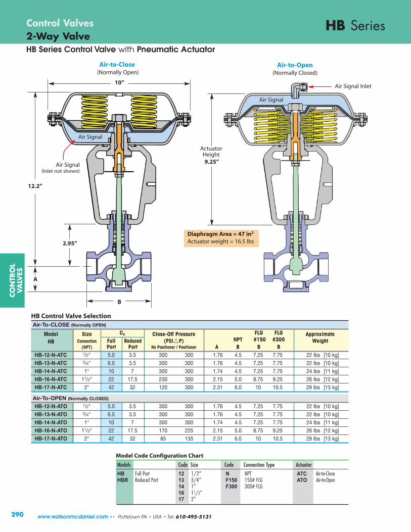
12.2”
B
10”
HB SeriesControl Valves2-Way Valve
Model Code Configuration Chart
Models Code Size Code Connection Type Actuator
HB Full Port 12 1/2” N NPT ATC Air-to-CloseHBR Reduced Port 13 3/4” F150 150# FLG ATO Air-to-Open
14 1” F300 300# FLG 16 11/2”17 2”
290
Air-to-Open(Normally Closed)
Air-to-Close(Normally Open)
ActuatorHeight9.25”
A
2.95”
HB Control Valve SelectionAir-To-CLOSE (Normally OPEN)
Model Size Cv Close-Off Pressure FLG FLG ApproximateHB Connection Full Reduced (PSI�P) NPT #150 #300 Weight
(NPT) Port Port No Positioner / Positioner A B B BHB-12-N-ATC 1/2" 5.0 3.5 300 300 1.76 4.5 7.25 7.75 22 lbs [10 kg]HB-13-N-ATC 3/4" 6.5 3.5 300 300 1.76 4.5 7.25 7.75 22 lbs [10 kg]HB-14-N-ATC 1" 10 7 300 300 1.74 4.5 7.25 7.75 24 lbs [11 kg]
HB-16-N-ATC 11/2" 22 17.5 230 300 2.15 5.0 8.75 9.25 26 lbs [12 kg]HB-17-N-ATC 2" 42 32 120 300 2.31 6.0 10 10.5 29 lbs [13 kg]
Air-To-OPEN (Normally CLOSED)
HB-12-N-ATO 1/2" 5.0 3.5 300 300 1.76 4.5 7.25 7.75 22 lbs [10 kg]HB-13-N-ATO 3/4" 6.5 3.5 300 300 1.76 4.5 7.25 7.75 22 lbs [10 kg]HB-14-N-ATO 1" 10 7 300 300 1.74 4.5 7.25 7.75 24 lbs [11 kg]HB-16-N-ATO 11/2" 22 17.5 170 225 2.15 5.0 8.75 9.25 26 lbs [12 kg]
HB-17-N-ATO 2" 42 32 85 135 2.31 6.0 10 10.5 29 lbs [13 kg]
Diaphragm Area = 47 in2
Actuator weight = 16.5 lbs
CO
NTR
OL
VA
LVES
www.watsonmcdaniel.com •• Pottstown PA • USA • Tel: 610-495-5131
Air Signal Inlet
Air Signal
Air Signal
Air Signal (Inlet not shown)
HB Series Control Valve with Pneumatic Actuator

Type 2000 Valve Positioner(Pneumatic or Electro-Pneumatic)
HB Series2-Way ValveControl Valves
291
Type-2000 Pneumatic Electro-Pneumatic Input Signal 3-15 PSI 4-20 mASupply Pressure 145 PSI maximum 21.8 - 145 PSILinearity Error 0.7 % full span <1.0% of full spanHysteresis 0.4 % full span <0.6% of full spanRepeatability 0.3 % full span <0.5% of full spanPressure Gain 750 P-out/P-in 750 P-out/P-inFlow Capacity SCFM SCFM
@20 PSI 9.5 9.5@87 PSI 28.3 28.3@145 PSI 47.1 47.1
Air Consumption SCFM SCFM@20 PSI 0.18 0.2@87 PSI 0.53 0.6@145 PSI 0.88 1.0
Impedance 260 Ohms at 70˚ FLoop Load 5.2 Volts at 70˚ FPort Size 1/4” NPT; 1/2” NPT
Gauge Ports 1/8” NPTTemperature Range -40˚ F – 185˚ FMedia Oil-free Instrument Air Filtered to 40 micronEnclosure NEMA 4X
Valve Positioner Model Code Configuration
Model Postioner Type Indicator Code
CA2000L1C3 Pneumatic None (Standard Linear) NCA2010L1C3 Electro-Pneumatic Dome (Option) DCA2020L1C3 Explosion-Proof
Type 2000 Valve Positioner(Pneumatic or Electro-Pneumatic)Type 2000 Valve Positioners (Pneumatic and Electro-Pneumatic) are mechanicaldevices designed to provide enhanced control, stability, and shut-off capability inextreme flow applications. The positioner, which is mounted to the valve’s yoke assembly and linked to the valve stem, receives a signal from an external control source, compares the control signal to the actual position of the valve plug, and then sends a corrected signal to the valve’s actuator, thereby positioning the valve plug for optimum flow modulation.
Example Model : CA2000L1C3N
CO
NTR
OL
VA
LVES
Tel: 610-495-5131 • Pottstown PA • USA •• www.watsonmcdaniel.com
HB Series Control Valve with Pneumatic Actuator

HB SeriesControl Valves2-Way ValveHB Series Control Valve with Electric Actuator
CO
NTR
OL
VA
LVES
292 www.watsonmcdaniel.com •• Pottstown PA • USA • Tel: 610-495-5131
Power Supply 115VAC 24VAC 24VDC
Nominal Current (A) 0.66 3.15 2
Max Current (A) 0.86 4.1 2.6
Max Power Consumption (W) 57 53 48
Force 1,100 lbs
Stem Velocity 0.088 - 0.177 in/sec
Nominal 3/4" Travel Time 6 - 8 sec
Duty Cycle, IEC 60034-1,8 S2 30min S4 50% ED @ 77°F
Ambient Temperature -4 to 140°F
Shut-off Pressure 300 psig(1/2” to 2” HB)
Actuator Weight 17.6 lbs
WMEA Electric Actuator Specifications
Features and Benefits
• Fast Response: These actuators are respond extremely fast and will fully open or close the HB Control Valve in approximately 6 seconds making them ideal for instantaneous and semi-instantaneous water heaters. Typical signal response time is 2-3 seconds.
• Fail-Safe Mode: Super capacitors are used to drive the valve fully-closed or open in the event of power loss to the actuator. This replaces common back-ups such as springs with limited thrust or batteries with a limited life span.
• High Stem Thrust: Allows close-off of all HB valves sizes againstthe full rating of 300 psig.
• Integral Positioner: Accepts 4/0-20mA or 2/0-10 VDC controlsignals, eliminating the need for a separate I/P transducer.
• Field-Configurable: Using a PC, the actuator can be field-configuredfor minimum closing position, maximum opening position, fail-open,fail-close or stay-put failure mode in the event of power loss.
Options & Associated Control Loop Accessories
• USB Kit for parameter customization• PID Electronic Controllers (TR890 Series)• Thermocouples• RTD’s• Pressure Transmitters
The HB Series Control Valve with Electric Actuator is a robust,user-friendly alternative to the standard pneumatic actuator onthe HB Series Control Valve. With fast and precise movement, thisactuator is designed to handle a broad range of applicationsincluding instantaneous and semi-instantaneous water heaters.Ideal for installations where pneumatic lines are not present orare prohibitive.
HB Series Control Valve
(with Electric Actuator)
Model Code Configuration Chart
Models Code Size Code Connection Type Actuator Power
HB Full Port 12 1/2” N NPT EFC Fail-Closed 24V 24VAC/DCHBR Reduced Port 13 3/4” F150 150# FLG EFO Fail-Open 115V 115VAC
14 1” F300 300# FLG 16 11/2”17 2”
Additional Technical InformationMotor Protection Electric motor current monitoring with
safety cut-offSet Value Feedback 4/0-20mA or 2/0-10 VDC selectable,
split range operationValve Positioner Function Integrated positioner, deadband adjustable
from 0.5 to 5%, shutoff minAutomatic Start-up Recognizing the end position(s) and
auto-scaling set and feedback valuesInternal Fault Monitoring Torque, set value, temperature, power supply,
positioning deviation, etcDiagnostic Function Stores accumulated operation data (motor &
total run time, number of starts) and data sets of current values (set value, feedback value, torque, temp, and error messages
Communication Interface USB interface with Software - enables parameter adjustments
Cable Glands 2x M20x1.5 & 1x M16x1.5
22.43”
2.95”
B
A
6.97”
(For valve dimensions referto HB Selection Chart )

9.3 [236]
Air Inlet1/8” NPT
Units: inches [mm]Weight: 9.6 lbs
[4.32 kg]
9.8 [249]
W910TB3-Way ValveControl Valves
CO
NTR
OL
VA
LVES
Actuator Housing Die cast aluminum, epoxy powdercoated blue finish.
Setting Scale Integral to housing
Adjustment Screw BrassSpring Cadmium plated
Pressure Plate Aluminum
Diaphragm Nylon reinforced EPDM
Air Pressure to 30 PSIG maximumDiaphragm
Air Connection 1/8 “ NPT Female
Operating Ambient:-40°F (-40°C) to 180°F (82°C)Temperature Process Flow:-40°F (-40°C) to 410°F (210°C)
W910TB Actuator Specifications
Models W910TBService Water, Other LiquidsSizes 1/2”, 3/4”, 1”, 11/4”, 11/2”, 2”,
21/2”, 3”, 4”Connections Union Ends, 125# Flanged
250# Flanged (optional)Body Material 1/2” – 2” Bronze
21/2” – 4” Cast Iron Seat Material Stainless SteelMax Inlet Pressure 250 PSIG
DESIGN PRESSURE/TEMPERATURE RATING – PMA/TMAUnion Ends 250 PSIG @ 450˚F125# FLG 125 PSIG @ 450˚F
for MIXING & DIVERTING • Water & Other Liquids
293
Typical Applications
W910TB 3-way Pneumatically-Actuated control valve can be used for mixing or diverting and are actuated by a 3-15 PSIG instrument airsignal placed to the top of the actuator housing that will modulate theposition of the valve.
3-way valves are used for mixing two flows together, or for diverting aflow to or around a device (bypass). In order to produce a consistent flow quantity for stable operation, the pressure drop across both flowpaths (inlet to outlet) must be nearly equal. The sleeve type design is constructed with an O-ring around the sleeve. The O-ring is suitable for water or glycol type service, up to a maximum of 300˚F. A higher temperature O-ring for use with other fluids, such as oil or for temperatures up to 410˚F, is available. Consult factory.
Principle of Operation
A control valve is comprised of an actuator mounted to a valve.The valve modulates flow through movement of a valve plug inrelation to the port(s) located within the valve body. The valveplug is attached to a valve stem, which, in turn, is connected tothe actuator. The pneumatic actuator directs the movement of thestem as dictated by the external control device.
NOT FOR USE WITH STEAM
3-WAY VALVE • Bronze - NPT
Valve Body is shownto demonstrate action of valve.
lowerport
B
upperport
C
common port
A
Tel: 610-495-5131 • Pottstown PA • USA •• www.watsonmcdaniel.com

Air Signal@ 50%
BC
A
Air Signal@ 0%
BC
A
Air Signal@ 100%
BC
A
Closed
Closed
MIXINGFLOW DIAGRAM
DIVERTINGFLOW DIAGRAM
CAUTION: 3-Way Valves are not designed for use in steam applications.
To properly control the mixing of two flows, inlet pressures at ports B and C should be as equal as possible.
Valve Body SelectionMixing or Diverting
Valve Body Actuator & Size Maximum Close-Off Pressure Dimensions ApproximateNumber Valve Model # (NPT) Cv (PSI�P) E F G Shipping Wt.
A18 W910TB-A18 1/2" 2.8 250 4.8 [122] 1.8 [46] 1.8 [46] 13 lbs [5.9 kg]
A25 W910TB-A25 3/4" 5.6 250 5.6 [142] 2.3 [58] 2.3 [58] 15 lbs [6.8 kg]
A34 W910TB-A34 1" 8.4 250 6.0 [152] 2.3 [58] 2.3 [58] 16 lbs [7.2 kg]
A45 W910TB-A45 11/4" 15 250 7.2 [183] 2.8 [71] 2.6 [66] 19 lbs [8.6 kg]
A56 W910TB-A56 11/2" 21 250 7.7 [196] 3.5 [89] 2.6 [66] 21 lbs [9.5 kg]
A67 W910TB-A67 2" 33 250 8.6 [218] 4.1 [104] 3.1 [79] 26 lbs [11.8 kg]
All dimensions are inches [mm].
SpecificationsBody Material Trim Material Trim Style Connection Pressure & Temperature Rating
Bronze Bronze Modified Linear NPT with Malleable Iron Union Ends 250 PSIG @ 300°F (149°C)
G
F
E
for Mixing or Diverting
3-Way • 1/2” – 2”
CO
NTR
OL
VA
LVES
W910TBControl Valves3-Way Valve Bodies • BRONZEfor MIXING & DIVERTING • Water & Other Liquids
294
Air Signal@ 50%
BC
A
Air Signal@ 0%
BC
A
Air Signal@ 100%
BC
A
Closed
Closed
common port A
upperport
C
lowerport
B
ActuatorMounting Surface
1/2” - 2”NPT/Union
www.watsonmcdaniel.com •• Pottstown PA • USA • Tel: 610-495-5131
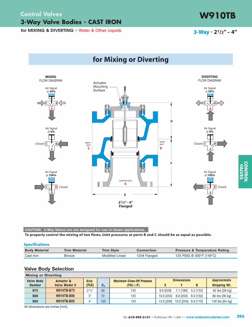
3-Way • 21/2” – 4”
SpecificationsBody Material Trim Material Trim Style Connection Pressure & Temperature Rating
Cast Iron Bronze Modified Linear 125# Flanged 125 PSIG @ 300°F (149°C)
G
F
E
LOWERPORT
(B)
COMMON PORT (A)
G
F
E
for Mixing or Diverting
MIXINGFLOW DIAGRAM
DIVERTINGFLOW DIAGRAM
CO
NTR
OL
VA
LVES
W910TB3-Way Valve Bodies - CAST IRONControl Valves
for MIXING & DIVERTING • Water & Other Liquids
295
lowerport
B
upperport
C
Air Signal@ 50%
BC
A
Air Signal@ 0%
BC
A
Air Signal@ 100%
BC
A
Closed
Closed
Air Signal@ 50%
BC
A
Air Signal@ 0%
BC
A
Air Signal@ 100%
BC
A
Closed
Closed
CAUTION: 3-Way Valves are not designed for use in steam applications.
To properly control the mixing of two flows, inlet pressures at ports B and C should be as equal as possible.
common port
A
ActuatorMounting Surface
21/2” - 4”Flanged
Tel: 610-495-5131 • Pottstown PA • USA •• www.watsonmcdaniel.com
Valve Body SelectionMixing or Diverting
Valve Body Actuator & Size Maximum Close-Off Pressure Dimensions ApproximateNumber Valve Model # (FLG) Cv (PSI�P) E F G Shipping Wt.
B75 W910TB-B75 21/2" 58 125 9.0 [229] 7.1 [180] 5.2 [132] 62 lbs [28 kg]
B80 W910TB-B80 3" 72 125 10.0 [254] 8.0 [203] 6.0 [152] 80 lbs [36 kg]
B85 W910TB-B85 4" 102 125 13.0 [330] 10.0 [254] 6.9 [175] 140 lbs [64 kg]
All dimensions are inches [mm].

296
Note: The Steam Capacity Chart is based on ISA Standard 75.01.01-2007 (60534-2-1 Mod). It assumes pipe sizes equal to the size of the valve ports, with no attached fittings.
CO
NTR
OL
VA
LVES
2-Way Valve Body • HB SeriesCapacity Charts
InletPressure(PSIG)
OutletPressure(PSIG)
CAPACITIES – Steam (lbs/hr)
4 1 48 68 89 136 300 573 5 0 5 96 137 178 274 602 1149
-4 9 114 162 211 325 714 1363 -8 13 119 170 220 339 746 1424 9 1 53 76 99 153 336 641 10 5 5 110 156 203 313 689 1315 0 10 138 197 255 393 865 1651
-7 17 148 211 274 422 929 1773 10 5 122 174 226 348 765 1460 15 5 10 156 223 290 447 983 1876 0 15 172 246 320 492 1082 2066
-5 20 177 252 328 505 1110 2119 15 5 133 189 246 379 833 1591 20 10 10 173 247 321 494 1088 2076 5 15 194 277 361 555 1221 2330
-3 23 205 293 381 587 1291 2464 25 5 152 217 282 434 955 1822 30 15 15 232 331 431 663 1459 2785 5 25 260 371 482 742 1631 3115 0 30 262 375 487 750 1649 3149 40 10 250 357 464 714 1570 2997 50 30 20 324 463 601 925 2035 3886 15 35 370 529 687 1057 2326 4440 7 43 376 537 697 1073 2361 4507 70 10 307 438 570 877 1929 3682 80 50 30 472 675 877 1350 2970 5670 30 50 534 763 992 1525 3356 6407 17 63 544 777 1010 1554 3418 6526 85 15 406 580 754 1160 2552 4872 100 60 40 586 837 1089 1675 3684 7034 40 60 643 918 1193 1836 4039 7710 23 77 655 936 1217 1872 4119 7864 110 15 452 645 839 1290 2838 5418 125 85 40 668 954 1240 1908 4199 8015 50 75 782 1117 1452 2233 4913 9380 31 94 794 1135 1475 2270 4993 9532 130 20 560 800 1040 1600 3519 6718 150 100 50 800 1143 1485 2285 5027 9598 70 80 904 1291 1678 2582 5680 10844 40 110 933 1333 1733 2666 5865 11196 150 25 666 952 1237 1903 4187 7994 175 115 60 931 1329 1728 2659 5850 11167 75 100 1052 1503 1953 3005 6612 12622 48 127 1072 1531 1990 3062 6736 12859 175 25 713 1018 1324 2037 4481 8554 200 130 70 1061 1515 1970 3031 6668 12730 90 110 1183 1690 2196 3379 7434 14192 56 144 1210 1729 2247 3457 7606 14521 225 25 798 1140 1482 2281 5017 9578 250 170 80 1273 1819 2364 3637 8002 15276 120 130 1443 2062 2680 4124 9072 17319 73 177 1487 2125 2762 4249 9348 17846 270 30 951 1359 1766 2718 5979 11414 300 200 100 1535 2193 2850 4385 9648 18418 140 160 1723 2461 3199 4922 10828 20672 89 211 1765 2521 3277 5042 11093 21177
Cv Factors
Orifice Size (in)
1/2" 1/2" 3/4" 1" 11/2" 2" 3.5 5.0 6.5 10 22 42
0.88 0.88 0.88 0.88 1.25 1.75
ReducedPort
CAPACITIES – Water (GPM)
5 4 1 3.5 5.0 6.5 10 22 42 0 5 7.8 11 15 22 49 94 7 3 6.1 8.7 11 17 38 73 10 5 5 7.8 11 15 22 49 94 0 10 11 16 21 32 70 133 10 5 7.8 11 15 22 49 94 15 5 10 11 16 21 32 70 133 0 15 14 20 26 39 86 165 25 5 7.8 11 15 22 49 94 30 15 15 14 19 25 39 85 163 7 23 17 24 31 48 106 203 40 10 11 16 21 32 70 133 50 30 20 16 22 29 45 98 188 16 34 20 29 38 58 128 244 70 10 11 16 21 32 70 133 80 50 30 19 27 36 55 120 230 30 50 25 35 46 70 155 296 85 15 14 19 25 39 85 163 100 65 35 21 30 38 59 130 248 40 60 27 39 50 78 171 326 110 15 14 19 25 39 85 163 125 85 40 22 32 41 63 139 266 52 73 30 43 56 86 188 360 130 20 16 22 29 45 98 188 150 100 50 25 35 46 71 156 297 63 87 33 47 60 93 205 391 175 25 18 25 33 50 110 210 200 130 70 29 42 54 84 184 351 87 113 37 53 69 106 234 446 225 25 18 25 33 50 110 210 250 170 80 31 45 58 89 197 376 111 139 41 59 77 118 260 495 270 30 19 27 36 55 120 230 300 200 100 35 50 65 100 220 420 134 166 45 64 84 129 283 540
Cv Factors
Orifice Size (in)
1/2" 1/2" 3/4" 1" 11/2" 2" 3.5 5.0 6.5 10 22 42
0.88 0.88 0.88 0.88 1.25 1.75
ReducedPort
www.watsonmcdaniel.com •• Pottstown PA • USA • Tel: 610-495-5131
ΔPPSI
InletPressure(PSIG)
OutletPressure(PSIG)
ΔPPSI
Note: 1) Capacities based on 70°F water (SG = 1.00).2) Capacities based on 100% of Cv.

297
CO
NTR
OL
VA
LVES
CAPACITIES – Water (GPM) 3-WAY VALVESInlet pressures should be within 5% of each other. Specify if service is for other than water.
Size, Body Number & Coefficient (Cv) 1/2” 3/4” 1” 11/4” 11/2” 2” 21/2” 3” 4”
PressureDrop A18 A25 A34 A45 A56 A67 B75 B80 B85
(PSI�P) Cv = 2.8 Cv = 5.6 Cv = 8.4 Cv = 15 Cv = 21 Cv = 33 Cv = 58 Cv = 72 Cv = 102
1 2.8 5.6 8.4 15 21 33 58 72 1023 4.8 10 15 26 36 57 100 125 1775 6.3 13 19 34 47 74 130 161 22810 8.9 18 27 47 66 104 183 228 32315 11 22 33 58 81 128 225 279 39520 13 25 38 67 94 148 259 322 45625 14 28 42 75 105 165 290 360 51030 15 31 46 82 115 181 318 394 55940 18 35 53 95 133 209 367 455 64550 20 40 59 106 148 233 410 509 72160 22 43 65 116 163 256 449 558 79070 23 47 70 125 176 276 485 602 85380 25 50 75 134 188 295 519 644 91290 27 53 80 142 199 313 550 683 968100 28 56 84 150 210 330 580 720 1020125 31 63 94 168 235 369 648 805 1140150 34 69 103 184 257 404175 37 74 111 198 278 437200 40 79 119 212 297 467225 42 84 126 225 315 495250 44 89 133 237 332 522
Note: Oil service or high temperature service requires special O-ring.
Capacity Chartfor MIXING & DIVERTING • Water & Other Liquids
W910TB • 3-Way Valve Body
W910TB Mixing & Diverting (3-Way Valves)
Tel: 610-495-5131 • Pottstown PA • USA •• www.watsonmcdaniel.com
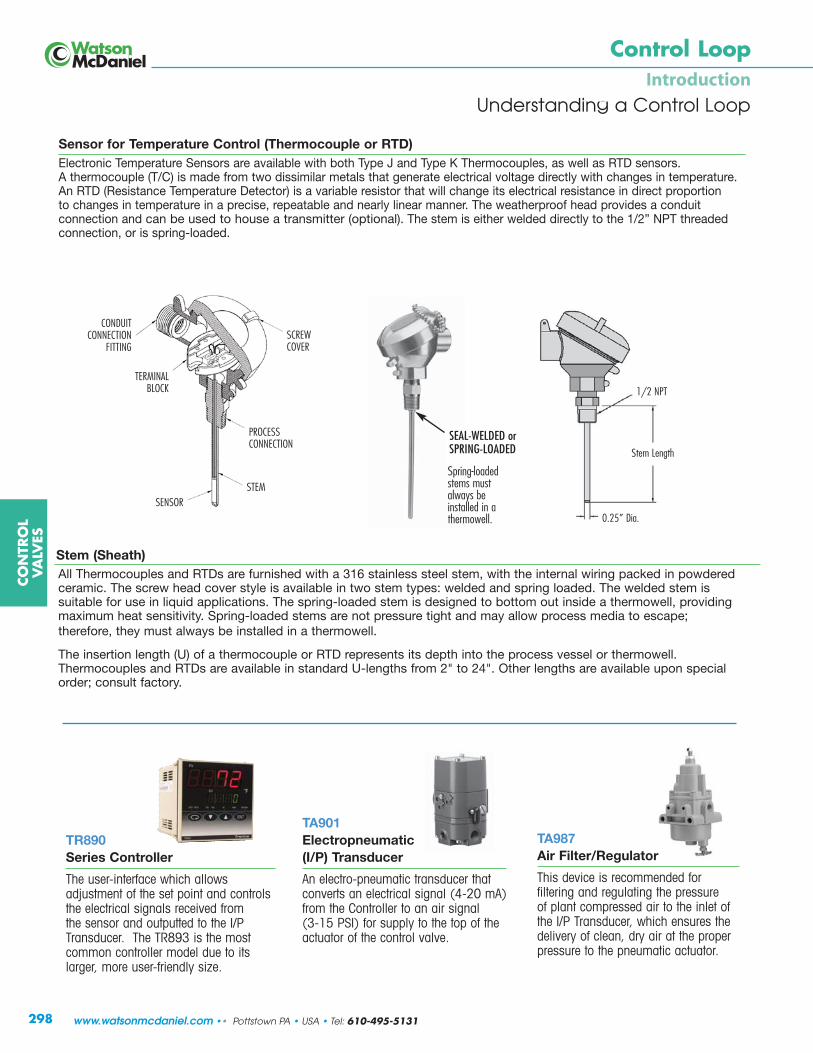
Stem (Sheath)All Thermocouples and RTDs are furnished with a 316 stainless steel stem, with the internal wiring packed in powderedceramic. The screw head cover style is available in two stem types: welded and spring loaded. The welded stem issuitable for use in liquid applications. The spring-loaded stem is designed to bottom out inside a thermowell, providingmaximum heat sensitivity. Spring-loaded stems are not pressure tight and may allow process media to escape; therefore, they must always be installed in a thermowell.
The insertion length (U) of a thermocouple or RTD represents its depth into the process vessel or thermowell.Thermocouples and RTDs are available in standard U-lengths from 2" to 24". Other lengths are available upon specialorder; consult factory.
298
CO
NTR
OL
VA
LVES
Control LoopIntroduction
Understanding a Control Loop
TR890Series Controller
The user-interface which allows adjustment of the set point and controlsthe electrical signals received from the sensor and outputted to the I/PTransducer. The TR893 is the mostcommon controller model due to itslarger, more user-friendly size.
TA901Electropneumatic (I/P) Transducer
An electro-pneumatic transducer thatconverts an electrical signal (4-20 mA)from the Controller to an air signal (3-15 PSI) for supply to the top of theactuator of the control valve.
TA987 Air Filter/Regulator
This device is recommended for filtering and regulating the pressure of plant compressed air to the inlet ofthe I/P Transducer, which ensures thedelivery of clean, dry air at the properpressure to the pneumatic actuator.
TERMINALBLOCK
SENSOR
CONDUIT CONNECTION
FITTING
STEM
PROCESSCONNECTION
SCREWCOVER
Stem Length
1/2 NPT
Sensor for Temperature Control (Thermocouple or RTD)Electronic Temperature Sensors are available with both Type J and Type K Thermocouples, as well as RTD sensors. A thermocouple (T/C) is made from two dissimilar metals that generate electrical voltage directly with changes in temperature.An RTD (Resistance Temperature Detector) is a variable resistor that will change its electrical resistance in direct proportion to changes in temperature in a precise, repeatable and nearly linear manner. The weatherproof head provides a conduit connection and can be used to house a transmitter (optional). The stem is either welded directly to the 1/2” NPT threadedconnection, or is spring-loaded.
SEAL-WELDED orSPRING-LOADED
Spring-loadedstems mustalways beinstalled in athermowell. 0.25” Dia.
www.watsonmcdaniel.com •• Pottstown PA • USA • Tel: 610-495-5131
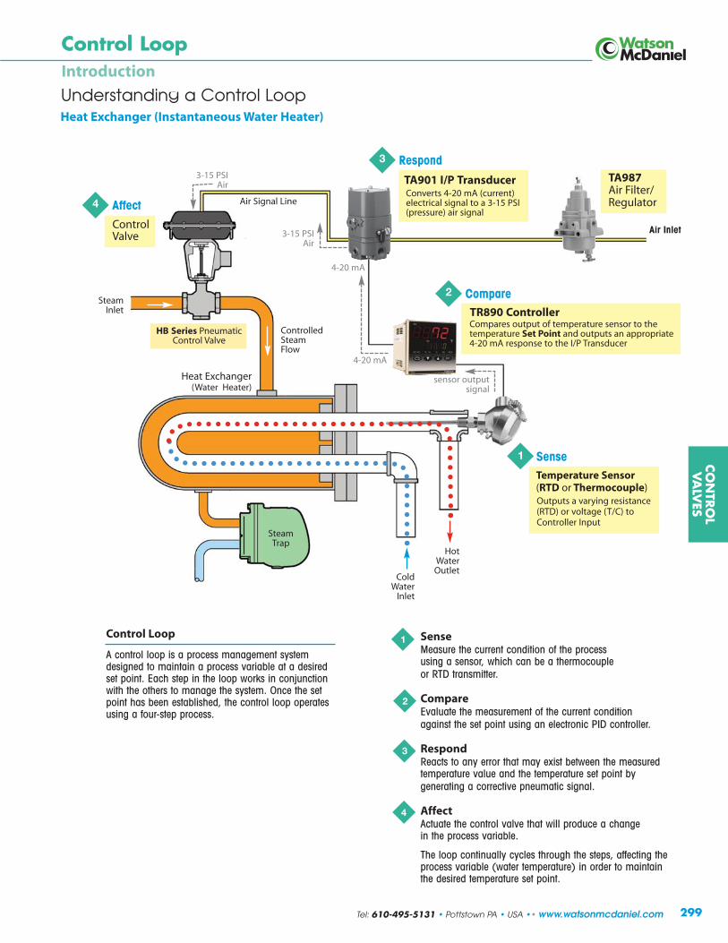
Understanding a Control Loop
Control Loop
A control loop is a process management systemdesigned to maintain a process variable at a desiredset point. Each step in the loop works in conjunctionwith the others to manage the system. Once the setpoint has been established, the control loop operatesusing a four-step process.
SenseMeasure the current condition of the process using a sensor, which can be a thermocoupleor RTD transmitter.
CompareEvaluate the measurement of the current condition against the set point using an electronic PID controller.
RespondReacts to any error that may exist between the measuredtemperature value and the temperature set point by generating a corrective pneumatic signal.
AffectActuate the control valve that will produce a change in the process variable.
The loop continually cycles through the steps, affecting theprocess variable (water temperature) in order to maintainthe desired temperature set point.
1
2
3
4
299
Air Signal Line
ColdWater
Inlet
Heat Exchanger(Water Heater)
SteamInlet
Heat Exchanger (Instantaneous Water Heater)
SteamTrap
Control LoopIntroduction
2 Compare
3 Respond
1 Sense
TA901 I/P TransducerConverts 4-20 mA (current) electrical signal to a 3-15 PSI (pressure) air signal
Compares output of temperature sensor to the temperature Set Point and outputs an appropriate 4-20 mA response to the I/P Transducer
TR890 Controller
Temperature Sensor(RTD or Thermocouple)Outputs a varying resistance(RTD) or voltage (T/C) toController Input
Hot WaterOutlet
CO
NTR
OL
VA
LVES
4 AffectControl Valve
TA987Air Filter/Regulator
Air Inlet
HB Series PneumaticControl Valve
ControlledSteamFlow
sensor output signal
4-20 mA
4-20 mA
3-15 PSIAir
3-15 PSIAir
Tel: 610-495-5131 • Pottstown PA • USA •• www.watsonmcdaniel.com

Description
A controller is a comparative device that receives an input signal from a measured processvariable, compares this value with that of a predetermined control point value (set point),and determines the appropriate amount of output signal required by the final control element to provide corrective action within a control loop.
Principle of Operation (Electronic PID Controller)
An electronic sensor (thermocouple, RTD or transmitter) installed at the measurement location continuously sendsan input signal to the controller. At set intervals, the controller compares this signal to a predefined set point. If the input signal deviates from the set point, the controller sends a corrective electric output signal to the controlelement. This electric signal must be converted to a pneumatic signal when used with an air operated valve, suchas a Watson McDaniel HB Series Control Valve. The conversion can be made using a Watson McDaniel TA901 I/P Transducer, which converts a 4 to 20 mA electric signal to a 3 to 15 PSI air signal. As an option, a ValvePositioner such as the Watson McDaniel CA2000 may be used to send an air signal to the Control Valve. ThesePositioners can be controlled with a 3-15 psi air signal from a Pneumatic Controller or a 4-20 mA signal from a PID Controller.
Features (Electronic PID Controller)
Watson McDaniel Electronic Controllers have full auto-tuning and PID capabilities, and offer a host of available options, including user selectable inputs, outputs and ranges.
PID Control is a feature of Watson McDaniel TR890 Electronic Controllers. PID combines the proportional, integral and derivative functions into a single unit.
• Proportional (P) — Proportional control reacts to the size of the deviation from set point when sending a corrective signal. The size of the corrective signal can be adjusted in relation to the size of the error by changing the width of the proportional band. A narrow proportional band will cause alarge corrective action in relation to a given amount of error, while a wider proportional band will a cause smaller corrective action in relation to the same amount of error.
• Integral (I) — Integral control reacts to the length of time that the deviation from set point exists when sending a corrective signal. The longer the error exists, the greater the corrective signal.
• Derivative (D) — Derivative control reacts to the speed in which the deviation is changing. The corrective signal will be proportional to the rate of change within the process.
Auto-Tuning will automatically select the optimum values for P, I and D, thus eliminating the need for the user tocalculate and program these values at system startup. This feature can be overridden when so desired. On somemodels, the control element can be manually operated.
CO
NTR
OL
VA
LVES
ControllersIntroduction
300
Design and Operation of an Electronic PID Controller
www.watsonmcdaniel.com •• Pottstown PA • USA • Tel: 610-495-5131

Selecting an Electronic PID Controller
When selecting a PID controller, the following parameters must be specified. (Refer to the TR890 SeriesElectronic PID Controller Specifications and Model Coding chart on the following two pages.)
1) Model (Case Size)
The Case Size selection is determined by both available and designed space, and controller features.Watson McDaniel Electronic Controllers are available in the following panel sizes:
TR891: 48 x 48 mm (1/16 DIN) TR893: 96 x 96 mm (1/4 DIN)TR892: 72 x 72 mm TR894: 96 (H) x 48 (W) mm (1/8 DIN)
2) Input
The Input is the measurement signal received by the controller from the sensor. One of the following three input typescan be specified for the controller: 8: Universal, 4: Current or 6: Voltage. The Universal input type is switchablebetween Thermocouple, RTD and mV input signals. If temperature will be measured with a thermocouple or RTD sensor, the Universal input type must be selected for thecontroller (Model Code Position 2 = 8). If another process variable such as PRESSURE is being measured, verify thetype of output signal from that sensor. If it’s 4-20 mA or 0-10 Volts then the Current or Voltage input option would bechosen, respectively.
3) Control Output
The Control Output is the corrective signal transmitted from the controller to the control device. One of the following four control output types can be specified for the controller: I: 4-20 mA DC, Y: On/Off Contact, P: Solid State Relay (SSR) Driver or V: 0-10 VDC. The most common control devices are the TA901 Electro-pneumatic (I/P) Transducer and CA2000-Series ValvePositioner with built-in I/P transducer, both of which accept a 4-20 mA signal. For these devices, the 4-20 mA control output type must be selected for the controller (Model Code Position 3 = I). The TA901 or CA2000-Series output an air signal to the actuator of the Control Valve, which is the final control element of the feedback loop. The On/Off Contact and SSR Driver control output types are typically used to switch on AC power to a load. If the SSR Driver control output is selected, an external solid state relay (SSR) is required and can be used for activating electrical equipment with larger current requirements.
4) Power Supply
The power supply requirement for the electronic controller must be specified. The available choices are: 100-240 VAC, 50/60 Hz or 24 V AC/DC, 50/60Hz.
5) Event Output (Option)
The Event Output is used to signal an external device when an alarm condition is detected. Various alarm types canbe detected by the controller. These include deviation of the measured value from the set value, the measured valueexceeding absolute limits (i.e., high and low level alarm) and heater break/loop alarm (i.e., heater current outside ofnormal limits). If selected as an option, the controller will have two Event Outputs. In the case of a high/low alarm,one output is used for the high level alarm and the other for the low level alarm.
6) Options: Analog Output & Digital Input
The Analog Output is an optional secondary signal that transmits either the measured process value (PV), the targetset value (SV) or the Control Output value from the controller to a remote data acquisition device, such as a recorder,personal computer or display unit. One of the following three analog output types can be specified for the controller:0-10 mV DC, 4-20 mA DC or 0-10 V DC. The analog output type is independent of the measured input type or thecontrol output type. However, the analog output type selection must be compatible with the data acquisition deviceinput.
The Digital Input is an optional input that can be specified for the controller. The digital input functions as an On/Offswitch and can be programmed to activate the Set Value Bias or Standby mode, or switch the Control Action type(i.e., to Reverse Acting or Direct Acting).
Note: The Analog Output and Digital Input combination is not available for Model TR891. Only one of these options can be selected for this model.
CO
NTR
OL
VA
LVES
ControllersIntroduction
301
Design and Operation of an Electronic PID Controller
Tel: 610-495-5131 • Pottstown PA • USA •• www.watsonmcdaniel.com

Features PID & Auto-tuning
Use of a Watson McDaniel No. TA987 Air Filter/Regulator is recommended for filtering and regulating the pressure ofplant compressed air, and fordelivering clean, dry air at the proper pressure to pneumatic control devices.
S p e c i f i c a t i o n s
Multiple Sizes
+ 0.3% Accuracy
Keyboard Programmable
Reverse or Direct Acting
Manual Output Override
Models TR891: 48 x 48 mm (1/16 DIN)TR892: 72 x 72 mmTR893: 96 x 96 mm (1/4 DIN)TR894: 96 x 48 mm (1/8 DIN)
Control Control Mode: Auto-Tuning PIDAction: Reverse acting (field switchable to direct acting)
Proportional Off, 0.1-999.9% Full ScaleBand Integral Time: Off, 1-6000 sec.
Derivative Time: Off, 1-3600 sec.
Accuracy + 0.3%
Display Process Value: 4 Digit, 20 mm red LEDSet Value: 4 digit, 10.2 mm green LEDSampling Cycle: 0.25 seconds
Inputs Universal: (switchable between)Thermocouple: B, R, S, K, E, J, T, N, PL II, WRe5-26 (U,L (DIN 43710)RTD: Platinum 100 Ω, 3-Wire mV: (scalable) -10–10, 0-10, 0-20, 0-50, 10-50, 0-100 mV DC
Current: (scalable) 4-20, 0-20 mAVoltage: -1–1, 0-1, 0-2, 0-5, 1-5, 0-10 VDC
Current: 4-20 mA (load resistance: 600 Ω maximum)Contact: Proportional cycle, 1-120 sec. (capacity: 240 VAC 2 A resistive / 1.2 A inductive)
SSR Drive Voltage: Proportional cycle 1-120 sec.(output rating: 12 ± 1.5 VDC / 30 mA maximum)
Voltage: 0-10 VDCLoad Current 2 mA max
Power Supply Voltage: 100-240 VAC, 50/60 Hz or 24 VAC/VDC 50/60 Hz Requirements
Data Storage Nonvolatile EEPROM memory
Case Material Polyphenylene Oxide (PPO)
Ambient Temp. 14°F (-10°C) to 122°F (50°C)
Humidity Maximum: 90% RH, non-condensing
The TR890 Series ElectronicPID Controller is designed foruse on applications wherelarge load changes are expected, or extreme accuracyand fast response times areneeded. With full auto-tunecapabilities and a large selection of available inputs,the TR890 Series is ideally suited for use with a WatsonMcDaniel Control Valve.
Event Outputs(Contact Capacity: 240 VAC, 1 A/resistive load)
Dual Event Outputs (High and/or Low Alarms)Single Event Output + Heater Break Alarm (includes CT30A sensor)Single Event Output + Heater Break Alarm (includes CT50A sensor)
Options:Analog Output: 0-10 mV DC (output resistance 10 Ω )Analog Output: 4-20 mA DC (load resistance 300 Ω max )Analog Output: 0-10 VDC (load current 2 mA max )
Digital Input (switch) including:Set Value Bias setting range of -1999 - 5000, standby or DA/RA SelectionOperated by either non-voltage contact or open collector input rated at approx. 5V DC/1mA max.
Consumption: 100-240 VAC, 15VA 24 VDC, 8W24 VAC, 9VA
Approximate Shipping Weights:TR891: 0.4 lbs [0.17 kg]TR892: 0.6 lbs [0.28 kg]TR893: 0.7 lbs [0.33 kg]TR894: 0.5 lbs [0.24 kg]
Control Output
CO
NTR
OL
VA
LVES
TR890 SeriesControl ValvesElectronic PID Controllers
302 www.watsonmcdaniel.com •• Pottstown PA • USA • Tel: 610-495-5131

Model Input Control Output Power Supply Event Output Options
TR891 8 Universal I 4-20 mA 90 100-240 VAC, 50/60 Hz 0 None 00 NoneTR892 4 mA Y On/Off Contact 08 24 VAC/VDC, 50/60 Hz 1 Dual Event 30 Analog Output (0-10 mVDC)TR893 6 VDC P SSR Driver (high and/or low) 40 Analog Output (4-20 mA)TR894 V 0-10 VDC 2 Single Event 60 Analog Output (0-10 VDC)
(high or low) and 08 Digital Input (switch)heater break CT30A 38 Digital Input (switch) with
3 Single Event 0-10 mVDC* Analog Output(high or low) and 48 Digital Input (switch) heater break CT50A with 4-20 mA* Analog Output
68 Digital Input (switch) with 0-10 VDC* Analog Output
HOW TO ORDER (Model Coding) Sample Order Number: TR893 8 I 90 1 00
Event Outputs2 or 3 requireControl OutputsY or P
*Not available with Model TR891
W
H
DC
A
B
PANEL CUTOUT DIMENSIONS
Model A B C D H WTR891 1.77 [45] 1.77 [45] 0.43 [11] 3.94 [100] 1.89 [48] 1.89 [48]TR892 2.68 [68] 2.68 [68] 0.43 [11] 3.94 [100] 2.83 [72] 2.83 [72]TR893 3.63 [92] 3.63 [92] 0.43 [11] 3.94 [100] 3.78 [96] 3.78 [96]TR894 1.77 [45] 3.63 [92] 0.43 [11] 3.94 [100] 3.78 [96] 1.89 [48]
Programmable RangesThermocouple Inputs RTD Inputs Current & Voltage InputsT/C Range Fahrenheit Range Celsius Range Fahrenheit Range Celsius Range RangeType Code Range Code Range Code Range Code Range Code (User-scalable Readout)
B* 15 0° to 3300°F 01 0° to 1800°C 47 -300° to 1100°F 31 -200° to 600°C 71 -10–10 mV
E 21 0° to 1300°F 07 0° to 700°C 48 -150.0° to 200.0°F 32 -100.0° to 100.0°C 72 0-10 mV
J 22 0° to 1100°F 08 0° to 600°C 49 -150° to 600°F 33 -100.0° to 300.0°C 73 0-20 mV
K 18 -150° to 750°F 04 -100.0° to 400.0°C 50 -50.0° to 120.0°F 34 -50.0° to 50.0°C 74 0-50 mV
K 19 0° to 1500°F 05 0° to 800°C 51 0.0° to 120.0°F 35 0.0° to 50.0°C 75 10-50 mV
K 20 0° to 2200°F 06 0° to 1200°C 52 0.0° to 200.0°F 36 0.0° to 100.0°C 76 0-100 mV
L 28 0° to 1100°F 14 0° to 600°C 53 0.0° to 400.0°F 37 0.0° to 200.0°C 81 -1–1 V
N 24 0° to 2300°F 10 0° to 1300°C 54 0° to 1000°F 38 0.0° to 500.0°C 82 0-1 V
PL II 25 0° to 2300°F 11 0° to 1300°C 83 0-2 V
R 16 0° to 3100°F 02 0° to 1700°C 84 0-5 V
S 17 0° to 3100°F 03 0° to 1700°C 85 1-5 V
T 23 -300° to 400°F 09 -199.9° to 200.0°C 86 0-10 V
U 24 -300° to 400°F 13 -199.9° to 200°C 94 0-20 mA
WRe5-26 26 0° to 4200°F 12 0° to 2300°C 95 4-20 mA
Range Codes are not required for ordering, but are used for field programming.*750°F (400°C) falls below the accuracy range
Electronic PID Controller Dimensions – units: inches [mm]
CO
NTR
OL
VA
LVES
TR890 SeriesElectronic PID ControllersControl Valves
Features PID & Auto-tuning
303
1 2 3 4 5 6
Tel: 610-495-5131 • Pottstown PA • USA •• www.watsonmcdaniel.com

Electropneumatic
TA901Control ValvesI/P Transducer
Specifications
The TA901 I/P Transducer is tested and approved by Factory Mutual asIntrinsically Safe Class I, II and III, Division I, Groups C, D, E, F and G wheninstalled in accordance with the Installation, Operation and MaintenanceInstructions. It should be installed in a vertical position in a vibration-free area.
The Watson McDaniel TA987 Air Filter/Regulator is recommended for filteringand regulating the pressure of plant compressed air, and for delivering clean, dry air at the proper pressure to pneumatic control devices.
The TA901 Electropneumatic (I/P) Transducer converts a milliampcurrent signal to a linearly proportional pneumatic output pressure. Thistransducer is designed for control applications that require a high degreeof reliability and repeatability. The TA901 is used in the control operationof valve actuators and pneumatic valve positioners in the petrochemical,HVAC, energy management, textile, paper, and food & drug industries.
ModelTA901
Input4-20 mA
Output1-17 PSIG Per ANSI/FCI 87-2(can be calibrated to provide 1-9 PSIG or 9-17 PSIG)
Volume Booster Built-in volume booster allows flow capacity up to 20 SCFM
ConnectionsPneumatic: 1/4” NPT
Electric: 1/2” NPT
Air RequirementsClean, oil-free, dry air filtered to 40 microns
Minimum Supply Pressure: 3 PSIG
Maximum Supply Pressure:100 PSIG
Sensitivity: < ±0.1% of spanper PSIG
Air Consumption: 0.03 SCFHtypical
Flow Rate: 4.5 SCFM at25 PSIG supply
Relief Capacity: 2.0 SCFM at5 PSIG above 20 PSIG setpoint
MountingPipe, panel or bracket in avibration-free area. Field adjustment will be required ifmounted in a nonvertical position.
AdjustmentAdjustable zero and span
AccuracyTerminal Based Linearity:< ±0.75% of span
Repeatability: < 0.5% of span
Hysteresis: < 1.0% of span
Response Time: < 0.25 sec. @3-15 PSIG
Intrinsic SafetyTested and approved byFactory Mutual as IntrinsicallySafe Class I, II and III, DivisionI, Groups C, D, E, F and Gwhen installed in accordancewith Installation, Operation andMaintenance Instructions
Ambient Temperature-20°F (-30°C) to 140°F (60°C)
Approximate ShippingWeight2.1 lbs [0.94 kg]
10-32 UNF-2A X .38 DEEPMOUNTING HOLES
18 GA. WIRE LEADS18" LONG
BLACK-POSITIVE / WHITE-NEGATIVE
MOUNTING BRACKET
1/4 NPT
1.10[27.9]
1.09[27.7]
2.18 [55.4]MAX. SQUARE
4.24[107.7]
1/2NPT
1.50[38.1]
1.50[38.1]
Ø1.13[28.7]
.55 [14.0]
.55[14.0]
.55 [14.0]
2.88[73.1]
Ø.21 [5.4]
1.25 [31.8]
1.43[36.2]
Unit: inches [mm].
How to Order
Order using Item Number: TA901
4 to 20 mAInput
3 to 15 PSI Output
Intrinsically Safe
Zero and SpanAdjustments
CO
NTR
OL
VA
LVES
304 www.watsonmcdaniel.com •• Pottstown PA • USA • Tel: 610-495-5131

The maximum allowable supply pressure to TA987 Air Filter/Regulatoris 250 PSIG. Improper application may cause failure of the regulator,resulting in possible personal injury or property damage.
TA987Air Filter/RegulatorControl Valves
Specifications
Model TA987
Air RequirementsMaximum Supply Pressure:250 PSIG
Output Range:0 to 30 PSIG, adjustable
Sensitivity: 0.036 PSIG
Air Consumption: < 6 SCFH
Air Requirements (con’t.)Flow Rate: 20 SCFM at 100PSIG supply/20 PSIG output
Relief Capacity: 0.1 SCFM at5 PSIG above setpoint
Effect of Supply PressureVariation: < 0.2 PSIG for 25 PSIG
FilterRemoves particles 40 micronsor greater
Port Size1/4” NPT
HousingCast aluminum
MountingSide, pipe, panel or through body
Ambient Temperature-20°F (-30°C) to 160°F (71°C)
Approximate ShippingWeight1.9 lbs [0.86 kg]
Cast Aluminum Housing
Removable Nylon Mesh Filter
Low Air Consumption
Drip Well
GAUGEPORT
.05 [1.2]TO CLOF
GAUGEPORT
VENT
1.44[36.6]
2.06[52.3]
2.14[54.4]
.75[19.1]
OUT
1.25[31.8]
2.25[57.2]
Ø.36 [9.1]THRU 2 HOLES
1/4-20 UNC.44 [11.1] DEEP
2 HOLES
7.25[184.2]
10-24 UNC2 HOLES
2.10[53.3]
2.75[69.9]
3.19[81.0]
Ø.44[11.2]
.31 [7.9] SQUARE
Units: inches [mm].
The TA987 Air Filter/Regulator is recommended for filtering and regulating the pressure of plant compressed air, and for deliveringclean, dry air at the proper pressure to pneumatic control devices. Supply airenters the inlet port, passes through the filtering element, and exits throughthe reducing valve to the outlet port. The filtering element removes particlesas small as 40 microns. A drip well is provided for the accumulation of oil and water and a drain cock is included to allow purging of the unit. The filtering element is readily accessible for cleaning by removal ofthe drip well bowl.
3.19[81.0]
CO
NTR
OL
VA
LVES
305
How to Order
Order using Item Number: TA987
Tel: 610-495-5131 • Pottstown PA • USA •• www.watsonmcdaniel.com
1/2 NPT
STEMLENGTH
3.40[86.2]
3.91[99.4]
Ø3.30[83.8]
Ø.25[6.4]
Thermocoupleor RTD
Cast AluminumPolypropyleneor Stainless Steel Head
Weather-Proof
Welded orSpring LoadedStem
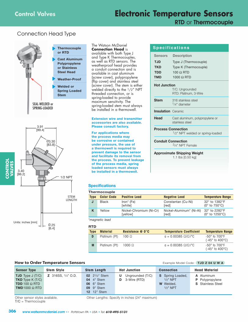
The Watson McDanielConnection Head is available with both Type J and Type K Thermocouples, as well as RTD sensors. Theweatherproof head provides a conduit connection and is available in cast aluminum (screw cover), polypropylene (flip cover) and stainless steel(screw cover). The stem is eitherwelded directly to the 1/2” NPTthreaded connection, or is spring-loaded to provide maximum sensitivity. The spring-loaded stem must alwaysbe installed in a thermowell.
S p e c i f i c a t i o n s
Sensors Description
TJD Type J (Thermocouple)
TKD Type K (Thermocouple)
TDD 100 Ω RTDTMD 1000 Ω RTD
Hot JunctionT/C: UngroundedRTD: Platinum, 3-Wire
Stem 316 stainless steel1/4" diameter
Insulation Ceramic
Head Cast aluminum, polypropylene orstainless steel
Process Connection1/2” NPT welded or spring-loaded
Conduit Connection3/4” NPT Female
Approximate Shipping Weight1.1 lbs [0.50 kg]
Extension wire and transmitteraccessories are also available.Please consult factory.
For applications wherethe process media maybe corrosive or containedunder pressure, the use ofa thermowell is required toprevent damage to the sensorand facilitate its removal fromthe process. To prevent leakageof the process media, springloaded sensors must alwaysbe installed in a thermowell.
How to Order Temperature Sensors Example Model Code: TJD Z 04 U W A
Sensor Type Stem Style Stem Length Hot Junction Connection Head Material
TJD Type J (T/C) Z 316SS, 1/4” O.D. 02 21/2" Stem U Ungrounded (T/C) S Spring Loaded, A AluminumTKD Type K (T/C) 04 4" Stem D 3-Wire (RTD) 1/2” NPT P PolypropyleneTDD 100 Ω RTD 06 6" Stem W Welded, S Stainless SteelTMD1000 Ω RTD 09 9" Stem 1/2” NPT
12 12" Stem
Other sensor styles available. Other Lengths: Specify in inches (24" maximum)T/C = Thermocouple
ThermocoupleType Color Code Positive Lead Negative Lead Temperature Range
J Black Iron* (Fe) Constantan (Cu-Ni) 32° to 1382°F [white] [red] (0° to 750°C)
K Yellow Nickel-Chromium (Ni-Cr) Nickel-Aluminum* (Ni-Al) 32° to 2282°F [yellow] [red] (0° to 1250°C)
*magnetic lead
RTDType Material Resistance @ 0°C Temperature Coefficient Temperature Range
D Platinum (Pt) 100 Ω a = 0.00385 Ω/Ω /°C -50° to 700°F (-45° to 400°C)
M Platinum (Pt) 1000 Ω a = 0.00385 Ω/Ω /°C -50° to 700°F (-45° to 400°C)
Units: inches [mm]
Specifications
CO
NTR
OL
VA
LVES
Electronic Temperature SensorsControl Valves
Connection Head Type
306
RTD or Thermocouple
www.watsonmcdaniel.com •• Pottstown PA • USA • Tel: 610-495-5131
SEAL-WELDED orSPRING-LOADED

Standard (9” - 24”)
Pressure Ratings (PSI)Operating Temperature
Material 70°F 200°F 400°F 600°F 800°F 1000°FCarbon steel 5000 5000 4800 4600 3500 -304 stainless steel 6550 6000 4860 4140 3510 3130
316 stainless steel 6540 6400 6000 5270 5180 4660
Standard Lagging(A) U (T) U
Stem Length Length Lagging Extension Length
21/2" 1.75 [44] — —
4” 2.50 [64] 1.00 [25] 1.50 [38]
6” 4.50 [114] 2.00 [51] 2.50 [64]
9” 7.50 [191] 3.00 [76] 4.50 [114]
12” 10.50 [267] 3.00 [76] 7.50 [191]
15” 13.50 [343] 3.00 [76] 10.50 [267]
18” 16.50 [419] 3.00 [76] 13.50 [343]
24” 22.50 [572] 3.00 [76] 19.50 [495]
How to Order 76-Series Thermowells Example Model Code: 76-4JN6
Thermowell Model (P) External Thread (A) Stem Length (T) Lagging Extension Material
76 Thermowell 3 1/2 NPT* D 21/2" Stem A 1" Extension (4" Stem only) 2 Brass4 3/4 NPT G 4" Stem C 2" Extension (6" Stem only) 5 304SS5 1 NPT* J 6" Stem E 3" Extension (9" thru 24” Stem only) 6 316SS
M 9" Stem N No ExtensionR 12" StemV 15" StemWa 18" StemWk 24" Stem
*Not available with 21/2" Stem Length
Standard (2 1/2" - 6") (A)
STEM LENGTH(A)STEM LENGTH
(P)EXTERNALTHREAD
ULENGTH
ULENGTH
1/2 NPSM
1/2 NPSM
1.00[25]
.75 [19]
.40 [10]
.61 [15]
Ø.260 [7]Ø.260 [7]
Ø.50 [13]
Ø.44 [11]
Lengths
Units inches: [mm]
Other thermowell styles available. Please consult factory.
(A)STEM LENGTH
(T)LAGGING
EXTENSION
(P)EXTERNAL THREAD
ULENGTH
1/2 NPSM
1.00[25]
.75 [19]
Ø.260 [7]
Ø.50 [13]
(P)EXTERNALTHREAD
with Lagging Extension (4” - 24”)
CO
NTR
OL
VA
LVES
Thermowellsfor RTD & Thermocouple Temperature Sensors
Control Valves
307
A Thermowell is a pressure tight receptacle designed to accept a temperature sensing element and provide a means to insert that element into a vessel or pipe. It acts as a barrier between a process medium and the sensing element ofa temperature measuring device and protects against corrosive process media. A thermowell also allows the sensing element to be removed from the application while maintaining a closed system. The material chosen must be compatiblewith the process medium to which it is exposed.
The U-length (insertion length) of a thermowell indicates its insertion depth into a process vessel or piping system and ismeasured from the tip of the thermowell to the underside of the threads. Lagging extension thermowells are used onapplications where insulation covers the vessel or piping system. The extension length (T-length) is the measurementbetween the instrument connection and process connection of the thermowell.
Tel: 610-495-5131 • Pottstown PA • USA •• www.watsonmcdaniel.com