watt-hour meter reference design - microchip...
TRANSCRIPT

Whm.bk Page 1 Wednesday, July 29, 1998 2:18 PM
M PICREF-3Watt-Hour Meter Reference Design
INTRODUCTION
The PICREF-3 Watt-Hour Meter (WHM) ReferenceDesign shows the use of a mixed signal microcontrollerin an AC power measurement application.
The traditional sensor signal processing chain consist-ing of sensor, signal conditioning electronics, A/D con-verter and microcontroller is abbreviated by the use ofthe mixed signal microcontroller with its on-board A/Dconverter.
The mixed signal microcontroller used is the MicrochipPIC16C924. This microcontroller has five A/D chan-nels, two of which are used to digitize voltage and cur-rent signals. The microcontroller features of pulse widthmodulation (PWM) and direct liquid crystal display(LCD) drive are utilized to further reduce cost and partscount.
The PWM output feature is used with a single pole RCfilter to provide a comparator reference with 10 bits ofresolution.
The direct LCD drive is used to drive an 8-digit,7-segment LCD.
MICROCONTOLLER BENEFITS
The use of a PIC16C924 microcontroller in a powermeter offers the following advantages:
• Real-Time Electrical Measurement and Power/Energy Calculations
• Direct LCD Drive- Present Time- Total Watt-Hours (Whr)- Maximum or Cumulative Demand
• Customization• Quick Time-to-Market
PICREF-3 OVERVIEW
The WHM Reference Design provides a cost effectivecircuit capable of monitoring and displaying power andenergy consumption on worldwide power mains in the90V to 264V range.
The PIC16C924 microcontroller shows that thereal-time events of sampling voltage and current wave-forms can be interleaved with power and energy calcu-lations. All measurements and calculations areperformed once per second.
The current waveforms measured are linear for resis-tive and inductive loads and non-linear for switchingpower supplies. The current waveform is sampled dur-ing the positive current cycle with waveform symmetryassumed between positive and negative cycles (validfor the measured waveforms). A hardware method forfull cycle current measurements and firmware methodsfor complex current waveform shapes are provided inthe Design Modifications section.
PICREF-3 KEY FEATURES
• Accepts polarized and unpolarized worldwide power mains.
• Measures and displays AC Voltage (90V to 264V), Load Current and Power Factor.
• Measures power line frequency (47 Hz to 63 Hz).• Calculates Watts, Watt-Hrs and cumulative
Watt-Hrs and displays these values, as well as frequency and time.
• True RMS measurements.• Firmware control of triac load switch on/off state.• Real time clock during power-saving sleep mode.• Hibernate mode to save on battery life during stor-
age.• Battery back-up for microcontroller.
ã 1997 Microchip Technology Inc. Preliminary DS30452A-page 1
INFORMATION CONTAINED IN THIS PUBLICATION IS INTENDED THROUGH SUGGESTION ONLY AND MAY BE SUPERSEDED BY UPDATES.NO REPRESENTATION OR WARRANTY IS GIVEN AND NO LIABILITY IS ASSUMED BY MICROCHIP TECHNOLOGY INC. WITH RESPECT TOTHE ACCURACY OR USE OF SUCH INFORMATION, OR INFRINGEMENT OF PATENTS ARISING FROM SUCH USE OR OTHERWISE. IT ISTHE RESPONSIBILITY OF EACH USER TO ENSURE THAT EACH WATT-HOUR METER IS ADEQUATELY DESIGNED, SAFE, AND COMPATI-BLE WITH ALL CONDITIONS ENCOUNTERED DURING ITS USE. "TYPICAL" PARAMETERS CAN AND DO VARY IN DIFFERENT APPLICA-TIONS. ALL OPERATING PARAMETERS, INCLUDING "TYPICALS", MUST BE VALIDATED FOR EACH CUSTOMER APPLICATION BY THECUSTOMER'S TECHNICAL EXPERTS. USE OF MICROCHIP'S PRODUCTS AS CRITICAL COMPONENTS IN LIFE SUPPORT SYSTEMS IS NOTAUTHORIZED EXCEPT WITH EXPRESS WRITTEN APPROVAL BY MICROCHIP. NO LICENSES ARE CONVEYED, IMPLICITLY OR OTHERWISE,UNDER ANY INTELLECTUAL PROPERTY RIGHTS.

PICREF-3
Whm.bk Page 2 Wednesday, July 29, 1998 2:18 PM
TABLE OF CONTENTS
System Overview..........................................................................................................................................3Hardware Overview ......................................................................................................................................4Firmware Overview.......................................................................................................................................8Firmware Detail...........................................................................................................................................16Test Results................................................................................................................................................21Calibration...................................................................................................................................................21Power Theory .............................................................................................................................................22Design Modifications...................................................................................................................................23App A: System Specifications.....................................................................................................................25App B: Schematics .....................................................................................................................................26App C: Firmware Listing .............................................................................................................................37App D: PCB Layout & Fab Drawing............................................................................................................39App E: Bill of Materials (BOM) ....................................................................................................................40App F: Watt-Hour Meter Demo Unit............................................................................................................45
ACKNOWLEDGMENTS
Hardware Design and Firmware Development:Dennis E. Coleman, Sr. Applications Engineer,Microchip Technology, [email protected]
Documentation:Beth McLoughlin, Applications Engineer,Microchip Technology, Inc.
DS30452A-page 2 Preliminary ã 1997 Microchip Technology Inc.

PICREF-3
Whm.bk Page 3 Wednesday, July 29, 1998 2:18 PM
System Overview
The PICREF-3 Reference Design shows how todevelop a cost-effective watt-hour meter (WHM). Usingthe PIC16C924 microcontroller, the WHM performspower line measurements, followed by power andenergy calculations, once per second. System Specifi-cations may be found in Appendix A.
The PICREF-3 can accept all worldwide power mainsand is calibrated for both. Worldwide power mains canbe either polarized or unpolarized. A polarized powermain has a grounded neutral connection. Reversal ofline and neutral on a polarized power main will create apower line fault. An unpolarized power main does nothave a grounded neutral connection. Therefore, lineand neutral can be connected at random without caus-ing a power line fault.
Countries using polarized power mains include Austra-lia, United Kingdom, Ireland, Denmark, India, Israel,Japan and Switzerland. Countries using unpolarizedpower mains include Germany, Austria, Norway, Swe-den, France, Finland, the Netherlands, Belgium andItaly.
The PICREF-3 is limited to measuring a maximum cur-rent of 10 Amps. However, residential current loads are200 Amps maximum. See Design Modifications forhardware design changes to scale the meter for 200Aloads.
Power line voltage (90V – 264V) is sensed by the highvoltage AC electronics (Figure 1). Balanced input volt-age and current signals are then provided to the SmallSignal Analog/Digital Sense Electronics for input intothe PIC16C924. The PIC16C924 uses the analog/digi-tal voltage sense and analog/digital current sense tocalculate the power and energy consumption of theload. The microcontroller then displays these calcula-tions on the 8-digit LCD according to user pushbuttoninput.
The PIC16C924 controls the on/off state of the triaccontrol circuit. The triac control circuit applies current tothe power triac gate to effect on/off load current switch-ing. (Triac switch included for demo purposes only.)
In addition, the pulse width modulation (PWM) output ofthe microcontroller is filtered and used as a variable ref-erence to a comparator in the current sense circuitry.
A serial EEPROM is available to store the watt-hourcount displayed at the time of a power outage. In addi-tion, an RS-232 serial port is available for sending andreceiving serial data. Firmware for these functions hasnot been implemented (See Design Modifications).
Linear power supply electronics provide general devicepower, voltage reference and battery backup.
FIGURE 1: PICREF-3 WATT-HOUR METER (WHM) BLOCK DIAGRAM
Microchip Technology’s
PIC16C924
Microcontroller
90V - 264V
High Voltage AC Electronics
Load
Digital & Analog Power, Battery Backup,
Voltage References
Small Signal Analog/DigitalSense Electronics
AC Input
AC Output
Power Triac Gate
Current Sense Circuitry
10 A Max
Serial EEPROM
RS-232Serial Port
Triac Control
Voltage References
Voltage Sense Circuitry
8-Digit LCD Display
PWMRC Filter
Current Sense Trans.
Resist. Voltage Divider
Linear Power Supply Electronics
Pushbuttons
Phase Sense
90V - 264V
ã 1997 Microchip Technology Inc. Preliminary DS30452A-page 3

PICREF-3
Whm.bk Page 4 Wednesday, July 29, 1998 2:18 PM
The PIC16C924 source code is written in C. Firmwarealgorithms accomplish voltage and current measure-ments, voltage and current waveform phase shift mea-surements, real-time timekeeping, and calculation anddisplay of power and energy consumption. In addition,there is code to display measurements on the LCD.
The Watt-Hour Meter (WHM) reference design has five(5) modes of operation, determined by the PIC16C924firmware: Reset, Entry, Measurement, Sleep, andHibernate. More information on each mode is pre-sented in Firmware Overview.
Hardware Overview
This section describes the PICREF-3 hardware andhow it functions in the system. Hardware detail (sche-matics) may be found in Appendix B.
Microcontroller
The PIC16C924 (Figure 2) allows for the real-timeinterleaving of sampling voltage and current wave-forms, and power and energy calculations. Also, thePIC16C924 drives the display (LCD) and controls thetriac and current sense input (for true RMS currentmeasurements).
FIGURE 2: PIC16C924 PINOUT
1011121314151617181920212223242526
6059585756555453525150494847464544
9 8 7 6 5 4 3 2 1 68 67 66 65 64 63 62 61
2728 2930 3132 33 34 35 36 37 38 39 40 4142 43
PIC16C924
RD5/SEG29/COM3RG6/SEG26RG5/SEG25RG4/SEG24RG3/SEG23RG2/SEG22RG1/SEG21RG0/SEG20RG7/SEG28RF7/SEG19RF6/SEG18RF5/SEG17RF4/SEG16RF3/SEG15RF2/SEG14RF1/SEG13RF0/SEG12
RA4/T0CKIRA5/AN4/SS
RB1RB0/INT
RC3/SCK/SCLRC4/SDI/SDA
RC5/SDO
VLCD2VLCD3AVDD
VDD
VSS
C1C2
OSC1/CLKINOSC2/CLKOUT
RC0/T1OSO/T1CKI
RA
3/A
N3/
VR
EF
RA
2/A
N2
VS
S
RA
1/A
N1
RA
0/A
N0
RB
2R
B3
MC
LR/V
PP
N/C
RB
4R
B5
RB
7R
B6
VD
D
CO
M0
RD
7/S
EG
31/C
OM
1R
D6/
SE
G30
/CO
M2
RC
1/T
1OS
IR
C2/
CC
P1
VLC
D1
VLC
DA
DJ
RD
0/S
EG
00R
D1/
SE
G01
RD
2/S
EG
02R
D3/
SE
G03
RD
4/S
EG
04R
E7/
SE
G27
RE
0/S
EG
05R
E1/
SE
G06
RE
2/S
EG
07R
E3/
SE
G08
RE
4/S
EG
09
RE
6/S
EG
11R
E5/
SE
G10
PLCC Input PinOutput Pin
Digital Input/LCD Output Pin
LEGEND:
Input/Output Pin
LCD Output Pin
DS30452A-page 4 Preliminary ã 1997 Microchip Technology Inc.

PICREF-3
Whm.bk Page 5 Wednesday, July 29, 1998 2:18 PM
High Voltage AC Electronics
AC voltage (90V - 264V) is applied to the AC input anda load is connected to the AC output (Figure 3).
AC current flow is from the AC input to the AC outputand through the load. AC current continues throughtriac switch and current sense transformer back to theAC input.
AC current also flows through a resistive voltage dividervia the AC output.
The current sense transformer and resistive voltagedivider provide low-voltage analog waveforms whichreplicate the large scale voltage and current waveformsat their respective sensor inputs.
FIGURE 3: HIGH-VOLTAGE AC ELECTRONICS DETAIL
Load
AC Input
AC Output
Power Triac Gate
Current Sense Transformer
10 A
Resistive Voltage Divider
Triac Control
Balanced Input Voltage Signal
Unbalanced Input Current Signal
90V - 264V
ã 1997 Microchip Technology Inc. Preliminary DS30452A-page 5

PICREF-3
Whm.bk Page 6 Wednesday, July 29, 1998 2:18 PM
Small Signal Analog/Digital Sense Electronics – Voltage
The balanced input voltage signal from the resistivedivider is amplified by an instrumentation amplifier(Figure 4). This amplifier accomplishes signal amplifi-cation and rejection of common mode noise.
The signal at the amplifier output swings above andbelow a negative reference potential. The amplifier out-put is connected to A/D converter input AN0 of thePIC16C924.
An unbalanced input voltage signal is tapped off of thebalanced input voltage signal and connected to a com-parator input. This comparator is used to compare theinput signal to an analog ground reference.
The comparator output goes high when the input signalexceeds the ground reference. The output of the com-parator provides digital voltage sense information andis connected to I/O line RG7 of the PIC16C924.
FIGURE 4: SMALL SIGNAL ANALOG/DIGITAL VOLTAGE SENSE ELECTRONICS DETAIL
Small Signal Analog/Digital Sense Electronics – Current
The unbalanced input current signal from the sensetransformer is amplified by an instrumentation amplifier(Figure 5). This amplifier accomplishes signal amplifi-cation and rejection of common mode noise.
The signal at the amplifier output swings above andbelow a ground reference potential. The amplifier out-put is connected to analog converter input AN1 of thePIC16C924.
The unbalanced input current signal is also connectedto a comparator input. This comparator is used to com-pare the input signal to a variable positive reference(PWM reference).
The comparator output goes high when the input signalexceeds the reference. The output of the comparatorprovides digital current sense information and is con-nected to I/O line RE7 of the PIC16C924.
FIGURE 5: SMALL SIGNAL ANALOG / DIGITAL CURRENT SENSE ELECTRONICS DETAIL
Instrumentation Amplifier
Negative Reference
Analog Voltage Sense
Balanced Input Voltage Signal
ComparatorDigital Voltage Sense
GND Reference
Unbalanced Input Voltage Signal
Unbalanced Input Current Signal
Instrumentation Amplifier
GND Reference
Comparator
Analog Current Sense
Digital Current Sense
PWM Reference
DS30452A-page 6 Preliminary ã 1997 Microchip Technology Inc.

PICREF-3
Whm.bk Page 7 Wednesday, July 29, 1998 2:18 PM
Microcontroller I/O
The PIC16C924 is a “mixed-signal” microcontroller, ora microcontroller capable of analog and digitalinput/output (Figure 6). This capability is used by thePIC16C924 to control the functions of the PICREF-3.
Input
The on-board A/D converters of the PIC16C924 allowinput of analog, as well as digital, voltage and currentsense signals from the Small Signal Analog/DigitalSense Electronics (Figure 1). Depending on user push-button input (Firmware Overview), these signals maybe used for display (LCD) or calculation and display.Pushbutton input is digital.
A +5V analog reference is provided for the A/D convert-ers on the microcontroller. A +3V analog reference isalso available for better A/D resolution.
Interrupt input is provided into microcontroller pinRB0/INT. The digital voltage sense line, digital currentsense line, and serial communication input lines areeach differentiated, by identical circuits, and wire-or’dtogether as input to RB0/INT. The differentiated digitalvoltage sense signal is used to wake the microproces-sor from Sleep or Hibernate modes.
An A/C Input Balanced/Unbalanced Sense line pro-vides the microcontroller with information on whetherthe input neutral line is grounded or ungrounded to sup-port worldwide power main functionality of WHM.
Output
The PIC16C924 feature of direct LCD drive makes dis-play simple. The information displayed is determinedby user pushbutton input (Firmware Overview).
Through the use of PWM and an RC filter, thePIC16C924 can vary the analog reference voltage tothe current sense comparator (Small Signal Ana-log/Digital Sense Electronics) for use in true RMS cur-rent measurements (Firmware Overview).
The microcontroller controls the triac through triac con-trol circuitry. The triac (High Voltage AC Electronics)may be turned on/off by pressing the START/STOPpushbutton. This will turn on/off current flowing to theload. (Triac switch included for demo purposes only.)
Input/Output
A Serial EEPROM is provided to store data in the eventof a power loss. In addition, an RS-232 serial port isprovided for communication with a computer. Firmwarefor these functions has not been implemented (SeeDesign Modifications).
FIGURE 6: MICROCONTROLLER I/O DETAIL
Serial EEPROM
Analog Voltage Sense
Digital Voltage Sense
Analog Current Sense
Digital Current Sense
RS-232 Serial Port
8-Digit LCD
Triac Control Circuit
PIC16C924Microcontroller
3V Reference
+5V Analog Reference
RC Filter PWM
d/dtPushbuttons interrupt
AC Input Balanced/Unbalanced Sense
RA3
AVDD
RB1 - RB3
RB4 - RB7, MCLR
SDI, SDO
RA5
RB0/INT
RA0/AN0
RG7
RA1/AN1
RE7
RC2
RA4
SEG00 - SEG26, COM0 - COM2
ã 1997 Microchip Technology Inc. Preliminary DS30452A-page 7

PICREF-3
Whm.bk Page 8 Wednesday, July 29, 1998 2:18 PM
Push Buttons
PICREF-3 pushbuttons and functions are listed inTable 1. For more information on pushbutton functions,see Firmware Overview.
TABLE 1: PUSHBUTTONS
Linear Power Supply Electronics
The linear power supply provides the signals listedbelow.
• +5V digital• +8V and -8 V analog• Battery backup (4.5V to 5.5V) - provides power to
the microcontroller during AC power outages• +5V analog reference - provides an analog refer-
ence for the PIC16C924 on-board A/D converters• +3V analog reference - provides an analog refer-
ence for the PIC16C924 on-board A/D converters for higher-resolution measurements of signals less than 3V peak amplitude.
Firmware Overview
The PIC16C924 firmware controls the Watt-Hour Meteroperational modes and calculates power forms for dis-play.
There are five (5) modes of operation for thePICREF-3:
• Reset• Entry• Measurement• Sleep• Hibernation
The 8-digit LCD is used to display information in eachmode (Figure 7). Each digit has seven segments.Pushbuttons are used to control display output and setparameters.
There is a Watt-Hour Meter Demo Unit available todemonstrate the firmware. For a description of how toset up the demo unit, see Appendix F.
FIGURE 7: LCD AND PUSHBUTTONS
Push-button
Name Function
S1 Start/Stop Turn on/off the current flow to the load.
S2 Cancel*; D Cancel: Quit w/o saving; D: Increment
S3 Enter; Hiber
Enter: Enter info;Hiber: Enter hibernate mode
S4 CLR*; Ñ Clr: Clear; Ñ: Decrement
S5 MCLR Master Clear - Reset WHM
* This feature not implemented.
STARTSTOP ENTER
HYBERCANCEL CLR
MCLR
Pushbuttons
LCD
Digit 1Digit 8
DS30452A-page 8 Preliminary ã 1997 Microchip Technology Inc.

PICREF-3
Whm.bk Page 9 Wednesday, July 29, 1998 2:18 PM
Reset Mode
The Reset mode occurs immediately after a power-onreset of the microcontroller. Power-on reset occurswhen the microcontroller MCLR pin is lowered toground potential and then raised to VDD. Reset willoccur when:
1. The first time that the battery is connected to thecircuit with no AC input power;
2. The first time AC power is connected to the cir-cuit when there is no battery, or;
3. Any time that the PICREF-3 MCLR button ispressed and released.
In Reset mode, the firmware version number is shownon digits 8, 6 and 5.
Firmware Version Number
Entry Mode
Entry Mode occurs after Reset mode. In entry mode,the time must be set. Also, the cumulative Watt-Hoursare cleared (Not implemented for this version of thedocument).
To set the time of the 24-hr clock, use the following pro-cedure (maximum value is 24:00 before rolling over to00.00):
• The display will show a “0” on digit 6 and colons separating hours/minutes/seconds. Digit 6 repre-sents tens of hours.Use the D pushbutton to increase and the Ñ push-button to decrease this value. Pressing and releasing D or Ñ will increase or decrease the value by one. Pressing and holding D or Ñ will begin a scrolling increase or decrease in the value. Release the pushbutton to stop the scroll.Press the Enter pushbutton to select a value. Once a value is selected, digit 5 will display a “0.”
• Digit 5 represents single hours. Use the D push-button to increase and the Ñ pushbutton to decrease this value. Press the Enter pushbutton to select a value. Once a value is selected, digit 4 will display a “.”
• Digit 4 represents tens of minutes. Use the D pushbutton to increase and the Ñ pushbutton to decrease this value. Press the Enter pushbutton to select a value. Once a value is selected, digit 3 will display a “0.”
• Digit 3 represents single minutes. Use the D push-button to increase and the Ñ pushbutton to decrease this value. Press the Enter pushbutton to select a value.
• After the digit 3 value is selected, the selected time is shown on the LCD.
Note: The Start/Stop pushbutton is not enabledduring the Reset mode.
EX:
EX:
EX:
EX:
EX:
EX:
ã 1997 Microchip Technology Inc. Preliminary DS30452A-page 9

PICREF-3
Whm.bk Page 10 Wednesday, July 29, 1998 2:18 PM
Measurement Mode
Measurement mode occurs immediately after Entrymode.
When the unit is connected to line AC power, the loadmay be disconnected from the AC line power throughpower triac TR1. To start measuring power (from ResetMode), press and release the START/STOP key (Whenthe START/STOP key is released, the Triac receivesgate trigger pulses). The triac is now enabled and theLoad is now connected to the AC line voltage.
In one second, voltage, current and phase shift mea-surements are made and power factor, true power andwatt-hour calculations are carried out.
Measurement Mode Display - No AC
If there is no AC input, the WHM goes into Sleep mode.
Measurement Mode Display - No Load
If there is no AC current flow to the load, the displayshows Frequency, Voltage (= 0), Current (“A OFF” mes-sage) and Time. Each value is displayed for 3 secondsbefore the next parameter is displayed.
Measurement Mode Display - Current Flowing
If there is AC current flow to the load, the display showsFrequency, Voltage, Current, Power Factor, True Powerand Watt-Hrs. Each value is displayed for 3 secondsbefore the next parameter is displayed.
Because a 7-segment per digit display is used, not allletters can be used for measurement parameter units.Therefore, the following abbreviations have beenselected for each parameter:
• Frequency - No letter displayed. Range: Frequency is resolved to either 50 or 60 Hz.
• Voltage - “V”Range: 90V to 264V. Also 000.00 for voltages less than 90 V, or no load/no current.
• Current - “A”. No numbers are displayed when current waveform shape is unknown.Range: 0A to 10 A
• Power Factor - “PF”Range: 0.199 to 0.999
• True Power in Watts - “P”Range: 0W to 2640W
• Watt-Hrs - “Hr”The maximum watt-hours displayed will be 999999, and will then roll over to 000000.
To stop power measurement, press and release theSTART/STOP button.
EX:
EX:
EX:
EX:
EX:
EX:
DS30452A-page 10 Preliminary ã 1997 Microchip Technology Inc.

PICREF-3
Whm.bk Page 11 Wednesday, July 29, 1998 2:18 PM
Sleep Mode
Sleep Mode is entered when the microcontroller exe-cutes the SLEEP assembly instruction, located withinthe interrupt service routine of the sleep.c file. Theinterrupt service routine is called when AC voltagedropout is detected. The battery provides power to themicrocontroller in Sleep Mode (Remove black heatshrink tubing from positive battery terminal for batterybackup operation.). The processor clock is stopped atthis time.
Disconnecting the AC line voltage at P1 at anytime willcause the unit to go into Sleep mode. In this mode, an“S” is displayed on digit 8 of the LCD.
The unit will maintain time for 5 minutes. If no AC linevoltage is applied at P1, then, after 5 minutes, the unitwill automatically enter Hibernate mode to conservebattery life. (Time keeping function in Sleep mode notimplemented for this version of the document.)
The unit will automatically exit Sleep mode when ACline power is applied at P1 and return to Measurementmode.
Hibernate Mode
Hibernate mode is defined as a complete shutdown ofall power consuming microcontroller peripherals priorto entering Sleep mode. The real-time clock is notupdated during this mode.
When an AC power drop-out is detected, the displaywill flash “S.” If the Hiber pushbutton is pressed whilethe “S” message is showing, the microprocessor will beput into hibernate mode and the display will first show“H” and then go blank.
If the Hiber pushbutton is not pressed while the displayshows “S,” the processor will go into Sleep mode andthe display will go blank. After 5 minutes in Sleep mode,Hibernate mode is entered automatically (Not imple-mented for this version of the document).
Applying AC line voltage at P1 will cause the unit to exitHibernate mode and enter Entry mode.
Voltage and Current Measurements
This section discusses the voltage and current mea-surements that are made by the PIC16C924 firmwareduring Measurement mode.
Voltage
A peak detect, RMS responding algorithm is used. Thesinusoidal voltage waveform is sampled to determinethe peak value.
Absolute calibration point data is stored for sinusoidalload voltages (see Voltage Sensor Calibration for list ofcalibration point values). At each calibration point, thewhole and fractional part of the AC load voltage corre-sponding to a voltage A/D conversion are stored. An8-bit integer representing hundreds and tens of milli-volts (ex; 69 = 690mV) is stored. This stored value isthe rate of change in mV/sample between the calibra-tion point and the next higher calibration point. Theincrease in voltage resulting from the differencebetween the A/D conversion result and the A/D conver-sion result at the calibration point is calculated by mul-tiplying the rate in mV/sample by the number ofsamples. The resulting difference voltage is added tothe voltage stored at the calibration point to form thefinal load voltage result.
ã 1997 Microchip Technology Inc. Preliminary DS30452A-page 11

PICREF-3
Whm.bk Page 12 Wednesday, July 29, 1998 2:18 PM
Current – True RMS Measurements
True RMS measurements are highly dependent onwaveform shape. The watt-hour meter first determineswaveform shape and then calculates true RMS values.
True RMS current calculations based on recognition ofwaveform shape and the use of constant RMS factorsfor these waveform shapes is a technically sound, lowcost approach to true RMS current measurements.
The PICREF-3 provides algorithms for the fundamentalshapes of linear resistive, linear inductive and narrowsinewave pulses.
More complex shapes will likely be combinations ofthese fundamental shapes and can be recognizedthrough more complex algorithms based on the funda-mental shape algorithm. (Complex combinations ofwaveform shapes are not implemented.)
The peak current waveform amplitude sample is firstdetermined in order to ensure that comparator refer-ence values do not exceed the waveform’s peak ampli-tude. Current waveforms are then digitally scanned todetermine waveform type.
The digital scan is accomplished by varying the refer-ence voltage of the digital current sense comparator.The reference voltage is varied by filtering the modu-lated pulse width from the microcontroller’s PWM out-put. As the comparator reference voltage is increasedfrom ground to the maximum signal level (in varyingstep sizes), digital pulses synchronized with the analogwaveform zero crossings are created. A count of whenthe pulses are low and high is kept to create the digitalcurrent scan.
The count numbers are applied to firmware algorithmswhich determine current waveform shape. Once thewave shape is determined, the appropriate true RMSalgorithms are applied.
Current – Linear Loads
Linear loads are inductive and resistive. These loadscreate a variable 0° to 90° phase shift between theapplied sinusoidal voltage waveform and thephase-shifted sinusoidal current waveform. Figure 8shows the voltage and current waveforms for a linearinductive load, a drill press. Figure 9 shows thesewaveforms and linear pulses.
A peak detect, waveform shape, RMS responding algo-rithm is used. The current waveform is sampled todetermine the peak value.
Absolute calibration point data is stored for sinusoidalload currents (see Current Sensor Calibration for list ofcalibration point values). At each calibration point, thewhole and fractional part of the current correspondingto a current A/D conversion are stored. An 8-bit integerrepresenting hundreds and tens of milliamps (ex; 10 =100mA) is stored. The rate of change in mA/samplebetween the calibration point and the next higher cali-bration point is also stored. Two integer numbers areused to store the current rate of change in mA/bit. Oneinteger number represents tens and single milliamps(ex; 40 = 40mA) and the other integer number repre-sents tenths and hundredths of milliamps (ex: 80 = 0.80mA).
The increase in current resulting from the differencebetween the A/D conversion result and the A/D conver-sion result at the calibration point is calculated by mul-tiplying the rate in mA/sample by the number ofsamples. The resulting difference current is added tothe current value stored at the calibration point to formthe final current result.
DS30452A-page 12 Preliminary ã 1997 Microchip Technology Inc.

PICREF-3
Whm.bk Page 13 Wednesday, July 29, 1998 2:18 PM
FIGURE 8: LINEAR LOAD WAVEFORMS
FIGURE 9: LINEAR LOAD WAVEFORMS WITH LOGIC PULSES
voltage
current
voltage
current
digital currentsense pulse
digital voltagesense pulse
ã 1997 Microchip Technology Inc. Preliminary DS30452A-page 13

PICREF-3
Whm.bk Page 14 Wednesday, July 29, 1998 2:18 PM
Current – Non-linear Loads
Non-linear loads are created by active circuitry, such asswitching power supplies. Figure 10 shows peaknon-linear current pulses at peak voltage for a com-puter monitor load. Figure 11 shows logic pulses,
developed by the watt-hour meter, as well as the wave-forms of Figure 10. These pulses are synchronized tothe current and voltage zero crossings.
FIGURE 10: SINUSOIDAL VOLTAGE AND NON-LINEAR PULSED CURRENT WAVEFORMS
FIGURE 11: SINUSOIDAL VOLTAGE AND NON-LINEAR CURRENT WAVEFORMS WITH LOGIC PULSES
voltage
current
voltage
current
digital currentsense pulse
digital voltagesense pulse
DS30452A-page 14 Preliminary ã 1997 Microchip Technology Inc.

PICREF-3
Whm.bk Page 15 Wednesday, July 29, 1998 2:18 PM
The RMS value of the sine pulse current waveform var-ies as the square root of the inverse of the waveform’speriod. The RMS value of the current sine pulse, inte-grated over the half cycle of the exciting voltage wave-form, is predicted by Equation 1.
EQUATION 1: RMS CURRENT VALUE
Where:
t = Current sine pulse width
T = Voltage waveform half cycle
0.707 = Peak-to-RMS ratio of a sine wave where thesine wave half cycle equals the integrationperiod.
The firmware measures the current sine pulse widthand the voltage waveform half cycle time. These num-bers are then applied to Equation 1 to determine theRMS value of the sine pulse.
RMS factors resulting from Equation 1 for pulse widthsranging from 1 ms to 4.1 ms are stored in two arrays for50 Hz and 60 Hz respectively. The number of tenths ofms is counted and used as an index number to accessarray elements. The arrays hold integer offset numberswhich are added to an integer base number to form thecalculation result of Equation 1.
The RMS factor is used to calculate true RMS currentas follows. A constant representing the amount of cur-rent per A/D sample at an RMS value of 0.001 is multi-plied by the number of samples found for the peakcurrent. The result is then multiplied by the RMS factorfound for the given pulse width which results in the trueRMS current for the narrow pulse waveform.
Power Calculations
This section discusses the power calculations that aremade by the PIC16C924 firmware from voltage andcurrent measurements. For definitions of these powerforms, see Design Background.
Apparent Power
RMS voltage and RMS current, whole and fractionalnumbers are multiplied to obtain apparent power.
Power Factor
Power factor is determined using a phase shift countand a look-up table.
Phase shift can be measured for current waveformsthat are phase shifted from voltage waveforms by up to78.5°. A firmware counter counts between rising edgesof the voltage and current comparator outputs. Thetotal phase shift count from two consecutive cycles in aone second measurement interval is divided by two toobtain an average phase shift count.
The average phase shift count is then applied to analgorithm which counts the number of 0.5 degreephase shift increments. The total number of incrementsis used to index into a cosine function offset look-uptable. This table contains an integer offset which, whenadded to a long integer base number, yields a long inte-ger cosine result of phase angles between 2° and78.5°, which corresponds to power factors ranging from0.999 to 0.199.
A rolling two-sample average is used to obtain an aver-age power factor reading. Two power factor calcula-tions from consecutive one second measurementintervals are averaged to determine the power factordisplayed.
The firmware counter is a 16-bit integer variable whichhas a phase shift per count resolution of better than0.1° degrees at all frequencies between 47 Hz and63 Hz for the microcontroller oscillator operating at 8MHz.
True Power
True power in Watts (W) is found by multiplying theapparent power by the power factor.
Energy Calculations
This section discusses the energy calculations that aremade by the PIC16C924 firmware from power calcula-tions and time measurements.
Watt-Hours
A true power calculation is made once per second.Energy in joules is obtained by converting true power injoules/sec to joules. One watt-hour is obtained for eachaccumulation of 3600 joules.
RMS 1 t¤ 1 T¤Ð
1 t¤----------------------------------- 1Ð 0.707´=
Note: If power factor of load is less than 0.199,the meter will display 0.199.
ã 1997 Microchip Technology Inc. Preliminary DS30452A-page 15

PICREF-3
Whm.bk Page 16 Wednesday, July 29, 1998 2:18 PM
Firmware Detail
PIC16C924 firmware is written in C and consists of thefollowing modules:
Program flow diagrams can be found on the followingpages. Firmware listing information can be found inAppendix C.
FIGURE 12: RESET MODE
FIGURE 13: ENTRY MODE
main.c Main program. Contains INCLUDE statements for all files listed below, plus a modified header file, 16C924.h.
16C924.h Modified header file. Redefined some letters in standard header to make code more readable for LCD display instructions.
pf_table.c Cosine table used for calculating power factor.
sleep.c Put microprocessor to sleep.
lcd_808.c LCD control.
lcd_code.c LCD display codes for numbers 0 through 9.
message.c Contains LCD messages.
time.c Real-time clock.
int_serv.c Interrupt service routines.
pwrstate.c Determine power state (on/off).
triac.c Triac control (triac on/off).
pwm.c Determine pwm for current digital scan.
sample.c Sample current, voltage and neutral line.
i_meas.c Current measurements.
phase.c Determine phase difference between current and voltage wave-forms.
shape.c Determine current waveform shape.
freq.c Determine AC line voltage frequency.
power.c Power and energy calculations.
v_meas.c RMS voltage and current calcula-tion.
v_table.c Look-up tables for absolute voltage calibration points and rates between calibration points.
i_table.c Look-up tables for absolute current calibration points and rates between calibration points.
ac_sense.c Determine neutral line state (grounded/ungrounded).
inl_meas.c finds pulsed current RMS values
rms_nlp.c arrays holding integer offsets of narrow pulse RMS factors at 50 and 60 Hz.
Set up microcontroller I/O pins and turn on TMR1
Initialize LCD{lcd_808.c}
START{main.c}
Entry Mode
Display firmware version
Set time{time.c}
Reset Mode
Measurement Mode
DS30452A-page 16 Preliminary ã 1997 Microchip Technology Inc.

PICREF-3
Whm.bk Page 17 Wednesday, July 29, 1998 2:18 PM
FIGURE 14: MEASUREMENT MODE – MEASUREMENT LOOP
Set current sense comparator ref = 0mv
{pwm.c}
Entry Mode
Clear Timer1(1 second counter)
Clear variables
Measure line frequency{freq.c}
Measure voltage{v_meas.c}
Determine current waveform shape
{shape.c}
Calculate true power{power.c}
Calculate VA{power.c}
Calculate watt-hours{power.c}
Increment seconds counter and
update realtime clock{time.c}
Loop time = 1 second
Wait till TMR1 = 1 sec.
Current flow to load?
no
yes
linearresistive
linearinductive
A
non-linear
B C
Sense neutral line state (grounded/ungrounded)
{ac_sense.c}
AC ON?no
yes
Sleep Mode
ã 1997 Microchip Technology Inc. Preliminary DS30452A-page 17

PICREF-3
Whm.bk Page 18 Wednesday, July 29, 1998 2:18 PM
FIGURE 15: MEASUREMENT MODE – MEASUREMENT LOOP, CON’T
non-
Measure phase shift(voltage/current)
{phase.c, power.c}
Calculate power factor{pf_table.c}
linearinductive
Measure phase shift(voltage/current)
{phase.c, power.c}
Measurepeak current sample
{i_meas.c}
Calculate power factor{pf_table.c}
linearresistive linear
A B C
CalculateTrue RMS Current
{v_meas.c}
Measurepeak current sample
{i_meas.c}
CalculateTrue RMS Current
{v_meas.c}
Measure phase shift(voltage/current)
{phase.c, power.c}
Measure peak current sample (pulse width)
{i_meas.c}
Calculate power factor{pf_table.c}
CalculateTrue RMS Current
{i_meas.c, inl_meas.c, rms_nlp.c}
DS30452A-page 18 Preliminary ã 1997 Microchip Technology Inc.

PICREF-3
Whm.bk Page 19 Wednesday, July 29, 1998 2:18 PM
FIGURE 16: MEASUREMENT MODE – DISPLAY LOOP
Display line frequency
Display voltage
Determine current waveform shape
Display power factor
Display true power
Display watt-hours
Display current
Display time
no
current
current
Display “A OFF”
Time for each block = 3 seconds
Entry Mode
ã 1997 Microchip Technology Inc. Preliminary DS30452A-page 19

PICREF-3
Whm.bk Page 20 Wednesday, July 29, 1998 2:18 PM
FIGURE 17: SLEEP & HIBERNATE MODES
5 minutes passed?
Write sum of last calcu-lated watt-hr value and last cumulative watt-hr value to
Serial EEPROM {mem_rw.c}
AC line voltage disconnected at P1
Powerreconnected?
yes
no
no
yesMeasurement Mode
Hibernate Mode
Display “S”
Hiberpushbutton pressed?
no
yes
Blank display
Powerreconnected?
no
yesReset Mode
Display “H”
Dashed blocks = Not implemented for this version of the document.
DS30452A-page 20 Preliminary ã 1997 Microchip Technology Inc.

PICREF-3
Whm.bk Page 21 Wednesday, July 29, 1998 2:18 PM
Test Results
Results of PICREF-3 tests are listed below.
Comparison Test
PICREF-3 Watt-Hour Meter measurements were com-pared to the measurements of a commercial watt-hourmeter, the Yokogawa WT2010 Digital Power Meter,which has a basic measurement accuracy of 0.03%.
The results of this comparison for several PICREF-3demo units is TBD.
For individual WHM demo unit test results, seeattached page(s).
Linear Resistive Load Tests
Halogen lamps of different wattage were tested withthe PICREF-3 at 50 and 60 Hz.
• 120V: Wattages from 60W to 1100W• 240V: 1000W, 2000W
Linear Inductive Load Tests
Fractional horsepower motors used with PICREF-3 arelisted below. Start-up and steady state currents arealso shown.
• 115V, 1/2 HP, 2-speed motor at 60Hz, 120V- High speed start-up current: 11.5A- High speed steady state current: 8.8A- Low speed start-up current: 10.9A- Low speed steady state current: 4.2A
• 115V, 1/3 HP, 2-speed motor at 60Hz, 120V- High speed start-up current: 17.3A- High speed steady state current: 7.0A- Low speed start-up current: 12.5A- Low speed steady state current: 4.25A
• 230V, 1/2 HP, 2-speed motor at 60Hz, 220V- High speed start-up current: 8.8A- High speed steady state current: 2.1A- Low speed start-up current: 2.7A- Low speed steady state current: 1.4A
• 230V, 1/2 HP, 2-speed motor at 50Hz, 220V- High speed start-up current: 7.5A- High speed steady state current: 3A- Low speed start-up current: 5.6A- Low speed steady state current: 1.75A
• 115V/230V, 1/6 HP, motor at 60Hz, 120V- Start-up current: 5A- Steady state current: 2.9A
• 115V/230V, 1/6 HP, motor at 50Hz, 120V- Start-up current: 7.5A- Steady state current: 4A
• 115V/230V, 1/6 HP, motor at 60Hz, 220V- Start-up current: 3.7A- Steady state current: 1.2A
• 115V/230V, 1/6 HP, motor at 50Hz, 220V- Start-up current: 4.9A- Steady state current: 1.7A
Non-Linear Load Tests
A Mitsubishi Color Display Monitor (Model #FW6405ATK) was tested with the PICREF-3 at 50 Hzand 60 Hz.
Calibration
This section describes the calibration procedure andequipment used.
The signal source used was a Hewlett Packard 6814BAC Power Source/Analyzer. The measurement refer-ence used was a Yokogawa WT2010 Digital PowerMeter.
Voltage Sensor Calibration
90 VAC is applied to P1. A 200W load is connected andthe triac is turned on. Resistors R4, R25 and R37 areadjusted to provide an A/D conversion result of “1” of anungrounded neutral line and “4” for a grounded neutralline.
For an ungrounded neutral line, there is one voltagesensor curve, and for a grounded neutral line, there isanother. These voltage sensor curves, developed atR26, are viewed as piecewise linear curves with abso-lute calibration points at 90V, 100V, 110V, 120V, 130V,150V, 200V, 210V, 220V, 230V, 240V and 260V AC.Calibration of the voltage sensor is frequency indepen-dent.
A volt/sample rate is used to calculate voltage inbetween absolute voltage calibration points.
Current Sensor Calibration
A resistive load is connected to P2 and voltage isapplied to P1. Resistors R5 and R38 are adjusted toprovide an A/D conversion result of 0xFB at the loadcurrent of 10A.
Separate current sensor curves are stored for 50Hzand 60Hz. The current sensor curves, developed at R9,are viewed as piecewise linear curves with absolutecalibration points at 0.5A, 0.7A, 1.0A, 2.5A, 3.5A, 5.00Aand 10.00A. The calibration of the current sensor isindependent of the state of the neutral line. The currentsensor calibration is frequency dependent.
A mA/bit rate is used to calculate currents in betweenabsolute current calibration points.
ã 1997 Microchip Technology Inc. Preliminary DS30452A-page 21

PICREF-3
Whm.bk Page 22 Wednesday, July 29, 1998 2:18 PM
Phase Sensor Calibration
The phase shift between the digital voltage sensewaveform at R27 and the digital current sense wave-form at R44 is adjusted with the phase shift capacitor atU5-5. Inductive loads with power factors between 1 and0.2 are connected to P2. The phase shift capacitor isadjusted to cause the WT2010 power meter phase andthe circuit phase difference to match at a frequency of50Hz. The circuit phase difference is monitored with adigital storage oscilloscope. Inductive loads with powerfactors spanning the specified measurement range areconnected to P2.
Absolute phase calibration points are obtained at orclose to 2.5°, 25°, 50°, 70°, 75° and 78°. A phasedegree/sample rate is used to calculate phase shifts inbetween absolute phase calibration points. The phasesensor calibration is frequency dependent. Four piece-wise linear phase curves are stored for the followingconditions:
• 60 Hz neutral line grounded• 60 Hz neutral line not grounded• 50 Hz neutral line grounded• 50 Hz neutral line not grounded
A calibration point at a power factor of 0.999 is obtainedfor each condition.
Power Theory
An example of how to implement a watt-hour meterusing microcontrollers has been described in the previ-ous sections. However, if a customer wishes to changepart or all of this design, then an understanding of whythe design was developed as it was, i.e., an under-standing of power theory, is essential.
Components of Power
Residential loads are primarily inductive and resistive.These loads can be represented by a series RL circuit.
FIGURE 18: SERIES RL CIRCUIT
The components of power delivered by the AC genera-tor to the R, L series load can be represented on a vec-tor diagram.
FIGURE 19: COMPONENTS OF POWER
The three components are apparent power, true powerand reactive power.
Apparent Power This is the value that would be foundif a voltmeter and ammeter were used to measure cir-cuit voltage and current and then these measured val-ues were multiplied together.
VA = 240 x 4.8 = 1152
True Power This is the pure resistive component mea-sured in watts.
Reactive Power This is the pure reactive componentmeasured in VARs.
The true power, in watts, can be obtained by multiplyingthe apparent power by the cosine of the angle betweenthe apparent power and true power.
The cosine of the angle between apparent power andtrue power is known as the power factor.
The angle between apparent power and true power isequal to the angular displacement between the voltageand current waveforms.
FIGURE 20: TRUE POWER DEFINITION
Solid state watt-hour meters now in use measure anddisplay energy based on the time accumulation of truepower by default but also provide for the selection of thealternate energy measurements of VARh and VAh.
240 V
4.8 A
Series RL Circuit
Apparent Power
Reactive Power
True Power
VA = 1152
VARs = 921.6
P = 691.2 W
53.13˚
VA P2 VARs2+=
P V A2 VARs2+=
VARs V A2 P2+=
53.13˚
Cos (53.13) = 0.6
True Power =Apparent Power x Power Factor= 1152 x 0.6 = 691.2 W
DS30452A-page 22 Preliminary ã 1997 Microchip Technology Inc.

PICREF-3
Whm.bk Page 23 Wednesday, July 29, 1998 2:18 PM
Design Modifications
This reference design is for guidance only, and it isanticipated that customers will modify parts of it. Withthis in mind, this section suggests modifications thatthe customer may wish to make to the design.
• Full Cycle Current Measurements:
A hardware method for full cycle current measure-ments involves an additional current sensor channel.This channel would consist of instrumentation ampli-fier U14 with current sensor input connectionsreversed with respect to instrumentation amplifierU2. The output of amplifier U14 is then 180 degreesout-of-phase with U2. A switching circuit/devicewould be needed to switch the RA1 input betweenU2 and U14.
• 200A Max Current:
This design may be modified to accommodate 200AMax residential loads by doing the following: (1)remove the triac from the circuit, and (2) use ahigher-rated (200A) current sense transformer.
• Serial EEPROM for Power Outage Data Storage
A Serial EEPROM is provided to store data in theevent of a power loss. Additional firmware must bewritten to accomplish this function.
Disconnecting the AC line voltage at P1 at any timewill cause the unit to go into Sleep mode. At this time,the microcontroller should write the sum of the lastcalculated watt-hour value and the last cumulativewatt-hour value to Serial EEPROM memory. Whenpower is restored, this data should be read back intothe microcontroller.
For more information on interfacing a serialEEPROM and a PICmicro, see AN567 - Interfacingthe 24LCXXB Serial EEPROMs to the PIC16C54.
• RS-232 Communications Port
An RS-232 serial port is provided for communicationwith a computer. Additional firmware must be writtento accomplish this function.
For more information on a software serial port, seeAN593–Serial Port Routines Without Using Timer0.
• Five Meters in One
The PICREF-3 may be thought of as 5 meters in one.This design may be used as a guideline for thedesigns of other meters, namely:
- Volt Meter- Current Meter- Power Factor Meter- True Power Watt Meter- Time Integrating Watt-Hour Meter
ã 1997 Microchip Technology Inc. Preliminary DS30452A-page 23

PICREF-3
Whm.bk Page 24 Wednesday, July 29, 1998 2:18 PM
NOTES:
DS30452A-page 24 Preliminary ã 1997 Microchip Technology Inc.

PICREF-3
Whm.bk Page 25 Wednesday, July 29, 1998 2:18 PM
APPENDIX A: SYSTEM SPECIFICATIONSParameter Condition Value
AC Input Frequency 47 Hz to 63 Hz
Maximum Load Current 10 Amp AC
Current Range Current below 0.5A is displayed as 0A 0.5A - 10 A AC
AC Input Voltage Voltage below 90V is displayed as 0V 90V to 264V
Voltage 1% of reading
Current 1% of reading
Laging Power Factor Inductive Loads 0.199 – 1.000
Leading Power Factor Capacitve Loads 1.000
Power Measurement Accuracy Linear resistive loads; power factor = 1.000;crest factor of voltage and current waveforms = 1.414.
1.0% of average reading plus 0.2% of full scale
Option 1: 1.0% of reading with current automatic gain control.
Linear inductive loads;crest factor of voltage and current waveforms = 1.414.
1.0% of average reading plus 0.2% of full scale
Maximum Power Consumption 3.5 W @ 240V0.54W @ 120V0.43W @ 100V
Maximum Battery Current Sleep Mode 16 mA
Nominal Battery Current Hibernate Mode 60 nA
Minimum Battery Life Based on current in Hibernate mode 10 yrs
Visio is a registered trademark of Visio Corporation.
ã 1997 Microchip Technology Inc. Preliminary DS30452A-page 25

PICREF-3
Whm.bk Page 26 Wednesday, July 29, 1998 2:18 PM
APPENDIX B: SCHEMATICSWatt-hour meter schematics are shown on the follow-ing pages. These schematics may be obtained elec-tronically on the Microchip BBS and WWW site (VisioÒ
format).
B.1 PCB Functional Overview
A functional layout of the PICREF-3 PCB is shown inFigure B-1. The board functions relate to the overallfunctions as follows.
AC Input/Output: AC Input/Output from High VoltageAC Electronics.
DC Power Supply: From Linear Power Supply Electron-ics.
Voltage Sense: Includes the Resistive Voltage Dividerfrom High Voltage AC Electronics and the voltagesense amplifier and comparator from Small SignalAnalog/Digital Sense Electronics.
Current Sense: Includes the Current Sense Trans-former from High Voltage AC Electronics and the cur-rent sense amplifier and comparator from Small Signal
Analog/Digital Sense Electronics. Also included is theRC filter used, with the PIC16C924 PWM, to produce avariable reference to the current sense comparator fortrue RMS current measurements (Microcontroller I/O).
Phase Sense: Includes the Voltage Sense and CurrentSense circuitry.
Power Triac: From High Voltage AC Electronics. (Triacswitch included for demo purposes only.)
Triac Control: Triac control circuitry from MicrocontrollerI/O.
LCD Control: Includes the 8-digit LCD, PIC16C924microcontroller and pushbuttons from MicrocontrollerI/O.
Remote Communication: Includes the serial (RS-232)communications interface and port from Microcontrol-ler I/O.
Battery Backup: Includes the Serial EEPROM fromMicrocontroller I/O and the Battery Backup from LinearPower Supply Electronics.
Interrupt: From Microcontroller I/O.
FIGURE B-1: PCB FUNCTIONAL BLOCK DIAGRAM
AC Output
AC Input
AC Input/ Output Voltage
Sense
Current Sense
DC Power Supply
Battery Backup
RemoteCommunications
PIC16C924 Microcontroller
8-Digit LCD
Power Triac (TR1)
Optically Isolated Triac Control
Pushbuttons
LCD Control(Clock Input)
Interrupt
Phase Sense Timing(8MHz clock,
TIMER1 32KHz)
DS30452A-page 26 Preliminary ã 1997 Microchip Technology Inc.

PICREF-3
Whm.bk Page 27 Wednesday, July 29, 1998 2:18 PM
B.2 AC Input/Output
AC voltage is applied to AC power line connector P1and a load is connected to AC outlet P2. Alternatingcurrent flows from P1 to P2.
B.3 Voltage Sense
A resistive ladder (R2A, R2B, R3, R35, R36A andR36B) is used as a voltage sensor. A differential volt-age develops on R3,R35 that has a 1000:1 divide-downratio.
B.3.1 ANALOG VOLTAGE SENSE
The voltage signal from resistive divider R3/R35 isamplified by U1. The U1 amplifier accepts a balancedinput and has a minimum common mode rejection ratio(CMRR) of 93 dB. The signal at the amplifier outputU1-6 swings above and below a negative volt referencepotential.
The output of U1-6 is connected to the anode of Schot-tky diode D10. The cathode of D10 is connected to ana-log converter input AN0 of the PIC16C924. The analogvoltage sense signal is developed across R26 and C22at the cathode of diode D10.
B.3.2 DIGITAL VOLTAGE SENSE
Comparator U5 is a dual comparator integrated circuit.Half of U5 compares an analog ground reference atU5-2 to the single-ended voltage sensor signal devel-oped across R3 at U5-3. The output of U5 at U5-1switches to a logic high level of 5V when the voltagesensor signal exceeds the analog ground reference.
The comparator output at U5-1 is applied to the anodeof Schottky diode D11. The cathode of D11 is con-nected to the digital input line RG7 of the PIC16C924.The digital voltage sense signal is developed acrossR27 at the cathode of D11.
B.3.3 AC INPUT BALANCED/UNBALANCED SENSE LINE
The AC Input Balanced/Unbalanced Sense Line isused to determine whether the AC input neutral line isgrounded or ungrounded.
The RA5 microcontroller input is set in firmware as ananalog input and the voltage across resistors R36A andR35 is sampled. If the voltage is positive, the neutralline from the P1 AC input is not grounded. If the voltageis zero, the neutral line is grounded.
After the microcontroller determines the neutral linestate, the RA5 input is set in firmware to be digital.
B.4 Current Sense
Current flows through triac TR1 and current sensetransformer T2. A voltage is developed across burdenresistor R1B that is proportional to the current flow.
B.4.1 ANALOG CURRENT SENSE
The current signal from the current sense transformeris amplified by U2. The U2 amplifier accepts a balancedinput and has a minimum common mode rejection ratio(CMRR) of 93 dB. The signal at the amplifier output ofU2-6 swings above and below a 0V (ground) referencepotential.
The output at U2-6 is connected to the anode of Schot-tky diode D2. The cathode of D2 is connected to analogconverter input AN1 of the PIC16C924. The analogcurrent sense signal is developed across R9 and C26at the cathode of D2.
B.4.2 DIGITAL CURRENT SENSE
Comparator U5 is a dual comparator integrated circuit.Half of U5 is used to compare the sensed analog cur-rent signal (U5-5) to a variable positive reference(U5-6). The digital current sense output (U5-7) goeshigh when the sensed current signal exceeds the refer-ence.
The comparator output at U5-7 is connected to theanode of Schottky diode D12. The cathode of D12 isconnected to digital input RE7 of the PIC16C924. Thedigital current sense signal is developed across R44 atthe cathode D12.
B.4.3 PWM REFERENCE RC FILTER
The PWM output of the microcontroller at RC2 has afrequency of 7.81 kHz. The waveform duty cycle has a10-bit resolution resulting in a single step pulse width of125 ns. The pulses are filtered by R29, 470W, and C28,2.2mF. These components form a low pass filter with abreak frequency of 967 Hz. The low pass filtered PWMsignal is applied to the current sense comparator refer-ence at U5-6.
B.5 Phase Sense
Phase Sense is the combination of Voltage Sense andCurrent Sense circuitry, plus phase shift circuitry atU5-5. The phase shift between the digital voltage sensewaveform at R27 and the digital current sense wave-form at R44 is adjusted with the phase shift low-pass fil-ter at U5-5. The phase shift circuitry is adjusted forcalibration purposes.
B.6 LCD Control
The heart of the LCD Control electronics is thePIC16C924 microcontroller, U4.
The microcontroller receives analog and digital currentand voltage sense signals. Depending on user push-button input (S1 to S4), these signals may be used forLCD display or calculation and LCD display.
ã 1997 Microchip Technology Inc. Preliminary DS30452A-page 27

PICREF-3
Whm.bk Page 28 Wednesday, July 29, 1998 2:18 PM
The LCD is an eight-digit, seven segment per digit, dis-play. Additional segments make up the periods andcolons necessary for decimal and time display. TheLCD has a total of 71 segments. Three commons areused in a multiplexing drive scheme.
The LCD part, VIM-808-DP, is manufactured by V.L.Electronics Inc.
B.6.1 LCD CONTRAST ADJUSTMENT
A charge pump for the LCD is formed by resistors R24,R47 and capacitors C7, C8, C9, and C10. The chargepump consists of a 10mA constant current source, inter-nal to U4, which sources current into R24. The voltagedeveloped across R24 is applied to C10 at VLCD1. thecharge pump boosts VLCD1 into VLCD2 = 2 * VLCD1at C8, and VLCD3 = 3 * VLCD1 at C9. By varing R24,the LCD contrast can be adjusted.
B.6.2 PUSHBUTTONS - MCLR
A processor reset signal can be manually applied to U4at U4-2, the master clear (MCLR) input.
The reset signal originates at the node of resistor R17(10kW) and capacitor C14 (0.1mF). R17 is connectedto the 5V digital line causing C14 to charge to 5V. TheR17/C14 node is tied to pushbutton S5. S5 is amomentary pushbutton which is in a normally openposition. Depressing S5 and then releasing causes thevoltage level at U4-2 to drop to ground and then returnto 5V. The low-going logic pulse at U4-2 resets the pro-cessor’s program counter to the beginning of the firm-ware program.
B.6.3 CLOCK INPUT
The clock input is an 8MHz frequency set by an exter-nal three-terminal resonator designated as XTAL1. The8MHz resonator, manufactured by Panasonic(EF0-EC8004A4), has a nominal center frequency of8.00MHz and has built-in phase shift capacitors.
The resonator element connects to the OSC1 andOSC2 pins at U4-24 and U4-25. The PIC16C924microcontroller has an internal inverter connectedbetween the OSC1 and OSC2 pins. This internalinverter combined with the 8MHz resonator establishthe clock input frequency.
B.6.4 TIMER1
A 32kHz crystal, a Panasonic EF0-EC8004A4 desig-nated as XTAL2, is connected between U4’s pin 26 andpin 27. Capacitors C16 and C17, both 33pF, are con-nected to U4-26 and U4-27. These components com-bine with an inverter internal to microcontroller U4,between pins 26 and 27, to form a 32kHz oscillator.This oscillator clocks Timer 1, a 16-bit counter. Timer 1is used to measure one second time intervals. A 22MWresistor is connected across each of the 33pF capaci-
tors, C16 and C17. The purpose of these resistors is torapidly discharge C16 and C17 when Timer 1 is turnedoff prior to entering Hiber mode.
B.7 Remote Communications
The serial interface circuit (Q1 and Q2) is provided forRS-232 communication between a computer and thePICREF-3. Serial port connection is provided by P3.Firmware for this function has not been implimented(See Design Modifications).
B.8 Triac and Triac Control Circuit
Triac switch included for demo purposes only.
The triac control circuit is comprised of U13(MOC3042), a triac output opto-coupler with zerocrossing detect circuitry. Resistor R10 limits forwardcurrent to 10mA to U13’s infrared LED when the RA4control line is pulled low. Resistor R6 limits current tothe gate of the power triac TR1 (High Voltage AC Elec-tronics) when U13 fires.
Microcontroller I/O pin RA4 is toggled in response topressing the START/STOP button. Action is taken tochange the ON/OFF state of the triac after the first zerocrossing of the released START/STOP button.
B.9 Battery Backup
The battery backup section consists of two 3V batter-ies, B1 and B2, in series with diodes D9A and D9B, andU3, a Serial EEPROM.
B.9.1 BATTERIES
In the event of an AC line voltage dropout, the micro-controller is powered by the 6V series battery combina-tion, which provides voltages in the range of 4.5V to5.5V at the cathode of D9B.
The 3V batteries are lithium ion cell batteries, CR2032,manufactured by Panasonic. The batteries have a180 mAh rating.
Diodes D9A and D9B, 1N4150, are in series with B1and B2. The cathode of D9B is connected to the cath-odes of D8, D15 and D13 in a wire-or’d configuration.
B.9.2 SERIAL EEPROM
The Serial EEPROM is available to provide non-volatilestorage for key parameters during AC line voltage drop-outs. Firmware for this function has not been impli-mented (See Design Modifications). Firmware shouldfunction as described below.
The microcontroller should provide power to the SerialEEPROM by setting the RB3 line as an output and writ-ing a logic “1” to the RB3 line. The last calculatedwatt-hour value should be added to the last cumulativewatt-hour value previously written to the SerialEEPROM. The resulting sum should be written to the
DS30452A-page 28 Preliminary ã 1997 Microchip Technology Inc.

PICREF-3
Whm.bk Page 29 Wednesday, July 29, 1998 2:18 PM
Serial EEPROM. The microcontroller should then writea logic “0” to the RB3 line to reduce battery currentdrain.
The Serial EEPROM, 24AA16/P, is manufactured byMicrochip Technology. The Serial EEPROM is a 16-Kbitelectrically erasable PROM that operates down to 1.8V.Resistor R22 is a pull-up resistor to Vcc for the opendrain SDA terminal of the Serial EEPROM.
Resistor R23 provides isolation between Vcc and theSCL line of the Serial EEPROM. Vcc is provided by theRB3 line to the microcontroller.
B.10 DC Power Supply
The DC power supply provides the following powerforms:
• + 5V digital• + 5V analog reference• + 8V analog• - 8V analog• +3V analog reference
The AC Input at P1 is applied to step-down transformerT1, MagneTek P30-200. The output of T1 is full waverectified by bridge rectifier BR1, General InstrumentsW005G-ND. The full wave rectified waveform from BR1is applied to capacitors C1 and C2, which charge topositive and negative DC supply rails. Zener diodes Z2,Z3 and Z4, 18V 1N4746, and 68W R30 provide a shuntpath for current from capacitor C1. The current flowthrough Z2, Z3, Z4 and R30 reduce the positive supplyrail to a voltage less than 26V, which is the maximuminput voltage for 5V regulator IC U10. IC U8, NewJapan Radio Co. NJM78LO8A-ND, and U9, New JapanRadio Co. NJM79LO8A-ND, provide +8 and -8 volt reg-ulated output voltages.
U10, LM2932AZ-5.0, is a low drop-out 5.0V regulatormanufactured by National Semiconductor.
Diode D6, in series with diode D1, increases the virtualground point for regulator U10 by one schottky diodedrop.
Diode D1 provides a virtual ground point for regulatorU10 which is one diode drop above ground potential.The regulated output of U10 adds to the diode drop atthe U10 GND terminal.
Diode D8, 1N4150, D15, 1N4150, and diode D9,1N5817, provide a wired-or scheme for the switching ofeither 5V digital from the output of U8 or 4.5V - 5.5Vfrom batteries B1 and B2.
Diode D13, 1N4150, limits voltage undershoot at theoutput of 5V regulator U10 when the AC input voltagedrops out. Clamping the U10 output at ground potentialprevents the regulator from sensing a negative outputvoltage and entering an output shutdown mode whenAC input voltage returns.
Battery operation requires D8 and D13 to have a lowreverse current specification. These diodes are switch-ing diodes which have a reverse leakage current of200 nA at maximum reverse peak voltage.
U11, LM4040AIZ-5.0, is a precision 5V reference diodewith a +/- 0.1% accuracy. U11 receives bias currentfrom R40. The 5V reference voltage is buffered by U12,LM358A. The output of U12 (U12-7) is applied to theanode of D14, 1N4150. The cathode of D14 is tied backto the input terminal of U12 and to U4-21, the analoginput reference line of the PIC16C924 microcontroller.Diode D14 blocks current flow from U4-21 during bat-tery backup operation.
Resistors R41, R33 and R34 provide an optional 3Vreference to buffer amplifier U12. The 5V analog refer-ence can be divided down to 3 V at the R41/R33 node.The 3V ladder reference is applied to U12-3. The out-put of U12-1 is applied to U4-9. The PIC16C924 micro-controller can select U4-9 as an analog reference input.In this design, R41 is a zero ohm wire and R23 is a 22MW resistor. The values of R41 and R33 affect batterycurrent in Sleep and Hibernate modes. Battery cur-rents in this document are based on a value of 22MWfor R33.
B.11 Interrupt
Interrupt input is provided into microcontroller pinRB0/INT. The digital voltage sense line, digital currentsense line and serial communication input lines areeach differentiated, by identical circuits, and wire-or’dtogether as input to RB0/INT, U4-13 (Figure B-2). Thedifferentiated digital voltage sense signal is used towake the microprocessor from Sleep or Hibernatemodes.
The digital voltage sense signal is differentiated by thecircuit consisting of C11, R45 and D3.
The digital current sense signal is differentiated by thecircuit consisting of C12, R46 and D4.
The serial communication input signal is differentiatedby the circuit consisting of C15, R8 and D5.
The cathodes of D3, D4 and D5 are wire-or’d togetherand connected to U4-13, the RB0/INT interrupt.
ã 1997 Microchip Technology Inc. Preliminary DS30452A-page 29

PICREF-3
Whm.bk Page 30 Wednesday, July 29, 1998 2:18 PM
FIGURE B-2: INTERRUPT DIFFERENTIATOR BLOCK DIAGRAM
Voltage Sense
Current Sense
RemoteCommunications
PIC16C924 Microcontroller
Interrupt Circuitry
analog voltage sense signal
digital voltage sense signal
analog current sense signal
digital current sense signal
RC FilterPWM
ddt-----
ddt-----
ddt-----
RB0/INT
DS30452A-page 30 Preliminary ã 1997 Microchip Technology Inc.
PICREF-3
Whm.bk Page 31 Wednesday, July 29, 1998 2:18 PM
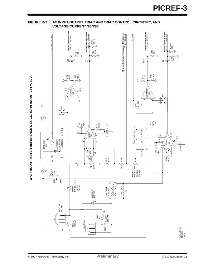
FIGURE B-3: AC INPUT/OUTPUT, TRIAC AND TRIAC CONTROL CIRCUITRY, AND VOLTAGE/CURRENT SENSE
1.0
k
+ -
8 V
AD
620
7 4
3 2
1 8
5
- 8
V
6U
2
+- 1/2
LM39
37
6 5
U5
R2
0.1
uf
0.1
uf
R5
TO
: U4
- 36
, RE
7
TO
: U4
- 6,
RA
1/A
N1
LN
AC
out
put
P2
To
Load
MT
2
MT
1
GTR
1
1 k
4.7
k
R14
R16
Z1
2A1A
85
Mag
neT
ekC
SE
187-
L
T2
R1
kwhr
_v1.
vsd
11/1
4/97
Pag
e 1
R36
A
R38
6.2
kG
= 1
4
P1
AC
inpu
t
F1
BU
SS
AG
C-1
2
Q40
10L5
Tec
cor
C9A
C10
A
C20
C21
LN
0.00
1 uf
500
VA
C
V42
0LA
1042
0 V
AC
An
alo
g C
urr
ent
Sen
se
Dig
ital
Cu
rren
t S
ense
20.0
, 1/8
W
J2
0.01
uf
C24
10 k
D12
R44
TO
: U4
- 10
RA
4
2.2
kR
9
0.01
uf
C26
D2
360
470
Zer
oC
ross
ing
Det
ect
1 2 3456
MO
C30
42U
13
N/C
N/C
5 V
R6
R10
Pha
se S
hift
Cap
acito
rs
105
k
R3
8 V
1 M
, 1%
, !/4
wP
hilip
s
5043
ED
250
VA
C
TO
: R29
2.2
ufC
28
3.83
k
+ -
AD
620 4
3 2
1 8U
1
R4
TO
: U4
- 5,
RA
0/A
N0
1.0
kR
35R37
TP
1
An
alo
g V
olt
age
Sen
se
J10.
01 u
fC
22
D10
R26
2.2
k
178.
7 k
0.00
1 uf
500
VA
C
8 V
AC
Inp
ut
Bal
ance
d /
Un
bal
ance
d S
ense
Lin
eT
O: U
4 -
11, R
A5
R36
B
1.0
k
8 V 7
5
- 8
V
6
0.1
uf
0.1
uf
C5
C19
R25
66.5
k
0.05
6 uf
0.1
uf0.
22 u
f
WA
TT
HO
UR
- M
ET
ER
RE
FE
RE
NC
E D
ES
IGN
, 50/
60 H
z, 9
0 -
264
V, 1
0 A
TO
: U4
- 52
, RG
7
4.7
kR
13D
igit
al V
olt
age
Sen
seD
11
R27
10 k
+ -
8 V
1/2
LM39
31
4
3 2U
5
8
- 8
V0.
01 u
f
C23
TP
2
1 M
, 1%
, 1/4
wP
hilip
s
5043
ED
250
VA
C1.
0 k
ã 1997 Microchip Technology Inc. Preliminary DS30452A-page 31

PICREF-3
Whm.bk Page 32 Wednesday, July 29, 1998 2:18 PM
FIGURE B-4: MICROCONTROLLER, SERIAL INTERFACE CIRCUIT, AND SERIAL EEPROM
1
0.1
UF
MCLR
0.1
UF
PIC
16C
924
19 21 24 25
26
9
65
4 3
21
64
27
U4
Vdd
22V
dd
7 23
+ 5
V D
igita
lT
O: J
4 -
BT
O: J
1 -
BT
O: J
3 -
BT
O: J
2 -
B
XT
AL
1
8 M
Hz
29
T1OSO
T1OS1
32 k
Hz
XT
AL
2
33 p
f33
pf
+ 5
V D
igita
l
RA1/AN1RA0/AN0
N/C
0.47
ufVlcd1
Avd
d
Vss
RA
3 8
RA
2
OS
C1
OS
C2
14 15 16S
DO
SD
I
RC
3
200
k
TO
: U12
- 6
68 67 66
RA
4R
A5
RB
0/IN
T
10 11 12
13
28R
C2
36RE7
60RD5
RB
7
RB
2R
B1
17 18
C1
C2
0.47
uf
Vlc
d20.
47 u
f
20V
lcd3
0.47
uf
C7
C8 C9
C15
Vss
R24
1
2
3
65
RB
3
10 K
180
K
24A
A16
/P
1 2 3 456
7
8V
cc
SC
LS
DA
A0
A1
A2
Vss
WP
U3
10 K
+ 5
v
- 8
V
Q2
2N44
03
12 K
+ 5
v
Q1
4.7
K
TX
2N39
04
9
CT
S
8
RX
P3
52
R17
R20
R21
R22
R23
TO
: R31
Tria
c C
ontr
ol, T
O: U
13-2
Dig
ital V
olta
ge S
ense
Dig
ital C
urre
nt S
ense
Ana
log
Vol
tage
Sen
seA
nalo
g C
urre
nt S
ense
+ 5
v D
igita
l
10 K
0.1
uf
S5
2 3
DT
RD
SR
RT
S
45
6
7
RS
-232
100
100
k
RB
4R
B5
RB
6
470
RN
1
470
RN
1
470
RN
1
470
RN
1RG7
910
K
R18
R19
TO
:U4-
13 R
B0
470
R
29
R48
R8
R45
R46
R32
10
k
R47
R39
100
K
100
KD
3
D4
D5
0.01
uf
10 k
1N41
501N41
50
C14
C13
C11
C12
C18
C16
C17
+ 5
v R
ef
C10
12
34
56
78
TO
U12
-1, 3
.0 V
Ref
eren
ce
100
KR
7
MC
LR
100
K
11/1
4/97
Pag
e 2
kwhr
_v1.
vsd
TO
: U5-
6
S1
ST
AR
T/S
TO
P
EN
TE
RS
3
S2
S4
TO
: R42
Circ
uit T
race
TO
: R43
Via
0.01
uf
0.01
uf
HY
BE
R
30VLCADJ
22 M
22 M
WA
TT
HO
UR
- M
ET
ER
RE
FE
RE
NC
E D
ES
IGN
, 50/
60 H
z, 9
0 -
264
V, 1
0 A
DS30452A-page 32 Preliminary ã 1997 Microchip Technology Inc.

PICREF-3
Whm.bk Page 33 Wednesday, July 29, 1998 2:18 PM
FIGURE B-5: MICROCONTROLLER AND LCD
1234567891011121314151617181920
2142
41403938373635343332313029282726252423
22
U7
VIM
-808
-DP
LCD
COM2COM3
1B, 1C1A, 1G, 1D1F, 1E2A, 2G, 2D 2B, 2C, 1DP2F, 2E, NC
3A, 3G, 3D 3B, 3C, 2DP3F, 3E,4A, 4G, 4D
4B, 4C, 3DP4F, 4E,
5A, 5G, 5D5B, 5C, 4DP
COM1
6A, 6G, 6D
6B, 6C, 5DP6F, 6E
8A, 8G, 8D
8B, 8C, 7DP8F, 8E N/C
7F, 7E7A, 7G, 7D
7B, 7C, 6DP
5F, 5E,
N/CN/C
N/CN/C
N/CN/C
N/CN/C
N/CN/C
N/C
2L
4L
6L
PIC
16C
924
59 58 57 56 55 54 53 51 50 49 48 47 46 45 44
1
636261
3132333435
37383940414243
U4
SEG01SEG00
SEG02SEG03SEG04
SEG05SEG06SEG07SEG08SEG09SEG10SEG11
SE
G12
SE
G13
COM0COM1COM2
SE
G14
SE
G15
SE
G16
SE
G17
SE
G18
SE
G19
SE
G20
SE
G21
SE
G22
SE
G23
SE
G24
SE
G25
SE
G26
N/C
11/1
4/97
Pag
e 3
kwhr
_v1.
vsd
WA
TT
HO
UR
- M
ET
ER
RE
FE
RE
NC
E D
ES
IGN
, 50/
60 H
z, 9
0 -
264
V, 1
0 A
ã 1997 Microchip Technology Inc. Preliminary DS30452A-page 33

PICREF-3
Whm.bk Page 34 Wednesday, July 29, 1998 2:18 PM
FIGURE B-6: DC POWER SUPPLY
124 3
5 6 87
T1
Mag
neT
ek F
P30
-200
470
u f
50
WV
DC
470
u f
Neu
tral
50
WV
DC
C1 C2
1
NJM
79LO
8A-N
D- 8.
0 v
U9
23
NJM
78L0
8A8.
0 v
0.01
uf
C3
U8 1
23
Dig
ital G
nd
+ +
Ana
log
Gnd
0.01
uf
C6
+ 8
V
- 8
V
To
: P2
- L
To
: P1
- N
To
: P1
- G
ND
GI W
005G
-ND
BR
1
TO
:U4
- 8
RA
2
TO
:U10
- V
in
11/1
4/97
Pag
e 4
kwhr
_v1.
vsd
unre
gula
ted
nega
tive
rail
WA
TT
HO
UR
- M
ET
ER
RE
FE
RE
NC
E D
ES
IGN
, 50/
60 H
z, 9
0 -
264
V, 1
0 A
R30
1N47
4618
V1N
4746
18 V
1N47
4618
V
Z2
Z3
Z4
68 o
hm1
W
unre
gula
ted
posi
tive
rail
DS30452A-page 34 Preliminary ã 1997 Microchip Technology Inc.
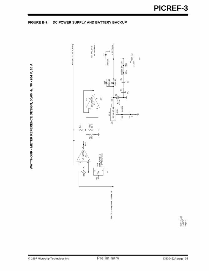
PICREF-3
Whm.bk Page 35 Wednesday, July 29, 1998 2:18 PM
FIGURE B-7: DC POWER SUPPLY AND BATTERY BACKUP
TO
: U4
- 21
, + 5
V A
nalo
g
+-8
V
1/2
LM35
8A1
432
U12
8
- 8
V
3 v
Ref
eren
ce
5.1
k
+- 1/2
LM35
8A7
56
U12
LM40
40A
IZ-5
.0
2 1
3U
11N
/C
+ 5
V R
efer
ence
Vin
R41
R40
TO
: RA
3, U
4-9
R34
1%
GN
D
Vou
tLM
2931
AZ
-5.0
5.0
v
C4
U10
+ 5
V D
igita
l
D9A
B13
v
D8
+
1N41
50D
1
C27
100
uf10
V
Vin
TO
: C1
+, u
nreg
ulat
ed p
ositi
ve r
ail
R33
11/1
4/97
Pag
e 5
kwhr
_v1.
vsd
D14
22 M
1N41
50
WA
TT
HO
UR
- M
ET
ER
RE
FE
RE
NC
E D
ES
IGN
, 50/
60 H
z, 9
0 -
264
V, 1
0 A
1N41
50
1N41
50
D6
D15
1N41
50
B2
3 v
+2.
.2 u
f
D13
D9B
1N41
50
ã 1997 Microchip Technology Inc. Preliminary DS30452A-page 35

PICREF-3
Whm.bk Page 36 Wednesday, July 29, 1998 2:18 PM
FIGURE B-8: OPTION 1: CURRENT MEASUREMENT AUTOMATIC GAIN CONTROL
11/1
4/97
Pag
e 6
kwhr
_v1.
vsd
WA
TT
HO
UR
- M
ET
ER
RE
FE
RE
NC
E D
ES
IGN
, 50/
60 H
z, 9
0 -
264
V, 1
0 A
OP
TIO
N 1
: C
UR
RE
NT
ME
AS
UR
EM
EN
T A
UT
OM
AT
IC G
AIN
CO
NT
RO
L
2A 1A
8 5
R1B
Mag
neT
ekC
SE
187-
L
T2
R1A
R1C R1D
TO
: P1-
N
TO
: TR
1-M
T1
+5
V 100
K
+5
V 100
K
+5
V 100
K
TO
: U4-
14 R
C3
TO
: U4-
8 R
A2
TO
: U4-
66 R
B7
TO
: U2-
3
X 1
0 R
ange
X 5
Ran
ge
X 2
Ran
ge
X 1
Ran
ge
DS30452A-page 36 Preliminary ã 1997 Microchip Technology Inc.

PICREF-3
Whm.bk Page 37 Wednesday, July 29, 1998 2:18 PM
APPENDIX C: FIRMWARE LISTINGPIC16C924 firmware source code was written in C andwas compiled using MPLAB-C.
Source code, and future updates, may be obtainedelectronically on the Microchip BBS and WWW site.
ã 1997 Microchip Technology Inc. Preliminary DS30452A-page 37

PICREF-3
Whm.bk Page 38 Wednesday, July 29, 1998 2:18 PM
NOTES:
DS30452A-page 38 Preliminary ã 1997 Microchip Technology Inc.

PICREF-3
Whm.bk Page 39 Wednesday, July 29, 1998 2:18 PM
APPENDIX D: PCB LAYOUT & FAB DRAWING
The top silk screen drawing for the WHM unit is shownin Figure D-1. The dimensions listed are, with respectto the orientation of this page; (horizontal dimension xvertical dimension).
Figure D-1 is the WHM unit generic silk screen andas-built schematics should be consulted for accurateinformation concerning the components of each unit.As-built schematics are provided with each unitshipped, as calibration may alter the components used.
This drawing may be obtained electronically on theMicrochip BBS or WWW site
FIGURE D-1: WATT-HOUR METER TOP SILK SCREEN
(7” x 6”)
C20
P2
1997
C9A
Z1
F1
ACOUTPUT
ACINPUT
120/240V
AC
INP
UT
/OU
TP
UT
C10A
P1
T2
CurrentSense
R1A
TR1
R6U13
R1B
TR
IAC CO
NT
RO
L
R10U11
R40
DCPOWERSUPPLY
R33R34R41
U12LED2
AC ON
J2 R49
D1
C4C27
D8
D13
D9
B1
BATTERYBACKUP
U3
U10
R38
U2
R5C21
D14
R14
R15
R16 C
28D
12C
26C24
R44
D2
R9C25U
5C
23
Cur
rent
Sen
se
DCPOWERSUPPLY
R19
Q2
R21
P3
1
R485 9
6
RE
MO
TE
CO
MM
UN
ICA
TIO
N
MCLR
S5
R47
C10
R24
R29C17
XT
AL2
C16
XT
AL1
C18
C9
C8
C7
R20
R7
R32
R23
R22
Q1R8
R46
R45
C14R17C11
D4D3
D5C12
C15R18
LED1LOAD
ON
S1 S3S2 S4
CANCEL HYBER CLR
LCDCONTROL
ENTERSTARTSTOP
VOLTAGE SENSE
US12297
U14D7 Q4
Q3D6U6
120/240 V AUTOSWITCH
T1R42
R43
R50
R2
R36
C19U1
R4
R37
R27
AN1
Z2
R3
R35
R11 R
12R
13R25
D10
J1R
26
D11
C22
C13
TP1TP2
R28
R31
R30C6
C2
U8 U9
C3
BR1
C1
Design Based on PIC16C924PICREF-3 Made in USA
DM003003
U7
R39
U4
C
Watt-Hour Meter Reference
ã 1997 Microchip Technology Inc. Preliminary DS30452A-page 39

PICREF-3
Whm.bk Page 40 Wednesday, July 29, 1998 2:18 PM
APPENDIX E: BILL OF MATERIALS (BOM)This appendix lists the Bill of Materials (BOM) for theWHM PCB. WHM schematics may be found inAppendix B.
TABLE E-1: WATT-HOUR METER (PICREF-3) BOM
Item Description ComponentPart #, Manufacturer,
Contact #Distrib #, Distributor
1 Instrumentation Amplifier U1, 2 AD620AN, Analog Devices,(617) 329-4700
Newark
2 Serial EEPROM U3 24AA16/P, Microchip Technology, (602) 786-7200
N/A
3 Microcontroller (8MHz) U4 PIC16C924 - 08I/L, Microchip Technology, (602) 786-7200
N/A
4 PLCC Socket U4-Socket PLCC 68P-T-2, McKenzie,(510) 651-2700
978-2220, Allied
5 Dual Comparator U5 LM393N, National Semiconductor, (408) 712-5800(800) 272-9959 (USA Only)
LM393N-ND, DigiKey
6 LCD, Multiplexed Display U7 VIM-808-DP-RC-S-HV,VL Electronics, Inc.,(213) 738-8700
10995-ND, DigiKey
7 3-Terminal Regulator, 8.0V, TO-92 Pkg
U8 NJM78L08A, JRC, NJM78L08A-ND, DigiKey
8 3 Terminal Regulator, Neg 8.0V, TO-92 Pkg
U9 NJM79L08A, JRC, NJM79L08A-ND, DigiKey
9 Positive 5.0V Regulator, TO-92 Pkg
U10 LM2931AZ-5.0, National Semiconductor, (408) 712-5800(800) 272-9959 (USA Only)
LM2931AZ-5.0-ND, DigiKey
10 Reference Diode, 0.1%, 5V U11 LM4040AIZ-5.0, National Semiconductor, (408) 712-5800(800) 272-9959 (USA Only)
LM4040AIZ-5.0-ND, DigiKey
11 Dual Operational Amplifier U12 LM358A, National Semiconductor, (408) 712-5800(800) 272-9959 (USA Only)
LM358AN-ND, DigiKey
12 Triac Output Optoisolator U13 MOC3042, Isocom,(214) 423-5521
MOC3042IS-ND, DigiKey
13 Metal Film Resistor, 20 W, 1%, 1/8 W
R1B 20E0MF1/4W-B 1%, Yageo,886-2-917-7555
20.0XBK, Digikey
14 Metal Film Resistor, 1 MW, 1% R2, 36 5043ED1M000F, Philips,(914) 246-2811(800) 234-7381 (USA only)
50F8317, Newark
15 Metal Film Resistor, 1 kW, 1% R3, 35 5043ED1K000F, Philips,(914) 246-2811(800) 234-7381 (USA only)
50F8302, Newark
16 Select Resistor, Alignment R4 RN60C 68.1K 1%, Dale,(402) 563-6506
58F006R 68.1K, Newark
17 Metal Film Resistor, 6.2 kW, 1% R5 Generic
DS30452A-page 40 Preliminary ã 1997 Microchip Technology Inc.

PICREF-3
Whm.bk Page 41 Wednesday, July 29, 1998 2:18 PM
18 Carbon Film Resistor, 360W, 1%, 1/4W
R6 Yageo,886-2-917-7555
360QBK-ND, DigiKey
19 Carbon Resistor, 100 kW, 5% R7, 29 Yageo,886-2-917-7555
100KQBK-ND, DigiKey
20 Carbon Resistor, 2.2 kW, 5%, 1/4W
R9, 26 Yageo,886-2-917-7555
2.2KQBK-ND, DigiKey
21 Carbon Resistor, 470W, 5%, 1/4W R10, 29 Yageo,886-2-917-7555
470QBK-ND, DigiKey
22 Carbon Resistor, 4.7 kW, 10%, 1/4W
R13, 16, 18 Yageo,886-2-917-7555
4.7KQBK-ND, DigiKey
23 Metal Film Resistor, 1 kW, 1% R14 5063JD1K000F, Philips,(914) 246-2811(800) 234-7381 (USA only)
50F8359, Newark
24 Carbon Resistor, 10 kW, 5% R17, 22, 23, 27, 28, 32, 39, 44
Yageo,886-2-917-7555
10KQBK-ND, DigiKey
25 Carbon Resistor, 910 kW, 10%, 1/4W
R19 Yageo,886-2-917-7555
910QBK-ND, DigiKey
26 Carbon Resistor, 180 kW, 10%, 1/4W
R20 Yageo,886-2-917-7555
180QBK-ND, DigiKey
27 Carbon Resistor, 12 kW, 10%, 1/4W
R21 Yageo,886-2-917-7555
12KQBK-ND, DigiKey
28 Trimmer Potentiometer, 250 kW R24 3352E-1-254, Bourns,(909) 781-5500
3352E-1-254, DigiKey
29 Metal Film Resistor, 63.4 kW, 1% R25 RN60C 63.4k 1%, Dale,(402) 563-6506
58F006R 63.4k, New-ark
30 Carbon Resistor, 68W, 5%, 1W R30 Generic
31 Metal Film Resistor, 1%, 1/4W R33 Generic
32 Metal Film Resistor, 1%, 1/4W R34 Generic
33 Metal Film Resistor, 3.83 kW, 1% R37 3K83MF-1/4W-B 1%, Yageo,886-2-917-7555
3.83KXBK, Digikey
34 Select Resistor, Alignment R38 Generic
35 Carbon Resistor, 5.1 kW, 5%, 1/4W
R40 Yageo,886-2-917-7555
5.1QBK-ND, DigiKey
36 Metal Film Resistor, 1%, 1/4W R41 Generic
37 Carbon Resistor, 100 W, 5%, 1/4W
R48 Yageo,886-2-917-7555
100QBK-ND, DigiKey
38 8-pin SIP resistor network, 470W RN1 CTS,(219) 293-7511
770-83-R 470-ND, DigiKey
39 Fast Acting Fuse, AGC 0.25 x 1.25, 12 A
F1 AGC-12, Cooper,(414) 549-5000
94F2182, Newark
40 PCB 3AG Fuse Clips F1-Clips 102074, Little Fuse,(847) 824-0400
27F1086, Newark
41 NPN Transistor, TO-92 pkg Q1 2N3904, Motorola, (602) 244-6900
2N3904-ND, DigiKey
42 PNP Transistor, TO-92 pkg Q2 2N4403, Motorola, (602) 244-6900
2N4403-ND, DigiKey
TABLE E-1: WATT-HOUR METER (PICREF-3) BOM (CON’T)
Item Description ComponentPart #, Manufacturer,
Contact #Distrib #, Distributor
ã 1997 Microchip Technology Inc. Preliminary DS30452A-page 41

PICREF-3
Whm.bk Page 42 Wednesday, July 29, 1998 2:18 PM
43 MOV, 420V AC Z1 V420LA10, Harris, (407)724-7000(800) 4 HARRIS (USA Only)
V420LA10, Newark
44 Zener diodes, 18V, 1W Z2, 3, 4 1N4746A, Motorola,(602) 244-6900
1N4746A-ND, DigiKey
45 High Speed Switching Diode, 0.5W, D0-35
D1, 3, 4, 5, 8, 9A, 9B, 13, 15
1N4150, Diodes Inc.,(805) 446-4800
Sterling
46 Schottky Barrier Rectifier, DO-41 Pkg
D2, 6, 10, 11, 12
1N5817, Diodes Inc.,(805) 446-4800
Newark
47 8 MHz Ceramic Resonator/w built in caps
XTAL1 EF0-EC8004A4, Panasonic, (714) 373-7366
PX800-ND, DigiKey
48 32 kHz Crystal Resonator XTAL2 C-001R 32.768K-A, Epson,(310) 787-6300
SE3201-ND, DigiKey
49 PC Mount Transformer T1 PF30-200, MagneTek,(219) 297-3111
DigiKey
50 Current Sense Transformer T2 CSE187-L, MagneTek,(219) 297-3111
10515-ND, DigiKey
51 Bridge Rectifier BR1 W005G-ND, General Instrument, (516) 847-3000
W005G-ND, DigiKey
52 Aluminum Electrolytic Capacitor, 470 uF, 35W VDC
C1, 2 515D477M035CG6A, Sprague,(603) 224-1961
50F072, Newark
53 Ceramic Capacitor, 0.01 mF C3, 6, 15, 22, 23, 24, 26,11,12
1C10Z5U103M050B, Sprague,(603) 224-1961
81F2060, Newark
54 Tantalum Capacitor, 100 uF, 10W VDC
C4 199D107X0010EE2, Sprague,(603) 224-1961
17F2029, Newark
55 Ceramic Capacitor, 0.1 mF C5, 13, 14, 18, 19, 20, 21
1C10Z5U104M050B, Sprague,(603) 224-1961
81F2061, Newark
56 Monolithic Ceramic Capacitor, 0.47 uF
C7, 8, 9, 10 ECU-S1J474MEB, Panasonic, (714) 373-7366
P4919-ND, DigiKey
57 Ceramic Capacitor, 0.001 uF, 500 VAC
C9A, C10A 125LD10, Sprague,(603) 224-1961
46F5228, Newark
58 Ceramic Capacitor, 33 pF C16, 17 1C10C0G330J050B, Sprague,(603) 224-1961
95F7168, Newark
59 Tantalum Capacitor, 2.2 mF, 25W VDC
C27, 28 199D225X0025AA1, Sprague,(603) 224-1961
17F2041, Newark
60 3V Lithium Battery, PCB Termi-nal Coin Type
B1, 2 CR2032, Panasonic, (714) 373-7366
P189-ND, DigiKey
61 20mm Coin Cell Lithium PC Bat-tery Holder
B1, 2-Holder 1026, Keystone,(718) 956-8900(800) 379-3943 (USA only)
1026K-ND, DigiKey
62 AC Power Line Connector - Input
P1 GSP1.3101.1, Schurter,(707) 778-6311(800) 848-2600 (USA only)
509-1269, Allied
63 AC Power Line Connector - Output
P2 4300.0251, Schurter,(707) 778-6311(800) 848-2600 (USA only)
509-1271, Allied
TABLE E-1: WATT-HOUR METER (PICREF-3) BOM (CON’T)
Item Description ComponentPart #, Manufacturer,
Contact #Distrib #, Distributor
DS30452A-page 42 Preliminary ã 1997 Microchip Technology Inc.

PICREF-3
Whm.bk Page 43 Wednesday, July 29, 1998 2:18 PM
64 Right Angle, DB9, PCB Connector
P3 DEKL-09SAT-F2, Cinch,(708) 981-6000
95F4128, Newark
65 Triac, 10 amps TR1 Q4010L5, Teccor,(214) 580-1515
Q4010L5-ND, DigiKey
66 TO-220 Heat Sink, Extruded Pins TR1-Heat Sink
531002B02500, AAVID,(603) 528-3400
HS190-ND, DigiKey
67 Momentary Switch S1, 2, 3, 4, 5 EVQ-PAD04M, Panasonic, (714) 373-7366
P8007S, DigiKey
68 Circuit Board Test Points TP1, 2 131-5031-00, Tektronix,(503) 627-5000(800) 426-2200 (USA only)
N/A
TABLE E-1: WATT-HOUR METER (PICREF-3) BOM (CON’T)
Item Description ComponentPart #, Manufacturer,
Contact #Distrib #, Distributor
ã 1997 Microchip Technology Inc. Preliminary DS30452A-page 43

PICREF-3
Whm.bk Page 44 Wednesday, July 29, 1998 2:18 PM
NOTES:
DS30452A-page 44 Preliminary ã 1997 Microchip Technology Inc.

PICREF-3
Whm.bk Page 45 Wednesday, July 29, 1998 2:18 PM
APPENDIX F: WATT-HOUR METER DEMO UNIT
This Demo Unit was designed to showcase thePIC16C924 microcontroller in a watt-hour meter appli-cation.
F.1 Demo Unit Specifications
The specifications for this demo are stated inAppendix A.
F.2 Demo Unit Assembly
A Watt-Hour Meter demo unit top view is shown in thefigure below.
FIGURE F-1: DEMO ASSEMBLY - TOP
DANGERElectrocution Hazard
Do Not Disassemble Unit
AC Input
AC Output 8-Digit LCD
Serial Port
Battery Backup
PIC16C924
Protective CoveringOf AC Electronics
Current SenseTransformer
PowerElectronics
Serial EEPROM
Push Buttons
ã 1997 Microchip Technology Inc. Preliminary DS30452A-page 45

PICREF-3
Whm.bk Page 46 Wednesday, July 29, 1998 2:18 PM
F.3 How to Set Up the Demo Unit
Follow these steps to set up the PICREF-3 Demo Unit:
1. Plug the receptacle end of a power cord into theDemo Unit “AC Input”. Plug the pronged end ofthe power cord into an AC wall socket. The ACInput will accept voltages in the 90 - 264V range.
2. Plug the load into the Demo Unit “AC Output”socket. Steady state load currents in the 0.5 -10A range can be measured. Surge currents ofup to 17A have been applied to the unit without
damage.3. Display the desired power and energy informa-
tion on the LCD display by pressing the pushbuttons (See Firmware Overview).
F.4 Recommended Loads
The following loads are recommended:
Linear Resistive Loads (Halogen lights):
• 90W• 180W• 250W• 500W• 1000W• 2000W
Linear Inductive Loads (Fractional horsepower motors):
• 230 V; 1/2 HP• 115V; 1/2, 1/3, 1/6 HP
Non-linear Loads:
• Computer monitor
FIGURE F-2: DEMO ASSEMBLY - SIDE
Note: A grounded AC power cord MUST beused for proper operation of the meter.
DANGERElectrocution Hazard
Do Not Disassemble Unit
CautionLoad current is 10A MAXIMUM.
AC InputAC Output
LCD
PowerElectronics
PIC16C924
DS30452A-page 46 Preliminary ã 1997 Microchip Technology Inc.

PICREF-3
Whm.bk Page 47 Wednesday, July 29, 1998 2:18 PM
NOTES:
ã 1997 Microchip Technology Inc. Preliminary DS30452A-page 47

Information contained in this publication regarding device applications and the like is intended for suggestion only and may be superseded by updates. No representation or warranty is given and noliability is assumed by Microchip Technology Incorporated with respect to the accuracy or use of such information, or infringement of patents or other intellectual property rights arising from such useor otherwise. Use of Microchip’s products as critical components in life support systems is not authorized except with express written approval by Microchip. No licenses are conveyed, implicitly orotherwise, under any intellectual property rights. The Microchip logo and name are registered trademarks of Microchip Technology Inc. in the U.S.A. and other countries. All rights reserved. All othertrademarks mentioned herein are the property of their respective companies.
DS30452A-page 48 ã 1998 Microchip Technology Inc.
All rights reserved. © 1998, Microchip Technology Incorporated, USA. 7/98 Printed on recycled paper.
MAMERICASCorporate OfficeMicrochip Technology Inc.2355 West Chandler Blvd.Chandler, AZ 85224-6199Tel: 602-786-7200 Fax: 602-786-7277Technical Support: 602 786-7627Web: http://www.microchip.com
AtlantaMicrochip Technology Inc.500 Sugar Mill Road, Suite 200BAtlanta, GA 30350Tel: 770-640-0034 Fax: 770-640-0307
BostonMicrochip Technology Inc.5 Mount Royal AvenueMarlborough, MA 01752Tel: 508-480-9990 Fax: 508-480-8575
ChicagoMicrochip Technology Inc.333 Pierce Road, Suite 180Itasca, IL 60143Tel: 630-285-0071 Fax: 630-285-0075
DallasMicrochip Technology Inc.14651 Dallas Parkway, Suite 816Dallas, TX 75240-8809Tel: 972-991-7177 Fax: 972-991-8588
DaytonMicrochip Technology Inc.Two Prestige Place, Suite 150Miamisburg, OH 45342Tel: 937-291-1654 Fax: 937-291-9175
DetroitMicrochip Technology Inc.42705 Grand River, Suite 201Novi, MI 48375-1727Tel: 248-374-1888 Fax: 248-374-2874
Los AngelesMicrochip Technology Inc.18201 Von Karman, Suite 1090Irvine, CA 92612Tel: 714-263-1888 Fax: 714-263-1338
New YorkMicrochip Technology Inc.150 Motor Parkway, Suite 202Hauppauge, NY 11788Tel: 516-273-5305 Fax: 516-273-5335
San JoseMicrochip Technology Inc.2107 North First Street, Suite 590San Jose, CA 95131Tel: 408-436-7950 Fax: 408-436-7955
AMERICAS (continued)
TorontoMicrochip Technology Inc.5925 Airport Road, Suite 200Mississauga, Ontario L4V 1W1, Canada Tel: 905-405-6279 Fax: 905-405-6253
ASIA/PACIFICHong KongMicrochip Asia PacificRM 3801B, Tower TwoMetroplaza223 Hing Fong RoadKwai Fong, N.T., Hong KongTel: 852-2-401-1200 Fax: 852-2-401-3431
IndiaMicrochip Technology Inc.India Liaison OfficeNo. 6, Legacy, Convent RoadBangalore 560 025, IndiaTel: 91-80-229-0061 Fax: 91-80-229-0062
JapanMicrochip Technology Intl. Inc.Benex S-1 6F3-18-20, ShinyokohamaKohoku-Ku, Yokohama-shiKanagawa 222-0033 JapanTel: 81-45-471- 6166 Fax: 81-45-471-6122
KoreaMicrochip Technology Korea168-1, Youngbo Bldg. 3 FloorSamsung-Dong, Kangnam-KuSeoul, KoreaTel: 82-2-554-7200 Fax: 82-2-558-5934
ShanghaiMicrochip Technology RM 406 Shanghai Golden Bridge Bldg.2077 Yan’an Road West, Hong Qiao DistrictShanghai, PRC 200335Tel: 86-21-6275-5700 Fax: 86 21-6275-5060
ASIA/PACIFIC (continued)
SingaporeMicrochip Technology Singapore Pte Ltd.200 Middle Road#07-02 Prime CentreSingapore 188980Tel: 65-334-8870 Fax: 65-334-8850
Taiwan, R.O.CMicrochip Technology Taiwan10F-1C 207Tung Hua North RoadTaipei, Taiwan, ROCTel: 886-2-2717-7175 Fax: 886-2-2545-0139
EUROPEUnited KingdomArizona Microchip Technology Ltd.505 Eskdale RoadWinnersh TriangleWokingham Berkshire, England RG41 5TUTel: 44-1189-21-5858 Fax: 44-1189-21-5835
FranceArizona Microchip Technology SARLZone Industrielle de la Bonde2 Rue du Buisson aux Fraises91300 Massy, FranceTel: 33-1-69-53-63-20 Fax: 33-1-69-30-90-79
GermanyArizona Microchip Technology GmbHGustav-Heinemann-Ring 125D-81739 Müchen, GermanyTel: 49-89-627-144 0 Fax: 49-89-627-144-44
ItalyArizona Microchip Technology SRLCentro Direzionale Colleoni Palazzo Taurus 1 V. Le Colleoni 120041 Agrate BrianzaMilan, Italy Tel: 39-39-6899939 Fax: 39-39-6899883
7/7/98
WORLDWIDE SALES AND SERVICE
Microchip received ISO 9001 Quality System certification for its worldwide headquarters, design, and wafer fabrication facilities in January, 1997. Our field-programmable PICmicro™ 8-bit MCUs, Serial EEPROMs, related specialty memory products and development systems conform to the stringent quality standards of the International Standard Organization (ISO).
Whm.bk Page 48 Wednesday, July 29, 1998 2:18 PM