wave phenomena on blocks — a schlieren model study
TRANSCRIPT
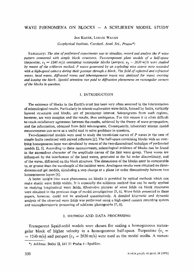
W A V E P H E N O M E N A O N B L O C K S - A S C H L I E R E N M O D E L S T U D Y
JAN KOZ£K, LUDViK WANtEK
Geophysical Institute, Czechosl. Aead. Sci., Prague*)
S u m m a r y : The aim o f performed experiments was to visualize, record and analyse the P wave pattern connected with simple block structures. Two-component plate models o f a hatf-spac.e (turpentine, v 1 = 1240 m/s) containing rectangular blocks (perspex, v 2 = 2630 re~s) were studied by means o f the schlieren method. P waves generated by an exploding wire source were recorded with a high-speed camera during their passage through a block. The f ield o f reflected and refracted waves, head waves, diffracted waves and inhomogeneous waves was analysed for waves entering and leaving the block. Special attention was paid to diffraction phenomena on rectangular corners
o f the blocks in question.
1. I N T R O D U C T I O N
The existence of blocks in the Earth's crust has been very often assumed in the interpretation of seismological results. Particularly in seismic exploration wave fields, formed by faults, vertically layered structures and blocks, are of paramount interest. Seismograms from such regions, however, are very complex and the results, thus ambiguous. For this reason it is often difficult to reach satisfactory agreement between the results, achieved by the theory of wave propagation, and the information, obtained from field seismograms. Consequently, laboratory seismic model measurements can serve as a useful tool to solve problems in question.
Two-dimensional models were used to study the travel-time curves of P waves in the case of simple faults combined with curved reflectors [I]. The half-space containing blocks with an over- lying homogeneous layer was simulated by means of the two-dimensional technique of perforated models [2, 3]. According to these measurements, seismological evidence of blocks can be found in the anomalous character of the amplitude curves of the first wave group. These waves are influenced by the interference of the head waves, generated at the 1st order discontinuity, and of the waves, diffracted on the block structure. The dimensions of the blocks must be comparable to, or greater than the wavelength of the incident wave. Analogous results were obtained on three- dimensional gel models, simulating a step change at a plane 1st order discontinuity between two homogeneous layers [4].
A better insight into wave phenomena on blocks is provided by optical methods which can make elastic wave fields visible. It is especially the schlieren method that can be easily applied to studying longitudinal wave fields. Illustrative pictures of wave fields on block structures were obtained in the previous stage of model investigations [5, 6]. Wave fields presented in these papers, however, could not be analysed quantitatively. A detailed kinematic and dynamic analysis of the observed wave fields was performed using a high-speed camera recording system and microphotometric processing of schlieren photographs [7, 8].
2. M E T H O D A N D D A T A PROCESSING
T r a n s p a r e n t l iqu id - so l id mode l s were chosen fo r scal ing a h o m o g e n e o u s rec tan-
gu la r b lock o f h ighe r ve loc i ty in a h o m o g e n e o u s ha l f -space . T u r p e n t i n e @i =
= 1240 m/s ) a n d pe r spex (v2 = 2630 m/s ) were used as t he m o d e l media . A rec tan -
*) Address: Bo~ni II, 141 31 Praha 4 - Spo[ilov.
3 5 0 Studia geoph, et geod. 19 [1975]

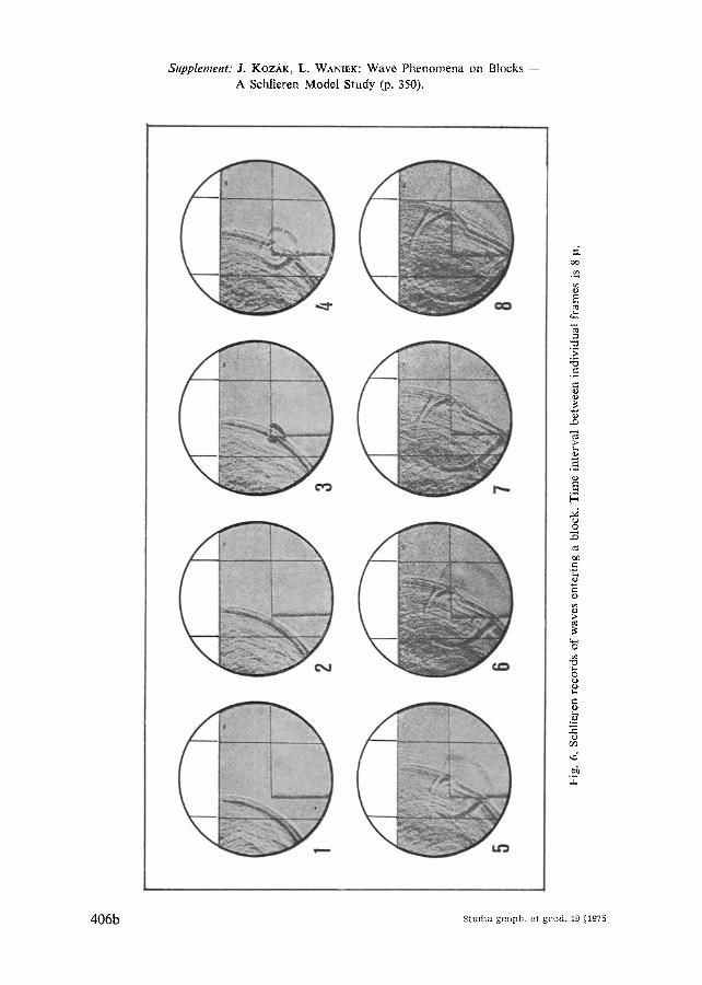
Supplement: J. Koz/~K, L. WANtEK: Wave Phenomena on Blocks -- A Schlieren Model Study (p. 350).
:J. oo
¢.,
e'~
E
g~
e4
S t u d i a geoph, et g e o d . 19 I19751 406a
;z¢
can
~'ig
. 6.
Sch
lier
en r
eco
rds
of
wav
es e
nte
rin
g a
blo
ck.
Tim
e in
terv
al b
etw
een
indi
vidu
al f
ram
es i
s 8
la.
e~ i; O
O I

Wave Phenomena on B l o c k s . . .
gular perspex pla te (700 x 150 x 24 ram) was loca ted at the b o t t o m of a special
model l ing vessel (1100 x 400 x 25 mm). One o f the rec tangular corners of the
perspex pla te coincided with the centre o f the t r ansparen t w indow of the model l ing
vessel. F ina l ly , the turpent ine was pou red over the perspex p la te to fo rm a layer
66 m m thick (Fig. 1).
a
................ f ]
100mm~
b
Fig. 1. Arrangement of model experiments: a - for waves leaving a block, b -- for waves entering a block, S - source, 1 -- turpentine (vi = 1240 m/s). 2 - perspex (v 2 = 2630 m/s),
in the circular transparent window of the model vessel the distance of 100 mm is marked.
In order to visualize P wave fields in the treated models, the IAB-451 schlieren apparatus, working with a parallel beam of light, was used. Elastic waves in the model were generated by an exploding wire (predominant frequency 0"3 MHz) which was located on the model surface. For the recording the schlieren wave fields the high-speed camera SFR-2 with an operating rate of 2.5 mil. frames per second was applied.
The high speed-camera records, consisting of 30 schlieren frames delayed 4 ~ts in time, enabled the study of the kinematics of the wave fields and the construction of travel-time curves for all the wave groups visualized in the model. Two vertical mark lines in the field of observation defined the distance of 100 mm.
The dynamic properties of the recorded waves were investigated microphotometrically by evaluating the transparent high-speed camera records. For this evaluation the automatic MARK III-CS double-beam recording microdensitometer, operating with a linear density scale, was chosen. Densitometric profiles were traced in all cases perpendicularly to the wave fronts investi- gated. The obtained densitograms were used for plotting the amplitude curves of the wave groups under study.
A deta i led descr ip t ion o f the a r rangement o f the exper iment and the way o f
eva lua t ing the schlieren records for bo th the k inemat ic and dynamic analysis o f the
wave groups , represented on the schlieren records , is given in [8].
3. RESULTS
Studying wave fields connected with b locks o f h igher velocity in an elastic half-
space, two basic s i tuat ions can be dis t inguished: waves enterning, and leaving a b lock .
U n d e r ac tua l condi t ions , however , a superpos i t ion o f bo th these s i tuat ions is p robab le .
The mode l exper iments enable to separa te bo th the effects, men t ioned above (Fig. 1).
Stuclia geoph, et geod. 19 [1975] 351

& Koz~k, L. Waniek
3.1 W a v e s L e a v i n g a B l o c k
The selected sequence o f schlieren photographs in Fig. 2 (see S u p p l e m e n t p. 406a)
shows P waves leaving the block. The picture o f the wave field before leaving the block
corresponds to that o f a plane 1st order discontinuity between a homogeneous layer
over a half-space o f higher velocity (Fig. 3a). Therefore, the observed wave groups are
a
/ b
S
\\ h' / /
/ ....
Fig. 3. Denotation of wave groups observed in the wave field before (a)
and after (b) leaving the block. S -- source, P1 -- direct wave, P I P~ -- reflected wave, Pi PI Pt -- from the surface reflected P t P i
wave, P~2 -- refracted wave, P I 2 I - - head wave, P12(1) -- re- fracted wave P i2 after leaving the
Nock, P~ z -- inhomogeneous wave, Di, D2, D12 -- diffracted waves, D21 -- head wave generated by the
diffracted wave D z.
denoted in the usual way: P I - direct wave, P 1 P I - reflected wave, P lz - refracted wave, P~21 - head wave and P12 - inhomogeneous wave [9]. The wave field, after
leaving the block, becomes more complex (Fig. 3b). Besides the wave groups mentioned above, a set o f waves o f diffractive origin can be observed in the
schlieren pictures obtained: D12 - diffracted wave connecting the wave fronts
o f the former refracted wave Plz(~) and the former head wave P12~, D~ and D z -- diffracted waves, generated by the P t wave reaching the block corner, propagat ing as spherical P waves in both the model media with the corresponding
352 Studia geoph, et geod. 19 [19751

W a v e P h e n o m e n a on B l o c k s . . .
velocity Vp and, finally, secondary head waves Dal in the medium of lower velocity. Some characteristic features of the recorded wave groups can be derived by
analysing the individual frames.
a) Good transmission of the refracted wave Plz into the half-space at the vertical boundary of the block is quite evident. In the medium of higher velocity neither reflected nor diffracted waves are visible (see frames 2 - 4 in Fig. 2).
After leaving the Mock, a new homogeneous wave front composed of the former refracted wave P12 and of the head wave P12i is created. The continuity of these wave fronts in the diffraction zone is given by the existence of the D~2 wave of the same phase (see frames 3 - 8 in Fig. 2).
Fig. 4. Amplitude pattern of the diffracted wave D12 connecting the P12 and Ptz(~) waves after leaving the block. I -- half-space, 2 -- block, ~ -- azimuth of measurements, A -- amplitude in units of optical density D.
c'q /'/riO"
Selected schlieren photographs were used for the microphotometric evaluation of the amplitude distribution in the front of the D12 wave. In the series of 4 subsequent frames the D12 wave was treated microphotometrically after its passage through the block under different angles as shown in Fig. 4. The cosine correction, corresponding to the angle between the measured profiles and the direction of the linear schlieren knife, was introduced. The average normalized amplitude pattern in the wave front was plotted in the diagram. Hence, it follows that the diffraction zone between 0 ° and 60 ° is characterized by a well pronounced minimum in the amplitude pattern. It should be pointed out that in the diffraction region the amplitude cannot be com- puted even if the exact ray theory is used.
b) The rectangular corner of the block, after being touched by the direct wave Pt, creates a new point source of two diffracted waves D1 and D 2 propagating in both media. (See frames 6 - 8 in Fig. 2.)
Whilst the wave /)1 has its assumed spherical wave front, the shape of the D 2 wave is unexpected asymmetric (see frames 7 - 8 in Fig. 2). In Fig. 5 travel-time measurements along both the vertical (curve 3) and horizontal (curve 2) edges of the block are presented. Except for the vicinity of the block corner, the velocity is constant and corresponds to the v v velocity in the block (v 2 = 2630 m/s). The velocity
Studia geoph, et geod, 19 [1975] 3 5 3

J. Kozdk, L. Waniek
increase near to the corner in the vertical direction (dashed part of curve 3) is probably
caused by the non-uniform energy distribution in the wave front of the diffracted wave D 2. According to similar model experiments, the geometry of the Dz wave front varies with the angle of incidence of the P~ wave, touching the block corner.
This wave phenomenon is now being studied.
I
125 186
t (psi
A
166
146
. i 126
}I, X, I[mm)
150 175 200
172 ~
./ IW- -7L- 3O t d
: / / 2 / " ~5-, / cps,
I 1 / " - ~ ' ~ I I ',', . / . . . ~ > ' 7 ° ~ - I
- ~ 2 . ' o + 25 ~o ~ 1oo
/'4
Fig. 5. Travel-time curves of the diffracted wave D 2. 1 -- travel-time curve of the P1 wave along a profile close to the horizontal block boundary (t -- travel-time of the Pt wave, x 1 -- distance along the block boundary), 2 -- travel-time curve of the D 2 wave along the horizontal block boundary, 3 -- travel-time curve of the D 2 wave along the vertical block boundary (t a -- travel-
time of the D 2 wave, x 2 -- distance from the block corner).
The diffracted D 2 waves forms secondary head waves D21 in the medium of lower velocity. In accordance with the energy distribution in the D 2 wave also the head
wave D2a, propagating along the vertical block boundary, is more intensive than the D21 wave along the horizontal boundary. As a consequence of the variable velocity of the Dz wave in vertical direction (curve 3 in Fig. 5), the wave front of the
corresponding D z t wave is curved.
c) At the horizontal block boundary a relatively intensive inhomogeneous wave Pl z
is generated by the P1 wave (see frames 1 - 6 in Fig. 2). This wave propagates in the lower medium with a velocity of about 800 m/s.
d) The wave pattern of the system of the direct wave P~ and reflected wave P I P ~
does not change its shape substantially after leaving the block. These waves propagate in the homogeneous half-space along a hypothetical boundary without significant changes in their intensity. Thus, seismic measurements on the surface will not be able to prove unambiguously for a long time the interruption of a plane boundary (see frames 7 - 8 in Fig. 2).
3.2 W a v e s E n t e r i n g a B l o c k
Schlieren photographs recording the entrance and passage of P waves through a rectangular block of higher velocity are demonstrated in Fig. 6 (see S u p p l e m e n t
554 studia geoph, et geod. :S [1975]
Wave Phenomena on Blocks...
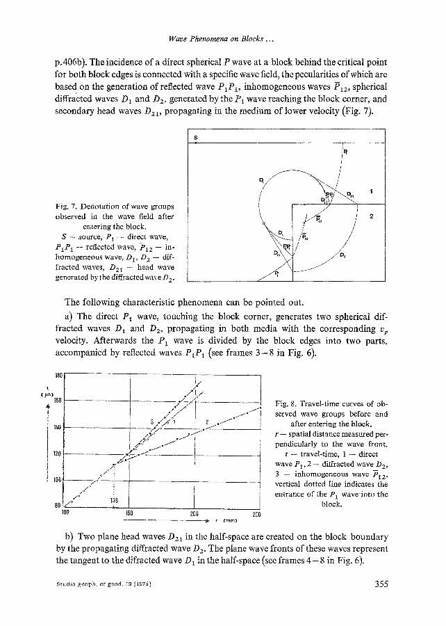
p. 406b). The incidence of a direct spherical P wave at a block behind the critical point
for both block edges is connected with a specific wave field, the pecularities of which are
based on the generation of reflected wave P1P1, inhomogeneous waves P~2, spherical diffracted waves D1 and D2, generated by the P1 wave reaching the block corner, and
secondary head waves D z l, propagating in the medium of lower velocity (Fig. 7).
Fig. 7. Denotation of wave groups observed in the wave field after
entering the block. S - source, Pi -- direct wave,
P1Pi - - reflected wave, lsI2 - - in- homogeneous wave, DI, D 2 -- dif- fracted waves, D21 -- head wave generated by the diffracted wave D 2.
i
\ ........... / 7
The following characteristic phenomena can be pointed out.
a) The direct P1 wave, touching the block corner, generates two spherical dif- fracted waves D1 and D2, propagating in both media with the corresponding vp velocity. Afterwards the P i wave is divided by the block edges into two parts,
accompanied by reflected waves PiP1 (see frames 3 - 8 in Fig. 6).
180
t ~ps)
100 - -
140
120
l .,<,/j " : / > "
100 i
80 I/J"J° 138 o z 100
. / ° I / /* / o ~ - - -
P / ° 1 J ~ "
/ . /
,'-~° /
150 200 250 r (rnrn)
Fig. 8. Travel-time curves of ob- served wave groups before and
after entering the block. r -- spatial distance measured per- pendicularly to the wave front.
t -- travel-time, 1 -- direct wave P1,2 -- diffracted wave Dz, 3 -- inhomogeneous wave P12, vertical dotted tine indicates the entrance of the PI waveinto the
block.
b) Two plane head waves O21 in the half-space are created on the block boundary by the propagating diffracted wave D 2. The plane wave fronts of these waves represent the tangent to the difracted wave D~ in the half-space (see frames 4 - 8 in Fig. 6).
Studia geoph, et geod. 19 [1975] 355

J. Kozdk, L. Waniek
c) The direct P1 waves, propagating along the horizontal and vertical block boundary, generate relatively intensive, almost plane inhomogeneous waves P~=
(see frames 5 - 8 in Fig. 6).
A (D)
30
100 150 200 250 a
A (D)
30
15 ?--
1 2
3__.
\ , , _ s •* ~ -
J 100 150 b 200 250
• r (ram)
Fig. 9. Amplitude-distance curves of observed waves before and after entering the block, a - amplitude curve of the P1 wave close to the surface, b -- amplitude curves of the diffracted wave D 2 and inhomogeneous wave Pie- r - spatial distance measured perpendicularly to the wave front. A -- amplitude in units of optical density D, t -- propagation in the half-space, 2 -- propagation in the block. On the right hand side of the figures directions of the micro-
photometric profiles are shown schematically.
d) The kinematics of the recorded wave groups is given in Fig. 8. The travel-time curves were constructed by means of the spatial location of the investigated wave groups, recorded in the individual schlieren frames (delayed in time by 4 Its) along the profiles shown in Fig. 9. The travel-time curve of the direct wave P1 (curve 1 in Fig. g) can be plotted over the whole epicentral distance range; the evaluated velocity v 1 = 1240 m/s (turpentine). The travel-times of the diffracted wave D12 (curve 2 in Fig. 8) correspond to the velocity of perspex representing the block (v2 = 2630 m/s). Curve 3 in Fig. 8 denotes the travel-time curve of the inhomogeneous wave P~z- The resulting velocity of 1050 m/s of this wave is lower than that of the P1 wave in the half-space. Owing to the slightly varying curvature of these waves,
3 5 6 Studia geoph, et geod. 19 [1975]

Wave Phenomena on Blocks ...
it should be pointed out that the observed velocity depends on the direction in which
the onset o f the wave was measured.
e) In F ig .9 the amplitude-distance curves o f the investigated wave groups are given.
The amplitudes o f the direct P1 wave were measured close under the surface (Fig. 9a).
The shape o f the amphtude curve seems to reflect sensitively the existence o f an
underlying block by changing the amplitude decay. The point o f flexion is well
p ronounced and shifted to a greater epicentral distance due to the curvature o f the
P~ wave front. The pecularities o f the amplitudes inside the block are demonstra ted
in Fig. 9b. Here the amplitude-distance curves o f the diffracted waves D 2 and of the
inhomogeneous wave P~2 are given. The at tenuation o f both wave groups is quite
different. According to model results, the inhomogeneous wave P~2 becomes the
mos t intensive wave group in the block with increasing distance.
Summarizing this paper we can say that even for the simplest model o f a block
structure in an homogeneous half-space, the pat tern o f P wave fields can be classified
as very complex. Under actual conditions, however, where a superposition o f all the
observed effects can be assumed, the existence o f a block can be evidenced on the
basis o f a dense network of seismological observations only. Both, kinematic and
dynamic parameters of the observed wave groups must be studied in detail.
Acknowledgements: The authors appreciate the discussions with Doc. Dr. V. (~erven3~ and Dr. J. Van~k during the course of the interpretation of the results obtained. They are indebted to Mrs. N. Pickov~ and Mr. O. Soj ka for their kind co-operation in performing the experiments and processing the results.
Received 16. 11. 1974 Reviewer: V. Cervenj,
References
[1] F. A, A n g o n a : Two-dimensional modelling and its application to seismic problems. Geo- physics, 25 (1960), 468.
[2] A. F. ABepr, ai~oB: MoJxeJ~poBanrm cpeJl c 6~OKOBO~ crpyKTypo~ tta ~bIp~aTsIX JmcTax. FI3B. AH CCCP, ~H3. 3eua~, Ho 2 (1968), 88.
[3] A. F. ABep~,~rIOB: CegtcMa~ezKoe Mo~e~rIpoBanne C3IOftCTOft cpe~l~,l c 6noKo~. II3B. AH CCCP, q)rt3. 3eM.rr~i, Ho 4 (1969), 86.
[4] K. Cidlinsk3~: K interpretaci seismick?~ch m~[en[ p~i metod6 vrtni refrakce. Disert., Karlova Univ., Praha 1969 (not published).
[5] F. Vosah lo : Fortschritte beim Impuls-Schlieren-Verfahren, einem Hilfsmittel geophysika- lischer Forschung und Praxis. Freiberger Forschungsh., C 45 (1958), 62.
[6] A. ur R a h m a n : Untersuehung der Ausbreitung yon WeUen in Modellen geologischer K6rper mit der Methode der Schlierenoptik. Dissert., Ludwig-Maxmilian-Univ., Mtinchen 1963.
[7] J. Kozhk, L. Waniek: Schlierenoptische Untersuchungen an seismischen GelmodeUen mit photometrischer Auswertung des Wellenfeldes. Z. Geophys., 26 (1970), 175.
[8] J. Koz~lk: Kinematic and Dynamic Properties of Elastic Waves Investigated on Seismic Models by means of the Schlieren Method. Travaux Inst. G6ophys. Acad. Tch6cosl. Sci. No 354, Geofysik~ilni sbornik 1971, Academia, Praha 1973.
[9] V. (~erven~, J. Koz~ik: Head Waves from Curved Interfaces. Travaux Inst. G~ophys. Acad. Tch6cost. Sci. No 370, Geofysik~ini sbornik 1972, Academia, Praha 1974.
Studia geoph, et geo0. 19 [1975] 357