wave propagation theory - testing deep foundations · wave propagation theory - testing deep...
TRANSCRIPT

Wave Propagation Theory -
Testing Deep Foundations
Testing Deep Foundations
Using the Wave Propagation
Theory

Wave Propagation Theory -
Testing Deep Foundations
What we will cover
Some of the different Non-Destructive Testing (NDT) techniques that utilize the Wave Propagation Theory
A brief introduction to Wave Propagation Theory and how it works for foundation testing
Some real world examples

Wave Propagation Theory -
Testing Deep Foundations
Several NDT techniques utilize Wave Propagation Theory, including
Standard Test Method for Integrity Testing of Concrete Deep Foundations by Ultrasonic Crosshole Testing (ASTM D 6760-08)
Standard Test Method for Low-Strain Impact Integrity Testing of Deep Foundations (ASTM D 5882-07), and
Standard Test Method for High-Strain Dynamic Testing of Piles (ASTM D 4945-00)

Wave Propagation Theory
Theory (part 1)
A stress wave travels through a uniform material at a predictable rate (wave speed).
The wave speed for structural steel is 16808 feet per second (fps), > 3 miles per second.
The wave speed for normal concrete/grout is about 13,000 fps, but varies based upon strength, elastic modulus, unit weight, etc.

Crosshole Sonic Logging
“Integrity Testing of Concrete Deep Foundations by Ultrasonic Crosshole Testing” (ASTM D 6760-08)
Generally used for fairly large diameter drilled shafts.
tubes are placed along the length of the shaft prior to concrete placement.
After the concrete sets you measure the time for a stress wave produced in one tube to travel to another, (a known distance)
If the time is different than expected, it indicates that something other than intact concrete is present between the points.

Crosshole Sonic Logging
4 Tubes gives you 6 paths to check, more tubes more paths
Crosshole Sonic Logging
By evaluating the time required for the stress wave to travel the various paths you can estimate the location and extents of potential problems

Crosshole Sonic Logging
8 tubes gives you 28 paths to check
Wave Propagation Theory
Theory (part 2)
For the Ideal, uniform totally unsupported pile, a vertical stress wave produced at the top of a pile would travel essentially unchanged to the toe.

Wave Propagation Theory
F=ma As a force travels down a pile,
the force is balanced by the mass
times the acceleration required to
move the next individual element.
Note: The nature of the moving
stress wave front makes the
situation more complex, but the
Free Body Diagram can be used
to illustrate what happens.
ma
F
Free Body Diagram

Wave Propagation Theory
At hard bearing on bedrock, the mass of the next element becomes infinite, but the acceleration goes to zero, so ma goes to zero. In order to maintain a force balance, an upward traveling compressive wave is produced. Inertia, it takes a new force to stop the pile.
Downward Traveling
Compression Wave
Upward Traveling
Compression Wave

Wave Propagation Theory
At a free toe, the only way to balance the force is through tension from the pile above. A downward traveling compression wave turns around and becomes an upward traveling tension wave. Can be thought of as inertia, once the pile is moving it wants to keep moving.
Downward Traveling
Compression Wave
Upward Traveling
Tension Wave

Wave Propagation Theory
Using the same ideas, it can be shown that a change of mass along a pile shaft, to something between zero and infinity, will produce a partial reflected wave, while the remainder of the wave
continues on.
A decrease in the pile mass (necking) will produce a partial reflected tension wave.
An increase in the pile mass (bulging) will produce a
partial reflected compression wave.

Pile Integrity Testing (PIT)
“Low Strain Impact Integrity Testing of Deep Foundations” (ASTM D 5882-07)
Called Pile Integrity Testing (PIT)
It is also called Low Strain Testing, Impact Testing, Pulse/Sonic Echo, Impact/Transient Response, and other names.
PIT is not a load test, no estimate of bearing capacity is possible.
PIT only indicates the uniformity (integrity) of a deep foundation.
Pile Integrity Testing (PIT)
For PIT we produce a compressive stress wave at the top of the pile (using a hand held hammer) and then measure the reflected wave that returns, with an accelerometer.
As a stress wave travels down a pile, reflected partial waves can be produced at changes in the pile cross section, and from the toe.
Pile Integrity Testing (PIT)
Knowing the wave speed and the time from impact for the reflected wave to returns to the top of the pile, we can calculate where the returning wave was created, whether from the toe or from some anomalyalong the shaft.
Analyzing the type of returning wave (compression or tension) and the relative strength of the wave, we can estimate the amount of necking or bulging that created that wave.

Wave Propagation Theory
Theory (part 3)
Until now, the energy being applied to the piles have been small, enough to set up a stress wave in the material, but not enough to actually move the pile.
If we apply enough energy to move the pile, additional reflected waves can be produced.
Wave Propagation Theory
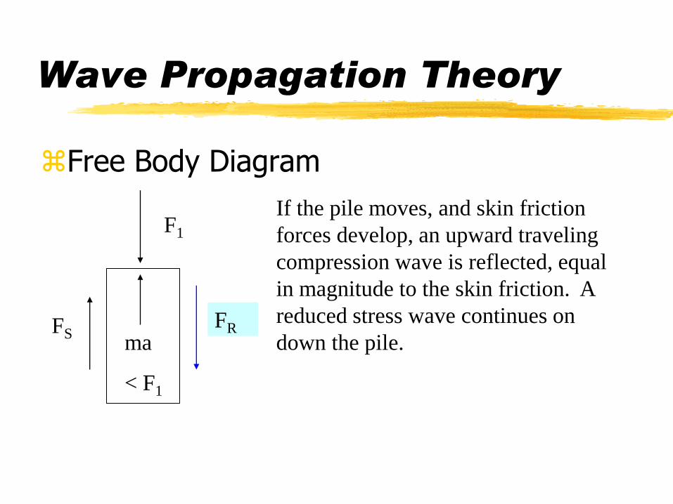
Free Body Diagram
If the pile moves, and skin friction
forces develop, an upward traveling
compression wave is reflected, equal
in magnitude to the skin friction. A
reduced stress wave continues on
down the pile.
F1
ma
< F1
FSFR

Dynamic Pile Load Testing
Standard Test Method for High-Strain Dynamic Testing of Piles (ASTM D 4945-00)
Dynamic Pile Load Testing is performed during actual pile driving, during initial drive, and/or during restrike.
Dynamic Pile Load Testing provides an estimate of the actual pile load capacity in real time.
Dynamic Pile Load Testing also provides information about the pile integrity, and the hammer operation

Dynamic Pile Load Testing
For Dynamic Pile Load Testing we mount accelerometers and strain gages on the pile and obtain reading during pile driving.
From the strain gages we measure the strain in the pile and calculate the stress (and then the force) - whether from the hammer impact or from reflected stress waves.
From the accelerometers we can calculate the velocity and then the displacement of the pile, over time during the blow event (initial impact and the resulting reflected waves).
Therefore we know the stress being applied to the pile and the reaction of the pile to that force for each blow.

Dynamic Pile Load Testing
By looking at the initial impact information, we can evaluate the hammer operation.
By analyzing the returning stress wave, we can obtain estimates of skin friction (including the distribution along the shaft) and end bearing.
By evaluating the progressing, with a record of the blows per foot (or inch), we can determine the required blow count to achieve the target capacity.

Wave Propagation Theory -
Testing Deep Foundations
Some Real World Examples