wave rotor-enhanced gas turbine engines - nasa · wave rotor-enhanced gas turbine engines ... disk,...
TRANSCRIPT

NASA Technical Memorandum 106998 AIAA-95-2799
Army Research Laboratory Technical Report ARL-TR -806
Wave Rotor-Enhanced Gas Turbine Engines
Gerard E. Welch Vehicle Propulsion Directorate U.S. Army Research Laboratory Lewis Research Center Cleveland, Ohio
Scott M. Jones and Daniel E. Paxson Lewis Research Center Cleveland, Ohio
Prepared for the 31st Joint Propulsion Conference and Exhibit cosponsored by AIAA, ASME, SAE, and ASEE San Deigo, California, July 10-12,1995
National Aeronautics and Space Administration RESEARCH LABORATORY
https://ntrs.nasa.gov/search.jsp?R=19950024096 2018-06-30T17:58:21+00:00Z

Wave Rotor-Enhanced Gas Turbine Engines
Gerard E. Welch*, Scott M. Jonest, Daniel E. Paxson* NASA Lewis Research Center
21000 Brookpark Road, MIS 77-6 Cleveland, OH 44135
Abstract The benefits of wave rotor-topping in small (400 to
600 hp-class) and intermediate (3000 to 4000 hp-class) turboshaft engines, and large (80,000 to 100,000 lb, class) high bypass ratio turbofan engines are evaluated. Wave rotor performance levels are calculated using a one-dimensional design/analysis code. Baseline and wave rotor-enhanced engine performance levels are obtained from a cycle deck in which the wave rotor is represented as a burner with pressure gain. Wave rotor-topping is shown to significantly enhance the specific fuel consumption and specific power of small and intermediate size turboshaft engines. The specific fuel consumption of the wave rotor-enhanced large turbofan engine can be reduced while operating at significantly reduced turbine inlet temperature. The wave rotor-enhanced engine is shown to behave offdesign like a conventional engine. Discussion concerning the impact of the wave rotor/gas turbine engine integration identifies tenable technical challenges.
Introduction Wave rotor topping units can significantly enhance
the performance levels of gas turbine engines. 1-7 NASA Lewis Research Center is currently characterizing the performance of wave rotorsS-1I with an aim toward applying wave rotor technology to increase the specific power, and decrease the specific fuel consumption, of turboshaft and turbofan engines. 12 The benefits of wave rotor-topping in small (400 to 600 hp-class) and intermediate (3000 to 4000 hp-class) turboshaft engines, and large (80,000 to 100,000 lb,class) high bypass ratio turbofan engines are evaluated in this paper. The wave
*Aerospace Engineer, U.S. ARMY Research Laboratory, Vehicle Propulsion Directorate; Member AIAA.
tAerospace Engineer, Aeropropulsion Analysis Office. *Aerospace Engineer, System Dynamics Branch, Member AIAA.
Copyright c 1995 by the American Institute of Aeronautics and Astronautics. Inc. No copyright is asserted in the United States under Title 17. U.S. Code. The U.S. Government has royalty-free license to exercise all rights under copyright claimed herein for Government purposes. All other rights are reserved by the copyright owner.
1
rotor component and its performance is first described. Calculated estimates of the wave rotor-enhanced specific power and specific fuel consumption for the three engine classes are then provided using wave rotor point design performance levels in a system deck. Lastly, preliminary comments on the impact of wave rotor/engine integration are offered.
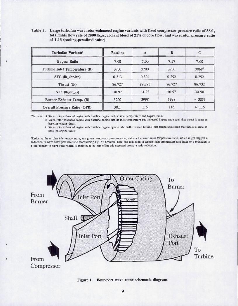
Wave Rotor Description The wave rotor is an internal flow device designed to
efficiently exchange energy between gas streams of differing energy density. The energy exchange is accomplished within shrouded rotor passages (see Fig. 1) by shock and expansion waves which propagate axially along the passages. The unsteady waves are initiated as the rotor passages open and close to the steady-state flows in the inlet and exhaust ports in a timed sequence dictated by the rotor speed and port azimuthal positions. In general, the wave rotor passages are alternately exposed to cold and hot gases at frequencies much higher than the reciprocal of the thermal time constant of the rotor walls (hub, shroud, and blades) and, therefore, the rotor assumes a mean temperature significantly lower than the peak gas temperature in the rotor. This self-cooling feature enables topping in turbine inlet temperature-limited gas turbine engines; i.e., the wave rotor-topping increases the pressure and temperature at which heat is added in the burner without increasing the temperature of the engine turbomachinery components. An historical overview and detailed description of the wave rotor is presented in Ref. 13.
Configuration The number and azimuthal location of the wave rotor
ports are set to effect various thermodynamic cycles. For example, three-port wave rotors have been used to divide an inlet medium total pressure stream into two output streams, one of total pressure higher than the inlet stream and one with total pressure lower than the inlet (e.g., see Refs. 8 and 14). No heat is added in the three-port cycle; rather, a fraction of the inlet gas is compressed by the energy of the remainder which is expanded. In an analogous manner, two streams of

high and low pressure gas can be joined into one of intermediate pressure. 14 Other examples include fourport machines which have been marketed as superchargers (i.e., as bottoming cycles) to enhance the specific power of internal combustion engines. IS The wave rotor was first applied as a gas generatorl3 (e.g., see the wave rotor topped locomotive engine reported in Ref. 1).
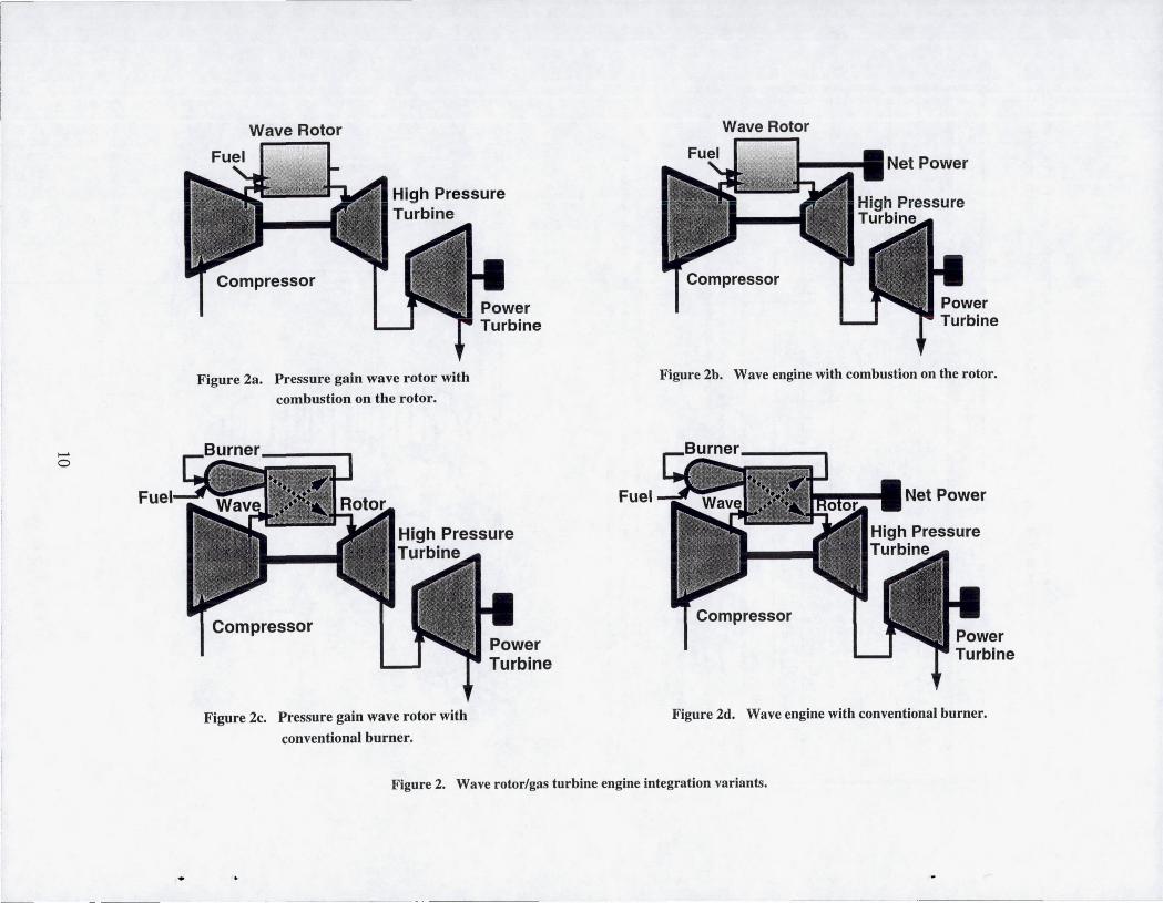
Various port configurations and heat addition schemes can be envisaged to effect the Brayton cycle of interest to the present work-some of the more simple ones are shown schematically in Figs. 2a-2d.
Heat addition. Some investigators (e.g., Ref. 2) have suggested combustion internal to the wave rotor passages as shown schematically in Figs. 2a and 2b. In this approach, two ports (with ductwork denoted by the arrows) are required per cycle, one from the compressor and one to the turbine. Conceptually the wave rotor replaces the burner of the conventional engine; however, combustion internal to the rotor introduces potential problems related to fuel addition, ignition, and available combustion time and is still in a conceptual stage. Work in this area is ongoing. 16
Alternatively to combustion on-board the rotor, heat can be added in a conventional burner, external to a wave rotor which has four ports as shown in Figs. 2c and 2d. In these variants, an extra component (the wave rotor) and three ducts per cycle-from the compressor, to the turbine, and to the burner-are added to the engine. The external burner approach is attractive in that heat addition is accomplished using existing, burner technology; however, the addition of high temperature ducting poses challenges to engine layout and thermal load management.
Power Extraction. Wave rotor blades can be canted and shaped so as to use the gas dynamic waves for energy exchange while also changing the tangential momentum of the flux entering and leaving the rotor, thus producing shaft power. 17 The "wave engine" approach is shown schematically in Figs. 2b and 2d. The wave engine introduces essentially anew, high tip speed, likely off-axis, (albeit self-cooled) power turbine into the engine and in this way complicates the design. Conceptually, a baseline engine can be back-fit to operate with high pressure turbine (HPT) and low pressure turbine (LPT) temperature and pressure ratios and corrected flow identical to those in the un-topped baseline engine. HPT cooling would come from the high pressure compressor as in the baseline engine; therefore, an attractive feature of the wave engine approach is that the net power produced in the" topping
2
stage is extracted from the top part of the cycle so that the baseline engine is essentially unmodified. Alternatively, the pressure gain wave rotor (Figs. 2a and 2c) has straight rotor blades and zero shaft power output by design. The net power available, from the wave rotor-topping is made manifest to the engine through the pressure gain across the wave rotor; i.e., the HPT inlet pressure is significantly higher than the compressor discharge pressure-rather than lower by the burner pressure drop as in the baseline engine. This approach is attractive in that conventional turbomachinery is used to extract the extra available net power. Because net power is not produced by the wave rotor, the rotor speed is set by the wave timing and performance optimization. The rotor corrected tip speeds are therefore relatively low (typically 250 to 300 fils), giving rise to relatively low mechanical stress levels. Windage, disk, and bearing friction losses are overcome by a small drive motor or, in practical application, by introducing pre-swirl through the inflow port ducts required to maintain rotor speed (after Ref. 18). The corrected flow in components downstream of the wave rotor is reduced and, because the HPT inlet is at a pressure higher than the compressor discharge, film cooling in the first nozzle and first rotor of the HPT must come from the wave rotor. The present work considers only the four-port pressure gain wave rotor with heat addition in a conventional burner, external to the wave rotor (Fig. 2c). The four-port pressure gain wave rotor is a future NASA LeRC research vehicle and is presently considered amenable to system integration within current engine design philosophy.
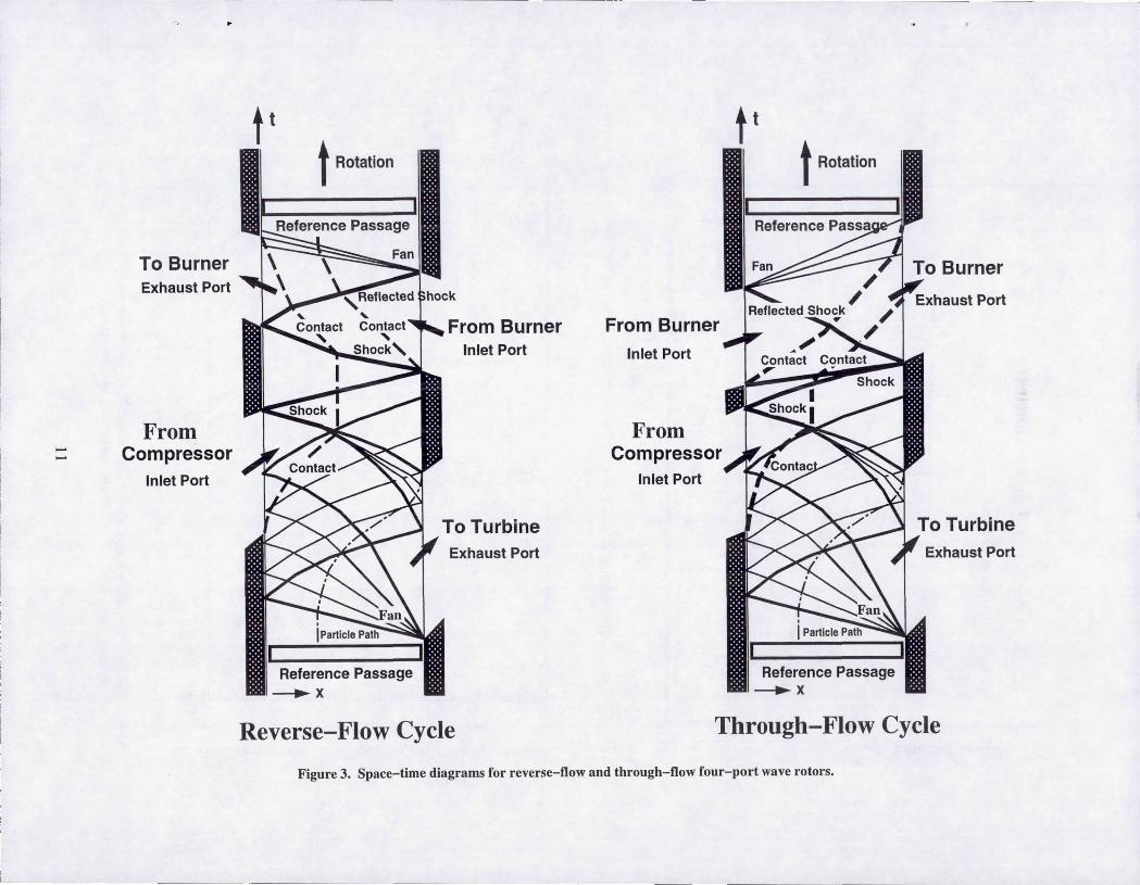
Four-port pressure gain cycle. Figure 3 shows spacetime (x-t) diagrams for "reverse-flow" and "throughflow" four-port pressure wave rotors. The x-t diagram provides a way of representing the time history of the gas dynamic waves in a single wave rotor passage as it moves through the wave rotor cycle. The "bottom, " or compressor port and turbine port part of the wave rotor cycle is identical in the two approaches and, from a engine cycle thermodynamic point-of-view, the two approaches therefore provide identical topping. The "top" parts of the cycles differ: In the reverse-flow cycle, the flow from the burner is used to compress the flow in the rotor passages and only the fresh air is discharged to the burner. Note however that with one cycle per rotor a buffer layer remains in the passages. The buffer layer can be eliminated by immediately following the reverse flow-cycle by its mirror image. This introduces symmetry and in practical applications must be done to assure that both ends of the rotor are washed by the relatively cold compressor discharge air. Attention is restricted to four-port wave rotors using the
..

through-flow approach for the top part of the cycle in the present work. In the through-flow approach, a ponion (30 to 50 %) of once-burned air is recirculated to the burner. The recirculated gas is already burned and conceptually can bypass the burner. In reality, the recirculated gas mixes with the fresh air in the pan to the burner. The fresh, relatively cold, air from the compressor traverses the full length of the rotor in the through-flow approach and, therefore, only one cycle is required to assure cooling throughout the rotor; however, an optimized wave rotor designl9 might well have mUltiple cycles per rotor.
Wave Rotor Perfonnance The wave rotor-topping leads to the higher engine
specific power (SP), i.e., net shaft power (or engine thrust) per mass flow rate, and lower specific fuel consumption (SFC). This is evident from Fig. 4 which shows a total temperature-entropy diagram for the baseline and wave rotor-enhanced engines, each operating with the same turbine inlet temperature and compressor pressure ratio. The heat addition in the zero net power wave rotor-enhanced engine is equal to that of the baseline engine. Less entropy is produced during the heat addition at the higher pressures and temperatures of the wave rotor-enhanced engine and this leads to the higher system efficiency, or lower SFC, or increased specific power for the same heat addition.
The zero net power, pressure gain, wave rotor is a high pressure spool which when coupled with the burner offers significant effective burner pressure gain. A high pressure spool might nominally be characterized by its pressure ratio, and component (compressor and turbine) efficiencies. Alternatively (cf. Refs. 2-4), the high pressure spool can be characterized by specifying the pressure ratio (PTipc) as a function of temperature ratio (TT/Tc). The latter approach is used here to avoid ambiguity in defining wave rotor "component" efficiencies. Fig. 5 provides example performance level ranges for the small, intermediate, and large gas turbine engines calculated in the present work, along with experimentally demonstrated four-pon wave rotor performance levels. 3,4
Figure 5 also provides an "ideal" (dotted curve) wave rotor performance curve in which entropy is produced only by shock waves and non-uniform pon flow mixing. Note that the ideal pressure ratio is that in the rotor frame of reference. The reduction in performance between the ideal and actual wave rotor performance levels is due primarily to viscous, leakage, and inherent partial admission losses and the apparent reduction in
3
pressure ratio between the rotor (relative) and the pon (absolute) frames of reference (cf. Ref. 19). The solid curve in Fig. 5 is a representative locus of performance levels for optimized wave rotors operating on-design (i.e., at the temperature ratio corresponding to engine full-power). It illustrates the qualitative behavior of wave rotor pressure ratio as a function of temperature ratio for optimized wave rotors of an arbitrary class size (e.g., for the large turbofan). The actual magnitude (altitude) of the solid curve corresponding to a given engine class depends on mass flow rate, compressor discharge conditions, and bleed requirements as illustrated by the calculated point design performance levels of the wave rotors of the small, intermediate, and large engines.
According to the example solid curve of Fig. 5, an on-design wave rotor operating with a temperature ratio of 2.0 would attain an effective burner pressure gain (PT/PC) of 1.2. The wave rotor topped engine operating with this temperature ratio would, therefore, have an HPT inlet pressure 20 % higher than its compressor discharge pressure, leading to approximately 20 % increased specific power. An alternate way of interpreting the influence of the wave rotor performance level on engine performance is illustrated in Fig. 6 for a family of constant turbine inlet temperature engine cores: For a fixed turbine inlet temperature (3200 R in Fig. 6), the wave rotor temperature ratio (abscissa) is then set by the particular engine compressor pressure ratio (as shown). Lines of constant SFC can be then drawn as functions of the compressor pressure ratio for the fixed turbine inlet temperature. The solid curve indicates that for a fixed turbine inlet temperature, the wave rotor pressure ratio increases as the compressor pressure ratio decreases. The wave rotor SFC enhancement is made apparent by first choosing a required engine SFC (e.g., 0.32), and then comparing the compressor pressure ratio required for that SFC with wave rotor-topping (= 21: 1), and without topping ( = 49: 1 for a baseline engine with a 5 % burner pressure drop-i.e., p,./pc = 0.95).
Note that any high pressure spool offers the pressure gain described above for the wave rotor and can be characterized similarly; however, a high pressure spool of conventional turbomachinery' cannot withstand the higher burner exhaust temperatures (see Fig. 4) incurred in topping a baseline engine which is already turbine inlet temperature-limited. The burner heat addition in the wave rotor topped engine occurs at pressures 2.5 to 3.5 times higher than in the untopped jet engine so that the engine overall pressure ratio (OPR) is 2.5 to 3.5 times the compressor pressure

ratio. The burner outlet temperature of the topped engine at these pressures is typically 500 to 800 R above the turbine inlet temperature. CFO calculations9,10 predict that the mean wave rotor temperature will be less than, or equal to, the turbine inlet temperature as a result of the intermittent washing by the hot and cold gases. It is this self-cooling feature that suggests that the wave rotor can be operated at realistic mean rotor wall temperatures with peak gas temperatures 500 to 800 R higher than the turbine inlet temperature.
Wave RotorlEngine Study Results Results of a study on the benefits of wave rotor
topping in a small (400 to 600 hp-class) turboshaft engine, an intermediate (3000 to 4000 hp-class) turboshaft engine, and a large (80,000 to 100,000 lbr class) turbofan engine are presented in this section. The engine performance levels, with and without (baseline) wave rotor-enhancement, are calculated using a 1-0 computational model of the wave rotor and a system code to predict engine performance levels.
Wave Rotor Performance Calculations The wave rotor pressure gain is calculated using a
1-0 design/analysis code9 which solves the unsteady viscous flow field in the rotor frame of reference. The 1-D code has been validated using experimental8 and detailed numerical lO results. A single passage is timemarched until the passage flow is periodic in time given constant specified inlet and outlet port boundary conditions. The code can be used to both design the port timing by tracking the gas dynamic waves and also calculate the wave rotor pressure gain and burner loop pressure drop for a specified turbine inlet temperature and compressor exhaust temperature and pressure. The port design accounts for bleed of the highest pressure air from the port going to the burner which is used for HPT first nozzle and first rotor cooling. The performance calculations include losses due to rotor passage gradual opening and closing, viscous and heat transfer effects, and passage-to-casing and passage-toport leakage. The wave rotor is geometrically optimized (cf. Ref. 19) for the engine-specific mass flow rate and local Reynolds numbers which depend on both the compressor discharge conditions and the turbine inlet temperature.
Engine Performance Calculations The NEPp20·21 cycle deck uses scaleable compressor
and turbine maps to calculate on and off-design engine performance. To calculate the enhanced engine performance, the wave rotor is mimicked by replacing the pressure drop of the burner component of the
4
baseline engine with the calculated pressure gain of the wave rotor while keeping heat addition the same. Pressure drops are added upstream and downstream of the wave rotor to simulate the losses in the ducts between the compressor and the wave rotor and between the wave rotor and the HPT. The wave rotorenhanced engine is "redesigned," holding corrected airfl?W into the engine, heat addition (fuel flow), coolmg and bleed flows, and turbine inlet temperature identical to those of the baseline engine at design (Mach 0.0, sea-level). In addition, the net thrusts of the bas~line and enhanced turboshaft engines are the same, whtle the bypass ratios of the turbofan engines are the same (except in the one case noted in Table 2). Therefore, the fan and compressor components of the baseline and enhanced engines are identical. The corrected flow (- mIT / p) to the burner and the high pressure and power turbines of the wave rotor-enhanced engine however are reduced. In the present calculations, the turbine maps are scaled to accommodate the lower corrected flow. In application, the change in corrected flow means either a redesign of the HPT and LPT or, if the wave rotor is added to an existing machine, derivative turbines and compressors of that engine can be mixed to match as closely as possible.
Engine Performance Level Results Table 1 provides a comparison of baseline (untopped)
and wave rotor-enhanced performance levels for example small (400 to 600 hp-class) and intermediate (3000 to 4000 hp-class) turboshaft engines and an example large (80,000 to 100,000 lbrclass) turbofan engine. For a given engine type, the compressor pressure ratio, the turbine inlet temperature, and the engine (core) mass flow rate are fixed. The "unpenalized" results refer to wave rotor-enhanced performance in which no HPT cooling bleed is extracted from the wave rotor; rather, the bleed flow is from the high pressure compressor. The "penalized" results refer to calculations in which required HPT cooling comes from the wave rotor to-burner port. The "penalized" results correspond to an engine in which film cooling of the HPT first nozzle and first rotor is required. This is simulated in the NEPP calculation by extracting bleed from the high pressure compressor discharge to cool the HPT -even though in reality its pressure is too low-and by using a bleed-penalized wave rotor pressure ratio as the burner pressure gain. The cooling bleed percentage is that of the baseline engine. In reality, the temperature of the wave rotor discharge used for cooling is higher than the compressor discharge, commensurate with the wave rotor overall pressure ratio (:= 3: 1); however, the

pressure is higher too so that the increased Reynolds number of the flow works to increase the heat transfer coefficient and thus off-set, to some degree, the decreased cooling capability of the higher temperature wave rotor discharge. Because the specific details of the enhanced engine layout are not defmed at this point, the approach outlined above is used in the present calculations. Further, both results with and without cooling penalty are reported in Table 1, though only the penalized results are discussed below, again, because the details of wave rotor/engine integration are still undefmed enough that it is not clear that cooling will come necessarily from the wave rotor.
The wave rotor-topping enhances the specific power (SP) and specific fuel consumption (SFC) levels of each engine class. The most significant enhancement is found in the small and intermediate turboshaft engines that operate with relatively low compressor pressure ratios. Considering the penalized performance relative to the baseline engine performance, the specific power enhancement of the small and intermediate turboshaft engines is +21 % (i.e., increased by 21 % of baseline SP) and + 19 %, respectively, and the SFC levels are reduced (enhanced) by 17% and 16%, respectively. The wave rotor pressure ratio of the small turboshaft (1.192) is slightly less than that of the intermediate turboshaft (1.201) both due to lower temperature ratio (cf. Fig. 5) and higher viscous losses per mass flow rate (due to small size), in-spite of lower cooling flow requirements. Even so, the small turboshaft engine benefits slightly more from the wave rotor-topping than does the intermediate turboshaft engine. The large turbofan wave rotor performance is severely penalized by 21 % (core flow) cooling bleed. Although the large turbofan runs at a relatively low temperature ratio of 1.905, indicative of its already high compressor pressure ratio, the unpenalized pressure ratio (1.234) is high because of very low viscous losses and low rotational speed of the large, optimized rotor. The penalized wave rotor pressure ratio of 1.133 leads to SFC reduction of 3 % and SP enhancement of 3 %. These modest improvements might suggest discounting wave rotor-topping in the large high bypass turbofans; however, before doing so, the following variations in the approach to exploiting the wave rotor pressure gain in the large engine integration are considered.
Table 2 compares the baseline large turbofan engine with variants of wave rotor-enhanced engines. In all cases the total engine mass flow rate is 2800 lbm/s and the compressor pressure ratio is 38: 1. Variant A is that reported in Table 1 in which the turbine inlet temperature (TiT) and the bypass ratio are fixed at
5
those of the baseline engine, 3200 R and 7.00, respectively. Variant B holds the TiT at 3200 R but increases the bypass ratio to 7.57, thus reducing the core mass flow rate while slightly increasing the bypass mass flow rate, such that the engine thrust is that of the baseline engine (86,727 lbr). Variant C holds the bypass ratio at 7.00 (baseline) but decreases TiT by =::
130 R, again so that the engine thrust is that of the baseline engine. Variants B and C therefore have the same thrust (and specific impulse) of the baseline engine, but each shows a respectable 6.6% reduction in SFC. Variant B is interesting in that the reduced core mass flow rate means the core shrinks in size and weight; this weight reduction can be used to accommodate the weight introduced by the wave rotor and associated dueting. Variant C is interesting in that the TiT has been significantly reduced which has impact on engine life, maintenance, and cost of manufacturing. Considering the already high compressor pressure ratios of current large turbofan engines, the predicted 6 to 7 % enhancement in SFC suggests that wave rotor-topping of the large turbofan engines warrants investigation.
As mentioned, the wave rotor is "self-cooling" in that the average gas path temperature on-board the rotor passage is 500 to 800 R below the burner exhaust temperature, or approximately equal to the absolute temperature into the HPT nozzle. Indeed, detailed CFD calculationslO show that the time-averaged adiabatic rotor wall temperature is close to the static temperature into the HPT nozzle. Therefore, for the small and intermediate turboshaft engines, the mean rotor temperature is expected (according to Table 1) to be :s: 2390 R (or 1930 OF). In the turbofan, however, a mean adiabatic rotor temperature near 3200 R (or 2740 OF) is predicted. The low wave rotor tip speeds suggest much lower stress levels than encountered in current turbomachinery; however, even with robust shrouded passage construction and low tip speeds, the 3200 R mean blade temperature is not tolerable. It is therefore noted that the wave rotor used in the large engine with the 3200 R inlet temperature engine would require additional cooling. Although several cooling schemes are readily envisaged-and although it is noted that ceramic rotors have been built and testedl8-this point is not addressed in the presented work.
Impact on Engine The cycle study calculations presented above indicate
that wave rotor-topping significantly enhances the specific fuel consumption and power (or thrust) per mass flow rate of the turboshaft and turbofan engines. Moving from cycle studies to product, however, raises questions related to the impact of wave rotor/engine

integration on a.) safety; b.) economic factors including direct operating costs, manufacturabiIity, maintainability, and life; c.) off-design performance; d.) system dynamics, e.g., start-up and other anticipated transients; and, for aeropropulsion applications especially, e.) power (thrust) to weight. A detailed analysis of the impact (in the sense of these factors) of the wave rotor integration on the gas turbine engine is beyond the scope of the present work; however, preliminary comments regarding wave rotor integration, manufacturing, weight, and off-design performance are presented below.
Integration Compatibility. The 1-D CFD wave rotor calculations
of the present study show that the component efficiencies of wave rotors are lower than those of modem turbomachinery. This is due in part to viscous losses in the shrouded passages and partial admissionrelated losses. With expected wave rotor on-design effective polytropic compression efficiencies of 82 % to 85 % (estimated) and polytropic expansion efficiencies of 93% to 95% (calculated), it is arguably desirable to use conventional turbo machinery where temperaturelimitations permit; however, the high pressure turbine of modem engines is against an inveterate inlet temperature ceiling. The compressor of many engines is also bounded by discharge temperaturelblade life related constraints. Further, the low corrected flow rates in smaIl engines (and in the final compressor stages of advanced large turbofan engine cores) lead to tolerance-related (e.g., tip leakage induced) inefficiencies. The inherent partial admission of the wave rotor, albeit with certain unavoidable losses, matches well the low corrected flow rates and the shrouded rotor passages eliminate leakage-induced losses, provided that the endwalllrotor clearance gap leakage can be controlled.
Packaging. Although the turbomachinery temperatures have not increased, thermodynamics dictates that the peak (burner) pressures and temperatures of the enhanced engine have increased. Indeed, the burner temperatures and pressures (see Tables 1 and 2) are significantly higher than those of untopped engines. This has an impact on burner size and material temperature and strength requirements. Further, using the results in Ref. 19, optimized pressure gain wave rotors nominally spin with low corrected tip speeds between 250 to 300 ft/s (or tip Mach numbers relative to compressor discharge near 0.25); therefore, off-axis operation is likely in some engines (although on-axis machines have been proposed6). Off-axis operation, and the required
6
transition to and from the compressor and turbine full annuli to the wave rotor ports, necessitates the duct work shown schematically by arrows in Fig. 2c. Packaging the wave rotor in a manner that provides tolerable mechanical and thermal loads and duct pressure losses is critical to engine life, maintenance requirements, and performance. This is not addressed in the present work which attempts only to estimate potential benefit of wave rotor-topping on engine performance.
Manufacturing The straight-bladed, zero net power, pressure gain
wave rotor is arguably easily designed and massproduced 15 at low cost relative to conventional turbomachinery components.
Weight A preliminary estimate of the added weight of the
wave rotor and associated ducting is estimated, using numbers available in Ref. 3, to be approximately 20 % of the baseline engine core weight (also, cf. Ref. 6, p. 13, where the wave rotor is estimated to add 23% of baseline turbofan engine weight). Specific power or thrust on a power/engine weight basis must account for this added weight. The power per engine weight of the small and intermediate turboshaft engines of this study would, by this rough 20% added-weight estimate, remain the same; however, this estimate does not account for the arguable weight reduction resulting from the lower corrected flow to, and subsequent reduction in size of, components (e.g., burner and turbines) and ducting downstream of the wave rotor. Detailed analysis of the wave rotor-enhanced engine weight necessarily depends on the specifics of engine layout and is to be addressed by near-term future work.
Off-Design Operation Figure 7 illustrates the performance of the baseline,
wave rotor-enhanced, and turbomachinery "topped" small turboshaft engine operating between 43 % (compressor pressure ratio = 5.7, TiT = 2020 R) to 100 % full power (compressor pressure ratio = 7.77, TiT = 2390 R): The "topped" engine is a baseline engine with a fictitious high pressure spool comprised of a compressor and turbine unit. The burner pressure drop for the "topped" cycle is the same as that (4.0%) of the baseline engine. The heat addition, inlet temperature (2390 R) into what is now the second turbine, and the compressor discharge conditions are enforced equal to those of the baseline and the wave rotor topped engines at full-power. At the design point (full-power), the high spool compressor and turbine adiabatic (polytropic) efficiencies are set at 0.85 (0.86)
\.

and 0.90 (0.896), respectively, and the high spool compressor pressure ratio is 1.75. This sets the pressure gain of the high pressure spool equal to that of the unpenalized wave. rotor (1.22) at the full-power design point. The engine overall pressure ratio is 13.6 and the burner inlet and outlet temperatures are 1288 R and 2653 R, respectively. The fictitious "topped" scenario increases the high spool turbine inlet temperature to 2653 R. These numbers can be compared with those of the baseline and wave rotorenhanced engines shown in Table 1.
In Fig. 7, SFC is plotted against shaft horsepower for the baseline, wave rotor-enhanced engine, and turbomachinery "topped" engines. The off-design performance of the baseline and "topped" systems are calculated within NEPP using standard compressor and turbine maps scaled to reproduce the full-power (design) performance. The off-design wave rotor pressure ratio (also not penalized for bleed flow here) is calculated using the 1-D design/analysis code, and depends on wave rotor speed and engine heat addition. In the results shown in Fig. 7, the wave rotor runs with constant 17,000 rpm throughout the 43% to 100% power range. Figure 7 shows that the three engines perform off-design in qualitatively the same manner, and that the performance of the "topped" engine and the wave rotor-enhanced engine is indistinguishable over the part-power range. Clearly the off-design behavior of wave rotor-enhanced and baseline turboshaft engines is the same.
Summary Calculated performance levels of small (400 to 600
hp-class) and intermediate (3000 to 4000 hp-class) wave rotor-enhanced turboshaft engines show 19% to 21 % increase in specific power (SP) and 16% to 17% decrease in specific fuel consumption (SFC) over the baseline engines. Calculations of wave rotor-enhanced large (80,000 to 100,000 lbrclass) turbofan engine, equal in thrust to the baseline engine, shows a 6 % to 7 % reduction in SFC along with the attractive feature of significantly (= 130 R) reducing the high pressure turbine inlet temperature. The wave rotor-enhanced engine behaves off-design (43% to 100% full-power) like a conventional engine. The additional weight of the wave rotor and associated ductwork is expected to be less than twenty-percent of the baseline engine core weight. Discussion concerning the impact of integrating the four-port wave rotor points to tenable technical challenges regarding packaging, added ductwork with associated pressure losses, mechanical and thermal loads, and maintenance.
7
References IMeyer, A., "Recent Developments in Gas Turbines,"
Mech. Engineering, 69, 1947, pp. 273-277. 2Goldstein, A. W., Klapproth, J. F., and Hartmann, M. J.,
"Ideal Performance of Valved-Combustors and Applicability to Several Engine Types," ASME-57-A-I02, 1957.
3Mathur, A., "A Brief Review of G.E. Wave Engine Program (1958-1963)," eds. Shreeve, R. P. and Mathur, A., Proc. of the 1985 ONRINAVAlR Wave Rotor Research and Technology Workshop, Report NPS-67-85-008, Naval Postgraduate School, Monterey, CA, May, 1985, pp. 171-193.
4Moritz, R., "Rolls~Royce Study of Wave Rotors 1965-1970," ibid., pp. 116-124.
sWeatherston, R. C. and Hertzberg, A., "The Energy Exchanger, a New Concept for High-Efficiency Gas-Turbine Cycles," J. Engineeringfor Power, April, 1967, pp. 218-228.
&faussig, R. T., "Wave Rotor Turbofan Engines for Aircraft," ed. Sladky, J. F., Jr., Machinery for Direct FluidFluid Energy Exchange, AD-07, The American Society of Mechanical Engineers, N.Y., Dec., 1984, pp. 9-45.
7Zauner, E., Chyou, Y.-P., Walraven, F., and Althaus, R., "Gas Turbine Topping Stage Based on Energy Exchangers: Process and Performance," ASME-93-GT-58, May, 1993.
8Wilson, J. and Fronek, D., "Initial Results from the NASA Lewis Wave Rotor Experiment," AIAA-93-2521, June, 1993; also NASA-TM-I06148.
!/Paxson, D. E., "A Comparison Between Numerically Modelled and Experimentally Measured Loss Mechanisms in Wave Rotors," AIAA-93-2522, June, 1993; also NASA-TM-106279.
IOWelch, G. E., "Two-Dimensional Numerical Study of Wave Rotor Flow Dynamics," AIAA-93-2525, June, 1993.
\1Larosiliere, L. M., "Three-Dimensional Numerical Simulation of Gradual Opening in a Wave Rotor Passage," AIAA-93-2526, June, 1993.
12Wilson, J. and Paxson, D. E., "Jet Engine Performance Enhancement Through Use of a Wave-Rotor Topping Cycle, " NASA-TM-4486, October, 1993.
13 Azoury, P. H., "An Introduction to the Dynamic Pressure Exchanger," Proc. Inst. Mech. Eng., 180, Pt. 1, 1965-1966, pp. 451-480.
14Kentfield, J. A. C., "The Performance of PressureExchanger Dividers and Equalizers," J. Basic Engineering, Sept. 1969, pp. 361-370.
ISBerchtold, M., "Supercharging with Comprex," eds. Shreeve, R. P. and Mathur, A., Proc. of the 1985 ONRINAVAlR Wave Rotor Research and Technology Workshop, Report NPS-67-85-OO8, Naval Postgraduate School, Monterey, CA, May, 1985, pp. 51-74.
16Nalim, M. R., "Preliminary Assessment of Combustion Modes for Internal Combustion Wave Rotors," AIAA-95-2801, July, 1995.
17Pearson, R. D., "Performance Predictions for Gas Wave Turbines Including Practical Cycles with Wide Speed Range, " eds. Shreeve, R. P. and Mathur, A., Proc. of the 1985 ONRINAVAIR Wave Rotor Research and Technology Workshop, Report NPS-67-85-008, Naval Postgraduate School, Monterey, CA, May, 1985, pp. 329-378.

ISZehnder, G., Mayer, A., and Matthews, L., "The Free Running Comprex," SAE-890452, Feb.-Mar., 1989. l~iIson, J. and Paxson, D. E., "Optimization of Wave
Rotors for Use as Gas Turbine Engine Topping Cycles," SAE-951411, May, 1995.
2Oplencner, R. and Snyder, C., "The NavylNASA Engine Program (NNEP89) - A User's Manual, " NASA-TM-I05186, 1991.
2lKlann, J. and Snyder, C., "NEPP Programmer's Manual (NASA Engine Performance Program), Vols. I and II," NASA-TM-I06575, 1994.
Table 1. Baseline and wave rotor-enhanced engine performance levels for small and intermediate turboshaft engines and large high bypass ratio turbofan. For a given engine type, shaft pressure ratio, turbine inlet temperature, and engine mass flow rate are fixed. "Penalized" denotes cases where wave rotor supplies HPf cooling flow.
Small Intermediate Large Parameter Turboshaft Turboshaft Turbofan*
Shaft Pressure Ratio
Turbine inlet Temperature (R)
Mass Flow Obm/s)
Bleed-Percent!
Baseline SFCZ Unpenalized SFC
Penalized SFC
Untopped Power1 Unpenalized Power
Penalized Power
Untopped S.P.4
Unpenalized S.P. Penalized S.P.
WR Temp. Ratios
Burner Pressure Ratio6
WR Pressure Ratio' Penalized WR Pres. Ratio
Burner Exhaust Temp. (R) Unpenalized Exhaust Temp Penalized Exhaust Temp.
Baseline OPRs
Unpenalized OPR Penalized OPR
*Bypass ratio = 7.00. Total flow is 2800 Ib.,ls and core flow is 350 Ib .. /s. 'Percent of compressor discharge flow used for cooling. lSpecific fuel consumption(lb .. lhr-hp). 'Net Power (\Ip) for turboshafts and thrust (Ib,) for turbofan. ·Power/mass flow rate (hp/lb.,ls) for wrboshaftsand specific impulse (Ibtllbm/s) for turbofan. 'Defined as ratio of total temperatures in wave rotor turbine exhaust and compressor inlet ports.
7.77 7.89 38.1
2390 2376 3200
5.03 26.2 2800
4.9 11.4 2l.0
0.622 0.538 0.313 0.502 0.430 0.300 0.512 0.452 0.304
575.8 3342 86,727 712.9 4178 90,655 698.7 3979 89,393
114.5 127.5 30.97 141.7 159.4 32.38 138.9 151.8 31.93
2.209 2.340 1.906
0.96 0.96 0.95 1.220 1.283 1.234 1.192 1.201 1.133
2390 2376 3200 2972 2936 3939 2983 2969 3998
7.77 7.89 38.1 25.6 26.7 123 25.1 25.5 116
'Defined as ratio total pressure into HPT and total pressure of compressor discharge.
8
'Defined as ratio of total pressures in wave rotor exhaust to turbine and compressor discharge (effective burner pressure gain). "Defined as ratio burner inlet pressurelcompressorinlet pressure.
..
Table 2. Large turbofan wave rotor-enhanced engine variants with fixed compressor pressure ratio of 38:1, total mass flow rate of 2800 Ibm/s, coolant bleed of 21 % of core flow, and wave rotor pressure ratio of 1.13 (cooling-penalized value).
I Turbofan Variant: t II Baseline I A I B I C
Bypass Ratio 7.00 7.00 7.57 7.00
Turbine Inlet Temperature (R) 3200 3200 3200 3068t
SFC Obmlhr-hp) 0.313 0.304 0.292 0.292
Thrust Obr) 86,727 89,393 86,727 86,732
S.P. Obr'lbm/s) 30.97 31.93 30.97 30.98
Burner Exhaust Temp. (R) 3200 3998 3998 = 3833
Overall Pressure Ratio (OPR) 38.1 116 116 = 116
'Variants: A Wave rotor-enhanced engine with baseline engine turbine inlet temperature and bypass ratio . B Wave rotor-enhanced engine with baseline engine turbine inlet temperature but increased bypass ratio such that thrust is same as
baseline engine thrust. C Wave rotor-enhanced engine with baseline engine bypass ratio with reduced turbine inlet temperature such that thrust is same as
basel ine engine thrust.
'Reducing the turbine inlet temperature, at a given compressor pressure ratio, reduces the wave rotor temperature ratio, which might suggest a reduction in wave rotor pressure ratio (considering Fig. 5); however, here, the reduction in turbine inlet temperature also leads to a reduction in bleed penalty to wave rotor which is expected to at least offset this expected pressure ratio reduction.
From Burner
From ~ Compressor
To
Turbine
Figure 1. Four-port wave rotor schematic diagram.
9
I
-o
Wave Rotor
Fuel
Figure 2a. Pressure gain wave rotor with combustion on the rotor.
Figure 2c. Pressure gain wave rotor with
conventional burner.
Fuel
Wave Rotor
Figure 2b. Wave engine with combustion on the rotor.
Compressor
Figure 2d. Wave engine with conventional burner.
Figure 2. Wave rotor/gas turbine engine integration variants.
......
......
To Burner Exhaust Port
From Compressor
Inlet Port
--------
tt t Rotation
Reference Passage --.x
From Burner Inlet Port
To Turbine Exhaust Port
Reverse-Flow Cycle
tt t Rotation
From Burner Inlet Port
From Compressor ~rcomacY'"
Inlet Port
Reference Passage ~x
To Burner
To Turbine Exhaust Port
Through-Flow Cycle
Figure 3. Space-time diagrams for reverse-flow and through-flow four-port wave rotors.

•••••
Wave Rotor-Enhanced Engine
Baseline Engine P T} Pressure
P Gain T Effecti·;~·· t······················
........................•..•... ~:;;;;~~ .. ~ ..... . Turbine Inlet Temperature
• • •
Baseline Cycle
• • • • •
Etili~;:~;;i ·1' Power T Output
Entropy
Figure 4. Temperature-entropy diagram showing thermodynamic benefit of wave rotor topping cycle.
~
o !I) !I)
~ a. E o ~ ~ ::J !I) !I)
~ 0..
1.3
1.2
~ 1.1
Four-Port Ideal Performance .', .. '
.' Large Turbofan Unpenalized -Performance
1.75 2.00 2.25
"
Example On-Design Four-Port Performance with Losses
__ -0
_ - - G.E, Performance Data (1959-1963)3
2.50 2.75
Turbine Inlet Temperature/Compressor Discharge Temperature
3.00
Figure S. Wave rotor performance map (PT/Pc versus TTffJ showing NASA LeRC predicted performance and G.E.3 and RoUs-Royce4 performance data.
12
--- .-- '- ------------
I
I

,- ----- - -- ---
(I) 1.4 ... ::s III III (I) Specific Fuel Consumption (Ibmlhr-hp) = 0,31 0.32 0.34 0.36 ...
a.. (I)
Example On-Design Four-Port / 01 ... 1.3 C'Cl Wave Rotor Performance Curve / / .c 0
- - - Constant SFC Lines / I / III
/ (5 / / ... 0.30 / / 0 / III / / III 1.2 / / / /
~ c.. / / / / E / I / / / 0 / ~ ;: / / / ~ / / / / ::s / / III 1.1 / / / III ./ / ~ ./ / / / /
a.. ./ / / / / ]! / / / / Shaft c / / / / .-- Pressure Ratio Q) 1.0 ./ /
30:1/~5: 1 }6:1 at TiT = 3200 R
c 55:1 4!<Y.1 15:1 12:1 10:1 :a ... / ::s I-
1.50 1.75 2.00 2.25 2.50 2.75 3.00
Turbine Inlet Temperature/Compressor Discharge Temperature
Figure 6. Lines of constant specific fuel consumption for family of engine cores with 3200 R turbine inlet temperature.
c o 0.7 a. E ::s III c o () 0.6 Q) ::s
LL o
;;:
.~ 0.5 c.
00
---Baseline Engine - - - Wave Rotor-Enhanced Engine ..... ... ... Turbomachinery-Topped Engine
0.4~~~~~~~~~~~~~~~~~~~~~~J-~
200 300 400 500 600 700 800
Shaft Horsepower (hp)
Figure 7. Off-design performance of baseline, wave rotor-enhanced, and turbomachinery-topped engines.
13

[
I I I r
REPORT DOCUMENTATION PAGE Form Approved
OMB No. 0704-0188 Public reponing burden for this collection of information is estimated to average 1 hour per response. including the time for r9lliewing instructions. searching existing data sources. gathering and maintaining the data needed. and colll>leting and reviewing the collection of InfOrmalion. Send comments regarding this burden estimate or any other aspect of this collection of information. including suggestions for reducing this burden. to Washington HeadQuaners Services. Directorate for Information Operations and Reports. 1215 Jefferson Davis Highway. Suite 1204. Arlington. VA 22202·4302. and to the Office of Management and Budget. Paperworll Reduction Project (0704-0188). Washington. DC 20503.
,. AGENCY USE ONLY (Leave blank) J 2. REPORT DATE .13_ REPORT TYPE AND DATES COVERED
June 1995 Technical Memorandum 4. TITLE AND SUBTITLE 5_ FUNDING NUMBERS
Wave Rotor-Enhanced Gas Turbine Engines
WU-505-90-58 6. AUTHOR(S)
Gerard E. Welch, Scott M. Jones, and Daniel E. Paxson
7. PERFORMING ORGANIZATION NAME(S) AND ADDRESS(ES) 8. PERFORMING ORGANIZATION NASA Lewis Research Center REPORT NUMBER
OeveIand, Ohio 44135-3191 and
E-9777 Vehicle Propulsion Directorate U.S. Anny Research Labor.at01Y OeveIand, Ohio 44135-3191
9. SPONSORING/MONITORING AGENCY NAME(S) AND ADDRESS(ES) 10. SPONSORING/MONITORING
National Aeronautics and Space Administration AGENCY REPORT NUMBER
Washington, D.C. 20546-0001 NASA TM-I06998 and
ARL-TR-806 U.S. Army Research Laboratory Adelphi, Maryland 20783-1145 AIAA-95-2799
11. SUPPLEMENTARY NOTES
Prepared for the 31st Joint Propulsion Conference and Exhibit cosponsored by AIAA, ASME, SAE, and ASEE, San Diego, California, July 10-12, 1995. Gerard E. Welch, Vehicle Propulsion Directorate, U.S. Army Research Laboratory, NASA Lewis Research Center; Scott M. Jones and Daniel E. Paxson, NASA Lewis Research Center. Responsible person, Gerard E. Welch, organization code 2760, (216) 433-8003.
'2a. DISTRIBUTIONIAVAILABIUTY STATEMENT 12b. DISTRIBUTION CODe
Unclassified -Unlimited Subject Category 07
This publication is available from the NASA Center for Aerospace Information, (301) 621-{)390.
13. ABSTRACT (Maximum 200 words)
The benefits of wave rotor-topping in small (400 to 600 hp-class) and intennediate (3000 to 4000 hp-class) turboshaft engines, and large (80,000 to 100,000 lbrclass) high bypass ratio turbofan engines are evaluated. Wave rotor perfonnance levels are calculated using a one-dimensional design/analysis code. Baseline and wave rotor-enhanced engine perfonnance levels are obtained from a cycle deck in which the wave rotor is represented as a burner with pressure gain. Wave rotor-topping is shown to significantly enhance the specific fuel consumption and specific power of small and intermediate size turboshaft engines. The specific fuel consumption of the wave rotor-enhanced large turbofan engine can be reduced while operating at Significantly reduced turbine inlet temperature. The wave rotor-enhanced engine is shown to behave off-design like a conventional engine. Discussion concerning the impact of the wave rotor/gas turbine engine integration identifies tenable technical challenges.
14. SUBJECT TERMS '5. NUMBER OF PAGES
15 Wa¥(; rotor; Gas turbine engines; Turboshaft engine; Turbofan engine '6. PRICE CODE
A03 17. SECURITY CLASSIFICATION 18. SECURITY CLASSIFICATION 19. SECURITY CLASSIFICATION 20. LIMITATION OF ABSTRACT
OF REPORT OF THIS PAGE
Unclassified Unclassified
NSN 7540-01 -280-5500
OF ABSTRACT
Unclassified
Standard Form 298 (Rev. 2-89) Prescribed by ANSI Std. 239-'8 298-'02
___ 1

National Aeronautics and Space Administration
Lewis Research Center 21000 Brookpark Rd. Cleveland,OH 44135-3191
Official Business Penalty for Private Use $300
POSTMASTER: If Undeliverable - Do Not Return
l __ , ______ ~~_~~~~~~ __ _