ways of eliminating the road effect in transition zones
TRANSCRIPT
TRANSPORT Ways of Eliminating the Road Effect in Transition …
85
1. PROBLEM FORMULATION
Sections of the railway track in the contact area
with the engineering object require special
attention, as they are most often exposed to vertical
deformations that result in damage to the surface.
The reason for this undesirable phenomenon is the
sudden change in track support stiffness (Fig. 1),
leading to the difference between the nature of the
track base work on the railway route and the track
operation at the engineering facility. The jumping
variability of track rigidity (called the threshold
effect) is an important factor in increasing dynamic
impacts and uneven track subsidence in the
operation process and, as a result, increasing
distortions in the "quiet" riding.
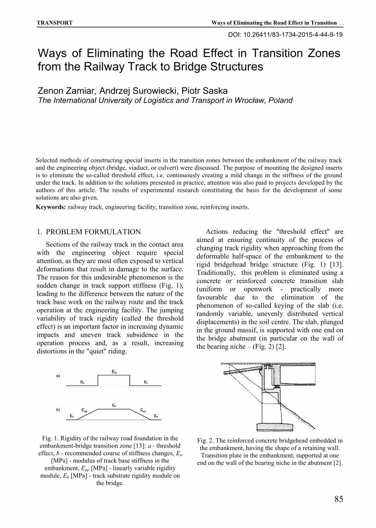
Fig. 1. Rigidity of the railway road foundation in the
embankment-bridge transition zone [13]: a - threshold
effect, b - recommended course of stiffness changes, En
[MPa] - modulus of track base stiffness in the
embankment, Enp [MPa] - linearly variable rigidity
module, E0 [MPa] - track substrate rigidity module on
the bridge.
Actions reducing the "threshold effect" are
aimed at ensuring continuity of the process of
changing track rigidity when approaching from the
deformable half-space of the embankment to the
rigid bridgehead bridge structure (Fig. 1) [13].
Traditionally, this problem is eliminated using a
concrete or reinforced concrete transition slab
(uniform or openwork - practically more
favourable due to the elimination of the
phenomenon of so-called keying of the slab (i.e.
randomly variable, unevenly distributed vertical
displacements) in the soil centre. The slab, plunged
in the ground massif, is supported with one end on
the bridge abutment (in particular on the wall of
the bearing niche – (Fig. 2) [2].
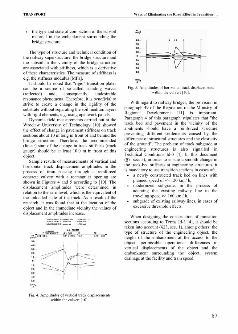
Fig. 2. The reinforced concrete bridgehead embedded in
the embankment, having the shape of a retaining wall.
Transition plate in the embankment, supported at one
end on the wall of the bearing niche in the abutment [2].
Ways of Eliminating the Road Effect in Transition Zones from the Railway Track to Bridge Structures
Zenon Zamiar, Andrzej Surowiecki, Piotr Saska The International University of Logistics and Transport in Wrocław, Poland
Selected methods of constructing special inserts in the transition zones between the embankment of the railway track
and the engineering object (bridge, viaduct, or culvert) were discussed. The purpose of mounting the designed inserts
is to eliminate the so-called threshold effect, i.e. continuously creating a mild change in the stiffness of the ground
under the track. In addition to the solutions presented in practice, attention was also paid to projects developed by the
authors of this article. The results of experimental research constituting the basis for the development of some
solutions are also given.
Keywords: railway track, engineering facility, transition zone, reinforcing inserts.
DOI: 10.26411/83-1734-2015-4-44-9-19

Ways of Eliminating the Road Effect in Transition … Logistics and Transport No 4(44)/2019
86
The length of this plate depends, among others,
on the expected amount of settlement of the
embankment ground and traffic. The end of the
plate should reach beyond the wedge of the
fragment, so its length also depends on the height
of the embankment [2]. The theoretical length of
the slab can be determined on the basis of the
classical method of calculating the soil pressure,
developed by Ch. Coulomb [3]. Assumptions for
the solution of Ch. Coulomb is given in Fig. 3 [3].
The force polygon Ec, Q, G shows that the
pressure of the soil massif on the retaining wall
(bridge abutment) is expressed by the relationship:
Ec = G tg (θ – φ’) (1)
in which:
G - weight of the fracture wedge (OAB triangle),
φ ’- angle of internal friction of the soil massif.
The weight of the fragment wedge is:
G = 0,5 γ h2 ctg θ (2)
Thus, the total pressure of the soil massif is
determined as follows:
Ec = 0.5 γ h2 ctg θ tg (θ - φ ’) (3)
The extreme pressure condition requires the
calculation of the first derivative of Ec after the
value of the angle of inclination of the slip line θ to
the level and equating this derivative to zero [3]:
dEc/dθ = 0,5 γ h2 {– tg (θ – φ’) (sin2 θ)
-1 +
+ ctg θ [cos2 (θ – φ’)]
-1} = 0 (4)
After solving the last equation, we get:
θ = 0,25 π + 0,5 φ’ (5)
Finally, the fragment wedge length,
characterized by the OA segment is:
OA = h tg (0,5 π – θ) (6)
The OA parameter defines the minimum length
of the transition plate according to [2].
Fig. 3. Assumptions for the solution of Ch. Coulomb,
concerning the determination of soil pressure on a
retaining wall (in the present case the retaining wall is a
bridge abutment) [3]. Marking: BA - slip line
determined from the extreme pressure condition, OA -
fragment wedge length, h - embankment height (height
of bridge abutment).
As reported by F. Leonhardt [8], the slope of
the plate 1: n (away from the bridge) should not
usually exceed 1: 200, and in the case of high
category communication routes 1: 300, so the
settlement of the " sn " embankment, which is e.g.
sn = 0.05 m would require a board with a length of
L = 10 ÷ 15 m. In the manual [2] the following
information is provided regarding transition plates:
the slope of the slab should be greater, the
more susceptible the surface of the traffic
route (in this case the railway track) at the
access to the bridge,
the use of a transition plate is expedient
especially in cantilever bridges or with
abutments embedded in the embankment (Fig.
2).
According to J. Szczygieł [15], the length of
transition plates should be at least 2.5 ÷ 3.0 m in
average conditions, while at high embankments on
railway lines up to 10.0 m.
The intensity of this "threshold effect" depends
on many factors, including from:
type of structure and size of the engineering
structure (steel, composite, concrete structure,
reinforced concrete, etc.; small, single or
multi-span bridge, culvert),
type of pavement on the bridge (e.g. railroad
bed on ballast, bridge cranes or direct
attachment of rails to the bridge structure),
technical condition of the pavement on the
bridge (characterized e.g. by geometric
irregularities),
the type and technical condition of the
pavement structure in the vicinity of the
bridge structure,
the type and technical condition of vehicles
and their speed and driving style (e.g. braking,
acceleration),
TRANSPORT Ways of Eliminating the Road Effect in Transition …
87
the type and state of compaction of the subsoil
material in the embankment surrounding the
bridge structure.
The type of structure and technical condition of
the railway superstructure, the bridge structure and
the subsoil in the vicinity of the bridge structure
are associated with stiffness, which is a derivative
of these characteristics. The measure of stiffness is
e.g. the stiffness modulus [MPa].
It should be noted that "rigid" transition plates
can be a source of so-called standing waves
(reflected) and, consequently, undesirable
resonance phenomena. Therefore, it is beneficial to
strive to create a change in the rigidity of the
substrate without separating the soil medium layers
with rigid elements, e.g. using openwork panels.
Dynamic field measurements carried out at the
Wrocław University of Technology [10] showed
the effect of change in pavement stiffness on track
sections about 10 m long in front of and behind the
bridge structure. Therefore, the recommended
(linear) start of the change in track stiffness (track
gauge) should be at least 10.0 m in front of this
object.
Sample results of measurements of vertical and
horizontal track displacement amplitudes in the
process of train passing through a reinforced
concrete culvert with a rectangular opening are
shown in Figures 4 and 5 according to [10]. The
displacement amplitudes were determined in
relation to the zero level, which is the equivalent of
the unloaded state of the track. As a result of the
research, it was found that at the location of the
object and in the immediate vicinity the values of
displacement amplitudes increase.
Fig. 4. Amplitudes of vertical track displacements
within the culvert [10].
Fig. 5. Amplitudes of horizontal track displacements
within the culvert [10].
With regard to railway bridges, the provision in
paragraph 49 of the Regulation of the Ministry of
Regional Development [11] is important.
Paragraph 4 of this paragraph stipulates that "the
track bed and pavement in the vicinity of the
abutments should have a reinforced structure
preventing different settlements caused by the
difference of structural structures and the elasticity
of the ground". The problem of track subgrade at
engineering structures is also signalled in
Technical Conditions Id-3 [4]. In this document
(§7, sec. 5), in order to ensure a smooth change in
the track-bed stiffness at engineering structures, it
is mandatory to use transition sections in cases of:
a newly constructed track bed on lines with
planned speed of v> 120 km / h,
modernized subgrade, in the process of
adapting the existing railway line to the
traveling speed v> 160 km / h,
subgrade of existing railway lines, in cases of
excessive threshold effects.
When designing the construction of transition
sections according to Terms Id-3 [4], it should be
taken into account (§23, sec. 1), among others: the
type of structure of the engineering object, the
height of the embankment at the access to the
object, permissible operational differences in
vertical displacements of the object and the
embankment surrounding the object, system
drainage at the facility and train speed.
Ways of Eliminating the Road Effect in Transition … Logistics and Transport No 4(44)/2019
88
2. SOME SOLUTIONS OF TRANSITION
SECTIONS USED ON RAILWAY LINES
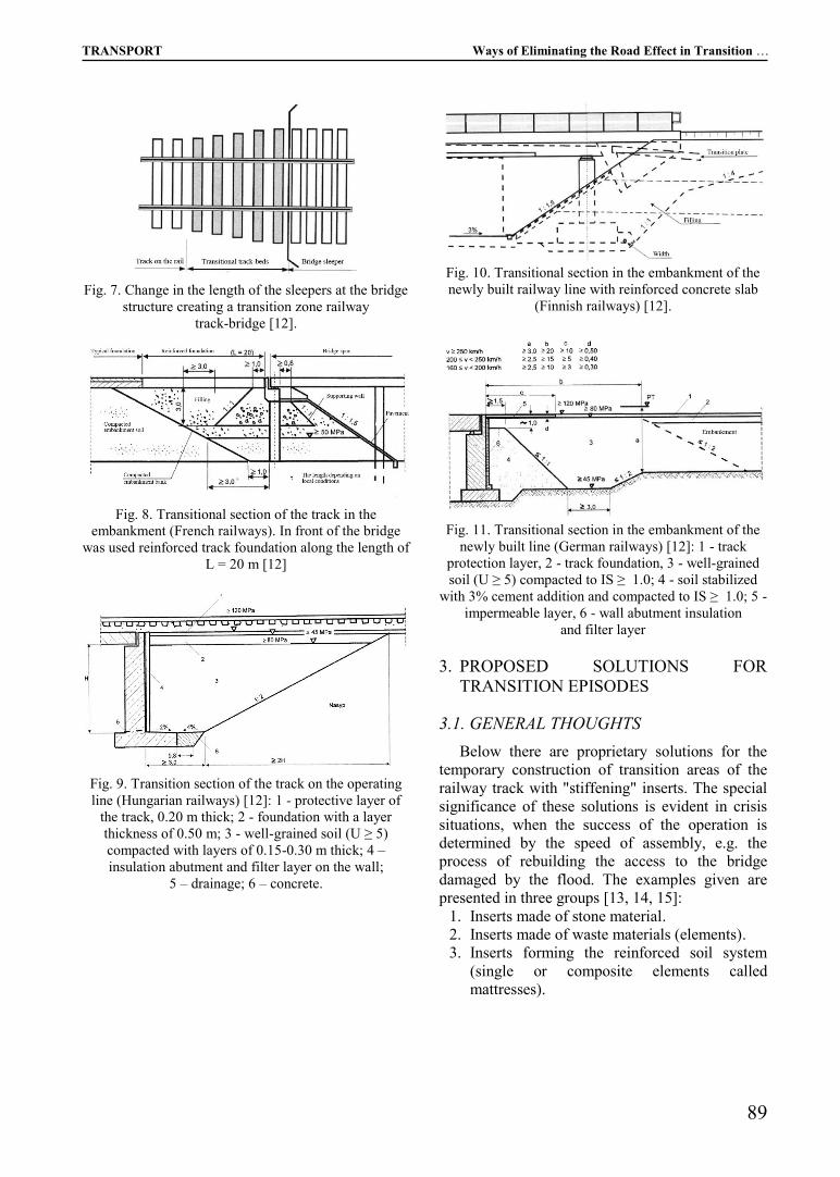
According to [17, 18], one of the solutions is
laying under the pavement structure on the final
sections of the bridge structure (at least 3.5 m long)
mats of hardened foam, in order to adapt the
rigidity of the pavement to the rigidity of the
bridge structure. Behind the abutment, soil is
stabilized with cement mortar (Fig. 6a, 6b). In
these solutions (Fig. 6) there is a wedge of
stabilized soil, the dimensions of which depend on
the type and load capacity of the subsoil and
should be determined depending on the difference
between the vertical stiffness of the object and the
subgrade.
Fig. 6. Diagrams of transition track sections, laid
between the bridge and the pavement on the railway
route [17, 18]: a) 1 - earth embankment stabilized with
cement mortar, 2 - drainage line, 3 - earth embankment;
b) 1 - bridge structure, 2 - elastic layer, 3 - concrete slab
or a layer of soil stabilized with cement, 4 - ballastless
track surface, c) 3 - concrete slab or soil stabilized with
cement layer, 4 - ballastless track surface, 5 - pavement
with ballast layer, 6 - ballast pavement on the bridge
structure.
In contrast, Annex 16 (Information) to
Conditions Id-3 [4] gives examples of the
construction of transitional sections of the track at
engineering facilities, concerning cases of: the
operating railway line, the newly built line for the
speed of v <160 km / h, and the newly built for v >
160 km / h. The possibility of increasing the
effectiveness of these constructions is provided for
by installing additional anti-vibration mats on
bridge structures.
In practice, on the transitional sections of the
lines in use, due to the limited possibilities to
change the structure of the subgrade, the most
commonly used is stiffening of the pavement and
strengthening of the upper layers of the subgrade
[12]. Pavement stiffeners consist, for example, in:
elongation of fenders existing on the bridge
structure, installation of elongated sleepers at the
bridge structure with track on the bridge cranes.
Strengthening the upper layers of the track-bed
is carried out using:
track protective layers in one- or many-layer
system,
transition plates reducing operational load,
transferred to the subgrade ground,
stone columns (these columns are holes with a
diameter of about 0.30 m and a depth of about
2.0 m, filled with maximally compacted
aggregate; the task of the columns is to
strengthen weak soil of the track bed and
improve drainage of the track bed).
Exemplary constructions of transition sections
are illustrated in Figures 7, 8, 9, 10 and 11
according to [12].
In the manual [12] important guidelines for
designing the track base at engineering objects are
given. Here are some:
track-bed materials embedded in transition
sections should be easily compacted and be
useful for cement improvement,
due to track deflection (vertical displacement),
it is expedient to use the same pavement on
the bridge structure and outside it,
track maintenance works (e.g. ballast
cleaning, track positioning) that are carried
out on railway routes should also be carried
out along the length of the transition sections.-
track-bed materials embedded in transition
sections should be easily compacted and be
useful for cement improvement,
due to track deflection (vertical displacement),
it is expedient to use the same pavement on
the bridge structure and outside it,
track maintenance works (e.g. ballast
cleaning, track positioning) that are carried
out on railway routes should also be carried
out along the length of the transition sections.
TRANSPORT Ways of Eliminating the Road Effect in Transition …
89
Fig. 7. Change in the length of the sleepers at the bridge
structure creating a transition zone railway
track-bridge [12].
Fig. 8. Transitional section of the track in the
embankment (French railways). In front of the bridge
was used reinforced track foundation along the length of
L = 20 m [12]
Fig. 9. Transition section of the track on the operating
line (Hungarian railways) [12]: 1 - protective layer of
the track, 0.20 m thick; 2 - foundation with a layer
thickness of 0.50 m; 3 - well-grained soil (U ≥ 5)
compacted with layers of 0.15-0.30 m thick; 4 –
insulation abutment and filter layer on the wall;
5 – drainage; 6 – concrete.
Fig. 10. Transitional section in the embankment of the
newly built railway line with reinforced concrete slab
(Finnish railways) [12].
Fig. 11. Transitional section in the embankment of the
newly built line (German railways) [12]: 1 - track
protection layer, 2 - track foundation, 3 - well-grained
soil (U ≥ 5) compacted to IS ≥ 1.0; 4 - soil stabilized
with 3% cement addition and compacted to IS ≥ 1.0; 5 -
impermeable layer, 6 - wall abutment insulation
and filter layer
3. PROPOSED SOLUTIONS FOR
TRANSITION EPISODES
3.1. GENERAL THOUGHTS
Below there are proprietary solutions for the
temporary construction of transition areas of the
railway track with "stiffening" inserts. The special
significance of these solutions is evident in crisis
situations, when the success of the operation is
determined by the speed of assembly, e.g. the
process of rebuilding the access to the bridge
damaged by the flood. The examples given are
presented in three groups [13, 14, 15]:
1. Inserts made of stone material.
2. Inserts made of waste materials (elements).
3. Inserts forming the reinforced soil system
(single or composite elements called
mattresses).
Ways of Eliminating the Road Effect in Transition … Logistics and Transport No 4(44)/2019
90
3.2. STIFFENING INSERT AS A LAYER OF
STONE MATERIAL
Fig. 12 illustrates a longitudinal view of an
insert partially stiffening a railway pavement,
constructed of stone aggregate as a macadam
structure (aggregate layers of the same fraction)
and located directly under the track ballast.
The insert has a variable thickness and consists
of the following elements:
at a length of 10 m adjacent to the bridgehead,
made of broken stone with a thickness of 0.60
m and from the top it is "closed" with a layer
of 0.15 m thick,
directly at the abutment, the thickness of this
layer is increased to 1.60 m,
the second (extreme) section with a length of
10.0 m is a clinker layer with a thickness of
0.15 m.
Fig. 12. Longitudinal section through a stiffening layer
in the transition zone of a railway track - bridge
structure made of stone material [13]: 1 - ballast, 2 -
wedge 0.15 m (closing layer), 3 - broken stone pitch
0.60 m, 4 - embankment ground (subgrade)
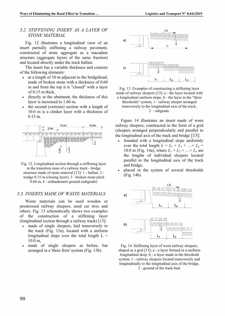
3.3. INSERTS MADE OF WASTE MATERIALS
Waste materials can be used wooden or
prestressed railway sleepers, used car tires and
others. Fig. 13 schematically shows two examples
of the construction of a stiffening layer
(longitudinal section through a railway track) [13]:
made of single sleepers, laid transversely to
the track (Fig. 13a), located with a uniform
longitudinal slope over the total length L =
10.0 m,
made of single sleepers as before, but
arranged in a 'three frets' system (Fig. 13b).
Fig. 13. Examples of constructing a stiffening layer
made of railway sleepers [13]: a - the layer located with
a longitudinal uniform slope, b - the layer in the "three
thresholds" system, 1 - railway sleeper arranged
transversely to the longitudinal axis of the track,
2 – subgrade.
Figure 14 illustrates an insert made of worn
railway sleepers, constructed in the form of a grid
(sleepers arranged perpendicularly and parallel to
the longitudinal axis of the track and bridge [13]: founded with a longitudinal slope uniformly
over the total length L = L1 + L2 + …+ Ln =
10.0 m (Fig. 14a), where L1 + L2 + …+ Ln are
the lengths of individual sleepers located
parallel to the longitudinal axis of the track
and bridge,
placed in the system of several thresholds
(Fig. 14b).
Fig. 14. Stiffening layer of worn railway sleepers,
shaped as a grid [13]; a - a layer formed in a uniform
longitudinal drop, b - a layer made in the threshold
system, 1 - railway sleepers located transversely and
longitudinally to the longitudinal axis of the bridge,
2 - ground of the track-bed.
TRANSPORT Ways of Eliminating the Road Effect in Transition …
91
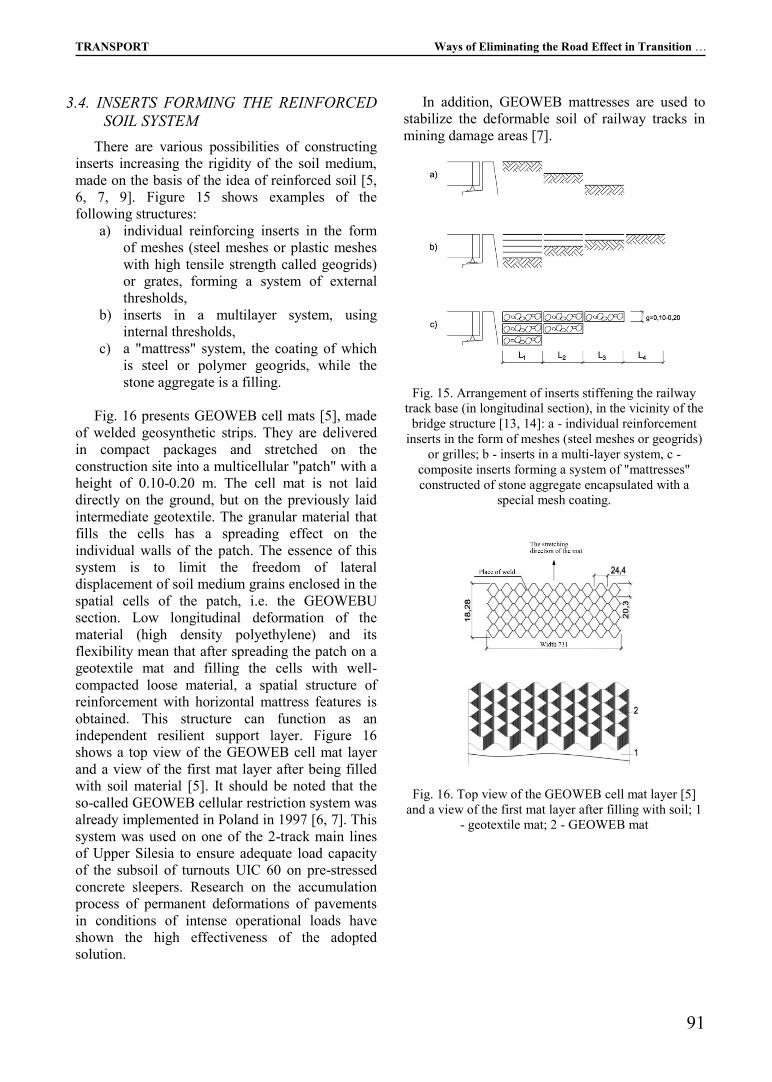
3.4. INSERTS FORMING THE REINFORCED
SOIL SYSTEM
There are various possibilities of constructing
inserts increasing the rigidity of the soil medium,
made on the basis of the idea of reinforced soil [5,
6, 7, 9]. Figure 15 shows examples of the
following structures:
a) individual reinforcing inserts in the form
of meshes (steel meshes or plastic meshes
with high tensile strength called geogrids)
or grates, forming a system of external
thresholds,
b) inserts in a multilayer system, using
internal thresholds,
c) a "mattress" system, the coating of which
is steel or polymer geogrids, while the
stone aggregate is a filling.
Fig. 16 presents GEOWEB cell mats [5], made
of welded geosynthetic strips. They are delivered
in compact packages and stretched on the
construction site into a multicellular "patch" with a
height of 0.10-0.20 m. The cell mat is not laid
directly on the ground, but on the previously laid
intermediate geotextile. The granular material that
fills the cells has a spreading effect on the
individual walls of the patch. The essence of this
system is to limit the freedom of lateral
displacement of soil medium grains enclosed in the
spatial cells of the patch, i.e. the GEOWEBU
section. Low longitudinal deformation of the
material (high density polyethylene) and its
flexibility mean that after spreading the patch on a
geotextile mat and filling the cells with well-
compacted loose material, a spatial structure of
reinforcement with horizontal mattress features is
obtained. This structure can function as an
independent resilient support layer. Figure 16
shows a top view of the GEOWEB cell mat layer
and a view of the first mat layer after being filled
with soil material [5]. It should be noted that the
so-called GEOWEB cellular restriction system was
already implemented in Poland in 1997 [6, 7]. This
system was used on one of the 2-track main lines
of Upper Silesia to ensure adequate load capacity
of the subsoil of turnouts UIC 60 on pre-stressed
concrete sleepers. Research on the accumulation
process of permanent deformations of pavements
in conditions of intense operational loads have
shown the high effectiveness of the adopted
solution.
In addition, GEOWEB mattresses are used to
stabilize the deformable soil of railway tracks in
mining damage areas [7].
Fig. 15. Arrangement of inserts stiffening the railway
track base (in longitudinal section), in the vicinity of the
bridge structure [13, 14]: a - individual reinforcement
inserts in the form of meshes (steel meshes or geogrids)
or grilles; b - inserts in a multi-layer system, c -
composite inserts forming a system of "mattresses"
constructed of stone aggregate encapsulated with a
special mesh coating.
Fig. 16. Top view of the GEOWEB cell mat layer [5]
and a view of the first mat layer after filling with soil; 1
- geotextile mat; 2 - GEOWEB mat

Ways of Eliminating the Road Effect in Transition … Logistics and Transport No 4(44)/2019
92
4. RESEARCH ON THE EFFECTS OF
INCREASING THE TRACK-BED
STIFFNESS WITH HORIZONTAL
INSERTS
The possibilities of strengthening the non-
cohesive soil medium (i.e. increasing the
deformation modulus value) using special inserts
were recognized by the authors of this article,
based on physical models of the subsoil layer,
made on a laboratory scale. The tests consisted in
measuring vertical deformations of reinforced soil
models (essentially sand), generated by vertical
static load (Fig. 17). The samples were reinforced
with FORTRAC® R90 / 90-20T polyester
geogrids in the shape of a 0.50 m square. The main
parameters of technical characteristics are as
follows [1]: 20x20 mm square mesh size, tensile
strength in the direction of the central axes min. 90
kN / m, maximum elongation at break in both
directions 10%. Based on the estimated vertical
deformations of soil samples, at external load
(analogous to the operational load), in the form of
vertical static pressure in the range of 0 ÷ 0.15
MPa, the deformation modules were calculated
according to the formula (Table 1):
E0 = pz h sv-1
(7)
where:
pz = 0.15 MPa - maximum load of the soil
sample,
h = 0.42 m - sample height,
sv - vertical deformation of the sample.
The research was of the comparative character
- the results were compared with the results
obtained for the standard, i.e. the model without
reinforcement. The values of deformation modules
for some models are given in Table 1. An increase
in the values of deformation modules of subgrade
models (increase in stiffness) has been shown,
depending on the number and arrangement of
inserts.
In the case of models with reinforcement in the
form of a "mattress", an additional enlargement of
the deformation module by approx. 20% was
found, compared to the analogous (in terms of
location) reinforcement system with isolated
inserts.
Fig. 17. Diagrams of research models: A - model with a
single insert, B - with two, C - with three inserts, D -
composite reinforcement in the form of a "mattress", H -
height of the model, z - level of location of
reinforcement inserts, index " n "with the parameter z
means the reinforcement insert number [14].
Table 1. Values of deformation modules for selected
models with isolated reinforcements. For comparison,
the deformation modulus of the reference model (with-
out reinforcement) was given [14].
Model
Location of
reinforcement
inserts [m]
Deformation
module
E0 [MPa]
Single reinforcement z1 = 0.03 3.94
Single reinforcement z2 = 0.09 3.00
Single reinforcement z3 = 0.15 2.77
Single reinforcement z4 = 0.21 2.34
Single reinforcement z5 = 0.27 2.30
Single reinforcement z6 = 0.33 2.02
Single reinforcement z7 = 0.39 1.91
Double reinforcement z1. z6 5.19
Double reinforcement z1. z6 4.21
Double reinforcement z2. z6 3.89
Double reinforcement z3. z6 3.21
Double reinforcement z4. z6 2.93
Double reinforcement z5. z6 2.69
Double reinforcement z1, z7 5.08
Triple reinforcement z1, z4, z7 5.90
Triple reinforcement z2, z4, z6 5.73
Triple reinforcement z3, z4, z5 5.47
unreinforced --------- 1.84
5. SUMMARY REMARKS
The subject of the article - in addition to the
presentation of currently used transition episode
solutions - are proprietary solution suggestions.
These technologies can be classified as economical
because they are characterized by features of
significant importance (in relation to traditional
reinforced concrete transition slabs), especially in
the case of the need to quickly rebuild damaged
(e.g. as a result of flooding) embankments adjacent
to bridge structures. The advantages of these
solutions include, among others: relatively short
construction time and uncomplicated assembly

TRANSPORT Ways of Eliminating the Road Effect in Transition …
93
(which results in low implementation costs), no
requirements for specialized equipment
(components of the structure should be assessed as
quite light) and qualified personnel.
It is necessary to emphasize the desirability of
proposing the construction of transition inserts
from used railway sleepers being waste materials.
The recycling of used accessories proposed in the
article is the most accurate solution in the light of
the applicable environmental protection criteria.
Among the proposed transition inserts are also
the three-dimensional GEOWEB cell-mats. The
effectiveness of these strengthening inserts has
been confirmed, among others in Upper Silesia,
performing field tests on the deformation of the
railway main track in the operation process, i.e.
subjecting the track (with cell-mats in the ground)
to dynamic operational load [6]. In addition,
GEOWEB cell-mats are also used in practice to
stabilize the railway track in mining damage
areas [7].
One of the chapters of this article concerns own
research carried out by the authors. In order to
demonstrate the impact of the use of horizontally
spaced reinforcing inserts on the growth of the
subgrade deformation module, the results of tests
performed on physical models of the layer of the
soil loaded with static pressure were signalled in a
synthetic form. Particularly noteworthy are the
composite inserts (mattress type), which generated
soil strengthening effects about 20% larger
compared to the system of isolated inserts. The
conclusions derived from these studies can be
treated as a scientific pillar, justifying the
advisability of the adopted concepts of transition
zone development solutions.
REFERENCES
[1] Ajdukiewicz J., Rekonstrukcja i wzmocnienie
podbudowy północnej jezdni autostrady A-4,
Raport Techniczny – po 5 latach. Przedsiębiorstwo
Realizacyjne INORA® Sp. z o.o., Gliwice 2004.
[2] Czudek H., Jaworowska B., Pisarczyk S.,
Radomski W., Budowa mostów, vol. 1,
Wydawnictwa Szkolne i Pedagogiczne, Warszawa
1993.
[3] Dembicki E., Parcie, odpór i nośność gruntu,
Wydawnictwo Arkady, Warszawa 1999.
[4] Id-3 Warunki Techniczne Utrzymania Podtorza
Kolejowego, PKP Polskie Linie Kolejowe S.A.,
Warszawa 2009.
[5] Jarominiak A., Lekkie konstrukcje oporowe,
Wydawnictwa Komunikacji i Łączności,
Warszawa 2010.
[6] Kłosek K., Gad P., Wróbelski W., Wykorzystanie
GEOWEBU do wzmocnienia słabonośnego
podtorza rozjazdów na podrozjazdnicach
betonowych, [in:] IX Konferencja Naukowa
„Drogi Kolejowe”, Kraków, Politechnika
Krakowska, Wydział Inżynierii Lądowej, Kraków
1997, pp. 99-110.
[7] Kłosek K., Wzmacnianie podtorza górniczego
geosyntetykami, „Przegląd Komunikacyjny”, 31
(2016)/11, pp. 27-30.
[8] Leonhardt F., Podstawy budowy mostów
betonowych, Wydawnictwa Komunikacji i
Łączności, Warszawa 1982.
[9] Mazur S., Surowiecki A., Opracowanie sposobu
zabudowy warstwy wzmacniającej z gruntu
zbrojonego na przejeździe kolejowo-drogowym,
Boreczek-Strzelin, Raport Serii SPR, No. 15,
Instytut Inżynierii Lądowej, Politechnika
Wrocławska, Zlecenie Nr 311869 DDOKP, etap
I., Wrocław 1986.
[10] Piotrowski A., Surowiecki A., Strefa przejściowa
toru kolejowego w obrębie przepustów, [in:]
Materiały III Konferencji Naukowo-Technicznej
„Drogi Kolejowe“, Politechnika Krakowska,
Kraków-Muszyna, 3-5 października Kraków 1985,
vol. 2, pp. 109-119. 1985.
[11] Rozporządzenie Ministra Infrastruktury i Rozwoju
z dn. 5.06.2014 r. zmieniające rozporządzenie w
sprawie warunków technicznych jakim powinny
odpowiadać budowle kolejowe i ich usytuowanie.
Dz.U. RP, Warszawa, 30.06.2014, pos. 867.
[12] Skrzyński E., Podtorze kolejowe. ZPK, WAT, PKP
PLK S.A., Kolejowa Oficyna Wydawnicza,
Warszawa 2010.
[13] Surowiecki A., Sposoby likwidacji efektu
progowego w strefach przejściowych z dróg na
obiekty mostowe, [in:] Materiały IV Krajowej
Konferencji Naukowo-Technicznej “Problemy
projektowania, budowy i utrzymania mostów
małych”, 2-3.12.1999, Politechnika Wrocławska,
GDDP, ODZMRP, Dolnośląskie Wydawnictwo
Edukacyjne, Wrocław 1999.
[14] Surowiecki A., Designing of intermediate zones
from the local roads to engineering objects,
“Zeszyty Naukowe Akademii Rolniczej we
Wrocławiu. Geodezja i Urządzenia Rolne”, 379
(2000)/16, pp. 131-141.
[15] Surowiecki A., Modernizacja konstrukcji dróg
szynowych.. Badania modelowe i eksploatacyjne,
Wydawnictwo Wyższej Szkoły Oficerskiej Wojsk
Lądowych im. gen. Tadeusza Kościuszki,
Wrocław 2012.
[16] Szczygieł J., Mosty betonowe, Wydawnictwa
Komunikacji i Łączności, Warszawa 1978.
[17] Towpik K., Koleje dużych prędkości.
Infrastruktura drogi kolejowej, Oficyna
Wydawnicza Politechniki Warszawskiej,
Warszawa 2012.
Ways of Eliminating the Road Effect in Transition … Logistics and Transport No 4(44)/2019
94
[18] Towpik K., Infrastruktura transportu szynowego,
Oficyna Wydawnicza Politechniki Warszawskiej,
Warszawa 2017.
Zenon Zamiar
The International University of Logistics and
Transport in Wrocław, Poland
Andrzej Surowiecki
The International University of Logistics
and Transport in Wrocław, Poland
Piotr Saska
The International University of Logistics
and Transport in Wrocław, Poland