wcdma power control
DESCRIPTION
Huawei Power Control OptiTRANSCRIPT
Course OWJ103103
WCDMA Power Control
ISSUE 1.0

OWJ103103 WCDMA Power Control ISSUE1.0 Table of Contents
Confidential Information of Huawei. No Spreading without Permission
i
Table of Contents
Overview.............................................................................................................................................1 Chapter 1 Analysis on Power Control Management Principle and Protocol ..............................2
1.1 Basic Principle of Power Control ...........................................................................................2 1.1.1 Power Control Methods for Various Physical Channels .............................................2 1.1.2 Open Loop Power Control...........................................................................................2 1.1.3 Fast Power Control .....................................................................................................2 1.1.4 Outer Loop Power Control ..........................................................................................3 1.1.5 Slow Power Control.....................................................................................................5
1.2 Analysis of Power Control Process........................................................................................5 1.2.1 Open Loop Power Control on PRACH........................................................................5 1.2.2 Open Loop Power Control of Uplink DPCCH..............................................................6 1.2.3 Power Control of Uplink Dedicated Channel DPCCH and DPDCH............................6 1.2.4 Power Control of Downlink Dedicated Channel DPCH...............................................9 1.2.5 Power Configuration of Other Channels ...................................................................12
Chapter 2 Power Management Parameters ..................................................................................13 2.2 UE Power Management Parameter.....................................................................................16
2.2.1 Power Offset Pp-m....................................................................................................16 2.2.2 Constant Value..........................................................................................................17 2.2.3 PRACH Power Ramp Step .......................................................................................17 2.2.4 Preamble Retrans Max .............................................................................................17 2.2.5 DPCCH Power Offset................................................................................................17 2.2.6 PC Preamble .............................................................................................................18 2.2.7 TPC Step Size...........................................................................................................18 2.2.8 Maximum Allowed UL Tx Power (MP) ......................................................................18
2.3 NodeB Power Management Parameter...............................................................................19 2.3.1 PO1 ...........................................................................................................................19 2.3.2 PO2 ...........................................................................................................................20 2.3.3 PO3 ...........................................................................................................................20 2.3.4 FDD TPC DL Step Size.............................................................................................20 2.3.5 Maximum Uplink SIR.................................................................................................20 2.3.6 Minimum Uplink SIR..................................................................................................21 2.3.7 Maximum DL Tx Power.............................................................................................21 2.3.8 Minimum DL Tx Power..............................................................................................22 2.3.9 Primary CPICH Power ..............................................................................................22
2.4 Others ..................................................................................................................................22 2.4.1 Outer Loop Power Control Adjustment Period (SirAdjustPeriod) .............................22 2.4.2 Outer Loop Power Control Adjustment Step (SirAdjustStep) ...................................22 2.4.3 Outer Loop Power Control Adjustment Factor (SirAdjustFactor)..............................23 2.4.4 Maximum SIR StepUp (MaxSirStepUp) ....................................................................23 2.4.5 Maximum SIR StepDown (MaxSirStepDown)...........................................................23 2.4.6 BLERtarget................................................................................................................23
OWJ103103 WCDMA Power Control ISSUE1.0 List of Tables
Confidential Information of Huawei. No Spreading without Permission
ii
List of Tables
Table 1-1 Power control methods adopted for various physical channels................................. 2
Table 1-2 Channels with power configured during cell setup .................................................. 12
TABLE 1-3 Channels with power configured during common channel configuration.............. 12
Table 2-1 Power management parameters (modifiable to network optimisation engineers)... 13
Table 2-2 Power management parameters (modification by network optimisation engineers is not recommended) ........................................................................................................... 15
Table 2-3 Initial and maximum target SIR value ...................................................................... 20
Table 2-4 Max. & min. downlink transmission power configuration ......................................... 21
OWJ103103 WCDMA Power Control ISSUE1.0 Overview
Confidential Information of Huawei. No Spreading without Permission
1
Overview
In WCDMA, power control strategies including open-loop power control and closed-loop power control fast power control and slow power control are adopted, which can well overcome the influences of unfavorable factors such as fast fading on radio channels to guarantee the transmission quality.
This document contains two parts. The first part (Section 2) describes the power control principle and the relevant protocols, and the second part (Section 3) briefly describes the meaning of each parameter and relevant algorithms.
This document is suitable for network planning engineers to study.
OWJ103103 WCDMA Power Control ISSUE1.0 Chapter 1 Analysis on Power Control Management Principle
and Protocol
Confidential Information of Huawei. No Spreading without Permission
2
Chapter 1 Analysis on Power Control Management Principle and Protocol
*Note: The content of this section is described in detail in [4].
1.1 Basic Principle of Power Control
1.1.1 Power Control Methods for Various Physical Channels
See the following table:
Table 1-1 Power control methods adopted for various physical channels
Physical channel
Open loop power control
Inner loop power control
Outer loop power control
Slow power control
No power control process, power is
specified by upper layers.
DPDCH X X DPCCH X X X PCCPCH X SCCPCH X PRACH X AICH X PICH X
1.1.2 Open Loop Power Control
For an uplink channel, the UE estimates the signals path loss by measuring the downlink channel signals, and then identifies the transmission power on the uplink channel. This power control method is rather inaccurate, because in the FDD mode, fast fading of the uplink channel doesn’t correlate with fast fading of the downlink channel, But in the range of a cell, signal fading caused by fast fading is usually more serious than that caused by propagation loss. Therefore, open loop power control is applied only at the beginning of connection setup, generally for setting the initial power.
For a downlink channel, the network sets the initial transmission power of the downlink channel according to the UE measurement reports.
1.1.3 Fast Power Control
Fast power control is a kind of closed-loop power control, which is described below through the example of fast power control of uplink channel.
OWJ103103 WCDMA Power Control ISSUE1.0 Chapter 1 Analysis on Power Control Management Principle
and Protocol
Confidential Information of Huawei. No Spreading without Permission
3
After NodeB receives a signal from the UE, it estimates the signal-to-interference ratio (SIR) of this signal. Then, NodeB compares the signal-to-interference ratio with the preset target signal-to-interference ratio (SIRtarget). If the received SIR is smaller than SIRtarget, NodeB will inform the UE through the downlink dedicated control channel to increase the transmitting power; on the contrary, if the received SIR is greater than SIRtarget, NodeB will inform the UE through downlink dedicated control channel to decrease transmitting power. The whole control process is equivalent to a negative feedback process, which can make the SIR of the received signal fluctuate near the SIRtarget.
The fast power control process on the downlink channel is the same with that on the uplink channel, but the purpose is different. Power control on the uplink channel is mainly to overcome the near-far effect. The downlink channels have not the near-far effect problem, and downlink channel power control is to conquer Rayleigh fading and the interferences of adjacent cells.
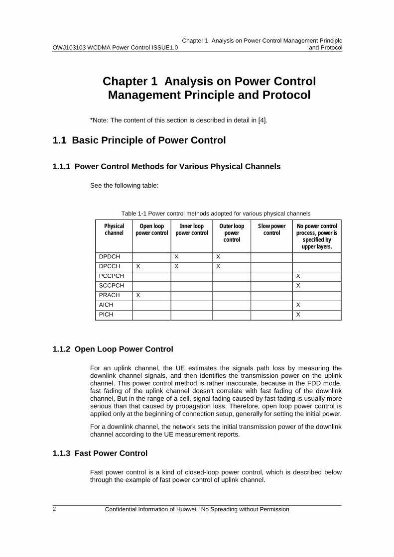
On the dedicated control channel (DPCCH), each timeslot has its power control part (TPC). In WCDMA, the period of a physical frame is 10ms, and each physical frame has 15 timeslots, so the maximum frequency of power control is 1.5 KHz (the frame format of the downlink dedicated channel is shown is Figure 1-1.). For a UE moving at a medium or slow speed, this frequency is greater than the Rayleigh fading speed, so the transmission power can be well adjusted.
Figure 1-1 Frame Format of Downlink Dedicated Channel
The above-mentioned power control method is inner loop power control, which is directly implemented at the physical layer. It is implemented by NodeB and UE together, and RNC is not involved.
1.1.4 Outer Loop Power Control
The purpose of inner loop power control is to maintain a certain SIR of received signal when the signals reach the receiver. However, in different multi-path environments, even if the mean SIR is kept above a certain threshold, it is likely that the communication quality (BER or FER or BLER) is not satisfied. So a kind of outer loop power control mechanism is required to adjust the SIR threshold of inner loop power control dynamically in order to meet the communication quality requirement. Through the estimation of signal bit error rate (BER) or block error rate (BLER), the upper layer of RNC or UE adjusts the target signal-to-interference ratio (SIRtarget) in fast power control to accomplish the goal of power control. Since this kind of power control is accomplished through upper layer, it is called outer loop power control. When the quality of the received signals becomes bad (that is, bit error rate or block error rate
OWJ103103 WCDMA Power Control ISSUE1.0 Chapter 1 Analysis on Power Control Management Principle
and Protocol
Confidential Information of Huawei. No Spreading without Permission
4
increases), the upper layer will increase the target signal-to-interference ratio (SIRtarget) to improve the quality of received signals.
DPCHDPCHDPCHDPCH
DPCCHDPCCHDPCCHDPCCH
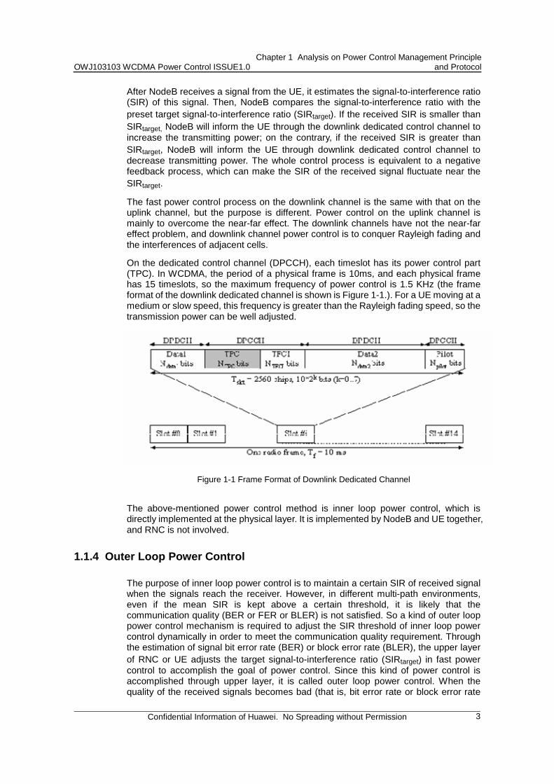
Figure 1-2 Fast power control
Figure 1-2 is a schematic diagram of downlink power control. Inner loop power control is accomplished between BS and UE. The RNC implements outer loop power control by setting BS target signal-to-interference ratio. The reason to use outer loop power control is that signal quality will be different in different environments when the signal-to-interference ratio is the same. For instance, under the same signal-to-interference ratio, the faster the UE moves, the worse the signal quality will be. As shown in Figure 1-3, generally, when mobile are still, the target signal-to-interference ratio is the lowest.
Figure 1-3 Setting of target SIR
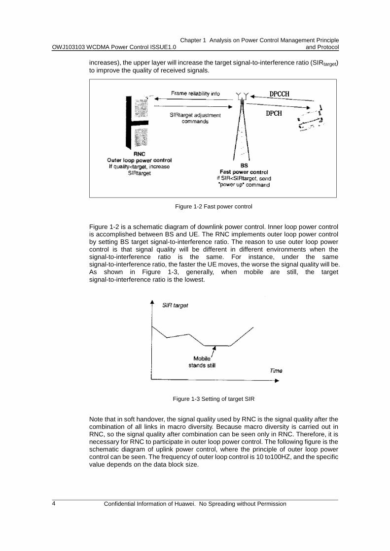
Note that in soft handover, the signal quality used by RNC is the signal quality after the combination of all links in macro diversity. Because macro diversity is carried out in RNC, so the signal quality after combination can be seen only in RNC. Therefore, it is necessary for RNC to participate in outer loop power control. The following figure is the schematic diagram of uplink power control, where the principle of outer loop power control can be seen. The frequency of outer loop control is 10 to100HZ, and the specific value depends on the data block size.
OWJ103103 WCDMA Power Control ISSUE1.0 Chapter 1 Analysis on Power Control Management Principle
and Protocol
Confidential Information of Huawei. No Spreading without Permission
5
Figure 1-4 Outer loop power control process of uplink dedicated channel
1.1.5 Slow Power Control
Slow power control is introduced in R4, which will not be described in this document. The following is just an overview.
The typical application of slow power control is network browsing. At this time, downlink sends large quantity of data packets, while uplink has only a few data such as ACK. When slow power control is adopted, commands are sent from the network side at first and are verified at the UE side. When UE is not in the soft handover state, usually, fast closed loop power control will stop, and the slow power control system will start. Under this mode, UE sends PCR (Power Control Ratio) on DPCCH at the interval of TRINT. When UE has not any information, the uplink transportation will be stopped, and it will be resumed when UE sends PCR. NodeB identifies the downlink DPCCH/DPDCH transmission power according to PCR reported by UE.
1.2 Analysis of Power Control Process
1.2.1 Open Loop Power Control on PRACH
1. PRACH Preamble Initial power Setting
The initial power of PRACH is set through outer loop power control. UE operation steps are as follows: 1) Read IE “Primary CPICH DL TX power” and “UL interference” and “Constant
value” from system information blocks. 2) Measure the value of CPICH_RSCP; 3) Calculate the initial value of PRACH preamble according to the following formula:
OWJ103103 WCDMA Power Control ISSUE1.0 Chapter 1 Analysis on Power Control Management Principle
and Protocol
Confidential Information of Huawei. No Spreading without Permission
6
Preamble_Initial_Power = Primary CPICH DL TX power - CPICH_RSCP + UL interference + Constant Value
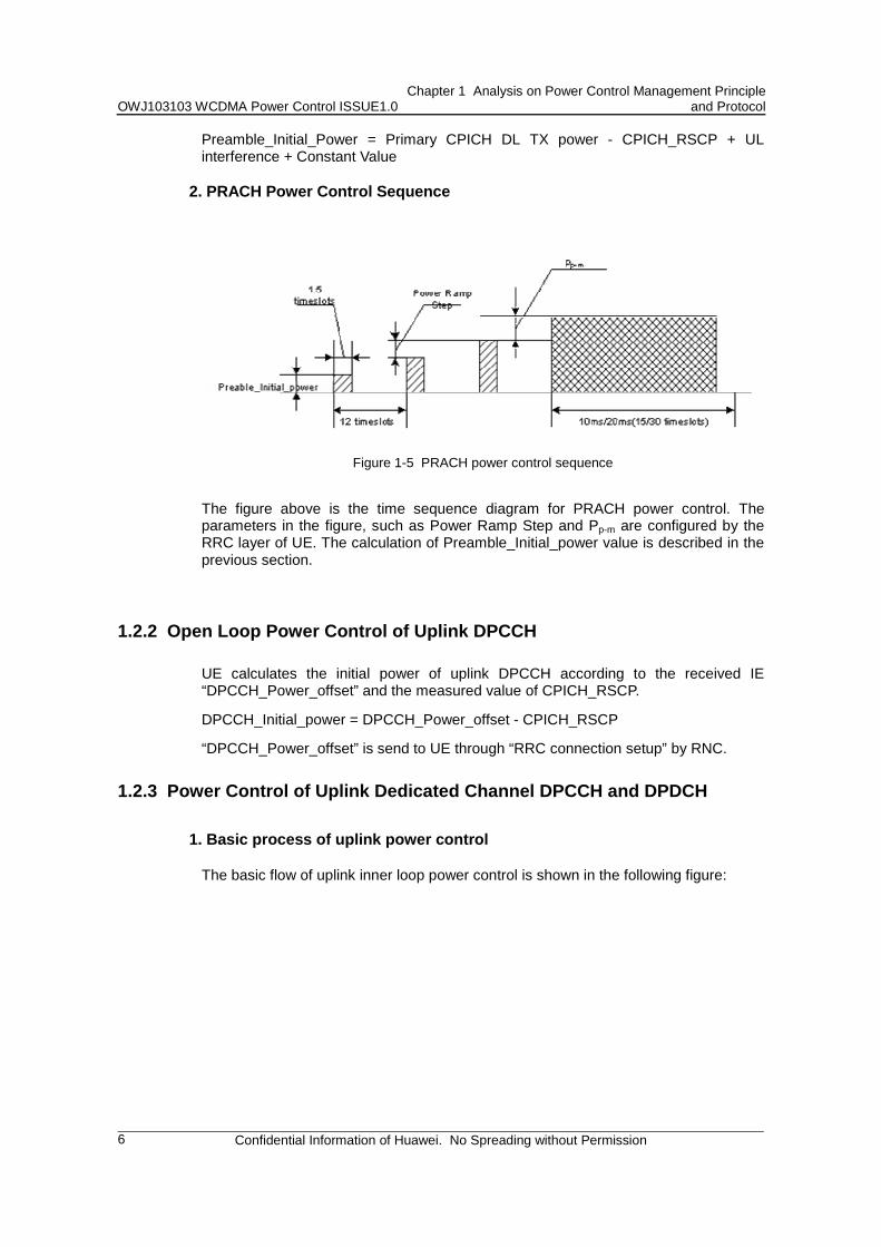
2. PRACH Power Control Sequence
Figure 1-5 PRACH power control sequence
The figure above is the time sequence diagram for PRACH power control. The parameters in the figure, such as Power Ramp Step and Pp-m are configured by the RRC layer of UE. The calculation of Preamble_Initial_power value is described in the previous section.
1.2.2 Open Loop Power Control of Uplink DPCCH
UE calculates the initial power of uplink DPCCH according to the received IE “DPCCH_Power_offset” and the measured value of CPICH_RSCP.
DPCCH_Initial_power = DPCCH_Power_offset - CPICH_RSCP
“DPCCH_Power_offset” is send to UE through “RRC connection setup” by RNC.
1.2.3 Power Control of Uplink Dedicated Channel DPCCH and DPDCH
1. Basic process of uplink power control
The basic flow of uplink inner loop power control is shown in the following figure:
OWJ103103 WCDMA Power Control ISSUE1.0 Chapter 1 Analysis on Power Control Management Principle
and Protocol
Confidential Information of Huawei. No Spreading without Permission
7
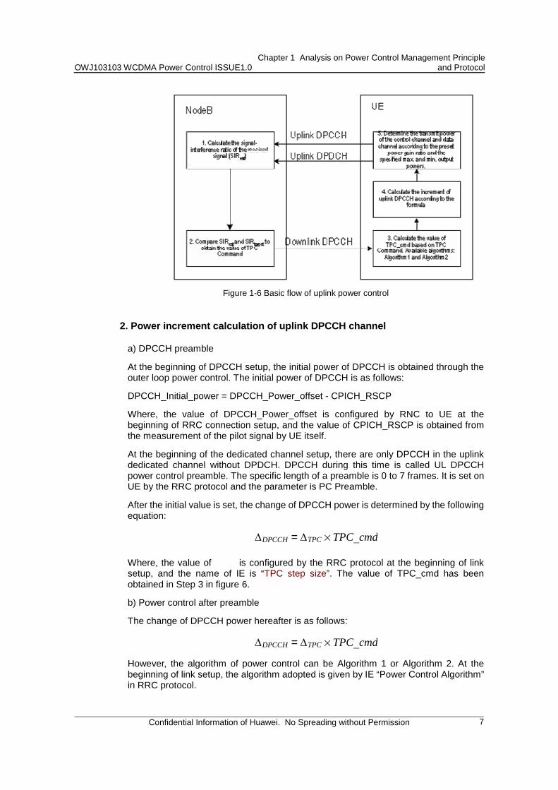
Figure 1-6 Basic flow of uplink power control
2. Power increment calculation of uplink DPCCH channel
a) DPCCH preamble
At the beginning of DPCCH setup, the initial power of DPCCH is obtained through the outer loop power control. The initial power of DPCCH is as follows:
DPCCH_Initial_power = DPCCH_Power_offset - CPICH_RSCP
Where, the value of DPCCH_Power_offset is configured by RNC to UE at the beginning of RRC connection setup, and the value of CPICH_RSCP is obtained from the measurement of the pilot signal by UE itself.
At the beginning of the dedicated channel setup, there are only DPCCH in the uplink dedicated channel without DPDCH. DPCCH during this time is called UL DPCCH power control preamble. The specific length of a preamble is 0 to 7 frames. It is set on UE by the RRC protocol and the parameter is PC Preamble.
After the initial value is set, the change of DPCCH power is determined by the following equation:
✁DPCCH = ✁TPC % TPC_cmd
Where, the value of ✁
is configured by the RRC protocol at the beginning of link setup, and the name of IE is “TPC step size”. The value of TPC_cmd has been obtained in Step 3 in figure 6.
b) Power control after preamble
The change of DPCCH power hereafter is as follows:
✁DPCCH = ✁TPC % TPC_cmd
However, the algorithm of power control can be Algorithm 1 or Algorithm 2. At the beginning of link setup, the algorithm adopted is given by IE “Power Control Algorithm” in RRC protocol.
OWJ103103 WCDMA Power Control ISSUE1.0 Chapter 1 Analysis on Power Control Management Principle
and Protocol
Confidential Information of Huawei. No Spreading without Permission
8
3. Algorithm 1 and Algorithm 2 for power control
There are two kinds of power control algorithms for up link dedicated channel DPCCH.
a) Algorithm 1:
If a UE is not in soft handover and there is only one TPC command for every timeslot, then, when TPC Command = 0, TPC _cmd = -1; when TPC Command = 1, TPC_cmd =1.
But if a UE is in soft handover, there are two steps for power control. The first step: Combine TPC commands of RLs belonging to the same RLS (Radio Link Set) (The TPC commands of all RLs in the same RLS are the same) and get TPCs. If there are N RLSs, there will be N TPCs in a timeslot. The second step: Make soft decision for all the received TPCis (I = 1, 2…..N), and obtain the corresponding Wi. Then obtain the value of TPC_cmd by means of the following formula:
TPC_cmd = ✏(W1, W2, ......WN) Where, the final value of TPC_cmd is 1 or -1.
is a user-defined function . The protocol has only three limits on this function, as follows: 1) When the probability that TPC command is 0 and the probability that TPC
command is 1 are the same, the probability that TPC_cmd value is 1 should be greater than or equal to 1/(2N), while the probability that TPC_cmd value is -1 should be greater than or equal to 1/2;
2) When all TPC commands = 1, TPC_cmd = 1; 3) When all TPC commands = 0, TPC_cmd = -1. b) Algorithm 2:
Perform a power adjustment every 5 timeslots (Divide each frame equally into 3 segments to obtain 5 timeslots each segment.)
If a UE is not in soft handover and there is only one TPC command for every timeslot: 1) For the first 4 timeslots of a segment, TPC_cmd = 0. 2) For the fifth slot, the UE uses hard decisions on each of the 5 received TPC
commands as follows: If all 5 hard decisions within a set are 1 then TPC_cmd = 1 in the 5th slot;
If all 5 hard decisions within a set are 0 then TPC_cmd = -1 in the 5th slot;
Otherwise, TPC_cmd = 0 in the 5th slot.
If soft handover exists, there are two steps. The first step: Combine TPC Commands of RLs belonging to the same RLS (Radio Link Set) (The TPC commands of all RLs in the same RLS are the same). If there are N PLSs, each RLS can obtain a TPCi (I = 1, 2…..N). The second step: Divide each frame equally into 3 segments for each RLS by means of the previously mentioned method to obtain 5 timeslots each segment, and then make the decision. Finally, TPC_cmd (obtained from the previous four timeslots) = 0. In the fifth timeslot, suppose that the decision result of each RLS is TPC_tempi (i = 1, 2……N), for the previous 4 timeslots, all the TPC_tempi values = 0. TPC_cmd is obtained with the following function:
TPC_cmd(5 thslot) = ✏(TPC_tmp1, TPC_tmp2, ......TPC_tmpN)
Where is defined as:
OWJ103103 WCDMA Power Control ISSUE1.0 Chapter 1 Analysis on Power Control Management Principle
and Protocol
Confidential Information of Huawei. No Spreading without Permission
9
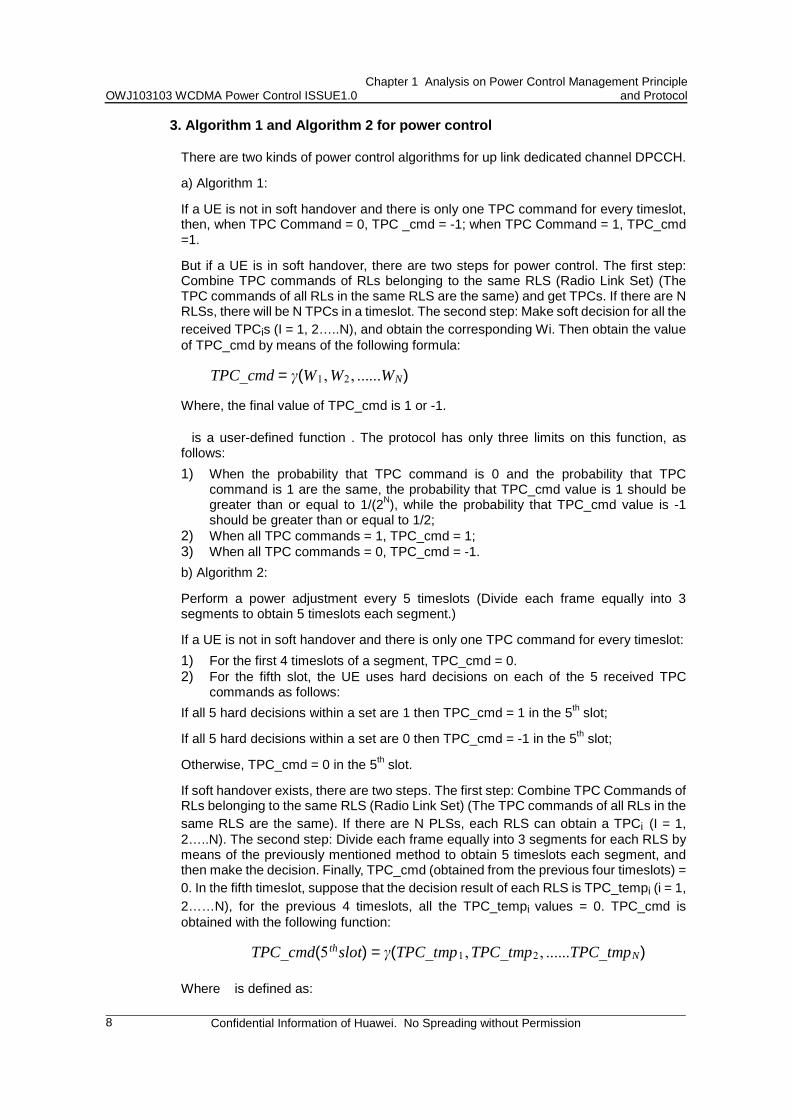
1N ✟i=1
NTPC_tempi > 0.5时,TPC_cmd = 1
1N ✟i=1
NTPC_tempi > 0.5时, TPC_cmd = −1
In other cases, TPC_cmd = 0.
4. Transmit Power of Control Channel and Data Channel
The transmission power of the control channel and the data channel depends on the preset power gain rate and the specified maximum and minimum output power. When DPCCH power is identified, DPDCH power can be obtained with power gain rate. The power gain rate is defined as follows:
Aj = ✎d✎c
Where, ✎
and ✎
are the gain factors of DPCCH and DPDCH respectively. ✎
and ✎
can be obtained through two methods: One is that RNC configures directly UE through RRC protocol (Signalled Gain Factors), and the corresponding IEs are “Gain Factor
✎”
and “Gain Factor ✎
”; the other method is to obtain ✎
and ✎
(Computed Gain Factors) of the current TFC with
✎ and ✎
of the reference TFC. As a service can have multi TFCs, for the second method, as long as
✎ and ✎
of a certain TFC are known, ✎
and ✎
of other TFCs can be obtained.
For a connection, these two methods can be used in combination. If the upper layer has configured a gain factor on a certain TFC, adopt Method 1; if the upper layer has not configured any gain factor on a certain TFC, adopt Method 2. (The IDs of the reference TFCs are set through IE “Reference TFC ID”)
1.2.4 Power Control of Downlink Dedicated Channel DPCH
1. Basic process of downlink power control
The basic flow of the downlink power control is shown in the following diagram, which involves only inner loop power control. Outer loop power control is implemented inside the UE, and it is the same as uplink outer loop power control in theory, but there is no description about it in 25 Series Protocol.
OWJ103103 WCDMA Power Control ISSUE1.0 Chapter 1 Analysis on Power Control Management Principle
and Protocol
Confidential Information of Huawei. No Spreading without Permission
10
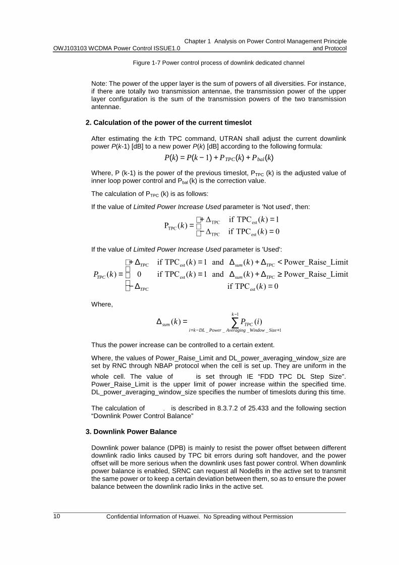
Figure 1-7 Power control process of downlink dedicated channel
Note: The power of the upper layer is the sum of powers of all diversities. For instance, if there are totally two transmission antennae, the transmission power of the upper layer configuration is the sum of the transmission powers of the two transmission antennae.
2. Calculation of the power of the current timeslot
After estimating the k:th TPC command, UTRAN shall adjust the current downlink power P(k-1) [dB] to a new power P(k) [dB] according to the following formula:
P(k) = P(k − 1) + PTPC(k) + Pbal(k) Where, P (k-1) is the power of the previous timeslot, PTPC (k) is the adjusted value of inner loop power control and Pbal (k) is the correction value.
The calculation of PTPC (k) is as follows:
If the value of Limited Power Increase Used parameter is 'Not used', then:
=−=+
=0)(TPCif∆1)(TPCif∆
)(PestTPC
estTPCTPC k
kk
If the value of Limited Power Increase Used parameter is 'Used':
=≥∆+∆=<∆+∆=
∆−
∆+=
0)(TPC ife_LimitPower_Rais)( and 1)(TPC ife_LimitPower_Rais)( and 1)(TPC if
0)(
est
est
est
kkkkk
kP TPCsum
TPCsum
TPC
TPC
TPC
Where,
∑−
+−=
=∆1
1____)()(
k
SizeWindowAveragingPowerDLkiTPCsum iPk
Thus the power increase can be controlled to a certain extent.
Where, the values of Power_Raise_Limit and DL_power_averaging_window_size are set by RNC through NBAP protocol when the cell is set up. They are uniform in the whole cell. The value of
✁ is set through IE “FDD TPC DL Step Size”.
Power_Raise_Limit is the upper limit of power increase within the specified time. DL_power_averaging_window_size specifies the number of timeslots during this time.
The calculation of k
is described in 8.3.7.2 of 25.433 and the following section “Downlink Power Control Balance”
3. Downlink Power Balance
Downlink power balance (DPB) is mainly to resist the power offset between different downlink radio links caused by TPC bit errors during soft handover, and the power offset will be more serious when the downlink uses fast power control. When downlink power balance is enabled, SRNC can request all NodeBs in the active set to transmit the same power or to keep a certain deviation between them, so as to ensure the power balance between the downlink radio links in the active set.
OWJ103103 WCDMA Power Control ISSUE1.0 Chapter 1 Analysis on Power Control Management Principle
and Protocol
Confidential Information of Huawei. No Spreading without Permission
11
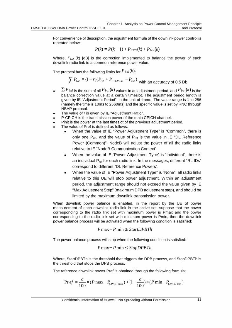
For convenience of description, the adjustment formula of the downlink power control is repeated below:
P(k) = P(k − 1) + PTPC(k) + Pbal(k) Where, Pbal (k) [dB] is the correction implemented to balance the power of each downlink radio link to a common reference power value.
The protocol has the following limits for Pbal(k): ))(1( initCPICHPrefbal PPPrP −+−= −∑ with an accuracy of 0.5 Db
! ✟ Pbal is the sum of all Pbal(k) values in an adjustment period, and Pbal(k) is the balance correction value at a certain timeslot. The adjustment period length is given by IE “Adjustment Period”, in the unit of frame. The value range is 1 to 256 (namely the time is 10ms to 2560ms) and the specific value is set by RNC through NBAP protocol.
! The value of r is given by IE “Adjustment Ratio”. ! P-CPICH is the transmission power of the main CPICH channel. ! Pinit is the power at the last timeslot of the previous adjustment period. ! The value of Pref is defined as follows:
! When the value of IE “Power Adjustment Type” is “Common”, there is only one Pref, and the value of Pref is the value in IE “DL Reference Power (Common)”. NodeB will adjust the power of all the radio links relative to IE “NodeB Communication Context”.
! When the value of IE “Power Adjustment Type” is “Individual”, there is an individual Pref for each radio link. In the messages, different “RL IDs” correspond to different “DL Reference Powers”.
! When the value of IE “Power Adjustment Type” is “None”, all radio links relative to this UE will stop power adjustment. Within an adjustment period, the adjustment range should not exceed the value given by IE “Max Adjustment Step” (maximum DPB adjustment step), and should be limited by the maximum downlink transmission power.
When downlink power balance is enabled, in the report by the UE of power measurement of each downlink radio link in the active set, suppose that the power corresponding to the radio link set with maximum power is Pmax and the power corresponding to the radio link set with minimum power is Pmin, then the downlink power balance process will be activated when the following condition is satisfied:
StartDPBThPP ≥− minmax
The power balance process will stop when the following condition is satisfied:
StopDPBThPP ≤− minmax
Where, StartDPBTh is the threshold that triggers the DPB process, and StopDPBTh is the threshold that stops the DPB process.
The reference downlink power Pref is obtained through the following formula:
)min()100
1()max(100
Pr minmax CPICHCPICH PPaPPaef −×−+−×=
OWJ103103 WCDMA Power Control ISSUE1.0 Chapter 1 Analysis on Power Control Management Principle
and Protocol
Confidential Information of Huawei. No Spreading without Permission
12
Where, PCPICHmax is the PCPICH power corresponding to Pmac, PCPICHmin is the PCPICH power corresponding to Pmin, and α is the “maximum power ratio” of the OMC parameter of the RNC maintenance console.
1.2.5 Power Configuration of Other Channels
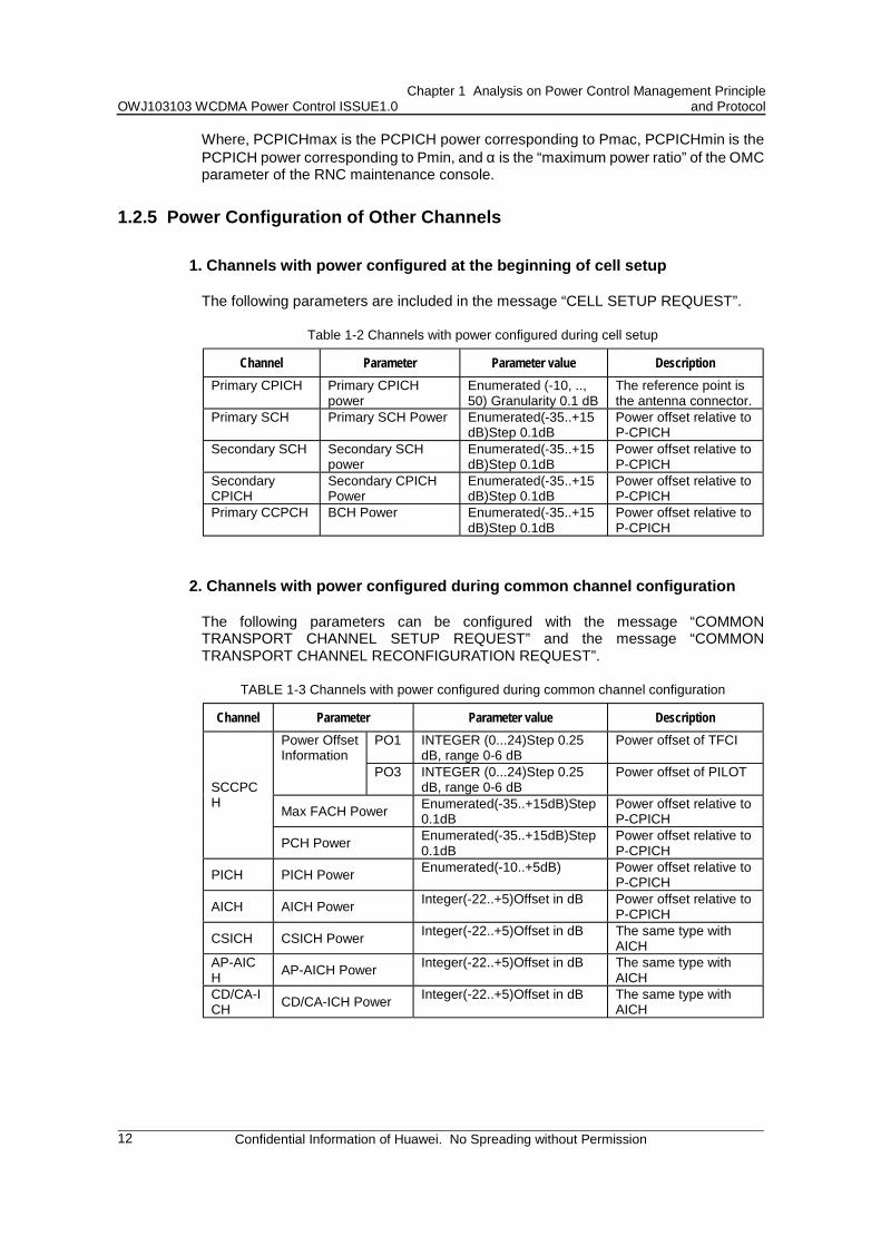
1. Channels with power configured at the beginning of cell setup
The following parameters are included in the message “CELL SETUP REQUEST”.
Table 1-2 Channels with power configured during cell setup
Channel Parameter Parameter value Description Primary CPICH Primary CPICH
power Enumerated (-10, .., 50) Granularity 0.1 dB
The reference point is the antenna connector.
Primary SCH Primary SCH Power Enumerated(-35..+15dB)Step 0.1dB
Power offset relative to P-CPICH
Secondary SCH Secondary SCH power
Enumerated(-35..+15dB)Step 0.1dB
Power offset relative to P-CPICH
Secondary CPICH
Secondary CPICH Power
Enumerated(-35..+15dB)Step 0.1dB
Power offset relative to P-CPICH
Primary CCPCH BCH Power Enumerated(-35..+15dB)Step 0.1dB
Power offset relative to P-CPICH
2. Channels with power configured during common channel configuration
The following parameters can be configured with the message “COMMON TRANSPORT CHANNEL SETUP REQUEST” and the message “COMMON TRANSPORT CHANNEL RECONFIGURATION REQUEST”.
TABLE 1-3 Channels with power configured during common channel configuration
Channel Parameter Parameter value Description PO1 INTEGER (0...24)Step 0.25
dB, range 0-6 dB Power offset of TFCI Power Offset
Information PO3 INTEGER (0...24)Step 0.25
dB, range 0-6 dB Power offset of PILOT
Max FACH Power Enumerated(-35..+15dB)Step 0.1dB
Power offset relative to P-CPICH
SCCPCH
PCH Power Enumerated(-35..+15dB)Step 0.1dB
Power offset relative to P-CPICH
PICH PICH Power Enumerated(-10..+5dB) Power offset relative to P-CPICH
AICH AICH Power Integer(-22..+5)Offset in dB Power offset relative to P-CPICH
CSICH CSICH Power Integer(-22..+5)Offset in dB The same type with AICH
AP-AICH AP-AICH Power Integer(-22..+5)Offset in dB The same type with
AICH CD/CA-ICH CD/CA-ICH Power Integer(-22..+5)Offset in dB The same type with
AICH
OWJ103103 WCDMA Power Control ISSUE1.0 Chapter 2 Power Management Parameters
Confidential Information of Huawei. No Spreading without Permission
13
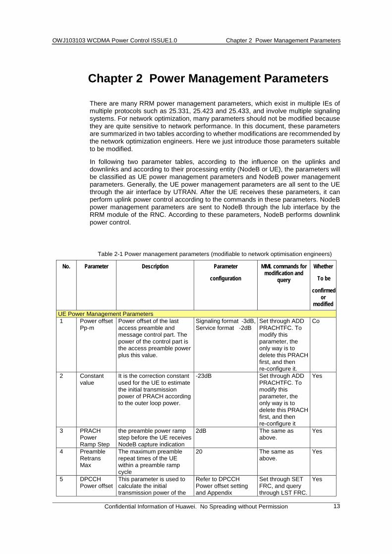
Chapter 2 Power Management Parameters
There are many RRM power management parameters, which exist in multiple IEs of multiple protocols such as 25.331, 25.423 and 25.433, and involve multiple signaling systems. For network optimization, many parameters should not be modified because they are quite sensitive to network performance. In this document, these parameters are summarized in two tables according to whether modifications are recommended by the network optimization engineers. Here we just introduce those parameters suitable to be modified.
In following two parameter tables, according to the influence on the uplinks and downlinks and according to their processing entity (NodeB or UE), the parameters will be classified as UE power management parameters and NodeB power management parameters. Generally, the UE power management parameters are all sent to the UE through the air interface by UTRAN. After the UE receives these parameters, it can perform uplink power control according to the commands in these parameters. NodeB power management parameters are sent to NodeB through the lub interface by the RRM module of the RNC. According to these parameters, NodeB performs downlink power control.
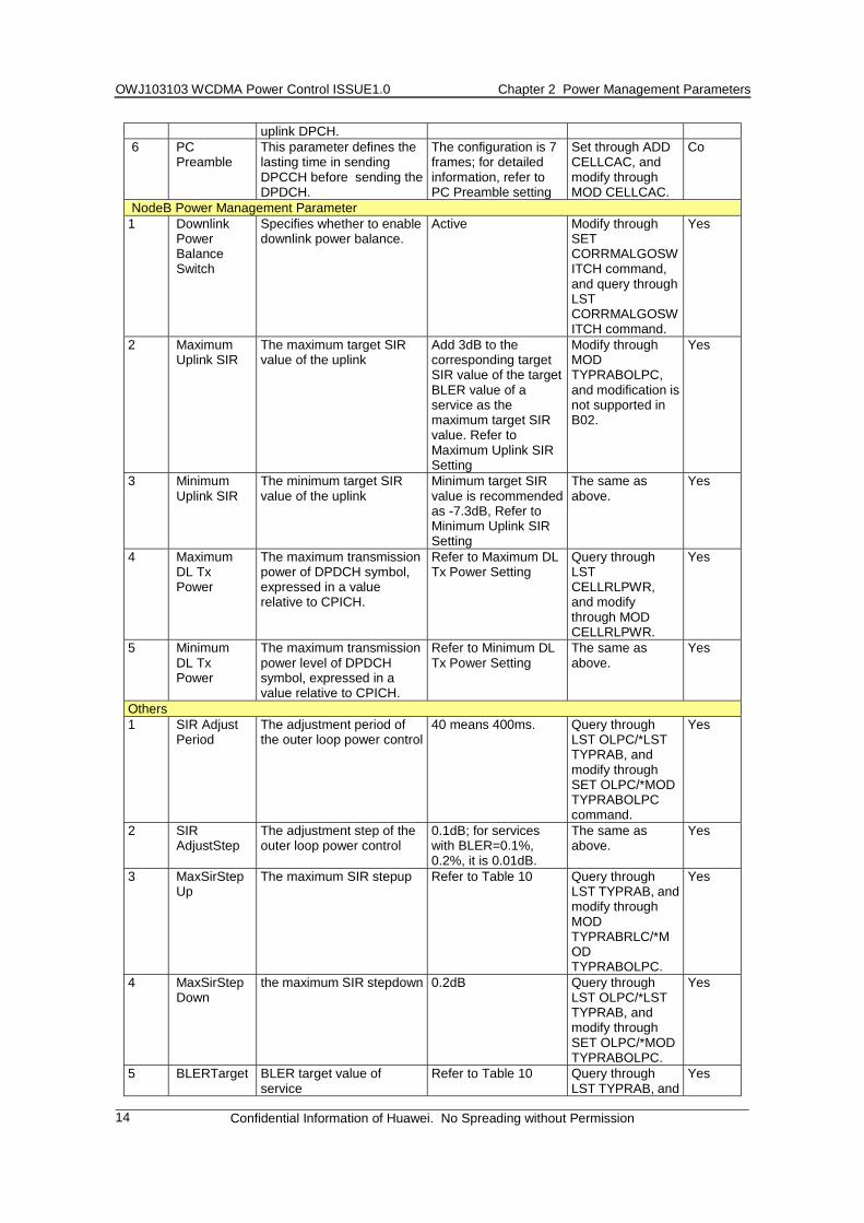
Table 2-1 Power management parameters (modifiable to network optimisation engineers)
No. Parameter Description Parameter
configuration
MML commands for modification and
query
Whether
To be
confirmed or
modified UE Power Management Parameters 1 Power offset
Pp-m Power offset of the last access preamble and message control part. The power of the control part is the access preamble power plus this value.
Signaling format -3dB, Service format -2dB
Set through ADD PRACHTFC. To modify this parameter, the only way is to delete this PRACH first, and then re-configure it.
Co
2 Constant value
It is the correction constant used for the UE to estimate the initial transmission power of PRACH according to the outer loop power.
-23dB Set through ADD PRACHTFC. To modify this parameter, the only way is to delete this PRACH first, and then re-configure it
Yes
3 PRACH Power Ramp Step
the preamble power ramp step before the UE receives NodeB capture indication
2dB The same as above.
Yes
4 Preamble Retrans Max
The maximum preamble repeat times of the UE within a preamble ramp cycle
20 The same as above.
Yes
5 DPCCH Power offset
This parameter is used to calculate the initial transmission power of the
Refer to DPCCH Power offset setting and Appendix
Set through SET FRC, and query through LST FRC.
Yes
OWJ103103 WCDMA Power Control ISSUE1.0 Chapter 2 Power Management Parameters
Confidential Information of Huawei. No Spreading without Permission
14
uplink DPCH. 6 PC
Preamble This parameter defines the lasting time in sending DPCCH before sending the DPDCH.
The configuration is 7 frames; for detailed information, refer to PC Preamble setting
Set through ADD CELLCAC, and modify through MOD CELLCAC.
Co
NodeB Power Management Parameter 1 Downlink
Power Balance Switch
Specifies whether to enable downlink power balance.
Active Modify through SET CORRMALGOSWITCH command, and query through LST CORRMALGOSWITCH command.
Yes
2 Maximum Uplink SIR
The maximum target SIR value of the uplink
Add 3dB to the corresponding target SIR value of the target BLER value of a service as the maximum target SIR value. Refer to Maximum Uplink SIR Setting
Modify through MOD TYPRABOLPC, and modification is not supported in B02.
Yes
3 Minimum Uplink SIR
The minimum target SIR value of the uplink
Minimum target SIR value is recommended as -7.3dB, Refer to Minimum Uplink SIR Setting
The same as above.
Yes
4 Maximum DL Tx Power
The maximum transmission power of DPDCH symbol, expressed in a value relative to CPICH.
Refer to Maximum DL Tx Power Setting
Query through LST CELLRLPWR, and modify through MOD CELLRLPWR.
Yes
5 Minimum DL Tx Power
The maximum transmission power level of DPDCH symbol, expressed in a value relative to CPICH.
Refer to Minimum DL Tx Power Setting
The same as above.
Yes
Others 1 SIR Adjust
Period The adjustment period of the outer loop power control
40 means 400ms. Query through LST OLPC/*LST TYPRAB, and modify through SET OLPC/*MOD TYPRABOLPC command.
Yes
2 SIR AdjustStep
The adjustment step of the outer loop power control
0.1dB; for services with BLER=0.1%, 0.2%, it is 0.01dB.
The same as above.
Yes
3 MaxSirStepUp
The maximum SIR stepup Refer to Table 10 Query through LST TYPRAB, and modify through MOD TYPRABRLC/*MOD TYPRABOLPC.
Yes
4 MaxSirStepDown
the maximum SIR stepdown 0.2dB Query through LST OLPC/*LST TYPRAB, and modify through SET OLPC/*MOD TYPRABOLPC.
Yes
5 BLERTarget BLER target value of service
Refer to Table 10 Query through LST TYPRAB, and
Yes
OWJ103103 WCDMA Power Control ISSUE1.0 Chapter 2 Power Management Parameters
Confidential Information of Huawei. No Spreading without Permission
15
modify through MOD TYPRABRLC/*MOD TYPRABOLPC.
1) For items of which the “Whether to be confirmed or modified” column is filled with “Co”, it is recommended to confirm the setting by comparing with the default value, but it is not recommended to modify the concerned parameter according to values other than the default value.
2) The default RNC version corresponding to the MML commands in the table is V100R002B02D408, and the symbol “*” means that the command is supported in B03D004, but not supported in B02.
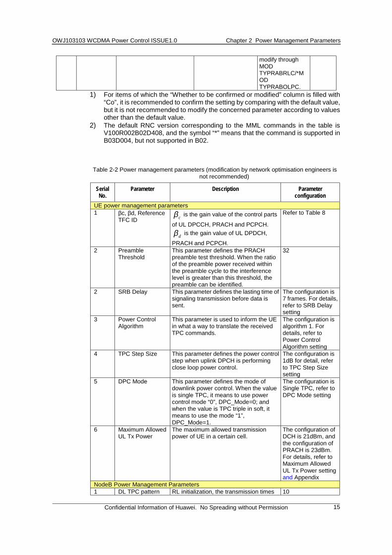
Table 2-2 Power management parameters (modification by network optimisation engineers is not recommended)
Serial No.
Parameter Description Parameter configuration
UE power management parameters 1 βc, βd, Reference
TFC ID cβ is the gain value of the control parts
of UL DPCCH, PRACH and PCPCH.
dβ is the gain value of UL DPDCH,
PRACH and PCPCH.
Refer to Table 8
2 Preamble Threshold
This parameter defines the PRACH preamble test threshold. When the ratio of the preamble power received within the preamble cycle to the interference level is greater than this threshold, the preamble can be identified.
32
2 SRB Delay This parameter defines the lasting time of signaling transmission before data is sent.
The configuration is 7 frames. For details, refer to SRB Delay setting
3 Power Control Algorithm
This parameter is used to inform the UE in what a way to translate the received TPC commands.
The configuration is algorithm 1. For details, refer to Power Control Algorithm setting
4 TPC Step Size This parameter defines the power control step when uplink DPCH is performing close loop power control.
The configuration is 1dB for detail, refer to TPC Step Size setting
5 DPC Mode This parameter defines the mode of downlink power control. When the value is single TPC, it means to use power control mode “0”, DPC_Mode=0; and when the value is TPC triple in soft, it means to use the mode “1”, DPC_Mode=1.
The configuration is Single TPC, refer to DPC Mode setting
6 Maximum Allowed UL Tx Power
The maximum allowed transmission power of UE in a certain cell.
The configuration of DCH is 21dBm, and the configuration of PRACH is 23dBm. For details, refer to Maximum Allowed UL Tx Power setting and Appendix
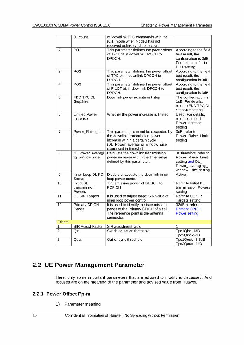
NodeB Power Management Parameters 1 DL TPC pattern RL initialization, the transmission times 10
OWJ103103 WCDMA Power Control ISSUE1.0 Chapter 2 Power Management Parameters
Confidential Information of Huawei. No Spreading without Permission
16
01 count of downlink TPC commands with the (0,1) mode when NodeB has not received uplink synchronization,
2 PO1 This parameter defines the power offset of TFCI bit in downlink DPCCH to DPDCH.
According to the field test result, the configuration is 0dB. For details, refer to PO1 setting
3 PO2 This parameter defines the power offset of TPC bit in downlink DPCCH to DPDCH.
According to the field test result, the configuration is 3dB.
4 PO3 This parameter defines the power offset of PILOT bit in downlink DPCCH to DPDCH.
According to the field test result, the configuration is 3dB.
5 FDD TPC DL StepSize
Downlink power adjustment step The configuration is 1dB. For details, refer to FDD TPC DL StepSize setting
6 Limited Power Increase
Whether the power increase is limited Used. For details, refer to Limited Power Increase setting
7 Power_Raise_Limit
This parameter can not be exceeded by the downlink transmission power increase within a certain cycle (DL_Power_averaging_window_size, expressed in timeslot)
3dB, refer to Power_Raise_Limit setting
8 DL_Power_averaging_window_size
Calculate the downlink transmission power increase within the time range defined by this parameter.
30 timeslots, refer to Power_Raise_Limit setting and DL_ Power_ averaging_ window _size setting
9 Inner Loop DL PC Status
Disable or activate the downlink inner loop power control
Active
10 Initial DL transmission Powers
Transmission power of DPDCH to PCPICH
Refer to Initial DL transmission Powers setting
11 UL SIR Targets It is used to adjust target SIR value of inner loop power control.
Refer to UL SIR Targets setting
12 Primary CPICH Power
It is used to identify the transmission power of the Primary CPICH of a cell. The reference point is the antenna connector.
33dBm, refer to Primary CPICH Power setting
Others 1 SIR Adjust Factor SIR adjustment factor 1 2 Qin Synchronization threshold Tpc1Qin: -1dB
Tpc2Qin: -2dB 3 Qout Out-of-sync threshold Tpc1Qout: -3.5dB
Tpc2Qout: -4dB
2.2 UE Power Management Parameter
Here, only some important parameters that are advised to modify is discussed. And focuses are on the meaning of the parameter and advised value from Huawei.
2.2.1 Power Offset Pp-m
1) Parameter meaning
OWJ103103 WCDMA Power Control ISSUE1.0 Chapter 2 Power Management Parameters
Confidential Information of Huawei. No Spreading without Permission
17
The power offset of the last access preamble and message control part. This value plus the access preamble power is the power of the control part. 2) Parameter setting and adjustment According to the field test results, the configuration is -3dB for the signaling transmission; -2dB for service transmission;
2.2.2 Constant Value
1) Parameter meaning This parameter is the correction constant used for the UE to estimate the initial transmission power of PRACH according to the open loop power. 2) Parameter setting and adjustment The default configuration is -23dB.
This parameter is used for the UE to estimate the initial transmission power of PRACH preamble according to the open loop power control algorithm;
2.2.3 PRACH Power Ramp Step
1) Parameter meaning This parameter is the ramp step of the preamble power when the UE has not received the capture indication from NodeB. 2) Parameter setting and adjustment The default configuration is 2.
2.2.4 Preamble Retrans Max
1) Parameter meaning This parameter is the permitted maximum preamble repeat times of the UE within a preamble ramp cycle. 2) Parameter setting and adjustment The default configuration is 20.
The product of this parameter and the above-mentioned PRACH Power Ramp Step determines the maximum ramp power of the UE within a preamble ramp cycle.
2.2.5 DPCCH Power Offset
1) Parameter meaning This parameter is used to calculate the initial transmission power of the uplink DPCH. 2) Parameter setting and adjustment The formula is given in the protocol 25.331 as follows:
DPCCH_Initial_power=DPCCH_Power_offset - CPICH_RSCP, where, CPICH_RSCP is obtained through the UE measurement.
Compare this formula with the following formula in the protocol 25.331 used to identify the PRACH preamble initial transmission power:
Preamble_initial_Power = Primary CPICH DL TX Power – CPICH RSCP+UL Interference + Constant Value, where, Primary CPICH DL TX Power (SIB5) and UL Interference (SIB 7) are broadcast in the system information blocks.
OWJ103103 WCDMA Power Control ISSUE1.0 Chapter 2 Power Management Parameters
Confidential Information of Huawei. No Spreading without Permission
18
It can be found that DPCCH_Power_offset is equivalent to Primary CPICH DL TX Power + UL Interference + Constant Value. The difference is that the Constant Value should be the target “Ec/N0_Target” of the DPCCH preamble. As the step of DPCCH_Power_offset is 2dB, the accuracy requirement of Ec/N0_Traget is not very strict, but because of the requirement of the uplink synchronization, the configuration can be bigger. The cell “Received Total Wide band Power” is contained in the signaling messages “RADIO LINK SETUP RESPONSE, RADIO LINK SET UP FAILURE, RADIO LINK ADDITION RESPONSE and RADIO LINK ADDITION FAILURE” of the lub interface and informed to CRNC. It can be used to identify the uplink interference (UL Interference).
2.2.6 PC Preamble
1) Parameter meaning This parameter defines the lasting time for transmitting DPCCH before DPCCH transmits DPDCH. 2) Parameter setting and adjustment The configuration is 7 frames. (Presently, the default configuration in RNC is 0, because NEC UE probably cannot support the configuration of 7. However, the UE of Beijing Institute of Huawei can support, so whether the configuration is 0 or 7 depends on the actual conditions of the test site.)
This parameter is originally used for the uplink and downlink power control convergence to prevent the UE from using large power at the beginning. Subsequently, some relevant proposals hold that after the UE starts DPCCH transmission, it will take NodeB some time to search this uplink signal. This delay depends on the searching procedure and propagation delay. It will be of no use starting the uplink DPDCH transmission process until this process is completed, as data cannot be received correctly at this moment, and data may even be lost; or if it is in a acknowledgement mode, retransmission may cause more serious data delay.
2.2.7 TPC Step Size
1) Parameter meaning This parameter defines the power control step when the uplink DPCH is conducting the close loop power control. 2) Parameter setting and adjustment The configuration is 1dB. Power control performance is the best when PCA=1 and the power control step is 1dB; the power control step is 1dB when PCA=2, so the configuration recommended is 1dB.
2.2.8 Maximum Allowed UL Tx Power (MP)
1) Parameter meaning The maximum allowed transmission power of the UE in a specified cell. 2) Parameter setting and adjustment Setting: DCH configuration is 21dBm, PRACH configuration is 23dBm (typical value).
ts transmission capability, this formula can be used to estimate its uplink coverage range.
OWJ103103 WCDMA Power Control ISSUE1.0 Chapter 2 Power Management Parameters
Confidential Information of Huawei. No Spreading without Permission
19
2.3 NodeB Power Management Parameter
2.3.1 PO1
1) Parameter meaning This parameter defines the power offset of the TFCI bit in the downlink DPCCH to DPDCH. 2) Parameter setting and adjustment This parameter is set to 0dB according to the field test result.
PO1, PO2 and PO3 are contained in the signaling message “RADIO LINK SETUP REQUEST”. In fact, when the power control makes DPCCH meet the communication quality requirements, the power control setting also makes DPDCH meet the requirement. If the communication quality requirement is met, reduce the transmission power as small as possible so as to increase the system capacity to the maximum. Since the number of bits in these three data fields of TPC, PILOT and TFCI are different, the power offsets for them are different.
The analysis on PO1, PO2 and PO3 configurations is as follows:
In the downlink close loop power control process, especially in soft handover, the UE implements the maximum-ratio combination only on the DPDCH in all the downlink multi-path components. However, since the DPCCH power control command is sent out from different NodeBs, the combination cannot be implemented. The UE implements SIR estimation on the PILOT domain of the downlink DPCCH and produces TPC command.
Because of the maximum-ratio combination of the downlink PILOT and TFCI, the maximum-ratio combination is not implemented in the TPC domain, so it is necessary to allow the TPC power setting higher than other domains. Here is an easy example: If non-soft handover corresponds to a set of suitable PO1, PO2 and PO3 settings, when two soft handover branches exist, the setting of the original PO2 should be somewhat higher than the power for non-soft handover.
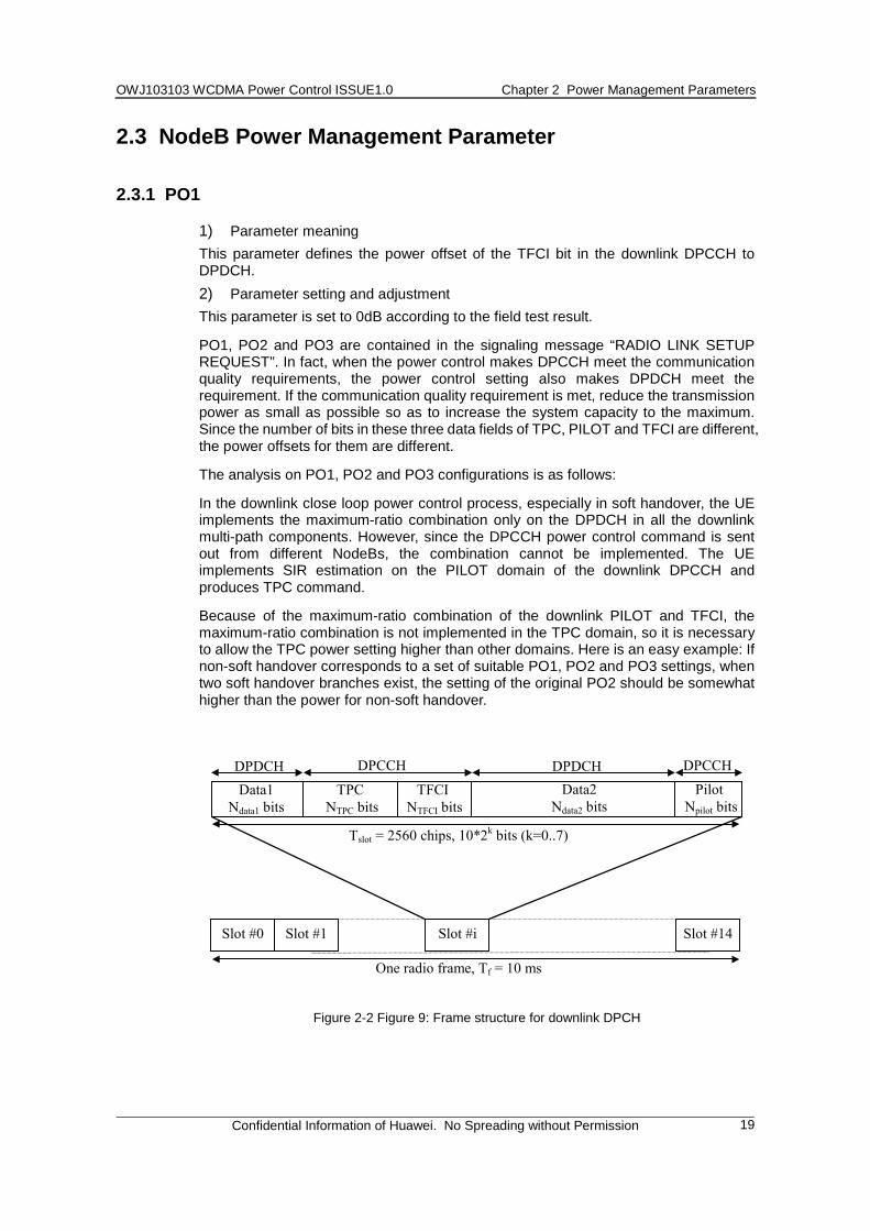
One radio frame, Tf = 10 ms
TPC NTPC bits
Slot #0 Slot #1 Slot #i Slot #14
Tslot = 2560 chips, 10*2k bits (k=0..7)
Data2Ndata2 bits
DPDCHTFCI
NTFCI bitsPilot
Npilot bitsData1
Ndata1 bits
DPDCH DPCCH DPCCH
Figure 2-2 Figure 9: Frame structure for downlink DPCH
OWJ103103 WCDMA Power Control ISSUE1.0 Chapter 2 Power Management Parameters
Confidential Information of Huawei. No Spreading without Permission
20
2.3.2 PO2
1) Parameter meaning This parameter defines the power offset of the TPC bit in the downlink DPCCH to DPDCH. 2) Parameter setting and adjustment The configuration is 3dB according to the field test result.
2.3.3 PO3
1) Parameter meaning This parameter defines the power offset of the PILOT bit in the downlink DPCCH to DPDCH. 2) Parameter setting and adjustment The configuration is 3dB according to the field test result.
2.3.4 FDD TPC DL Step Size
1) Parameter meaning The adjustment step size of the downlink power 2) Parameter setting and adjustment The default configuration is 1dB.
2.3.5 Maximum Uplink SIR
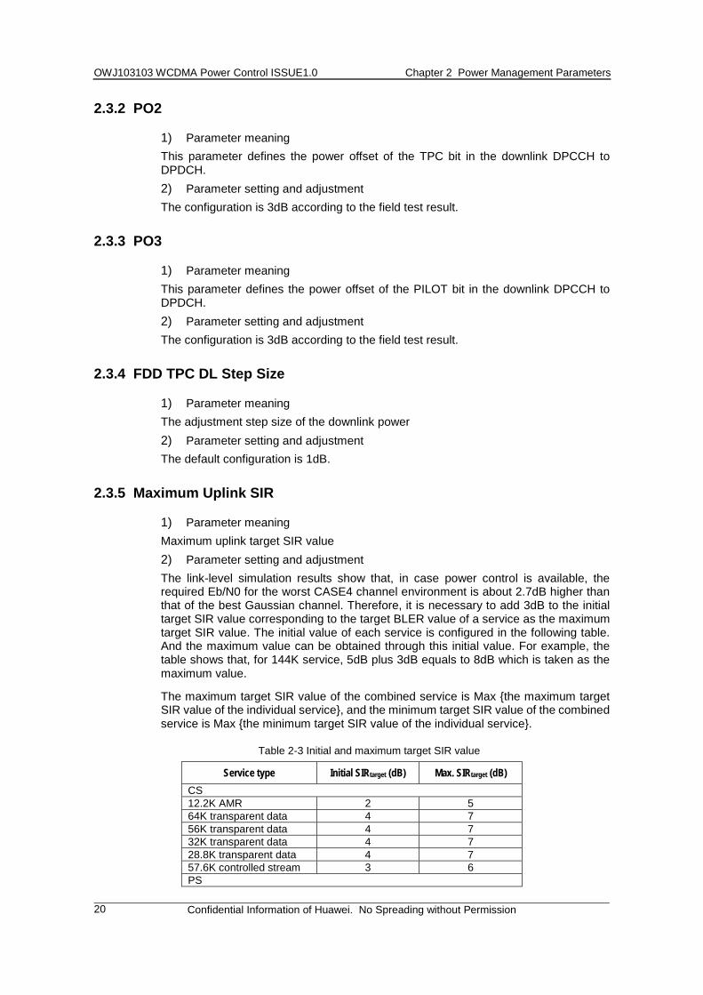
1) Parameter meaning Maximum uplink target SIR value 2) Parameter setting and adjustment The link-level simulation results show that, in case power control is available, the required Eb/N0 for the worst CASE4 channel environment is about 2.7dB higher than that of the best Gaussian channel. Therefore, it is necessary to add 3dB to the initial target SIR value corresponding to the target BLER value of a service as the maximum target SIR value. The initial value of each service is configured in the following table. And the maximum value can be obtained through this initial value. For example, the table shows that, for 144K service, 5dB plus 3dB equals to 8dB which is taken as the maximum value.
The maximum target SIR value of the combined service is Max {the maximum target SIR value of the individual service}, and the minimum target SIR value of the combined service is Max {the minimum target SIR value of the individual service}.
Table 2-3 Initial and maximum target SIR value
Service type Initial SIRtarget (dB) Max. SIRtarget (dB) CS 12.2K AMR 2 5 64K transparent data 4 7 56K transparent data 4 7 32K transparent data 4 7 28.8K transparent data 4 7 57.6K controlled stream 3 6 PS
OWJ103103 WCDMA Power Control ISSUE1.0 Chapter 2 Power Management Parameters
Confidential Information of Huawei. No Spreading without Permission
21
8K conversation 1.5 4.5 64K flow (unidirectional) 3 6 0 flow (unidirectional) 3 6 384K BE service 7 10 256K BE service 4 7 144K 2.5 5.5 128K 2 5 64K 2 5 32K 2 2 8K 2 2 Signaling 2 5
2.3.6 Minimum Uplink SIR
1) Parameter meaning The minimum uplink target SIR value 2) Parameter setting and adjustment In fact, the minimum target SIR value should also be set according to the services. For example, take the target SIR value minus 3dB as the minimum target SIR value. However, to make things simple and to avoid that the target SIR value cannot be decreased due to inappropriate limit, -7.3dB is recommended as the minimum target SIR value.
2.3.7 Maximum DL Tx Power
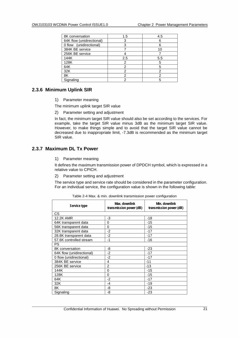
1) Parameter meaning It defines the maximum transmission power of DPDCH symbol, which is expressed in a relative value to CPICH. 2) Parameter setting and adjustment The service type and service rate should be considered in the parameter configuration. For an individual service, the configuration value is shown in the following table:
Table 2-4 Max. & min. downlink transmission power configuration
Service type Max. downlink transmission power (dB)
Min. downlink transmission power (dB)
CS 12.2K AMR -3 -18 64K transparent data 0 -15 56K transparent data 0 -15 32K transparent data -2 -17 28.8K transparent data -2 -17 57.6K controlled stream -1 -16 PS 8K conversation -8 -23 64K flow (unidirectional) -2 -17 0 flow (unidirectional) -2 -17 384K BE service 4 -11 256K BE service 2 -13 144K 0 -15 128K 0 -15 64K -2 -17 32K -4 -19 8K -8 -23 Signaling -8 -23
OWJ103103 WCDMA Power Control ISSUE1.0 Chapter 2 Power Management Parameters
Confidential Information of Huawei. No Spreading without Permission
22
2.3.8 Minimum DL Tx Power
1) Parameter meaning It defines the minimum rate level of the DPDCH symbol, and it is expressed in the relative value to CPICH. 2) Parameter setting and adjustment The value of this parameter is changed along with the specific service, and is related to the value of the parameter “Maximum DL Tx Power” and the dynamic range of the power. Their relations are shown in the following formula:
Minimum DL Tx Power=Maximum DL Tx Power - Dynamic Adjustment Range of Power Control
Where, the value of the dynamic adjustment range of power control can be 15dB.
2.3.9 Primary CPICH Power
1) Parameter meaning It is used to identify the transmission power of Primary CPICH of a cell. The reference point is the antenna connector, and its value is related to the downlink coverage requirement of the network planning. 2) Parameter setting and adjustment For a cell with large coverage, the value of this parameter should be big; on the opposite, it should be small. In a certain planned multi-cell environment, this parameter has its own fixed minimum value. If this parameter is smaller than the fixed minimum value, the coverage hole may occur when cells in the environment are under heavy load.
If this parameter is too small, it will influence directly the downlink pilot coverage range; if it is too big, it will increase the downlink interference; meanwhile, it will reduce the transmission power that can be allocated to the service and will influence the downlink capacity. In addition, the configuration of this parameter has direct influences on the distributions of the handover areas.
2.4 Others
2.4.1 Outer Loop Power Control Adjustment Period (SirAdjustPeriod)
1) Parameter meaning This parameter refers to the period during which the outer loop adjusts the target SIR value once. 2) Parameter setting and adjustment The default setting is 40, namely, 400ms.
The parameter setting is related to the changing rate of the environment. If the environment changes rapidly, this period will be short.
2.4.2 Outer Loop Power Control Adjustment Step (SirAdjustStep)
1) Parameter meaning The step of the target SIR value adjustment by the outer loop power control according to the difference between the BLER in the current period and the target BLER
OWJ103103 WCDMA Power Control ISSUE1.0 Chapter 2 Power Management Parameters
Confidential Information of Huawei. No Spreading without Permission
23
2) Parameter setting and adjustment The default configuration is 1, namely, 0.1dB.
The setting of this parameter is related to the current service. For the low bit error rate service where the BLER is 0.1% or 0.2%, we set it to 0.01dB or to be other small parameters.
2.4.3 Outer Loop Power Control Adjustment Factor (SirAdjustFactor)
1) Parameter meaning This parameter is used to correct the adjustment step of the target SIR value of the outer loop power control. 2) Parameter setting and adjustment The default setting is 1.
2.4.4 Maximum SIR StepUp (MaxSirStepUp)
1) Parameter meaning The maximum stepup of a SIR target in the outer loop power control 2) Parameter setting and adjustment For the default setting, refer to Table 10.
If this parameter is too great, the UE transmission power will probably be too large, which will produce strong interference on the uplink. If it is too small, it will probably influence on the normal outer loop power control process.
Returning
2.4.5 Maximum SIR StepDown (MaxSirStepDown)
1) Parameter meaning The maximum stepdown of a SIR target in the outer loop power control 2) Parameter setting and adjustment The default setting is 2, namely, 0.2dB.
If this parameter is set too big, NodeB will fail to receive messages properly. If it is set too small, it will probably influence the normal outer loop power control process.
Returning
2.4.6 BLERtarget
1) Parameter meaning The target BLER value of the outer loop power control 2) Parameter setting and adjustment For the default setting, refer to Table 10.
If this parameter is set too good, it will waste the network resources; if it is set too bad, it will fail to satisfy the service QoS requirements.