wdr-3124a user's manual - moxa · wdr-3124a user’s manual . ... • gsm/gprs/edge/umts/hspa...
TRANSCRIPT
WDR-3124A User’s Manual
First Edition, May 2015
www.moxa.com/product
© 2015 Moxa Inc. All rights reserved.

WDR-3124A User’s Manual
The software described in this manual is furnished under a license agreement and may be used only in accordance with the terms of that agreement.
Copyright Notice
Copyright © 2015 Moxa Inc. Reproduction without permission is prohibited.
Trademarks
The MOXA logo is a registered trademark of Moxa Inc. All other trademarks or registered marks in this manual belong to their respective manufacturers.
Disclaimer
Information in this document is subject to change without notice and does not represent a commitment on the part of Moxa. Moxa provides this document as is, without warranty of any kind, either expressed or implied, including, but not limited to, its particular purpose. Moxa reserves the right to make improvements and/or changes to this manual, or to the products and/or the programs described in this manual, at any time. Information provided in this manual is intended to be accurate and reliable. However, Moxa assumes no responsibility for its use, or for any infringements on the rights of third parties that may result from its use. This product might include unintentional technical or typographical errors. Changes are periodically made to the information herein to correct such errors, and these changes are incorporated into new editions of the publication.
Technical Support Contact Information
www.moxa.com/support
Moxa Americas Toll-free: 1-888-669-2872 Tel: +1-714-528-6777 Fax: +1-714-528-6778
Moxa China (Shanghai office) Toll-free: 800-820-5036 Tel: +86-21-5258-9955 Fax: +86-21-5258-5505
Moxa Europe Tel: +49-89-3 70 03 99-0 Fax: +49-89-3 70 03 99-99
Moxa Asia-Pacific Tel: +886-2-8919-1230 Fax: +886-2-8919-1231
Table of Contents
1. Introduction ...................................................................................................................................... 1-1 Overview ........................................................................................................................................... 1-2 Package Checklist ............................................................................................................................... 1-2 Product Features ................................................................................................................................ 1-2 Product Specifications ......................................................................................................................... 1-3 Appearance ........................................................................................................................................ 1-7 Device Dimensions .............................................................................................................................. 1-8 Connecting the Hardware..................................................................................................................... 1-8
Wiring Requirements ................................................................................................................... 1-8 Installing a SIM Card ........................................................................................................................... 1-9 Device Mounting ................................................................................................................................. 1-9
DIN-Rail Mounting ....................................................................................................................... 1-9 Wall Mounting (optional) ............................................................................................................ 1-10 Grounding the WDR-3124A ......................................................................................................... 1-11 Wiring the Redundant Power Inputs ............................................................................................. 1-12 Wiring the Relay Contact ............................................................................................................ 1-12 Wiring the Digital Inputs ............................................................................................................ 1-12
Communication Connections .............................................................................................................. 1-13 10/100BaseT(X) Ethernet Port Connection .................................................................................... 1-13 1000BaseT Ethernet Port Connection ........................................................................................... 1-13 Serial Connection ...................................................................................................................... 1-13
LED Indicators .................................................................................................................................. 1-14 Beeper ..................................................................................................................................... 1-15 Reset Button ............................................................................................................................. 1-15
2. Getting Started.................................................................................................................................. 2-1 Static and Dynamic IP Addresses .......................................................................................................... 2-2 Factory Default IP Address ................................................................................................................... 2-2 Configuration Options .......................................................................................................................... 2-2
Wireless Search Utility ................................................................................................................. 2-2 Web Console ............................................................................................................................... 2-2 Telnet Console ............................................................................................................................ 2-2 SSH Console ............................................................................................................................... 2-3 Serial Console ............................................................................................................................. 2-3
3. Web Console Configuration ............................................................................................................... 3-1 Accessing the Web Console .................................................................................................................. 3-2 Overview ........................................................................................................................................... 3-3
SIM Status ................................................................................................................................. 3-4 Basic Settings .................................................................................................................................... 3-4
System Info Settings ................................................................................................................... 3-4 Network Settings ......................................................................................................................... 3-5 Time Settings ............................................................................................................................. 3-6
Cellular Settings ................................................................................................................................. 3-7 Cellular WAN Settings .................................................................................................................. 3-7 GuaranLink ................................................................................................................................. 3-8 GPS Settings ............................................................................................................................ 3-10 OnCell Central Manager Settings ................................................................................................. 3-11
Wireless Settings .............................................................................................................................. 3-12 Operation Mode......................................................................................................................... 3-13 Basic Wireless Settings .............................................................................................................. 3-13 WLAN Security Settings.............................................................................................................. 3-15 Advanced Wireless Settings ........................................................................................................ 3-22 WLAN Certification Settings (for EAP-TLS in Client mode only) ........................................................ 3-23
Advanced Settings ............................................................................................................................ 3-24 Network Gateway Preference (in Client-Router mode) .................................................................... 3-25 DHCP Server (AP mode) ............................................................................................................. 3-26 DDNS ...................................................................................................................................... 3-27 Packet Filters ............................................................................................................................ 3-27 SNMP Agent.............................................................................................................................. 3-30 Port Forwarding ........................................................................................................................ 3-31 Virtual Private Network .............................................................................................................. 3-32 VPN System log ........................................................................................................................ 3-40
Auto Warning Settings ....................................................................................................................... 3-40 System Log .............................................................................................................................. 3-41 Syslog ..................................................................................................................................... 3-41 E-mail ...................................................................................................................................... 3-42 Relay Event Types ..................................................................................................................... 3-43 Trap ........................................................................................................................................ 3-44 SMS......................................................................................................................................... 3-45
Status ............................................................................................................................................. 3-46 Wireless Status ......................................................................................................................... 3-46 DNS Information ....................................................................................................................... 3-46 SIM Status ............................................................................................................................... 3-46 GPS Status ............................................................................................................................... 3-47 Network Status ......................................................................................................................... 3-47 Associated Client List (for AP mode only) ...................................................................................... 3-48 DHCP Client List (for AP mode only) ............................................................................................. 3-48 System Log .............................................................................................................................. 3-49 Relay Status ............................................................................................................................. 3-49 DI and Power Status .................................................................................................................. 3-49 VPN Log ................................................................................................................................... 3-50
Maintenance .................................................................................................................................... 3-50 Console Settings ....................................................................................................................... 3-50 Ping ......................................................................................................................................... 3-51 Firmware Upgrade ..................................................................................................................... 3-51 Configuration Import Export ....................................................................................................... 3-52 Load Factory Default .................................................................................................................. 3-53 Password.................................................................................................................................. 3-53 Misc. Settings ........................................................................................................................... 3-53 Remote SMS Control .................................................................................................................. 3-54
Save Configuration ........................................................................................................................... 3-55 Restart ............................................................................................................................................ 3-56 Logout............................................................................................................................................. 3-56
4. Software Installation and Configuration ........................................................................................... 4-1 Overview ........................................................................................................................................... 4-2 Wireless Search Utility ......................................................................................................................... 4-2
Installing the Wireless Search Utility .............................................................................................. 4-2 Configuring the Wireless Search Utility ........................................................................................... 4-4
A. References ........................................................................................................................................ A-1 Beacon .............................................................................................................................................. A-2 DTIM ................................................................................................................................................. A-2 Fragment ........................................................................................................................................... A-2 RTS Threshold .................................................................................................................................... A-2
B. Supporting Information .................................................................................................................... B-1 Firmware Recovery ............................................................................................................................. B-2 DoC (Declaration of Conformity) ........................................................................................................... B-2
Federal Communication Commission Interference Statement ............................................................ B-2 R&TTE Compliance Statement ....................................................................................................... B-3
C. Dynamic Domain Name Server .......................................................................................................... C-1 Overview ........................................................................................................................................... C-1
1 1. Introduction
The Moxa WDR-3124A industrial wireless device router is an ideal solution for hard-to-wire applications that use mobile equipment connected over a wireless or cellular network. The WDR-3124A combines both IEEE 802.11n and cellular technologies to offer greater flexibility in implementing wireless networks. The WDR-3124A is designed to operate at temperatures ranging from 0 to 55°C for standard models and -30 to 70°C for wide temperature models, and is rugged enough for any harsh industrial environment.
The following topics are covered in this chapter:
Overview
Package Checklist
Product Features
Product Specifications
Appearance
Device Dimensions
Connecting the Hardware
Wiring Requirements
Installing a SIM Card
Device Mounting
DIN-Rail Mounting
Wall Mounting (optional)
Grounding the WDR-3124A
Wiring the Redundant Power Inputs
Wiring the Relay Contact
Wiring the Digital Inputs
Communication Connections
10/100BaseT(X) Ethernet Port Connection
1000BaseT Ethernet Port Connection
Serial Connection
LED Indicators
Beeper
Reset Button
WDR-3124A Introduction
1-2
Overview The WDR-3124A industrial wireless device router supports both IEEE 802.11n and 3G cellular technologies to meet the growing demand for flexible wireless solutions. The WDR-3124A is compliant with industrial standards and approvals, covering operating temperature, power input voltage, surge, ESD and vibration. The two redundant DC power inputs increase the reliability of the power supply and the dual-SIM support enables redundant connections. In addition to establishing cellular connections, the WDR-3124A can be configured to operate on either the 2.4 or 5 GHz bands and is backwards-compatible with existing 802.11a/b/g/n deployments to future-proof your wireless investment.
Package Checklist The WDR-3124A is shipped with the following items. If any of these items is missing or damaged, please contact your customer service representative for assistance.
• WDR-3124A • 1 GPS connector terminator • 2 dual-band omni-directional antennas, 2 dBi, RP-SMA (male) • 1 2G/3G omni-directional antennas, 2 dBi, SMA (male) • 5 plastic RJ45 protective caps for serial console and Ethernet ports • Quick installation guide (printed) • Warranty card
NOTE The above items come with the standard WDR-3124A model, but the package contents may vary for customized versions.
Product Features All WDR-3124A models include the following features:
• GSM/GPRS/EDGE/UMTS/HSPA cellular standards
• Five-band UMTS/HSPA 850/800/900/1900/2100 MHz
• Quad-band GSM/GPRS/EDGE 850/900/1800/1900 MHz
• IEEE802.11a/b/g/n compliant
• Advanced wireless security
IEEE 802.11i support
SSID broadcast enable/disable
64-bit and 128-bit WEP encryption
WPA/WPA2-Personal and Enterprise (IEEE 802.1X/RADIUS and AES) 64-bit and 128-bit WEP/WPA/WPA2
• DIN-rail or wall mounting (option)
• GuaranLink support for a reliable cellular connectivity
• OnCell Central Manager support for private IP communication and centralized management
• RJ-45 console management
• ABC-01 for configuration import/export
• IP30 protected high-strength metal housing

WDR-3124A Introduction
1-3
Product Specifications Cellular Interface Standards: GSM/GPRS/EDGE/UMTS/HSPA Band Options: • Five-band UMTS/HSPA 800/850/900/1900/2100 MHz • Quad-band GSM/GPRS/EDGE 850/900/1800/1900 MHz HSPA Data Rate: • Downlink: Up to 14.4 Mbps • Uplink: Up to 5.76 Mbps (Category 6, 7) GPRS Data Rate: Downlink/Uplink: 236 kbps (Class 12)
Wireless Interface Standards: IEEE 802.11a/b/g/n for Wireless LAN IEEE 802.11i for Wireless Security Spread Spectrum and Modulation (typical): • DSSS with DBPSK, DQPSK, CCK • OFDM with BPSK, QPSK, 16QAM, 64QAM • 802.11b: CCK @ 11/5.5 Mbps, DQPSK @ 2 Mbps, DBPSK @ 1 Mbps • 802.11a/g: 64QAM @ 54/48 Mbps, 16QAM @ 36/24 Mbps, QPSK @ 18/12 Mbps, BPSK @ 9/6 Mbps • 802.11n: 64QAM @ 300 Mbps to BPSK @ 6.5 Mbps (multiple rates supported) Operating Channels (central frequency): WDR-3124A-EU: 2.412 to 2.472 GHz (13 channels); 5.180 to 5.240 (4 channels) WDR-3124A-US: 2.412 to 2.462 GHz (11 channels) 5.180 to 5.240 (4 channels) 5.745 to 5.825 GHz (5 channels) Security: • SSID broadcast enable/disable • 64-bit and 128-bit WEP encryption, WPA /WPA2-Personal and Enterprise (IEEE 802.1X/RADIUS, TKIP and AES) Transmission Rates: 802.11b: 1, 2, 5.5, 11 Mbps 802.11a/g: 6, 9, 12, 18, 24, 36, 48, 54 Mbps 802.11n: 6.5 to 300 Mbps (multiple rates supported) TX Transmit Power : 2.4 GHz 802.11b: Typ. 23±1.5 dBm @ 1 Mbps Typ. 20±1.5 dBm @ 5 Mbps Typ. 19±1.5 dBm @ 11 Mbps 802.11g: Typ. 20±1.5 dBm @ 6 to 24 Mbps Typ. 19±1.5 dBm @ 36 Mbps Typ. 18±1.5 dBm @ 48 Mbps Typ. 17±1.5 dBm @ 54 Mbps 802.11n: Typ. 20 dBm (± 1.5 dBm) Typ. 16 dBm (± 1.5 dBm)
WDR-3124A Introduction
1-4
5 GHz 802.11a: Typ. 20±1.5 dBm @ 6 to 24 Mbps Typ. 19±1.5 dBm @ 36 Mbps Typ. 16±1.5 dBm @ 48 Mbps Typ. 15±1.5 dBm @ 54 Mbps 802.11n: MCS0, 8 @ 20MHz: Typ. 19 dBm (± 1.5 dBm) MCS0, 8 @ 40 MHz: Typ. 18 dBm (± 1.5 dBm) MCS7, 15 @ 20 MHz: Typ. 14 dBm (± 1.5 dBm) MCS7, 15 @ 40 MHz: Typ. 14 dBm (± 1.5 dBm) RX Sensitivity: 2.4 GHz 802.11b: -92 dBm @ 1 Mbps -90 dBm @ 2 Mbps -88 dBm @ 5.5 Mbps -84 dBm @ 11 Mbps 802.11g: -87 dBm @ 6 Mbps -86 dBm @ 9 Mbps -85 dBm @ 12 Mbps -82 dBm @ 18 Mbps -80 dBm @ 24 Mbps -76 dBm @ 36 Mbps -74 dBm @ 48 Mbps -72 dBm @ 54 Mbps 802.11n: -69 dBm @ MCS15 20MHz -71 dBm @ MCS7 20MHz 5 GHz 802.11a: -87 dBm @ 6 Mbps -86 dBm @ 9 Mbps -85 dBm @ 12 Mbps -82 dBm @ 18 Mbps -80 dBm @ 24 Mbps -76 dBm @ 36 Mbps -74 dBm @ 48 Mbps -72 dBm @ 54 Mbps 802.11n: -69 dBm @ MCS15 20MHz -68 dBm @ MCS15 40MHz -71 dBm @ MCS7 20MHz -70 dBm @ MCS7 40MHz
LAN Interface Standards: IEEE 802.3 for 10BaseT IEEE 802.3u for 100BaseTX IEEE 802.3ab for 1000BaseT Speed: 10/100/1000 Mbps, Auto MDI/MDIX
WDR-3124A Introduction
1-5
Interface Cellular Antenna Connector: 1 SMA (female) for WCDMA Wireless Antenna Connectors: 2 RP-SMA (female) GNSS: 1 SMA (female), GPS (1575.42 MHz), GLONASS (1602 MHz) Ethernet: 4, 10/100/1000Mbps auto negotiation speed, F/H duplex mode and auto MDI/MDI-X connection (RJ45-type) Serial Console Port: 1, RS-232 (RJ45) Alarm Contact: 1 relay output with current carrying capacity of 1 A @ 24 VDC Digital Inputs: 2 electrically isolated inputs +13 to +30 V for state “1” +3 to -30 V for state “0” Power Input: Dual input, 12-48VDC LED Indicators: PWR1, PWR2, STATUS, FAULT, CELLULAR SIGNAL, WIFI SIGNAL, WLAN, SIM1, SIM2, 2G, 3G, GPS Ground Screw: M5 Reset Button: Power Reset/Factory Default Reset
Software Network Protocols: ICMP, TCP/IP, UDP, DHCP, Telnet, DNS, SNMP, HTTP, HTTPS, SMTP, SNTP, ARP Routing/Firewall: NAT, Port Forwarding, IP/MAC/Port Filtering VPN: • Max. Tunnel Number: 5 (Responder/Initiator) • IPSec (DES, 3DES, AES, MD5, SHA-1, DH2, DH5), PSK/X.509/RSA GPS: NMEA Others: DDNS
Management Software (Moxa Proprietary) GuaranLink: 4-tier heart-beat for reliable and persistent cellular connectivity OnCell Central Management: Large scale centralized device management over private cellular IPs Search Utility: Simple device configuration and management
SIM Interface Number of SIMs: 2 SIM Control: 3 V
Physical Characteristics Housing: Aluminum, providing IP30 protection Weight: 1280 g Installation: DIN-rail (default) or wall-mount (optional) Dimensions: 67 x 90.5 x 124 mm (2.6 x 3.52 x 4.83 inch)
Environmental Limits Operating Temperature: Standard Models: 0 to 55°C (0 to 131°F) Wide Temp. Models:-30 to 70°C (-22 to 158°F) Storage Temperature: -40 to 85°C (-40 to 185°F) Ambient Relative Humidity: 5 to 95% (30°C, non-condensing)
Power Requirements Input Voltage: 12 to 48 VDC, redundant dual inputs Connector: 4-pin removable terminal block Power Consumption: 9.6W (12V/0.7A to 48V/0.2A) Reverse Polarity Protection: Present
WDR-3124A Introduction
1-6
Standards and Certifications Safety: EN 60950-1, UL 60950-1 EMC: FCC Part 15 Subpart B EN 61000-6-2/-4 Radio: EN 301 489-1, EN 301 489-7, EN 301 511, EN 301 908, EN 300 328, EN 301 893
Reliability MTBF (mean time between failures): 382,851 hours
Warranty Warranty Period: 5 years Details: See www.moxa.com/warranty
ATTENTION
• The WDR-3124A is NOT a portable mobile device and should be located at least 20 cm away from the human body.
• The WDR-3124A is NOT designed for the general public. A well-trained technician should be enlisted to ensure safe deployment of WDR-3124A units, and to establish a wireless network.
WDR-3124A Introduction
1-7
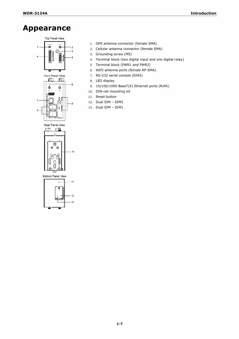
Appearance
1. GPS antenna connector (female SMA) 2. Cellular antenna connector (female SMA) 3. Grounding screw (M5) 4. Terminal block (two digital input and one digital relay) 5. Terminal block (PWR1 and PWR2) 6. WIFI antenna ports (female RP-SMA) 7. RS-232 serial console (RJ45) 8. LED display 9. 10/100/1000 BaseT(X) Ethernet ports (RJ45)
10. DIN-rail mounting kit 11. Reset button 12. Dual SIM – SIM2 13. Dual SIM – SIM1
WDR-3124A Introduction
1-8
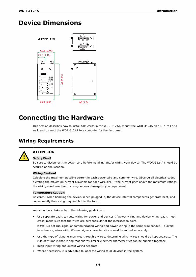
Device Dimensions
Connecting the Hardware This section describes how to install SIM cards in the WDR-3124A, mount the WDR-3124A on a DIN-rail or a wall, and connect the WDR-3124A to a computer for the first time.
Wiring Requirements
ATTENTION
Safety First! Be sure to disconnect the power cord before installing and/or wiring your device. The WDR-3124A should be secured at one location.
Wiring Caution! Calculate the maximum possible current in each power wire and common wire. Observe all electrical codes dictating the maximum current allowable for each wire size. If the current goes above the maximum ratings, the wiring could overheat, causing serious damage to your equipment.
Temperature Caution! Be careful when handling the device. When plugged in, the device internal components generate heat, and consequently the casing may feel hot to the touch.
You should also take note of the following guidelines:
• Use separate paths to route wiring for power and devices. If power wiring and device wiring paths must cross, make sure that the wires are perpendicular at the intersection point.
Note: Do not run signal or communication wiring and power wiring in the same wire conduit. To avoid interference, wires with different signal characteristics should be routed separately.
• Use the type of signal transmitted through a wire to determine which wires should be kept separate. The rule of thumb is that wiring that shares similar electrical characteristics can be bundled together.
• Keep input wiring and output wiring separate.
• Where necessary, it is advisable to label the wiring to all devices in the system.
WDR-3124A Introduction
1-9
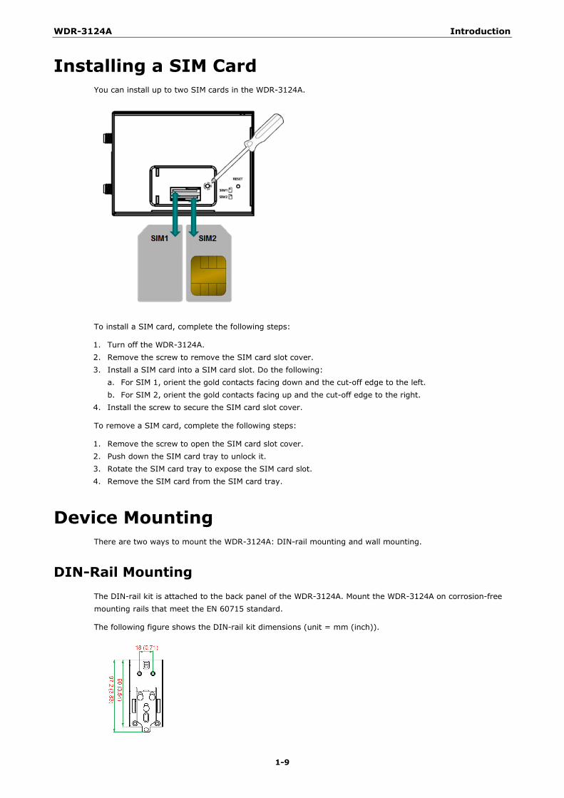
Installing a SIM Card You can install up to two SIM cards in the WDR-3124A.
To install a SIM card, complete the following steps:
1. Turn off the WDR-3124A. 2. Remove the screw to remove the SIM card slot cover. 3. Install a SIM card into a SIM card slot. Do the following:
a. For SIM 1, orient the gold contacts facing down and the cut-off edge to the left. b. For SIM 2, orient the gold contacts facing up and the cut-off edge to the right.
4. Install the screw to secure the SIM card slot cover.
To remove a SIM card, complete the following steps:
1. Remove the screw to open the SIM card slot cover. 2. Push down the SIM card tray to unlock it. 3. Rotate the SIM card tray to expose the SIM card slot. 4. Remove the SIM card from the SIM card tray.
Device Mounting There are two ways to mount the WDR-3124A: DIN-rail mounting and wall mounting.
DIN-Rail Mounting The DIN-rail kit is attached to the back panel of the WDR-3124A. Mount the WDR-3124A on corrosion-free mounting rails that meet the EN 60715 standard.
The following figure shows the DIN-rail kit dimensions (unit = mm (inch)).
WDR-3124A Introduction
1-10
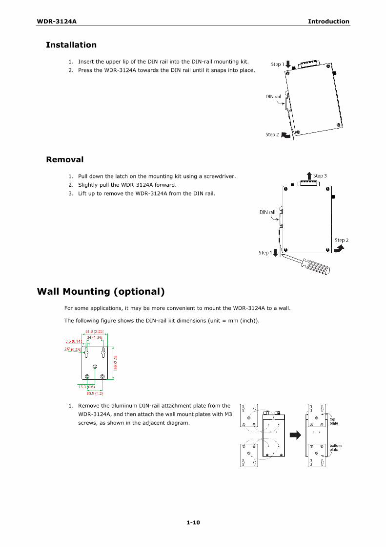
Installation
1. Insert the upper lip of the DIN rail into the DIN-rail mounting kit. 2. Press the WDR-3124A towards the DIN rail until it snaps into place.
Removal
1. Pull down the latch on the mounting kit using a screwdriver. 2. Slightly pull the WDR-3124A forward. 3. Lift up to remove the WDR-3124A from the DIN rail.
Wall Mounting (optional) For some applications, it may be more convenient to mount the WDR-3124A to a wall.
The following figure shows the DIN-rail kit dimensions (unit = mm (inch)).
1. Remove the aluminum DIN-rail attachment plate from the WDR-3124A, and then attach the wall mount plates with M3 screws, as shown in the adjacent diagram.
WDR-3124A Introduction
1-11
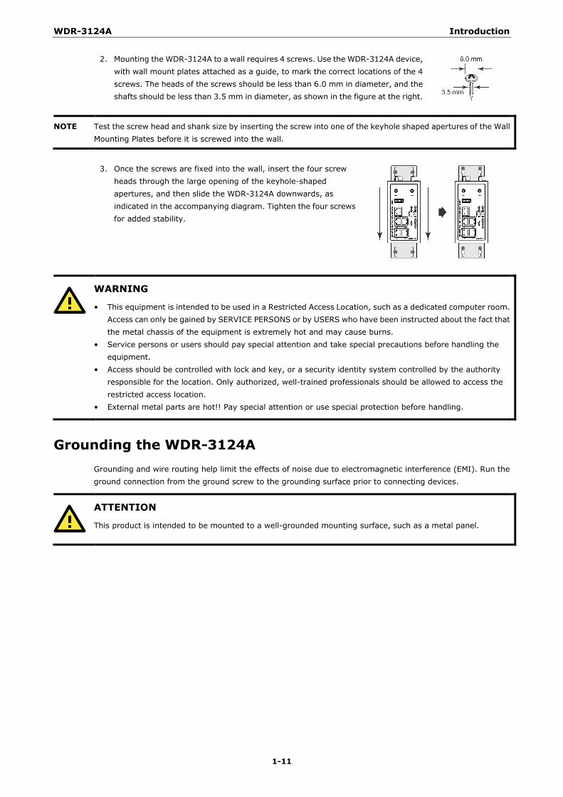
2. Mounting the WDR-3124A to a wall requires 4 screws. Use the WDR-3124A device, with wall mount plates attached as a guide, to mark the correct locations of the 4 screws. The heads of the screws should be less than 6.0 mm in diameter, and the shafts should be less than 3.5 mm in diameter, as shown in the figure at the right.
NOTE Test the screw head and shank size by inserting the screw into one of the keyhole shaped apertures of the Wall Mounting Plates before it is screwed into the wall.
3. Once the screws are fixed into the wall, insert the four screw
heads through the large opening of the keyhole-shaped apertures, and then slide the WDR-3124A downwards, as indicated in the accompanying diagram. Tighten the four screws for added stability.
WARNING
• This equipment is intended to be used in a Restricted Access Location, such as a dedicated computer room. Access can only be gained by SERVICE PERSONS or by USERS who have been instructed about the fact that the metal chassis of the equipment is extremely hot and may cause burns.
• Service persons or users should pay special attention and take special precautions before handling the equipment.
• Access should be controlled with lock and key, or a security identity system controlled by the authority responsible for the location. Only authorized, well-trained professionals should be allowed to access the restricted access location.
• External metal parts are hot!! Pay special attention or use special protection before handling.
Grounding the WDR-3124A Grounding and wire routing help limit the effects of noise due to electromagnetic interference (EMI). Run the ground connection from the ground screw to the grounding surface prior to connecting devices.
ATTENTION
This product is intended to be mounted to a well-grounded mounting surface, such as a metal panel.
WDR-3124A Introduction
1-12
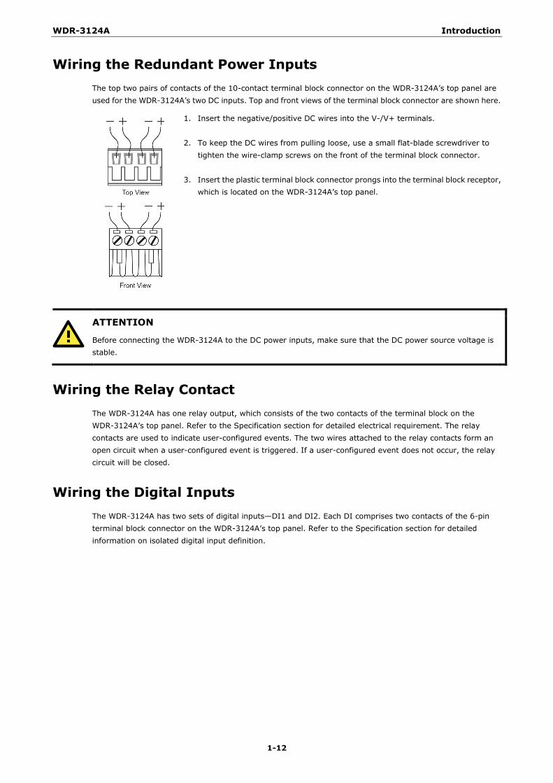
Wiring the Redundant Power Inputs The top two pairs of contacts of the 10-contact terminal block connector on the WDR-3124A’s top panel are used for the WDR-3124A’s two DC inputs. Top and front views of the terminal block connector are shown here.
1. Insert the negative/positive DC wires into the V-/V+ terminals.
2. To keep the DC wires from pulling loose, use a small flat-blade screwdriver to tighten the wire-clamp screws on the front of the terminal block connector.
3. Insert the plastic terminal block connector prongs into the terminal block receptor,
which is located on the WDR-3124A’s top panel.
ATTENTION
Before connecting the WDR-3124A to the DC power inputs, make sure that the DC power source voltage is stable.
Wiring the Relay Contact The WDR-3124A has one relay output, which consists of the two contacts of the terminal block on the WDR-3124A’s top panel. Refer to the Specification section for detailed electrical requirement. The relay contacts are used to indicate user-configured events. The two wires attached to the relay contacts form an open circuit when a user-configured event is triggered. If a user-configured event does not occur, the relay circuit will be closed.
Wiring the Digital Inputs The WDR-3124A has two sets of digital inputs—DI1 and DI2. Each DI comprises two contacts of the 6-pin terminal block connector on the WDR-3124A’s top panel. Refer to the Specification section for detailed information on isolated digital input definition.

WDR-3124A Introduction
1-13
Communication Connections This section shows the pin assignments for the Ethernet and serial ports.
10/100BaseT(X) Ethernet Port Connection The following shows the pinouts for both MDI (NIC-type) ports and MDI-X (HUB/Switch-type) ports.
MDI Port Pinouts MDI-X Port Pinouts 8-pin RJ45 Pin Signal Pin Signal
1 Tx+ 1 Rx+
2 Tx- 2 Rx-
3 Rx+ 3 Tx+
6 Rx- 6 Tx-
1000BaseT Ethernet Port Connection 1000BaseT data is transmitted on differential TRD+/- signal pairs over copper wires.
MDI/MDI-X Port Pinouts
Pin Signal 1 TRD(0)+
2 TRD(0)-
3 TRD(1)+
4 TRD(2)+
5 TRD(2)-
6 TRD(1)-
7 TRD(3)+
8 TRD(3)-
Serial Connection The WDR-3124A has one RS-232 (8-pin RJ45) console port located on the front panel. Use either an RJ45-to-DB9 or RJ45-to-DB25 cable to connect the WDR-3124A’s console port to your PC’s COM port. You may then use a console terminal program to access the WDR-3124A for console configuration.
Console Pinouts for 10-pin or 8-pin RJ45
10-Pin Description 8-Pin 1 –
2 DSR 1
3 RTS 2
4 GND 3
5 TxD 4
6 RxD 5
7 DCD 6
8 CTS 7
9 DTR 8
10 –
NOTE The pin numbers for both 8-pin and 10-pin RJ45 connectors (and ports) are typically not labeled on the connector (or port). Refer to the Pinout diagram above to see how RJ45 pins are numbered.
WDR-3124A Introduction
1-14
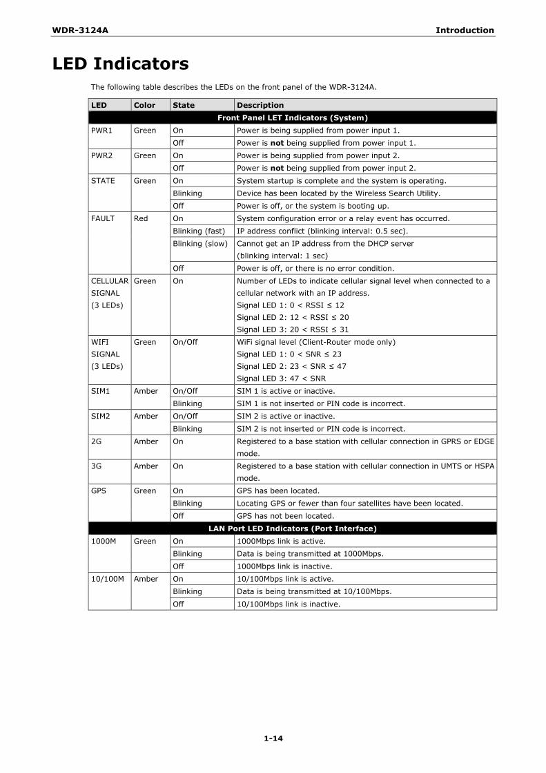
LED Indicators The following table describes the LEDs on the front panel of the WDR-3124A.
LED Color State Description Front Panel LET Indicators (System)
PWR1 Green On Power is being supplied from power input 1.
Off Power is not being supplied from power input 1.
PWR2 Green On Power is being supplied from power input 2.
Off Power is not being supplied from power input 2.
STATE Green On System startup is complete and the system is operating.
Blinking Device has been located by the Wireless Search Utility.
Off Power is off, or the system is booting up.
FAULT Red On System configuration error or a relay event has occurred.
Blinking (fast) IP address conflict (blinking interval: 0.5 sec).
Blinking (slow) Cannot get an IP address from the DHCP server (blinking interval: 1 sec)
Off Power is off, or there is no error condition.
CELLULAR SIGNAL (3 LEDs)
Green On Number of LEDs to indicate cellular signal level when connected to a cellular network with an IP address. Signal LED 1: 0 < RSSI ≤ 12 Signal LED 2: 12 < RSSI ≤ 20 Signal LED 3: 20 < RSSI ≤ 31
WIFI SIGNAL (3 LEDs)
Green On/Off WiFi signal level (Client-Router mode only) Signal LED 1: 0 < SNR ≤ 23 Signal LED 2: 23 < SNR ≤ 47 Signal LED 3: 47 < SNR
SIM1 Amber On/Off SIM 1 is active or inactive.
Blinking SIM 1 is not inserted or PIN code is incorrect.
SIM2 Amber On/Off SIM 2 is active or inactive.
Blinking SIM 2 is not inserted or PIN code is incorrect.
2G Amber On Registered to a base station with cellular connection in GPRS or EDGE mode.
3G Amber On Registered to a base station with cellular connection in UMTS or HSPA mode.
GPS Green On GPS has been located.
Blinking Locating GPS or fewer than four satellites have been located.
Off GPS has not been located.
LAN Port LED Indicators (Port Interface)
1000M Green On 1000Mbps link is active.
Blinking Data is being transmitted at 1000Mbps.
Off 1000Mbps link is inactive.
10/100M Amber On 10/100Mbps link is active.
Blinking Data is being transmitted at 10/100Mbps.
Off 10/100Mbps link is inactive.
WDR-3124A Introduction
1-15
ATTENTION
When the system fails to boot, the LEDs for STATE (Green), FAULT, and WLAN will all light up simultaneously and blink at one-second intervals. This may be due to improper operation or uncontrollable issues, such as an unexpected shutdown while updating the firmware. To recover the firmware, refer to the “Firmware Recovery” section in Appendix B. If the SIM LED is blinking after the WDR-3124A is powered on for several minutes, check the following: • PIN code • SIM installation If the 2G, 3G, and Cellular Signal LEDs are off after the WDR-3124A is powered on for several minutes, check the following: • APN information • Username and password • Antenna connection • Cellular network coverage is available at the current location
Beeper The beeper emits two short beeps when the system is ready.
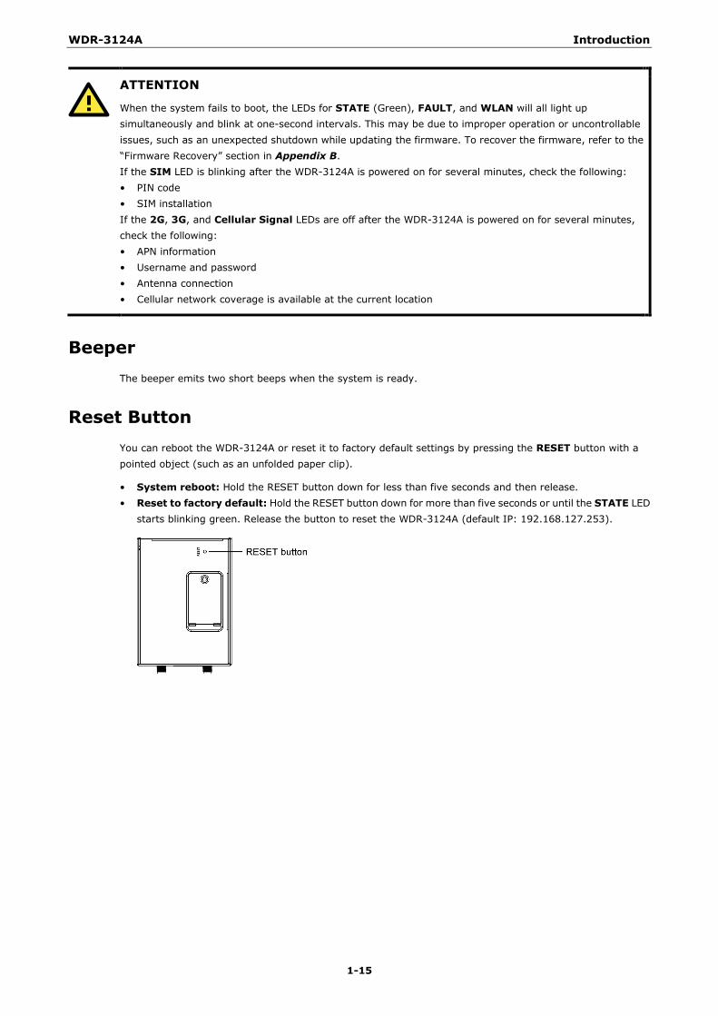
Reset Button You can reboot the WDR-3124A or reset it to factory default settings by pressing the RESET button with a pointed object (such as an unfolded paper clip).
• System reboot: Hold the RESET button down for less than five seconds and then release. • Reset to factory default: Hold the RESET button down for more than five seconds or until the STATE LED
starts blinking green. Release the button to reset the WDR-3124A (default IP: 192.168.127.253).
2 2. Getting Started
When setting up the WDR-3124A for the first time, the first thing you should do is configure its IP address. This chapter describes how to configure the IP address and describes the various configuration options.
The following topics are covered in this chapter:
Static and Dynamic IP Addresses
Factory Default IP Address
Configuration Options
Wireless Search Utility
Web Console
Telnet Console
SSH Console
Serial Console

WDR-3124A Getting Started
2-2
Static and Dynamic IP Addresses Determine whether your WDR-3124A needs to use a static IP address or dynamic IP address (either DHCP or BOOTP application) on the network.
• If your WDR-3124A is used in a static IP environment, you must assign a specific IP address using one of the tools described in this chapter.
• If your WDR-3124A is used in a dynamic IP environment, the IP address will be assigned automatically from over the network. In this case, set the IP configuration mode to DHCP or BOOTP.
ATTENTION
Consult your network administrator on how to reserve a fixed IP address for your WDR-3124A in the MAC-IP mapping table when using a DHCP server or BOOTP server. For most applications, you should assign a fixed IP address for your WDR-3124A.
Factory Default IP Address The default IP address of the WDR-3124A is 192.168.127.254.
Note that IP addresses that begin with “192.168” are referred to as private IP addresses. Devices configured with a private IP address are not directly accessible from a public network. For example, you cannot ping a device with a private IP address from an outside Internet connection.
Configuration Options This section describes the various options you can use to configure the WDR-3124A.
Wireless Search Utility You may configure your WDR-3124A with the bundled Wireless Search Utility on Windows. Please refer to Appendix B, Software Installation/Configuration, for details on how to install and use Wireless Search Utility.
Web Console The web console is the most user-friendly method available to configure the WDR-3124A. With a web browser, you can access the web console. For more information on access and using the web console, refer to the Web Console Configuration chapter.
Telnet Console Depending on how your computer and network are configured, you may find it convenient to use Telnet to configure the IP address of the WDR-3124A.
1. On the computer, open a command window from the start menu and enter the following command:
telnet [IP address]
where [IP address] is the IP address of the WDR-3124A.
2. When prompted, enter 1 for the ansi/vt100 the console terminal type; then, press [Enter].

WDR-3124A Getting Started
2-3
SSH Console When using SSH client (e.g., PuTTY), run the client program (e.g., putty.exe) and then input the WDR-3124A’s IP address, specifying 22 for the SSH connection port.
Serial Console You can access the WDR-3114A through the serial console for configuration. The configuration options and instructions are the same as if you were using the Telnet console.
The following instructions and screenshots show how to access the serial console on the WDR-3124A using PComm Terminal Emulator, which is available free of charge as part of the PComm Lite suite. You may use a different terminal emulator utility, although your actual screens and procedures may vary slightly from the following instructions.
1. Turn off the WDR-3124A.
2. Use an RJ45-to-DB9 serial cable to connect the WDR-3124A’s serial console port to your computer’s RS-232 serial port; then, turn on the WDR-3124A.
3. On the computer, start PComm Terminal Emulator.
4. Click the Open icon (or click Port Manager > Open).
5. The Property window opens. Select the Communication Parameter tab and configure the parameters as shown in the following figure (COM1 port, 115200 for Baudrate, 8 for Data Bits, None for Parity, and 1 for Stop Bits) and click OK.
WDR-3124A Getting Started
2-4
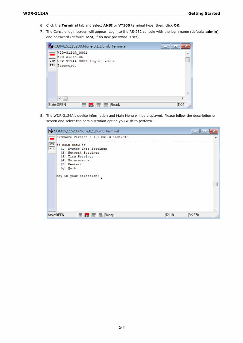
6. Click the Terminal tab and select ANSI or VT100 terminal type; then, click OK.
7. The Console login screen will appear. Log into the RS-232 console with the login name (default: admin) and password (default: root, if no new password is set).
8. The WDR-3124A’s device information and Main Menu will be displayed. Please follow the description on screen and select the administration option you wish to perform.
3 3. Web Console Configuration
The web console is the most user-friendly method available to configure the WDR-3124A. With a standard web browser, you can easily access all settings and options. This chapter describes the configuration options and screens in the web console. The same configuration options are also available through the Telnet and serial consoles.
The following topics are covered in this chapter:
Accessing the Web Console
Overview
Basic Settings
Cellular Settings
Wireless Settings
Advanced Settings
Auto Warning Settings
Status
Maintenance
Save Configuration
Restart
Logout
WDR-3124A Web Console Configuration
3-2
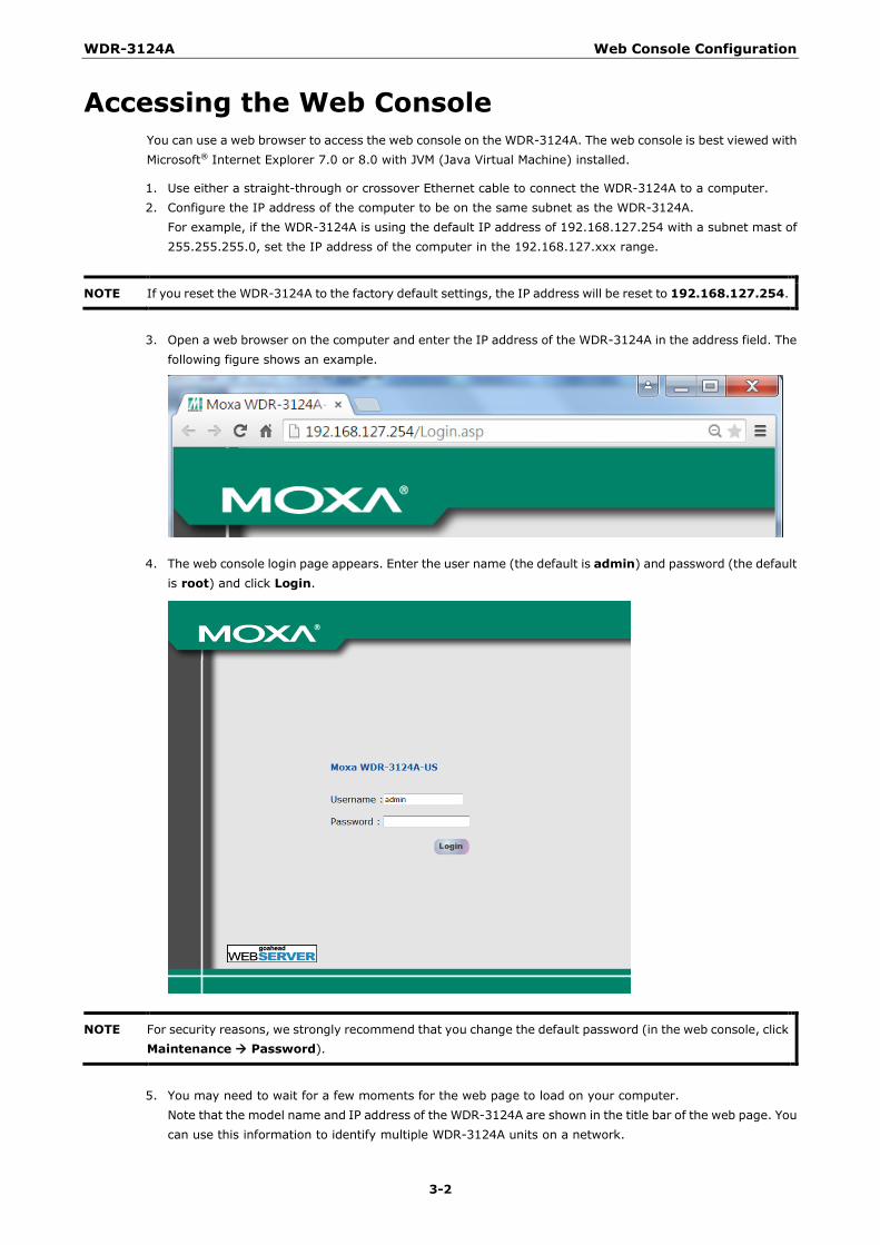
Accessing the Web Console You can use a web browser to access the web console on the WDR-3124A. The web console is best viewed with Microsoft® Internet Explorer 7.0 or 8.0 with JVM (Java Virtual Machine) installed.
1. Use either a straight-through or crossover Ethernet cable to connect the WDR-3124A to a computer. 2. Configure the IP address of the computer to be on the same subnet as the WDR-3124A.
For example, if the WDR-3124A is using the default IP address of 192.168.127.254 with a subnet mast of 255.255.255.0, set the IP address of the computer in the 192.168.127.xxx range.
NOTE If you reset the WDR-3124A to the factory default settings, the IP address will be reset to 192.168.127.254.
3. Open a web browser on the computer and enter the IP address of the WDR-3124A in the address field. The
following figure shows an example.
4. The web console login page appears. Enter the user name (the default is admin) and password (the default is root) and click Login.
NOTE For security reasons, we strongly recommend that you change the default password (in the web console, click Maintenance Password).
5. You may need to wait for a few moments for the web page to load on your computer.
Note that the model name and IP address of the WDR-3124A are shown in the title bar of the web page. You can use this information to identify multiple WDR-3124A units on a network.

WDR-3124A Web Console Configuration
3-3
NOTE After you click Submit to apply changes the web page will refresh and display (Updated) on the page with a blinking reminder on the upper-right corner. The following figure shows an example.
To activate the changes click Restart and then Save and Restart after you change the settings. It may take up to 30 seconds for the WDR-3124A to complete the reboot procedure.
Overview The Overview page displays a summary of the current WDR-3124A status.
To display detailed 802.11 information, click the SSID. The following figure shows an example.
WDR-3124A Web Console Configuration
3-4
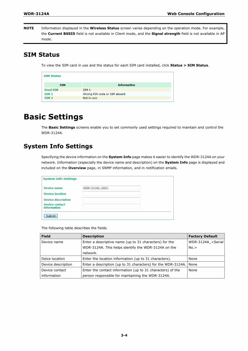
NOTE Information displayed in the Wireless Status screen varies depending on the operation mode. For example, the Current BSSID field is not available in Client mode, and the Signal strength field is not available in AP mode.
SIM Status To view the SIM card in use and the status for each SIM card installed, click Status > SIM Status.
Basic Settings The Basic Settings screens enable you to set commonly used settings required to maintain and control the WDR-3124A.
System Info Settings Specifying the device information on the System Info page makes it easier to identify the WDR-3124A on your network. Information (especially the device name and description) on the System Info page is displayed and included on the Overview page, in SNMP information, and in notification emails.
The following table describes the fields.
Field Description Factory Default Device name Enter a descriptive name (up to 31 characters) for the
WDR-3124A. This helps identify the WDR-3124A on the network.
WDR-3124A_<Serial No.>
Deice location Enter the location information (up to 31 characters). None
Device description Enter a description (up to 31 characters) for the WDR-3124A. None
Device contact information
Enter the contact information (up to 31 characters) of the person responsible for maintaining the WDR-3124A.
None
WDR-3124A Web Console Configuration
3-5
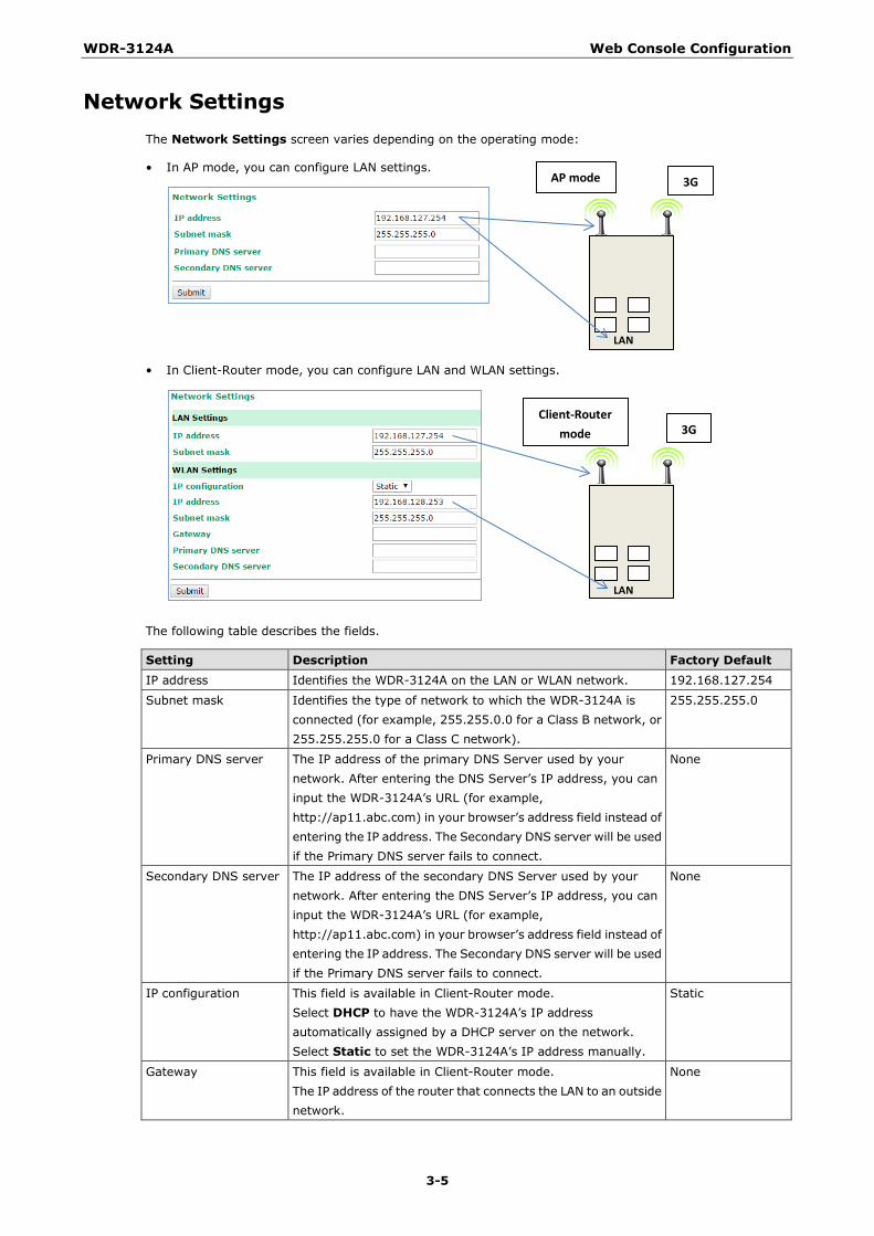
Network Settings The Network Settings screen varies depending on the operating mode:
• In AP mode, you can configure LAN settings.
• In Client-Router mode, you can configure LAN and WLAN settings.
The following table describes the fields.
Setting Description Factory Default IP address Identifies the WDR-3124A on the LAN or WLAN network. 192.168.127.254
Subnet mask Identifies the type of network to which the WDR-3124A is connected (for example, 255.255.0.0 for a Class B network, or 255.255.255.0 for a Class C network).
255.255.255.0
Primary DNS server The IP address of the primary DNS Server used by your network. After entering the DNS Server’s IP address, you can input the WDR-3124A’s URL (for example, http://ap11.abc.com) in your browser’s address field instead of entering the IP address. The Secondary DNS server will be used if the Primary DNS server fails to connect.
None
Secondary DNS server The IP address of the secondary DNS Server used by your network. After entering the DNS Server’s IP address, you can input the WDR-3124A’s URL (for example, http://ap11.abc.com) in your browser’s address field instead of entering the IP address. The Secondary DNS server will be used if the Primary DNS server fails to connect.
None
IP configuration This field is available in Client-Router mode. Select DHCP to have the WDR-3124A’s IP address automatically assigned by a DHCP server on the network. Select Static to set the WDR-3124A’s IP address manually.
Static
Gateway This field is available in Client-Router mode. The IP address of the router that connects the LAN to an outside network.
None
LAN
LAN
3G
3G Client-Router
mode
AP mode
WDR-3124A Web Console Configuration
3-6
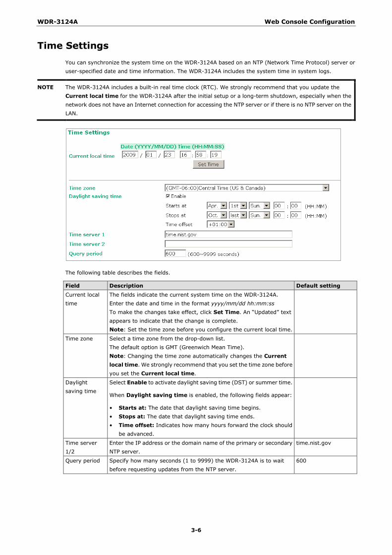
Time Settings You can synchronize the system time on the WDR-3124A based on an NTP (Network Time Protocol) server or user-specified date and time information. The WDR-3124A includes the system time in system logs.
NOTE The WDR-3124A includes a built-in real time clock (RTC). We strongly recommend that you update the Current local time for the WDR-3124A after the initial setup or a long-term shutdown, especially when the network does not have an Internet connection for accessing the NTP server or if there is no NTP server on the LAN.
The following table describes the fields.
Field Description Default setting Current local time
The fields indicate the current system time on the WDR-3124A. Enter the date and time in the format yyyy/mm/dd hh:mm:ss To make the changes take effect, click Set Time. An “Updated” text appears to indicate that the change is complete. Note: Set the time zone before you configure the current local time.
Time zone Select a time zone from the drop-down list. The default option is GMT (Greenwich Mean Time). Note: Changing the time zone automatically changes the Current local time. We strongly recommend that you set the time zone before you set the Current local time.
Daylight saving time
Select Enable to activate daylight saving time (DST) or summer time.
When Daylight saving time is enabled, the following fields appear:
• Starts at: The date that daylight saving time begins. • Stops at: The date that daylight saving time ends. • Time offset: Indicates how many hours forward the clock should
be advanced.
Time server 1/2
Enter the IP address or the domain name of the primary or secondary NTP server.
time.nist.gov
Query period Specify how many seconds (1 to 9999) the WDR-3124A is to wait before requesting updates from the NTP server.
600
WDR-3124A Web Console Configuration
3-7
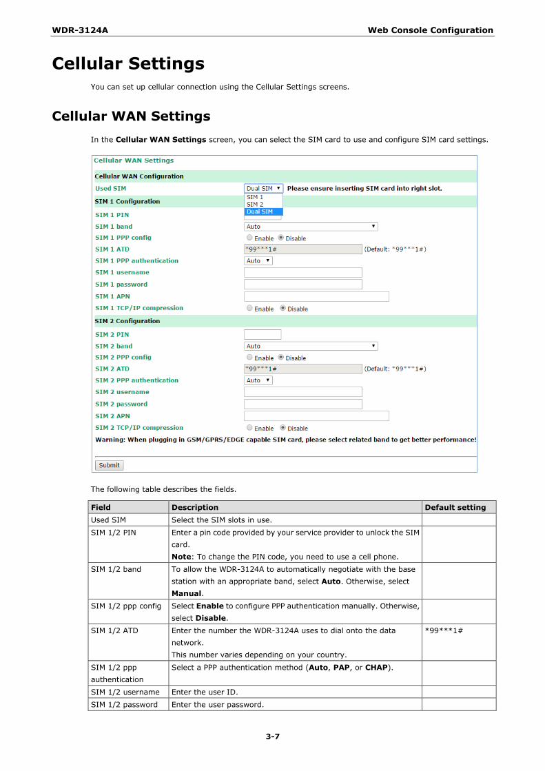
Cellular Settings You can set up cellular connection using the Cellular Settings screens.
Cellular WAN Settings In the Cellular WAN Settings screen, you can select the SIM card to use and configure SIM card settings.
The following table describes the fields.
Field Description Default setting Used SIM Select the SIM slots in use.
SIM 1/2 PIN Enter a pin code provided by your service provider to unlock the SIM card. Note: To change the PIN code, you need to use a cell phone.
SIM 1/2 band To allow the WDR-3124A to automatically negotiate with the base station with an appropriate band, select Auto. Otherwise, select Manual.
SIM 1/2 ppp config Select Enable to configure PPP authentication manually. Otherwise, select Disable.
SIM 1/2 ATD Enter the number the WDR-3124A uses to dial onto the data network. This number varies depending on your country.
*99***1#
SIM 1/2 ppp authentication
Select a PPP authentication method (Auto, PAP, or CHAP).
SIM 1/2 username Enter the user ID.
SIM 1/2 password Enter the user password.
WDR-3124A Web Console Configuration
3-8
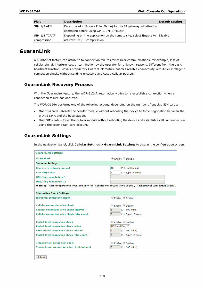
Field Description Default setting SIM 1/2 APN Enter the APN (Access Point Name) for the IP gateway initialization
command before using GPRS/UMTS/HSDPA.
SIM 1/2 TCP/IP compression
Depending on the application on the remote site, select Enable to activate TCP/IP compression.
Disable
GuaranLink A number of factors can attribute to connection failures for cellular communications, for example, loss of cellular signal, interferences, or termination by the operator for unknown reasons. Different from the basic heartbeat function, Moxa’s proprietary GuaranLink feature enables reliable connectivity with 4-tier intelligent connection checks without sending excessive and costly cellular packets.
GuaranLink Recovery Process
With the GuaranLink feature, the WDR-3124A automatically tries to re-establish a connection when a connection failure has occurred.
The WDR-3124A performs one of the following actions, depending on the number of enabled SIM cards:
• One SIM card – Resets the cellular module without rebooting the device to force negotiation between the WDR-3124A and the base station.
• Dual SIM cards – Reset the cellular module without rebooting the device and establish a cellular connection using the second SIM card account.
GuaranLink Settings
In the navigation panel, click Cellular Settings > GuaranLink Settings to display the configuration screen.
WDR-3124A Web Console Configuration
3-9
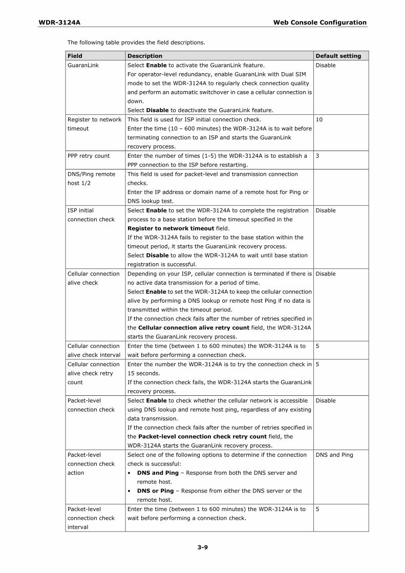
The following table provides the field descriptions.
Field Description Default setting GuaranLink Select Enable to activate the GuaranLink feature.
For operator-level redundancy, enable GuaranLink with Dual SIM mode to set the WDR-3124A to regularly check connection quality and perform an automatic switchover in case a cellular connection is down. Select Disable to deactivate the GuaranLink feature.
Disable
Register to network timeout
This field is used for ISP initial connection check. Enter the time (10 – 600 minutes) the WDR-3124A is to wait before terminating connection to an ISP and starts the GuaranLink recovery process.
10
PPP retry count Enter the number of times (1-5) the WDR-3124A is to establish a PPP connection to the ISP before restarting.
3
DNS/Ping remote host 1/2
This field is used for packet-level and transmission connection checks. Enter the IP address or domain name of a remote host for Ping or DNS lookup test.
ISP initial connection check
Select Enable to set the WDR-3124A to complete the registration process to a base station before the timeout specified in the Register to network timeout field. If the WDR-3124A fails to register to the base station within the timeout period, it starts the GuaranLink recovery process. Select Disable to allow the WDR-3124A to wait until base station registration is successful.
Disable
Cellular connection alive check
Depending on your ISP, cellular connection is terminated if there is no active data transmission for a period of time. Select Enable to set the WDR-3124A to keep the cellular connection alive by performing a DNS lookup or remote host Ping if no data is transmitted within the timeout period. If the connection check fails after the number of retries specified in the Cellular connection alive retry count field, the WDR-3124A starts the GuaranLink recovery process.
Disable
Cellular connection alive check interval
Enter the time (between 1 to 600 minutes) the WDR-3124A is to wait before performing a connection check.
5
Cellular connection alive check retry count
Enter the number the WDR-3124A is to try the connection check in 15 seconds. If the connection check fails, the WDR-3124A starts the GuaranLink recovery process.
5
Packet-level connection check
Select Enable to check whether the cellular network is accessible using DNS lookup and remote host ping, regardless of any existing data transmission. If the connection check fails after the number of retries specified in the Packet-level connection check retry count field, the WDR-3124A starts the GuaranLink recovery process.
Disable
Packet-level connection check action
Select one of the following options to determine if the connection check is successful: • DNS and Ping – Response from both the DNS server and
remote host. • DNS or Ping – Response from either the DNS server or the
remote host.
DNS and Ping
Packet-level connection check interval
Enter the time (between 1 to 600 minutes) the WDR-3124A is to wait before performing a connection check.
5
WDR-3124A Web Console Configuration
3-10
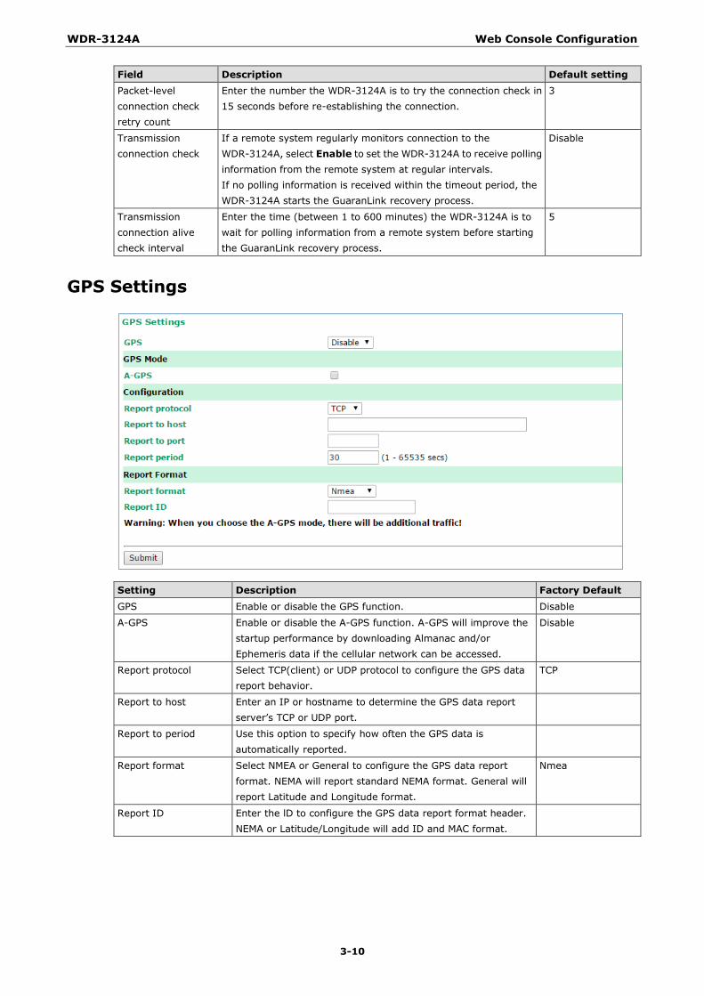
Field Description Default setting Packet-level connection check retry count
Enter the number the WDR-3124A is to try the connection check in 15 seconds before re-establishing the connection.
3
Transmission connection check
If a remote system regularly monitors connection to the WDR-3124A, select Enable to set the WDR-3124A to receive polling information from the remote system at regular intervals. If no polling information is received within the timeout period, the WDR-3124A starts the GuaranLink recovery process.
Disable
Transmission connection alive check interval
Enter the time (between 1 to 600 minutes) the WDR-3124A is to wait for polling information from a remote system before starting the GuaranLink recovery process.
5
GPS Settings
Setting Description Factory Default GPS Enable or disable the GPS function. Disable
A-GPS Enable or disable the A-GPS function. A-GPS will improve the startup performance by downloading Almanac and/or Ephemeris data if the cellular network can be accessed.
Disable
Report protocol Select TCP(client) or UDP protocol to configure the GPS data report behavior.
TCP
Report to host Enter an IP or hostname to determine the GPS data report server’s TCP or UDP port.
Report to period Use this option to specify how often the GPS data is automatically reported.
Report format Select NMEA or General to configure the GPS data report format. NEMA will report standard NEMA format. General will report Latitude and Longitude format.
Nmea
Report ID Enter the lD to configure the GPS data report format header. NEMA or Latitude/Longitude will add ID and MAC format.
WDR-3124A Web Console Configuration
3-11
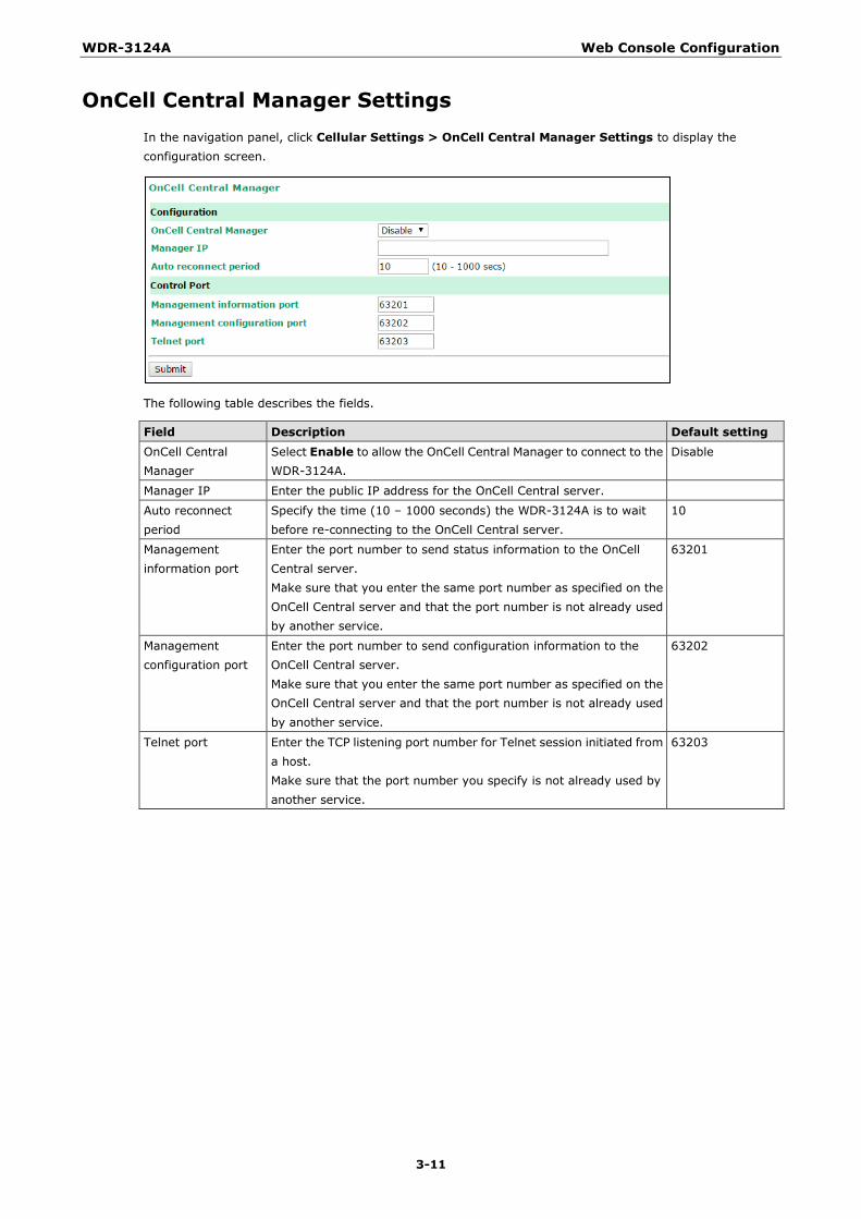
OnCell Central Manager Settings In the navigation panel, click Cellular Settings > OnCell Central Manager Settings to display the configuration screen.
The following table describes the fields.
Field Description Default setting OnCell Central Manager
Select Enable to allow the OnCell Central Manager to connect to the WDR-3124A.
Disable
Manager IP Enter the public IP address for the OnCell Central server.
Auto reconnect period
Specify the time (10 – 1000 seconds) the WDR-3124A is to wait before re-connecting to the OnCell Central server.
10
Management information port
Enter the port number to send status information to the OnCell Central server. Make sure that you enter the same port number as specified on the OnCell Central server and that the port number is not already used by another service.
63201
Management configuration port
Enter the port number to send configuration information to the OnCell Central server. Make sure that you enter the same port number as specified on the OnCell Central server and that the port number is not already used by another service.
63202
Telnet port Enter the TCP listening port number for Telnet session initiated from a host. Make sure that the port number you specify is not already used by another service.
63203
WDR-3124A Web Console Configuration
3-12
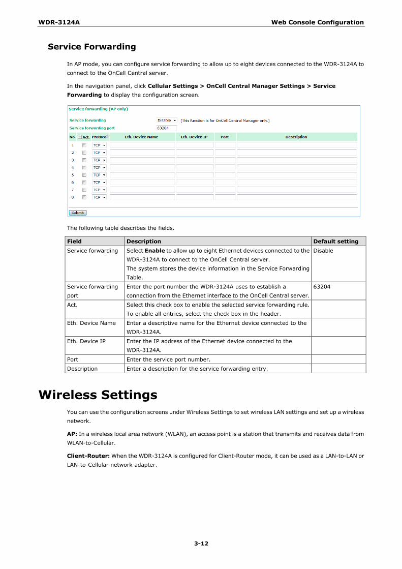
Service Forwarding
In AP mode, you can configure service forwarding to allow up to eight devices connected to the WDR-3124A to connect to the OnCell Central server.
In the navigation panel, click Cellular Settings > OnCell Central Manager Settings > Service Forwarding to display the configuration screen.
The following table describes the fields.
Field Description Default setting Service forwarding Select Enable to allow up to eight Ethernet devices connected to the
WDR-3124A to connect to the OnCell Central server. The system stores the device information in the Service Forwarding Table.
Disable
Service forwarding port
Enter the port number the WDR-3124A uses to establish a connection from the Ethernet interface to the OnCell Central server.
63204
Act. Select this check box to enable the selected service forwarding rule. To enable all entries, select the check box in the header.
Eth. Device Name Enter a descriptive name for the Ethernet device connected to the WDR-3124A.
Eth. Device IP Enter the IP address of the Ethernet device connected to the WDR-3124A.
Port Enter the service port number.
Description Enter a description for the service forwarding entry.
Wireless Settings You can use the configuration screens under Wireless Settings to set wireless LAN settings and set up a wireless network.
AP: In a wireless local area network (WLAN), an access point is a station that transmits and receives data from WLAN-to-Cellular.
Client-Router: When the WDR-3124A is configured for Client-Router mode, it can be used as a LAN-to-LAN or LAN-to-Cellular network adapter.

WDR-3124A Web Console Configuration
3-13
Operation Mode The WDR-3124A supports two operation modes—AP and Client-Router.
The following table provides the field descriptions.
Field Description Default setting Wireless enable This field is available in AP mode.
Select Enable to activate the RF (radio frequency) module. Enable
Operation mode Select AP to set the WDR-3124A to operate as a wireless access point. Select Client-Router to set the WDR-3124A to operate as a wireless client router.
AP
Basic Wireless Settings You can add or edit an SSID in the Basic Setting Selection screen. An SSID is a unique identifier that wireless networking devices use to establish and maintain wireless connectivity. Multiple access points on a network or sub-network can use the same SSIDs.
To configure an SSID, complete the following steps:
1. Click Wireless > WLAN > Basic Wireless Settings.
2. Click Add SSID.
3. Click Save. 4. Click Edit to display the Basic Wireless Settings screen as shown in the following figure.

WDR-3124A Web Console Configuration
3-14
The following table provides the field descriptions.
Field Description Default setting RF type Select an RF option from the drop-down list.
The following lists the options in the 2.4 GHz band: • B – Sets the WDR-3124A to operate in IEEE 802.11b mode. • G – Sets the WDR-3124A to operate in IEEE 802.11g mode. • B/G Mixed – Sets the WDR-3124A to operate in IEEE 802.11b/g
modes. In IEEE 802.11g mode, the WDR-3124A may operate at a lower speed when IEEE 802.11b clients are on the network.
• G/N Mixed – Sets the WDR-3124A to operate in IEEE 802.11g/n modes. In IEEE 802.11n mode, the WDR-3124A may operate at a lower speed when IEEE 802.11g clients are on the network.
• B/G/N Mixed – Sets the WDR-3124A to operate in IEEE 802.11b/g/n modes. In IEEE 802.11g or IEEE 802.11n mode, the WDR-3124A may operate at a lower speed when IEEE 802.11b clients are on the network.
• N Only (2.4 GHz) – Sets the WDR-3124A to operate in 2.4 GHz IEEE 802.11n mode.
The following lists the options in the 5 GHz band: • A – Sets the WDR-3124A to operate in IEEE 802.11a mode. • A/N Mixed – Sets the WDR-3124A to operate in IEEE 802.11a/n
modes. In IEEE 802.11n mode, the WDR-3124A may operate at a lower speed when IEEE 802.11a clients are on the network.
• N Only (5 GHz) – Sets the WDR-3124A to operate in 5 GHz IEEE 802.11n mode.
Note: In legacy mode (802.11a/b/g), the WDR-3124A receives and transmits data only through antenna port A. To protect the connectors and the RF module, all radio ports should be terminated by either an antenna or a terminator. It is strongly recommended that you use a resistive terminator to terminate an unused antenna port.
B/G/N Mixed
Channel (For AP mode)
Select a wireless channel. The number of available channels varies depending on the IEEE 802.11standard.
6 (in B/G/N Mixed mode)
Channel width (For IEEE 802.11n)
Select a channel width for wireless signals. If you are not sure which option to use, select 20/40 MHz.
20 MHz
Channel bonding When you select 20/40 MHz in the Channel width field, the system automatically sets the bonding channel based on the channel setting.
SSID Enter an SSID (up to 31 characters). Make sure that you enter the same SSID on an AP and wireless client for them to communicate with each other.
SSID broadcast Select Enable to broadcast the SSID on the network. Select Disable to hide the SSID. Note: The WDR-3124A-JP (for Japanese frequency bands) only connects SSID-hidden APs for IEEE 802.11a channels, and IEEE 802.11g/n channels 1 to 11. The WDR-3124A-EU (for European frequency bands) only connects SSID-hidden APs for IEEE 802.11b/g/n channels.
Enable
WDR-3124A Web Console Configuration
3-15
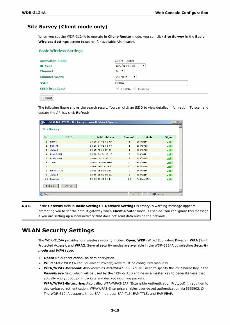
Site Survey (Client mode only)
When you set the WDR-3124A to operate in Client-Router mode, you can click Site Survey in the Basic Wireless Settings screen to search for available APs nearby.
The following figure shows the search result. You can click an SSID to view detailed information. To scan and update the AP list, click Refresh.
NOTE If the Gateway field in Basic Settings > Network Settings is empty, a warning message appears, prompting you to set the default gateway when Client-Router mode is enabled. You can ignore this message if you are setting up a local network that does not send data outside the network.
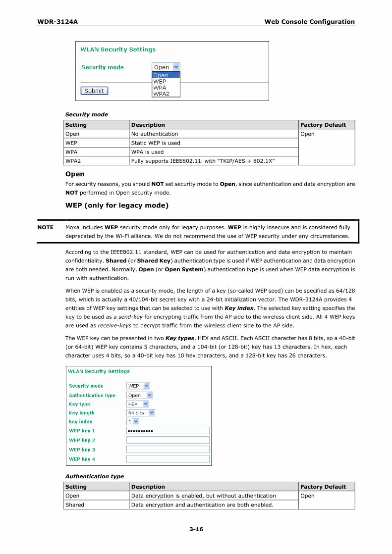
WLAN Security Settings The WDR-3124A provides four wireless security modes: Open, WEP (Wired Equivalent Privacy), WPA (Wi-Fi Protected Access), and WPA2. Several security modes are available in the WDR-3124A by selecting Security mode and WPA type:
• Open: No authentication, no data encryption. • WEP: Static WEP (Wired Equivalent Privacy) keys must be configured manually. • WPA/WPA2-Personal: Also known as WPA/WPA2-PSK. You will need to specify the Pre-Shared Key in the
Passphrase field, which will be used by the TKIP or AES engine as a master key to generate keys that actually encrypt outgoing packets and decrypt incoming packets. WPA/WPA2-Enterprise: Also called WPA/WPA2-EAP (Extensible Authentication Protocol). In addition to device-based authentication, WPA/WPA2-Enterprise enables user-based authentication via IEEE802.1X. The WDR-3124A supports three EAP methods: EAP-TLS, EAP-TTLS, and EAP-PEAP.
WDR-3124A Web Console Configuration
3-16
Security mode
Setting Description Factory Default Open No authentication Open
WEP Static WEP is used
WPA WPA is used
WPA2 Fully supports IEEE802.11i with “TKIP/AES + 802.1X”
Open For security reasons, you should NOT set security mode to Open, since authentication and data encryption are NOT performed in Open security mode.
WEP (only for legacy mode)
NOTE Moxa includes WEP security mode only for legacy purposes. WEP is highly insecure and is considered fully deprecated by the Wi-Fi alliance. We do not recommend the use of WEP security under any circumstances.
According to the IEEE802.11 standard, WEP can be used for authentication and data encryption to maintain confidentiality. Shared (or Shared Key) authentication type is used if WEP authentication and data encryption are both needed. Normally, Open (or Open System) authentication type is used when WEP data encryption is run with authentication.
When WEP is enabled as a security mode, the length of a key (so-called WEP seed) can be specified as 64/128 bits, which is actually a 40/104-bit secret key with a 24-bit initialization vector. The WDR-3124A provides 4 entities of WEP key settings that can be selected to use with Key index. The selected key setting specifies the key to be used as a send-key for encrypting traffic from the AP side to the wireless client side. All 4 WEP keys are used as receive-keys to decrypt traffic from the wireless client side to the AP side.
The WEP key can be presented in two Key types, HEX and ASCII. Each ASCII character has 8 bits, so a 40-bit (or 64-bit) WEP key contains 5 characters, and a 104-bit (or 128-bit) key has 13 characters. In hex, each character uses 4 bits, so a 40-bit key has 10 hex characters, and a 128-bit key has 26 characters.
Authentication type
Setting Description Factory Default Open Data encryption is enabled, but without authentication Open
Shared Data encryption and authentication are both enabled.
WDR-3124A Web Console Configuration
3-17
Key type
Setting Description Factory Default HEX Specifies WEP keys in hex-decimal number form HEX
ASCII Specifies WEP keys in ASCII form
Key length
Setting Description Factory Default 64 bits Uses 40-bit secret keys with 24-bit initialization vector 64 bits
128 bits Uses 104-bit secret key with 24-bit initialization vector
Key index
Setting Description Factory Default 1-4 Specifies which WEP key is used Open
WEP key 1-4
Setting Description Factory Default ASCII type: 64 bits: 5 chars 128 bits: 13chars HEX type: 64 bits: 10 hex chars 128 bits: 26 hex chars
A string that can be used as a WEP seed for the RC4 encryption engine.
None
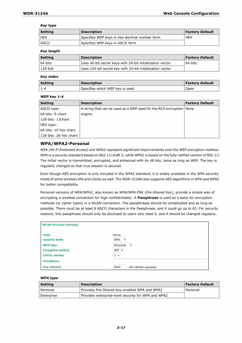
WPA/WPA2-Personal WPA (Wi-Fi Protected Access) and WPA2 represent significant improvements over the WEP encryption method. WPA is a security standard based on 802.11i draft 3, while WPA2 is based on the fully ratified version of 802.11i. The initial vector is transmitted, encrypted, and enhanced with its 48 bits, twice as long as WEP. The key is regularly changed so that true session is secured.
Even though AES encryption is only included in the WPA2 standard, it is widely available in the WPA security mode of some wireless APs and clients as well. The WDR-3124A also supports AES algorithms in WPA and WPA2 for better compatibility.
Personal versions of WPA/WPA2, also known as WPA/WPA-PSK (Pre-Shared Key), provide a simple way of encrypting a wireless connection for high confidentiality. A Passphrase is used as a basis for encryption methods (or cipher types) in a WLAN connection. The passphrases should be complicated and as long as possible. There must be at least 8 ASCII characters in the Passphrase, and it could go up to 63. For security reasons, this passphrase should only be disclosed to users who need it, and it should be changed regularly.
WPA type
Setting Description Factory Default Personal Provides Pre-Shared Key-enabled WPA and WPA2 Personal
Enterprise Provides enterprise-level security for WPA and WPA2
WDR-3124A Web Console Configuration
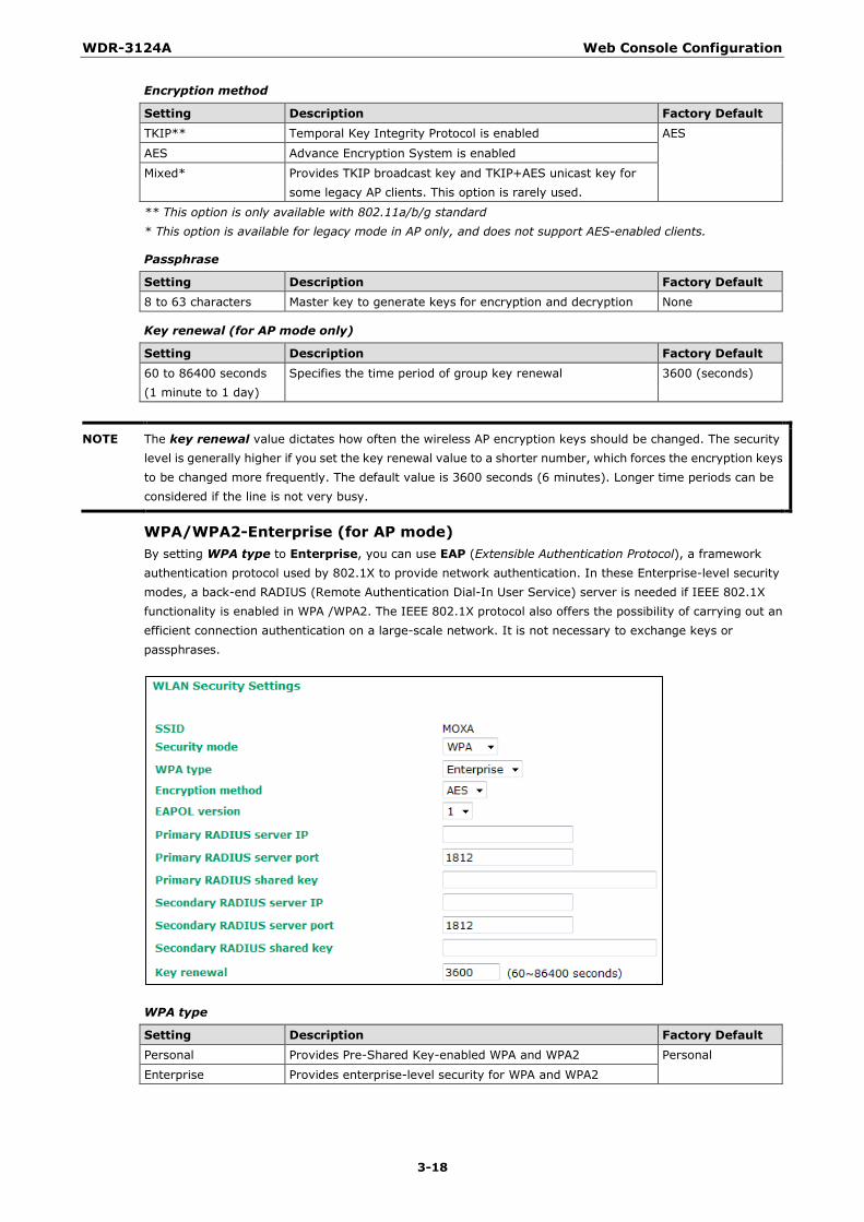
3-18
Encryption method
Setting Description Factory Default TKIP** Temporal Key Integrity Protocol is enabled AES
AES Advance Encryption System is enabled
Mixed* Provides TKIP broadcast key and TKIP+AES unicast key for some legacy AP clients. This option is rarely used.
** This option is only available with 802.11a/b/g standard * This option is available for legacy mode in AP only, and does not support AES-enabled clients.
Passphrase
Setting Description Factory Default 8 to 63 characters Master key to generate keys for encryption and decryption None
Key renewal (for AP mode only)
Setting Description Factory Default 60 to 86400 seconds (1 minute to 1 day)
Specifies the time period of group key renewal 3600 (seconds)
NOTE The key renewal value dictates how often the wireless AP encryption keys should be changed. The security level is generally higher if you set the key renewal value to a shorter number, which forces the encryption keys to be changed more frequently. The default value is 3600 seconds (6 minutes). Longer time periods can be considered if the line is not very busy.
WPA/WPA2-Enterprise (for AP mode) By setting WPA type to Enterprise, you can use EAP (Extensible Authentication Protocol), a framework authentication protocol used by 802.1X to provide network authentication. In these Enterprise-level security modes, a back-end RADIUS (Remote Authentication Dial-In User Service) server is needed if IEEE 802.1X functionality is enabled in WPA /WPA2. The IEEE 802.1X protocol also offers the possibility of carrying out an efficient connection authentication on a large-scale network. It is not necessary to exchange keys or passphrases.
WPA type
Setting Description Factory Default Personal Provides Pre-Shared Key-enabled WPA and WPA2 Personal
Enterprise Provides enterprise-level security for WPA and WPA2
WDR-3124A Web Console Configuration
3-19
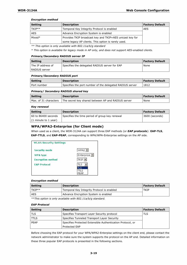
Encryption method
Setting Description Factory Default TKIP** Temporal Key Integrity Protocol is enabled AES
AES Advance Encryption System is enabled
Mixed* Provides TKIP broadcast key and TKIP+AES unicast key for some legacy AP clients. This option is rarely used.
** This option is only available with 802.11a/b/g standard * This option is available for legacy mode in AP only, and does not support AES-enabled clients.
Primary/Secondary RADIUS server IP
Setting Description Factory Default The IP address of RADIUS server
Specifies the delegated RADIUS server for EAP None
Primary/Secondary RADIUS port
Setting Description Factory Default Port number Specifies the port number of the delegated RADIUS server 1812
Primary/ Secondary RADIUS shared key
Setting Description Factory Default Max. of 31 characters The secret key shared between AP and RADIUS server None
Key renewal
Setting Description Factory Default 60 to 86400 seconds (1 minute to 1 year)
Specifies the time period of group key renewal 3600 (seconds)
WPA/WPA2-Enterprise (for Client mode) When used as a client, the WDR-3124A can support three EAP methods (or EAP protocols): EAP-TLS, EAP-TTLS, and EAP-PEAP, corresponding to WPA/WPA-Enterprise settings on the AP side.
Encryption method
Setting Description Factory Default TKIP** Temporal Key Integrity Protocol is enabled TKIP
AES Advance Encryption System is enabled
**This option is only available with 802.11a/b/g standard.
EAP Protocol
Setting Description Factory Default TLS Specifies Transport Layer Security protocol TLS
TTLS Specifies Tunneled Transport Layer Security
PEAP Specifies Protected Extensible Authentication Protocol, or Protected EAP
Before choosing the EAP protocol for your WPA/WPA2-Enterpise settings on the client end, please contact the network administrator to make sure the system supports the protocol on the AP end. Detailed information on these three popular EAP protocols is presented in the following sections.
WDR-3124A Web Console Configuration
3-20
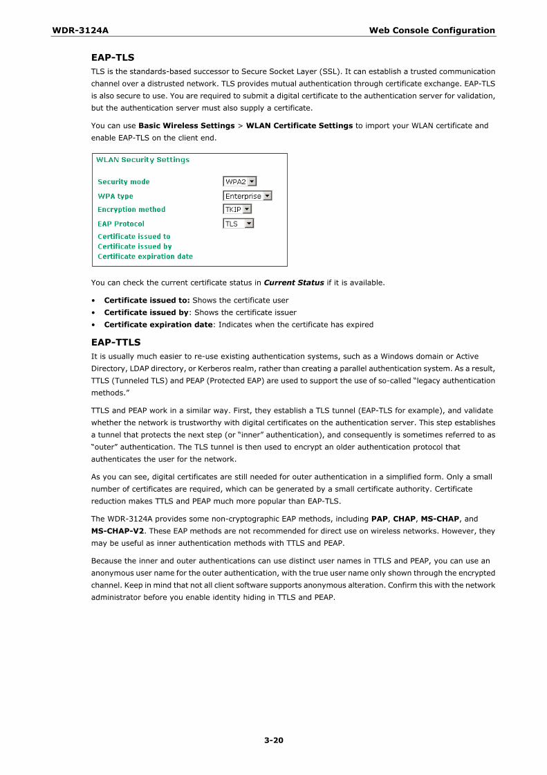
EAP-TLS TLS is the standards-based successor to Secure Socket Layer (SSL). It can establish a trusted communication channel over a distrusted network. TLS provides mutual authentication through certificate exchange. EAP-TLS is also secure to use. You are required to submit a digital certificate to the authentication server for validation, but the authentication server must also supply a certificate.
You can use Basic Wireless Settings > WLAN Certificate Settings to import your WLAN certificate and enable EAP-TLS on the client end.
You can check the current certificate status in Current Status if it is available.
• Certificate issued to: Shows the certificate user • Certificate issued by: Shows the certificate issuer • Certificate expiration date: Indicates when the certificate has expired
EAP-TTLS It is usually much easier to re-use existing authentication systems, such as a Windows domain or Active Directory, LDAP directory, or Kerberos realm, rather than creating a parallel authentication system. As a result, TTLS (Tunneled TLS) and PEAP (Protected EAP) are used to support the use of so-called “legacy authentication methods.”
TTLS and PEAP work in a similar way. First, they establish a TLS tunnel (EAP-TLS for example), and validate whether the network is trustworthy with digital certificates on the authentication server. This step establishes a tunnel that protects the next step (or “inner” authentication), and consequently is sometimes referred to as “outer” authentication. The TLS tunnel is then used to encrypt an older authentication protocol that authenticates the user for the network.
As you can see, digital certificates are still needed for outer authentication in a simplified form. Only a small number of certificates are required, which can be generated by a small certificate authority. Certificate reduction makes TTLS and PEAP much more popular than EAP-TLS.
The WDR-3124A provides some non-cryptographic EAP methods, including PAP, CHAP, MS-CHAP, and MS-CHAP-V2. These EAP methods are not recommended for direct use on wireless networks. However, they may be useful as inner authentication methods with TTLS and PEAP.
Because the inner and outer authentications can use distinct user names in TTLS and PEAP, you can use an anonymous user name for the outer authentication, with the true user name only shown through the encrypted channel. Keep in mind that not all client software supports anonymous alteration. Confirm this with the network administrator before you enable identity hiding in TTLS and PEAP.
WDR-3124A Web Console Configuration
3-21
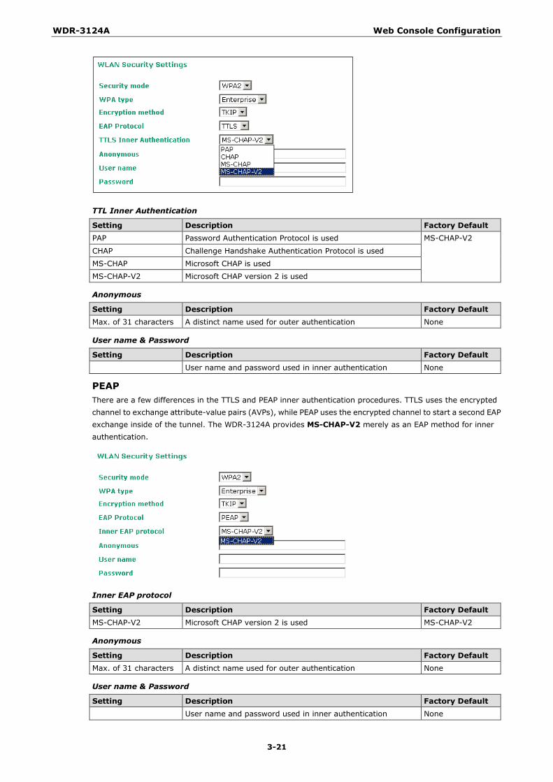
TTL Inner Authentication
Setting Description Factory Default PAP Password Authentication Protocol is used MS-CHAP-V2
CHAP Challenge Handshake Authentication Protocol is used
MS-CHAP Microsoft CHAP is used
MS-CHAP-V2 Microsoft CHAP version 2 is used
Anonymous
Setting Description Factory Default Max. of 31 characters A distinct name used for outer authentication None
User name & Password
Setting Description Factory Default User name and password used in inner authentication None
PEAP There are a few differences in the TTLS and PEAP inner authentication procedures. TTLS uses the encrypted channel to exchange attribute-value pairs (AVPs), while PEAP uses the encrypted channel to start a second EAP exchange inside of the tunnel. The WDR-3124A provides MS-CHAP-V2 merely as an EAP method for inner authentication.
Inner EAP protocol
Setting Description Factory Default MS-CHAP-V2 Microsoft CHAP version 2 is used MS-CHAP-V2
Anonymous
Setting Description Factory Default Max. of 31 characters A distinct name used for outer authentication None
User name & Password
Setting Description Factory Default User name and password used in inner authentication None
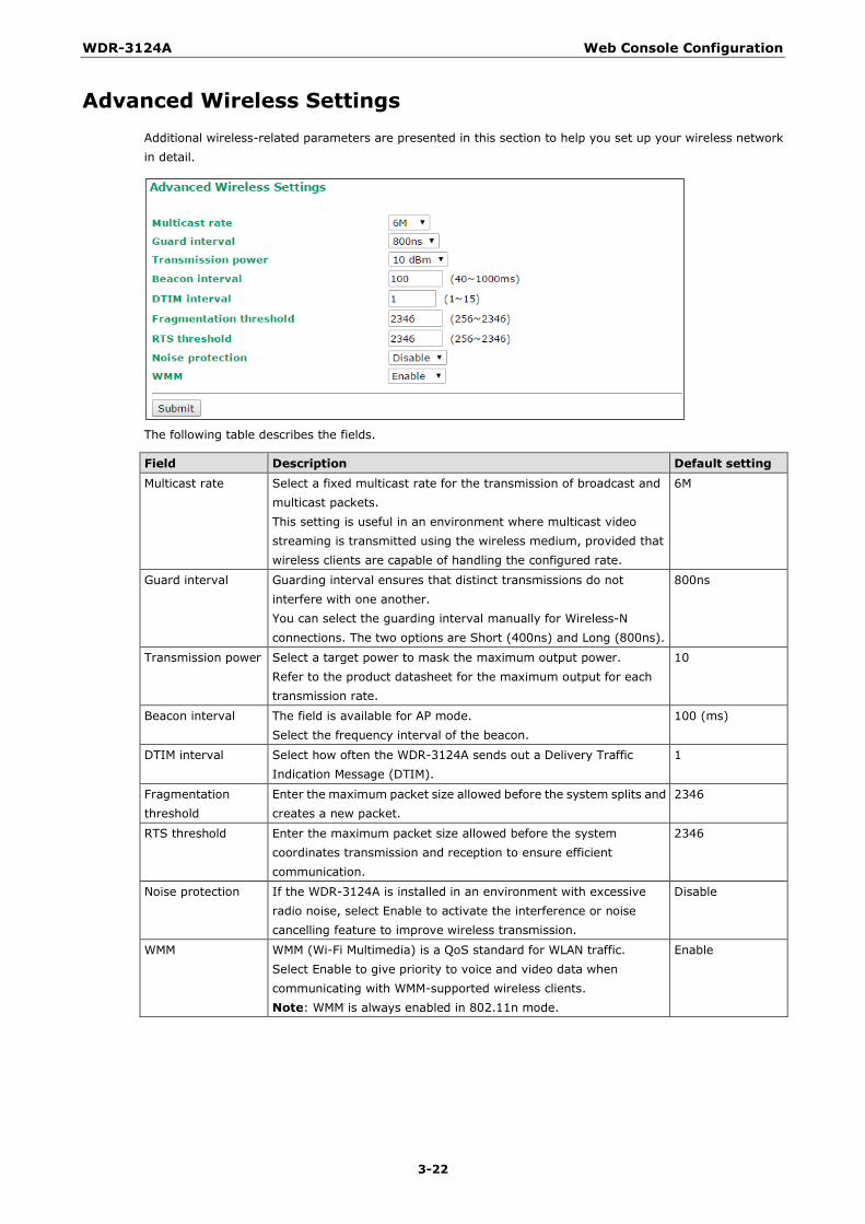
WDR-3124A Web Console Configuration
3-22
Advanced Wireless Settings Additional wireless-related parameters are presented in this section to help you set up your wireless network in detail.
The following table describes the fields.
Field Description Default setting Multicast rate Select a fixed multicast rate for the transmission of broadcast and
multicast packets. This setting is useful in an environment where multicast video streaming is transmitted using the wireless medium, provided that wireless clients are capable of handling the configured rate.
6M
Guard interval Guarding interval ensures that distinct transmissions do not interfere with one another. You can select the guarding interval manually for Wireless-N connections. The two options are Short (400ns) and Long (800ns).
800ns
Transmission power Select a target power to mask the maximum output power. Refer to the product datasheet for the maximum output for each transmission rate.
10
Beacon interval The field is available for AP mode. Select the frequency interval of the beacon.
100 (ms)
DTIM interval Select how often the WDR-3124A sends out a Delivery Traffic Indication Message (DTIM).
1
Fragmentation threshold
Enter the maximum packet size allowed before the system splits and creates a new packet.
2346
RTS threshold Enter the maximum packet size allowed before the system coordinates transmission and reception to ensure efficient communication.
2346
Noise protection If the WDR-3124A is installed in an environment with excessive radio noise, select Enable to activate the interference or noise cancelling feature to improve wireless transmission.
Disable
WMM WMM (Wi-Fi Multimedia) is a QoS standard for WLAN traffic. Select Enable to give priority to voice and video data when communicating with WMM-supported wireless clients. Note: WMM is always enabled in 802.11n mode.
Enable

WDR-3124A Web Console Configuration
3-23
WLAN Certification Settings (for EAP-TLS in Client mode only) When EAP-TLS is used, a WLAN Certificate will be required at the client end to support WPA/WPA2-Enterprise. The WDR-3124A can support the PKCS #12, also known as Personal Information Exchange Syntax Standard, certificate formats that define file formats commonly used to store private keys with accompanying public key certificates, protected with a password-based symmetric key.
Current Status displays information for the current WLAN certificate, which has been imported into the WDR-3124A. Nothing will be shown if a certificate is not available.
Certificate issued to: Shows the certificate user
Certificate issued by: Shows the certificate issuer
Certificate expiration date: Indicates when the certificate has expired
You can import a new WLAN certificate in Import WLAN Certificate by following these steps, in order:
1. Input the corresponding password (or key) in the Certificate private password field and then click Submit to set the password.
2. The password will be displayed in the Certificate private password field. Click on the Browse button in Select certificate/key file and select the certificate file.
3. Click Upload Certificate File to import the certificate file. If the import succeeds, you can see the information uploaded in Current Certificate. If it fails, you may need to return to step 1 to set the password correctly and then import the certificate file again.
NOTE The WLAN certificate will remain after the WDR-3124A reboots. Even though it is expired, it can still be seen on the Current Certificate.
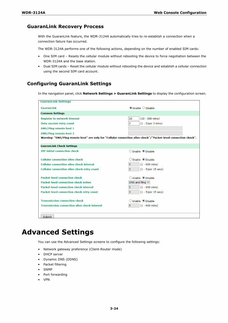
WDR-3124A Web Console Configuration
3-24
GuaranLink Recovery Process
With the GuaranLink feature, the WDR-3124A automatically tries to re-establish a connection when a connection failure has occurred.
The WDR-3124A performs one of the following actions, depending on the number of enabled SIM cards:
• One SIM card – Resets the cellular module without rebooting the device to force negotiation between the WDR-3124A and the base station.
• Dual SIM cards – Reset the cellular module without rebooting the device and establish a cellular connection using the second SIM card account.
Configuring GuaranLink Settings
In the navigation panel, click Network Settings > GuaranLink Settings to display the configuration screen.
Advanced Settings You can use the Advanced Settings screens to configure the following settings:
• Network gateway preference (Client-Router mode) • DHCP server • Dynamic DNS (DDNS) • Packet filtering • SNMP • Port forwarding • VPN
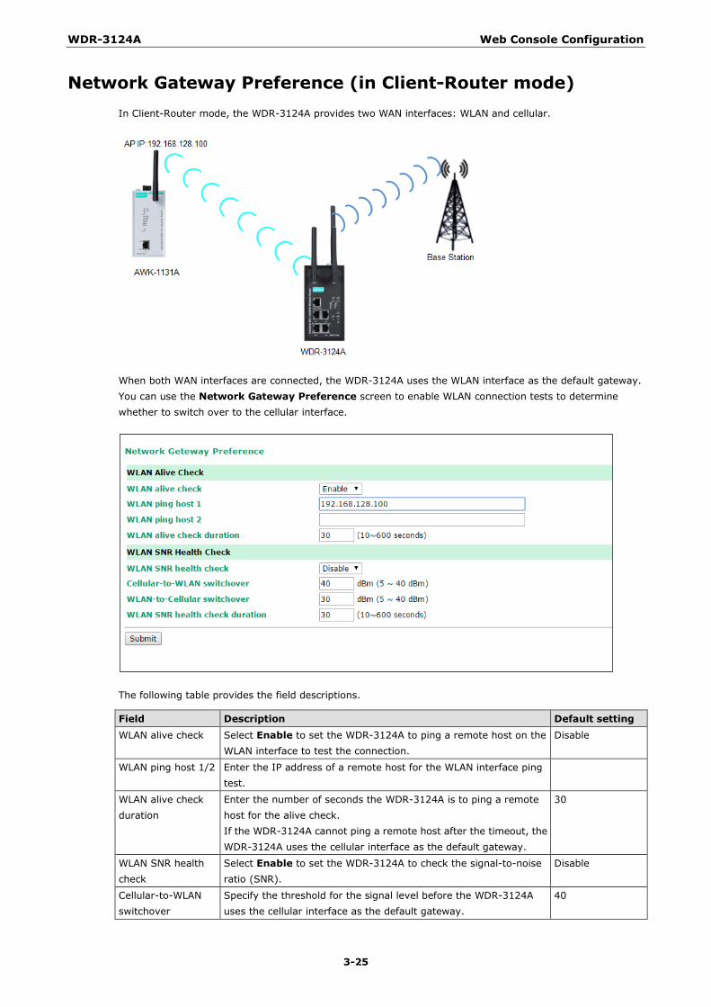
WDR-3124A Web Console Configuration
3-25
Network Gateway Preference (in Client-Router mode) In Client-Router mode, the WDR-3124A provides two WAN interfaces: WLAN and cellular.
When both WAN interfaces are connected, the WDR-3124A uses the WLAN interface as the default gateway. You can use the Network Gateway Preference screen to enable WLAN connection tests to determine whether to switch over to the cellular interface.
The following table provides the field descriptions.
Field Description Default setting WLAN alive check Select Enable to set the WDR-3124A to ping a remote host on the
WLAN interface to test the connection. Disable
WLAN ping host 1/2 Enter the IP address of a remote host for the WLAN interface ping test.
WLAN alive check duration
Enter the number of seconds the WDR-3124A is to ping a remote host for the alive check. If the WDR-3124A cannot ping a remote host after the timeout, the WDR-3124A uses the cellular interface as the default gateway.
30
WLAN SNR health check
Select Enable to set the WDR-3124A to check the signal-to-noise ratio (SNR).
Disable
Cellular-to-WLAN switchover
Specify the threshold for the signal level before the WDR-3124A uses the cellular interface as the default gateway.
40
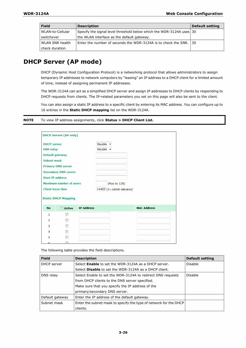
WDR-3124A Web Console Configuration
3-26
Field Description Default setting WLAN-to-Cellular switchover
Specify the signal level threshold below which the WDR-3124A uses the WLAN interface as the default gateway.
30
WLAN SNR health check duration
Enter the number of seconds the WDR-3124A is to check the SNR. 30
DHCP Server (AP mode) DHCP (Dynamic Host Configuration Protocol) is a networking protocol that allows administrators to assign temporary IP addresses to network computers by “leasing” an IP address to a DHCP client for a limited amount of time, instead of assigning permanent IP addresses.
The WDR-3124A can act as a simplified DHCP server and assign IP addresses to DHCP clients by responding to DHCP requests from clients. The IP-related parameters you set on this page will also be sent to the client.
You can also assign a static IP address to a specific client by entering its MAC address. You can configure up to 16 entries in the Static DHCP mapping list on the WDR-3124A.
NOTE To view IP address assignments, click Status > DHCP Client List.
The following table provides the field descriptions.
Field Description Default setting DHCP server Select Enable to set the WDR-3124A as a DHCP server.
Select Disable to set the WDR-3124A as a DHCP client. Disable
DNS relay Select Enable to set the WDR-3124A to redirect DNS requests from DHCP clients to the DNS server specified. Make sure that you specify the IP address of the primary/secondary DNS server.
Disable
Default gateway Enter the IP address of the default gateway.
Subnet mask Enter the subnet mask to specify the type of network for the DHCP clients.
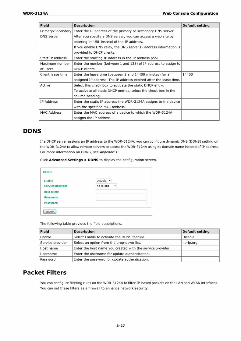
WDR-3124A Web Console Configuration
3-27
Field Description Default setting Primary/Secondary DNS server
Enter the IP address of the primary or secondary DNS server. After you specify a DNS server, you can access a web site by entering its URL instead of the IP address. If you enable DNS relay, the DNS server IP address information is provided to DHCP clients.
Start IP address Enter the starting IP address in the IP address pool.
Maximum number of users
Enter the number (between 1 and 128) of IP address to assign to DHCP clients.
Client lease time Enter the lease time (between 2 and 14400 minutes) for an assigned IP address. The IP address expired after the lease time.
14400
Active Select this check box to activate the static DHCP entry. To activate all static DHCP entries, select the check box in the column heading.
IP Address Enter the static IP address the WDR-3124A assigns to the device with the specified MAC address.
MAC Address Enter the MAC address of a device to which the WDR-3124A assigns the IP address.
DDNS If a DHCP server assigns an IP address to the WDR-3124A, you can configure dynamic DNS (DDNS) setting on the WDR-3124A to allow remote servers to access the WDR-3124A using its domain name instead of IP address. For more information on DDNS, see Appendix C.
Click Advanced Settings > DDNS to display the configuration screen.
The following table provides the field descriptions.
Field Description Default setting Enable Select Enable to activate the DDNS feature. Disable
Service provider Select an option from the drop-down list. no-ip.org
Host name Enter the host name you created with the service provider.
Username Enter the username for update authentication.
Password Enter the password for update authentication.
Packet Filters You can configure filtering rules on the WDR-3124A to filter IP-based packets on the LAN and WLAN interfaces. You can set these filters as a firewall to enhance network security.
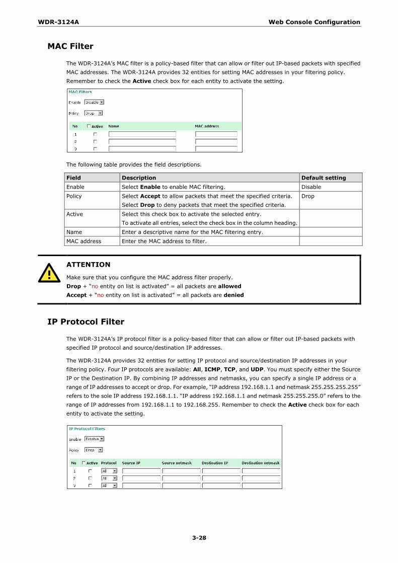
WDR-3124A Web Console Configuration
3-28
MAC Filter
The WDR-3124A’s MAC filter is a policy-based filter that can allow or filter out IP-based packets with specified MAC addresses. The WDR-3124A provides 32 entities for setting MAC addresses in your filtering policy. Remember to check the Active check box for each entity to activate the setting.
The following table provides the field descriptions.
Field Description Default setting Enable Select Enable to enable MAC filtering. Disable
Policy Select Accept to allow packets that meet the specified criteria. Select Drop to deny packets that meet the specified criteria.
Drop
Active Select this check box to activate the selected entry. To activate all entries, select the check box in the column heading.
Name Enter a descriptive name for the MAC filtering entry.
MAC address Enter the MAC address to filter.
ATTENTION
Make sure that you configure the MAC address filter properly. Drop + “no entity on list is activated” = all packets are allowed Accept + “no entity on list is activated” = all packets are denied
IP Protocol Filter
The WDR-3124A’s IP protocol filter is a policy-based filter that can allow or filter out IP-based packets with specified IP protocol and source/destination IP addresses.
The WDR-3124A provides 32 entities for setting IP protocol and source/destination IP addresses in your filtering policy. Four IP protocols are available: All, ICMP, TCP, and UDP. You must specify either the Source IP or the Destination IP. By combining IP addresses and netmasks, you can specify a single IP address or a range of IP addresses to accept or drop. For example, “IP address 192.168.1.1 and netmask 255.255.255.255” refers to the sole IP address 192.168.1.1. “IP address 192.168.1.1 and netmask 255.255.255.0” refers to the range of IP addresses from 192.168.1.1 to 192.168.255. Remember to check the Active check box for each entity to activate the setting.
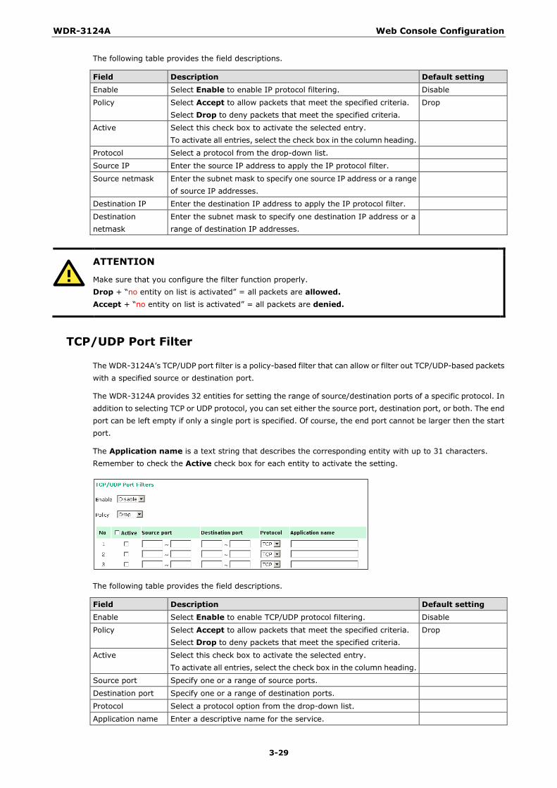
WDR-3124A Web Console Configuration
3-29
The following table provides the field descriptions.
Field Description Default setting Enable Select Enable to enable IP protocol filtering. Disable
Policy Select Accept to allow packets that meet the specified criteria. Select Drop to deny packets that meet the specified criteria.
Drop
Active Select this check box to activate the selected entry. To activate all entries, select the check box in the column heading.
Protocol Select a protocol from the drop-down list.
Source IP Enter the source IP address to apply the IP protocol filter.
Source netmask Enter the subnet mask to specify one source IP address or a range of source IP addresses.
Destination IP Enter the destination IP address to apply the IP protocol filter.
Destination netmask
Enter the subnet mask to specify one destination IP address or a range of destination IP addresses.
ATTENTION
Make sure that you configure the filter function properly. Drop + “no entity on list is activated” = all packets are allowed. Accept + “no entity on list is activated” = all packets are denied.
TCP/UDP Port Filter
The WDR-3124A’s TCP/UDP port filter is a policy-based filter that can allow or filter out TCP/UDP-based packets with a specified source or destination port.
The WDR-3124A provides 32 entities for setting the range of source/destination ports of a specific protocol. In addition to selecting TCP or UDP protocol, you can set either the source port, destination port, or both. The end port can be left empty if only a single port is specified. Of course, the end port cannot be larger then the start port.
The Application name is a text string that describes the corresponding entity with up to 31 characters. Remember to check the Active check box for each entity to activate the setting.
The following table provides the field descriptions.
Field Description Default setting Enable Select Enable to enable TCP/UDP protocol filtering. Disable
Policy Select Accept to allow packets that meet the specified criteria. Select Drop to deny packets that meet the specified criteria.
Drop
Active Select this check box to activate the selected entry. To activate all entries, select the check box in the column heading.
Source port Specify one or a range of source ports.
Destination port Specify one or a range of destination ports.
Protocol Select a protocol option from the drop-down list.
Application name Enter a descriptive name for the service.
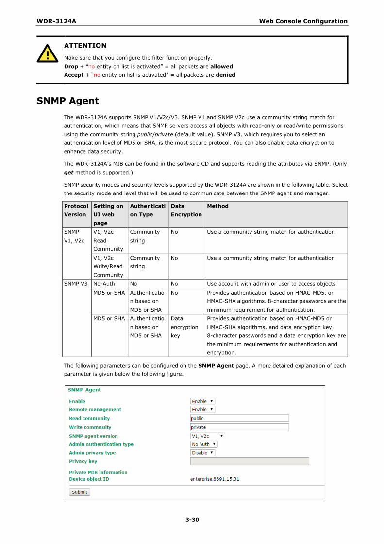
WDR-3124A Web Console Configuration
3-30
ATTENTION
Make sure that you configure the filter function properly. Drop + “no entity on list is activated” = all packets are allowed Accept + “no entity on list is activated” = all packets are denied
SNMP Agent The WDR-3124A supports SNMP V1/V2c/V3. SNMP V1 and SNMP V2c use a community string match for authentication, which means that SNMP servers access all objects with read-only or read/write permissions using the community string public/private (default value). SNMP V3, which requires you to select an authentication level of MD5 or SHA, is the most secure protocol. You can also enable data encryption to enhance data security.
The WDR-3124A’s MIB can be found in the software CD and supports reading the attributes via SNMP. (Only get method is supported.)
SNMP security modes and security levels supported by the WDR-3124A are shown in the following table. Select the security mode and level that will be used to communicate between the SNMP agent and manager.
Protocol Version
Setting on UI web page
Authentication Type
Data Encryption
Method
SNMP V1, V2c
V1, V2c Read Community
Community string
No Use a community string match for authentication
V1, V2c Write/Read Community
Community string
No Use a community string match for authentication
SNMP V3 No-Auth No No Use account with admin or user to access objects
MD5 or SHA Authentication based on MD5 or SHA
No Provides authentication based on HMAC-MD5, or HMAC-SHA algorithms. 8-character passwords are the minimum requirement for authentication.
MD5 or SHA Authentication based on MD5 or SHA
Data encryption key
Provides authentication based on HMAC-MD5 or HMAC-SHA algorithms, and data encryption key. 8-character passwords and a data encryption key are the minimum requirements for authentication and encryption.
The following parameters can be configured on the SNMP Agent page. A more detailed explanation of each parameter is given below the following figure.
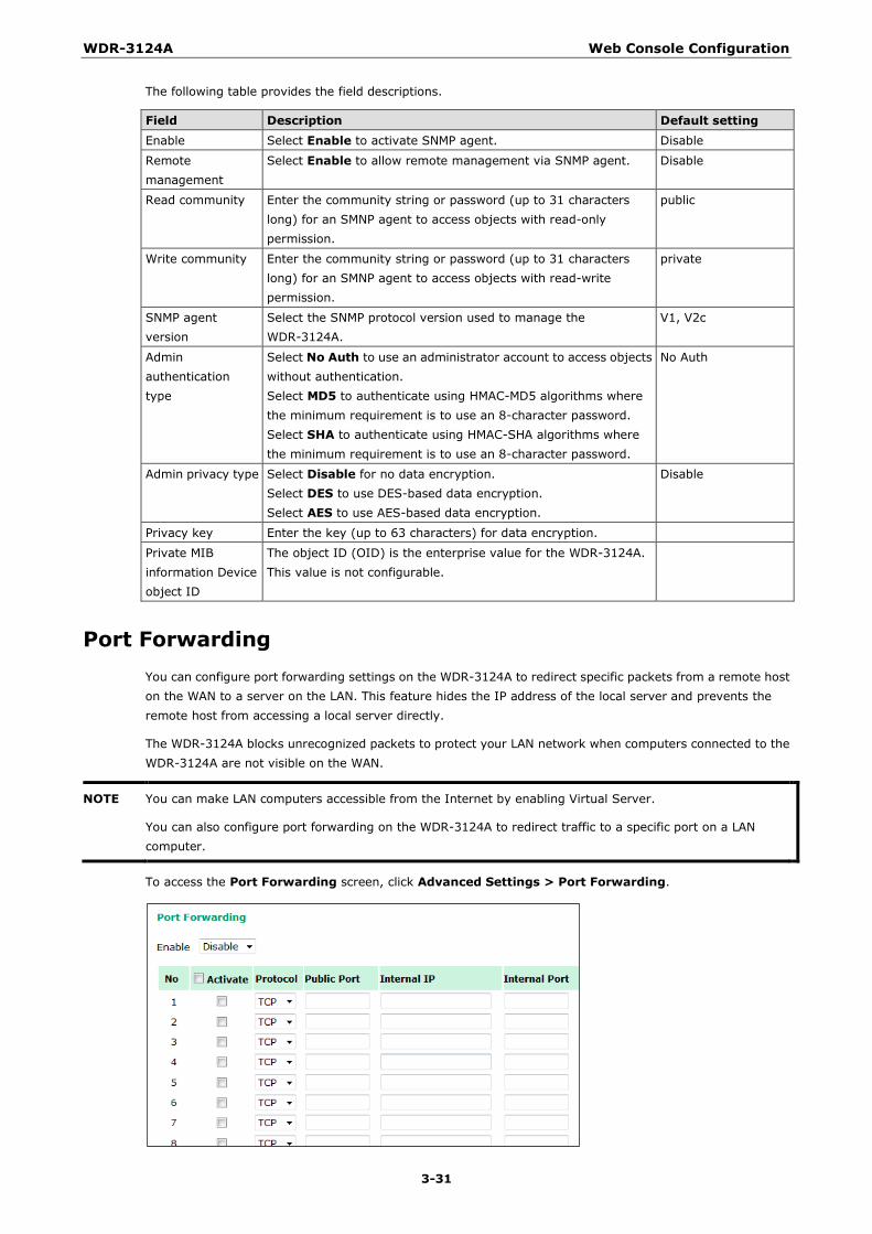
WDR-3124A Web Console Configuration
3-31
The following table provides the field descriptions.
Field Description Default setting Enable Select Enable to activate SNMP agent. Disable
Remote management
Select Enable to allow remote management via SNMP agent. Disable
Read community Enter the community string or password (up to 31 characters long) for an SMNP agent to access objects with read-only permission.
public
Write community Enter the community string or password (up to 31 characters long) for an SMNP agent to access objects with read-write permission.
private
SNMP agent version
Select the SNMP protocol version used to manage the WDR-3124A.
V1, V2c
Admin authentication type
Select No Auth to use an administrator account to access objects without authentication. Select MD5 to authenticate using HMAC-MD5 algorithms where the minimum requirement is to use an 8-character password. Select SHA to authenticate using HMAC-SHA algorithms where the minimum requirement is to use an 8-character password.
No Auth
Admin privacy type Select Disable for no data encryption. Select DES to use DES-based data encryption. Select AES to use AES-based data encryption.
Disable
Privacy key Enter the key (up to 63 characters) for data encryption.
Private MIB information Device object ID
The object ID (OID) is the enterprise value for the WDR-3124A. This value is not configurable.
Port Forwarding You can configure port forwarding settings on the WDR-3124A to redirect specific packets from a remote host on the WAN to a server on the LAN. This feature hides the IP address of the local server and prevents the remote host from accessing a local server directly.
The WDR-3124A blocks unrecognized packets to protect your LAN network when computers connected to the WDR-3124A are not visible on the WAN.
NOTE You can make LAN computers accessible from the Internet by enabling Virtual Server.
You can also configure port forwarding on the WDR-3124A to redirect traffic to a specific port on a LAN computer.
To access the Port Forwarding screen, click Advanced Settings > Port Forwarding.
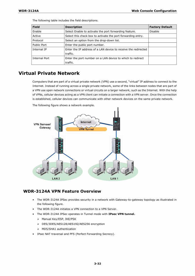
WDR-3124A Web Console Configuration
3-32
The following table includes the field descriptions.
Field Description Factory Default Enable Select Enable to activate the port forwarding feature. Disable
Active Select this check box to activate the port forwarding entry.
Protocol Select an option from the drop-down list.
Public Port Enter the public port number.
Internal IP Enter the IP address of a LAN device to receive the redirected traffic.
Internal Port Enter the port number on a LAN device to which to redirect traffic.
Virtual Private Network Computers that are part of a virtual private network (VPN) use a second, “virtual” IP address to connect to the Internet. Instead of running across a single private network, some of the links between nodes that are part of a VPN use open network connections or virtual circuits on a larger network, such as the Internet. With the help of VPNs, cellular devices acting as a VPN client can initiate a connection with a VPN server. Once the connection is established, cellular devices can communicate with other network devices on the same private network.
The following figure shows a network example.
WDR-3124A VPN Feature Overview
• The WDR-3124A IPSec provides security in a network with Gateway-to-gateway topology as illustrated in the following figure.
• The WDR-3124A initiates a VPN connection to a VPN Server.
• The WDR-3124A IPSec operates in Tunnel mode with IPsec VPN tunnel.
Manual Key/ESP, IKE/PSK
DES/3DES/AES128/AES192/AES256 encryption
MD5/SHA1 authentication
• IPsec NAT traversal and PFS (Perfect Forwarding Secrecy).
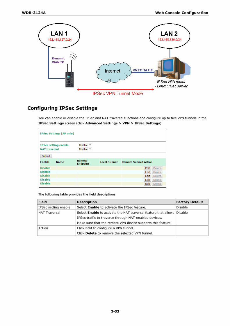
WDR-3124A Web Console Configuration
3-33
Configuring IPSec Settings
You can enable or disable the IPSec and NAT traversal functions and configure up to five VPN tunnels in the IPSec Settings screen (click Advanced Settings > VPN > IPSec Settings).
The following table provides the field descriptions.
Field Description Factory Default IPSec setting enable Select Enable to activate the IPSec feature. Disable
NAT Traversal Select Enable to activate the NAT traversal feature that allows IPSec traffic to traverse through NAT-enabled devices. Make sure that the remote VPN device supports this feature.
Disable
Action Click Edit to configure a VPN tunnel. Click Delete to remove the selected VPN tunnel.
Dynamic WAN IP

WDR-3124A Web Console Configuration
3-34
Configuring a VPN Tunnel
To configure a VPN tunnel, click Edit in the IPSec Settings screen.
The following table provides the field descriptions.
Field Description Factory Default IPSec enable Select Enable to activate the VPN tunnel. Disable
Connection name Enter a descriptive name for the VPN tunnel.
Connection type Select one of the following connection types: • Site-to-Site – Select this option to create a VPN tunnel for
static local and remote subnets. • Site-to-Site(any) – Select this option to create a VPN
tunnel between a static local subnet and a dynamic remote subnet.
Site-to-Site
Startup mode Select Start in Initial to set the WDR-3124A to initiate a connection with the remote VPN gateway. Select Wait for Connecting to set the WDR-3124A to wait for a remote VPN gateway to initiate a connection.
Start in Initial
Remote VPN gateway Enter the WAN IP address of the remote VPN gateway.
Local network Enter the remote VPN server subnet IP of the local network.
Local netmask Enter the remote VPN server subnet netmask of the local network.

WDR-3124A Web Console Configuration
3-35
Field Description Factory Default Local ID Enter an ID (IP/FQDN/User_FQDN) to identify and authenticate
the local VPN gateway.
Remote network Enter the remote VPN server subnet IP of the remote network.
Remote netmask Enter the remote VPN server subnet netmask of the remote network.
Remote ID Enter an ID (IP/FQDN/User_FQDN) to identify and authenticate the remote VPN endpoint.
Key Exchange (Phase1)
Operation mode Select main mode or aggressive mode to configure the standard negotiation parameters for IKE Phase 1 of the VPN Tunnel.
Main
Authentication mode Select Pre-shared key, RSA Signature or X.509 authentication mode to for phase 1 key exchange. The configuration fields vary depending on the authentication mode you select. For information on configuring each authentication mode, refer to the following sections.
Pre-shared key
Encryption algorithm Select the DES, 3DES, AES128, AES192 or AES256 of the VPN ISAKMP phase 1 encryption mode.
DES
Hash algorithm Select the MD5 or SHA-1 VPN key exchange phase 1 hash mode.
MD5
DH group Select the DH-2(1024) or DH-5(1536) VPN key exchange phase 1 Diffie-Hellman group. As the Diffie-Hellman Group number increases, the higher the level of encryption implemented for PFS.
DH-2
Negotiation time The number of allowed reconnect times when startup mode is initiated. If the number is 0, this tunnel will always try connecting to the remote gateway when the VPN tunnel is not created successfully.
0
IKE life time Enter the number of minutes for the VPN IKE SA phase 1 Lifetime. This is the period of time to pass before establishing a new IPSec security association (SA) with the remote endpoint.
60
Rekey expire time Enter the number of minutes for the Start to Rekey before IKE lifetime expired.
9
Rekey fuzz percent The rekey expire time will change randomly to enhance the security. Rekey fuzz percent is the maximum random change margin of the Rekey expire time. 100% means the rekey expire time will not change randomly.
100%
Data Exchange (phase2)
Perfect forward secrecy Enable or disable the Perfect Forward Secrecy. PFS is an additional security protocol.
Disable
SA life time Enter the number of seconds for the VPN ISAKMP phase 2 Lifetime. This is the period of time to pass before establishing a new IPSec security association (SA) with the remote endpoint.
480
Encryption algorithm Select the DES, 3DES, AES128, AES192 or AES256 of the VPN ISAKMP phase 1 encryption mode.
DES
Hash algorithm Select the MD5 or SHA-1 VPN ISAKMP phase 1 authentication mode.
MD5
Dead Peer Detection
DPD action When you enable the Dead Peer Detection (DPD) feature, the WDR-3124A performs one of the following actions when connection to a remote IPSec tunnel is down: • Hold: Keep the VPN tunnel • Clear: Clear the VPN tunnel
Disable
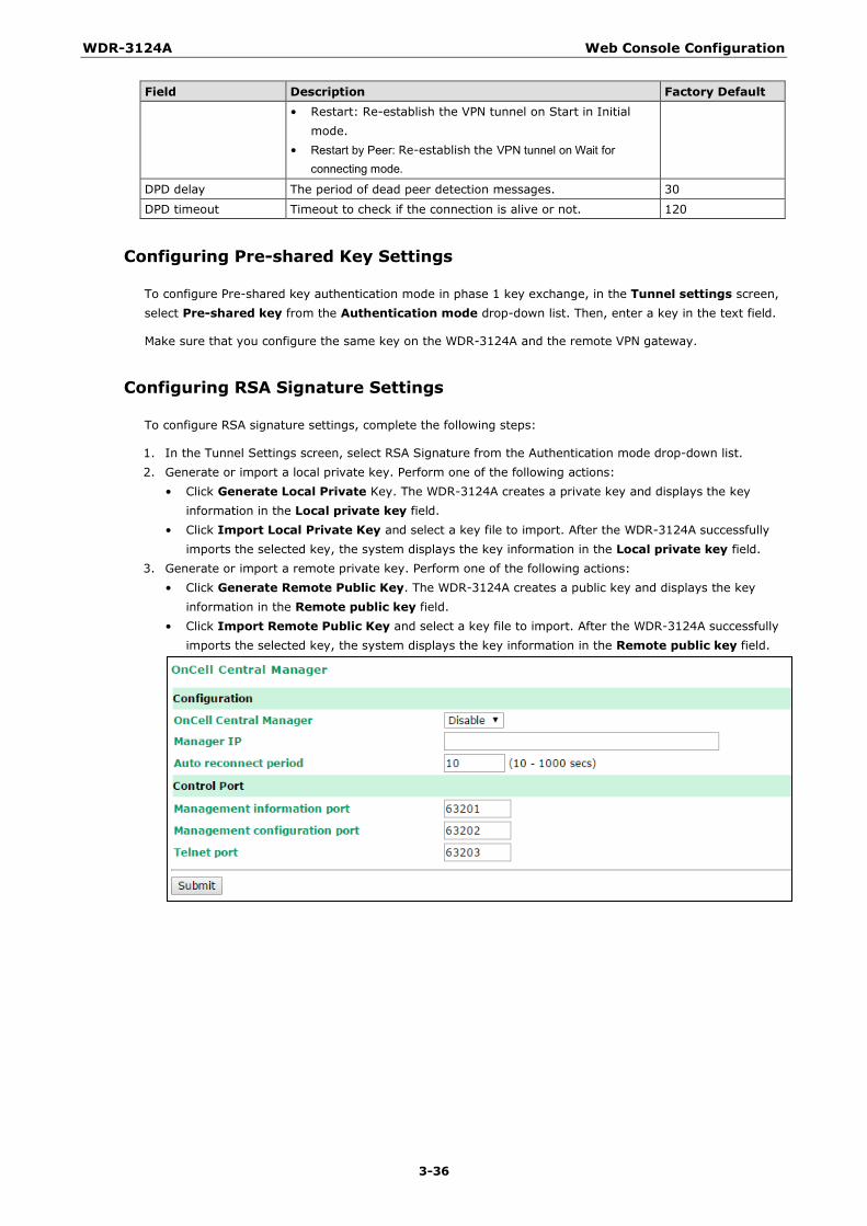
WDR-3124A Web Console Configuration
3-36
Field Description Factory Default • Restart: Re-establish the VPN tunnel on Start in Initial
mode. • Restart by Peer: Re-establish the VPN tunnel on Wait for
connecting mode.
DPD delay The period of dead peer detection messages. 30
DPD timeout Timeout to check if the connection is alive or not. 120
Configuring Pre-shared Key Settings
To configure Pre-shared key authentication mode in phase 1 key exchange, in the Tunnel settings screen, select Pre-shared key from the Authentication mode drop-down list. Then, enter a key in the text field.
Make sure that you configure the same key on the WDR-3124A and the remote VPN gateway.
Configuring RSA Signature Settings
To configure RSA signature settings, complete the following steps:
1. In the Tunnel Settings screen, select RSA Signature from the Authentication mode drop-down list. 2. Generate or import a local private key. Perform one of the following actions:
• Click Generate Local Private Key. The WDR-3124A creates a private key and displays the key information in the Local private key field.
• Click Import Local Private Key and select a key file to import. After the WDR-3124A successfully imports the selected key, the system displays the key information in the Local private key field.
3. Generate or import a remote private key. Perform one of the following actions: • Click Generate Remote Public Key. The WDR-3124A creates a public key and displays the key
information in the Remote public key field. • Click Import Remote Public Key and select a key file to import. After the WDR-3124A successfully
imports the selected key, the system displays the key information in the Remote public key field.
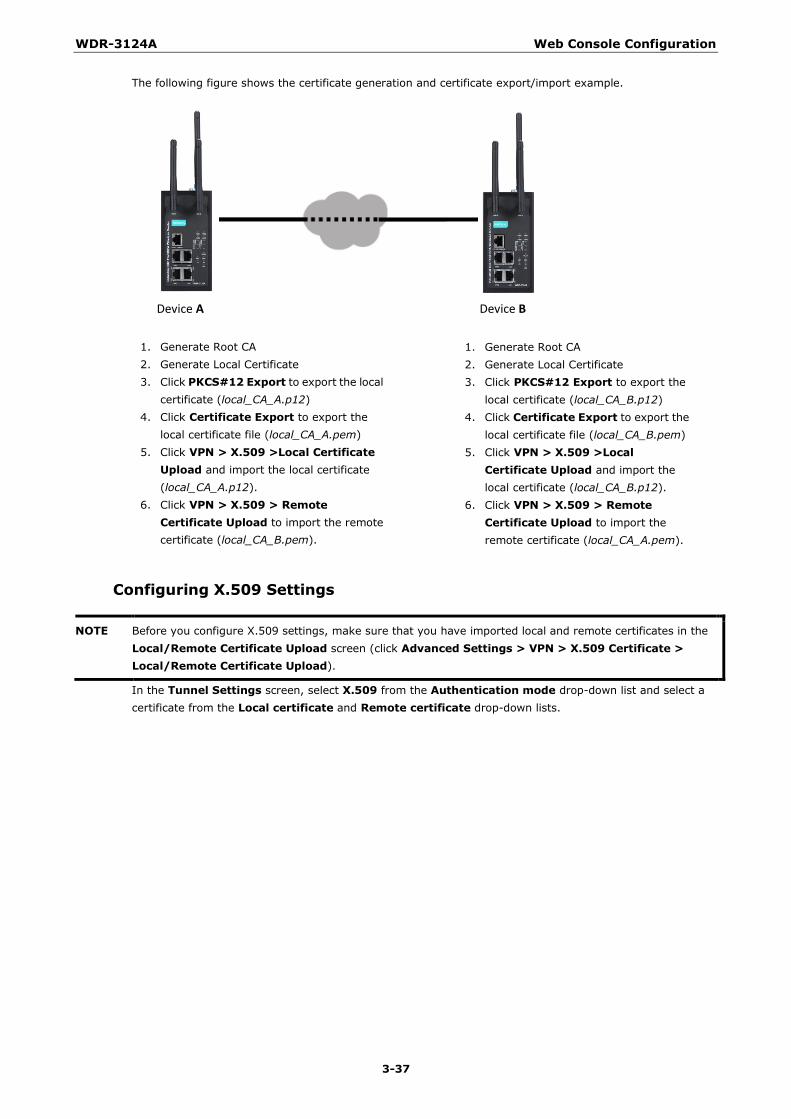
WDR-3124A Web Console Configuration
3-37
The following figure shows the certificate generation and certificate export/import example.
Configuring X.509 Settings
NOTE Before you configure X.509 settings, make sure that you have imported local and remote certificates in the Local/Remote Certificate Upload screen (click Advanced Settings > VPN > X.509 Certificate > Local/Remote Certificate Upload).
In the Tunnel Settings screen, select X.509 from the Authentication mode drop-down list and select a certificate from the Local certificate and Remote certificate drop-down lists.
Device A Device B
1. Generate Root CA 2. Generate Local Certificate 3. Click PKCS#12 Export to export the local
certificate (local_CA_A.p12) 4. Click Certificate Export to export the
local certificate file (local_CA_A.pem) 5. Click VPN > X.509 >Local Certificate
Upload and import the local certificate (local_CA_A.p12).
6. Click VPN > X.509 > Remote Certificate Upload to import the remote certificate (local_CA_B.pem).
1. Generate Root CA 2. Generate Local Certificate 3. Click PKCS#12 Export to export the
local certificate (local_CA_B.p12) 4. Click Certificate Export to export the
local certificate file (local_CA_B.pem) 5. Click VPN > X.509 >Local
Certificate Upload and import the local certificate (local_CA_B.p12).
6. Click VPN > X.509 > Remote Certificate Upload to import the remote certificate (local_CA_A.pem).
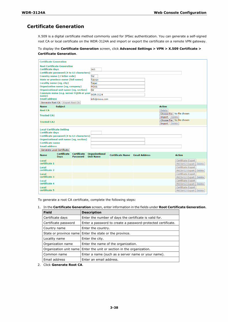
WDR-3124A Web Console Configuration
3-38
Certificate Generation
X.509 is a digital certificate method commonly used for IPSec authentication. You can generate a self-signed root CA or local certificate on the WDR-3124A and import or export the certificate on a remote VPN gateway.
To display the Certificate Generation screen, click Advanced Settings > VPN > X.509 Certificate > Certificate Generation.
To generate a root CA certificate, complete the following steps:
1. In the Certificate Generation screen, enter information in the fields under Root Certificate Generation.
Field Description Certificate days Enter the number of days the certificate is valid for.
Certificate password Enter a password to create a password-protected certificate.
Country name Enter the country.
State or province name Enter the state or the province.
Locality name Enter the city.
Organization name Enter the name of the organization.
Organization unit name Enter the unit or section in the organization.
Common name Enter a name (such as a server name or your name).
Email address Enter an email address.
2. Click Generate Root CA.

WDR-3124A Web Console Configuration
3-39
After you have generated the root CA certificate, generate a local certificate and export the key files. Complete the following steps:
1. In the Certificate Generation screen, enter information in the fields under Local Certificate Settings.
Field Description Certificate days Enter the number of days the certificate is valid for.
Certificate password Enter a password to create a password-protected certificate.
Organization unit name Enter the unit or section in the organization.
Common name Enter a name (such as a server name or your name).
Email address Enter an email address.
2. Click Generate Local Certificate. 3. Click Certificate Export to export the public key file for the certificate that you import on a remote VPN
gateway. 4. Click PKCS#12 Export to export the private key file for local certificates on the WDR-3124A. You can
import the local certificate in the Local Certificate Upload screen.
Local Certificate Upload
If you configure X.509 authentication mode for VPN tunnel setup, you must import a local certificate on the WDR-3124A.
You can add or delete a local certificate in the Local Certificate Upload screen.
1. Click Advanced Settings > VPN > X.509 Certificate > Local Certificate Upload. 2. In the PKCS#12 upload field, click Browse to select a local certificate. 3. In the Import password field, enter the certificate password. 4. Click Import.
NOTE You can generate a local certificate in the Certificate Generation screen.
Remote Certificate Upload
You can add or delete a certificate from the remote VPN gateway in the Remote Certificate Upload screen.
1. Click Advanced Settings > VPN > X.509 Certificate > Remote Certificate Upload. 2. In the Remote certificate upload field, click Browse to select a remote certificate. 3. Click Import.
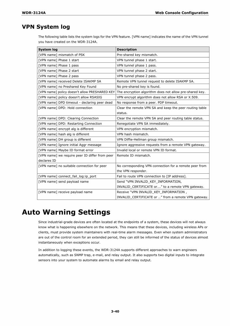
WDR-3124A Web Console Configuration
3-40
VPN System log The following table lists the system logs for the VPN feature. [VPN name] indicates the name of the VPN tunnel you have created on the WDR-3124A.
System log Description [VPN name] mismatch of PSK Pre-shared key mismatch.
[VPN name] Phase 1 start VPN tunnel phase 1 start.
[VPN name] Phase 1 pass VPN tunnel phase 1 pass.
[VPN name] Phase 2 start VPN tunnel phase 2 start.
[VPN name] Phase 2 pass VPN tunnel phase 2 pass.
[VPN name] received Delete ISAKMP SA Remote VPN tunnel request to delete ISAKMP SA.
[VPN name] no Preshared Key Found No pre-shared key is found.
[VPN name] policy doesn't allow PRESHARED KEY The encryption algorithm does not allow pre-shared key.
[VPN name] policy doesn't allow RSASIG VPN encrypt algorithm does not allow RSA or X.509.
[VPN name] DPD timeout - declaring peer dead No response from a peer. PDP timeout.
[VPN name] DPD: Hold connection Clear the remote VPN SA and keep the peer routing table status.
[VPN name] DPD: Clearing Connection Clear the remote VPN SA and peer routing table status.
[VPN name] DPD: Restarting Connection Renegotiate VPN SA immediately.
[VPN name] encrypt alg is different VPN encryption mismatch.
[VPN name] hash alg is different VPN hash mismatch.
[VPN name] DH group is different VPN Diffie-Hellman group mismatch.
[VPN name] Ignore initial Aggr message Ignore aggressive requests from a remote VPN gateway.
[VPN name] Maybe ID format error Invalid local or remote VPN ID format.
[VPN name] we require peer ID differ from peer declares ID
Remote ID mismatch.
[VPN name] no suitable connection for peer No corresponding VPN connection for a remote peer from the VPN responder.
[VPN name] connect_fail_log:ip_port Fail to route VPN connection to [IP address].
[VPN name] send payload name Send “VPN INVALID_KEY_INFORMATION, INVALID_CERTIFICATE or….” to a remote VPN gateway.
[VPN name] receive payload name Receive “VPN INVALID_KEY_INFORMATION , INVALID_CERTIFICATE or …” from a remote VPN gateway.
Auto Warning Settings Since industrial-grade devices are often located at the endpoints of a system, these devices will not always know what is happening elsewhere on the network. This means that these devices, including wireless APs or clients, must provide system maintainers with real-time alarm messages. Even when system administrators are out of the control room for an extended period, they can still be informed of the status of devices almost instantaneously when exceptions occur.
In addition to logging these events, the WDR-3124A supports different approaches to warn engineers automatically, such as SNMP trap, e-mail, and relay output. It also supports two digital inputs to integrate sensors into your system to automate alarms by email and relay output.
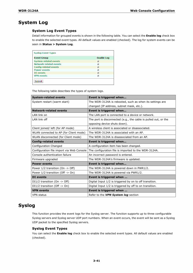
WDR-3124A Web Console Configuration
3-41
System Log
System Log Event Types Detail information for grouped events is shown in the following table. You can select the Enable log check box to enable the selected event types. All default values are enabled (checked). The log for system events can be seen in Status > System Log.
The following table describes the types of system logs.
System-related events Event is triggered when… System restart (warm start) The WDR-3124A is rebooted, such as when its settings are
changed (IP address, subnet mask, etc.).
Network-related events Event is triggered when… LAN link on The LAN port is connected to a device or network.
LAN link off The port is disconnected (e.g., the cable is pulled out, or the opposing device shuts down).
Client joined/ left (for AP mode) A wireless client is associated or disassociated.
WLAN connected to AP (for Client mode) The WDR-3124A is associated with an AP.
WLAN disconnected (for Client mode) The WDR-3124A is disassociated from an AP.
Config-related events Event is triggered when… Configuration Changed A configuration item has been changed.
Configuration file import via Web Console The configuration file is imported to the WDR-3124A.
Console authentication failure An incorrect password is entered.
Firmware upgraded The WDR-3124A’s firmware is updated.
Power events Event is triggered when… Power 1/2 transition (On -> Off) The WDR-3124A is powered down in PWR1/2.
Power 1/2 transition (Off -> On) The WDR-3124A is powered via PWR1/2.
DI events Event is triggered when … DI1/2 transition (On -> Off) Digital Input 1/2 is triggered by on to off transition.
DI1/2 transition (Off -> On) Digital Input 1/2 is triggered by off to on transition.
VPN events Event is triggered when … VPN status Refer to the VPN System log section
Syslog This function provides the event logs for the Syslog server. The function supports up to three configurable Syslog servers and Syslog server UDP port numbers. When an event occurs, the event will be sent as a Syslog UDP packet to the specified Syslog servers.
Syslog Event Types You can select the Enable log check box to enable the selected event types. All default values are enabled (checked).
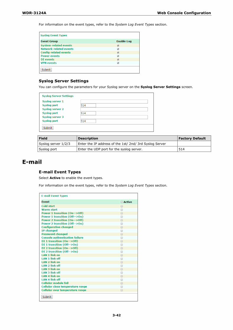
WDR-3124A Web Console Configuration
3-42
For information on the event types, refer to the System Log Event Types section.
Syslog Server Settings You can configure the parameters for your Syslog server on the Syslog Server Settings screen.
Field Description Factory Default Syslog server 1/2/3 Enter the IP address of the 1st/ 2nd/ 3rd Syslog Server
Syslog port Enter the UDP port for the syslog server. 514
E-mail Event Types Select Active to enable the event types.
For information on the event types, refer to the System Log Event Types section.
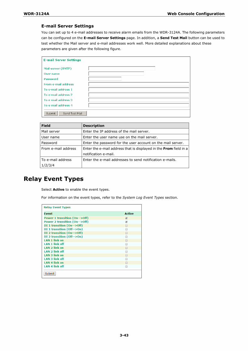
WDR-3124A Web Console Configuration
3-43
E-mail Server Settings You can set up to 4 e-mail addresses to receive alarm emails from the WDR-3124A. The following parameters can be configured on the E-mail Server Settings page. In addition, a Send Test Mail button can be used to test whether the Mail server and e-mail addresses work well. More detailed explanations about these parameters are given after the following figure.
Field Description Mail server Enter the IP address of the mail server.
User name Enter the user name use on the mail server.
Password Enter the password for the user account on the mail server.
From e-mail address Enter the e-mail address that is displayed in the From field in a notification e-mail.
To e-mail address 1/2/3/4
Enter the e-mail addresses to send notification e-mails.
Relay Event Types Select Active to enable the event types.
For information on the event types, refer to the System Log Event Types section.
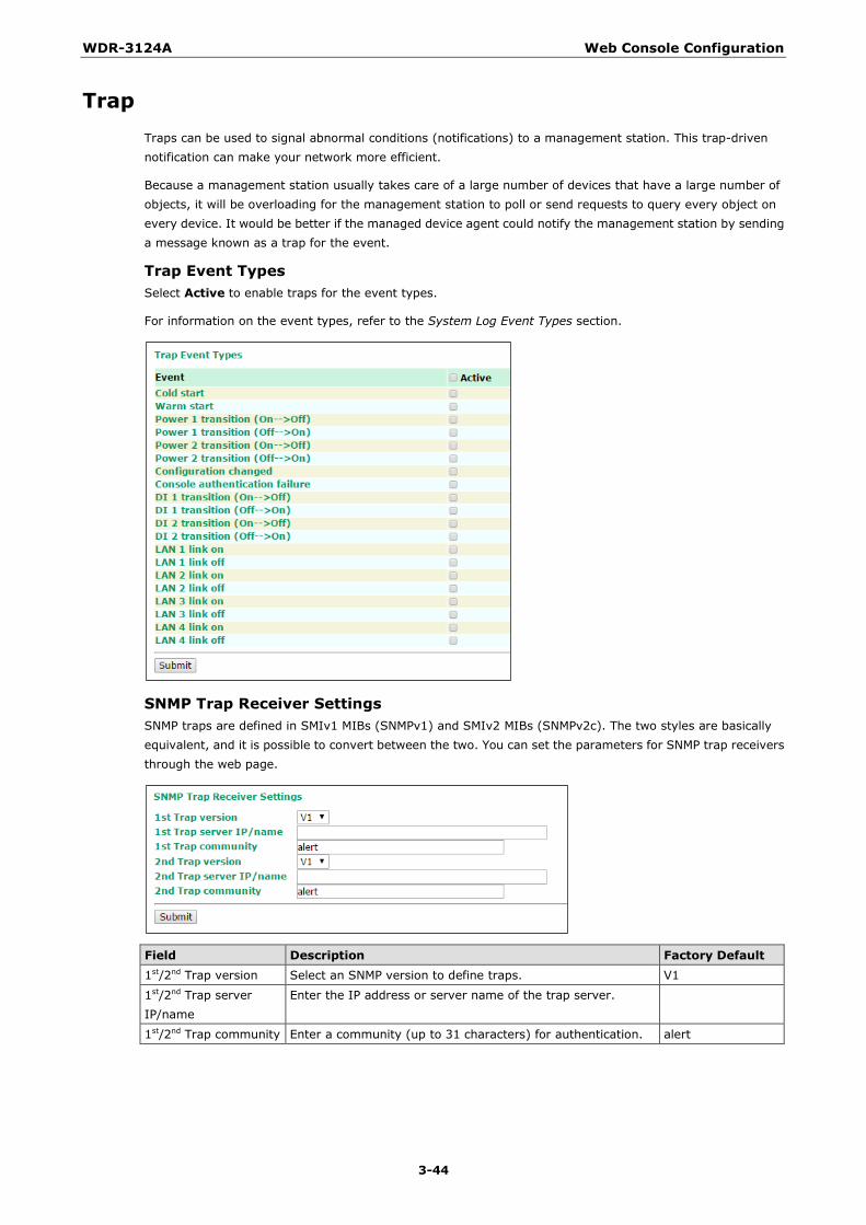
WDR-3124A Web Console Configuration
3-44
Trap Traps can be used to signal abnormal conditions (notifications) to a management station. This trap-driven notification can make your network more efficient.
Because a management station usually takes care of a large number of devices that have a large number of objects, it will be overloading for the management station to poll or send requests to query every object on every device. It would be better if the managed device agent could notify the management station by sending a message known as a trap for the event.
Trap Event Types Select Active to enable traps for the event types.
For information on the event types, refer to the System Log Event Types section.
SNMP Trap Receiver Settings SNMP traps are defined in SMIv1 MIBs (SNMPv1) and SMIv2 MIBs (SNMPv2c). The two styles are basically equivalent, and it is possible to convert between the two. You can set the parameters for SNMP trap receivers through the web page.
Field Description Factory Default 1st/2nd Trap version Select an SNMP version to define traps. V1
1st/2nd Trap server IP/name
Enter the IP address or server name of the trap server.
1st/2nd Trap community Enter a community (up to 31 characters) for authentication. alert
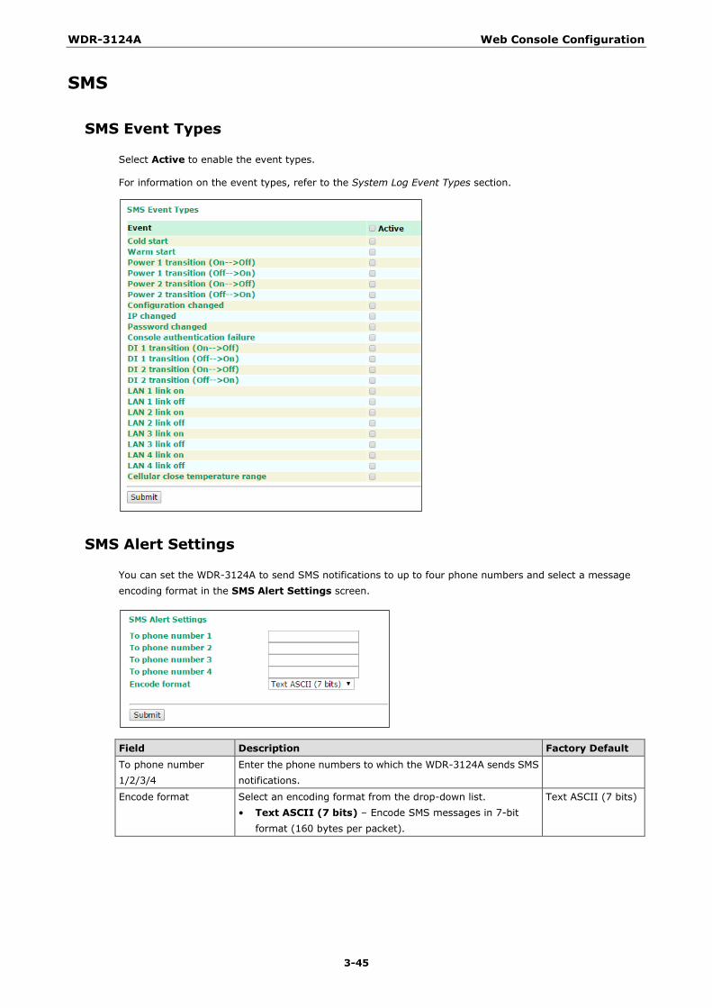
WDR-3124A Web Console Configuration
3-45
SMS
SMS Event Types
Select Active to enable the event types.
For information on the event types, refer to the System Log Event Types section.
SMS Alert Settings
You can set the WDR-3124A to send SMS notifications to up to four phone numbers and select a message encoding format in the SMS Alert Settings screen.
Field Description Factory Default To phone number 1/2/3/4
Enter the phone numbers to which the WDR-3124A sends SMS notifications.
Encode format Select an encoding format from the drop-down list. • Text ASCII (7 bits) – Encode SMS messages in 7-bit
format (160 bytes per packet).
Text ASCII (7 bits)

WDR-3124A Web Console Configuration
3-46
Status
Wireless Status The status for 802.11 info parameters, such as Operation mode and Channel, are shown on the Wireless Status page. The status will refresh every 5 seconds if the Auto refresh box is checked.
Certain values for 802.11 info may not show up due to different operation modes. As a result, Current BSSID and Signal strength are not available in AP mode.
It is helpful to use the continuously updated information on this page, such as Signal strength, to monitor the signal strength of the WDR-3124A in Client mode.
DNS Information The DNS information screen displays the DNS server to which the WDR-3124A is connected and the DNS server information.
SIM Status The SIM Status screen displays the current SIM card in use and the status of the SIM cards installed in the WDR-3124A.
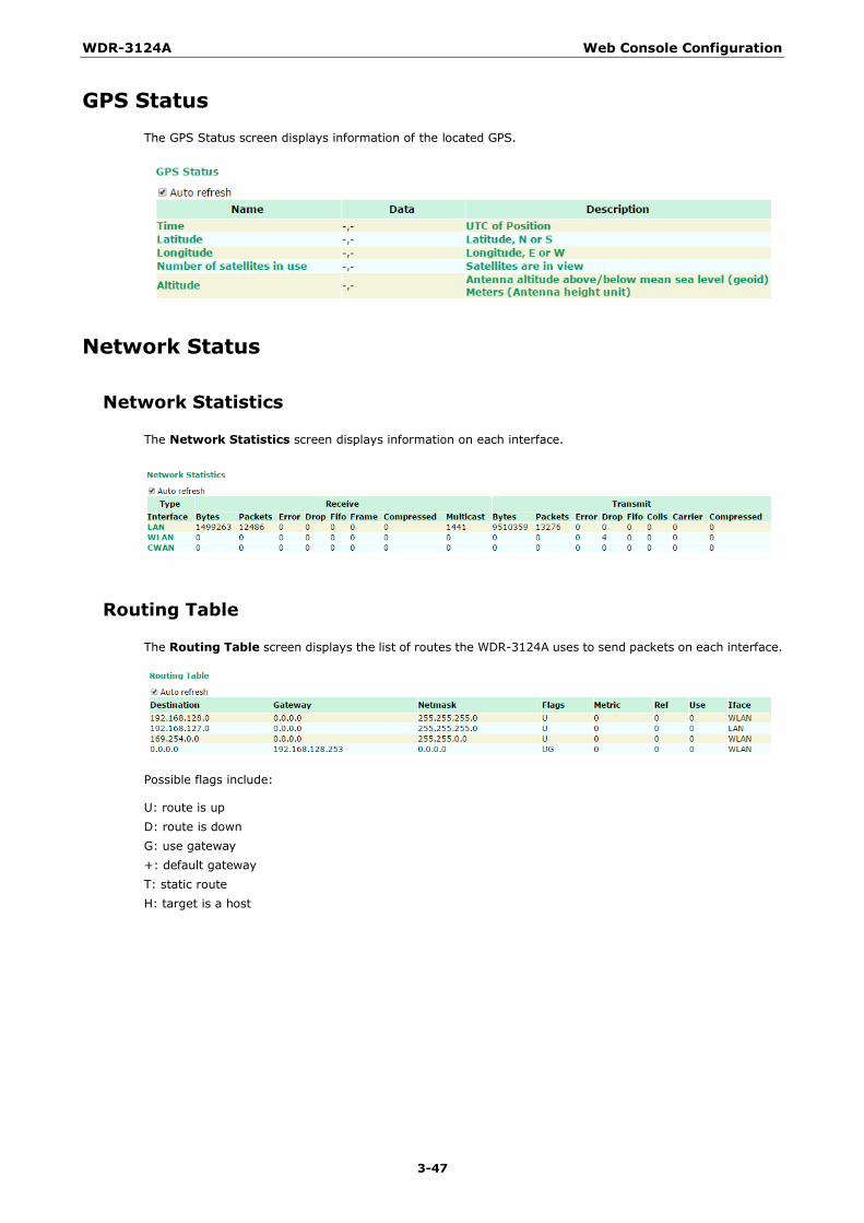
WDR-3124A Web Console Configuration
3-47
GPS Status The GPS Status screen displays information of the located GPS.
Network Status
Network Statistics
The Network Statistics screen displays information on each interface.
Routing Table
The Routing Table screen displays the list of routes the WDR-3124A uses to send packets on each interface.
Possible flags include:
U: route is up D: route is down G: use gateway +: default gateway T: static route H: target is a host
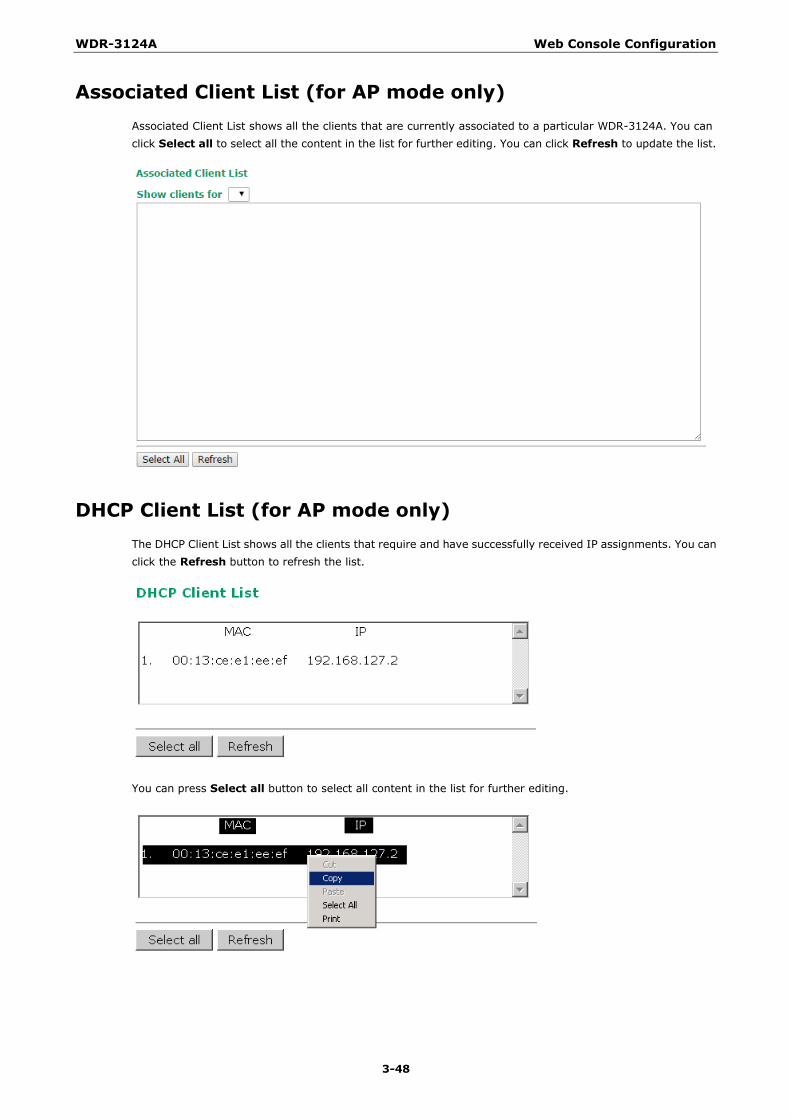
WDR-3124A Web Console Configuration
3-48
Associated Client List (for AP mode only) Associated Client List shows all the clients that are currently associated to a particular WDR-3124A. You can click Select all to select all the content in the list for further editing. You can click Refresh to update the list.
DHCP Client List (for AP mode only) The DHCP Client List shows all the clients that require and have successfully received IP assignments. You can click the Refresh button to refresh the list.
You can press Select all button to select all content in the list for further editing.
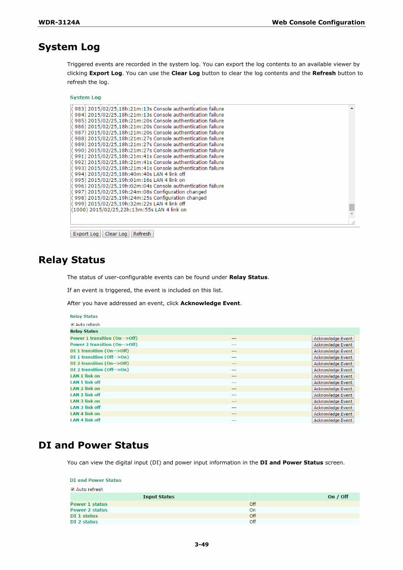
WDR-3124A Web Console Configuration
3-49
System Log Triggered events are recorded in the system log. You can export the log contents to an available viewer by clicking Export Log. You can use the Clear Log button to clear the log contents and the Refresh button to refresh the log.
Relay Status The status of user-configurable events can be found under Relay Status.
If an event is triggered, the event is included on this list.
After you have addressed an event, click Acknowledge Event.
DI and Power Status You can view the digital input (DI) and power input information in the DI and Power Status screen.
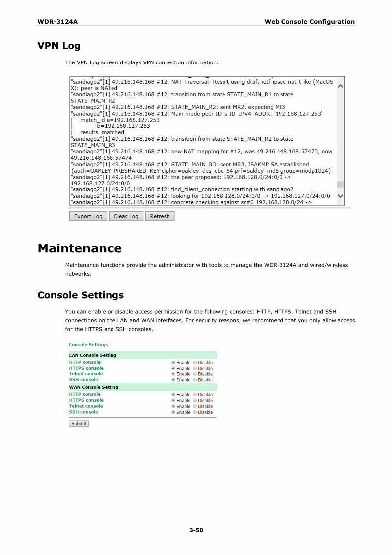
WDR-3124A Web Console Configuration
3-50
VPN Log The VPN Log screen displays VPN connection information.
Maintenance Maintenance functions provide the administrator with tools to manage the WDR-3124A and wired/wireless networks.
Console Settings You can enable or disable access permission for the following consoles: HTTP, HTTPS, Telnet and SSH connections on the LAN and WAN interfaces. For security reasons, we recommend that you only allow access for the HTTPS and SSH consoles.

WDR-3124A Web Console Configuration
3-51
Ping Ping helps to diagnose the integrity of wired or wireless networks. By inputting a node’s IP address in the Destination field, you can use the ping command to make sure it exists and whether or not the access path is available.
If the node and access path are available, you will see that all packets were successfully transmitted with no loss. Otherwise, some, or even all, packets may get lost, as shown in the following figure.
Firmware Upgrade The WDR-3124A can be enhanced with more value-added functions by installing firmware upgrades. The latest firmware is available at Moxa’s download center.
Before running a firmware upgrade, make sure the WDR-3124A is off-line. Click Choose File to select the firmware image file and click Firmware Upgrade and Restart to start the firmware upgrade. After the progress bar reaches 100%, the WDR-3124A will reboot itself.
When upgrading your firmware, the WDR-3124A’s other functions are forbidden.
ATTENTION
Please make sure the power source is stable when you upgrade your firmware. An unexpected power breakup may damage your WDR-3124A.
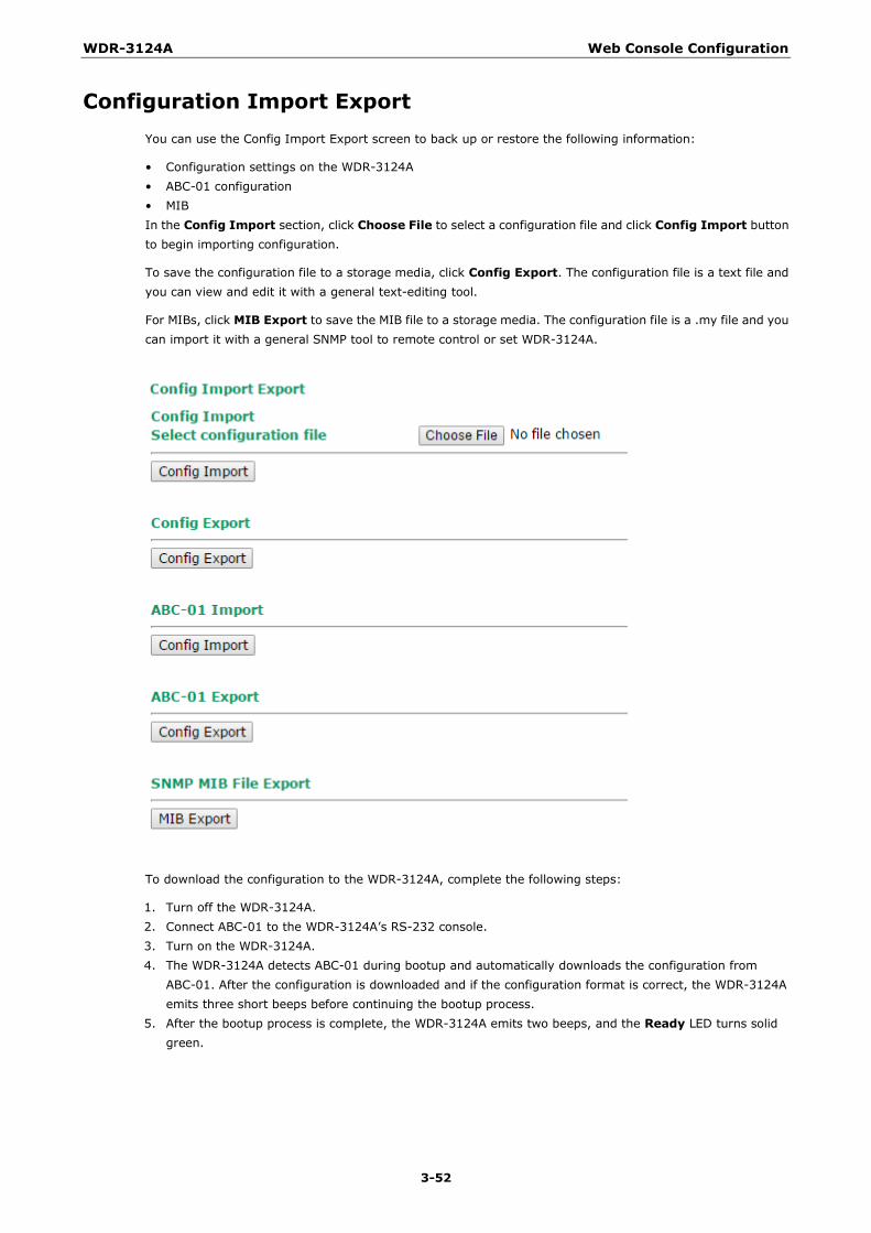
WDR-3124A Web Console Configuration
3-52
Configuration Import Export You can use the Config Import Export screen to back up or restore the following information:
• Configuration settings on the WDR-3124A • ABC-01 configuration • MIB In the Config Import section, click Choose File to select a configuration file and click Config Import button to begin importing configuration.
To save the configuration file to a storage media, click Config Export. The configuration file is a text file and you can view and edit it with a general text-editing tool.
For MIBs, click MIB Export to save the MIB file to a storage media. The configuration file is a .my file and you can import it with a general SNMP tool to remote control or set WDR-3124A.
To download the configuration to the WDR-3124A, complete the following steps:
1. Turn off the WDR-3124A. 2. Connect ABC-01 to the WDR-3124A’s RS-232 console. 3. Turn on the WDR-3124A. 4. The WDR-3124A detects ABC-01 during bootup and automatically downloads the configuration from
ABC-01. After the configuration is downloaded and if the configuration format is correct, the WDR-3124A emits three short beeps before continuing the bootup process.
5. After the bootup process is complete, the WDR-3124A emits two beeps, and the Ready LED turns solid green.
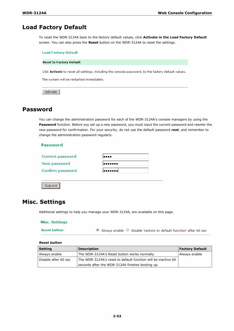
WDR-3124A Web Console Configuration
3-53
Load Factory Default To reset the WDR-3124A back to the factory default values, click Activate in the Load Factory Default screen. You can also press the Reset button on the WDR-3124A to reset the settings.
Password You can change the administration password for each of the WDR-3124A’s console managers by using the Password function. Before you set up a new password, you must input the current password and reenter the new password for confirmation. For your security, do not use the default password root, and remember to change the administration password regularly.
Misc. Settings Additional settings to help you manage your WDR-3124A, are available on this page.
Reset button
Setting Description Factory Default Always enable The WDR-3124A’s Reset button works normally. Always enable
Disable after 60 sec The WDR-3124A’s reset to default function will be inactive 60 seconds after the WDR-3124A finishes booting up.
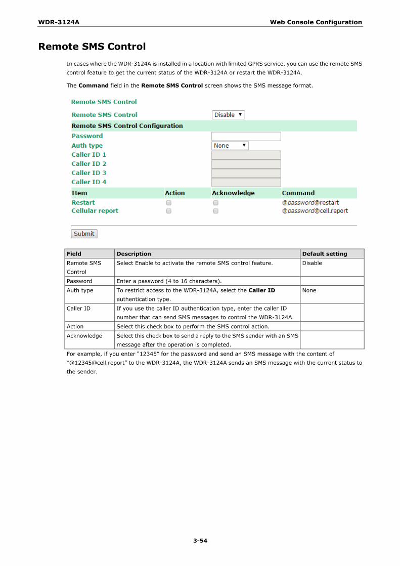
WDR-3124A Web Console Configuration
3-54
Remote SMS Control In cases where the WDR-3124A is installed in a location with limited GPRS service, you can use the remote SMS control feature to get the current status of the WDR-3124A or restart the WDR-3124A.
The Command field in the Remote SMS Control screen shows the SMS message format.
Field Description Default setting Remote SMS Control
Select Enable to activate the remote SMS control feature. Disable
Password Enter a password (4 to 16 characters).
Auth type To restrict access to the WDR-3124A, select the Caller ID authentication type.
None
Caller ID If you use the caller ID authentication type, enter the caller ID number that can send SMS messages to control the WDR-3124A.
Action Select this check box to perform the SMS control action.
Acknowledge Select this check box to send a reply to the SMS sender with an SMS message after the operation is completed.
For example, if you enter “12345” for the password and send an SMS message with the content of “@[email protected]” to the WDR-3124A, the WDR-3124A sends an SMS message with the current status to the sender.

WDR-3124A Web Console Configuration
3-55
Save Configuration The following figure shows how the WDR-3124A stores the setting changes into volatile and non-volatile memory. All data stored in volatile memory will disappear when the WDR-3124A is shutdown or rebooted unless they are y. Because the WDR-3124A starts up and initializes with the settings stored in flash memory, all new changes must be saved to flash memory before restarting the WDR-3124A.
This also means the new changes will not work unless you run either the Save Configuration function or the Restart function.
After you click on Save Configuration in the left menu box, the following screen will appear. Click Save if you wish to update the configuration settings in the flash memory at this time. Alternatively, you may choose to run other functions and put off saving the configuration until later. However, the new setting changes will remain in the non-volatile memory until you save the configurations.
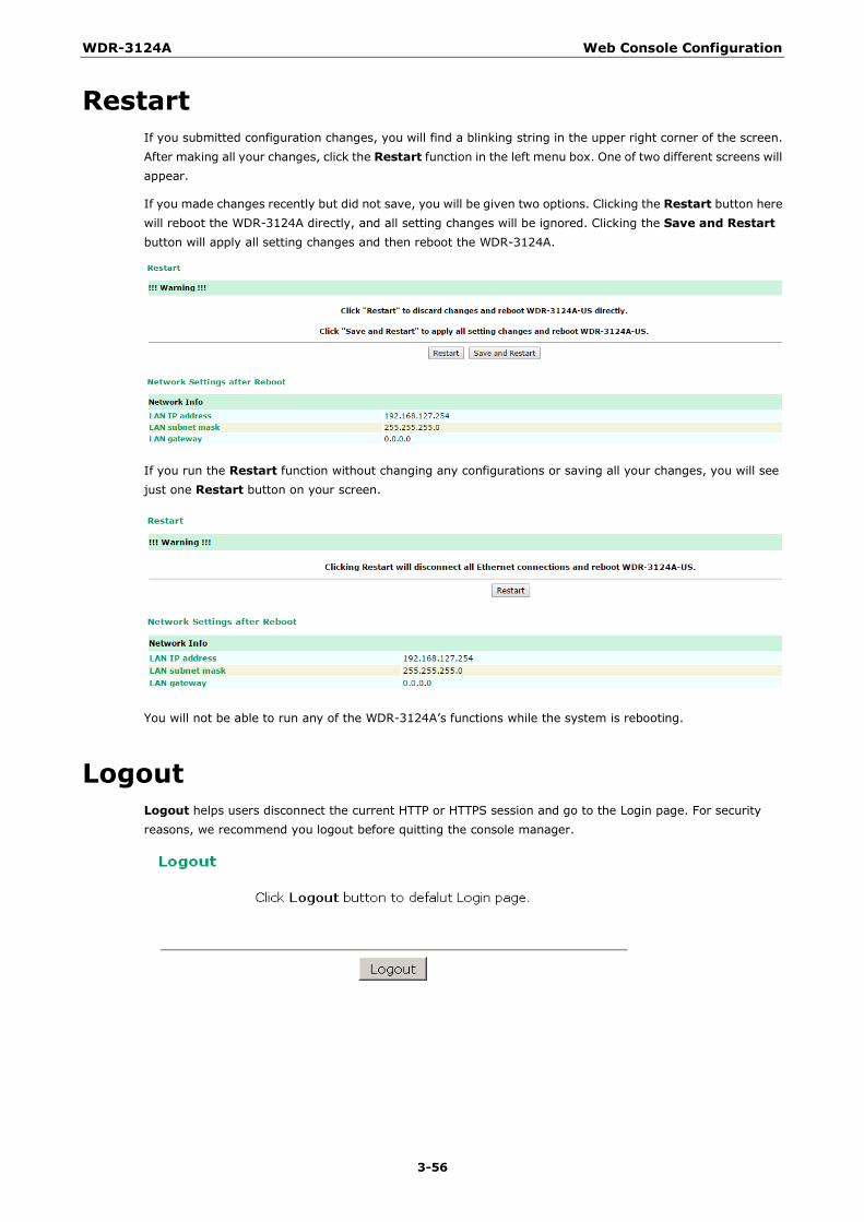
WDR-3124A Web Console Configuration
3-56
Restart If you submitted configuration changes, you will find a blinking string in the upper right corner of the screen. After making all your changes, click the Restart function in the left menu box. One of two different screens will appear.
If you made changes recently but did not save, you will be given two options. Clicking the Restart button here will reboot the WDR-3124A directly, and all setting changes will be ignored. Clicking the Save and Restart button will apply all setting changes and then reboot the WDR-3124A.
If you run the Restart function without changing any configurations or saving all your changes, you will see just one Restart button on your screen.
You will not be able to run any of the WDR-3124A’s functions while the system is rebooting.
Logout Logout helps users disconnect the current HTTP or HTTPS session and go to the Login page. For security reasons, we recommend you logout before quitting the console manager.

4 4. Software Installation and Configuration
The following topics are covered in this chapter:
Overview
Wireless Search Utility
Installing the Wireless Search Utility
Configuring the Wireless Search Utility
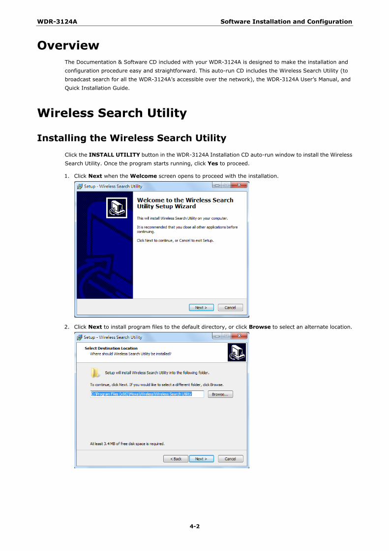
WDR-3124A Software Installation and Configuration
4-2
Overview The Documentation & Software CD included with your WDR-3124A is designed to make the installation and configuration procedure easy and straightforward. This auto-run CD includes the Wireless Search Utility (to broadcast search for all the WDR-3124A’s accessible over the network), the WDR-3124A User’s Manual, and Quick Installation Guide.
Wireless Search Utility
Installing the Wireless Search Utility Click the INSTALL UTILITY button in the WDR-3124A Installation CD auto-run window to install the Wireless Search Utility. Once the program starts running, click Yes to proceed.
1. Click Next when the Welcome screen opens to proceed with the installation.
2. Click Next to install program files to the default directory, or click Browse to select an alternate location.
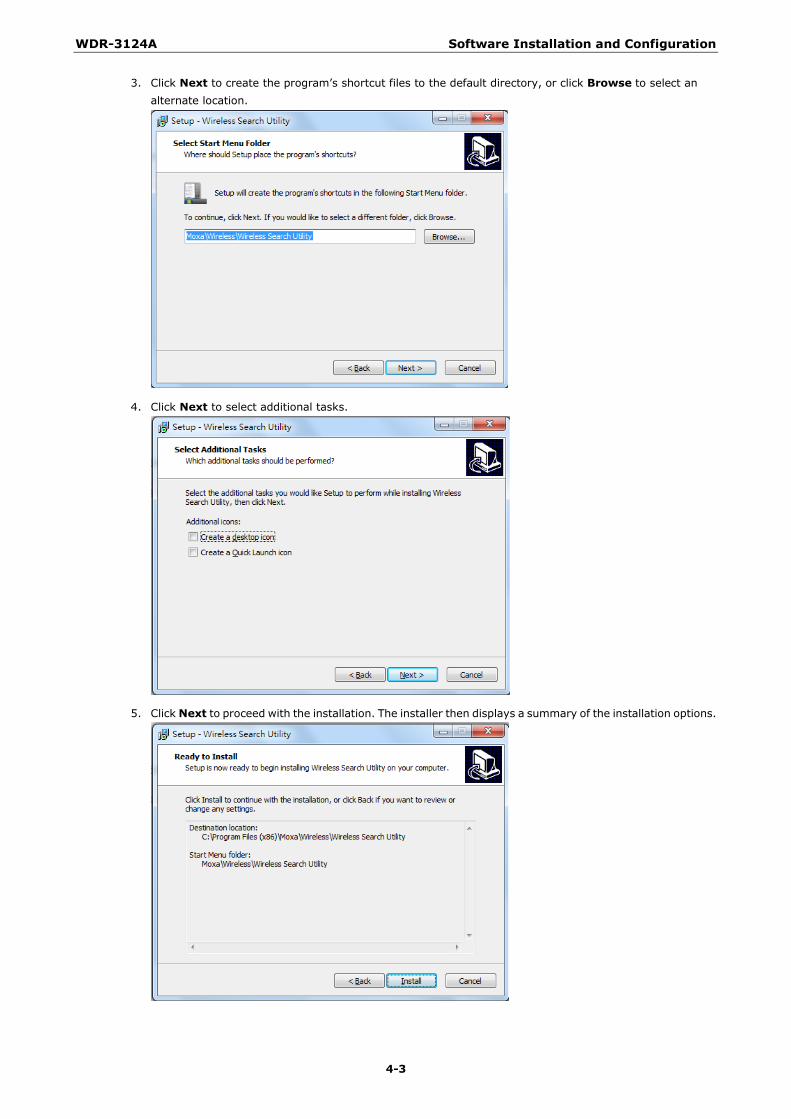
WDR-3124A Software Installation and Configuration
4-3
3. Click Next to create the program’s shortcut files to the default directory, or click Browse to select an alternate location.
4. Click Next to select additional tasks.
5. Click Next to proceed with the installation. The installer then displays a summary of the installation options.
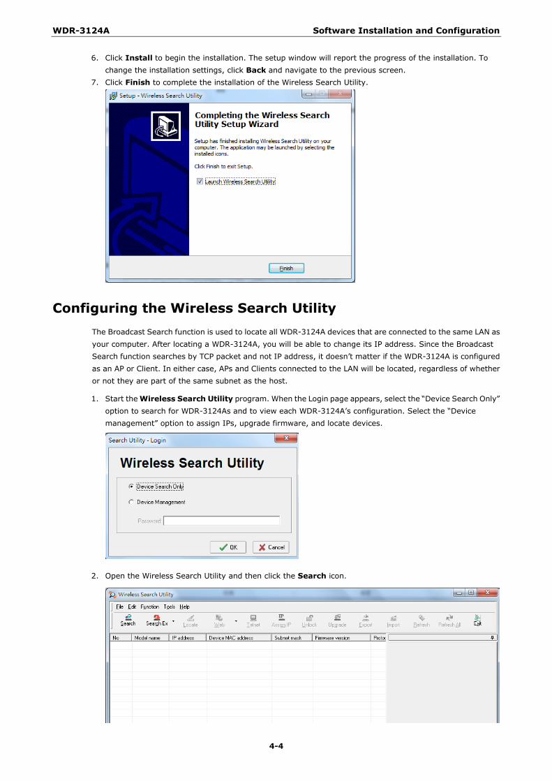
WDR-3124A Software Installation and Configuration
4-4
6. Click Install to begin the installation. The setup window will report the progress of the installation. To change the installation settings, click Back and navigate to the previous screen.
7. Click Finish to complete the installation of the Wireless Search Utility.
Configuring the Wireless Search Utility The Broadcast Search function is used to locate all WDR-3124A devices that are connected to the same LAN as your computer. After locating a WDR-3124A, you will be able to change its IP address. Since the Broadcast Search function searches by TCP packet and not IP address, it doesn’t matter if the WDR-3124A is configured as an AP or Client. In either case, APs and Clients connected to the LAN will be located, regardless of whether or not they are part of the same subnet as the host.
1. Start the Wireless Search Utility program. When the Login page appears, select the “Device Search Only” option to search for WDR-3124As and to view each WDR-3124A’s configuration. Select the “Device management” option to assign IPs, upgrade firmware, and locate devices.
2. Open the Wireless Search Utility and then click the Search icon.
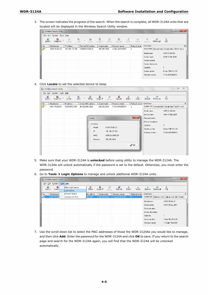
WDR-3124A Software Installation and Configuration
4-5
3. The screen indicates the progress of the search. When the search is complete, all WDR-3124A units that are located will be displayed in the Wireless Search Utility window.
4. Click Locate to set the selected device to beep.
5. Make sure that your WDR-3124A is unlocked before using utility to manage the WDR-3124A. The WDR-3124A will unlock automatically if the password is set to the default. Otherwise, you must enter the password.
6. Go to Tools Login Options to manage and unlock additional WDR-3124A units.
7. Use the scroll down list to select the MAC addresses of those the WDR-3124As you would like to manage, and then click Add. Enter the password for the WDR-3124A and click OK to save. If you return to the search page and search for the WDR-3124A again, you will find that the WDR-3124A will be unlocked automatically.
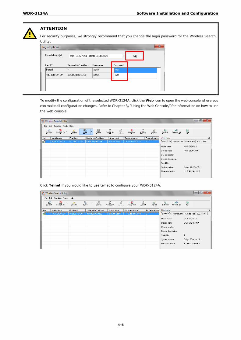
WDR-3124A Software Installation and Configuration
4-6
ATTENTION
For security purposes, we strongly recommend that you change the login password for the Wireless Search Utility.
To modify the configuration of the selected WDR-3124A, click the Web icon to open the web console where you can make all configuration changes. Refer to Chapter 3, “Using the Web Console,” for information on how to use the web console.
Click Telnet if you would like to use telnet to configure your WDR-3124A.
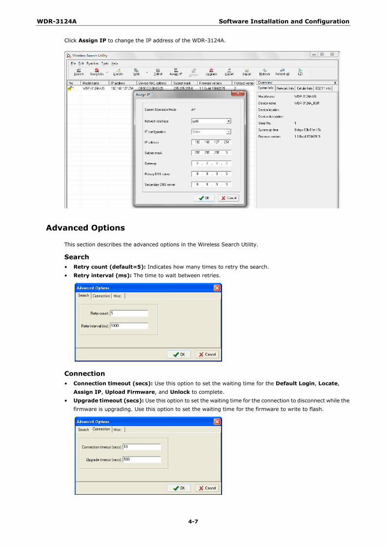
WDR-3124A Software Installation and Configuration
4-7
Click Assign IP to change the IP address of the WDR-3124A.
Advanced Options
This section describes the advanced options in the Wireless Search Utility.
Search • Retry count (default=5): Indicates how many times to retry the search. • Retry interval (ms): The time to wait between retries.
Connection • Connection timeout (secs): Use this option to set the waiting time for the Default Login, Locate,
Assign IP, Upload Firmware, and Unlock to complete. • Upgrade timeout (secs): Use this option to set the waiting time for the connection to disconnect while the
firmware is upgrading. Use this option to set the waiting time for the firmware to write to flash.
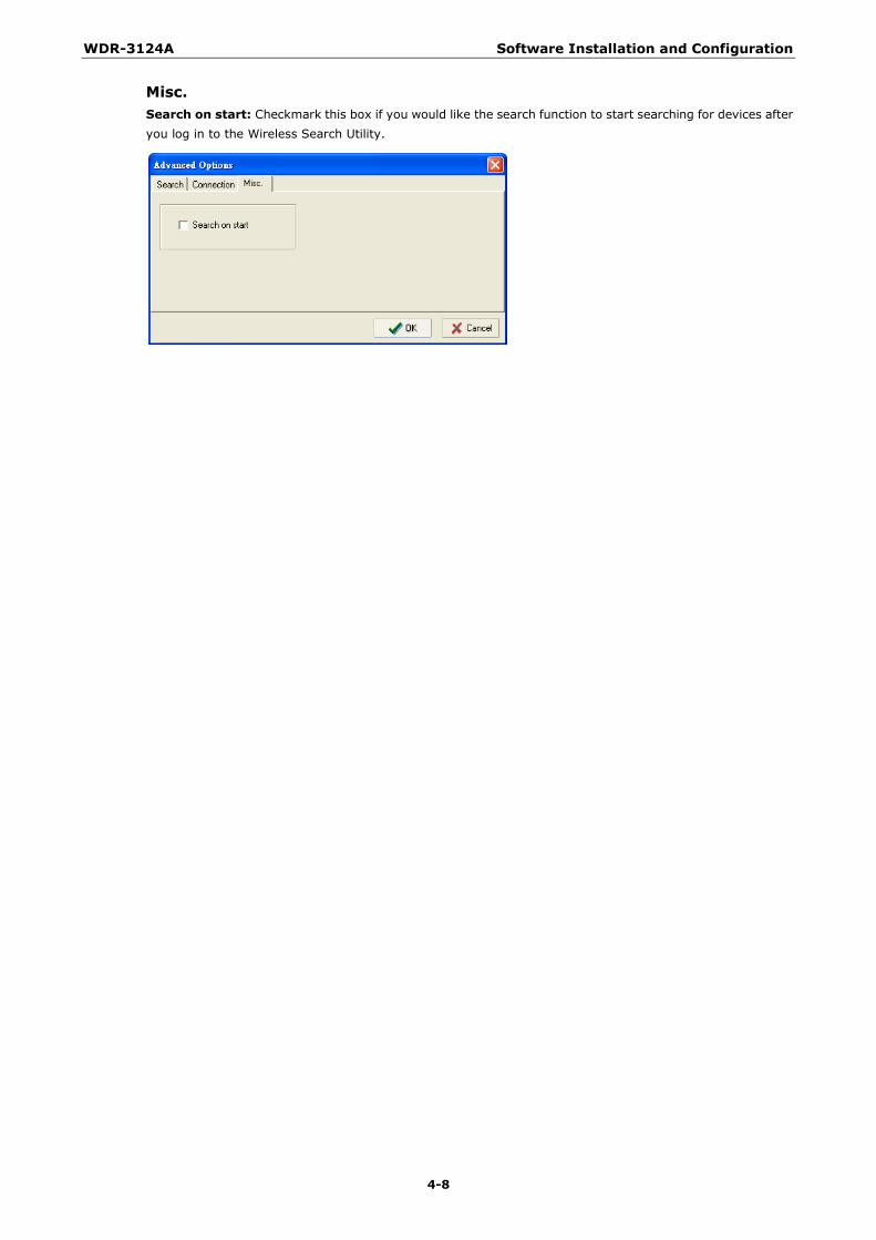
WDR-3124A Software Installation and Configuration
4-8
Misc. Search on start: Checkmark this box if you would like the search function to start searching for devices after you log in to the Wireless Search Utility.

A A. References
This chapter provides more detailed information about wireless-related technologies. The information in this chapter can help you administer your WDR-3124A units and plan your industrial wireless network better.
The following topics are covered in this appendix:
Beacon
DTIM
Fragment
RTS Threshold
WDR-3124A References
A-2
Beacon A beacon is a packet broadcast by the AP to keep the network synchronized. A beacon includes the wireless LAN service area, the AP address, the Broadcast destination address, a time stamp, Delivery Traffic Indicator Maps (DTIM), and the Traffic Indicator Message (TIM). Beacon Interval indicates the frequency interval of AP.
DTIM Delivery Traffic Indication Map (DTIM) is contained in beacon frames. It is used to indicate that broadcast and multicast frames buffered by the AP will be delivered shortly. Lower settings result in more efficient networking, while preventing your PC from dropping into power-saving sleep mode. Higher settings allow your PC to enter sleep mode, thus saving power.
Fragment A lower setting means smaller packets, which will create more packets for each transmission. If you have decreased this value and experience high packet error rates, you can increase it again, but it will likely decrease overall network performance. Only minor modifications of this value are recommended.
RTS Threshold RTS Threshold (256-2346) – This setting determines how large a packet can be before the Access Point coordinates transmission and reception to ensure efficient communication. This value should remain at its default setting of 2,346. When you encounter inconsistent data flow, only minor modifications are recommended.
B B. Supporting Information
This chapter presents additional information about this product. You can also learn how to contact Moxa for technical support.
The following topics are covered in this appendix:
Firmware Recovery
DoC (Declaration of Conformity)
Federal Communication Commission Interference Statement
R&TTE Compliance Statement
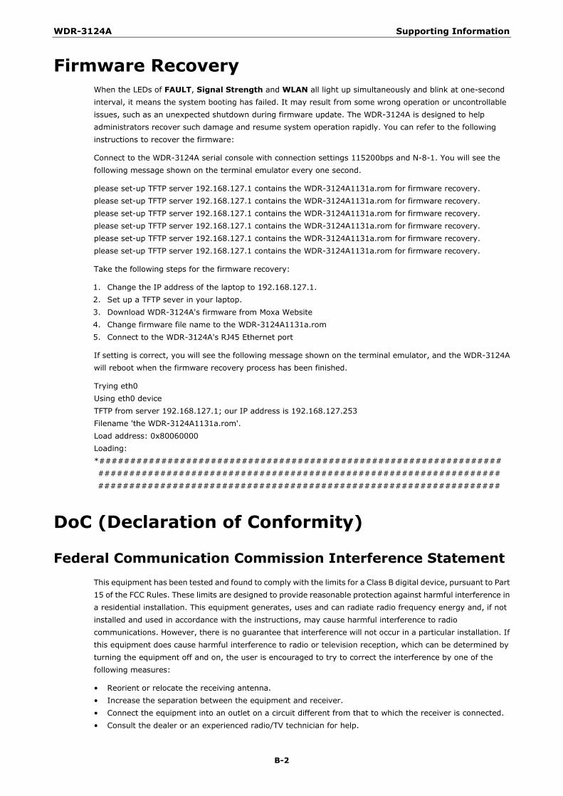
WDR-3124A Supporting Information
B-2
Firmware Recovery When the LEDs of FAULT, Signal Strength and WLAN all light up simultaneously and blink at one-second interval, it means the system booting has failed. It may result from some wrong operation or uncontrollable issues, such as an unexpected shutdown during firmware update. The WDR-3124A is designed to help administrators recover such damage and resume system operation rapidly. You can refer to the following instructions to recover the firmware:
Connect to the WDR-3124A serial console with connection settings 115200bps and N-8-1. You will see the following message shown on the terminal emulator every one second.
please set-up TFTP server 192.168.127.1 contains the WDR-3124A1131a.rom for firmware recovery. please set-up TFTP server 192.168.127.1 contains the WDR-3124A1131a.rom for firmware recovery. please set-up TFTP server 192.168.127.1 contains the WDR-3124A1131a.rom for firmware recovery. please set-up TFTP server 192.168.127.1 contains the WDR-3124A1131a.rom for firmware recovery. please set-up TFTP server 192.168.127.1 contains the WDR-3124A1131a.rom for firmware recovery. please set-up TFTP server 192.168.127.1 contains the WDR-3124A1131a.rom for firmware recovery.
Take the following steps for the firmware recovery:
1. Change the IP address of the laptop to 192.168.127.1. 2. Set up a TFTP sever in your laptop. 3. Download WDR-3124A's firmware from Moxa Website 4. Change firmware file name to the WDR-3124A1131a.rom 5. Connect to the WDR-3124A's RJ45 Ethernet port
If setting is correct, you will see the following message shown on the terminal emulator, and the WDR-3124A will reboot when the firmware recovery process has been finished.
Trying eth0 Using eth0 device TFTP from server 192.168.127.1; our IP address is 192.168.127.253 Filename 'the WDR-3124A1131a.rom'. Load address: 0x80060000 Loading: *################################################################# ################################################################# #################################################################
DoC (Declaration of Conformity)
Federal Communication Commission Interference Statement This equipment has been tested and found to comply with the limits for a Class B digital device, pursuant to Part 15 of the FCC Rules. These limits are designed to provide reasonable protection against harmful interference in a residential installation. This equipment generates, uses and can radiate radio frequency energy and, if not installed and used in accordance with the instructions, may cause harmful interference to radio communications. However, there is no guarantee that interference will not occur in a particular installation. If this equipment does cause harmful interference to radio or television reception, which can be determined by turning the equipment off and on, the user is encouraged to try to correct the interference by one of the following measures:
• Reorient or relocate the receiving antenna. • Increase the separation between the equipment and receiver. • Connect the equipment into an outlet on a circuit different from that to which the receiver is connected. • Consult the dealer or an experienced radio/TV technician for help.
WDR-3124A Supporting Information
B-3
FCC Caution: To assure continued compliance, (example – use only shielded interface cables when connecting to computer or peripheral devices). Any changes or modifications not expressly approved by the party responsible for compliance could void the user’s authority to operate this equipment. This transmitter must not be co-located or operated in conjunction with any other antenna or transmitter.
FCC Radiation Exposure Statement
This equipment complies with FCC radiation exposure limits set forth for an uncontrolled environment. This equipment should be installed and operated with a minimum distance of 20 cm between the radiator & your body.
This device complies with Part 15 of the FCC Rules. Operation is subject to the following two conditions: (1) This device may not cause harmful interference, and (2) this device must accept any interference received, including interference that may cause undesired operation.
FCC 15.407(e): Within the 5.15-5.25 GHz band, U-NII devices will be restricted to indoor operations to reduce any potential for harmful interference to co-channel MSS operations.
R&TTE Compliance Statement Moxa declares that the apparatus WDR-3124A complies with the essential requirements and other relevant provisions of Directive 1999/5/EC.
This equipment complies with all the requirements of DIRECTIVE 1999/5/CE OF THE EUROPEAN PARLIAMENT AND THE COUNCIL OF 9 March 1999 on radio equipment and telecommunication terminal equipment and the mutual recognition of their conformity (R&TTE).
The R&TTE Directive repeals and replaces in the directive 98/13/EEC (Telecommunications Terminal Equipment and Satellite Earth Station Equipment) as of April 8, 2000.
Safety
This equipment is designed with the utmost care for the safety of those who install and use it. However, special attention must be paid to the dangers of electric shock and static electricity when working with electrical equipment. All guidelines of this and of the computer manufacturer must therefore be allowed at all times to ensure the safe use of the equipment.
EU Countries Intended for Use
The ETSI version of this device is intended for home and office use in Austria, Belgium, Denmark, Finland, France (with Frequency channel restrictions), Germany, Greece, Ireland, Italy, Luxembourg, Portugal, Spain, Sweden, The Netherlands, and United Kingdom.
The ETSI version of this device is also authorized for use in EFTA member states Norway and Switzerland.
EU Countries Not Intended for Use
None.
Potential Restrictive Use
France: only channels 10, 11, 12, and 13.
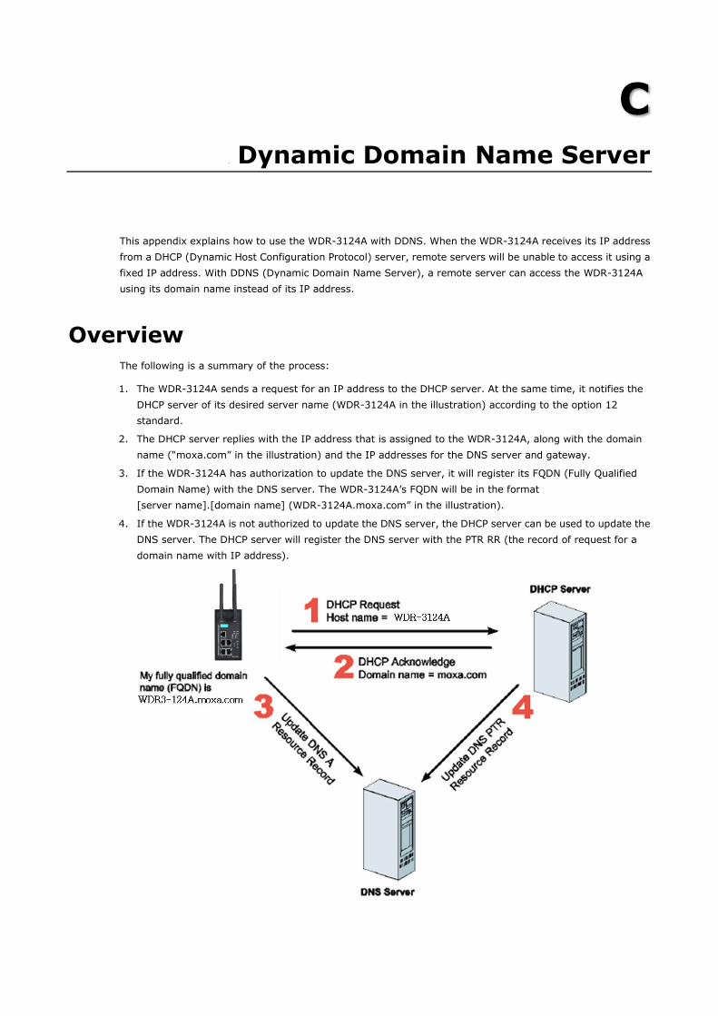
C C. Dynamic Domain Name Server
This appendix explains how to use the WDR-3124A with DDNS. When the WDR-3124A receives its IP address from a DHCP (Dynamic Host Configuration Protocol) server, remote servers will be unable to access it using a fixed IP address. With DDNS (Dynamic Domain Name Server), a remote server can access the WDR-3124A using its domain name instead of its IP address.
Overview The following is a summary of the process:
1. The WDR-3124A sends a request for an IP address to the DHCP server. At the same time, it notifies the DHCP server of its desired server name (WDR-3124A in the illustration) according to the option 12 standard.
2. The DHCP server replies with the IP address that is assigned to the WDR-3124A, along with the domain name (“moxa.com” in the illustration) and the IP addresses for the DNS server and gateway.
3. If the WDR-3124A has authorization to update the DNS server, it will register its FQDN (Fully Qualified Domain Name) with the DNS server. The WDR-3124A’s FQDN will be in the format [server name].[domain name] (WDR-3124A.moxa.com” in the illustration).
4. If the WDR-3124A is not authorized to update the DNS server, the DHCP server can be used to update the DNS server. The DHCP server will register the DNS server with the PTR RR (the record of request for a domain name with IP address).
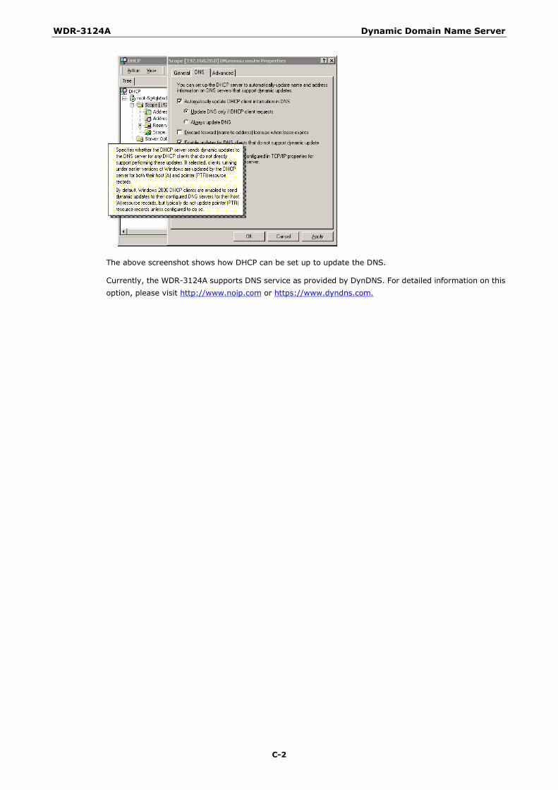
WDR-3124A Dynamic Domain Name Server
C-2
The above screenshot shows how DHCP can be set up to update the DNS.
Currently, the WDR-3124A supports DNS service as provided by DynDNS. For detailed information on this option, please visit http://www.noip.com or https://www.dyndns.com.