we make the cut - cal poly
TRANSCRIPT
EZ‐Labels Inc. | Confidential‐ No unauthorized reproduction without a written agreement
1
We Make the Cut
Sponsor: Gerald E. Finken, Clinical Supplies Management Inc.
Engineers: Nathan Cheadle [email protected] Lorne Stoops [email protected] Tony Wang [email protected] Robert Zimmerman [email protected]
Purpose: To create a die-cutting machine capable of producing pharmaceutical labels of varying size.
EZ‐Labels Inc. | Confidential‐ No unauthorized reproduction without a written agreement
2
TableofContentsIntroduction .................................................................................................................................................. 4
Background ................................................................................................................................................... 5
Objectives ..................................................................................................................................................... 8
Design Development ................................................................................................................................... 11
Description of Final Concept ....................................................................................................................... 15
Preliminary Testing: .................................................................................................................................... 23
Final Design ................................................................................................................................................. 24
Cutting Area: ........................................................................................................................................... 25
Roller Assembly: ...................................................................................................................................... 26
Cutter Assembly: ..................................................................................................................................... 29
Short Rail Assembly ................................................................................................................................. 31
Final Assembly Components: .................................................................................................................. 32
Description of Cutting Program: ............................................................................................................. 33
Maintenance Schedule ............................................................................................................................... 34
Daily After Use: ....................................................................................................................................... 34
Weekly: ................................................................................................................................................... 34
Timeframe Unknown: ............................................................................................................................. 34
Design Verification and Testing .................................................................................................................. 36
Product Realization ..................................................................................................................................... 39
Management Plan ....................................................................................................................................... 42
Conclusion and Recommendations ............................................................................................................ 44
APPENDICES: ............................................................................................................................................... 45
Appendix A: QFD, Decision Matrix, and Test Results .............................................................................. 46
Quality Function Deployment Analysis ............................................................................................... 46
Decision Matrices ................................................................................................................................ 47
Cutter Testing Results ......................................................................................................................... 50
Appendix B: Drawing Packet‐ See Attached Documents ........................................................................ 51
Manufactured Parts Assembly Map: See Attached Documents ......................................................... 51
Appendix C: Vendors and Pricing ............................................................................................................ 52
Purchased Parts Cost Estimate: .......................................................................................................... 52

EZ‐Labels Inc. | Confidential‐ No unauthorized reproduction without a written agreement
3
Material Cost Estimate: ....................................................................................................................... 53
Final Order History: ............................................................................................................................. 54
Appendix D: Component Specifications .................................................................................................. 56
Solenoid Testing Results ..................................................................................................................... 56
Appendix E: Analysis Concerning Final Design ........................................................................................ 57
Appendix F: Project Planning .................................................................................................................. 58
Appendix G: Wiring Diagram .................................................................................................................. 59
Appendix H: Mechatronics Code ............................................................................................................ 60

EZ‐Labels Inc. | Confidential‐ No unauthorized reproduction without a written agreement
4
Introduction Team EZ-Label has been formed to provide an innovative solution that satisfies the need of Mr. Gerald E. Finken of Clinical Supplies Management (CSM) Inc. to print clinical trial prescription drug labels on demand. Printing labels on demand drastically differs from the current method of producing pharmaceutical trial labels and requires a machine that will assist in streamlining this new process. The final product will have, but is not limited to, the following basic characteristics:
Print and cut labels of varying size
Integrate the printing and cutting operation into a single device
Be Portable
The original project proposal was to design and build a thermal transfer printer, label cutter, and auto-inspector for making labels that are used on prescription drugs in clinical trials. After a meeting with the sponsor and project advisor, it was decided that Team EZ Labels will focus on designing a label cutter that can quickly cut labels of varying size.
Through testing and analysis it was determined that the most effective design will use a cutting wheel that is able to move along an x and y axis. This decision was made by testing different cutting methods, and finding that the wheel cutter had the largest tolerance of acceptable applied force for cutting through the label and not the backing. It also holds other advantages over a laser and drag blade. With the wheel there is no need for ventilation of the cutting space, or the possibility to catch and tear the label stock. The x-y axis motion was chosen because this method offers the capability of cutting complex shapes with a reliable mechanism design. Ultimately, this product will reduce the time and resources required to produce clinical trial labels, resulting in significant savings for CSM Inc.
Figure 1. Solidworks model of Final Design

EZ‐Labels Inc. | Confidential‐ No unauthorized reproduction without a written agreement
5
Background Currently labels for clinical trials are printed on pre-cut label rolls weeks before patients have signed up for a trial. For each different sized label a different roll of pre-cut label stock needs to be purchased. Each clinical trial will require different sized labels, and each trial package requires different sized labels for the different items in a package. The traditional approach to satisfying clinical trial orders has been to produce all the prescription packages before the trial begins and then distribute the medications as individuals sign up for the trial. This requires warehousing the prescription drugs and printing more labels than will actually be used. This warehousing and wasted product is costly. The process of printing the labels is also very time intensive when each different size of label needs to be loaded into the printer separately.
Many of the regulations for prescription labeling come directly from the Federal and Drug Administration (FDA). These regulations require that the label clearly convey prescription information even after exposure to water, blood, alcohol, or rubbing. The labels must also be printed in color to provide clear instructions. The FDA also requires 200% inspection of the labels to make sure that all labels are printed correctly and accurately. Another important requirement for labels used in clinical trials is to make sure that there is no visible difference between drug kits. This is to make sure that the trial stays blind, meaning that the patient cannot determine whether the medication is a placebo or not.
Specific FDA regulations relevant to drug labeling include:
21 CFR 201 (FDA, 2012)
Includes all FDA regulations that are directly related to labeling Almost all regulations in regards to content of label, not label itself
21 CFR 201.56 (FDA, 2012)
Summary for the safe and effective use of the drug Informative and accurate Not promotional, false, or misleading No implied claims or suggestions for use if evidence of safety or effective is lacking Based whenever possible on data derived from human experience
21 CFR 210 (FDA, 2012)
Overviews good manufacturing practice regulation and investigational new drugs Stage 1 clinical trial generally includes no more than 80 subjects Stage 2 & 3 trials can include substantially more subjects Stage 2 & 3 allow drugs to be used for treatment
EZ‐Labels Inc. | Confidential‐ No unauthorized reproduction without a written agreement
6
21 CFR 210.1 (FDA, 2012)
Status of current good manufacturing practice regulations
21 CFR 211.63 – 211.68 (FDA, 2012)
Overviews the needs and the manufacturing requirements for equipment used to make labels in clinical trials
21 CFR 211.122 – 211.130 (FDA, 2012)
Reviews the practices that should be followed for the packaging and shipping of prescription of drugs.
21 CFR 211.184 (FDA, 2012)
Overviews the requirements for recording and reporting shipments and packages in the prescription drug market.
21CFR Part 11 (FDA, 2012)
Overviews the need for change tracking in any computer programs that are used in conjunction with the manufacture of prescription drugs
There exist three major methods that are suitable for cutting prescription labels. The first and most common method currently in use is a stamping die. The die can be flat and stamp the label by moving vertically (Platen Press); or the die profile can be contoured over a cylinder and the labels are cut as they feed under this roller (Rotary Die Cutter). Both of these types of die cutting use a machined die to cut out hundreds of thousands of labels to the exact same size. This is economical for mass production, but can take hours to reset the machine with a different die, and cut a different size label. The equipment and dies are also extremely large and expensive. Once a die is machined it is only capable of cutting a single design, and thus is not versatile enough to meet the needs of CSM’s on demand process.
The second method uses a computer guided blade to cut out a shape. This blade is able to cut at a specific depth so the label backing can be peeled off and removed. This method allows many unique shapes to be cut, but does not allow for as large a scale of production as stamping dies. These machines are complex, and in order to provide the greatest degree of versatility, they are very large in order to provide more cutting area. Individual sheets must be placed into the cutting area for each run. This method is an applicable cutting method to satisfy the needs of CSM, but a more unique device that is specifically tailored to smaller, roll fed material is needed.
The third major method currently on the market that could cut out prescription labels is a laser cutter. The laser cutter runs at about the same speed and accuracy as the blade cutter, but

EZ‐Labels Inc. | Confidential‐ No unauthorized reproduction without a written agreement
7
has the advantage of not requiring the cutter to be replaced. Depth of cut is easily changed by adjusting the power setting of the laser. However, the laser system is more expensive than the drag knife blade system, and also requires ventilation of the cutting area; therefore a laser solution cannot be portable if it is to require a ventilation system designed for a specific room or building.
Table 1. Pertinent data of commercial products
ROLAND SV‐15 Universal VLS 3.50 KAMA ProCut74
Type Desktop Vinyl Cutter Laser Cutter Platen Press
Max Cutting Area 13.25" x 39.25" 24" x 12" 23.6" x 29.1"
Cutting Speed 0.44 ‐ 3.88 in/min Not Listed 5000 sheets/hr
Max Material Thickness 0.004 in 50 W laser max 1.8 mm
Weight (lb) 7.3 95 6000 estimated
Cost (USD) 1095 6000 20000+

EZ‐Labels Inc. | Confidential‐ No unauthorized reproduction without a written agreement
8
Objectives Our team is working to design a device that will be able to accurately cut prescription drug labels of various sizes. The labels will first be thermal transfer printed on a continuous roll feed of label stock, and then be fed into the label cutter. The EZ Labels team worked with Mr. Finken to define the scope of this project and understand what capabilities the final design should have.
It is understood that this prescription label die cutter will meet the following requirements:
Functional Performance Quickly satisfy orders Accurately cut labels Be able to perforate label and backing Cut from a continuous roll feed of label stock Cut different label materials Cut label stock of varying thickness Cut variably sized rectangular labels Be reliable
Human Interaction No open access to cutting device No toxic exposure to user Include handholds for easy lifting and relocation Minimal user involvement Can be operated by one person
Physical Requirements Be portable Fit on service cart Able to roll through a door Operate in an office space
Life Cycle Concerns Device should be highly serviceable, have easy access to critical components Device should be recyclable at end of operating life
Resource Concerns Interface with printer and computer by a common file type Function with label stock at least six inches wide.
EZ‐Labels Inc. | Confidential‐ No unauthorized reproduction without a written agreement
9
Manufacturing Concerns All parts can be manufactured without CNC control Not require components to be welded Have Readily available parts
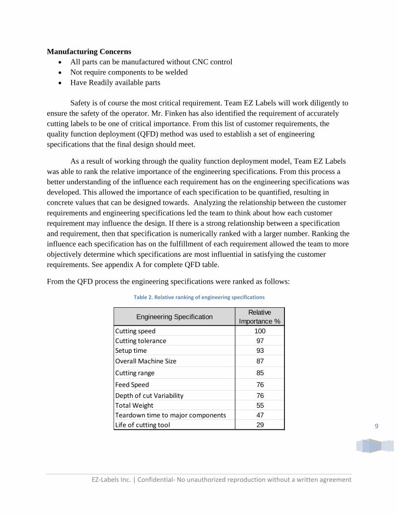
Safety is of course the most critical requirement. Team EZ Labels will work diligently to ensure the safety of the operator. Mr. Finken has also identified the requirement of accurately cutting labels to be one of critical importance. From this list of customer requirements, the quality function deployment (QFD) method was used to establish a set of engineering specifications that the final design should meet.
As a result of working through the quality function deployment model, Team EZ Labels was able to rank the relative importance of the engineering specifications. From this process a better understanding of the influence each requirement has on the engineering specifications was developed. This allowed the importance of each specification to be quantified, resulting in concrete values that can be designed towards. Analyzing the relationship between the customer requirements and engineering specifications led the team to think about how each customer requirement may influence the design. If there is a strong relationship between a specification and requirement, then that specification is numerically ranked with a larger number. Ranking the influence each specification has on the fulfillment of each requirement allowed the team to more objectively determine which specifications are most influential in satisfying the customer requirements. See appendix A for complete QFD table.
From the QFD process the engineering specifications were ranked as follows:
Table 2. Relative ranking of engineering specifications
Engineering SpecificationRelative
Importance %
Cutting speed 100
Cutting tolerance 97
Setup time 93
Overall Machine Size 87
Cutting range 85
Feed Speed 76
Depth of cut Variability 76
Total Weight 55
Teardown time to major components 47
Life of cutting tool 29

EZ‐Labels Inc. | Confidential‐ No unauthorized reproduction without a written agreement
10
The final design for this project should meet a set of both Quantitative and Qualitative requirements. Qualitative requirements pertain to certain characteristics the final design must have. The quantitative requirements are specific values that the final design must meet with regard to performance, operation, and physical constraints.
Qualitative Requirements
Perforates Label No open access to cutting device No Toxic exposure to user Includes hand holds for easy lifting and relocation Recyclable Interface with printer using a common file type All parts can be manufactured without CNC control Not require components to be welded
Quantitative Specifications
Total Weight: 50lbs maximum
Feed Speed: 2.25 in/min minimum
Cutting Speed: 17 in/min minimum
Cut rounded corners of 0.125 inch radius minimum
Cutting Tolerance:
o Size of Rectangle ±0.031 in o Location of Text Relative to Label Edge ±0.031 in o Perpendicularity of Label Edges 0.040 in
o Depth of Cut .. in
Label Thickness Range: 0.002-0.005 inches Overall Machine Size: 43 inches long, 25 inches wide, 24 inches tall maximum
Cutting Range: 9 inches wide, 20 inches long Setup Time: 10 minutes Teardown Time to Major Components: 15 minutes Life of Cutting Tool: 80000 inches
EZ‐Labels Inc. | Confidential‐ No unauthorized reproduction without a written agreement
11
DesignDevelopment Over the course of several meetings with Mr. Finken, a set of requirements were established that the sponsor would like the product to satisfy. Once the requirements were established, further research was performed to narrow down possible technologies currently on the market that would be influential to the project design. A number of conceptual designs were conceived and analyzed to determine which best satisfies the need of CSM. At this point in the design process the EZ label team has narrowed the proposed ideas down to a single concept model that should effectively satisfy CSM’s need for a variable label cutter.
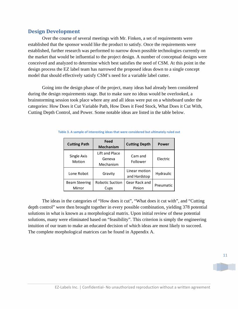
Going into the design phase of the project, many ideas had already been considered during the design requirements stage. But to make sure no ideas would be overlooked, a brainstorming session took place where any and all ideas were put on a whiteboard under the categories: How Does it Cut Variable Path, How Does it Feed Stock, What Does it Cut With, Cutting Depth Control, and Power. Some notable ideas are listed in the table below.
Table 3. A sample of interesting ideas that were considered but ultimately ruled out
The ideas in the categories of “How does it cut”, “What does it cut with”, and “Cutting depth control” were then brought together in every possible combination, yielding 378 potential solutions in what is known as a morphological matrix. Upon initial review of these potential solutions, many were eliminated based on “feasibility”. This criterion is simply the engineering intuition of our team to make an educated decision of which ideas are most likely to succeed. The complete morphological matrices can be found in Appendix A.
Cutting PathFeed
MechanismCutting Depth Power
Single Axis
Motion
Lift and Place
Geneva
Mechanism
Cam and
FollowerElectric
Lone Robot GravityLinear motion
and HardstopHydraulic
Beam Steering
Mirror
Robotic Suction
Cups
Gear Rack and
PinionPneumatic

EZ‐Labels Inc. | Confidential‐ No unauthorized reproduction without a written agreement
12
Certain ideas were eliminated for the following reasons:
The use of lasers as a cutting tool was ruled out due to the requirement for ventilation. The device could not satisfy the requirement for portability if the room in which it would operate requires air ducting to the outdoors.
Stamping blades were ruled out as a cutting tool due to the inability of pre-formed blades to cut custom complex shapes.
The use of a stationary cutter head was ruled out because this method would require the label to move in two axes. A continuous label feed is only suited to move along the feed axis.
Cutters that exclusively move in one axis cannot be used to cut rounded corners.
A small blade that repeatedly stabs to cut small sections as it moves along the cut path would provide a more ragged cut and also be less reliable due to the high number of stabbing cycles.
A robotic arm to control the cutting path would require the system to operate in more complicated polar coordinates. Deflection at the end of the arm is also an important factor when a very precise depth of cut is required.
Controlling the depth of cut by moving the label up and down would be more complicated than moving the cutter head.
Controlling the depth of cut by inserting different sized blades into the device would not offer the capability of lifting the cutter up to create perforations.
After eliminating some of the ideas in each category, the matrix results were significantly narrowed down to 14 feasible concepts that were then more closely investigated.

EZ‐Labels Inc. | Confidential‐ No unauthorized reproduction without a written agreement
13
Table 4. Decision matrix ranking of feasible concepts
For each concept design a score between 1 to 10 was given in categories of Reliability, Versatility, Safety, and Reparability. The score for each design was determined by setting the score to 5 as default and adding or subtracting points based on each defining characteristic.
For reliability- hardstops, wheel cutter, and cartesian coordinates were given +1 while actuator and label feed were given -1. Hardstops were seen as more reliable because the height would be extremely consistent assuming it is made out of hard enough material. A Wheel cutter is less likely to tear the label and deemed safer than a drag knife. Actuators were less reliable because it is harder to control its motion compared to a cam or hardstop. Label feed was also deemed less reliable because it would involve more and bigger moving parts to function properly.
For the versatility category- the cam, single blade, and actuator were given +1 and hard stop was given a -1. Both Cam and actuator received a +1 because unlike hard stops, a continuous range of depths can be cut. Hard stop received a -1 since it can only cut at one specific depth per hard stop. A single blade design was considered more versatile because of its ability to cut sharper corners than cutting wheel.
For safety- label feed, single blade, and solenoid were all given -1. By feeding the label it creates more moving parts outside of the cutting area that a worker can get articles caught in. The blade was deemed less safe than the cutting wheel so it received a -1, while cutting wheel got a +1. Solenoid was also given a -1 because it produces an abrupt force creating a potential pinch hazard.
Reliability
30%
Versatility
25%
Safety
32%
Repairable
13%
Ideas 10 Reliable 10 simple 10 safe 10 easy
Cam; Cartesian CS; Single Blade 6 7 5 4 5.67
Cam; Cartesian CS; Wheel Cutter 7 6 6 4 6.04
Cam; Move Label Feed Axis; Single Blade 4 7 5 4 5.07
Cam; Move Label Feed Axis; wheel Cutter 5 6 5 4 5.12
Hardstop; Solenoid; Cartesian CS; Single Blade 7 5 5 6 5.73
Hardstop; Solenoid; Cartesian CS; Wheel Cutter 8 4 5 6 5.78
Hardstop; Solenoid; Move Label Feed Axis; Single Blade 5 5 5 6 5.13
Hardstop; Solenoid; Move Label Feed Axis; Wheel Cutter 6 4 5 6 5.18
Actuator; Cartesian CS; Single Blade 5 7 5 5 5.5
Actuator; Cartesian CS; Wheel Cutter 6 6 6 5 5.87
Actuator; Move Label Feed Axis; Single Blade 3 7 5 5 4.9
Actuator; Move Label Feed Axis; Wheel Cutter 5 6 5 5 5.25
Applied Force; Cartesian CS; Wheel Cutter 9 8 5 5 6.95
Applied Force; Move Label Feed Axis; Wheel Cutter 7 6 5 5 5.85
Total

EZ‐Labels Inc. | Confidential‐ No unauthorized reproduction without a written agreement
14
The final category was reparability. Hard stops were given a +1 because it is an extremely simple design and would be easily replaced. Cam was given a -1 because it involves more unique moving parts which would make repairing/replacement more complex.
Each category was then weighted, with safety being the highest at 0.32. Reliability was given a 0.30 because in the interest of productivity the final device should not need to be constantly adjusted and repaired. Versatility was given a 0.25 because a major point that the sponsor made was that the product should anticipate future needs of CSM and be capable of satisfying future demands. This means creating a device that is able to cut labels of different thicknesses, stock of different widths, and cut complex shapes. Reparability was rated 0.13 because if the product is reliable then it would not require much repair. Also the product will be designed with easily acquired parts which should make finding replacement parts simpler.
Table 5. Top 3 concepts gleaned from matrix ranking
From these results it is easy to see that Cartesian coordinates and cutting wheel were the best method. To determine whether applied force, cam, actuator, or even hard stops would be the best method some testing was performed. We took force measurements with two different cutting wheels to see what range of force would provide an acceptable cut. From our tests it was found that the actuator or cam must be able to position the cutter with a dimensional tolerance of
.. in, while the applied force method allows for a tolerance of ±0.5 lbs. The tolerance with
respect to force is a much easier design target to achieve.
All three ideas use the Cartesian coordinate system and cutting wheel. This method would allow the cutting wheel to move along two perpendicular axes simultaneously providing the ability to cut labels of any shape.
Top 3 Results Score
Applied Force; Cartesian CS; Wheel Cutter 6.95
Cam; Cartesian CS; Wheel Cutter 6.04
Actuator; Cartesian CS; Wheel Cutter 5.87
EZ‐Labels Inc. | Confidential‐ No unauthorized reproduction without a written agreement
15
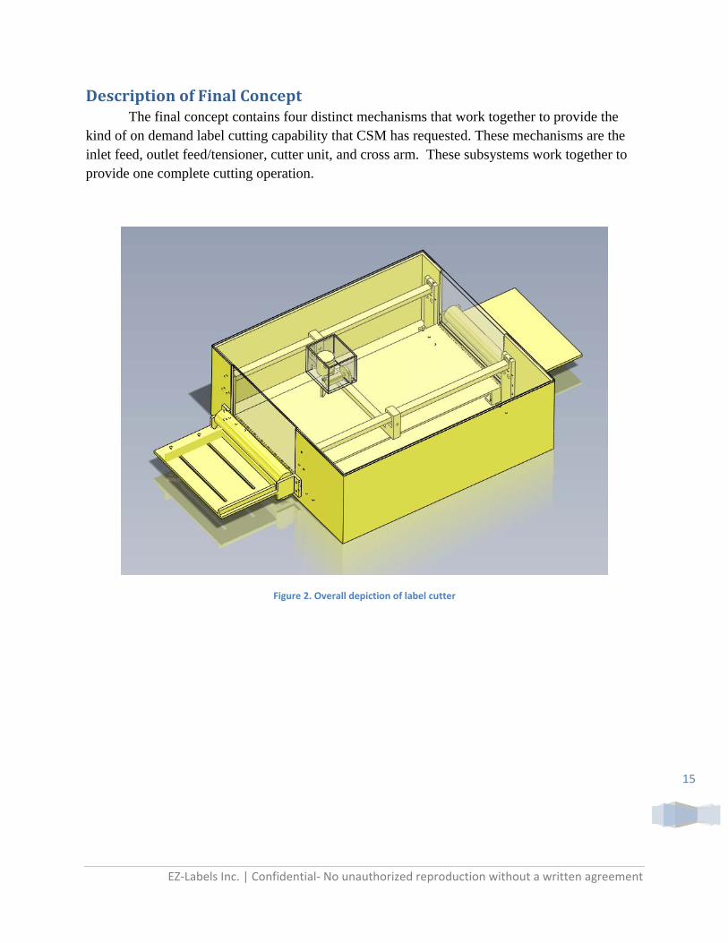
DescriptionofFinalConcept The final concept contains four distinct mechanisms that work together to provide the kind of on demand label cutting capability that CSM has requested. These mechanisms are the inlet feed, outlet feed/tensioner, cutter unit, and cross arm. These subsystems work together to provide one complete cutting operation.
Figure 2. Overall depiction of label cutter
EZ‐Labels Inc. | Confidential‐ No unauthorized reproduction without a written agreement
16
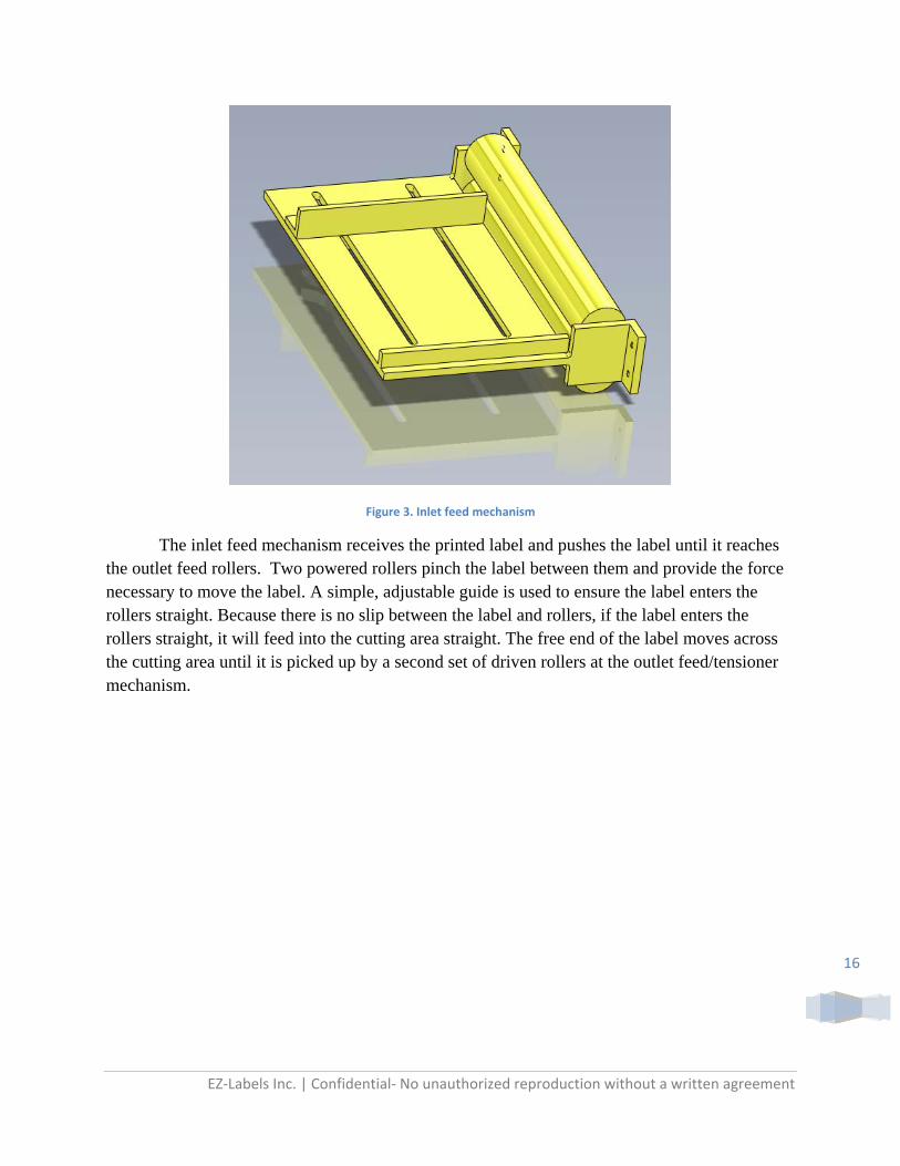
Figure 3. Inlet feed mechanism
The inlet feed mechanism receives the printed label and pushes the label until it reaches the outlet feed rollers. Two powered rollers pinch the label between them and provide the force necessary to move the label. A simple, adjustable guide is used to ensure the label enters the rollers straight. Because there is no slip between the label and rollers, if the label enters the rollers straight, it will feed into the cutting area straight. The free end of the label moves across the cutting area until it is picked up by a second set of driven rollers at the outlet feed/tensioner mechanism.

EZ‐Labels Inc. | Confidential‐ No unauthorized reproduction without a written agreement
17
Figure 4. Outlet feel/tensioner mechanism
The second set of rollers at the outlet is also driven so as to automatically pick up the free end of the label after it crosses the cutting area. Upon reaching the second set of rollers, both sets will stop feeding and no longer be able to rotate. At this point the second roller set will move vertically downwards to tension the label over the cutting surface. It is important to secure the label flat over the cutting surface to provide an accurate cut. The next step is to locate the label text around which label shapes must be cut.
Locating the label text relative to the coordinate system of the label cutter is critical in order to accurately cut shapes around the text. To accomplish this, a specific grouping of black dots will be printed near the edge of the label stock. These dots will not appear on the final prescription label product, they are merely printed in unused space on the label stock. An optical sensor on the cutter unit will “find” these black dots to establish the location of the label text based on the information provided by the computer file containing the label text information and formatting.
In summary up to this point this point the label has been fed into the die cutter, tensioned over the cutting surface, and the location of the label text has been identified by the sensor. Now the labels can be cut by moving the cutter unit over the cutting surface and pushing the cutting wheel down using a solenoid.

EZ‐Labels Inc. | Confidential‐ No unauthorized reproduction without a written agreement
18
Figure 5. Cross arm
The cross arm is a simple mechanism. It too uses a rack and pinion gear system driven by a motor with an optical encoder. The arm itself serves as a track over which the cutter unit can move. The cross arm itself moves on a track parallel to the label feed direction. The optical encoder again serves to accurately locate the position of the cutter along this second axis of motion. The cross arm and cutter unit move together to provide full motion control capable of tracing any shape. When the labels are finished being cut, the outlet rollers will move vertically upward to release the tension on the label, and both roller sets will feed the label out of the device. This entire operation is expected to take no more than five minutes.

EZ‐Labels Inc. | Confidential‐ No unauthorized reproduction without a written agreement
19
Figure 6. Cutter unit
The cutter unit contains 3 major components. First is the cutter itself which has been previously described. The cutter is a sharpened wheel that is free to swivel, and is pushed onto the label with a specific force by use of a solenoid. The second component is the optical sensor that is used to locate the label text. Third is a motor which uses a rack and pinion gear system to move the cutter unit back and forth along the cross arm. The position of the cutter unit along the cross arm can be precisely established through the use of an optical encoder on the motor. The optical encoder will provide a signal that can be used to compute the number of degrees of revolution the motor has turned. This information will be used to calculate the position of the cutting wheel along one axis. The cross arm itself also moves to provide motion along a second axis.

EZ‐Labels Inc. | Confidential‐ No unauthorized reproduction without a written agreement
20
The cutting wheel is a wheel where the outer edge is sharpened into a blade. The blade is then secured onto an axle, and by pushing and rolling the blade along the label, is able to cut through it. The blade angle on the wheel is important in determining how much force must be applied to completely cut through a label. Out of the two cutting blades that were tested, the glass cutter blade was found to be superior to the paper cutter. The glass cutter uses a durable tungsten carbide cutting wheel. The wheel is of a small diameter making it better suited for cutting rounded corners. The blunter blade angle also allows for a greater range of applied force to provide a suitable cut.
Figure 7. Offset cutting wheel design (Appendix A‐1)
EZ‐Labels Inc. | Confidential‐ No unauthorized reproduction without a written agreement
21
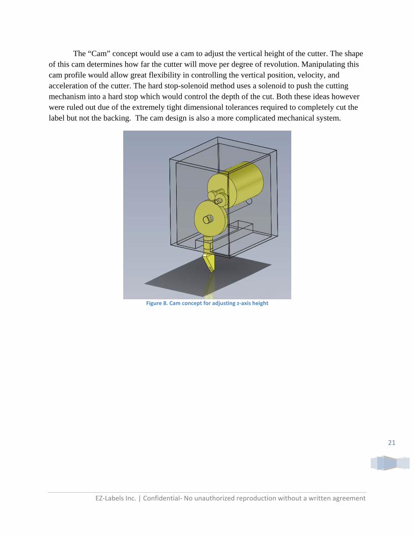
The “Cam” concept would use a cam to adjust the vertical height of the cutter. The shape of this cam determines how far the cutter will move per degree of revolution. Manipulating this cam profile would allow great flexibility in controlling the vertical position, velocity, and acceleration of the cutter. The hard stop-solenoid method uses a solenoid to push the cutting mechanism into a hard stop which would control the depth of the cut. Both these ideas however were ruled out due of the extremely tight dimensional tolerances required to completely cut the label but not the backing. The cam design is also a more complicated mechanical system.
Figure 8. Cam concept for adjusting z‐axis height
EZ‐Labels Inc. | Confidential‐ No unauthorized reproduction without a written agreement
22
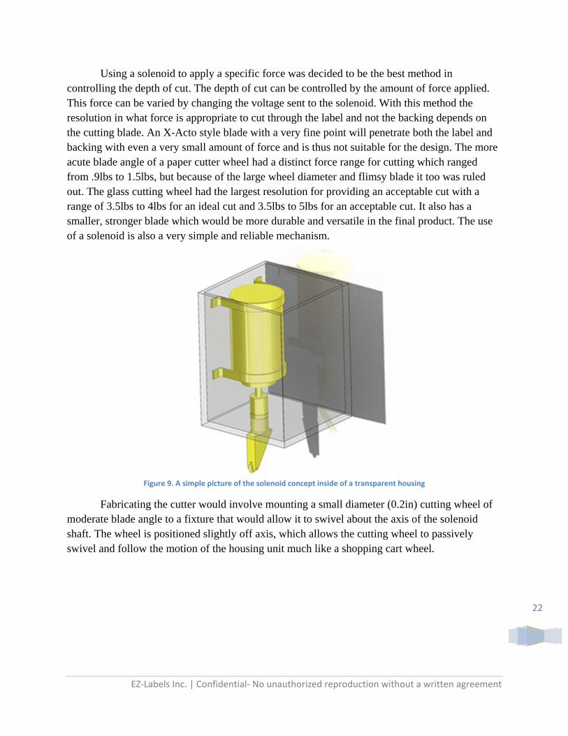
Using a solenoid to apply a specific force was decided to be the best method in controlling the depth of cut. The depth of cut can be controlled by the amount of force applied. This force can be varied by changing the voltage sent to the solenoid. With this method the resolution in what force is appropriate to cut through the label and not the backing depends on the cutting blade. An X-Acto style blade with a very fine point will penetrate both the label and backing with even a very small amount of force and is thus not suitable for the design. The more acute blade angle of a paper cutter wheel had a distinct force range for cutting which ranged from .9lbs to 1.5lbs, but because of the large wheel diameter and flimsy blade it too was ruled out. The glass cutting wheel had the largest resolution for providing an acceptable cut with a range of 3.5lbs to 4lbs for an ideal cut and 3.5lbs to 5lbs for an acceptable cut. It also has a smaller, stronger blade which would be more durable and versatile in the final product. The use of a solenoid is also a very simple and reliable mechanism.
Figure 9. A simple picture of the solenoid concept inside of a transparent housing
Fabricating the cutter would involve mounting a small diameter (0.2in) cutting wheel of moderate blade angle to a fixture that would allow it to swivel about the axis of the solenoid shaft. The wheel is positioned slightly off axis, which allows the cutting wheel to passively swivel and follow the motion of the housing unit much like a shopping cart wheel.

EZ‐Labels Inc. | Confidential‐ No unauthorized reproduction without a written agreement
23
PreliminaryTesting: Testing was done to determine the best method of cutting through the label stock. Three different styles of cutting blades were tested:
“Olfa” 18 mm Rotary Cutter
“Red Devil” Glass Cutter
“X-Acto” knife.
These three blades were tested by applying a range of forces and analyzing the quality of the cut. The force required to move the cutter over the label was also measured for an applied force that provided a suitable cut.
A few main points were gleaned from this testing. The first is that using a force to determine the depth of cut works well for the two rotary blades, but is ineffective for use with the “E-Xacto” Blade. The second is that the glass cutter provided the largest range of force that cut the label without cutting the backing. Finally, the dimensional tolerance for using an x-acto style
blade to provide a clean cut is a slim .. in, meaning that the label must be cut entirely
through (-0.000) and the backing can be cut into up to +0.001 inches.
The solenoid that will be used in the final design was also tested. Though the manufacturer provides force curves, EZ Label wanted to test the solenoid that was received to verify with the manufacturers data. The results from testing matched closely with the manufacturer’s data. By testing the solenoid, the team was also able to determine the optimal operating point of the solenoid. This is extremely important due to the fact that many other dimensions of the cutter will be based on the operating stroke length of the solenoid. With an appropriate stroke length chosen, dimensions can be finalized and so production can begin.
Another important factor that will need to be tested is the ability of the various cutting wheels to take corners. This will allow us to determine the minimum cut radius that can be done with the machine. It still needs to be determined how accurately an off axis following cutting wheel follows the path of the solenoid axis.
Also, a system that optically registers the location of the label text on the cutting plane must still be designed and tested. First the location of the label text must be precisely defined, only then the rest of the system accurately cut the label shape relative to the text location.
EZ‐Labels Inc. | Confidential‐ No unauthorized reproduction without a written agreement
24
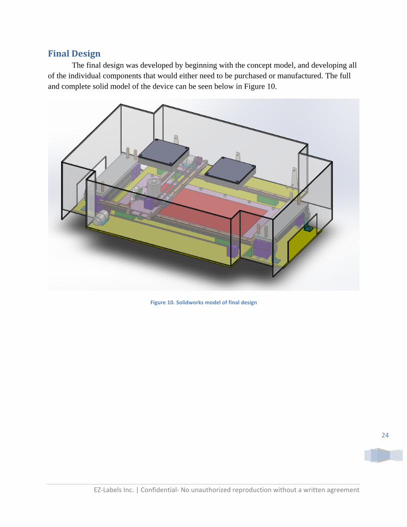
FinalDesign The final design was developed by beginning with the concept model, and developing all of the individual components that would either need to be purchased or manufactured. The full and complete solid model of the device can be seen below in Figure 10.
Figure 10. Solidworks model of final design

EZ‐Labels Inc. | Confidential‐ No unauthorized reproduction without a written agreement
25
CuttingArea:
Figure 11. Cutting surface as mounted
As shown in Figure 11, a replaceable cutting surface will be attached to the main plate structure. This surface must be hard to provide a clean cut by the cutting wheel and so 0.125 inch aluminum plate is used. The aluminum plate will become scratched by the tungsten carbide cutting wheel when the label backing is cut clean through, but since a majority of cuts will not cut through the backing, the cutting surface should last a while before needing to be replaced. The exact amount of time is yet unknown, but will depend on the frequency of through cuts and the operation time of the label cutter. Even when the cutting surface is scratched by through cuts, these scratches are not generally deep enough to significantly affect the quality of future cuts.
Regardless, this cutting surface is designed to be easily replaceable. When the label cutter is initially constructed the guide fence will be precisely located and should not be moved or removed. For this reason, one edge of the cutting surface will be secured by being slid into a 0.125 inch gap under the fixed fence. The other edge will be bolted to the main plate. The fence will be used to align the label when a new label roll is being loaded through the device. This method defines the location of the label in one axis as well as ensures the label is perpendicular to the rollers for proper feeding.
EZ‐Labels Inc. | Confidential‐ No unauthorized reproduction without a written agreement
26
RollerAssembly:
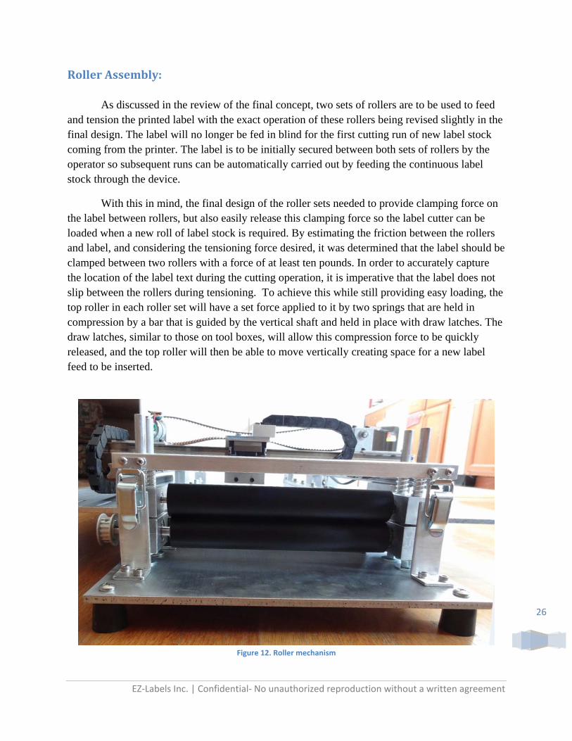
As discussed in the review of the final concept, two sets of rollers are to be used to feed and tension the printed label with the exact operation of these rollers being revised slightly in the final design. The label will no longer be fed in blind for the first cutting run of new label stock coming from the printer. The label is to be initially secured between both sets of rollers by the operator so subsequent runs can be automatically carried out by feeding the continuous label stock through the device.
With this in mind, the final design of the roller sets needed to provide clamping force on the label between rollers, but also easily release this clamping force so the label cutter can be loaded when a new roll of label stock is required. By estimating the friction between the rollers and label, and considering the tensioning force desired, it was determined that the label should be clamped between two rollers with a force of at least ten pounds. In order to accurately capture the location of the label text during the cutting operation, it is imperative that the label does not slip between the rollers during tensioning. To achieve this while still providing easy loading, the top roller in each roller set will have a set force applied to it by two springs that are held in compression by a bar that is guided by the vertical shaft and held in place with draw latches. The draw latches, similar to those on tool boxes, will allow this compression force to be quickly released, and the top roller will then be able to move vertically creating space for a new label feed to be inserted.
Figure 12. Roller mechanism

EZ‐Labels Inc. | Confidential‐ No unauthorized reproduction without a written agreement
27
The outer diameter of the roller material is 1.25 inches to provide adequate spacing between the aluminum blocks at each end that support the roller shaft bearings. In the selection of the rubber material, polyurethane of 60A durometer hardness was selected. This polyurethane will provide sufficient friction between the rubber and label. 60A is a medium hardness so that deformation of the roller material will provide sufficient contact area to prevent marking and marring of the label surface. Neoprene 90A was tested but proved to be too hard and also marked the labels. Silicone was also tested and showed to have an appropriate hardness and did not mark the label, but the material did not provide enough friction between the roller and label to prevent slipping.
These rollers are secured by bearings supported in aluminum blocks that are guided by the four vertical shafts. The bottom roller in each assembly is either driven by a pulley/motor system or braked. These actions are applied to the bottom roller so that this more complicated component does not need to be moved when loading a new label roll. Due to space constraints the application of the driving or braking force needed to be applied away from the label and rubber roller. This is done outside of the space between the vertical guide shafts. It is for this reason that there exist two vertical guide shafts at each end so that the bottom roller shaft can protrude through the bearing block, between the vertical guide shafts, into the more open area to the outside of the guide shafts. Having two vertical guide shafts on each side also stiffens this cantilever structure to prevent any bending due to tensioning or the compression of the rollers. When not considering the pulley or brake, the two roller set assemblies at each end are mirror images of one another, thus reducing the number of unique parts needed.
Figure 13. Shaft Brake as assembled on roller mechanism
EZ‐Labels Inc. | Confidential‐ No unauthorized reproduction without a written agreement
28
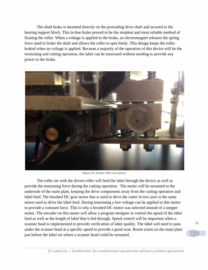
The shaft brake is mounted directly on the protruding drive shaft and secured to the bearing support block. This in-line brake proved to be the simplest and most reliable method of fixating the roller. When a voltage is applied to the brake, an electromagnet releases the spring force used to brake the shaft and allows the roller to spin freely. This design keeps the roller braked when no voltage is applied. Because a majority of the operation of this device will be the tensioning and cutting operation, the label can be tensioned without needing to provide any power to the brake.
Figure 14. Driven roller set system
The roller set with the driven roller will feed the label through the device as well as provide the tensioning force during the cutting operation. The motor will be mounted to the underside of the main plate, keeping the drive components away from the cutting operation and label feed. The brushed DC gear motor that is used to drive the cutter in two axes is the same motor used to drive the label feed. During tensioning a low voltage can be applied to this motor to provide a constant force. This is why a brushed DC motor was selected instead of a stepper motor. The encoder on this motor will allow a program designer to control the speed of the label feed as well as the length of label that is fed through. Speed control will be important when a scanner head is implemented to provide verification of label quality. The label will need to pass under the scanner head at a specific speed to provide a good scan. Room exists on the main plate just before the label set where a scanner head could be mounted.

EZ‐Labels Inc. | Confidential‐ No unauthorized reproduction without a written agreement
29
Of all the designs considered, this modular roller set design proved to be the simplest and most reliable design. The draw latches will allow the roller set to be quickly and easily unlocked. The vertical guide shafts may either be steel or aluminum depending on wear considerations, but the linear travel of the top roller is so infrequent and limited in range that either material should be sufficient. Care should be taken to keep these guide rails clean and lightly oiled. Smoothness of operation will be mostly dependent on the manufacturing tolerances of the hole diameter and location in the guide blocks to prevent binding.
CutterAssembly:
Figure 15. Overall solid model of cutter assembly
The function of this assembly is a combination of being able to apply a controlled downward force onto the cutting surface, have a free rotating cutting wheel, optical sensor to precisely determine location, and be driven on a single axis rail. Multiple iterations went into designing this part as the design was simplified and parts combined into what it is now.
EZ‐Labels Inc. | Confidential‐ No unauthorized reproduction without a written agreement
30
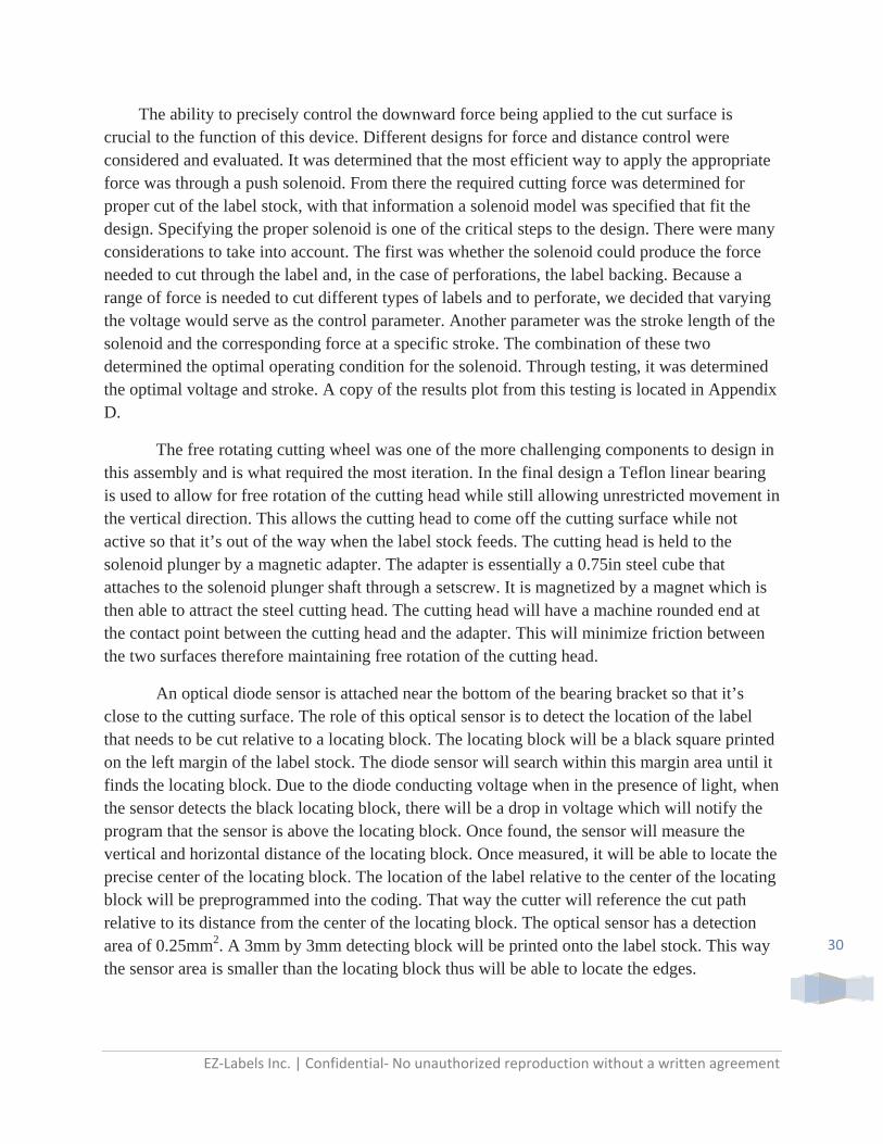
The ability to precisely control the downward force being applied to the cut surface is crucial to the function of this device. Different designs for force and distance control were considered and evaluated. It was determined that the most efficient way to apply the appropriate force was through a push solenoid. From there the required cutting force was determined for proper cut of the label stock, with that information a solenoid model was specified that fit the design. Specifying the proper solenoid is one of the critical steps to the design. There were many considerations to take into account. The first was whether the solenoid could produce the force needed to cut through the label and, in the case of perforations, the label backing. Because a range of force is needed to cut different types of labels and to perforate, we decided that varying the voltage would serve as the control parameter. Another parameter was the stroke length of the solenoid and the corresponding force at a specific stroke. The combination of these two determined the optimal operating condition for the solenoid. Through testing, it was determined the optimal voltage and stroke. A copy of the results plot from this testing is located in Appendix D.
The free rotating cutting wheel was one of the more challenging components to design in this assembly and is what required the most iteration. In the final design a Teflon linear bearing is used to allow for free rotation of the cutting head while still allowing unrestricted movement in the vertical direction. This allows the cutting head to come off the cutting surface while not active so that it’s out of the way when the label stock feeds. The cutting head is held to the solenoid plunger by a magnetic adapter. The adapter is essentially a 0.75in steel cube that attaches to the solenoid plunger shaft through a setscrew. It is magnetized by a magnet which is then able to attract the steel cutting head. The cutting head will have a machine rounded end at the contact point between the cutting head and the adapter. This will minimize friction between the two surfaces therefore maintaining free rotation of the cutting head.
An optical diode sensor is attached near the bottom of the bearing bracket so that it’s close to the cutting surface. The role of this optical sensor is to detect the location of the label that needs to be cut relative to a locating block. The locating block will be a black square printed on the left margin of the label stock. The diode sensor will search within this margin area until it finds the locating block. Due to the diode conducting voltage when in the presence of light, when the sensor detects the black locating block, there will be a drop in voltage which will notify the program that the sensor is above the locating block. Once found, the sensor will measure the vertical and horizontal distance of the locating block. Once measured, it will be able to locate the precise center of the locating block. The location of the label relative to the center of the locating block will be preprogrammed into the coding. That way the cutter will reference the cut path relative to its distance from the center of the locating block. The optical sensor has a detection area of 0.25mm2. A 3mm by 3mm detecting block will be printed onto the label stock. This way the sensor area is smaller than the locating block thus will be able to locate the edges.

EZ‐Labels Inc. | Confidential‐ No unauthorized reproduction without a written agreement
31
ShortRailAssembly
Figure 16. Short Rail Assembly
The short rail assembly involved a system comprising of two rails, two carriages, and mounting plates. The decision to use two rails was made due to the concern that mounting everything on one rail would cause the assembly to torque about the rail. With the two rail system the cutter assembly is properly supported so that there is no play in the motion of the assembly. The mounting brackets are used to mount motors, pulley blocks, and belt clamps to the assembly to move the assemblies along the rails through use of linear bearings.

EZ‐Labels Inc. | Confidential‐ No unauthorized reproduction without a written agreement
32
FinalAssemblyComponents:
Many components come together in the final assembly. The large assemblies described above are mounted, but smaller components are also involved to tie the interaction of these larger assemblies together. The same size motor is used to drive the cutter along the two axes as well as feed the label. The cutter assembly and short rail assembly are clamped to the timing belts that are driven by the motors. Cable carriers are used to manage the wiring while the cutter moves so the device does not become entangled and wires do not get caught on other components.
Figure 17. Solid model showing how the short rail assembly is connected to the timing belt as well as the cable management system
The clear acrylic cover serves as a shield to all moving parts while still allowing the operator to see what is going on. Computer fans have been mounted to the cover to keep the motors and solenoids cool. These filtered fans pull air out of the case. A computer power supply will be used to convert the 120V AC power from a wall outlet to the various voltages that the cutter will operate off of.

EZ‐Labels Inc. | Confidential‐ No unauthorized reproduction without a written agreement
33
A microcontroller and motor drivers will be used to control the motors and solenoid. The microcontroller will be capable of providing proportional, integral, and derivative control and supply a pulse width modulated signal to the motor driver. These electronics will allow the microcontroller to govern both the speed and direction of the motors. Depending on the microcontroller, separate encoder counter chips may need to be purchased to count the signal from the optical encoder used in each motor. These electronics will be mounted on the front of the main base plate to allow easy access during the prototyping phase. If desired the cover can easily be lifted up to provide full access to all components of the label cutter.
DescriptionofCuttingProgram:
What follows is a rough outline of how the cutting operation will be carried out. Upon startup, the cutter unit will move towards a corner of the cutting area on the outlet feed side. A rough registration of the cutter location will be established using limit switches. The cutter will then move a roughly an inch towards the inlet feed side. The label will then be fed through until a registration mark is picked up by the optical sensor on the cutter unit. If no registration mark is identified after 24 inches of label has been fed through, the feed will stop and an error will be displayed. When the registration mark is identified, the inlet feed roller set will lock and the label will be tensioned over the cutting area. At this point more care will be taken to precisely locate the registration mark. Once the location of the text is identified, the cutter unit will begin to carry out the prescribed cutting path. After this is complete the cutter will drive itself back to the corner until the limit switches are tripped, and the entire feeding/locating operation will be carried out again.

EZ‐Labels Inc. | Confidential‐ No unauthorized reproduction without a written agreement
34
MaintenanceSchedule
DailyAfterUse:1. Wipe down rails using a rag/paper towel oiled with WD-40 (QTY 4) 2. Wipe down the cutting surface with denatured alcohol (QTY 1) 3. Wipe down the rollers with denatured alcohol (QTY 4)
Weekly:1. Clean and oil vertical shafts for roller sets. (QTY 8)
a. Remove the roller compression bar, springs, and top roller. b. Wipe down the vertical shafts using a rag/paper towel oiled with WD-40. c. Reassemble top roller, springs, and compression bar.
Note: Be sure to reassemble the top roller so the markings on the bearing blocks match up. Bearing blocks, and the side of the compression bar marked P/B should be reassembled so that these markings are on the same side as the Pulley/Brake.
2. Lubricate linear bearings (QTY 4) a. Remove the set screw on the end of the linear bearing using a 1.5mm hex wrench.
Note: There is a set screw on both ends of the linear bearing. Either will suffice. b. Using a can of WD-40 with straw attached, spray oil into the set screw hole. c. Reinstall set screw such that the screw is flush with the outside of the linear bearing. d. Wipe down rail to remove excess oil.
3. Lubricate cutter tool and solenoid block (QTY 1, QTY 1) a. Using a can of WD-40 with straw attached, spray on the cutter tool into the Teflon
bushing. b. Wipe down solenoid block using a rag/paper towel oiled with WD-40.
TimeframeUnknown:1. Polish cutting plate (QTY 1)
a. Remove the ¼-20 screws (QTY 6) securing the cutting plate to the main base plate. ! Note: Do not remove the ¼-20 (QTY 6) screws securing the guide fence to the main base plate.
b. Slide the cutting plate away from the guide fence towards the linear rail supports by at least 0.25 inches.
c. Lift the cutting plate out. d. Polish cutting surface with 200 grit sand paper to remove deep scratches.
Note: Use a sanding block or other mechanical means to ensure a flat cutting surface is maintained.
e. Polish cutting surface with 400 grit sand paper. f. Clean with denatured alcohol. g. Reinstall cutting plate by sliding the plate back under the guide fence and securing
with the ¼-20 screws (QTY 6).

EZ‐Labels Inc. | Confidential‐ No unauthorized reproduction without a written agreement
35
2. Replace cutting head (QTY 1)
a. Move the solenoid carriage over the cutting tool drop out hole located in the corner of the cutting plate nearest the roller shaft brake.
b. Move the solenoid carriage away from the drop out hole and remove the cutting tool. c. Secure the tapered end of the cutting tool in a vice using rubber pads so as not to mar
the shaft surface. d. Unscrew the replaceable cutter head and dispose of. e. Unscrew the treaded brass connector rod and dispose of. f. Thread a new brass connector rod into the tapered cutter shaft until hand tight. g. Screw on a new cutter head and tighten. h. Drop the refurbished cutting tool into the drop out hole. i. Move the solenoid carriage over the drop out hole. j. Lift the cutting tool into the linear bushing and move the carriage away from the
dropout hole.
EZ‐Labels Inc. | Confidential‐ No unauthorized reproduction without a written agreement
36
DesignVerificationandTesting
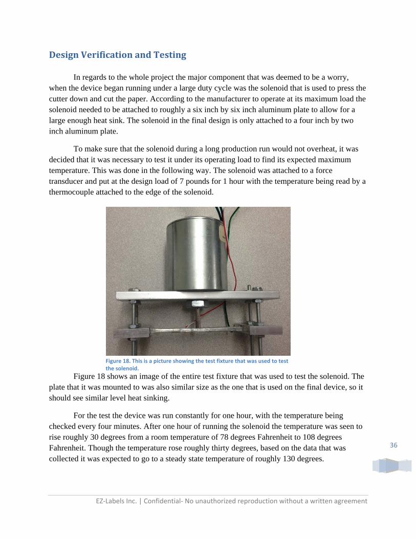
In regards to the whole project the major component that was deemed to be a worry, when the device began running under a large duty cycle was the solenoid that is used to press the cutter down and cut the paper. According to the manufacturer to operate at its maximum load the solenoid needed to be attached to roughly a six inch by six inch aluminum plate to allow for a large enough heat sink. The solenoid in the final design is only attached to a four inch by two inch aluminum plate.
To make sure that the solenoid during a long production run would not overheat, it was decided that it was necessary to test it under its operating load to find its expected maximum temperature. This was done in the following way. The solenoid was attached to a force transducer and put at the design load of 7 pounds for 1 hour with the temperature being read by a thermocouple attached to the edge of the solenoid.
Figure 18 shows an image of the entire test fixture that was used to test the solenoid. The plate that it was mounted to was also similar size as the one that is used on the final device, so it should see similar level heat sinking.
For the test the device was run constantly for one hour, with the temperature being checked every four minutes. After one hour of running the solenoid the temperature was seen to rise roughly 30 degrees from a room temperature of 78 degrees Fahrenheit to 108 degrees Fahrenheit. Though the temperature rose roughly thirty degrees, based on the data that was collected it was expected to go to a steady state temperature of roughly 130 degrees.
Figure 18. This is a picture showing the test fixture that was used to test the solenoid.

EZ‐Labels Inc. | Confidential‐ No unauthorized reproduction without a written agreement
37
These results which can be seen in Figure 19 show that there is no worry for the solenoid at these particular loads, because it stays well below a dangerous temperature level under a 100% duty cycle. The manufacturer states that a temperature above 170 degrees Fahrenheit is considered dangerous to the solenoid.
Another concern with the solenoid was that the manufacturer warned that as temperature increases the force output of the solenoid can tend to decrease. As can be seen in Figure 20 under the temperatures seen in this loading condition the force output of the solenoid is reasonably constant.
Figure 20. The results of the force output of the solenoid relative to its temperature.
3.00
4.00
5.00
6.00
7.00
8.00
9.00
65 75 85 95 105 115
Force (lb)
Temperature (F)
Run Two
Run Three
y = ‐1E‐06x2 + 0.0138x + 75.559
0
20
40
60
80
100
120
0 1000 2000 3000 4000 5000
Temperature (F)
Time (s)
Run One
Run Two
Run Three
Figure 19. The results of the temperature of the solenoid with respect to time.

EZ‐Labels Inc. | Confidential‐ No unauthorized reproduction without a written agreement
38
These results conclude that under our loading conditions of the solenoid, that there should be no worry for the solenoid overheating or having a force output that changes too much with temperature. For a complete report on all of the findings refer to Appendix D of this document.
EZ‐Labels Inc. | Confidential‐ No unauthorized reproduction without a written agreement
39
ProductRealization
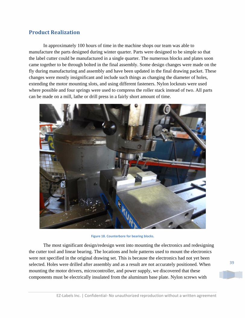
In approximately 100 hours of time in the machine shops our team was able to manufacture the parts designed during winter quarter. Parts were designed to be simple so that the label cutter could be manufactured in a single quarter. The numerous blocks and plates soon came together to be through bolted in the final assembly. Some design changes were made on the fly during manufacturing and assembly and have been updated in the final drawing packet. These changes were mostly insignificant and include such things as changing the diameter of holes, extending the motor mounting slots, and using different fasteners. Nylon locknuts were used where possible and four springs were used to compress the roller stack instead of two. All parts can be made on a mill, lathe or drill press in a fairly short amount of time.
Figure 18. Counterbore for bearing blocks.
The most significant design/redesign went into mounting the electronics and redesigning the cutter tool and linear bearing. The locations and hole patterns used to mount the electronics were not specified in the original drawing set. This is because the electronics had not yet been selected. Holes were drilled after assembly and as a result are not accurately positioned. When mounting the motor drivers, microcontroller, and power supply, we discovered that these components must be electrically insulated from the aluminum base plate. Nylon screws with

EZ‐Labels Inc. | Confidential‐ No unauthorized reproduction without a written agreement
40
nylon spacers were used to mount the drivers and microcontrollers. The power supply was modified to use the circuit board mounting screws as the means to mount the power supply to the base plate.
The cutter tool was modified to use a threaded brass connector rod because it was found the pilot hole drilled in the stock cutter head is not concentric with the outer cylindrical surface. This connector rod is designed to deform when tightened and the stock cutter head is forced to be concentric by the perpendicular faces that push against one another. Another problem that arose was that the linear bearing originally selected did not allow for smooth rotation of the cutter. Smooth rotation is critical so an aluminum block with a Teflon bushing was used instead. Upon further testing it was found that the cutter was still having trouble rotating because the through hole of the Teflon bushing is slightly too large and the stock cutter head has non-cylindrical geometry near the cutting wheel that causes the cutter to bind in the bushing when the direction of motion changes abruptly by more than 30 degrees. A new design is suggested for the cutting tool that would encapsulate the stock cutter head and provide a smooth cylindrical surface over the entire length that makes contact with the Teflon bushing.
The coding for this project is still in development. Many electrical issues arose through the use of a switching power supply that kept us from being able to test more advanced parts of the code. The switching power supply creates a significant amount of noise in the ground line. This noise caused problems for the microcontroller to identify when the limit switches had been tripped. The high inductive loads of the motor and solenoid make the noise issue even worse. As of the time of the expo, we were able to get the label to successfully feed, and have the carriage move in a prescribed path.
We recommend that a combined computer science and mechanical engineering mechatronics team work to:
Successfully cut circles and rectangles
Implement the use of an optical sensor to locate the label text.
Interface the microcontroller with a more user friendly computer program
Develop an algorithm to compile the code for a cut path from a word processing file.
Scan labels upon feeding out of the machine to verify quality
Another mechanical engineer on the future team could work to:
Optimize the design of parts
Increase manufacturability
Decrease the overall size and weight of the machine
Work to combine packaging with a thermal transfer printer

EZ‐Labels Inc. | Confidential‐ No unauthorized reproduction without a written agreement
41
Another year and another phase of engineering would benefit the development of this label cutter immensely. After the work done by team EZ Labels this year we believe we have produced a robust platform that is flexible enough to adapt to future design decisions.
EZ‐Labels Inc. | Confidential‐ No unauthorized reproduction without a written agreement
42
ManagementPlan
Due to the way the senior project class is set up the design process can be broken down into three main sections. Each section defines what is to be accomplished during that quarter. During Fall quarter (October-November) the main goal is to define and initiate the project. Winter quarter (January-March) involves designing the overall system that will ultimately be produced. Spring quarter (March-June) includes the actual manufacturing, assembly and testing of the designed product. These are very broad descriptions of the work to be done during each quarter. Needless to say, there will be overlap of tasks between the quarters. For the most part, the specific goals of each quarter will be as follows.
Fall quarter involved setting up the project and defining a general concept model. Our team performed background research on the company the product is for, other comparable products that are already on the market, and alternative products or processes that the sponsor may not have considered. Researching the company helped establish the requirements the product must meet. Researching comparable products not only provided information on how other devices have tried to solve the problem, but also give indications on how current technologies fall short of what the sponsor is looking to accomplish. After setting design requirements and specifications, we moved onto brainstorming and testing ideas of how to accomplish what we set out to do. Through brainstorming, testing and engineering aids such as morphological matrixes and QFD we concluded that the best method of satisfying all the requirements was to use a solenoid powered cutting wheel with x-y axis motion. A Solidworks model was then developed to give us an idea of the size and proportioning of the parts involved in building the final product.
During winter quarter further progress was made to bring the device from a conceptual model into a fully engineered device. This required extensive detailed design work to be done by all three group members to create a device that meets the initial design specifications. From this design we have created a set of fully annotated engineering drawings, and from these drawings we were able to put together a detailed purchase list for the entire part design.
Finally, during spring quarter we worked to build the actual product. This will be the toughest part of the project because in this step, the concept will move from being a series of engineering drawings into a physical and fully functioning machine. As expected, most of this quarter was spent in the shop building and troubleshooting the final prototype. There were many full days were the team would meet up, after manufacturing parts independently, to assemble the cutter. We also spent time supporting Robert with the programming and helping to trouble shoot issues as they arose

EZ‐Labels Inc. | Confidential‐ No unauthorized reproduction without a written agreement
43
The projected responsibilities for the group members can be summarized by the following:
Winter Nathan: Rail Assembly Design, Mfg considerations, Test Equipment Design
Lorne: Roller Unit Design, Overall Assembly Design
Tony: Cutting Unit Design, Overall Assembly Design
Spring Nathan: Part Fabrication, Testing
Lorne: Part Fabrication, Mechatronics Considerations Tony: Part Fabrication, Procured Parts Qualification Robert: Mechatronics Design Ultimately for the project to be a success there is a certain amount of the sponsor’s involvement required. Listed below are some key milestone dates that required sponsor feedback. Conceptual Design Review – Submitted 12/3/12 Design Report – Submitted 03/14/13 Design Expo – 5/30/13

EZ‐Labels Inc. | Confidential‐ No unauthorized reproduction without a written agreement
44
ConclusionandRecommendations
CSM presented a very ambitious project to the undergraduates for Fall 2012 Mechanical Engineering Senior Projects program. Through the past three quarters team E-Z Labels has worked with Mr. Gerald Finken to understand, design, and produce a prototype model that satisfies the proposed needs of CSM. Our team believes the design set forth in this report will be able to reliably meet the established requirements.
Though the machine that was built is far from a final product and requires further design
and refining, it will satisfy the performance goals that were originally set. A free rotating cutting head allows the machine to easily cut any shape that can be programmed. The rail system driven by geared motors and pulley blocks is able to move the cutting head in any direction along a horizontal plane. The driven and locked rollers allow the paper to be fed and tensioned over the cutting plane. The system should have a long lifespan due to the low operating forces and industrial design.
Further refinement can be done on many areas of the machine. The first and foremost
would be the programming. Robert Zimmerman the mechatronics student was not recruited for the project until April of spring quarter and the programming for the system is unfinished. In the last two months of the project we were able to specify and install the required electrical hardware and get the solenoid moving in a prescribed path
The cutting head assembly can be improved by implementing the suggested redesign of the Teflon bushing and cutting tool. Many other parts can be optimized to lessen the weight and improve manufacturability. To keep required tolerances large, parts were designed to be through bolted whenever possible. This makes the parts easier to manufacture but requires more time during assembly to ensure everything is properly aligned before tightening it down.
In moving forward with this project we suggest that the label cutter go through another
phase of engineering to provide: -More thorough testing and verification. -Optimization of hardware -Increased manufacturability -Further development of cutter control system and optical recognition. We believe a team comprised of mechanical engineering students with design and
mechatronics skills, as well as a computer science student, will allow this product to be more fully realized.
During the past year, team E-Z Labels has learned a lot about what goes into designing
and producing a product. There were many long nights and heated discussions, but in the end we believe the design is sound and the product is well on its way to being fully functional. We have produced a robust platform that is flexible enough to adapt to future design decisions. Finally we would like to thank Mr. Finken for giving us the opportunity to work on this project and Mr. McFarland for his invaluable advice and guidance on this project.

EZ‐Labels Inc. | Confidential‐ No unauthorized reproduction without a written agreement
45
APPENDICES:

EZ‐Labels Inc. | Confidential‐ No unauthorized reproduction without a written agreement
46
AppendixA:QFD,DecisionMatrix,andTestResultsQualityFunctionDeploymentAnalysisTable A1. QFD table which provides the most important attributes for the project
`
Adj
uste
d W
eigh
ts
Wei
ghtin
g (1
to 5
)
Tot
al W
eigh
t
Fee
d S
peed
Cut
ting
Spe
ed
Cut
ting
Tol
eran
ce
Dep
th o
f cut
Var
iabi
lity
Ove
rall
Mac
hine
Siz
e
Set
up T
ime
Tea
rdow
n tim
e to
Maj
or C
ompo
nent
s
Life
of
Cut
ting
tool
Cut
ting
Ran
ge(x
,y)
M60
Las
er C
utte
r
GR
C D
ie C
utte
r
Sta
mpi
ng D
ie C
utte
r
Rol
and
Vin
yl C
utte
r
Quickly Satisfy Order 3.51 3 0 9 9 6 3 0 9 2 0 4 4 5 5 4Accurately cut labels 5.85 5 0 4 5 9 3 0 0 0 0 1 5 4 5 4Perforates label 3.51 3 0 3 5 9 9 0 1 0 0 2 5 1 4 2Cuts from continous roll feed 4.68 4 0 1 3 4 1 2 3 1 0 0 1 4 5 1Accomodates different thickness of label stock 3.51 3 0 3 7 2 9 1 3 1 2 6 5 4 3 3Cut variably sized rectangular labels 5.85 5 0 1 3 3 2 2 2 0 0 9 5 5 2 5No open access to cutting device 5.85 5 1 0 0 0 3 1 1 3 0 0 3 1 3 2No toxic exposure to user 5.85 5 1 0 0 0 1 0 0 3 0 0 4 5 4 5Operates in office space 4.68 4 3 1 1 0 0 6 0 0 0 0 2 1 1 5Include handholds for easy lifting and relocation 2.34 2 1 0 0 0 0 2 0 0 0 0 1 1 1 5Minimal user involvment 4.68 4 0 1 3 4 3 0 7 0 0 1 3 2 2 3Can be operated by 1 person 4.68 4 1 1 1 1 1 1 7 0 0 0 5 3 2 5Portable 3.51 3 9 1 1 0 0 9 1 3 0 3 1 1 1 5Highly serviceable 3.51 3 3 0 2 1 2 4 1 9 9 0 1 2 2 3Fits on a cart 3.51 3 3 0 0 0 0 9 0 1 0 2 1 1 1 5Able to roll through a doorway 3.51 3 3 0 0 0 0 6 0 1 0 2 3 1 1 5Recyclable 1.17 1 1 0 0 0 0 0 0 0 2 0 2 3 3 2Reliable 4.68 4 1 7 7 4 3 1 3 0 6 2 3 4 4 2Die cutter adaptable to different label printers 2.34 2 0 0 1 1 1 1 5 0 0 2 1 1 3 3Interface with printer and computer by a common file 4.68 4 0 0 0 0 0 0 6 0 0 3 4 4 2 1Cut while receiving stock from printer 5.85 5 1 3 3 1 0 1 2 2 0 2 1 3 1 3Function with label stock of 6 in wide 5.26 4.5 3 5 3 1 0 4 1 0 0 6 5 5 5 5All parts can be manufactured without CNC control 3.51 3 1 0 0 3 1 1 0 0 0 0 3 2 2 3Not require components to be welded 3.51 3 1 0 0 3 1 1 0 0 0 0 2 1 2 3
Units lbs in/min in/min in in in min min in in
TargetsImportance Scoring 130 181 237 229 180 207 220 111 69 201 0Importance Rating (%) 55 76 100 97 76 87 93 47 29 85 0
Cus
tom
er R
equi
rem
ents
Engineering Requirements
Variable Die Cutter
Benchmarks

EZ‐Labels Inc. | Confidential‐ No unauthorized reproduction without a written agreement
47
DecisionMatricesTable A2. Morphological Matrix #1 combining proposed cut path and cutter ideas
How Does it Cut Variable Path
Cartesian CS Polar CS
Move Label 2 axis
Beam Str Mirror
move label feed axis
lone robot robotic arm repeated stabbing
single axis motion
Cutter
Single Blade Cartesian CS Single Blade
Polar CS Single Blade
Move Label 2 axis Single Blade
Beam Str Mirror Single
Blade
move label feed axis
Single Blade
lone robot Single Blade
robotic arm Single Blade
repeated stabbing
Single Blade
single axis motion Single
Blade
CO2 Laser Cartesian CS CO2 Laser
Polar CS CO2 Laser
Move Label 2 axis CO2 Laser
Beam Str Mirror CO2
Laser
move label feed axis CO2
Laser
lone robot CO2 Laser
robotic arm CO2 Laser
repeated stabbing CO2
Laser
single axis motion CO2
Laser
stamping blades Cartesian CS stamping blades
Polar CS stamping blades
Move Label 2 axis stamping
blades
Beam Str Mirror
stamping blades
move label feed axis stamping blades
lone robot stamping blades
robotic arm stamping blades
repeated stabbing stamping blades
single axis motion stamping blades
Stationary Cutter Cartesian CS Stationary Cutter
Polar CS Stationary Cutter
Move Label 2 axis Stationary
Cutter
Beam Str Mirror
Stationary Cutter
move label feed axis Stationary Cutter
lone robot Stationary Cutter
robotic arm Stationary Cutter
repeated stabbing Stationary Cutter
single axis motion
Stationary Cutter
wheel Cartesian CS
wheel Polar CS wheel
Move Label 2 axis wheel
Beam Str Mirror wheel
move label feed axis wheel
lone robot wheel
robotic arm wheel
repeated stabbing wheel
single axis motion wheel
UV laser Cartesian CS UV laser
Polar CS UV laser
Move Label 2 axis UV laser
Beam Str Mirror UV
laser
move label feed axis UV
laser
lone robot UV laser
robotic arm UV laser
repeated stabbing UV
laser
single axis motion UV
laser

EZ‐Labels Inc. | Confidential‐ No unauthorized reproduction without a written agreement
48
Table A3. Morphological Matrix #2 combining proposed depth control and matrix 1 results
Depth Control
Force guage cam hardstop‐solenoid rack/pinion change label height change blade actuator Matrix 1 Results
Cartesian CS Single Blade
Force guage Cartesian CS Single Blade
cam Cartesian CS Single Blade
hardstop‐solenoid Cartesian CS Single Blade
rack/pinion Cartesian CS Single Blade
change label height Cartesian CS Single Blade
change blade Cartesian CS Single Blade
actuator Cartesian CS Single Blade
Cartesian CS wheel
Force guage Cartesian CS wheel
cam Cartesian CS wheel
hardstop‐solenoid Cartesian CS wheel
rack/pinion Cartesian CS wheel
change label height Cartesian CS wheel
change blade Cartesian CS wheel
actuator Cartesian CS wheel
move label feed axis Single Blade
Force guage move label feed axis Single Blade
cam move label feed axis Single Blade
hardstop‐solenoid move label feed axis Single Blade
rack/pinion move label feed axis Single Blade
change label height move label feed axis Single Blade
change blade move label feed axis Single Blade
actuator move label feed axis Single Blade
move label feed axis wheel
Force guage move label feed axis wheel
cam move label feed axis wheel
hardstop‐solenoid move label feed axis wheel
rack/pinion move label feed axis wheel
change label height move label feed axis wheel
change blade move label feed axis wheel
actuator move label feed axis wheel
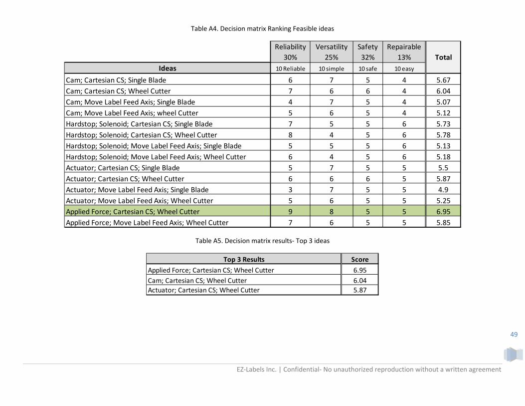
EZ‐Labels Inc. | Confidential‐ No unauthorized reproduction without a written agreement
49
Table A4. Decision matrix Ranking Feasible ideas
Table A5. Decision matrix results‐ Top 3 ideas
Reliability
30%
Versatility
25%
Safety
32%
Repairable
13%
Ideas 10 Reliable 10 simple 10 safe 10 easy
Cam; Cartesian CS; Single Blade 6 7 5 4 5.67
Cam; Cartesian CS; Wheel Cutter 7 6 6 4 6.04
Cam; Move Label Feed Axis; Single Blade 4 7 5 4 5.07
Cam; Move Label Feed Axis; wheel Cutter 5 6 5 4 5.12
Hardstop; Solenoid; Cartesian CS; Single Blade 7 5 5 6 5.73
Hardstop; Solenoid; Cartesian CS; Wheel Cutter 8 4 5 6 5.78
Hardstop; Solenoid; Move Label Feed Axis; Single Blade 5 5 5 6 5.13
Hardstop; Solenoid; Move Label Feed Axis; Wheel Cutter 6 4 5 6 5.18
Actuator; Cartesian CS; Single Blade 5 7 5 5 5.5
Actuator; Cartesian CS; Wheel Cutter 6 6 6 5 5.87
Actuator; Move Label Feed Axis; Single Blade 3 7 5 5 4.9
Actuator; Move Label Feed Axis; Wheel Cutter 5 6 5 5 5.25
Applied Force; Cartesian CS; Wheel Cutter 9 8 5 5 6.95
Applied Force; Move Label Feed Axis; Wheel Cutter 7 6 5 5 5.85
Total
Top 3 Results Score
Applied Force; Cartesian CS; Wheel Cutter 6.95
Cam; Cartesian CS; Wheel Cutter 6.04
Actuator; Cartesian CS; Wheel Cutter 5.87
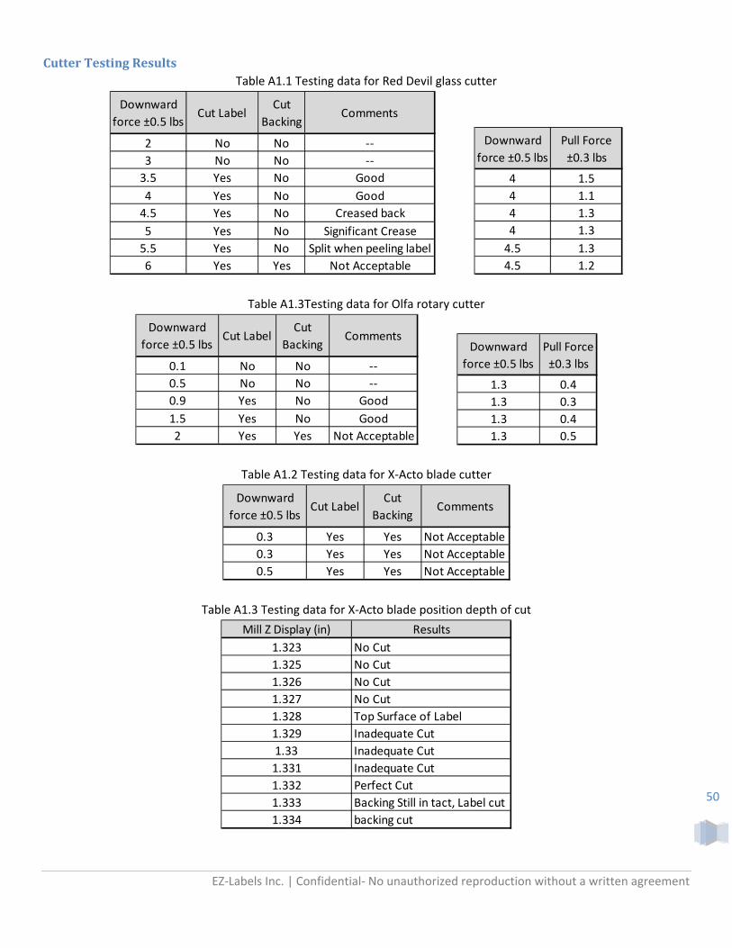
EZ‐Labels Inc. | Confidential‐ No unauthorized reproduction without a written agreement
50
CutterTestingResultsTable A1.1 Testing data for Red Devil glass cutter
Table A1.3Testing data for Olfa rotary cutter
Table A1.2 Testing data for X‐Acto blade cutter
Table A1.3 Testing data for X‐Acto blade position depth of cut
Downward
force ±0.5 lbsCut Label
Cut
BackingComments
2 No No ‐‐
3 No No ‐‐
3.5 Yes No Good
4 Yes No Good
4.5 Yes No Creased back
5 Yes No Significant Crease
5.5 Yes No Split when peeling label
6 Yes Yes Not Acceptable
Downward
force ±0.5 lbs
Pull Force
±0.3 lbs
4 1.5
4 1.1
4 1.3
4 1.3
4.5 1.3
4.5 1.2
Downward
force ±0.5 lbsCut Label
Cut
BackingComments
0.1 No No ‐‐
0.5 No No ‐‐
0.9 Yes No Good
1.5 Yes No Good
2 Yes Yes Not Acceptable
Downward
force ±0.5 lbs
Pull Force
±0.3 lbs
1.3 0.4
1.3 0.3
1.3 0.4
1.3 0.5
Downward
force ±0.5 lbsCut Label
Cut
BackingComments
0.3 Yes Yes Not Acceptable
0.3 Yes Yes Not Acceptable
0.5 Yes Yes Not Acceptable
Mill Z Display (in) Results
1.323 No Cut
1.325 No Cut
1.326 No Cut
1.327 No Cut
1.328 Top Surface of Label
1.329 Inadequate Cut
1.33 Inadequate Cut
1.331 Inadequate Cut
1.332 Perfect Cut
1.333 Backing Still in tact, Label cut
1.334 backing cut

EZ‐Labels Inc. | Confidential‐ No unauthorized reproduction without a written agreement
51
AppendixB:DrawingPacket‐SeeAttachedDocuments
ManufacturedPartsAssemblyMap:SeeAttachedDocuments

EZ‐Labels Inc. | Confidential‐ No unauthorized reproduction without a written agreement
52
AppendixC:VendorsandPricing
PurchasedPartsCostEstimate:
Part No Description Vendor QTY Cost Total Cost Purchased
55835K31 Cable Carrier McMaster 6 9.95 59.70 Yes
55835K1 Cable Carrier Mounting Bracket McMaster 2 5.85 11.70 Yes
TBN90XL031 45 tooth belt Misumi 1 3.28 3.28 Yes
TBN300XL031 150 tooth belt Misumi 1 5.68 5.68 Yes
TBN460XL031 230 tooth belt Misumi 1 6.48 6.48 Yes
ATP16XL031‐A‐NUE 16 tooth pulley keyed Misumi 1 13.20 13.20 Yes
ATP16XL031‐A‐PUC 16 tooth pulley 1/4" bore Misumi 2 10.56 21.12 Yes
ATP16XL031‐A‐P6 16 tooth pulley 6mm bore Misumi 3 10.22 30.65 Yes
1590A13 Draw latches. 10 Count McMaster 1 10.57 10.57 Yes
60355K45 3/8 ID bearing shielded McMaster 4 5.81 23.24 Yes
60355K43 1/4 ID bearing shielded McMaster 8 5.81 46.48 Yes
CPC‐AR15N‐0940‐20‐20 15mmx940mm Rail Anaheim Automation 1 92.00 92.00 Yes
CPC‐AR15N‐0700‐20‐20 15mmx700mm Rail Anaheim Automation 2 71.00 142.00 Yes
CPC‐AR15MNSZV0N Rail Block Anaheim Automation 4 38.00 152.00 Yes
SPPB‐M08 Cutter linear bearing 8mm diameter Applied.com 1 92.29 92.29 Yes
1447 131:1 Gearmotor with Encodor Pololu 3 39.95 119.85 Yes
1084 37D Gearmotor Bracket Pololu 2 7.95 15.90 Yes
97431A300 .25" E‐Clip McMaster 1 5.55 5.55 Yes
97431A320 .375" E‐Clip McMaster 1 7.82 7.82 YesN82E16835242011 Prolimatech PRO‐BV14 140mm Blue Vortex 14 Case Cooler Newegg 2 10.00 20.00 YesN82E16817148044 APEVIA ITX‐AP250W 250W Mini ITX Power Supply ‐ OEM Newegg 1 40.00 40.00 Yes
FF141B SilverStone 140mm Fan Filter Amazon 2 9.00 18.00 Yes
S‐22‐200‐23H SOLENOID Magnetic Sensor Systems 1 150.00 150.00 Yes
P50.25‐7T052 SENSOR MOUSER.COM 1 12.30 12.30 Yes
1530A51 HINGE MCMASTER McMaster 3 3.54 10.62 Yes
BRK‐18H‐240‐024‐375 ELECTROMAGNETIC BRAKE Anaheim Automation 1 107.00 107.00 Yes
2193 Arduino Due Microcontroller Polulo, etc 1 49.95 49.95 Yes
706 VNH2SP30 Motor Driver Polulo, etc 3 34.95 104.85 Yes
1403 Snap Action switch with 50mm lever Polulo, etc 2 0.95 1.90 Yes
98535A125 3/8 SHAFT ANSI KEY X 12" Mcmaster 1 1.67 1.67 Yes
58605K33 0.25 DIAMETER MAGNET Mcmaster 1 2.95 2.95 Yes
9657K312 Spring 1.00" L, .500" OD, .041" Wire, packs of 12 Mcmaster 1 9.8 9.80 Yes
BLU2300 BLUE SEA SYSTEMS 2300 Terminal Strip /BUSBAR‐10‐GANG‐COMMO 5 16.95 84.75 Yes
‐‐‐‐ Fastener Estimate ‐‐‐‐ ‐‐ ‐‐ 150.00 ‐‐‐
‐‐‐‐ Shipping Estimate ‐‐‐‐ ‐‐ ‐‐ 120.00 ‐‐‐
‐‐‐‐ Tax ‐‐‐‐ ‐‐ ‐‐ 117.86 ‐‐‐
Total 1743.30

EZ‐Labels Inc. | Confidential‐ No unauthorized reproduction without a written agreement
53
MaterialCostEstimate:
Part # Description Vendor QTY Cost Total Cost Purchased
100001 24" X 24" X 0.25" AL PLATE 6061‐T6 onlinemetals 2 88.58 177.16 Yes
100002‐1,‐2; 140002‐1,‐2 24" LENGTH 0.125" X 3.00" AL FLAT BAR 6061‐T6 onlinemetals 1 4.23 4.23 Yes
100003 24" LENGTH 1.50"X 0.125" SQUARE TUBING onlinemetals 2 10.93 21.86 Yes
100004 24" LENGTH 0.25" X 1.25" AL FLAT BAR 6061‐T6 onlinemetals 1 3.52 3.52 Yes
100005;110002 24" LENGTH 0.125" X 1.00" AL FLAT BAR 6061‐T6 onlinemetals 2 1.41 2.82 Yes
100006 12"x24"x.125" 6061 Al onlinemetals 1 28.05 28.05 Yes100007 12"x.25"x.75" 6061 Al onlinemetals 1 1.10 1.10 Yes
100008 .125"x.75"x12" 6061 Al onlinemetals 1 0.55 0.55 Yes
100009 12" LENGTH 0.375" X .5" AL BAR 6061‐T6 onlinemetals 1 1.10 1.10 Yes
100010 24" LENGTH 0.125" X 1.25" AL FLAT BAR 6061‐T6 onlinemetals 1 1.76 1.76 Yes
100011 12" LENGTH 0.75" X .75" AL BAR 6061‐T6 onlinemetals 1 3.30 3.30 Yes
110001 24" LENGTH 0.5" X 3.00" AL FLAT BAR 6061‐T6 onlinemetals 1 16.93 16.93 Yes
111001 12" X 12" X 0.25" AL PLATE 6061‐T6 onlinemetals 3 28.54 85.62 Yes
111101 24" length 0.375 cold finish AL round 6061‐T651 onlinemetals 3 2.85 8.55 Yes
112001; 113001 24" length 0.50" cold finish AL round 6061‐T651 onlinemetals 3 5.06 15.18 Yes
112002 Roller 87235K82 36" length Polyurethane 60A tube ID:0.5" OD:1.25" McMaster 1 77.01 77.01 Yes
112003 12" length 1.25" X 1.25" AL 6061‐T6 extruded square bar onlinemetals 1 9.18 9.18 Yes
112004 12" length 1.00" X 1.25" AL 6061‐T6 extruded square bar onlinemetals 1 7.35 7.35 Yes130002 24"x1"x1.25" Extruded Aluminum Bar Square 6061 T6511 onlinemetals 1 14.11 14.11 Yes
150001;150003 24"x.125"x2.5 Extruded Aluminum Bar Square 6061 T6511 onlinemetals 1 3.52 3.52 Yes
150002 .125"x1.5"x 12" Extruded Aluminum Bare Rectangle 6061 T6511 onlinemetals 1 1.10 1.10 Yes
150004 .5"x.5"x12" Extruded Aluminum Bare Square 6061 onlinemetals 1 1.47 1.47 Yes
151001 .75"x.75"x12" Extruded Aluminum Bare Square steel onlinemetals 1 5.49 5.49 Yes
151002 0.375"X12" cold finish rod onlinemetals 1 1.05 1.05 Yes
151003 Scoremaster 03‐703 cutter head Stained Glass Workshop 3 18.69 56.07 Yes160001 1.25"x1.5"x12" EXTRUDED Aluminum Bare Rectangle 6061 Onlinemetals 1 11.02 11.02 Yes
160002 .25" Drive Shaft 1327K66 McMaster 1 6.94 6.94 Yes
180001;2,3,4 0.118 X 24 X 24 ACRYLIC onlinemetals 2 11.40 22.80 Yes
180005 0.118 X 24 X 48 ACRYLIC onlinemetals 1 22.80 22.80 Yes
‐‐‐‐ Shipping Estimate ‐‐‐ ‐‐ ‐‐‐ 120 ‐‐‐
‐‐‐‐ Tax ‐‐‐ ‐‐ ‐‐‐ 48.93 ‐‐‐
Total Cost ‐‐ ‐‐‐ 731.64

EZ‐Labels Inc. | Confidential‐ No unauthorized reproduction without a written agreement
54
FinalOrderHistory:
Date Vendor Items Purchased QTY Total Purchased By
1/15/2013 Feedroller.com HP Transfer roller RF5‐0596 1 17.40 Lorne Stoops
1/18/2013 Home Depot Glass Cutter 1 4.09 Lorne Stoops
1/20/2013 Feedroller.com HP 2100 Pressure roller RF5‐2601 4 63.58 Lorne Stoops
1/30/2013 McMaster Steel Precision Compression Spring 1 154.88 Nathan Cheadle3/8" Steel Flange-Mount Linear Ball Bearing 13/8" Steel Thrust Ball Bearing 13/8"-16 Stainless Steel Spade Head Thumb Screw 1Combination Push/Pull Sealed Linear Solenoid 1Neoprene Spring Rubber, Tube 1
1/30/2013 Onlinemetals 0.75"X.75"X12" AL SQUARE BAR 1 68.83 Nathan Cheadle0.75"X.24" STEEL ROUND 11.75"X12" AL ROUND 1.375"X12" STEEL ROUND 1.375"X8"X8" AL PLATE 1
2/5/2013 Magnetic Sensor SystemTubular Push Solenoid S‐22‐200‐23H 1 175.24 Tony Wang
3/16/2013 Onlinemetals 24" X 24" X 0.25" AL PLATE 6061‐T6 2 283.78 Lorne Stoops
24" LENGTH 0.125" X 3.00" AL FLAT BAR 6061‐T6 1
24" LENGTH 1.50"X 0.125" SQUARE TUBING 2
24" LENGTH 0.125" X 1.25" AL FLAT BAR 6061‐T6 1
24" length 0.375 cold finish AL round 6061‐T651 324" length 0.50" cold finish AL round 6061‐T651 3
12" length 1.25" X 1.25" AL 6061‐T6 extruded square bar 1
12" length 1.00" X 1.25" AL 6061‐T6 extruded square bar 1
.5"x.5"x12" Extruded Aluminum Bare Square 6061 1
.75"x.75"x12" Extruded Aluminum Bare Square steel 1
3/16/2013 eBay Scoremaster Replacement Head 1 18.00 Lorne Stoops
3/19/2013 McMaster Draw latches. 10 Count 1 118.57 Lorne Stoops
3/8 ID bearing shielded 4
1/4 ID bearing shielded 8
.25" E‐Clip 1
.375" E‐Clip 1
0.25 DIAMETER MAGNET 1.25" Drive Shaft 1327K66 1
3/19/2013 McMaster Roller 87235K82 36" length Polyurethane 60A tube ID:0.5" OD:1.2 1 88.61 Lorne Stoops
4/3/2013 Ace Hardware 10‐32 Tap 1 4.96 Lorne Stoops
4/6/2013 Onlinemetals 24" LENGTH 0.25" X 1.25" AL FLAT BAR 6061‐T6 2 241.06 Lorne Stoops
24" LENGTH 0.125" X 1.00" AL FLAT BAR 6061‐T6 1
12"x24"x.125" 6061 Al 1
12"x.25"x.75" 6061 Al 1
24" LENGTH 0.5" X 3.00" AL FLAT BAR 6061‐T6 1
12" X 12" X 0.25" AL PLATE 6061‐T6 3
24"x1"x1.25" Extruded Aluminum Bar Square 6061 T6511 1
.125"x1.5"x 12" Extruded Aluminum Bare Rectangle 6061 T6511 1
1.25"x1.5"x12" EXTRUDED Aluminum Bare Rectangle 6061 1
0.118 X 24 X 24 ACRYLIC 2
0.118 X 24 X 48 ACRYLIC 1
4/7/2013 Amazon 140mm fan filter 2 19.42 Lorne Stoops
4/7/2013 Newegg Prolimatech Pro‐BV14 140mm fan 2 69.46 Lorne Stoops
Apevia itx‐ap250w power supply 1

EZ‐Labels Inc. | Confidential‐ No unauthorized reproduction without a written agreement
55
4/7/2013 Stained Glass Workshop Scoremaster 03‐703 cutter head 3 61.22 Lorne Stoops
4/8/2013 Mcmaster 8mm shaft 200mm length 1 99.86 Lorne Stoops
Cable carrier 6 ft 1
cable carrier mounting bracket 2
Hinge 3
4/8/2013 Misumi 45 tooth XL timing belt 1 81.85 Lorne Stoops
150 tooth XL timing belt 1
230 tooth XL timing belt 1
Timing Pulley 6
4/8/2013 Anaheim Automation 700mm rail 2 545.27 Lorne Stoops
940mm rail 1
Rail block 4
Electromagnetic brake 1
4/9/2013 Onlinemetals 0.5"x12" aluminum round 3 23.36 Lorne Stoops
4/10/2013 Pololu Arduino Due Microcontroller 1 308.4 Lorne Stoops
VNH2SP30 Motor Driver 3
Snap Action switch with 50mm lever 2
131:1 Gearmotor with Encodor 3
37D Gearmotor Bracket 2
4/10/2013 Ralphs Gallon ziplock bags 1 5.71 Lorne Stoops
4/16/2013 Home Depot Epoxy 1 5.91 Lorne Stoops
4/24/2013 Ace Hardware Threadlocker 1 21.76 Lorne Stoops
Silicon Glue 1
Metal Epoxy Putty 1
Sandpaper 2
4/28/2013 McMaster Tube Made of Teflon(R) PTFE, 5/8" OD X 1/4" ID, 1' Length 1 48.81 Lorne Stoops
Aluminum (Alloy 6061), 1/8" Thick X 2‐1/2" Width X 3' Length 1
1/4" ID Bearing 1
Steel Compression Spring 1.00" L, .500" OD, .041" Wire, packs of 1 1
5/2/2013 Mouser.com Optical Sensor 1 21.27 Tony Wang
5/2/2013 Ace Hardware Fasteners 68.69 Tony Wang
5/5/2013 Ace Hardware Fasteners 50.46 Lorne Stoops
5/6/2013 Ace Hardware Fasteners 10.51 Lorne Stoops
5/7/2013 Radio Shack wire, switches, transistors 31.53 Lorne Stoops
5/7/2013 Mcmaster M4x55 screws 11.34 Lorne Stoops
5/9/2013 Amazon Bus Bar 5 94.85 Lorne Stoops
5/9/2013 Pololu VNH2SP30 Motor Driver 2 74.85 Lorne Stoops
5/13/2013 Home Depot Denatured Alcohol, Silicone lubricant 11.61 Lorne Stoops
5/15/2013 Ace Hardware Fasteners 17.97 Lorne Stoops
5/16/2013 Ace Hardware Fasteners 4.58 Lorne Stoops
5/17/2013 Ace Hardware Fasteners 11.40 Lorne Stoops
5/17/2013 Radio Shack Spade connectors 12.39 Lorne Stoops
5/20/2013 Ace Hardware Fasteners, Silicon Glue 6.04 Lorne Stoops
5/20/2013 McMaster Hinges 3 10.47 Lorne Stoops
5/26/2013 Radio Shack Power Resistors 4 18.90 Lorne Stoops
Barrel connector 1
Cable Wrap 1
5/28/2013 El Corral Bookstore Poster Board 2 21.93 Lorne Stoops
3 Ring Binder 2
6/1/2013 Newegg Power Supply 1 52.97 Lorne Stoops
3061.79 Total
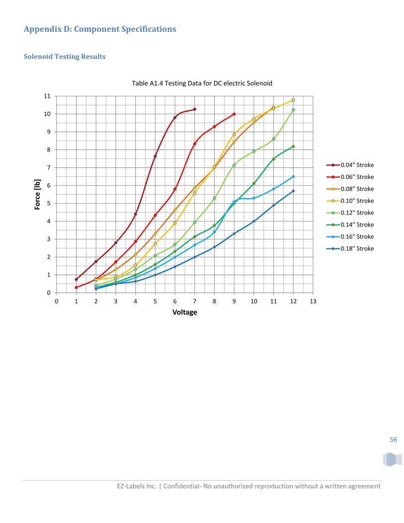
EZ‐Labels Inc. | Confidential‐ No unauthorized reproduction without a written agreement
56
AppendixD:ComponentSpecifications
SolenoidTestingResults
Table A1.4 Testing Data for DC electric Solenoid
0
1
2
3
4
5
6
7
8
9
10
11
0 1 2 3 4 5 6 7 8 9 10 11 12 13
Force [lb]
Voltage
0.04" Stroke
0.06" Stroke
0.08" Stroke
0.10" Stroke
0.12" Stroke
0.14" Stroke
0.16" Stroke
0.18" Stroke

CALPOLYMECHANICALENGINEERINGDEPARTMENT
TemperatureEffectonSolenoidForceOutput
NathanCheadle,TonyWang5/29/2013

1
Introduction During fall 2012 a team of undergraduate engineers took on a senior project involving the design of a
trial prescription label cutting machine. Through a meticulous process of brainstorming, design, and redesign a
final product was created which uses a solenoid to cut the label stock. Due to the nature of the design, solenoid
temperature is a major concern for the following reasons:
The solenoid is mounted to a heat sink smaller than that specified in the datasheet
It will be functioning within a small closed off acrylic case
The wire coil will increase in resistance as temperature increases
Due to the lack of heat dissipation, increases in temperature can cause the solenoid performance to
become unpredictable. Therefore the goal of this project is to model and test the effects heating will have on
the force output of the solenoid, allowing for better prediction of performance under normal use.
Background A solenoid is a device that uses a coil of wiring with current running through it to generate a magnetic
field. The magnetic field forces a moveable plunger in a certain direction depending on the orientation of the
magnetic field. For the On‐Demand Label Cutter Senior Project, a solenoid is used to provide the downward
force required to cut through the label material. Due to the use of electrical wiring in the solenoid, temperature
is a major concern in regards to the proper function of the solenoid. This is because as current runs through the
wire, the resistance in the wire causes it to heat up. As the wire heats up, it loses conductivity which weakens
the magnetic field. A weaker magnetic field would mean the force output is smaller. This results in a drop in
force when the solenoid runs for a long period of time.
The goal of this experiment is to determine if the force output from the solenoid ever falls below the
minimum force needed due to self heating. Through prior testing it was determined the cut head required a
minimum force of 4lbs and a maximum of 5lbs to properly cut through the label stock. If the force output were
to fall below 4lb, the cut head would fail to cut through the label stock rendering the machine useless. By
performing the test we can not only determine if further heat dissipation is required in terms of additional heat
sink and forced ventilation but also, in a worst case scenario, recommend a duty cycle for the solenoid.
As mentioned above, by increasing temperature of the coil there is a measureable increase in coil
resistance. More specifically, for every degree above 20°C, an increase in temperature of one degree would
increase the resistance by .393 percent. Rearranging the equation we can get a function for the ratio of
resistance change in terms of temperature.
1 0.00393
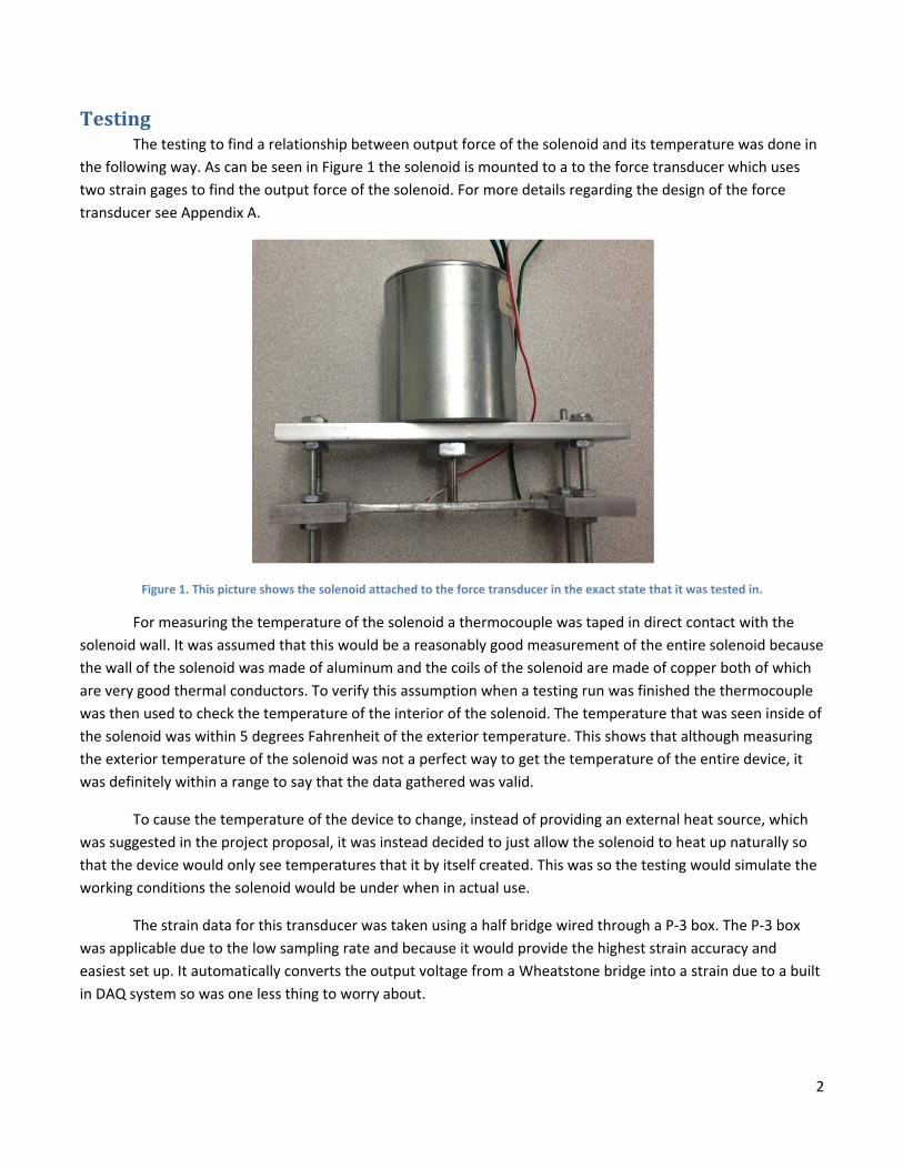
2
Testing The testing to find a relationship between output force of the solenoid and its temperature was done in
the following way. As can be seen in Figure 1 the solenoid is mounted to a to the force transducer which uses
two strain gages to find the output force of the solenoid. For more details regarding the design of the force
transducer see Appendix A.
Figure 1. This picture shows the solenoid attached to the force transducer in the exact state that it was tested in.
For measuring the temperature of the solenoid a thermocouple was taped in direct contact with the
solenoid wall. It was assumed that this would be a reasonably good measurement of the entire solenoid because
the wall of the solenoid was made of aluminum and the coils of the solenoid are made of copper both of which
are very good thermal conductors. To verify this assumption when a testing run was finished the thermocouple
was then used to check the temperature of the interior of the solenoid. The temperature that was seen inside of
the solenoid was within 5 degrees Fahrenheit of the exterior temperature. This shows that although measuring
the exterior temperature of the solenoid was not a perfect way to get the temperature of the entire device, it
was definitely within a range to say that the data gathered was valid.
To cause the temperature of the device to change, instead of providing an external heat source, which
was suggested in the project proposal, it was instead decided to just allow the solenoid to heat up naturally so
that the device would only see temperatures that it by itself created. This was so the testing would simulate the
working conditions the solenoid would be under when in actual use.
The strain data for this transducer was taken using a half bridge wired through a P‐3 box. The P‐3 box
was applicable due to the low sampling rate and because it would provide the highest strain accuracy and
easiest set up. It automatically converts the output voltage from a Wheatstone bridge into a strain due to a built
in DAQ system so was one less thing to worry about.

3
Results
Calibration The transducer was calibrated using weights ranging from 1lb to 8lb. The actual values that ended up
being measured through the transducer were off from those predicted from the FEA model. This was
determined to be due to the fact that the end supports of the transducer were somewhere between being a
fixed‐fixed and a pinned‐pinned. Both models were analyzed in FEA and the strain profile could best be
summarized as an average of the fixed‐fixed and pinned‐pinned model. The reason was due to the design of the
transducer. It was due to combination of the nuts keeping the ends qausi‐fixed while the low stiffness rods
allowing for bending attributed to the result.
Figure 2. Calibration curve for force transducer
TemperatureChangewithRespecttoTimeThe data in Figure 3 shows that temperature does increase with respect to time, but as time goes on the
temperature increases at a slower and slower rate. This is expected because as will be shown in the next section
as the exterior temperature of the solenoid increases so does the rate of heat transfer from natural convection.
y = 147.51x ‐ 14.429R² = 0.9976
0
200
400
600
800
1000
1200
1400
0 2 4 6 8 10
microStrain
Pounds

4
Figure 3. This is a graph that shows the three different runs of data for the testing of the solenoid, and it graphs the temperature of the solenoid in Fahrenheit with respect to time in seconds.
ChangeinForcewithRespecttoTemperatureChangeThe following data shows all three runs temperature with respect to force. From Figure 4 a few things
can be seen first of all. The data from the first run has some obvious outliers in comparison to runs two and
three and that the data because it is so inconsistent should not be considered valid. The second and third runs
both show similar relations in regards to force and temperature. This is that at least as far as this data shows as
temperature increases the force output of the solenoid tends to increase slightly.
The reason that is believed to have caused issues with the first run is that during the testing if the wires
touch and this goes unnoticed, the perceived strain that is shown by the data acquisition system will appear to
be much different than is actually there.
Figure 4. This graph displays the force as it relates to temperature for all three runs.
y = ‐1E‐06x2 + 0.0138x + 75.559
0
20
40
60
80
100
120
0 1000 2000 3000 4000 5000
Temperature (F)
Time (s)
Run One
Run Two
Run Three
3.00
4.00
5.00
6.00
7.00
8.00
9.00
65 75 85 95 105 115
Force (lb)
Temperature (F)
Run Two
Run Three

5
AnalysisofResults
HeatTransferfromSolenoidFor this testing a good analysis that was thought to go along with the testing would be how much heat
the solenoid would be able to dissipate based on the temperature of its exterior. For this calculation it was
assumed that all heat transfer occurred through natural convection, and that the convection coefficient for the
top of the solenoid could be modeled as the upper surface of a hot plate and the convection coefficient for the
sides could be modeled as a vertical flat plate. The ambient temperature of the air was also assumed to be 298K.
A graph of the resulting heat transfer based on temperature can be found in Figure 5. A sample calculation for
this data can be found in Appendix C.
Figure 5. This figure shows the relationship between the heat transferred to the atmosphere and the temperature of the outer surface of the solenoid.
Based on these results it is not expected for the solenoid to keep significantly increasing in temperature,
especially not to a dangerous level for the solenoid which is about 170 degrees Fahrenheit or 350 Kelvin. This is
confirmed by the test data that is based on a polynomial curve fit the temperature is expected to level off after a
time of roughly 2 hours at a temperature of 123 degrees Fahrenheit.
SolenoidTemperatureRelativetoTimeBy knowing the Resistance Factor along with the Thermal Resistance and the power at which the
solenoid operates at, we can calculate the temperature change with the following equation:
0
10
20
30
40
50
60
70
80
275 295 315 335 355 375 395 415
Heat Transfer (W
)
Temperature (K)

6
(http://www.solenoids.com/imgp/tech4_4.jpg)
Due to the fact that it would be redundant to have this equation if the temperature change (TR) was
known, an equation based off the temperature vs time plot is inserted. The initial temperature was also
increased from 20°C to 25°C to reflect the actual testing environment.
25 ∗ ∗ 11 0.00393 ∗ 8 ∗ 10 0.007 0.81
Further simplification leads to canceling similar terms in P and K which results in a function in terms of
initial temperature and time only.
251 0.00393 ∗ 8 ∗ 10 0.007 0.81
8 ∗ 10 0.007 0.81 1
This equation is a simplified way of viewing solenoid self‐heating in terms of time. It is important to keep
in mind though that due to the K being held constant this is an underestimate of the actual temperature. The
limitation of this function is that it applies only to the specific solenoid tested at the power tested. But the
function can be used to predict the minimum temperature the solenoid will be at a time interval after being
turned on. Plotting out the function tells us the maximum temperature will occur after 4000 seconds. Due to
the profile being based on a second order polynomial, the max temp will be reached before the actual max.
Therefore the model gives us a “worst case scenario” of what the solenoid behavior could be.
The thermal resistivity was also plotted on the same time scale as the temperature. Due to it being
based on the same temperature profile it has the same shaped curve as temperature.

7
Figure 6. Solenoid temperature relative to time modeled by a polynomial and Thermal Resistivity
Conclusion Through testing we were able to determine that the solenoid would able to be run for extended periods
of time within work conditions without overheating. The original concerns of having a small heat‐sink, being in
an enclosure, and sensitivity to temperature were unfounded. Instead, it was determined that due to being run
at lower than designed power for continuous cycle limited the self heating effects and natural convection was
able to keep the solenoid cool enough to maintain a safe operating temperature for extended periods of time.
So in conclusion, the solenoid would be able to be run for long periods of time under its designed conditions of
at 7volts and 0.66amps in an enclosed area and still maintain the required force output.
Further analysis can be done to the model to find a better fit for extended self heating profile of the
solenoid. Finding the heat distribution inside the solenoid would also be nice to have but that would require
breaking open the only on‐hand solenoid. Further FEA can also be done on the transducer to find better end
conditions to properly model the expected strain at the strain gauges. Though not entirely relevant, the solenoid
can also be tested at higher power rating to see at what power it does start overheating and decrease in force
output.

8
AppendixA
TransducerCalibration
OverviewThis transducer was designed using a mix of beam theory and a converged shell element FEA model. Two
models of each type were made with one set having a pinned boundary condition and the other having a fixed
boundary condition. When both of these models were compared with actual strain data neither appeared
completely correct, but the data from the pinned‐pinned boundary conditions most closely matched the
calculated results. All of the data was tabulated using a beam cross section that was 3 inches long, .1 inches thick
and .275 inches wide. This particular sizing gave us roughly 500 microstrain in the force region that we were
attempting to measure, while also giving us enough of a safety factor to handle the largest force that the
solenoid could output. A table overviewing the results from the calibration can be found in Table A.1 and Figure
A.1.
FEA Beam Theory
Tested Results
Force (lbf)
Moment (in-lbf) (Fixed Fixed)
Moment (in-lbf) (Pinned Pinned)
Micro Strain ( Fixed Fixed)
Micro Strain (Pinned Pinned)
Micro Strain ( Fixed Fixed)
Micro Strain (Pinned Pinned)
Micro Strain
1 0.28175 0.84475 63 198 54 163 145
2 0.5635 1.6895 126 396 109 327 290
3 0.84525 2.53425 189 594 163 490 435
4 1.127 3.379 251 792 218 653 580
5 1.40875 4.22375 314 990 272 816 725
6 1.6905 5.0685 377 1187 327 980 869
7 1.97225 5.91325 440 1385 381 1143 1014
8 2.254 6.758 503 1583 436 1306 1159
9 2.53575 7.60275 565 1781 490 1470 1304
10 2.8175 8.4475 628 1979 545 1633 1449
Table A.1: This table shows an overview of the expected strains and actual strains seen in the force transducer that was designed to measure the output force of the solenoid.
Figure A.1: This figure shows the graphed relationships between force and strain for all of the different models relative to the tested results.
0
500
1000
1500
2000
2500
0 2 4 6 8 10 12
Micro Strain
Force
FEA Fixed Fixed
FEA Pinned Pinned
Beam Theory Fixed Fixed
Beam Theory Pinned Pinned
Tested Results

9
FEAModelThe FEA model which is pictured in Figure A.2used shell elements that converged at roughly 1/32” in size. All of
the elements were perfectly square so all the elements were of a high quality. The solenoid load was modeled as
a contact between the plunger and the beam portion of the transducer. This made sure that no point loads were
present near the location where strain numbers were wanted to be taken.
Figure A.2 This is an image of the results of the Abaqus model used to help design the final force transducer.
PlungerLengthThe plunger length was set using threaded rods with nuts on each end. This allowed the distance between the
un‐deflected beam and the solenoid plunger to be set within a couple thousandths of an inch. This distance was
determined using calipers to measure the distance at the four separate threaded rods to also make sure that the
beam and the mount were parallel as well. A picture of the assembly that set the stroke length of the solenoid
can be seen in Figure A.4.
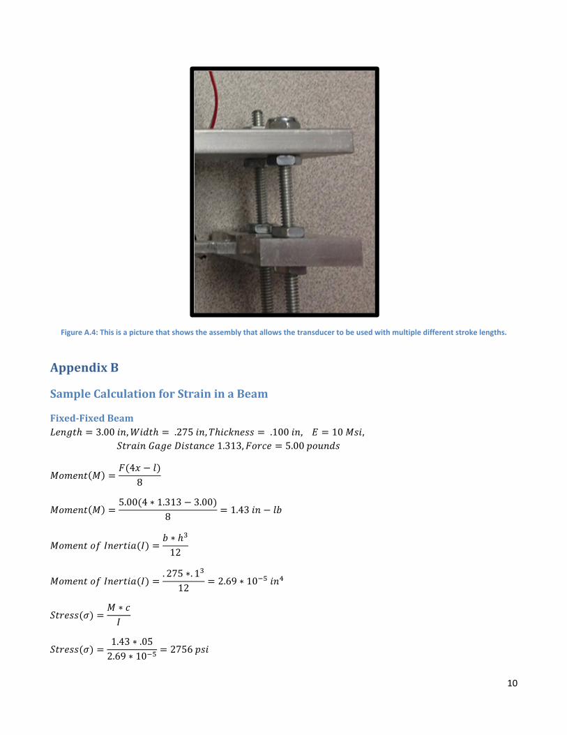
10
Figure A.4: This is a picture that shows the assembly that allows the transducer to be used with multiple different stroke lengths.
AppendixB
SampleCalculationforStraininaBeam
Fixed‐FixedBeam3.00 , .275 , .100 , 10 ,
1.313, 5.00
48
5.00 4 ∗ 1.313 3.008
1.43
∗12
. 275 ∗. 1
122.69 ∗ 10
∗
1.43 ∗ .052.69 ∗ 10
2756

11
275610 ∗ 10
272
Pinned‐PinnedBeam3.00 , .275 , .100 , 10 ,
1.313, 5.00
∗2 2
5.00 ∗ 1.3132
5.00 1.3133.002
4.22
∗12
. 275 ∗. 1
122.69 ∗ 10
∗
4.22 ∗ .052.69 ∗ 10
8133
813310 ∗ 10
816
AppendixC
SampleCalculationsforNaturalConvection
1
/2 .00336
∗
9.81 ∗ .00336 306 298 . 01271.7 ∗ 10 ∗ 2.4 ∗ 10
1.22 ∗ 10

12
Pr
Pr 2.4 ∗ 101.7 ∗ 10
.708
.54 ∗
.54 1.22 ∗ 10 3.19
.8250.387 ∗
1 .
.8250.387 ∗ 1.22 ∗ 10
1 .
.
2.18
∗
. ∗ . ∗.
.
∗
. ∗ . ∗.
.
∗ ∗
8.50 ∗ ∗. 05084
∗ 306 298 2.54
2.18 ∗ ∗ .0508 ∗ .0556 ∗ 306 298 .338
2.54 .338 2.88
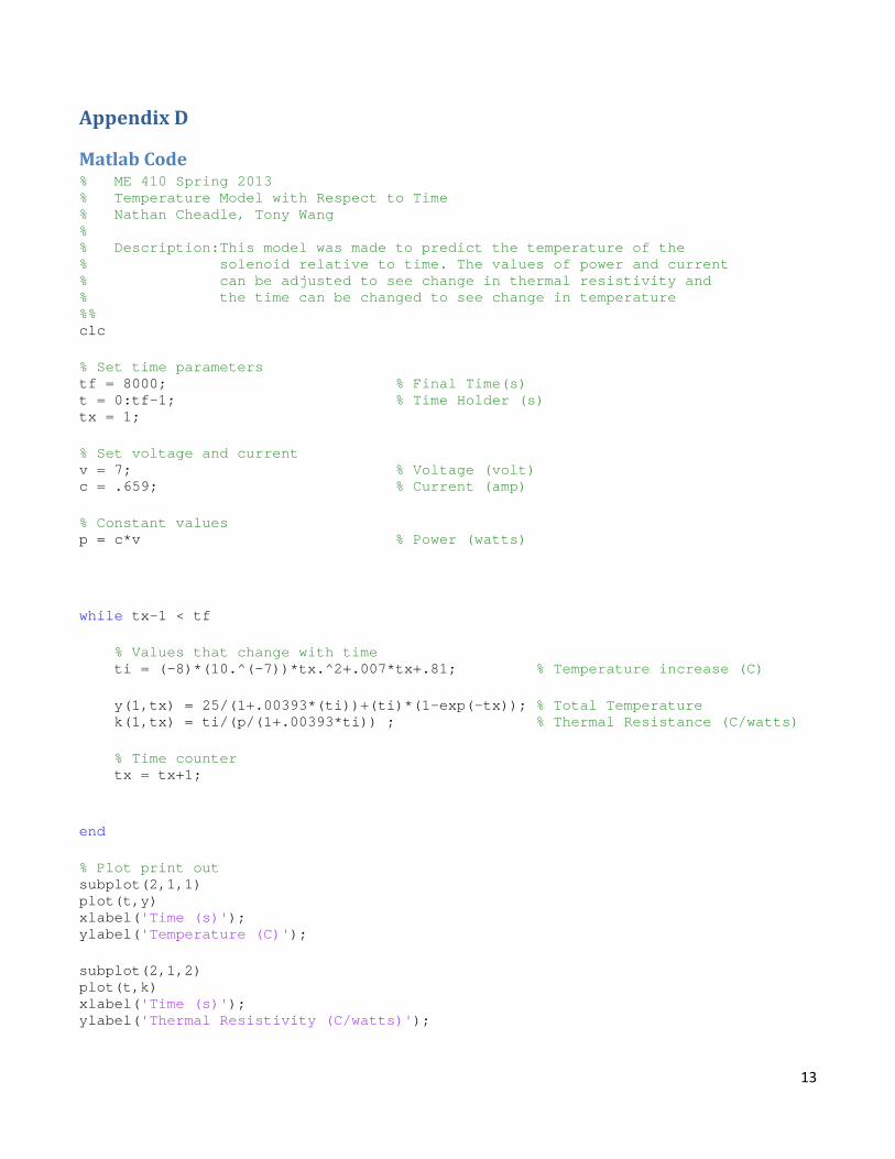
13
AppendixD
MatlabCode% ME 410 Spring 2013 % Temperature Model with Respect to Time % Nathan Cheadle, Tony Wang % % Description:This model was made to predict the temperature of the % solenoid relative to time. The values of power and current % can be adjusted to see change in thermal resistivity and % the time can be changed to see change in temperature %% clc % Set time parameters tf = 8000; % Final Time(s) t = 0:tf-1; % Time Holder (s) tx = 1; % Set voltage and current v = 7; % Voltage (volt) c = .659; % Current (amp) % Constant values p = c*v % Power (watts) while tx-1 < tf % Values that change with time ti = (-8)*(10.^(-7))*tx.^2+.007*tx+.81; % Temperature increase (C) y(1,tx) = 25/(1+.00393*(ti))+(ti)*(1-exp(-tx)); % Total Temperature k(1,tx) = ti/(p/(1+.00393*ti)) ; % Thermal Resistance (C/watts) % Time counter tx = tx+1; end % Plot print out subplot(2,1,1) plot(t,y) xlabel('Time (s)'); ylabel('Temperature (C)'); subplot(2,1,2) plot(t,k) xlabel('Time (s)'); ylabel('Thermal Resistivity (C/watts)');

EZ‐Labels Inc. | Confidential‐ No unauthorized reproduction without a written agreement
57
AppendixE:AnalysisConcerningFinalDesign
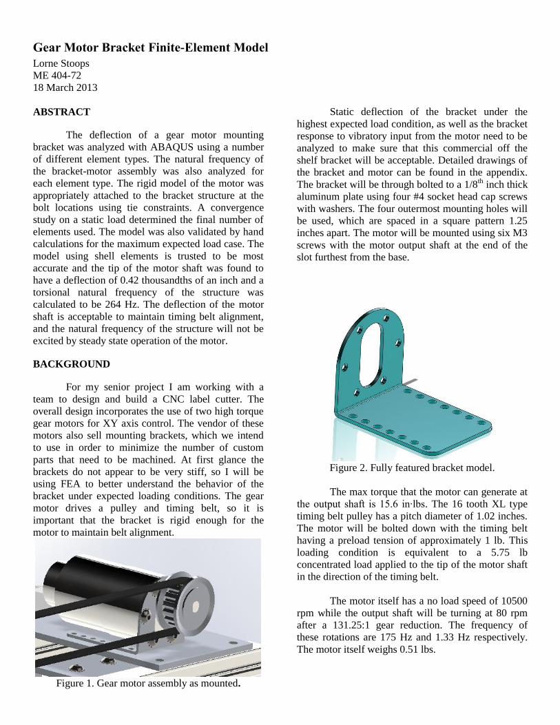
Gear Motor Bracket Finite-Element Model
Lorne Stoops
ME 404-72
18 March 2013
ABSTRACT
The deflection of a gear motor mounting
bracket was analyzed with ABAQUS using a number
of different element types. The natural frequency of
the bracket-motor assembly was also analyzed for
each element type. The rigid model of the motor was
appropriately attached to the bracket structure at the
bolt locations using tie constraints. A convergence
study on a static load determined the final number of
elements used. The model was also validated by hand
calculations for the maximum expected load case. The
model using shell elements is trusted to be most
accurate and the tip of the motor shaft was found to
have a deflection of 0.42 thousandths of an inch and a
torsional natural frequency of the structure was
calculated to be 264 Hz. The deflection of the motor
shaft is acceptable to maintain timing belt alignment,
and the natural frequency of the structure will not be
excited by steady state operation of the motor.
BACKGROUND
For my senior project I am working with a
team to design and build a CNC label cutter. The
overall design incorporates the use of two high torque
gear motors for XY axis control. The vendor of these
motors also sell mounting brackets, which we intend
to use in order to minimize the number of custom
parts that need to be machined. At first glance the
brackets do not appear to be very stiff, so I will be
using FEA to better understand the behavior of the
bracket under expected loading conditions. The gear
motor drives a pulley and timing belt, so it is
important that the bracket is rigid enough for the
motor to maintain belt alignment.
Figure 1. Gear motor assembly as mounted.
Static deflection of the bracket under the
highest expected load condition, as well as the bracket
response to vibratory input from the motor need to be
analyzed to make sure that this commercial off the
shelf bracket will be acceptable. Detailed drawings of
the bracket and motor can be found in the appendix.
The bracket will be through bolted to a 1/8th inch thick
aluminum plate using four #4 socket head cap screws
with washers. The four outermost mounting holes will
be used, which are spaced in a square pattern 1.25
inches apart. The motor will be mounted using six M3
screws with the motor output shaft at the end of the
slot furthest from the base.
Figure 2. Fully featured bracket model.
The max torque that the motor can generate at
the output shaft is 15.6 in∙lbs. The 16 tooth XL type
timing belt pulley has a pitch diameter of 1.02 inches.
The motor will be bolted down with the timing belt
having a preload tension of approximately 1 lb. This
loading condition is equivalent to a 5.75 lb
concentrated load applied to the tip of the motor shaft
in the direction of the timing belt.
The motor itself has a no load speed of 10500
rpm while the output shaft will be turning at 80 rpm
after a 131.25:1 gear reduction. The frequency of
these rotations are 175 Hz and 1.33 Hz respectively.
The motor itself weighs 0.51 lbs.
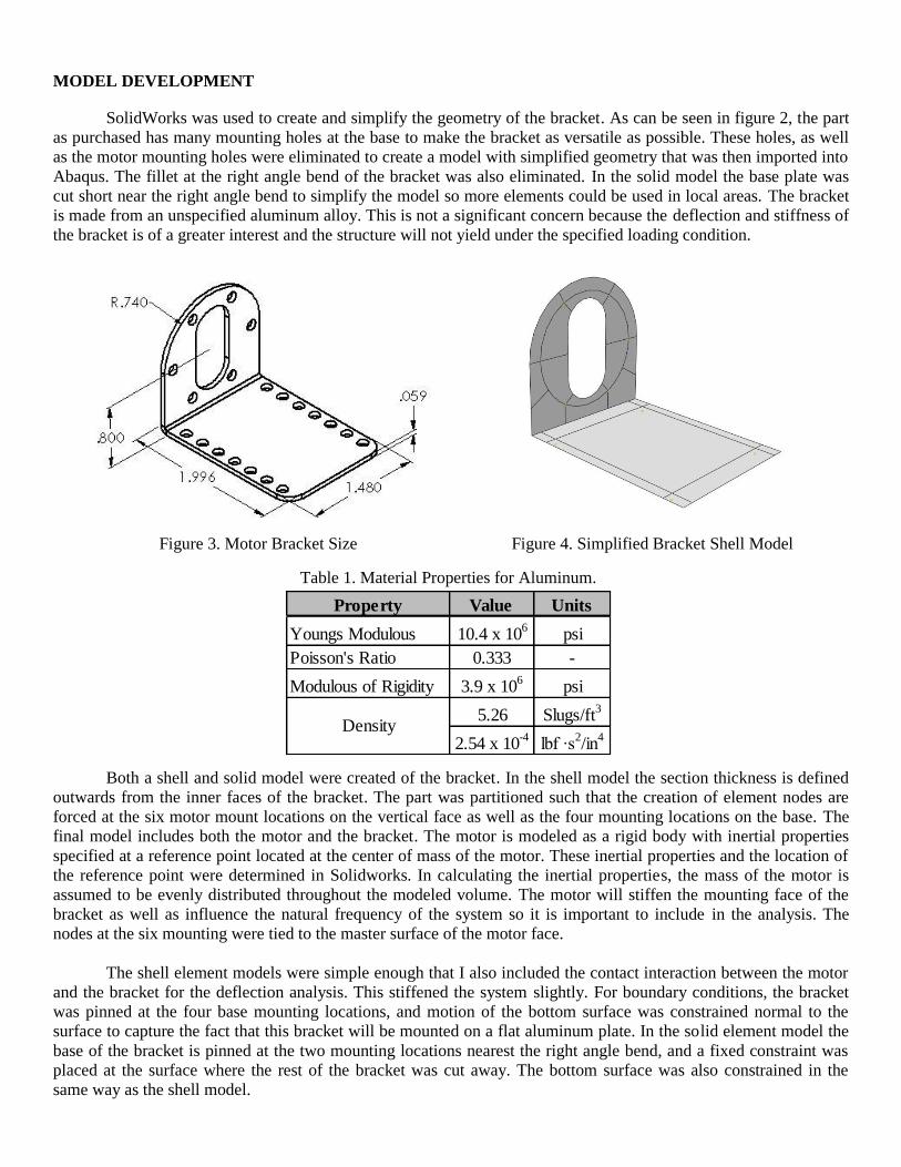
MODEL DEVELOPMENT
SolidWorks was used to create and simplify the geometry of the bracket. As can be seen in figure 2, the part
as purchased has many mounting holes at the base to make the bracket as versatile as possible. These holes, as well
as the motor mounting holes were eliminated to create a model with simplified geometry that was then imported into
Abaqus. The fillet at the right angle bend of the bracket was also eliminated. In the solid model the base plate was
cut short near the right angle bend to simplify the model so more elements could be used in local areas. The bracket
is made from an unspecified aluminum alloy. This is not a significant concern because the deflection and stiffness of
the bracket is of a greater interest and the structure will not yield under the specified loading condition.
Figure 3. Motor Bracket Size Figure 4. Simplified Bracket Shell Model
Both a shell and solid model were created of the bracket. In the shell model the section thickness is defined
outwards from the inner faces of the bracket. The part was partitioned such that the creation of element nodes are
forced at the six motor mount locations on the vertical face as well as the four mounting locations on the base. The
final model includes both the motor and the bracket. The motor is modeled as a rigid body with inertial properties
specified at a reference point located at the center of mass of the motor. These inertial properties and the location of
the reference point were determined in Solidworks. In calculating the inertial properties, the mass of the motor is
assumed to be evenly distributed throughout the modeled volume. The motor will stiffen the mounting face of the
bracket as well as influence the natural frequency of the system so it is important to include in the analysis. The
nodes at the six mounting were tied to the master surface of the motor face.
The shell element models were simple enough that I also included the contact interaction between the motor
and the bracket for the deflection analysis. This stiffened the system slightly. For boundary conditions, the bracket
was pinned at the four base mounting locations, and motion of the bottom surface was constrained normal to the
surface to capture the fact that this bracket will be mounted on a flat aluminum plate. In the solid element model the
base of the bracket is pinned at the two mounting locations nearest the right angle bend, and a fixed constraint was
placed at the surface where the rest of the bracket was cut away. The bottom surface was also constrained in the
same way as the shell model.
Property Value Units
Youngs Modulous 10.4 x 10⁶
psi
Poisson's Ratio 0.333 -
Modulous of Rigidity 3.9 x 10⁶
psi
5.26 Slugs/ft3
2.54 x 10⁻⁴
lbf ∙s2/in
4Density
Table 1. Material Properties for Aluminum.

MESH DEVELOPMENT & CONVERGENCE
The static deflection and vibration analysis were both carried out using the following element types:
Linear quadrilateral shell elements- reduced integration
Linear triangular shell elements- reduced integration
Quadratic hexahedral solid elements- reduced integration
The bracket was partitioned to simplify the meshing geometry and ease up the transitions between
the circular slot and bracket edge to the rectangular bend and edges. Convergence of the models was checked
by observing the deflection of the motor shaft tip in the direction of the applied load. To further verify the
model using linear quadrilateral shell elements, the convergence of the torsional natural frequency was also
checked. For the shell model, a uniform part seed size was decreased by half with each iteration. For the
solid model a biased mesh was used at the right angle bend and continued halfway up the vertical face of the
motor bracket. To check convergence, the seed size of the biased region was decreased by half with each
iteration while keeping the seed size of the rest of the part 5 times larger than the bias seed size.
Figure 6. Convergence plot for shell model with
respect to the shaft deflection.
Figure 7. Convergence plot for shell model with
respect to the torsional natural frequency.
Figure 5. Convergence checked using deflection at
end of motor shaft in the x-direction.
Figure 8. Convergence not achieved in solid element
model.

When refining towards convergence with the quadrilateral shell model by looking at the torsional
natural frequency of the model, each subsequent point was within 5% of the last, but I believe the results
attained with a seed size of 0.0625 are most accurate. This more refined mesh was used because with the
simpler shell elements the model was still quickly solvable by the computer. When trying to use solid
elements I was not able to bias and refine the mesh enough to achieve convergence without maxing out the
computer RAM. Having three elements through the thickness of such a thin part means far too many
elements are required to cover the area of the bracket. Quadratic elements were used in the hope to better
capture the bending of the part while using a larger element size. Solid elements are poorly suited for this
analysis.
Figure 9. Comparison of element meshes for the three models ran.
Quadrilateral Shell (left), Triangular Shell (middle), Hexahedral Solid (right)
Table 2. Mesh Details
Table 3. Mesh quality criteria for each element type
Mesh ParameterQuadrilateral
Shell
Triangular
Shell
Hexahedral
Solid
Bias Element Size --- --- 0.02
Part Element Size 0.0625 0.0625 0.10
# of Elements 1172 2279 12765
DOF 13020 14628 197391
% Meet Quality Criteria 99.83 99.74 92.4
Quality
Criteria
Quadrilateral
Shell
Triangular
Shell
Hexahedral
Solid
Aspect Ratio < 5 < 5 < 5
Corner Angle 45<θ<135 15<θ<105 45<θ<135

FE ANALYSIS
I performed a general static analysis to determine the deflection of the motor shaft tip in the direction
of the timing belt, as well as a linear perturbation analysis to find the natural frequency of the first two
bending modes. This analysis was done for each of the three element types listed. The analysis using shell
elements I believe is most appropriate for the geometry of the part and should provide the most accurate
results.
Over the course of this project I encountered a number of difficulties. I spent time debating how to
extrude the shell element thickness in order to accurately model the bracket, only to find that small material
gaps or overlaps do not affect the results considerably. I also had difficulty modeling how the bolts constrain
the motor to the bracket. Tying specific nodes directly to other nodes proved troublesome, so I wound up
tying the nodes located at the bolt holes on the bracket to the face of the rigid motor. The mix of the very
rectangular bracket geometry with the rounded slot cut out and bracket end made nicely meshing the part
problematic. Many partitions were used to ensure node locations at the tie points while also preserving mesh
quality.
RESULTS
After doing the analysis the bracket structure proved to be much more rigid than I had initially
presumed. The deflection of the motor shaft tip and the first two natural frequency of the structure were
successfully attained.
Table 4. Analysis Results
The deflection of quadrilateral shell model was 22% different from my approximate solution. The
triangular shell model was 25% different, and the solid model was 2% different. Even though the solid model
was closest to my hand calculations, I believe that the shell elements most accurately predicted the behavior
of the structure. This element type is best suited for modeling thin plates such as the motor bracket.
Triangular elements were stiffer as was expected since these have a more simplified displacement field. The
analysis with the solid elements involved a lesser quality mesh and the result is likely not converged. I only
trust in my hand calculation to provide a ball park estimate of what the result should be, and by that criteria
have confirmed that the FEA results are reasonable. Included on the following page are the model results for
the quadrilateral shell element model. In conducting this analysis, the deflection of the motor shaft in the
direction of the belt, as well as the torsional natural frequency were of greatest concern.
ResultsQuadrilateral
Shell
Triangular
Shell
Hexahedral
SolidHand Calcs Units
Shaft Tip Deflection 0.4202 0.3711 1.016 1.1 in x 10-3
1st Bending ωn 71.2 73.4 66.99 98 Hz
1st Torsional ωn 263.8 279.2 220.2 208 Hz

Figure 10. Quadrilateral shell element results for deflection of structure in the x-direction.
Shell thickness has been rendered for visualization.
Figure 11. Quadrilateral shell element results for the torsional natural frequency of the structure.
Shell thickness has been rendered for visualization.
Max Tip Deflection [in]
Torsional Natural Frequency
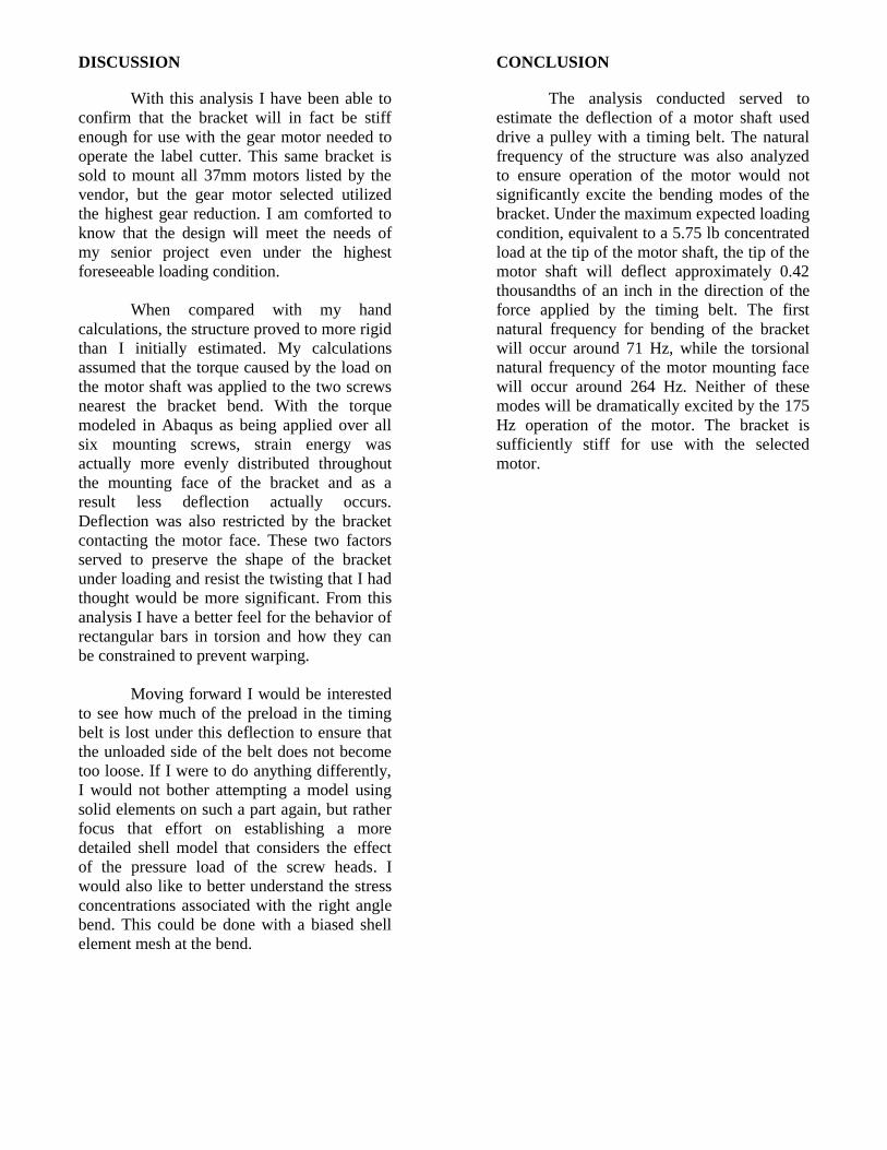
DISCUSSION
With this analysis I have been able to
confirm that the bracket will in fact be stiff
enough for use with the gear motor needed to
operate the label cutter. This same bracket is
sold to mount all 37mm motors listed by the
vendor, but the gear motor selected utilized
the highest gear reduction. I am comforted to
know that the design will meet the needs of
my senior project even under the highest
foreseeable loading condition.
When compared with my hand
calculations, the structure proved to more rigid
than I initially estimated. My calculations
assumed that the torque caused by the load on
the motor shaft was applied to the two screws
nearest the bracket bend. With the torque
modeled in Abaqus as being applied over all
six mounting screws, strain energy was
actually more evenly distributed throughout
the mounting face of the bracket and as a
result less deflection actually occurs.
Deflection was also restricted by the bracket
contacting the motor face. These two factors
served to preserve the shape of the bracket
under loading and resist the twisting that I had
thought would be more significant. From this
analysis I have a better feel for the behavior of
rectangular bars in torsion and how they can
be constrained to prevent warping.
Moving forward I would be interested
to see how much of the preload in the timing
belt is lost under this deflection to ensure that
the unloaded side of the belt does not become
too loose. If I were to do anything differently,
I would not bother attempting a model using
solid elements on such a part again, but rather
focus that effort on establishing a more
detailed shell model that considers the effect
of the pressure load of the screw heads. I
would also like to better understand the stress
concentrations associated with the right angle
bend. This could be done with a biased shell
element mesh at the bend.
CONCLUSION
The analysis conducted served to
estimate the deflection of a motor shaft used
drive a pulley with a timing belt. The natural
frequency of the structure was also analyzed
to ensure operation of the motor would not
significantly excite the bending modes of the
bracket. Under the maximum expected loading
condition, equivalent to a 5.75 lb concentrated
load at the tip of the motor shaft, the tip of the
motor shaft will deflect approximately 0.42
thousandths of an inch in the direction of the
force applied by the timing belt. The first
natural frequency for bending of the bracket
will occur around 71 Hz, while the torsional
natural frequency of the motor mounting face
will occur around 264 Hz. Neither of these
modes will be dramatically excited by the 175
Hz operation of the motor. The bracket is
sufficiently stiff for use with the selected
motor.

EZ‐Labels Inc. | Confidential‐ No unauthorized reproduction without a written agreement
58
AppendixF:ProjectPlanning

ID Task
Mode
Task Name Duration Start Finish Predecessors
1 Rough Cuts 7 days Mon 4/8/13 Tue 4/16/13
2 parts 100001 through 100011 (14 parts) 3 days Mon 4/8/13 Wed 4/10/13
3 parts 110001 through 112004 (10 parts) 2 days Thu 4/11/13 Fri 4/12/13 2
4 Parts 130002 through 160002 (8 parts) 2 days Mon 4/15/13 Tue 4/16/13
5 Fine cut parts and drill/tap holes 17 days? Mon 4/15/13 Tue 5/7/13
6 Fine cut parts and drill/tap holes 0 days? Tue 5/7/13 Tue 5/7/13
7 100001, 100002-1,100002-2 2 days Tue 4/16/13 Wed 4/17/13
8 140002-1,14000-2,100003 2 days Thu 4/18/13 Fri 4/19/13
9 100004, 110002, 100005 2 days Mon 4/15/13 Tue 4/16/13
10 100006,100008,100007 2 days Tue 4/16/13 Wed 4/17/13
11 100009,100010,10011 2 days Thu 4/18/13 Fri 4/19/13
12 110001,111001,111101 2 days Mon 4/22/13 Tue 4/23/13
13 112001,113001,112002 2 days Tue 4/23/13 Wed 4/24/13
14 112003, 112004,130002 2 days Thu 4/25/13 Fri 4/26/13
15 150002,150004,151001 2 days Mon 4/29/13 Tue 4/30/13
16 151001,151002,151003 2 days Tue 4/30/13 Wed 5/1/13
17 160001,160002,18000's 3 days Fri 5/3/13 Tue 5/7/13 16
18 Assembly 268 days?Wed 5/23/12 Thu 5/30/13
19 Assembly 0 days? Wed 5/8/13 Wed 5/8/13
20 Bottom plate assembly, Rail assembly 3 days Wed 5/23/12 Fri 5/25/12
21 Roller assembly, Cutter assembly 3 days Sat 5/11/13 Tue 5/14/13 20
22 Misc 0 days Thu 5/16/13 Thu 5/16/13 21
23 Testing and Troubleshooting 10 days Fri 5/17/13 Thu 5/30/13 22
M F T S W S
Mar 18, '12 Apr 1, '12
Task
Split
Milestone
Summary
Project Summary
Inactive Task
Inactive Milestone
Inactive Summary
Manual Task
Duration-only
Manual Summary Rollup
Manual Summary
Start-only
Finish-only
External Tasks
External Milestone
Deadline
Progress
Manual Progress
Page 1
Project: FirstLaunch
Date: Wed 4/10/13
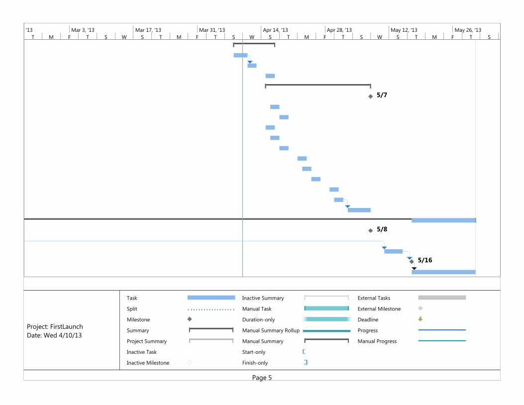
5/7
5/8
5/16
T M F T S W S T M F T S W S T M F T S W S T M F T S W
Feb 17, '13 Mar 3, '13 Mar 17, '13 Mar 31, '13 Apr 14, '13 Apr 28, '13 May 12, '13 May 26, '13
Task
Split
Milestone
Summary
Project Summary
Inactive Task
Inactive Milestone
Inactive Summary
Manual Task
Duration-only
Manual Summary Rollup
Manual Summary
Start-only
Finish-only
External Tasks
External Milestone
Deadline
Progress
Manual Progress
Page 5
Project: FirstLaunch
Date: Wed 4/10/13

EZ‐Labels Inc. | Confidential‐ No unauthorized reproduction without a written agreement
59
AppendixG:WiringDiagram


EZ‐Labels Inc. | Confidential‐ No unauthorized reproduction without a written agreement
60
AppendixH:MechatronicsCode
SeeFilesonincludedCD(Folder:CNCLabelCutter)