wear mechanisms of wc–10ni3al carbide tool in dry turning of ti6al4v
TRANSCRIPT

Int. Journal of Refractory Metals and Hard Materials 48 (2015) 272–285
Contents lists available at ScienceDirect
Int. Journal of Refractory Metals and Hard Materials
j ourna l homepage: www.e lsev ie r .com/ locate / IJRMHM
Wear mechanisms of WC–10Ni3Al carbide tool in dry turning of Ti6Al4V
Liang Liang, Xin Liu ⁎, Xiao-qiang Li, Yuan-Yuan LiCollege of Mechanical and Automotive Engineering, South China University of Technology, Guangzhou 510640, PR China
⁎ Corresponding author.E-mail address: [email protected] (X. Liu).
http://dx.doi.org/10.1016/j.ijrmhm.2014.09.0190263-4368/© 2014 Elsevier Ltd. All rights reserved.
a b s t r a c t
a r t i c l e i n f oArticle history:Received 30 May 2014Received in revised form 13 September 2014Accepted 19 September 2014Available online 20 September 2014
Keywords:CarbideNi3Al binderTi6Al4VWear mechanism
The current investigation studied the possible beneficial effect of Ni3Al binder onWC-based cemented carbides indry machining of a titanium alloy. The WC-10 wt.% Ni3Al carbide tool was prepared through spark plasmasintering (SPS) technique. The cutting performance and wear mechanism of WC–10Ni3Al in continuous turningof Ti6Al4V were also discussed by analyzing themorphologies and compositions of worn surfaces of the carbide.The commercial available WC–8Co has also been tested under the same conditions for the purpose of compari-son. The results showed that the WC–10Ni3Al has better cutting performance than WC–8Co, especially at thehigher cutting speed of vc = 100 m/min. The excellent crater and flank wear resistance of WC–10Ni3Al wasattributed to its synergistic mechanism of chemical inertness and high hardness induced by the intermetallicalloy Ni3Al binder at elevated temperature.
© 2014 Elsevier Ltd. All rights reserved.
1. Introduction
Titanium and titanium alloys are the most promising structural ma-terials for the products of the contemporary spacecraft engineering, air-craft, and medicine because of their high specific strength, fractureresistance, and corrosion resistance [1]. However, titanium alloys arealso known as difficult to machine materials. Cutting of titanium alloyswill cause extreme high temperature at the tool–chip interface due totheir high strength at elevated temperature and relative low thermalconductivity [2]. The maximum temperature at the tool–chip interfacewhen dry machining Ti6Al4V in high cutting speed can reach 1000 °C[3,4]. Moreover, titanium becomes highly reactive at elevated tempera-ture, whichwould cause severe adhesion on the cutting tool [5,6]. Thesecharacteristics are prone to induce excessive chipping and prematurefailure of the cutting tool and poor surface finish in titaniummachining[7].
Among the existing tool materials, WC–Co carbides are generallyregarded as a suitable tool material commercially available for titaniumalloy machining [8]. As for WC–Co carbide, the binder phase Co can fa-cilitate sintering and increase the strength and toughness considerably[9]. However, the addition of Co binder not only deteriorates hardnessand corrosion/oxidation resistance of materials but also decreases theelevated temperature strength [10]. When machining titanium alloyswith a WC–Co carbide tool, the Co binder is susceptible to diffuse fromthe tool materials to the titanium alloy through the tool–chip interface.The diffusion of Co element may lead to the strength reduction of thetool substrate, which increases the possibility of mechanical damage
of the cutting edge [11]. These properties greatly affect the cuttingperformance of the WC–Co cutting tool in titanium alloy machining,especially at high cutting speeds.
To overcome these deficiencies, the replacement of Co with otherbinder presents an effective choice [12], for example, by utilizing a duc-tile intermetallic alloy Ni3Al binder. Ni3Al has many attractive advan-tages necessary for superior wear resistance such as high hardness,high elastic modulus, high melting point, good oxidation and corrosionresistance [13]. Furthermore, the yield strength of Ni3Al increasessubstantially with increasing temperature up to 600–800 °C [14,15]. Inaddition, the Ni3Al phase was found to have a good wettability withWC grains, making it possible to obtain dense bulk WC–Ni3Al [16–18].Ni3Al is therefore a specially promising material needed in aggressiveenvironment at elevated temperature. The utilization of Ni3Al as thebinder material has great potential to improve the cutting performanceof the WC-based carbide in Ti6Al4V machining.
Many studies have been carried out in the preparation of WC–Ni3Alcarbides.M. Ahmadian et al. [19,20] have investigated the abrasivewearresistance of WC–Ni3Al with different amounts of boron and confirmedthat the abrasive wear resistance of WC-40 vol.% (Ni3Al-500 ppmB) composite is superior to that of WC-40 vol.% Co cemented carbides,which is attributed to the higher hardness of Ni3Al in comparison withCo. T.N. Tiegs et al. [21] produced a B-doped WC-17 vol.% Ni3Al alloyby hot pressing and reported that the flexural strength of the materialcan be retained to temperatures of at least 800 °C, its fracture toughnessand hardness were equal or higher than the comparable WC–Co. Basedon spark plasma sintering method, X.Q. Li et al. [22] developed a WC-10 wt.%Ni3Al carbide with plate-like triangular prismatic WC gains;the material prepared in the optimized sintering process possesses agood combination of hardness, transverse rupture strength and fracturetoughness.
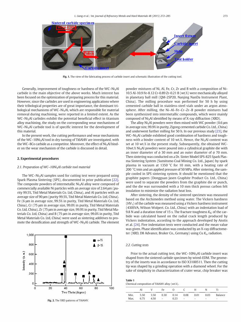
Fig. 1. The view of the fabricating process of carbide insert and schematic illustration of the cutting tool.
273L. Liang et al. / Int. Journal of Refractory Metals and Hard Materials 48 (2015) 272–285
Generally, improvement of toughness or hardness of the WC–Ni3Alcarbide is the main objective of the above works. Much interest hasbeen focused on the optimization of preparing process for this material.However, since the carbides are used in engineering applicationswheretheir tribological properties are of great importance, the dominant tri-bological mechanisms of WC–Ni3Al, which are responsible for materialremoval during machining, were reported in a limited extent. As theWC–Ni3Al carbides exhibit the potential beneficial effect in titaniumalloy machining, the study on the corresponding wear mechanisms ofWC–Ni3Al carbide tool is of specific interest for the development ofthis material.
In the present work, the cutting performance and wearmechanismsof the WC–10Ni3Al tool in dry turning of Ti6Al4V are investigated, withtheWC–8Co carbide as a competitor. Moreover, the effect of Ni3Al bind-er on the wear mechanism of the carbide is discussed in detail.
2. Experimental procedures
2.1. Preparation of WC–10Ni3Al carbide tool material
The WC–Ni3Al samples used for cutting test were prepared usingSpark Plasma Sintering (SPS), documented in prior publication [22].The composite powders of intermetallic Ni3Al alloy were composed ofcommercially available Ni particles with an average size of 2.64 μm(pu-rity 99.5%, Titd Metal Materials Co. Ltd, China), and Al particles with anaverage size of 90 μm(purity 99.5%, TitdMetal Materials Co. Ltd, China).Fe (6 μm in average size, 99.5% in purity, Titd Metal Materials Co. Ltd,China), Cr (75 μm in average size, 99.0% in purity, Titd Metal MaterialsCo. Ltd, China), Zr (75 μm in average size, 99.9% in purity, TitdMetalMa-terials Co. Ltd, China) and B (75 μm in average size, 99.0% in purity, TitdMetal Materials Co. Ltd, China) were used as sintering additives to pro-mote the densification and strength of WC–Ni3Al carbide. The element
Fig. 2. The XRD patterns of Ti6Al4V.
powder mixtures of Ni, Al, Fe, Cr, Zr and B with a composition of Ni-10.5 Al-10.9 Fe-8.12 Cr-0.89 Zr-0.21 B (wt.%)weremechanically alloyedin planetary ball mill (QM-2SP20, Nanjing NanDa Instrument Plant,China). The milling procedure was performed for 50 h by usingcemented carbide ball in stainless-steel vials under an argon atmo-sphere. After milling, the Ni–Al–Fe–Cr–Zr–B powder mixtures hadbeen synthesized into intermetallic compounds, which were mainlycomposed of Ni3Al identified by means of X-ray diffraction (XRD).
The alloy Ni3Al powders were then mixed withWC powder (0.6 μmin average size, 99.9% in purity, Zigong cemented carbide Co. Ltd., China)and underwent further milling for 50 h. In our previous study [23], theWC–Ni3Al carbide exhibited good combination of hardness and tough-ness with a binder content of 10 wt.%. Hence, the Ni3Al content wasset at 10 wt.% in the present study. Subsequently, the obtained WC-10wt.% Ni3Al powders were poured into a cylindrical graphite die withan inner diameter of ϕ 30 mm and an outer diameter of ϕ 70 mm.Then sinteringwas conducted on a Dr. SinterModel SPS-825 Spark Plas-ma Sintering System (Sumitomo Coal Mining Co. Ltd., Japan) by sparkplasma in vacuum at 1350 °C for 10 min, with a heating rate of200 °C/min and an applied pressure of 50MPa. After sintering, the sam-ple cooled in SPS sintering system. It should be mentioned that thegraphite papers (Dongguan Jasen Graphite Product Co. Ltd., China)were used to separate the powders from the graphite die or punch,and the die was surrounded with a 10 mm thick porous carbon feltinsulation to minimize the radiation heat loss.
After sintering, the density of the sintered specimen was measuredbased on the Archimedes method using water. The Vickers hardness(HV1) of the carbidewasmeasured using a Vickers hardness instrument(430SVA, Wilson Wolpert. Co. Ltd., China) with an indentation load of9.8 N and a duration time of 15 s. The fracture toughness KIC of the car-bide was calculated based on the radial crack length produced byVickers indentation, according to the approach developed by Anstiset al. [24]. Five indentation tests were conducted and the mean valuewas given. Phase identification was conducted by an X-ray diffractome-ter (XRD, D8 Advance, Bruker Co., Germany) using Cu Kα radiation.
2.2. Cutting tests
Prior to the actual cutting test, the WC–10Ni3Al carbide insert wasshaped from the sintered carbide specimen by wired-EDM. The geome-try of the inserts was in accordance to ISO X3100511. Then the cuttingtip was shaped by a grinding operation with a diamond wheel. For thesake of simplicity in characterization of crater wear, chip breaker was
Table 1Chemical composition of Ti6Al4V alloy (wt.%).
Al V Fe O C H N Ti
Min. 5.50 3.50 0.30 0.14 0.08 0.01 0.03 BalanceMax. 6.75 4.50 – 0.23 – – – –
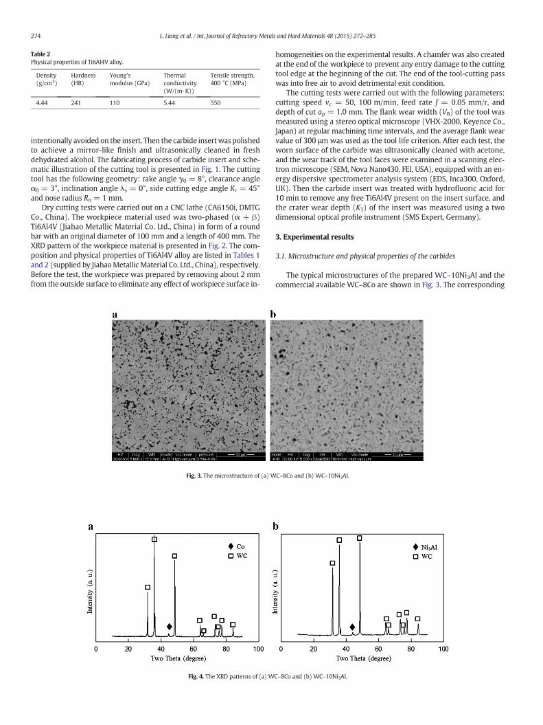
Table 2Physical properties of Ti6Al4V alloy.
Density(g/cm3)
Hardness(HB)
Young'smodulus (GPa)
Thermalconductivity(W/(m·K))
Tensile strength,400 °C (MPa)
4.44 241 110 5.44 550
274 L. Liang et al. / Int. Journal of Refractory Metals and Hard Materials 48 (2015) 272–285
intentionally avoided on the insert. Then the carbide insertwaspolishedto achieve a mirror-like finish and ultrasonically cleaned in freshdehydrated alcohol. The fabricating process of carbide insert and sche-matic illustration of the cutting tool is presented in Fig. 1. The cuttingtool has the following geometry: rake angle γ0 = 8°, clearance angleα0 = 3°, inclination angle λs = 0°, side cutting edge angle Kr = 45°and nose radius Rn = 1 mm.
Dry cutting tests were carried out on a CNC lathe (CA6150i, DMTGCo., China). The workpiece material used was two-phased (α + β)Ti6Al4V (Jiahao Metallic Material Co. Ltd., China) in form of a roundbar with an original diameter of 100 mm and a length of 400 mm. TheXRD pattern of the workpiece material is presented in Fig. 2. The com-position and physical properties of Ti6Al4V alloy are listed in Tables 1and 2 (supplied by JiahaoMetallicMaterial Co. Ltd., China), respectively.Before the test, the workpiece was prepared by removing about 2 mmfrom the outside surface to eliminate any effect of workpiece surface in-
Fig. 3. The microstructure of (a) W
Fig. 4. The XRD patterns of (a) W
homogeneities on the experimental results. A chamfer was also createdat the end of the workpiece to prevent any entry damage to the cuttingtool edge at the beginning of the cut. The end of the tool-cutting passwas into free air to avoid detrimental exit condition.
The cutting tests were carried out with the following parameters:cutting speed vc = 50, 100 m/min, feed rate f = 0.05 mm/r, anddepth of cut ap = 1.0 mm. The flank wear width (VB) of the tool wasmeasured using a stereo optical microscope (VHX-2000, Keyence Co.,Japan) at regular machining time intervals, and the average flank wearvalue of 300 μm was used as the tool life criterion. After each test, theworn surface of the carbide was ultrasonically cleaned with acetone,and the wear track of the tool faces were examined in a scanning elec-tron microscope (SEM, Nova Nano430, FEI, USA), equipped with an en-ergy dispersive spectrometer analysis system (EDS, Inca300, Oxford,UK). Then the carbide insert was treated with hydrofluoric acid for10 min to remove any free Ti6Al4V present on the insert surface, andthe crater wear depth (KT) of the insert was measured using a twodimensional optical profile instrument (SMS Expert, Germany).
3. Experimental results
3.1. Microstructure and physical properties of the carbides
The typical microstructures of the prepared WC–10Ni3Al and thecommercial available WC–8Co are shown in Fig. 3. The corresponding
C–8Co and (b) WC–10Ni3Al.
C–8Co and (b) WC–10Ni3Al.
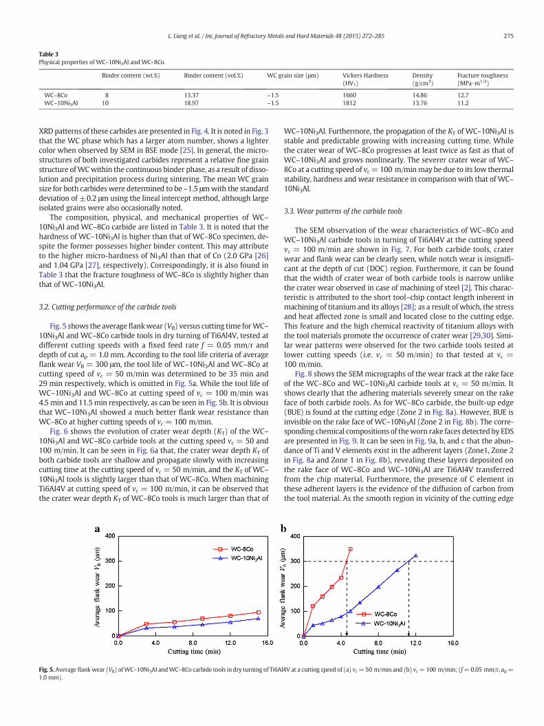
Table 3Physical properties of WC–10Ni3Al and WC–8Co.
Binder content (wt.%) Binder content (vol.%) WC grain size (μm) Vickers Hardness(HV1)
Density(g/cm3)
Fracture toughness(MPa·m1/2)
WC–8Co 8 13.37 ~1.5 1660 14.86 12.7WC–10Ni3Al 10 18.97 ~1.5 1812 13.76 11.2
275L. Liang et al. / Int. Journal of Refractory Metals and Hard Materials 48 (2015) 272–285
XRD patterns of these carbides are presented in Fig. 4. It is noted in Fig. 3that the WC phase which has a larger atom number, shows a lightercolor when observed by SEM in BSE mode [25]. In general, the micro-structures of both investigated carbides represent a relative fine grainstructure ofWCwithin the continuous binder phase, as a result of disso-lution and precipitation process during sintering. The mean WC grainsize for both carbides were determined to be ~1.5 μmwith the standarddeviation of ±0.2 μm using the lineal intercept method, although largeisolated grains were also occasionally noted.
The composition, physical, and mechanical properties of WC–10Ni3Al and WC–8Co carbide are listed in Table 3. It is noted that thehardness of WC–10Ni3Al is higher than that of WC–8Co specimen, de-spite the former possesses higher binder content. This may attributeto the higher micro-hardness of Ni3Al than that of Co (2.0 GPa [26]and 1.04 GPa [27], respectively). Correspondingly, it is also found inTable 3 that the fracture toughness of WC–8Co is slightly higher thanthat of WC–10Ni3Al.
3.2. Cutting performance of the carbide tools
Fig. 5 shows the averageflankwear (VB) versus cutting time forWC–10Ni3Al and WC–8Co carbide tools in dry turning of Ti6Al4V, tested atdifferent cutting speeds with a fixed feed rate f = 0.05 mm/r anddepth of cut ap = 1.0 mm. According to the tool life criteria of averageflank wear VB = 300 μm, the tool life of WC–10Ni3Al and WC–8Co atcutting speed of vc = 50 m/min was determined to be 35 min and29 min respectively, which is omitted in Fig. 5a. While the tool life ofWC–10Ni3Al and WC–8Co at cutting speed of vc = 100 m/min was4.5 min and 11.5min respectively, as can be seen in Fig. 5b. It is obviousthat WC–10Ni3Al showed a much better flank wear resistance thanWC–8Co at higher cutting speeds of vc = 100 m/min.
Fig. 6 shows the evolution of crater wear depth (KT) of the WC–10Ni3Al and WC–8Co carbide tools at the cutting speed vc = 50 and100 m/min. It can be seen in Fig. 6a that, the crater wear depth KT ofboth carbide tools are shallow and propagate slowly with increasingcutting time at the cutting speed of vc = 50 m/min, and the KT of WC–10Ni3Al tools is slightly larger than that of WC–8Co. When machiningTi6Al4V at cutting speed of vc = 100 m/min, it can be observed thatthe crater wear depth KT of WC–8Co tools is much larger than that of
Fig. 5.Average flankwear (VB) ofWC–10Ni3Al andWC–8Co carbide tools in dry turning of Ti6Al1.0 mm).
WC–10Ni3Al. Furthermore, the propagation of the KT of WC–10Ni3Al isstable and predictable growing with increasing cutting time. Whilethe crater wear of WC–8Co progresses at least twice as fast as that ofWC–10Ni3Al and grows nonlinearly. The severer crater wear of WC–8Co at a cutting speed of vc=100 m/minmay be due to its low thermalstability, hardness and wear resistance in comparison with that of WC–10Ni3Al.
3.3. Wear patterns of the carbide tools
The SEM observation of the wear characteristics of WC–8Co andWC–10Ni3Al carbide tools in turning of Ti6Al4V at the cutting speedvc = 100 m/min are shown in Fig. 7. For both carbide tools, craterwear and flank wear can be clearly seen, while notch wear is insignifi-cant at the depth of cut (DOC) region. Furthermore, it can be foundthat the width of crater wear of both carbide tools is narrow unlikethe crater wear observed in case of machining of steel [2]. This charac-teristic is attributed to the short tool–chip contact length inherent inmachining of titanium and its alloys [28]; as a result of which, the stressand heat affected zone is small and located close to the cutting edge.This feature and the high chemical reactivity of titanium alloys withthe tool materials promote the occurrence of crater wear [29,30]. Simi-lar wear patterns were observed for the two carbide tools tested atlower cutting speeds (i.e. vc = 50 m/min) to that tested at vc =100 m/min.
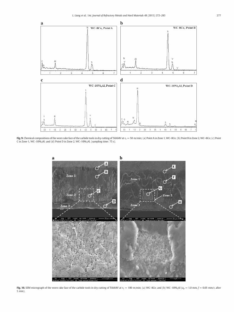
Fig. 8 shows the SEMmicrographs of the wear track at the rake faceof the WC–8Co and WC–10Ni3Al carbide tools at vc = 50 m/min. Itshows clearly that the adhering materials severely smear on the rakeface of both carbide tools. As for WC–8Co carbide, the built-up edge(BUE) is found at the cutting edge (Zone 2 in Fig. 8a). However, BUE isinvisible on the rake face of WC–10Ni3Al (Zone 2 in Fig. 8b). The corre-sponding chemical compositions of theworn rake faces detected by EDSare presented in Fig. 9. It can be seen in Fig. 9a, b, and c that the abun-dance of Ti and V elements exist in the adherent layers (Zone1, Zone 2in Fig. 8a and Zone 1 in Fig. 8b), revealing these layers deposited onthe rake face of WC–8Co and WC–10Ni3Al are Ti6Al4V transferredfrom the chip material. Furthermore, the presence of C element inthese adherent layers is the evidence of the diffusion of carbon fromthe tool material. As the smooth region in vicinity of the cutting edge
4V at a cutting speed of (a) vc=50 m/min and (b) vc=100 m/min; (f=0.05 mm/r, ap=
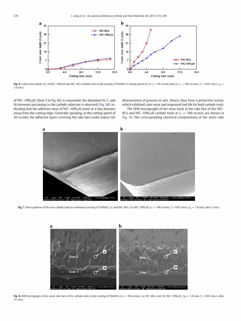
Fig. 6. Crater wear depth (KT) of WC–10Ni3Al andWC–8Co carbide tools in dry turning of Ti6Al4V at cutting speed of (a) vc = 50 m/min and (b) vc = 100 m/min; (f=0.05 mm/r, ap =1.0 mm).
276 L. Liang et al. / Int. Journal of Refractory Metals and Hard Materials 48 (2015) 272–285
ofWC–10Ni3Al (Zone 2 in Fig. 8b) is concerned, the abundantW, C, andNi elements pertaining to the carbide substrate is observed (Fig. 9d) in-dicating that the adhesive wear of WC–10Ni3Al starts at a tiny distanceaway from the cutting edge. Generally speaking, at the cutting speed of50 m/min, the adherent layers covering the rake face could reduce the
Fig. 7.Wear patterns of the two carbide tools in continuous turning of Ti6Al4V, (a) and WC
Fig. 8. SEM micrograph of the worn rake face of the carbide tools in dry cutting of Ti6Al4V at15 min).
deterioration of grooves or pits. Hence, they have a protective action,which inhibited caterwear and improved tool life for both carbide tools.
The SEM micrographs of the wear track at the rake face of the WC–8Co and WC–10Ni3Al carbide tools at vc = 100 m/min are shown inFig. 10. The corresponding chemical compositions of the worn rake
–8Co, (b) WC–10Ni3Al (vc = 100 m/min, f = 0.05 mm/r, ap = 1.0 mm, after 5 min).
vc = 50 m/min; (a) WC–8Co; and (b) WC–10Ni3Al; (ap = 1.0 mm, f = 0.05 mm/r, after
a b
c d
Fig. 9.Chemical compositions of theworn rake face of the carbide tools in dry cutting of Ti6Al4V at vc=50 m/min; (a) Point A in Zone 1,WC–8Co; (b) Point B in Zone 2,WC–8Co; (c) PointC in Zone 1, WC–10Ni3Al; and (d) Point D in Zone 2, WC–10Ni3Al. (sampling time: 75 s).
Fig. 10. SEM micrograph of the worn rake face of the carbide tools in dry cutting of Ti6Al4V at vc = 100 m/min; (a) WC–8Co; and (b) WC–10Ni3Al (ap = 1.0 mm, f = 0.05 mm/r, after5 min).
277L. Liang et al. / Int. Journal of Refractory Metals and Hard Materials 48 (2015) 272–285
a b
c d
e f
g h
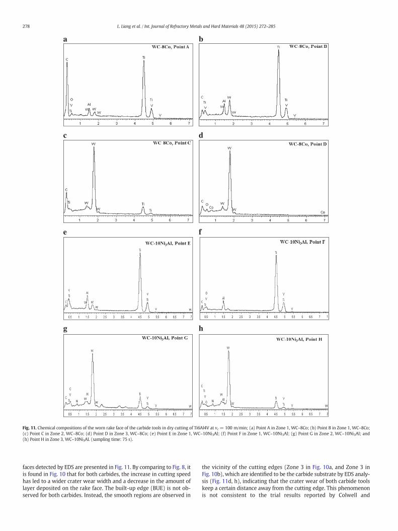
Fig. 11. Chemical compositions of the worn rake face of the carbide tools in dry cutting of Ti6Al4V at vc = 100 m/min; (a) Point A in Zone 1, WC–8Co; (b) Point B in Zone 1, WC–8Co;(c) Point C in Zone 2, WC–8Co; (d) Point D in Zone 3, WC–8Co; (e) Point E in Zone 1, WC–10Ni3Al; (f) Point F in Zone 1, WC–10Ni3Al; (g) Point G in Zone 2, WC–10Ni3Al; and(h) Point H in Zone 3, WC–10Ni3Al. (sampling time: 75 s).
278 L. Liang et al. / Int. Journal of Refractory Metals and Hard Materials 48 (2015) 272–285
faces detected by EDS are presented in Fig. 11. By comparing to Fig. 8, itis found in Fig. 10 that for both carbides, the increase in cutting speedhas led to a wider crater wear width and a decrease in the amount oflayer deposited on the rake face. The built-up edge (BUE) is not ob-served for both carbides. Instead, the smooth regions are observed in
the vicinity of the cutting edges (Zone 3 in Fig. 10a, and Zone 3 inFig. 10b), which are identified to be the carbide substrate by EDS analy-sis (Fig. 11d, h), indicating that the crater wear of both carbide toolskeep a certain distance away from the cutting edge. This phenomenonis not consistent to the trial results reported by Colwell and
a b
c d
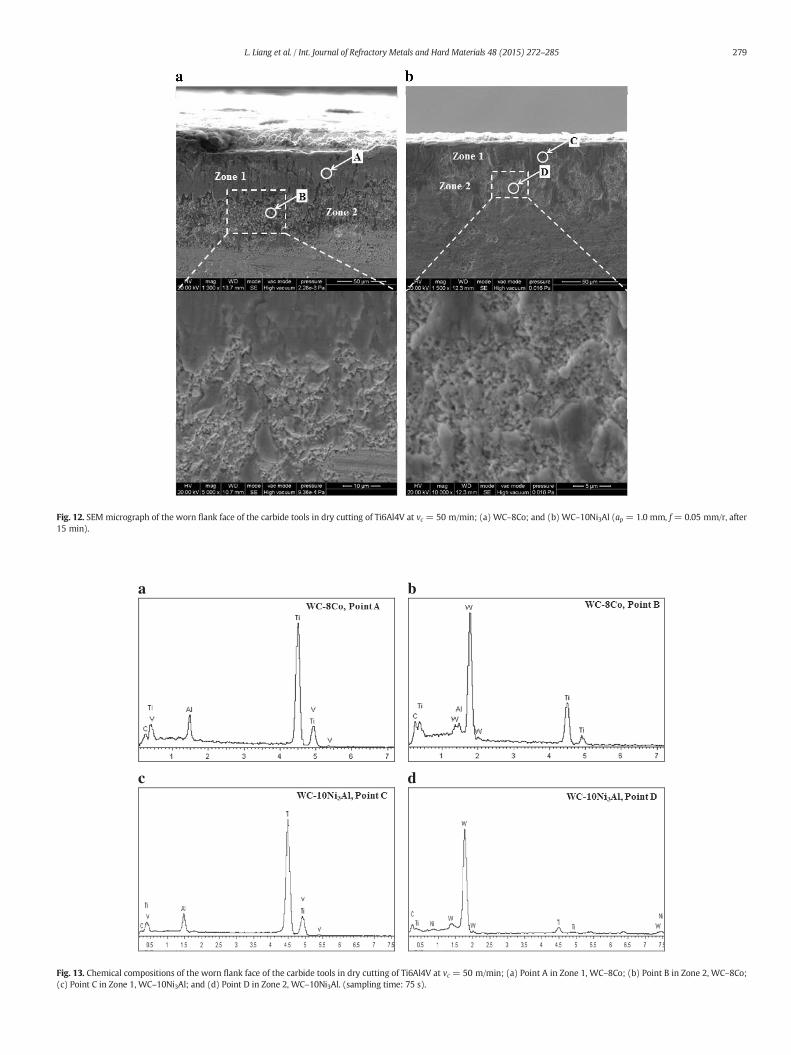
Fig. 13. Chemical compositions of the worn flank face of the carbide tools in dry cutting of Ti6Al4V at vc = 50 m/min; (a) Point A in Zone 1, WC–8Co; (b) Point B in Zone 2, WC–8Co;(c) Point C in Zone 1, WC–10Ni3Al; and (d) Point D in Zone 2, WC–10Ni3Al. (sampling time: 75 s).
Fig. 12. SEM micrograph of the worn flank face of the carbide tools in dry cutting of Ti6Al4V at vc = 50 m/min; (a) WC–8Co; and (b) WC–10Ni3Al (ap = 1.0 mm, f = 0.05 mm/r, after15 min).
279L. Liang et al. / Int. Journal of Refractory Metals and Hard Materials 48 (2015) 272–285
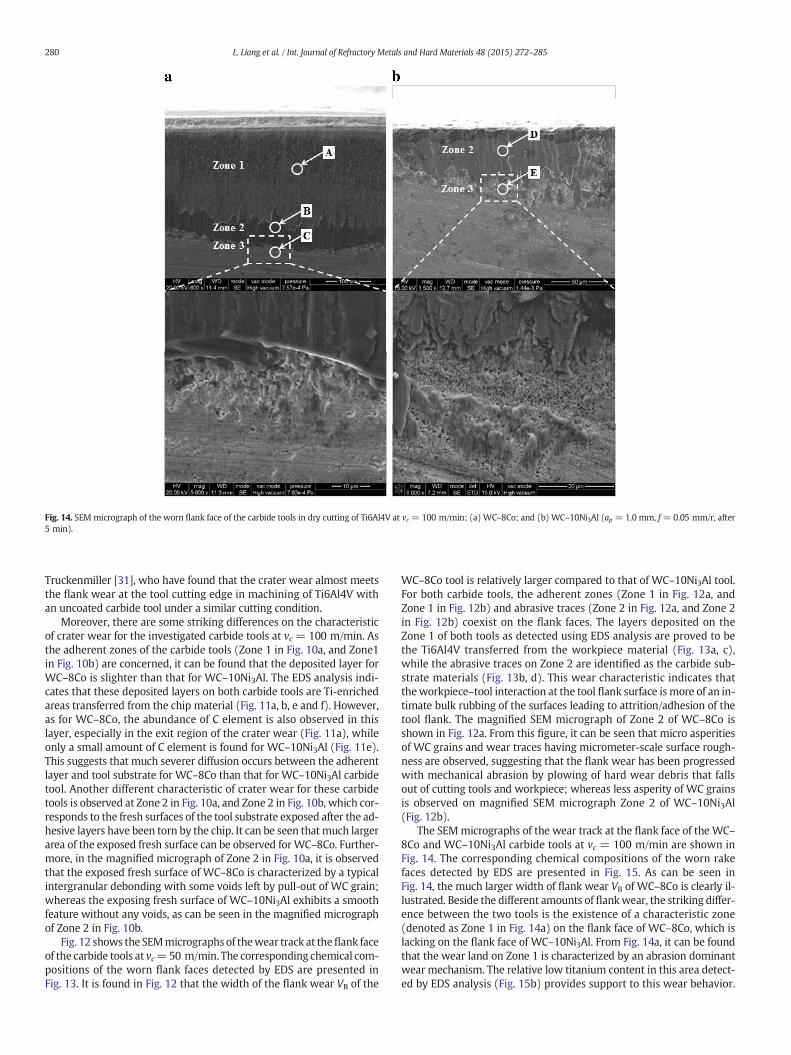
Fig. 14. SEM micrograph of the worn flank face of the carbide tools in dry cutting of Ti6Al4V at vc = 100 m/min; (a) WC–8Co; and (b) WC–10Ni3Al (ap = 1.0 mm, f = 0.05 mm/r, after5 min).
280 L. Liang et al. / Int. Journal of Refractory Metals and Hard Materials 48 (2015) 272–285
Truckenmiller [31], who have found that the crater wear almost meetsthe flank wear at the tool cutting edge in machining of Ti6Al4V withan uncoated carbide tool under a similar cutting condition.
Moreover, there are some striking differences on the characteristicof crater wear for the investigated carbide tools at vc = 100 m/min. Asthe adherent zones of the carbide tools (Zone 1 in Fig. 10a, and Zone1in Fig. 10b) are concerned, it can be found that the deposited layer forWC–8Co is slighter than that for WC–10Ni3Al. The EDS analysis indi-cates that these deposited layers on both carbide tools are Ti-enrichedareas transferred from the chip material (Fig. 11a, b, e and f). However,as for WC–8Co, the abundance of C element is also observed in thislayer, especially in the exit region of the crater wear (Fig. 11a), whileonly a small amount of C element is found for WC–10Ni3Al (Fig. 11e).This suggests that much severer diffusion occurs between the adherentlayer and tool substrate for WC–8Co than that for WC–10Ni3Al carbidetool. Another different characteristic of crater wear for these carbidetools is observed at Zone 2 in Fig. 10a, and Zone 2 in Fig. 10b, which cor-responds to the fresh surfaces of the tool substrate exposed after the ad-hesive layers have been torn by the chip. It can be seen that much largerarea of the exposed fresh surface can be observed forWC–8Co. Further-more, in the magnified micrograph of Zone 2 in Fig. 10a, it is observedthat the exposed fresh surface of WC–8Co is characterized by a typicalintergranular debonding with some voids left by pull-out of WC grain;whereas the exposing fresh surface of WC–10Ni3Al exhibits a smoothfeature without any voids, as can be seen in the magnified micrographof Zone 2 in Fig. 10b.
Fig. 12 shows the SEMmicrographs of thewear track at theflank faceof the carbide tools at vc=50 m/min. The corresponding chemical com-positions of the worn flank faces detected by EDS are presented inFig. 13. It is found in Fig. 12 that the width of the flank wear VB of the
WC–8Co tool is relatively larger compared to that of WC–10Ni3Al tool.For both carbide tools, the adherent zones (Zone 1 in Fig. 12a, andZone 1 in Fig. 12b) and abrasive traces (Zone 2 in Fig. 12a, and Zone 2in Fig. 12b) coexist on the flank faces. The layers deposited on theZone 1 of both tools as detected using EDS analysis are proved to bethe Ti6Al4V transferred from the workpiece material (Fig. 13a, c),while the abrasive traces on Zone 2 are identified as the carbide sub-strate materials (Fig. 13b, d). This wear characteristic indicates thattheworkpiece–tool interaction at the tool flank surface is more of an in-timate bulk rubbing of the surfaces leading to attrition/adhesion of thetool flank. The magnified SEM micrograph of Zone 2 of WC–8Co isshown in Fig. 12a. From this figure, it can be seen that micro asperitiesof WC grains and wear traces having micrometer-scale surface rough-ness are observed, suggesting that the flank wear has been progressedwith mechanical abrasion by plowing of hard wear debris that fallsout of cutting tools and workpiece; whereas less asperity of WC grainsis observed on magnified SEM micrograph Zone 2 of WC–10Ni3Al(Fig. 12b).
The SEMmicrographs of the wear track at the flank face of the WC–8Co and WC–10Ni3Al carbide tools at vc = 100 m/min are shown inFig. 14. The corresponding chemical compositions of the worn rakefaces detected by EDS are presented in Fig. 15. As can be seen inFig. 14, the much larger width of flank wear VB of WC–8Co is clearly il-lustrated. Beside the different amounts of flankwear, the striking differ-ence between the two tools is the existence of a characteristic zone(denoted as Zone 1 in Fig. 14a) on the flank face of WC–8Co, which islacking on the flank face of WC–10Ni3Al. From Fig. 14a, it can be foundthat the wear land on Zone 1 is characterized by an abrasion dominantwear mechanism. The relative low titanium content in this area detect-ed by EDS analysis (Fig. 15b) provides support to this wear behavior.
a b
c
e
d
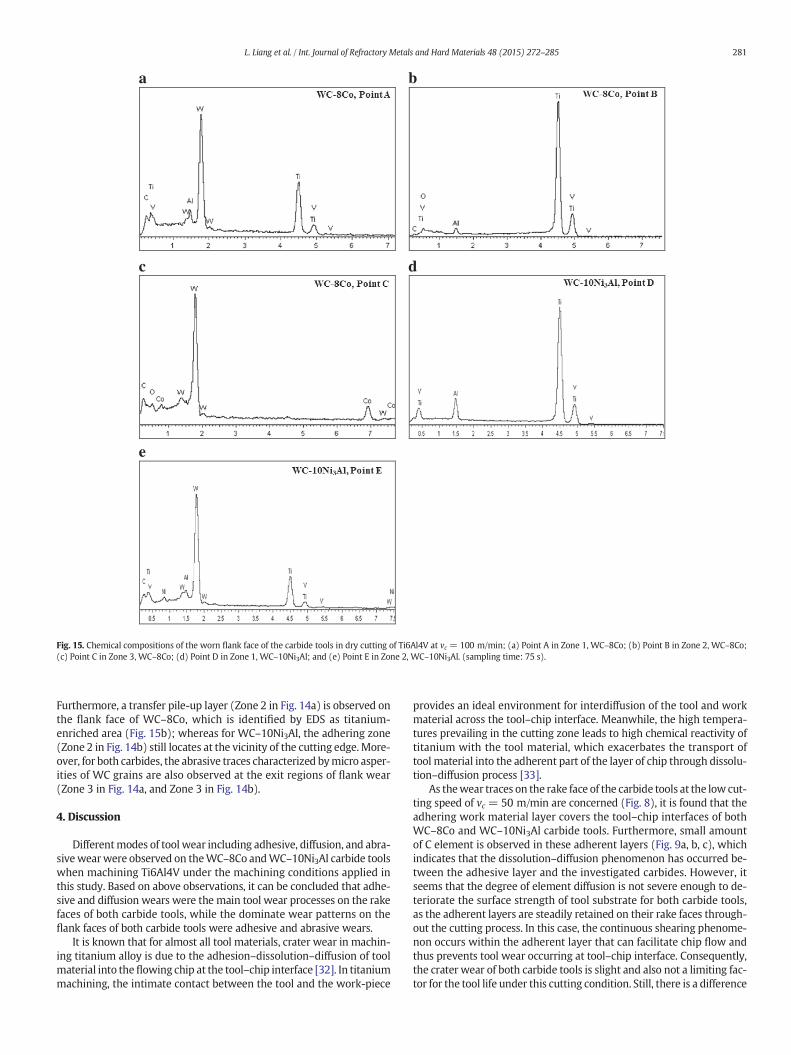
Fig. 15. Chemical compositions of the worn flank face of the carbide tools in dry cutting of Ti6Al4V at vc = 100 m/min; (a) Point A in Zone 1, WC–8Co; (b) Point B in Zone 2, WC–8Co;(c) Point C in Zone 3, WC–8Co; (d) Point D in Zone 1, WC–10Ni3Al; and (e) Point E in Zone 2, WC–10Ni3Al. (sampling time: 75 s).
281L. Liang et al. / Int. Journal of Refractory Metals and Hard Materials 48 (2015) 272–285
Furthermore, a transfer pile-up layer (Zone 2 in Fig. 14a) is observed onthe flank face of WC–8Co, which is identified by EDS as titanium-enriched area (Fig. 15b); whereas for WC–10Ni3Al, the adhering zone(Zone 2 in Fig. 14b) still locates at the vicinity of the cutting edge.More-over, for both carbides, the abrasive traces characterized bymicro asper-ities of WC grains are also observed at the exit regions of flank wear(Zone 3 in Fig. 14a, and Zone 3 in Fig. 14b).
4. Discussion
Differentmodes of tool wear including adhesive, diffusion, and abra-sivewearwere observed on theWC–8Co andWC–10Ni3Al carbide toolswhen machining Ti6Al4V under the machining conditions applied inthis study. Based on above observations, it can be concluded that adhe-sive and diffusion wears were the main tool wear processes on the rakefaces of both carbide tools, while the dominate wear patterns on theflank faces of both carbide tools were adhesive and abrasive wears.
It is known that for almost all tool materials, crater wear in machin-ing titanium alloy is due to the adhesion–dissolution–diffusion of toolmaterial into theflowing chip at the tool–chip interface [32]. In titaniummachining, the intimate contact between the tool and the work-piece
provides an ideal environment for interdiffusion of the tool and workmaterial across the tool–chip interface. Meanwhile, the high tempera-tures prevailing in the cutting zone leads to high chemical reactivity oftitanium with the tool material, which exacerbates the transport oftool material into the adherent part of the layer of chip through dissolu-tion–diffusion process [33].
As thewear traces on the rake face of the carbide tools at the low cut-ting speed of vc = 50 m/min are concerned (Fig. 8), it is found that theadhering work material layer covers the tool–chip interfaces of bothWC–8Co and WC–10Ni3Al carbide tools. Furthermore, small amountof C element is observed in these adherent layers (Fig. 9a, b, c), whichindicates that the dissolution–diffusion phenomenon has occurred be-tween the adhesive layer and the investigated carbides. However, itseems that the degree of element diffusion is not severe enough to de-teriorate the surface strength of tool substrate for both carbide tools,as the adherent layers are steadily retained on their rake faces through-out the cutting process. In this case, the continuous shearing phenome-non occurs within the adherent layer that can facilitate chip flow andthus prevents tool wear occurring at tool–chip interface. Consequently,the crater wear of both carbide tools is slight and also not a limiting fac-tor for the tool life under this cutting condition. Still, there is a difference
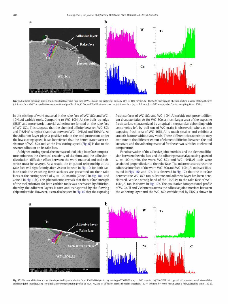
Fig. 16. Element diffusion across the deposited layer and rake face ofWC–8Co in dry cutting of Ti6Al4V at vc=100 m/min. (a) The SEMmicrograph of cross-sectional viewof the adhesivejoint interface. (b) The qualitative compositional profile of W, C, Co, and Ti diffusion across the joint interface (ap = 1.0 mm, f = 0.05 mm/r, after 5 min, sampling time: 150 s).
282 L. Liang et al. / Int. Journal of Refractory Metals and Hard Materials 48 (2015) 272–285
in the sticking of work material in the rake face of WC–8Co and WC–10Ni3Al carbide tools. Comparing to WC–10Ni3Al, the built-up-edge(BUE) and more work material adhesion are formed on the rake faceof WC–8Co. This suggests that the chemical affinity between WC–8Coand Ti6Al4V is higher than that between WC–10Ni3Al and Ti6Al4V. Asthe adherent layer plays a positive role in the tool protection underthe low cutting speed, it can be referred that the better crater wear re-sistance of WC–8Co tool at the low cutting speed (Fig. 6) is due to theseverer adhesion on its rake face.
At higher cutting speed, the increase of tool–chip interface tempera-ture enhances the chemical reactivity of titanium, and the adhesion–dissolution–diffusion effect between the work material and tool sub-strate must be severer. As a result, the chip/tool relationship at therake face will significantly alter. As can be seen in Fig. 10, for both car-bide tools the exposing fresh surfaces are presented on their rakefaces at the cutting speed of vc = 100 m/min (Zone 2 in Fig. 10a, andZone 2 in Fig. 10b). This phenomenon reveals that the surface strengthof the tool substrate for both carbide tools was decreased by diffusion,thereby the adherent layers is torn and transported by the flowingchip under side. However, it can also be seen in Fig. 10 that the exposing
Fig. 17. Element diffusion across the deposited layer and rake face of WC–10Ni3Al in dry cuttiadhesive joint interface. (b) The qualitative compositional profile of W, C, Ni, and Ti diffusion a
fresh surfaces of WC–8Co and WC–10Ni3Al carbide tool present differ-ent characteristics. As for WC–8Co, a much larger area of the exposingfresh surface characterized by a typical intergranular debonding withsome voids left by pull-out of WC grain is observed; whereas, theexposing fresh area of WC–10Ni3Al is much smaller and exhibits asmooth feature without any voids. These different characteristics mayattribute to the different extent of element diffusion between the toolsubstrate and the adhering material for these two carbides at elevatedtemperature.
For observation of the adhesive joint interface and the element diffu-sion between the rake face and the adheringmaterial at cutting speed ofvc = 100 m/min, the worn WC–8Co and WC–10Ni3Al tools weresectioned perpendicular to the rake face. The microstructures near theadhesive interface of thewornWC–8Co andWC–10Ni3Al tools are illus-trated in Figs. 16a and 17a. It is observed in Fig. 17a that the interfacebetween the WC–8Co tool substrate and adhesive layer has been dete-riorated. While a strong bond of the Ti6Al4V to the rake face of WC–10Ni3Al tool is shown in Fig. 17a. The qualitative compositional profileof W, Co, Ti and V elements across the adhesive joint interface betweenthe adhering layer and the WC–8Co carbide tool by EDS is shown in
ng of Ti6Al4V at vc = 100 m/min. (a) The SEM micrograph of cross-sectional view of thecross the joint interface. (ap = 1.0 mm, f= 0.05 mm/r, after 5 min, sampling time: 150 s).
Ti6Al4V
WC-8CoTool substrate
Adhesive layer
Chip
Cutting direction
noitceri dgni dil SPull-out of WC grain
Ti6Al4V
WC-8CoTool substrate
Adhesive layer
Chip
Cutting direction
noitceri dgni dil SUneven voids
Ti6Al4V
WC-8CoTool substrate
Adhesive layer
Chip
Cutting direction
noitceri dgni dil SSevere element diffusion
of the Co binder Ti6Al4V
WC-10Ni3AlTool substrate
Adhesive layer
Chip
Cutting direction
noitceri dgni dil SSlight element diffusion
of the Ni3Al binder
Ti6Al4V
WC-10Ni3AlTool substrate
Adhesive layer
Chip
Cutting direction
noitceri dgni dil SShear within the adherent layer
Ti6Al4V
WC-10Ni3AlTool substrate
Adhesive layer
Chip
Cutting direction
noitceri dgni dil SAct as a protective layer
a b
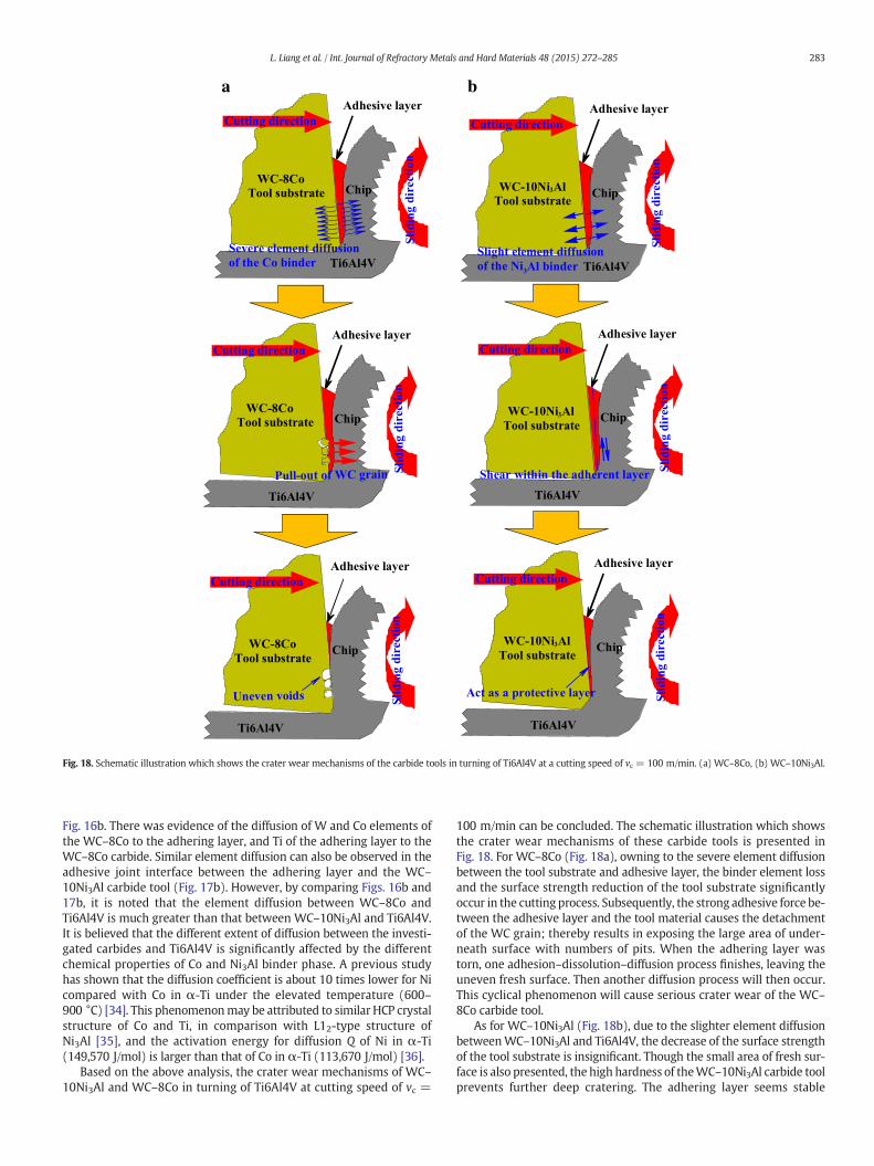
Fig. 18. Schematic illustration which shows the crater wear mechanisms of the carbide tools in turning of Ti6Al4V at a cutting speed of vc = 100 m/min. (a) WC–8Co, (b) WC–10Ni3Al.
283L. Liang et al. / Int. Journal of Refractory Metals and Hard Materials 48 (2015) 272–285
Fig. 16b. There was evidence of the diffusion of W and Co elements ofthe WC–8Co to the adhering layer, and Ti of the adhering layer to theWC–8Co carbide. Similar element diffusion can also be observed in theadhesive joint interface between the adhering layer and the WC–10Ni3Al carbide tool (Fig. 17b). However, by comparing Figs. 16b and17b, it is noted that the element diffusion between WC–8Co andTi6Al4V is much greater than that between WC–10Ni3Al and Ti6Al4V.It is believed that the different extent of diffusion between the investi-gated carbides and Ti6Al4V is significantly affected by the differentchemical properties of Co and Ni3Al binder phase. A previous studyhas shown that the diffusion coefficient is about 10 times lower for Nicompared with Co in α-Ti under the elevated temperature (600–900 °C) [34]. This phenomenonmay be attributed to similar HCP crystalstructure of Co and Ti, in comparison with L12-type structure ofNi3Al [35], and the activation energy for diffusion Q of Ni in α-Ti(149,570 J/mol) is larger than that of Co in α-Ti (113,670 J/mol) [36].
Based on the above analysis, the crater wear mechanisms of WC–10Ni3Al and WC–8Co in turning of Ti6Al4V at cutting speed of vc =
100 m/min can be concluded. The schematic illustration which showsthe crater wear mechanisms of these carbide tools is presented inFig. 18. For WC–8Co (Fig. 18a), owning to the severe element diffusionbetween the tool substrate and adhesive layer, the binder element lossand the surface strength reduction of the tool substrate significantlyoccur in the cutting process. Subsequently, the strong adhesive force be-tween the adhesive layer and the tool material causes the detachmentof the WC grain; thereby results in exposing the large area of under-neath surface with numbers of pits. When the adhering layer wastorn, one adhesion–dissolution–diffusion process finishes, leaving theuneven fresh surface. Then another diffusion process will then occur.This cyclical phenomenon will cause serious crater wear of the WC–8Co carbide tool.
As for WC–10Ni3Al (Fig. 18b), due to the slighter element diffusionbetweenWC–10Ni3Al and Ti6Al4V, the decrease of the surface strengthof the tool substrate is insignificant. Though the small area of fresh sur-face is also presented, the high hardness of theWC–10Ni3Al carbide toolprevents further deep cratering. The adhering layer seems stable
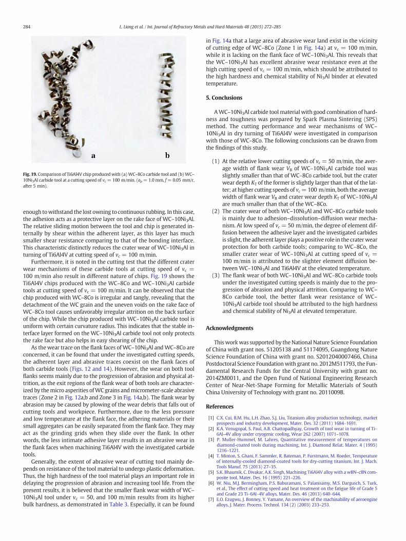
Fig. 19. Comparison of Ti6Al4V chip producedwith (a)WC–8Co carbide tool and (b)WC–10Ni3Al carbide tool at a cutting speed of vc = 100 m/min. (ap =1.0 mm, f=0.05 mm/r,after 5 min).
284 L. Liang et al. / Int. Journal of Refractory Metals and Hard Materials 48 (2015) 272–285
enough towithstand the lost owning to continuous rubbing. In this case,the adhesion acts as a protective layer on the rake face of WC–10Ni3Al.The relative sliding motion between the tool and chip is generated in-ternally by shear within the adherent layer, as this layer has muchsmaller shear resistance comparing to that of the bonding interface.This characteristic distinctly reduces the crater wear of WC–10Ni3Al inturning of Ti6Al4V at cutting speed of vc = 100 m/min.
Furthermore, it is noted in the cutting test that the different craterwear mechanisms of these carbide tools at cutting speed of vc =100 m/min also result in different nature of chips. Fig. 19 shows theTi6Al4V chips produced with the WC–8Co and WC–10Ni3Al carbidetools at cutting speed of vc = 100 m/min. It can be observed that thechip produced with WC–8Co is irregular and tangly, revealing that thedetachment of the WC grain and the uneven voids on the rake face ofWC–8Co tool causes unfavorably irregular attrition on the back surfaceof the chip. While the chip produced with WC–10Ni3Al carbide tool isuniform with certain curvature radius. This indicates that the stable in-terface layer formed on the WC–10Ni3Al carbide tool not only protectsthe rake face but also helps in easy shearing of the chip.
As thewear trace on the flank faces ofWC–10Ni3Al andWC–8Co areconcerned, it can be found that under the investigated cutting speeds,the adherent layer and abrasive traces coexist on the flank faces ofboth carbide tools (Figs. 12 and 14). However, the wear on both toolflanks seems mainly due to the progression of abrasion and physical at-trition, as the exit regions of the flank wear of both tools are character-ized by themicro asperities ofWCgrains andmicrometer-scale abrasivetraces (Zone 2 in Fig. 12a,b and Zone 3 in Fig. 14a,b). The flank wear byabrasion may be caused by plowing of the wear debris that falls out ofcutting tools and workpiece. Furthermore, due to the less pressureand low temperature at the flank face, the adhering materials or theirsmall aggregates can be easily separated from the flank face. They mayact as the grinding grids when they slide over the flank. In otherwords, the less intimate adhesive layer results in an abrasive wear inthe flank faces when machining Ti6Al4V with the investigated carbidetools.
Generally, the extent of abrasive wear of cutting tool mainly de-pends on resistance of the tool material to undergo plastic deformation.Thus, the high hardness of the tool material plays an important role indelaying the progression of abrasion and increasing tool life. From thepresent results, it is believed that the smaller flank wear width of WC–10Ni3Al tool under vc = 50, and 100 m/min results from its higherbulk hardness, as demonstrated in Table 3. Especially, it can be found
in Fig. 14a that a large area of abrasive wear land exist in the vicinityof cutting edge of WC–8Co (Zone 1 in Fig. 14a) at vc = 100 m/min,while it is lacking on the flank face of WC–10Ni3Al. This reveals thatthe WC–10Ni3Al has excellent abrasive wear resistance even at thehigh cutting speed of vc = 100 m/min, which should be attributed tothe high hardness and chemical stability of Ni3Al binder at elevatedtemperature.
5. Conclusions
AWC–10Ni3Al carbide tool materialwith good combination of hard-ness and toughness was prepared by Spark Plasma Sintering (SPS)method. The cutting performance and wear mechanisms of WC–10Ni3Al in dry turning of Ti6Al4V were investigated in comparisonwith those of WC–8Co. The following conclusions can be drawn fromthe findings of this study.
(1) At the relative lower cutting speeds of vc = 50 m/min, the aver-age width of flank wear VB of WC–10Ni3Al carbide tool wasslightly smaller than that of WC–8Co carbide tool, but the craterwear depth KT of the former is slightly larger than that of the lat-ter; at higher cutting speeds of vc=100 m/min, both the averagewidth of flank wear VB and crater wear depth KT of WC–10Ni3Alare much smaller than that of the WC–8Co.
(2) The crater wear of both WC–10Ni3Al and WC–8Co carbide toolsis mainly due to adhesion–dissolution–diffusion wear mecha-nism. At low speed of vc =50 m/min, the degree of element dif-fusion between the adhesive layer and the investigated carbidesis slight, the adherent layer plays a positive role in the craterwearprotection for both carbide tools; comparing to WC–8Co, thesmaller crater wear of WC–10Ni3Al at cutting speed of vc =100 m/min is attributed to the slighter element diffusion be-tween WC–10Ni3Al and Ti6Al4V at the elevated temperature.
(3) The flank wear of both WC–10Ni3Al and WC–8Co carbide toolsunder the investigated cutting speeds is mainly due to the pro-gression of abrasion and physical attrition. Comparing to WC–8Co carbide tool, the better flank wear resistance of WC–10Ni3Al carbide tool should be attributed to the high hardnessand chemical stability of Ni3Al at elevated temperature.
Acknowledgments
This workwas supported by theNational Nature Science Foundationof China with grant nos. 51205138 and 51174095, Guangdong NatureScience Foundation of China with grant no. S2012040007466, ChinaPostdoctoral Science Foundationwith grant no. 2012M511793, the Fun-damental Research Funds for the Central University with grant no.2014ZM0011, and the Open Fund of National Engineering ResearchCenter of Near-Net-Shape Forming for Metallic Materials of SouthChina University of Technology with grant no. 2011009B.
References
[1] C.X. Cui, B.M. Hu, L.H. Zhao, S.J. Liu, Titanium alloy production technology, marketprospects and industry development, Mater. Des. 32 (2011) 1684–1691.
[2] K.A. Venugopal, S. Paul, A.B. Chattopadhyay, Growth of tool wear in turning of Ti–6Al–4V alloy under cryogenic cooling, Wear 262 (2007) 1071–1078.
[3] P. Muller-Hummel, M. Lahres, Quantitative measurement of temperatures ondiamond-coated tools during machining, Int. J. Diamond Relat. Mater. 4 (1995)1216–1221.
[4] T. Minton, S. Ghani, F. Sammler, R. Bateman, P. Furstmann, M. Roeder, Temperatureof internally-cooled diamond-coated tools for dry-cutting titanium, Int. J. Mach.Tools Manuf. 75 (2013) 27–35.
[5] S.K. Bhaumik, C. Divakar, A.K. Singh, Machining Ti6Al4V alloy with a wBN–cBN com-posite tool, Mater. Des. 16 (1995) 221–226.
[6] W. Niu, M.J. Bermingham, P.S. Baburamani, S. Palanisamy, M.S. Dargusch, S. Turk,et al., The effect of cutting speed and heat treatment on the fatigue life of Grade 5and Grade 23 Ti–6Al–4V alloys, Mater. Des. 46 (2013) 640–644.
[7] E.O. Ezugwu, J. Bonney, Y. Yamane, An overview of the machinability of aeroenginealloys, J. Mater. Process. Technol. 134 (2) (2003) 233–253.
285L. Liang et al. / Int. Journal of Refractory Metals and Hard Materials 48 (2015) 272–285
[8] J.X. Deng, Y.S. Li, W.L. Song, Diffusion wear in dry cutting of Ti–6Al–4V with WC/Cocarbide tools, Wear 265 (2008) 1776–1783.
[9] D.H. Zheng, X.Q. Li, X. Ai, C. Yang, Y.Y. Li, Bulk WC–Al2O3 composites prepared byspark plasma sintering, Int. J. Refract. Met. Hard Mater. 30 (2012) 51–56.
[10] H.C. Kim, I.J. Shon, J.E. Garay, Z.A. Munir, Consolidation and properties of binderlesssub-micron tungsten carbide by field-activated sintering, Int. J. Refract. Met. HardMater. 22 (2004) 257–264.
[11] B. Huang, L.D. Chen, S.Q. Bai, Bulk ultrafine binderlessWC prepared by spark plasmasintering, Scr. Mater. 54 (2006) 441–445.
[12] M. Johnson, D.E. Mikkola, P.A. March, R.N. Wright, The resistance of nickel and ironaluminides to cavitation erosion and abrasive wear, Wear 140 (2) (1990) 279–289.
[13] X.J. Wan, J.H. Zhu, C.T. Liu, Hydrogen diffusivity in boron-doped polycrystallineNi3Al, Scr. Metall. Mater. 31 (1994) 677–681.
[14] C.T. Liu, D.P. Pope, Ni3Al and its Alloys, Wiley, New York, 2000.[15] S. Buchholz, Z.N. Farhat, G.J. Kipouros, K.P. Plucknett, The reciprocating wear behav-
iour of Ti-Ni3Al cermets, Int. J. Refract. Met. Hard Mater. 33 (2012) 44–52.[16] A.V. Tumanov, Y.V. Gostev, V.S. Panov, Y.F. Kots, Wetting of TiC–WC system carbides
with molten Ni3Al, Sov. Powder Metall. Met. Ceram. 25 (1986) 428–430.[17] C.T. Liu, Intergranular fracture and boron effects in Ni3Al and other intermetallics-
introductory paper, Scr. Metall. Mater. 25 (1991) 1231–1236.[18] C.L. Yeh, W.Y. Sung, Combustion synthesis of Ni3Al by SHS with boron additions, J.
Alloys Compd. 390 (2005) 74–81.[19] M. Ahmadian, D.Wexlar, Liquid phase sintering ofWC–FeAl andWC–Ni3Al compos-
ites with and without boron, Mater. Sci. Forum 32 (3) (2003) 1951–1956.[20] M. Ahmadian, D. Wexlar, Abrasive wear of WC–FeAl–B and WC–Ni3Al–B compos-
ites, Int. J. Refract. Met. Hard Mater. 23 (2005) 155–159.[21] T.N. Tiegs, K.B. Alexander, K.P. Plucknett, P.A. Menchhofer, P.F. Becher, S.B. Waters,
Ceramic composites with a ductile Ni3Al binder phase, Mater. Sci. Eng. A 209(1996) 243–247.
[22] X.Q. Li, J. Chen, D.H. Zheng, S.G. Qu, Z.Y. Xiao, Preparation andmechanical propertiesof WC–10Ni3Al cemented carbides with plate-like triangular prismatic WC grains, J.Alloys Compd. 544 (2012) 134–140.
[23] Z.Y. Xiao, The Preparation and Properties of WC–10Ni3Al Cemented Carbides withPlate-like WC Grains, (Master Dissertation) South China University of Technology,2011.
[24] G.R. Anstis, P. Chantikul, B.R. Lawn, D.B. Marshall, A critical evaluation of indentationtechniques for measuring fracture toughness: I, direct crack measurement, J. Am.Ceram. Soc. 64 (9) (1981) 533–538.
[25] Z.X. Guo, J. Xiong, M. Yang, X.Y. Song, C.J. Jiang, Effect of Mo2C on themicrostructureand properties of WC–TiC–Ni cemented carbide, Int. J. Refract. Met. Hard Mater. 26(2008) 601–605.
[26] J.A. Hawk, D.E. Alman, Abrasive wear of intermetallic-based alloys and composites,Mater. Sci. Eng. A 239 (1997) 899-06.
[27] http://en.wikipedia.org/wiki/Cobalt.[28] J.P. Davim, L. Figueira, Machinability evaluation in hard turning of cold steel (D2)
with ceramic tools using statistical techniques, Mater. Des. 28 (2007) 1186–1191.[29] P.A. Dearnley, A.N. Grearson, Evaluation of principal wear mechanisms of cemented
carbides and ceramics used for a machining titanium alloy IMI 318, Mater. Sci.Technol. 2 (1) (1986) 47–58.
[30] X. Yang, R.C. Liu, Machining titanium and its alloys, Mater. Sci. Technol. 3 (1) (1999)107–139.
[31] L.V. Colwell, W.C. Truckenmiller, Cutting characteristics of titanium and its alloys,Mech. Eng. 76 (480) (1954) 461–466.
[32] M.Wang, Y.Z. Zhang, Diffusion wear inmilling titanium alloys, Mater. Sci. Technol. 4(1984) 548–553.
[33] P.D. Hartung, B.M. Kramer, Tool Wear in Titanium Machining, Ann. CIRP 32 (1)(1982) 75–80.
[34] R.A. Perez, H. Nakajima, F. Dyment, Diffusion in α-Ti and Zr, Mater. Trans. 44 (1)(2003) 2–13.
[35] Y. Minamino, S.B. Jung, T. Yamane, K. Hirao, Diffusion of cobalt, chromium, and tita-nium in Ni3Al, Metall. Trans. A; 23 (10) (1992) 2783–2790.
[36] P.G. Shewmon, Diffusion in Solids, McGraw-Hill, New York, 1963..