wearable torso exoskeletons for human load carriage and
TRANSCRIPT

Wearable Torso Exoskeletons for
Human Load Carriage and Correction of Spinal Deformities
Joon-Hyuk Park
Submitted in partial fulfillment of the
requirements for the degree of
Doctor of Philosophy
in the Graduate School of Arts and Sciences
COLUMBIA UNIVERSITY
2016

© 2016
Joon-Hyuk Park
All rights reserved

ABSTRACT
Wearable Torso Exoskeletons for Human Load Carriage and Correction of Spinal Deformities
Joon-Hyuk Park
The human spine is an integral part of the human body. Its functions include mobilizing the torso,
controlling postural stability, and transferring loads from upper body to lower body, all of which
are essential for the activities of daily living. However, the many complex tasks of the spine
leave it vulnerable to damage from a variety of sources. Prolonged walking with a heavy
backpack can cause spinal injuries. Spinal diseases, such as scoliosis, can make the spine
abnormally deform. Neurological disorders, such as cerebral palsy, can lead to a loss of torso
control. External torso support has been used in these cases to mitigate the risk of spinal injuries,
to halt the progression of spinal deformities, and to support the torso. However, current torso
support designs are limited by rigid, passive, and non-sensorized structures. These limitations
were the motivations for this work in developing the science for design of torso exoskeletons that
can improve the effectiveness of current external torso support solutions. Central features to the
design of these exoskeletons were the abilities to sense and actively control the motion of or the
forces applied to the torso. Two applications of external torso support are the main focus in this
study, backpack load carriage and correction of spine deformities. The goal was to develop torso
exoskeletons for these two applications, evaluate their effectiveness, and exploit novel assistive
and/or treatment paradigms.
With regard to backpack load carriage, current torso support solutions are limited and do
not provide any means to measure and/or adjust the load distribution between the shoulders and
the pelvis, or to reduce dynamic loads induced by walking. Because of these limitations,

determining the effects of modulating these loads between the shoulders and the pelvis has not
been possible. Hence, the first scientific question that this work aims to address is What are the
biomechanical and physiological effects of distributing the load and reducing the dynamic load
of a backpack on human body during backpack load carriage?
Concerning the correction of spinal deformities, the most common treatment is the use of
a spine brace. This method has been shown to effectively slow down the progression of spinal
deformity. However, a limitation in the effectiveness of this treatment is the lack of knowledge
of the stiffness characteristics of the human torso. Previously, there has been no means to
measure the stiffness of human torso. An improved understanding of this subject would directly
affect treatment outcomes by better informing the appropriate external forces (or displacements)
to apply in order to achieve the desired correction of the spine. Hence, the second scientific
question that this work aims to address is How can we characterize three dimensional stiffness of
the human torso for quantifiable assessment and targeted treatment of spinal deformities?
In this work, a torso exoskeleton called the Wearable upper Body Suit (WEBS) was
developed to address the first question. The WEBS distributes the backpack load between the
shoulders and the pelvis, senses the vertical motion of the pelvis, and provides gait synchronized
compensatory forces to reduce dynamic loads of a backpack during walking. It was hypothesized
that during typical backpack load carriage, load distribution and dynamic load compensation
reduce gait and postural adaptations, the user’s overall effort and metabolic cost. This hypothesis
was supported by biomechanical and physiological measurements taken from twelve healthy
male subjects while they walked on a treadmill with a 25 percent body weight backpack. In
terms of load distribution and dynamic load compensation, the results showed reductions in gait
and postural adaptations, muscle activity, vertical and braking ground reaction forces, and

metabolic cost. Based on these results, it was concluded that the wearable upper body suit can
potentially reduce the risk of musculoskeletal injuries and muscle fatigue associated with
carrying heavy backpack loads, as well as reducing the metabolic cost of loaded walking.
To address the second question, the Robotic Spine Exoskeleton (ROSE) was developed.
The ROSE consists of two parallel robot platforms connected in series that can adjust to fit
snugly at different levels of the human torso and dynamically modulate either the posture of the
torso or the forces exerted on the torso. An experimental evaluation of the ROSE was performed
with ten healthy male subjects that validated its efficacy in controlling three dimensional
corrective forces exerted on the torso while providing flexibility for a wide range of torso
motions. The feasibility of characterizing the three dimensional stiffness of the human torso was
also validated using the ROSE. Based on these results, it was concluded that the ROSE may
alleviate some of the limitations in current brace technology and treatment methods for spine
deformities, and offer a means to explore new treatment approaches to potentially improve the
therapeutic outcomes of the brace treatment.

i
Table of Contents
List of Figures .....................................................................................................iv
List of Tables .......................................................................................................ix
Acknowledgments .................................................................................................x
Chapter 1 Introduction .................................................................................... 1
1.1 Backpack load carriage: issues and solutions ............................................................... 3
1.1.1 Issues related to backpack load carriage ........................................................... 4
1.1.2 Strategies to assist backpack load carriage and their limitations ...................... 6
1.1.3 Needs for a torso exoskeleton for human load carriage .................................... 8
1.2 Spinal deformities: cause and treatment ..................................................................... 10
1.2.1 Scoliosis, a spinal deformity............................................................................ 10
1.2.2 Bracing treatment and its limitation ................................................................ 11
1.2.3 Needs for a torso exoskeleton for correction of spinal deformity ................... 15
1.3 Overview of chapters .................................................................................................. 16
Chapter 2 Wearable upper Body Suit (WEBS) for backpack load carriage.. 18
2.1 Introduction ................................................................................................................. 18
2.2 Design ......................................................................................................................... 19
2.3 Gait-synchronized force control for dynamic load compensation .............................. 24
2.3.1 Desired assistive force computation................................................................ 24
2.3.2 Desired assistive force implementation........................................................... 25
2.4 Controller evaluation................................................................................................... 26
2.5 Conclusion .................................................................................................................. 30
Chapter 3 Human load carriage study using WEBS...................................... 31
3.1 Introduction ................................................................................................................. 31
3.2 Protocol ....................................................................................................................... 32

ii
3.3 Data Processing........................................................................................................... 35
3.4 Results ......................................................................................................................... 38
3.4.1 Kinematics....................................................................................................... 38
3.4.2 Spatiotemporal parameters .............................................................................. 41
3.4.3 Ground reaction forces .................................................................................... 42
3.4.4 Muscle activity and fatigue ............................................................................. 45
3.4.5 Metabolic cost ................................................................................................. 48
3.5 Discussion ................................................................................................................... 49
3.5.1 Reduced vertical excursion of backpack load ................................................. 49
3.5.2 Changes in gait and postural adaptations ........................................................ 49
3.5.3 Metabolic benefits ........................................................................................... 53
3.5.4 Reduced risk factors for injury ........................................................................ 55
3.6 Conclusion .................................................................................................................. 56
Chapter 4 Robotic Spine Exoskeleton (ROSE) for correction of spine
deformities ..................................................................................................... 57
4.1 Introduction ................................................................................................................. 57
4.2 Design ......................................................................................................................... 57
4.3 Control ........................................................................................................................ 60
4.4 Controller Evaluation .................................................................................................. 62
4.5 Conclusion .................................................................................................................. 65
Chapter 5 Experiment of ROSE with human subjects .................................. 67
5.1 Introduction ................................................................................................................. 67
5.2 Protocol ....................................................................................................................... 68
5.3 Results ......................................................................................................................... 72
5.3.1 Feasible range of motion with the brace ......................................................... 72
5.3.2 Constant force control during motion ............................................................. 73
5.3.3 3-point-pressure validation.............................................................................. 75
5.3.4 Stiffness characterization ................................................................................ 76

iii
5.3.5 Sensitivity and Robustness of Stiffness Measurement.................................... 85
5.4 Discussion ................................................................................................................... 89
5.5 Conclusion .................................................................................................................. 94
Chapter 6 Conclusion..................................................................................... 96
6.1 Contributions of the current work ............................................................................... 96
6.1.1 Development of a Wearable upper Body Suit................................................. 96
6.1.2 Effects of load distribution and dynamic load compensation of a backpack .. 97
6.1.3 Development of a Robotic Spine Exoskeleton................................................ 98
6.1.4 Characterizing the stiffness of human torso .................................................... 99
6.2 Suggestions for the future work .................................................................................. 99
6.2.1 WEBS and backpack load carriage study ....................................................... 99
6.2.2 Robotic Spine Exoskeleton ........................................................................... 102
Bibliography ................................................................................................ 104
Appendix ...................................................................................................... 113
Appendix A. The Second Spine ............................................................................................ 113
Appendix B. Motorized Second Spine.................................................................................. 118
Appendix C. Hardware specifications .................................................................................. 125
Appendix C. 1 Hardware configurations of the Wearable upper Body Suit ........... 125
Appendix C. 2 Hardware configurations of ROSE.................................................. 128
Appendix D. Parameterization, kinematics, and trajectory planning of the ROSE ............. 129
Appendix E. In vitro spine stiffness measurement and its implication................................. 135

iv
List of Figures
Figure 1.1 (top) Human load carriages using a backpack, (bottom) other human load carriages without
using a backpack ................................................................................................................................4
Figure 1.2 (a) BLEEX from Berkeley Bionics, (b) ExoHikers from Berkeley Bionics, (c) HULC from
Lockheed Martin, (d) double-pack, (e) backpack frame with a hip belt, (f) Exospine from Emerald Touch,
and (g) Lightning Pack........................................................................................................................8
Figure 1.3 Treatment options based on the Cobb angle ........................................................................ 11
Figure 1.4 (top) Various types of scoliosis brace: (a) Milwaukee [65], (b) Charleston [64], (c) Boston [62],
(d) Cheneau [63], and (bottom) (e) Dynamic Derotational Brace (DDB) [74, 75], (f) Dynamic Spinal
Brace (DSB) [76], (g) A Hybrid Neuroprosthesis for walking with SCI [77], and (h) ExMS-1 from
ExoDynamics [78] ............................................................................................................................ 13
Figure 2.1 Design concept of the WEBS and the lifting mechanism ..................................................... 20
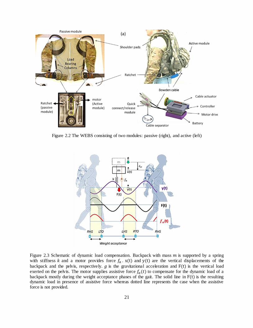
Figure 2.2 The WEBS consisting of two modules: passive (right), and active (left) ............................... 21
Figure 2.3 Schematic of dynamic load compensation. Backpack with mass is supported by a spring
with stiffness and a motor provides force . and are the vertical displacements of the
backpack and the pelvis, respectively. is the gravitational acceleration and is the vertical load
exerted on the pelvis. The motor supplies assistive force to compensate for the dynamic load of a
backpack mostly during the weight acceptance phases of the gait. The solid line in is the resulting
dynamic load in presence of assistive force whereas dotted line represents the case when the assistive
force is not provided. ........................................................................................................................ 21
Figure 2.4 The force controller implemented for gait-synchronized dynamic load compensation ............ 25

v
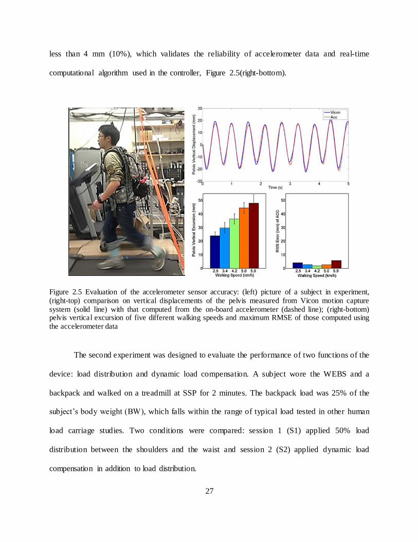
Figure 2.5 Evaluation of the accelerometer sensor accuracy: (left) picture of a subject in experiment,
(right-top) comparison on vertical displacements of the pelvis measured from Vicon motion capture
system (solid line) with that computed from the on-board accelerometer (dashed line); (right-bottom)
pelvis vertical excursion of five different walking speeds and maximum RMSE of those computed using
the accelerometer data....................................................................................................................... 27
Figure 2.6 Experimental data from S1 during which only the passive module was engaged to transfer 50%
of the backpack load from the shoulders to the pelvis: (top) pelvis vertical motion (mm) and (bottom)
force transferred from the shoulders to the pelvis measured from the cable; fs(R) and fs(L) are the
transferred force from the right and the left side of the device, respectively, and F(total) is the sum of
those forces. These forces are normalized to the backpack load............................................................ 28
Figure 2.7 Force transmission from the shoulders to the pelvis in S1 (left) compared with S2 (right)
averaged over a gait cycle; (R) and (L) denote the transferred force measured from the right and the
left side of the passive module; denotes the assistive force provided from the active module; F denotes
the total force (sum of the forces from passive and active modules); the assistive forces reduced the peaks
of the total transferred force (F) in S2 compare to S1 .......................................................................... 28
Figure 3.1(a) Experiment protocol used in the study, (b) experiment setup, and (c) body coordinate frames
based on the marker locations in zero-configuration (upright standing posture), and the global coordinate
frame origin at {O}. .......................................................................................................................... 32
Figure 3.2 (from top row) Hip, knee, and ankle sagittal plane joint angles during different trials for a
representative subject (left), and the stance-phase peak joint flexion/extension angles (dorsi-/plantar-
flexion for ankle) for the group (right); The average backpack and pelvis vertical excursion, and sagittal
plane torso flexion over the gait cycle for different trials for a representative subject (left), and the group
average of mean and range of vertical motion of the backpack and pelvis, and the mean torso flexion

vi
(right). The asterisk indicate statistically significant effect between the corresponding sessions (p <0.05)
........................................................................................................................................................ 40
Figure 4.1. (a) 3D CAD model of the ROSE, (b) physical model of the ROSE, and (c) actuated limb
design .............................................................................................................................................. 58
Figure 4.2 The design process of the robotic spine brace; Step 1: 3D scan of the body, Step 2:
superimpose the spine 3D CAD to the 3D scan of the body, Step 3: design the rings of the ROSE, Step 4:
determine the location of the rings and actuators and optimizing the workspace, Step 5: fabrication and
calibration ........................................................................................................................................ 59
Figure 4.3 Position controller implemented in the joint space; IK and FK represent inverse kinematics and
forward kinematics, respectively, and J represents Jacobian ................................................................ 61
Figure 4.4 Force controller implemented in the joint space; FK and J represent forward kinematics and
Jacobian, respectively. ...................................................................................................................... 62
Figure 4.5 Graphical representation of the command (dashed) and Vicon (solid) results from the 3-point
motion test. Rotations and translations about x, y, and z are represented by black, red and blue
respectively; (top row) the lower parallel-module and (bottom row) the upper parallel module .............. 63
Figure 4.6 Test-bed for force controller evaluation .............................................................................. 65
Figure 4.7 (right) Graphical representation of the command force (dashed-black) and measured force
(solid-blue) from ATI F/T sensor; (a) One dimensional force, and (b) three dimensional force............... 65
Figure 5.1. (a) Human subject experiment protocol and (b) torso coordinate frame used in this study ..... 68
Figure 5.2 Session 1: the range of motion test with and without the ROSE ........................................... 69
vii
Figure 5.3 3-point-pressure method evaluated using the ROSE; planar displacements were applied with
varying magnitude and directions, and forces were measured .............................................................. 70
Figure 5.4 Feasible range of motion while wearing the brace compared to subjects’ natural range of torso
motion; (left) mean and standard deviation between the two conditions, and (right) average in-brace range
of motion expressed as a percentage of no-brace range of motion ........................................................ 72
Figure 5.5 Comparison on forces exerted on the body during in-brace motions between transparent mode
and constant force control mode of a representative subject ................................................................. 74
Figure 5.6 Group mean and standard deviation of the forces during six different in-brace motions between
transparent mode and constant force mode ......................................................................................... 74
Figure 5.7 3-point-pressure validation; planar displacements ( ) induced 3-dimensional forces ...... 75
Figure 5.8 (a) Force-displacement mapping of a torso at T-10 vertebrae level of a representative subject;
subscript followed by indicates the stiffness about the corresponding degree of freedom, and (b) Group
mean and standard deviation of collinear stiffnesses of human torso at T-10 vertebrae location (n=10)
........................................................................................................................................................ 77
Figure 5.9 (a) spine vertebrae modeled as an equivalent truss/beam structure [99]; (b) human torso model
as an equivalent truss/beam structure analogous to (a); and (c) A 6x6 stiffness matrix ........................... 79
Figure 5.10 Stiffness matrix derived from a single subject. .................................................................. 81
Figure 5.11 (a) Normalized stiffness matrix (n=10); (b) stiffness matrix:
( ( )) ................................................................................................. 84

viii
Figure 5.12 Five sessions with different conditions used to test the effects of two poses (sitting-BL and
supine-T1), gaps (no gap-BL, with gap-T2, gap filled using padding-T3), and different paddings applied
(form fit-BL, with 5 mm padding-T4, and with 10 mm padding-T5) on stiffness measurement .............. 86
Figure 5.13 (a) Collinear stiffness variation between sitting and supine posture; (b) Collinear stiffness
variation due to gaps and gap filling; (c) Collinear stiffness variation due to additional layer of padding
added to the brace. ............................................................................................................................ 87

ix
List of Tables
Table 3.1. Comparison on the kinematics and spatiotemporal variables between sessions (n=12) ........... 41
Table 3.2 Comparison on the ground reaction force variables between sessions (n=12) ......................... 43
Table 3.3 Comparison on the muscle activity (iEMG) and mean power frequency (MPF) between sessions
(n=12).............................................................................................................................................. 46
Table 3.4 Comparison on the cardiopulmonary variables between sessions (n=12) ................................ 48
Table 4.1 Position and orientation error of the middle and lower segment origin from seven motions
tested ............................................................................................................................................... 64
Table 5.1 Relative magnitudes of the translational stiffness terms and rotational stiffness terms measured
from human torso in this study, compared with those measured from the spine vertebrae in other studies
[97, 4] .............................................................................................................................................. 77
x
Acknowledgments
First and foremost, I would like to express my sincere gratitude to my advisor and mentor,
Professor Sunil Agrawal, for the invaluable guidance, scholarly input and consistent
encouragement I received throughout my Ph.D. research. His support and advice have helped me
overcome many hurdles and challenges during my study and made it possible to complete this
dissertation. I was extremely lucky to meet him, as he has been a great mentor both for my
academic and personal life. I will never forget his kindness, enthusiasm and encouragement.
I would like to thank my committee members Dr. Jeffery Kysar, Dr. Gerald Ateshian, Dr.
Andrew Gordon, and Dr. David Roye for reviewing my work and giving me constructive
feedback. I also want to thank them for making my defense an enjoyable experience. I am
especially grateful for Dr. David Roye, as his advice was invaluable at various phases of the
Robotic Spine Exoskeleton research.
I would like to thank all my lab members in the Robotics and Rehabilitation Laboratory
for their wonderful suggestions and help on my research, especially Dr. Damiano Zanotto, Dr.
Vineet Vashista, Paul Stegall, Xin Jin, Jiyeon Kang, Emily Boggs, Moiz Khan, Zhiyu Sheng,
Rosemarie Murray, Daisuke Tajima, Brian Bradley, Haohan Zhang, and Onur Denizhan. I am
especially grateful for Paul Stegall who has been very kind and helpful and always willing to
lend a hand whenever I approached him, and I acknowledge and appreciate him for all his time
and efforts. I also want to thank Rosemarie Murray, Riancy Li, Emily Boggs, and Moiz Khan for
being kind enough to proofread my dissertation and provide helpful comments.

xi
I would also like to thank Prachi Backrania, Kelly Grimes, Dr. Anna-Christina Bevelaqua,
and John Tunney for their advice and help in conducting experiments with scoliosis patients. I
am thankful for Dr. Charles Kim and his team for our collaboration on the Robotic Spine
Exoskeleton project over the past few years. I am also thankful for Shashank Sharma, Dr. John
Tierney, Dr. Shridhar Yarlagadda, and Dr. John Gillespie for our collaboration on the DARPA
Warrior Web project.
I gratefully acknowledge the funding sources that made my Ph.D. work possible: the
NASA/DESGC graduate fellowship (NNX10AN63H), with grants from the Defense Advanced
Research Projects Agency (W911QX-12-C-0042) and the National Science Foundation (NSF
IIS-1527087).
I want to thank the staff of the Mechanical Engineering department for their kind support.
I particularly thank Sandra Morris, Jean Cadet, and Melbourne Francis for their administrative
help with my academics, Rakhi Hossain for getting countless orders through, and Robert Stark
and Mohammed Haroun for their assistance in the fabrication of mechanical components for my
research.
Most of all, I am forever indebted to my parents Seongik Park and Heeyeon Lee, my
sister Yoonjoo Park, my parents- in- law Taekil Kim and Eunsook Yoo, and my sister- in- law
Mary Kim. Their almost unbelievable support, prayers, and love have given me strength to carry
out this task, and I dedicate my thesis to them.
Finally, words cannot express how grateful I am to my dearest wife Minhee Kim who has
been loving, supportive, encouraging, and patient and I appreciate every moment that we have
had together. None of this would have been possible without her patience and love, and I can’t
thank her enough. I also want to thank my beloved son David Sunghyun Park for just being a

xii
sweet little boy who has filled me up with happiness and laughter, and my unborn son Noah for
coming into my life as a surprise whom I can’t wait to meet.
Above all, I owe it all to my God for granting me the faith, wisdom, health, and strength
to undertake this research task and see it through to completion. He has been leading my life and
forever will be. I thank you lord for all that you have given to me. Thank you.

1
Chapter 1
Introduction
The human spine is a versatile and fascinating structure. It serves as a pillar to support the body's
weight and external load; protects the spinal cord, nerves and vertebral artery; acts as a natural
damper to absorb and distribute shock/load; allows for mobility and flexibility of torso to
perform activities of daily living; and maintains balance and postural stability of the body [1, 2, 3,
4, 5]. However, perhaps of the complex structure needed to achieve both rigidity and flexibility
for these functions, it is also vulnerable to damage, which can diminish these functions. This can
come in the form of spinal injuries, as from prolonged walking with a heavy backpack. It can
also come from spinal diseases, such as scoliosis, causing spinal deformities. Neurological
diseases, such as cerebral palsy, and spinal cord injury can cause a loss of torso control.
External torso support is needed in these cases to mitigate the risk of spinal injuries, to
curtail the progression of spinal deformities, and to support the torso. However, current torso
support solutions are limited by rigid, passive, and non-sensorized designs. The main focus of
this work is, therefore, to develop the science for design of torso exoskeletons that alleviate these
limitations in two domains, backpack load carriage and correction of spine deformities ; to
evaluate their effectiveness in these applications; and explore novel assistive and/or treatment
paradigms.
Regarding the first domain, walking with a heavy backpack increases the risk of
musculoskeletal injuries, muscle fatigue, and metabolic cost [7-20]. This is due to the static and

2
dynamic load of a backpack on human body that compresses the spine and torso from the
shoulders, and increases the lower limb joint torque necessary to compensate for the dynamic
loads of a backpack. By distributing the load between the shoulders and the pelvis, and reducing
the dynamic load of a backpack during walking, some of these issues can be attenuated.
Concerning the second domain, various musculoskeletal diseases can cause the human
spine to develop abnormal curves. A typical treatment method to correct spinal deformities is the
use of torso braces. These braces are generally constructed of a single rigid plastic shell, which
imposes several limitations on the current brace treatment method and its outcomes. By sensing
and actively controlling either the position or the forces of the brace as it corrects the spinal
curve, some of these limitations can be addressed.
This work will incorporate these two features into two different torso exoskeleton designs:
the Wearable upper Body Suit (WEBS) and the Robotic Spine Exoskeleton (ROSE), present the
experimental evaluations on the functions facilitated in each, and discuss their practical
implications and potential benefits to human load carriage and spinal deformity correction
applications.
In this chapter, issues related to backpack load carriage are reviewed, and both current
solutions and their limitations are presented. The motivation and rationale behind the work on
the torso exoskeleton design for backpack load carriage is followed. Then, scoliosis, a spine
disease causing spinal deformity, is introduced. Current bracing treatment methods and their
limitations are addressed to motivate the work on the torso exoskeleton for correction of spinal
deformities. The chapter concludes with an overview of subsequent chapters.

3
1.1 Backpack load carriage: issues and solutions
For most human beings, from school children to fire fighters to military personnel, load carriage
is part of daily life. In most cases the load is supported on the shoulders or the back, as shown in
Figure 1.1. For a long time, backpacks have been a common way of carrying load. However,
walking with a heavy backpack can lead to increased orthopedic injuries, fatigue and metabolic
cost. School children on average bear loads of up to 38% of their body weight (BW), a level of
which higher chances of muscle fatigue and lower back pain can be associated [6, 7, 8, 9].
Prevalence of lower back pain is higher for people that carry heavy loads on a regular basis, e.g.,
a USA Marine rifleman’s assault load can weigh between 57% - 79% BW, well above the
threshold for injury [10]. In 2014, more than 28,100 individuals were treated for backpack
related injuries, and more than 8,300 of those injuries were children age between 5 and 18 in the
United States [11]. Despite these well-known issues associated with backpack load carriage,
current engineering solutions are still limited to the following two strategies: distributing the load
across different areas of the torso, or using lower limb devices that either to transfer the load
directly to the ground or to provide joint torques to reduce the lower limb muscle work. In the
following sections, the effects of backpack load on human walking and related issues are
presented. Then, the limitations of the aforementioned strategies are discussed to justify the need
for a torso exoskeleton for assisting in backpack load carriage.

4
Figure 1.1 (top) Human load carriages using a backpack, (bottom) other human load carriages without using a backpack
1.1.1 Issues related to backpack load carriage
Carrying a heavy backpack can increase the risk of musculoskeletal injuries. Such injuries occur
on both the upper body (rucksack palsy, lower back pain, spasm, disc tear/herniation, spinal
stenosis) and the lower limbs (foot blisters, metatarsalgia, stress fractures, and knee pain) [12, 13,
14, 15, 16, 17, 18]. Higher metabolic costs [19, 20, 21], increased muscle activity and fatigue [15,
22, 6, 23, 24, 25, 26], changes in gait and posture [17, 18, 27, 28, 29, 30], and increased ground
reaction forces [15, 16, 17, 28, 31, 30] are typically reported with human load carriage. Injuries
on the upper body are mainly caused by accumulated stress on spine and lumbar muscles
required to support the additional loads on the shoulders and to maintain postural stability while
walking [15, 18, 21]. Lower limb injuries are mainly caused by changes in gait kinematics to
compensate for the vertical accelerations of the backpack and the resulting dynamic loads [12, 14,
16, 17]. Human walking can be modeled as an inverted pendulum that induces vertical motions
of the pelvis and upper body [32, 33]. Over-ground walking generates vertical accelerations of

5
the head, thorax and pelvis, with peak accelerations about [34]. These accelerations are
periodic functions with roughly twice the frequency of the human gait. The backpack, which is
tightly attached to the upper body, undergoes similar vertical motions. Therefore, the periodic
vertical accelerations of the backpack exert dynamic loads on the body, in addition to a static
load, which is about 20% of the static load for over-ground walking [34].
These static and dynamic loads alter normal gait and posture, and require greater lower
limb muscle effort as the human body needs to compensate for the additional forces exerted on it.
These effects are most significant during the weight acceptance and the push-off phases of the
gait when the body is required to decelerate and accelerate the backpack load. Previous studies
have reported the following body adaptations in kinematics and muscle kinetics as a result of a
backpack load: higher stance-phase peak knee flexion, reduced swing phase, longer double
support phase, increased ankle dorsi/plantar flexion and higher muscle activity in the lower
extremities during the weight acceptance and push-off phases [13, 15, 17, 22, 29, 35]. These gait
adaptations combined with the increase in lower limb muscle activity reflect the body’s attempt
to dampen the increased impact forces, due to added mass, at initial contact (heel strike) and to
acquire more time to transfer the load between the legs during weight acceptance. Consequently,
metabolic rate, muscle fatigue, and ground reaction forces increase with the load. Walking with a
backpack has also been found to increase the forward lean of the trunk to maintain the combined
center of mass (COM) of the upper body and carried load over the support polygon made by the
feet. While such adaptations are necessary to achieve postural stability during loaded walking, it
has been hypothesized that it causes foot strain, injury of the legs, and back injur ies [12, 13, 14].
The dynamics of the backpack in human load carriage has been studied. Ren et al. [36]
investigated the load carriage dynamics using a test-rig that simulates different backpack

6
suspension characteristics in human walking. They reported that by decreasing the suspension
stiffness, it is possible to lower the peak vertical force exerting on the torso. This can also
potentially decrease the lower limb joint loads. Foissac et al. [37] reported reduction in oxygen
consumption when the vertical excursion of the backpack is reduced. Lower vertical excursion of
the backpack has implications in reduced pressure on the shoulders at the shoulder straps and
reduced forces transferred to the waist belt and the lower limbs. Similar results were also shown
where the energy expenditure in human load carriage is strongly influenced by the vertical forces
exerted [38] and the vertical motion of the body’s center of mass [39, 40].
1.1.2 Strategies to assist backpack load carriage and their limitations
The first strategy to alleviate the issues of backpack load carriage is distributing the load across
different areas of the torso, such as between the anterior and posterior of the torso or between the
shoulders and the waist. It has been shown that locating the load mass close to the body’s COM,
e.g., by means of double-packs, Figure 1.2(d), results in lower metabolic cost [41] and lower
postural deviations from natural walking [17, 42, 43]. This brings the load closer to the normal
human COM and allows for a more natural posture without requiring additional stabilizing
muscle activation. However, double-packs hinder arm and trunk movements more than
backpacks, restrict the field of vision, and even induce ventilatory impairments and heat stress
symptoms [35, 44]. Due to these issues, double-packs are not widely used.
Backpacks featuring a frame and a hip belt, Figure 1.2(e), are currently the most viable
solution. They have been shown to alleviate stress on the shoulders and decrease lower back pain
by partially transferring the load to the hips [12, 14, 21], even though the effectiveness depends
on the specific backpack model. Decreased pressures on the shoulders may not only reduce

7
shoulder discomfort and the nerve compressions that cause rucksack palsy [14], but also reduce
the stress on the spine since the rigid structure of the backpack acts as an alternative pathway for
transferring loads to the lower body. Moreover, there is less work required for the trunk muscles
to stabilize the posture as the net load carried on the shoulders is reduced by partially transferring
it to the waist. External load bearing devices that have a similar function of distributing the
backpack load between the shoulders and the waist have also been developed. For example,
Exospine from Emerald Touch, Figure 1.2(f), was designed for situations where significant loads
have to be carried outside the backpack (e.g., a military tactical vest weighs up to 13.6kg, nearly
18 % BW [10]) or for carrying loads directly over the shoulders (e.g., moving boxes or
construction materials, or other person) [45, 46]. However, none of these backpack load
distribution designs incorporates a mechanical design to measure or adjust the load distribution.
The second strategy to alleviate issues of backpack load carriage is to use lower limb
exoskeletons, Figure 1.2(a)-(c), e.g., BLEEX from Berkeley Bionics [47]. These designs utilize a
rigid leg exoskeleton attached directly to a backpack frame such that the load bypasses the
human body and is transferred directly to the ground. This method may effectively reduce the net
load carried by the body, but it requires adding rigid structures and joints on the lower limbs
which may add bulk and weight to the lower limbs.

8
Figure 1.2 (a) BLEEX from Berkeley Bionics, (b) ExoHikers from Berkeley Bionics, (c) HULC from Lockheed Martin, (d) double-pack, (e) backpack frame with a hip belt, (f) Exospine from Emerald Touch, and (g) Lightning Pack
Another approach that attempts to reduce the dynamic loads of a backpack is to impose
differential motions between the backpack and the body by designing a “suspended- load”
backpack in which the load is suspended by an elastic cord on the backpack frame. It has been
shown to passively reduce the accelerative force of a backpack and lower the associated
metabolic cost, Figure 1.2(g), [38]. However, this concept can only be realized through a
customized backpack design hence its applicability for general backpack load carriage or other
load carriages without using a backpack is limited.
1.1.3 Needs for a torso exoskeleton for human load carriage
These previous studies and efforts in backpack load assistive strategies point out several features
that have been targeted to alleviate issues in backpack load carriage. One of the features is the
distribution of the backpack load between the shoulders and the waist - this may help relieve

9
stress on the shoulders and lower back. Another feature is dynamic load compensation of a
backpack - this may decrease the lower limb joint loads and muscle efforts. Nevertheless, these
features are not yet fully incorporated in any of the current load assistive devices. They are
particularly lack sensing and adjusting capabilities of the load distribution between the shoulders
and the waist, and cannot actively compensate for the dynamic load based on human motion.
Consequently, there is a breach in understanding as to biomechanical and physiological effects of
load distribution and dynamic load compensation of a backpack on human body.
Therefore, the first aim of this work is to develop a torso exoskeleton that facilitates load
distribution and dynamic load compensation features, and to provide experimental evaluation of
the effects of these features on the human body. For this aim, three different designs of torso
exoskeletons (Second Spine, Motorized Second Spine, and Wearable upper Body Suit) were
prototyped to reduce the body’s compensations and the user’s effort in backpack load carriage
with the following aims: (i) distribution of the external load between the shoulders and the
pelvis to reduce postural adaptation while relieving stress on the shoulders and the lower back,
and (ii) compensation of the dynamic loads of a backpack by providing external assistive forces
to reduce lower limb muscle use. Furthermore, real-time measurement and control of the
backpack load exerted on the body were targeted features by which the assistive forces could be
regulated for various gait and backpack load conditions. Each version has varying designs but
they share the same basic functionality, i.e., measuring and adjusting the load distribution
between the shoulders and the waist.
The first design was named “Second Spine” because it adds an alternative load pathway
in addition to the human spine which can passively adjust the load transferred from the shoulders
to the waist. The second design, Motorized Second Spine, has the same feature of the Second

10
Spine but with added functionality of dynamic load compensation through incorporating motors,
sensors and real-time controllers. The third design, Wearable upper Body Suit (WEBS),
improved the portability and wearability of the Motorized Second Spine, presented in detail in
Chapter 2. A human subject study was conducted to evaluate the effects of load distribution and
dynamic load compensation on backpack load carriage using the wearable upper body suit,
presented in Chapter 3.
1.2 Spinal deformities: cause and treatment
1.2.1 Scoliosis, a spinal deformity
Spinal deformity occurs when there is unnatural curvature of the spine, as in scoliosis or
kyphosis and Scheuermann's disease [48]. It also occurs due to defect (e.g. spondylolisthesis) or
damage to the spine [48]. Scoliosis is one of the most common spinal deformities characterized
by side-to-side abnormal curvatures of the spine [49]. In the United States, 1-3% of adolescents
suffer from idiopathic scoliosis each year [50], and 30,000 children are prescribed braces to treat
scoliosis while 38,000 patients undergo spinal fusion surgery [49]. On an x-ray taken from the
back, the spine of a person with scoliosis looks more like a “C” or a “S” curve than a straight line.
Cobb angle, which refers to the measurement of coronal plane deformity on anteroposterior
plane radiographs [51], of 10 degrees or more are diagnosed as scoliosis [52, 50].
This disorder usually appears during adolescent years of growth and progresses until
skeletal maturity. More than 80 % of scoliosis is idiopathic, meaning “of undetermined cause”
[53]. The remaining 20% of scoliosis is due to congenital spinal column abnormalities,
neurologic disorders, genetic conditions, and others [54]. Girls and boys are equally affected by

11
less severe degrees of scoliosis. Girls however are eight times more likely than boys to develop
progressive curves [55, 56]. Such abnormal curves can make the individual’s shoulders or waist
appear uneven, Figure 1.3. The bones may also be rotated, making one shoulder blade more
prominent than the other. It also impacts the quality of life of those affected by limiting their
activity, causing pain, reducing respiratory function, and diminishing self-esteem [49]. Severe
scoliosis (Cobb angle > 40~45°) can be associated with diminished digestive, hormonal,
musculoskeletal and neurological function of the body; spinal fusion is recommended in these
severe cases [50, 57], Figure 1.3.
Figure 1.3 Treatment options based on the Cobb angle
1.2.2 Bracing treatment and its limitation
The predominant non-invasive treatment for scoliosis is bracing. A scoliosis brace is typically a
rigid plastic shell that fits around the trunk and hips and applies counter-pressure on the
abnormal curves of the spine. A typical TLSO (thoraco- lumbo-sacral orthosis) brace is
recommended to be worn for up to 18 to 23 hours a day to restore spine alignment. The principle

12
behind clinical treatment with the brace is that external pressure and support on the curve
stimulates more normal growth of the spine inside the body over time [58, 59, 60], which curtails
curve progression and thereby mitigates the need for surgery. While bracing has long been a
widely accepted practice in treating scoliosis, systematic and randomized group studies on the
effectiveness of spine braces have been performed only recently [61]. The results clearly showed
that braces help to reduce the progression of abnormal spine curves in adolescents. There was
also a significant positive association between hours of brace wear and rate of treatment success.
This study justifies scientifically the need for scoliosis intervention with braces.
There are several types of standard scoliosis braces each with slightly varying designs
and functions [62, 63, 64, 65], as shown in Figure 1.4(a)-(d). They are all composed of either a
single rigid body or multiple bodies rigidly connected to each other. The Milwaukee brace,
Figure 1.4(a), was first developed in 1946 [66, 65]. It applies traction on the spine through a steel
and leather pelvic base from which one anterior and two poster ior arms extend to support the
head at the occiput and throat. De-rotational forces are applied at the points of rib prominence
through pads attached to the pelvic girdle. This class is no longer used in North America because
of its abnormal effect on jaw growth [59]. The Charleston bending brace, Figure 1.4(b), was
developed in 1978 to be used primarily during night-time to address compliance issues in
patients with scoliosis for whom other treatment options had failed [64, 67, 68, 69]. The
Charleston brace operates on the principle that passive bending of the spine without traction can
promote correction of spinal deformity by inducing stretching forces on the concavity of the
curve and compression at the convexity [64]. The Boston brace, Figure 1.4(c), has gained
popularity due to its low profile, ease of application, and high patient satisfaction and compliance
[70, 71, 62]. It consists of a prefabricated plastic brace with various sizes of paddings to correct

13
deformities in lumbar, thoraco-lumbar, and thoracic regions of the spine. It applies 3-point-
pressure with rotation [62]. The Cheneau brace, Figure 1.4(d), consists of multiple molded rigid
pieces which are screwed on to a central backbone rod to maintain an overall normal curvature of
the spine. A 3-point-pressure pushes the peak of the abnormal curve inwards while holding at the
two ends [72, 73]. The general principle of correction is de-torsion and sagittal plane
normalization.
Figure 1.4 (top) Various types of scoliosis brace: (a) Milwaukee [65], (b) Charleston [64], (c) Boston [62], (d) Cheneau [63], and (bottom) (e) Dynamic Derotational Brace (DDB) [74, 75], (f) Dynamic Spinal Brace (DSB) [76], (g) A Hybrid Neuroprosthesis for walking with SCI [77], and (h) ExMS-1 from ExoDynamics [78]
Though these braces differ in their designs and principles, they all share the same goal to
correct or stop the progression of abnormal curvature of the spine. However, the underlying
brace technology used in these braces has not significantly changed over the last 50 years and
still remains archaic because of the following limitations: (i) They are rigid and typically restrict
normal activities of daily living (ADL) and are uncomfortable, which makes it difficult to wear
for extended periods of time and leads to poor user compliance; (ii) They are passive and

14
incapable of active modulation or control of corrective forces; (iii) They are static which makes
them incapable of adapting to changes in the spine over the course of treatment; (iv) They
achieve spine correction by reconfiguring the posture of the torso without knowing how much
force is being applied, which could cause undesirable deformation to the bone structure or
excessive localized forces on the skin; (v) They do not provide real-time data on the torso that
can be used for patient monitoring, data mining, or planning of the clinical treatment. To address
some of these limitations and allow for greater mobility, the SpineCor brace was recently
proposed which uses a series of elastic straps to correct the curvature [79, 80]. However, this
brace showed varying levels of success, and requires extensive training to provide appropriate
correction [81] hence, it has not been widely adopted by orthotists. Even with increased mobility,
the force application is still passive and cannot be measured.
There have been limited efforts in active bracing. It has been shown by Mac-Thiong et al.
that reduced strap tension lowers the brace’s pressure against the body and reduces brace
effectiveness [82]. This is important as strap tension varies throughout the day as the user moves
and settles in the device [83]. Lou et al. created a pneumatic device capable of increasing or
decreasing the pressure from a pad internal to the brace in order to achieve proper brace tension
[84]. However, this method is limited in how the force between the brace and the human body
can be modulated, as the net force does not generally scale with normal pressure. There has been
a similar effort towards modulating the force by adding metallic bars to the rigid brace that
would act like a spring, Figure 1.4(e) [74, 75] or by adjusting strap tensions, Figure 1.4(f) [76].
However, these, and other types of scoliosis brace introduced in [85], are all passive designs that
lack the capability of actively modulating and measuring the pose or the force of the brace. There
are some active braces that incorporate motor actuation(s) to provide adjustable stiffness to the
15
torso, Figure 1.4(g) [77], or to transfer some of the weight of the torso to the hip, Figure 1.4(h)
[78]. These designs, however, are incapable of modulating the forces in three dimensions.
1.2.3 Needs for a torso exoskeleton for correction of spinal deformity
The combined stiffness of the muscles, soft tissues, rib cage, and spine determines the e lastic
behavior of the torso when subjected to external corrective forces provided from the brace. Since
the forces applied to the spine, achieved by either force control or by position control, can only
be transferred via these intermediate tissues, the outcome of reducing scoliotic curves may be
highly dependent upon the stiffness of these surrounding tissues. Therefore, to know what forces
or postural correction are required to achieve the desired spine corrections, it is imperative to
know the stiffness characteristics of the human torso. For this reason, real time sensing of the
pose and forces applied by the brace, and the ability to actively control the corrective forces
applied to the human torso are desirable features to increase our understanding of the brace
treatment. Moreover, the stiffness of the torso, particularly at regions where curve apices are
located, plays a pivotal role in spine correction as it explicitly gives what forces should be
applied to the torso to correct the curves. Furthermore, scoliotic curves are three dimensional,
which implies that three dimensional correction approaches should be considered [63]. In
addition, if the stiffness characteristic of human torso changes over time as a result of changes in
the spine throughout treatment, knowing the stiffness of the human torso is necessary to properly
plan the right course of treatment.
Based on this reasoning, a torso exoskeleton, Robotic Spine Exoskeleton (ROSE), was
developed with the following salient features to address the limitations in current brace designs:

16
(i) use an underlying principle of the passive brace designs with addition of actuated components
that will modulate the brace properties during usage, (ii) improve mobility in the brace by
modulating the corrective forces on the spine in desired directions while allowing the users to
perform typical ADL, (iii) provide monitoring of the position and force of the brace remotely by
built- in sensors, (iv) characterize the stiffness of torso in various pose configurations from force-
displacement measurements, and (v) provide effective control of corrective forces in three
dimensions on the spine both spatially and temporally. The design and control of ROSE are
presented in Chapter 4. Experimental evaluations on some of these features incorporated in the
ROSE were conducted with ten healthy individuals and are presented in Chapter 5.
1.3 Overview of chapters
The first goal of this work is to develop a torso exoskeleton that can be used to assist backpack
load carriage, particularly by distributing backpack load between the shoulders and the pelvis
and compensating for the dynamic loads of a backpack induced by walking, and scientifically
study the effects of these strategies on human biomechanics and physiology during loaded
walking. The second goal of this work is to develop a torso exoskeleton that can be used in
correction of spinal deformity, capable of measuring and controlling either the displacements or
the forces on human torso in three dimensions, and to study the stiffness characteristics of the
human torso. Overall, the main focus of this work is to develop the science for design of torso
exoskeletons, evaluate their effectiveness in backpack load carriage and spinal deformity
correction, and develop novel assistive and/or treatment paradigms for these two applications.

17
These aims are accomplished and organized in the subsequent chapters as follows.
Chapter 2 describes the design, modeling, and control methodology used in developing the
WEBS. Performance evaluation of the gait-synchronized dynamic load compensation controller
is also described in this chapter. Chapter 3 presents experiment with human subjects using the
WEBS. Chapter 4 describes the design, modeling, and control methodologies used in developing
the ROSE. Two control modes, position and force control, implemented in the ROSE were
experimentally evaluated and presented in this chapter. Chapter 5 presents experiment with
human subjects using the ROSE. Chapter 3 and Chapter 5 include the details on experiment
protocol, data process, results, and discussion of the corresponding experiment. The conclusions
drawn from this dissertation are discussed in Chapter 6 with potential future directions.
The following appendices are attached at the end of the dissertation for the reader’s
reference:
Appendix A. The Second Spine
Appendix B. Motorized Second Spine
Appendix C. Hardware specifications
Appendix D. Parameterization, kinematics, and trajectory planning of the ROSE
Appendix E. In vitro spine stiffness measurement and its implication

18
Chapter 2
Wearable upper Body Suit (WEBS) for backpack load
carriage
2.1 Introduction
In this work, three different torso exoskeleton prototypes were developed for assisting backpack
load carriage. The first prototype, named the Second Spine, was designed to distribute the
backpack load between the shoulders and the pelvis. The load distribution was achieved by three
load-bearing columns, connecting the shoulder pads and the waist belt, providing an alternate
load pathway to transfer the backpack load from the shoulders to the pelvis, in addition to the
human spine. Measurement and adjustment of load distribution were incorporated features of the
Second Spine. The design specifications and experimental validation of load distribution
capability of the Second Spine is presented in Appendix A.
The second prototype, named the Motorized Second Spine, was designed to actively
modulate vertical motions of a backpack to compensate for the dynamic load induced by vertical
motions of pelvis during walking, in addition to the load distribution capability. This was
achieved by integrating motors, sensors, and real-time controller into the Second Spine. The
dynamic load compensation strategy was validated experimentally by controlling the backpack
motion nearly stationary with respect to the inertial frame (ground) by which the dynamic force

19
was minimized. The design specifications, control method, and the experiment apparatus and
results of the Motorized Second Spine are detailed in Appendix B.
These two prototypes were used as test-beds to validate the feasibility of incorporating
two desired functions, load distribution and dynamic load compensation, into a torso exoskeleton;
wearability and portability were not considered in these designs. Therefore, the third prototype,
the Wearable upper Body Suit (WEBS), was developed to improve wearability and portability of
these prototypes. Improving these features also has allowed us to evaluate the incorporated
functions of the WEBS on a group of human subjects.
This chapter presents the design, functions, control strategy, and performance evaluation
of WEBS. Section 2.2 describes the design of the WEBS and the two functions of the WEBS,
load distribution and dynamic load compensation. Section 2.3 presents the control strategy used
in providing assistive force to the human body to reduce dynamic loads of a backpack during
walking. Section 2.4 presents the performance evaluation of the WEBS in distributing the load
between the shoulders and the pelvis, and reducing the dynamic loads during walking through
active control of the assistive force. Section 2.5 summarizes and concludes the chapter.
2.2 Design
The WEBS is conceptualized in Figure 2.1. It consists of a passive module comprised of a shirt,
two shoulder pads, two load bearing columns, and a waist belt with the lifting mechanism and an
active module comprised of a DC-motor based cable actuator, motor driver, micro-controller,
sensor amplifier, and a battery. The suit is designed to be worn between the body and the
backpack, Figure 2.2. The backpack load is transferred from the shoulder pads to the load
bearing columns and then to the waist belt. The transferred load is modulated either passively or

20
actively through cables utilized in both modules. A lifting mechanism located between the waist
belt and the load-bearing columns is actuated by these cables and achieves two functions: (i) load
distribution between the shoulders and the pelvis, and (ii) dynamic load compensation during
loaded walking. The system is portable and uses an NI myRio-1900 controller (National
Instruments, Austin, TX) programed in Labview (National Instruments, Austin, TX) for real time
control of the motors and sensor communications. Details on the hardware specification are
provided in Appendix C.1.
Figure 2.1 Design concept of the WEBS and the lifting mechanism
21
Figure 2.2 The WEBS consisting of two modules: passive (right), and active (left)
Figure 2.3 Schematic of dynamic load compensation. Backpack with mass is supported by a spring with stiffness and a motor provides force . and are the vertical displacements of the
backpack and the pelvis, respectively. is the gravitational acceleration and is the vertical load exerted on the pelvis. The motor supplies assistive force to compensate for the dynamic load of a backpack mostly during the weight acceptance phases of the gait. The solid line in is the resulting dynamic load in presence of assistive force whereas dotted line represents the case when the assistive force is not provided.

22
Load distribution (LD): In the passive module, load bearing columns provide an
external pathway to transfer the load from the shoulders to the pelvis. The lifting mechanism is
placed between a load bearing column and the pelvic belt which provides an interface to
modulate the load between the shoulders and the pelvis. A linear slider is an integral part of the
lifting mechanism. Its rail is fixed to the belt while its moving carriage is connected to the load
bearing column, Figure 2.2. The carriage is driven on the rail by two cables, one from the passive
and the other from the active module, working in parallel to elevate the load bearing columns
and the shoulder pads. The tension of each cable is measured by a load sensor in line with each
cable and attached to it at one end. These sensors are monitored by the micro controller. The
cable from the passive module has a spring in series at one end and a ratchet on the other end to
tension the cable. As the ratchet is wound, the cable is pulled and lifts the shoulder pads from the
shoulders. Then the backpack mass ( in Figure 2.3) is transferred from the shoulder pads to the
pelvis via load bearing columns which are supported by cables in series with the springs ( in
Figure 2.3). The backpack load, equivalent to in Figure 2.3, is supported by these springs,
which act in parallel to this module, to reduce the power requirement of the motor. The
parameter is used to define the user-adjustable load distribution factor that
describes the percentage of the vertical load transferred from the shoulders to the pelvis achieved
through a ratchet mechanism, i.e., indicates 0% of the vertical load is transferred to the
pelvis and 100% is on the shoulders, whereas indicates 100% of the vertical load is
transferred to the pelvis.
Dynamic Load Compensation (DLC): Modulation of the load transferred from the
shoulders to the pelvis can also be performed actively, in addition to the load distribution
achieved through the passive module, by controlling the tension of the cables in the active

23
module. This capability allows the device to provide assistive forces to deal with the dynamic
components of the transferred load. A gait-synchronized dynamic load compensation strategy
was developed to reduce the dynamic loads of a backpack by detecting the body’s vertical
accelerations, estimating the dynamic load, and controlling the actuator to provide assistive
forces. This was achieved with a tri-axis accelerometer (ADXL335, Analog Devices, Norwood,
MA) attached to the pelvic belt to obtain feedback on the vertical accelerations of the pelvis, and
real time closed- loop control on the cable tension using an in- line tension sensor and a cable
actuator through an on-board micro controller. The dynamic load transferred to the pelvis is
determined by the partial mass of the backpack ( ) transferred to the pelvis and the vertical
acceleration of the pelvis ( . The use of cables as a means to transmit the motor force imposes a
unique constraint on the capability of the controlled output force as the cable can only pull not
push. Such a property only supplies elevation of the carriage in the lifting mechanism but does
not depress it; refer to Figure 2.2. Due to this constraint, only the downward dynamic load can be
compensated by the cable force; hence, the following condition logic is implemented.
{
(2.1)
This logic determines the desired cable force ( ) based on the direction of the vertical motion of
the pelvis such that the motor outputs the force during double support periods, mostly during the
weight acceptance phases of gait, Figure 2.3. When the measured acceleration is less than or
equal to zero, the logic outputs the minimum cable tension to prevent cable slack which was set
to be 10% of the backpack load.

24
2.3 Gait-synchronized force control for dynamic load compensation
The actuator’s goal is to apply the assistive forces at the pelvis to compensate for the dynamic
loads induced by the vertical motions of the pelvis. A gait-synchronized force controller is
designed that uses the motion of the pelvis as an input to detect the gait. With the distributed load
and the measured vertical motion of the pelvis, the controller estimates the dynamic load and
outputs the actuator forces to cancel that load. This strategy is achieved in two steps: (i) desired
assistive force computation and (ii) desired assistive force implementation.
2.3.1 Desired assistive force computation
The force controller was designed to control the actuator force based on the measured
acceleration of the pelvis. The model-based controller, a part of the controller that estimates the
dynamic load from the measured vertical acceleration of the pelvis ( ) and the load distributed to
the pelvis ( ), was implemented at 200 Hz and is referred to as the high level controller, Figure
2.4. The motor outputs the cable force ( ) to the platform based on the desired cable force ( ),
and together with the measured spring force ( ) the total load exerted on the pelvis (F) is the
sum of and .

25
Figure 2.4 The force controller implemented for gait-synchronized dynamic load compensation
2.3.2 Desired assistive force implementation
The closed- loop tension controller was implemented at 500 Hz and is referred to as the low level
controller, Figure 2.4. A Proportional- Integral-Derivative (PID) controller was used to track the
error between the desired cable force ( ) to the actual cable force ( ) and outputs the
command. An open loop reference feed-forward term with a unit gain is implemented to
avoid a high proportional gain in the PID controller. is the motor constant (V/N) that relates
the commanded voltage (V) to the cable force (N). The net commanded voltage to the motor, V,
is given by the following expression.
(2.2)
[ ∫ (
)] (2.3)
(2.4)

26
where is the motor constant (V/N) that relates the commanded voltage (V) to the cable force
(N) obtained experimentally and are the gains for the proportional, integral, and
derivative terms of PID controller, respectively, which were also experimentally tuned.
2.4 Controller evaluation
Experimental evaluation on the controller was conducted while a person walked on a treadmill in
several different configurations of the device. Reflective markers were placed on both the waist
belt and the shoulder pads of the WEBS to capture their kinematics through a motion capture
system (Bonita, Vicon Motion Systems, Oxford, UK) while an integrated accelerometer on the
waist belt simultaneously measured the vertical accelerations of the pelvis. Force transferred
from the shoulders to the pelvis was measured through the tension in the cables using load cells.
The first experiment was designed to evaluate the sensor accuracy of the accelerometer
and the computational accuracy in calculating the vertical motion of the pelvis using the
accelerometer. Those data were compared with the kinematic data obtained from a motion
capture system. Five different walking speeds - 60%, 80%, 100%, 120%, and 140%, of self-
selected walking pace (SSP) - were tested, for 2 minutes each, to simulate slow and fast walking
conditions so that a range of frequencies (0.7–1.15 Hz) and magnitudes (23–48 mm) of vertical
motion of the pelvis could be tested, Figure 2.5(left). Figure 2.5(right-top) plots the vertical
motion of the pelvis computed using the accelerometer compared with that measured from the
motion capture system. The motion computed using the accelerometer showed reasonable
accuracy. Except for the slowest and the highest walking speed, the maximum RMS error was
27
less than 4 mm (10%), which validates the reliability of accelerometer data and real-time
computational algorithm used in the controller, Figure 2.5(right-bottom).
Figure 2.5 Evaluation of the accelerometer sensor accuracy: (left) picture of a subject in experiment, (right-top) comparison on vertical displacements of the pelvis measured from Vicon motion capture system (solid line) with that computed from the on-board accelerometer (dashed line); (right-bottom) pelvis vertical excursion of five different walking speeds and maximum RMSE of those computed using the accelerometer data
The second experiment was designed to evaluate the performance of two functions of the
device: load distribution and dynamic load compensation. A subject wore the WEBS and a
backpack and walked on a treadmill at SSP for 2 minutes. The backpack load was 25% of the
subject’s body weight (BW), which falls within the range of typical load tested in other human
load carriage studies. Two conditions were compared: session 1 (S1) applied 50% load
distribution between the shoulders and the waist and session 2 (S2) applied dynamic load
compensation in addition to load distribution.

28
Figure 2.6 Experimental data from S1 during which only the passive module was engaged to transfer 50% of the backpack load from the shoulders to the pelvis: (top) pelvis vertical motion (mm) and (bottom) force transferred from the shoulders to the pelvis measured from the cable; fs(R) and fs(L) are the transferred force from the right and the left side of the device, respectively, and F(total) is the sum of those forces. These forces are normalized to the backpack load
Figure 2.7 Force transmission from the shoulders to the pelvis in S1 (left) compared with S2 (right)
averaged over a gait cycle; (R) and (L) denote the transferred force measured from the right and the left side of the passive module; denotes the assistive force provided from the active module; F denotes the total force (sum of the forces from passive and active modules); the assistive forces reduced the peaks of the total transferred force (F) in S2 compare to S1

29
Figure 2.6 shows the vertical displacement of the pelvis and the cable forces measured
from the passive module in S1. Forces are normalized to the backpack weight. The total force (F)
was close to 0.5, which indicates that about 50% of load has been transferred from the shoulders
to the pelvis. The curves in the force data indicates the dynamic loads induced during walking.
The phase difference in peak forces between the right and the left side of the WEBS was
observed, which indicates that alternate loading between the right and left side of the shoulders
corresponding to the side of heel strike.
Figure 2.7 plots the comparison of forces transmitted from the shoulders to the waist
between S1 and S2, both averaged over a gait cycle. (R) and (L) denote the force transferred
from the right and left side of the passive module, respectively. Though the passive module was
adjusted to evenly distribute the load between the shoulders, symmetry in load transmission
between the shoulders was not retained, as can be seen from the differences in the mean values
of (R) and (L). This may have been probably due to the backpack settled on the body non-
symmetrically between the shoulders during the initial walking cycles. The assistive force
reduced the peak dynamic force transferred from the shoulders to the pelvis in the passive cables.
Consequently, the peaks of the total transferred force (F) during walking reduced. This result
validates the active module in providing assistive forces in response to gait to reduce the
dynamic load of the backpack during walking.

30
2.5 Conclusion
In this chapter, the design, control strategy, and evaluation of the WEBS were presented. The
conceptual design, the cable-driven load distribution mechanism, and the two functions of the
WEBS were first presented in Section 2.2. The two salient functions of WEBS are load
distribution and dynamic load compensation of a backpack. These functions were realized by the
design of two modules – passive and active – that are integrated within a custom fitted shirt with
motion/force sensors, an actuator, and a real time controller. In Section 2.3, the control strategy
to provide gait-synchronized assistive forces to reduce the dynamic load of a backpack during
waking was presented. The two functions of the WEBS were experimentally eva luated on a
single subject while the subject walked on a treadmill carrying 25% BW backpack, which was
described in section 2.4. The results of the evaluation were also presented in this section,
showing the WEBS distributed the load between the shoulders and the pelvis, and reduced
dynamic loads induced during loaded walking. The next chapter will present the experimental
evaluation of these outcomes of the WEBS on a group of healthy subjects, in terms of their
effects on kinematics, muscle use, ground reaction force, and metabolic consumption.

31
Chapter 3
Human load carriage study using WEBS
3.1 Introduction
In the previous chapter, the design, control, and performance evaluation of the WEBS were
presented. In this chapter, we present the human subject study to evaluate two strategies to assist
backpack load carriage, which are distributing the backpack load between the shoulders and the
pelvis, and reducing dynamic load during loaded walking. The experiment is designed as a
crossover study involving 12 healthy subjects. The study tested the hypothesis that distributing
the load of a backpack between the shoulders and the pelvis during load carriage reduces body
adaptations and metabolic cost of loaded walking. We also hypothesized that the dynamic load
compensation would further reduce the body adaptations, muscle activity, and ground reaction
force; thereby reduce the metabolic cost over both unaided load carriage and carriage with part
of the load distributed to the pelvis. The chapter is organized as follows. Section 3.2 describes
the experiment protocol and the metrics used in the experiment. Section 3.3 describes the data
processing and statistical analysis methods. Section 3.4 presents experiment results. Section 3.5
discusses the results and its implications. Section 3.6 summarizes and concludes the chapter.

32
3.2 Protocol
Twelve healthy, male adults participated in the experiment (age 29±6 years, stature 1.76±0.08 m,
leg length 0.89±0.046 m, and weight 77.2±12.5 kg). The experimental protocol (shown in Figure
3.1(a)) was approved by the Columbia University Institutional Review Board and informed
consent was obtained from all participants before the experiment. All subjects were right foot
dominant and free of any physical disorders or impairments that might impede their ability to
walk. Subjects completed the full protocol during a single session. The subjects carried 25% of
their BW, including the weight of the active module, in the loaded sessions. This load was
chosen to fall within the weight range normally tested in load carriage studies.
Figure 3.1(a) Experiment protocol used in the study, (b) experiment setup, and (c) body coordinate frames based on the marker locations in zero-configuration (upright standing posture), and the global coordinate frame origin at {O}.

33
The study consisted of four sessions; (i) Baseline (BL): In this session, subject walked on
a treadmill for 5 minutes while wearing the device, without carrying any load. (ii) Session 1 (S1):
In this 15-minute loaded walking session, the subject wore the device and the backpack. Prior to
this session, the load bearing columns were detached from the shoulder pads ensuring zero
transfer of the backpack load from the shoulders to the pelvis through the device. (iii) Session 2
(S2): This was another 15-minute loaded walking session with the same conditions as in S1
except the load distribution between the shoulders and the pelvis was achieved by adjusting the
ratchet of passive module until it reached 50% of total load (i.e., load equally distributed between
the shoulders and the pelvis). (iv) Session 3 (S3): This was the last 15-minute loaded walking
session during which the active module was turned on to provide assistive forces to achieve
dynamic load compensation, in addition to the same load distribution used in S2. All subjects
completed BL first, then S1 to S3 in a randomly assigned order. A 15-min break was given after
the BL before start of the first loaded walking session, and 25-min breaks were given in between
the subsequent loaded sessions. The self-selected walking speed was used which was determined
before the beginning of the experiment and was consistent across all sessions.
The metrics and measurement devices used in the experiment were: kinematics (joint
range of motion, trunk inclination angle, pelvis vertical excursion, backpack vertical excursion)
using a motion capture system; ground reaction forces (peak, impulse, loading rate of vertical
and anteroposterior ground reaction force) using a force-plate treadmill; muscle functions
(average muscle activation, change in median frequency of muscle activation over time) using an
electromyography sensors; metabolic cost (average oxygen consumption rate normalized to body
weight, heart rate) using a metabolic measuring mask; spatiotemporal parameters of gait using
the kinematic and ground reaction force data.

34
Reflective markers were placed on the subject, the device, and the backpack to record
their kinematics. A motion capture camera system was used to track these markers (Vicon
Motion Systems®, Oxford, UK), sampled at 200 Hz. The lower limb marker locations were
adapted from [86]. Three markers were placed on the trunk, one on the manubriosternal junction
and one on the left and one on the right side of sternoclavicular joint, to get the trunk motions.
Backpack motion was captured with the markers placed on top of the rigid frame of the backpack.
Surface electromyography (EMG) was used to measure the activity of 9 muscles, sampled at 1
kHz: Rectus Femoris (RF), Vastus Lateralis (VL), Biceps Femoris (BF), Gastrocnemius Medialis
(GM), Soleus (SOL), Tibialis Anterior (TA), Rectus Abdominis (RA), Upper Trapezius (TRAP),
and Erector Spinae (ES). Lower limb EMG was recorded from the dominant leg of each subject
(all were right leg dominant). Single-differential signals were high-pass filtered with a 1st order
analog filter ( , digitized and sent to a wireless desktop unit (Noraxon®, Scottsdale,
Arizona) which was connected to the Vicon digital acquisition board and synchronized with the
motion capture data. A split-belt treadmill with force plates (Bertec®, Columbus, OH) was used
to measure the ground reaction forces (GRF) of each leg during the experiment, sampled at 1
kHz. Signals were sent to the Vicon digital acquisition board and synchronized with the motion
capture data. A mobile cardiopulmonary testing system (Oxycon Mobile®, Carefusion, Yorba
Linda, CA) was used to measure the breath-by-breath oxygen consumption rate ( ) and heart
rate (HR). Before starting the experiment, subjects sat while relaxed and their resting and
HR were measured. All measurements, other than cardiopulmonary measures, were collected
twice for one minute each at the 2nd and 4th minute in BL session, three times for one minute
each at 4th, 9th, and 14th minute in other sessions. Cardiopulmonary data were recorded during the

35
entire session but only the steady metabolic data were considered in the analysis. The
experimental setup can be seen in Figure 3.1(b).
3.3 Data Processing
Each subject’s recorded data (other than cardiopulmonary measurements) from the final
minute of data collection was treated as the reference for the corresponding session and used in
the analysis, labeled respectively as BL, S1, S2, and S3. Then each parameter was normalized in
time to 100% of the gait cycle (GC) based on gait events. Heel strike (HS) and toe off (TO) were
detected for each leg from the force plate where a gait cycle was de fined from a right heel strike
(RHS) to the subsequent right heel strike.
Sagittal plane gait kinematics, pelvis and backpack vertical motions, and torso flexion
were analyzed using Vicon Nexus software (Vicon Motion Systems®, Oxford, UK) and Matlab
(The MathWorks Inc., Natick, MA). Specifically, stance-phase peak flexion and extension for
the lower limb joints (dorsi- and plantar- flexion for the ankle), and torso peak flexion over gait
cycle were computed for analysis. Global and local coordinate systems used in kinematic
analysis were those illustrated in Figure 3.1(c). Pelvis and backpack vertical motions were
measured with respect to the ground coordinate frame based respectively on the pelvic center
calculated from the centroid of a triangle formed by three pelvic anatomical markers, i.e., sacrum,
right- and left- anterior superior iliac spine (ASIS), and backpack frame center defined as the
centroid of a triangle formed by three markers placed on the backpack frame. Those motions
were averaged over each gait cycle for their mean value and the mean range, and then
normalized to subject’s leg length (the distance measured from the greater trochanter marker to

36
the ground). Based on gait events and self-selected walking speed, spatiotemporal variables were
analyzed, which are double stance duration (DS), single stance duration (SS), stance to swing
ratio, stride length (mm), and cadence (steps/min). Toe clearance (mm) was also analyzed from
the toe marker kinematics data. Spatial parameters with the dimension length (stride length and
toe clearance) were normalized to subject’s leg length to eliminate differences among
participants' data attributable to differences in body height.
Upper body raw EMG signals were processed for ECG noise reduction through adaptive
filtering (Noraxon MR3 software). An auxiliary EMG channel was recorded over the left
Pectoralis Major and used as a reference for ECG noise reduction. Then, all signals were post-
processed using custom MATLAB code: band-pass filtering (4th order Butterworth, 20-500 Hz),
full-wave rectification, and smoothing using a low pass filter (4th order Butterworth, = 6 Hz),
then split and time-normalized over the gait cycle to obtain the linear envelope. Then, the
integral over the linear envelope was computed and averaged over each session to estimate the
level of muscle activity (iEMG). Prior to statistical analysis, iEMG values of each subject were
normalized to the corresponding peak values recorded during the baseline session. Power
spectral frequency of the muscle EMG signals was analyzed using Fast Fourier Transform (FFT)
method to obtain the median power frequency (MPF), i.e., the frequency above and below which
the integrated power is equal, to quantify muscle fatigue. The decrease in MPF of the surface
EMG profile is a recognized method for determining fatigue of a muscle [87, 88] thus relative
changes in the MPF between the sessions were used to detect the fatigue level of the muscle.
The vertical ground reaction force and anteroposterior ground reaction force
data were recorded at 1 kHz, normalized to subject weight, low-pass filtered (4th order
Butterworth, ), and time normalized to the gait cycle. In each gait cycle, was

37
broken into two phases: braking (calculated from the during the early stance phase) and
propulsive (calculated from the during the late stance phase). The peak ( ,
, and
); impulse ( = time integral of the , = time integral of the positive , and
= time integral of the negative ); and loading rate ( = /{time from HS till
},
= /{time from HS to
}, and = /{time from start of positive till
TO}) were calculated for each session.
Cardiopulmonary measures ( and HR) were low pass filtered (4th order Butterworth,
=0.04 Hz) over the duration of each session, discarding the first three minutes of each session
to remove large transients, then averaged for each session subject-wise. Then, average values
were normalized to their resting value. The average oxygen consumption rate was normalized for
subject mass prior to statistical analysis.
Statistical analysis was conducted on each metric using SPSS v22.0 (IBM Corp, NY,
USA). Mauchly’s test of sphericity was performed on each dependent var iable to check if the
sphericity assumption was valid, and either Huynh-Feldt correction (if or Greenhouse-
Geisser correction (if was applied if the sphericity assumption was violated. One-way
repeated measure ANOVA ( was used to test the different conditions on each
dependent variable. When a significant effect was detected, pairwise comparisons (Wilcoxon
signed rank tests) with Bonferroni-Holm correction were used to determine significance between
the conditions ( . The chosen pairs for the statistical difference comparison were
unloaded vs. loaded sessions (BL-S1, BL-S2, BL-S3), and pairs within the loaded sessions, BL-
S1 (refer as the effects of backpack), S1-S2 (refer as the effects of load distribution), S2-S3 (refer
as the effects of dynamic load compensation), and S1-S3 (refer as the effects of load distribution

38
with dynamic load compensation). The bar plots in the following section represent the mean ±
standard errors. The group mean value and the p value between sessions are presented in the
tables for each variable; hence they are not repeated in the text for brevity.
3.4 Results
From this section to the next section, LD and DLC will be used as an abbreviation for load
distribution and dynamic load compensation, respectively.
3.4.1 Kinematics
The average sagittal plane hip, knee, and ankle joint angles for a representative subject
are shown in Figure 3.2. The group average of the stance-phase peak flexion/extension (or dorsi-
and plantar- flexion) angles are also presented. When carrying a backpack load (S1), stance
phase hip flexion/extension and knee flexion were significantly different from the other three
sessions, and ankle plantar flexion showed a significant increase compared to unloaded walking
(BL) and significant decrease with DLC (S3). Interestingly, the ankle plantar-flexion angle was
significantly different between DLC (S3) and the other two loaded conditions (S1 and S2). Ankle
dorsi-flexion angles were not significantly different between any sessions, Table 3.1.
The vertical excursion of the backpack and pelvis, and sagittal plane torso flexion angle
are presented for a representative subject. The mean and range of the vertical motion of the
backpack and pelvis, and mean sagittal plane torso flexion angle for the group are also shown.
The vertical motion of the backpack over the gait cycle shows the cyclic motion where the
troughs occur during the double stance phases of gait, particularly during the early stance, and

39
the peaks occur in the single stance phases of gait, particularly around mid-stance. The upward
shifts in the mean vertical position of the backpack were significantly different between all
loaded sessions. This was an expected result, as the load distribution is achieved by lifting the
shoulder pads off the shoulders which, in turn, lifts up the backpack vertically. In addition, the
dynamic load compensation added from S2 to S3 further pushes up the backpack during the
weight acceptance phases of gait, which would explain the additional vertical shift in the mean
position of the backpack. Also, the mean range of vertical motion of the backpack decreased
from S1 to S2, S2 to S3, and S1 to S3. The mean vertical position of the pelvis was significantly
decreased from BL in all loaded sessions. Between the loaded sessions, there was a smaller
decrease in mean vertical position of the backpack with DLC (S3) compared to backpack only
(S1).
The vertical range of motion of pelvis was also affected by the load, showing a
significant increase from unloaded walking (BL) compared to the loaded sessions. This increase
in the vertical range of motion of the pelvis significantly reduced with LD (between S1-S2), and
DLC (between S1-S3); and DLC showed a difference from LD alone (between S2-S3). The
sagittal plane torso flexion motion did not show clear trunk coordination timed with the gait
events in the different sessions. The mean torso flexion was significantly higher in S1 and S2,
but not in S3 compared to unloaded walking session (BL). With DLC (S3), mean torso flexion
angle was significantly reduced from the other two loaded conditions (S1 and S2).
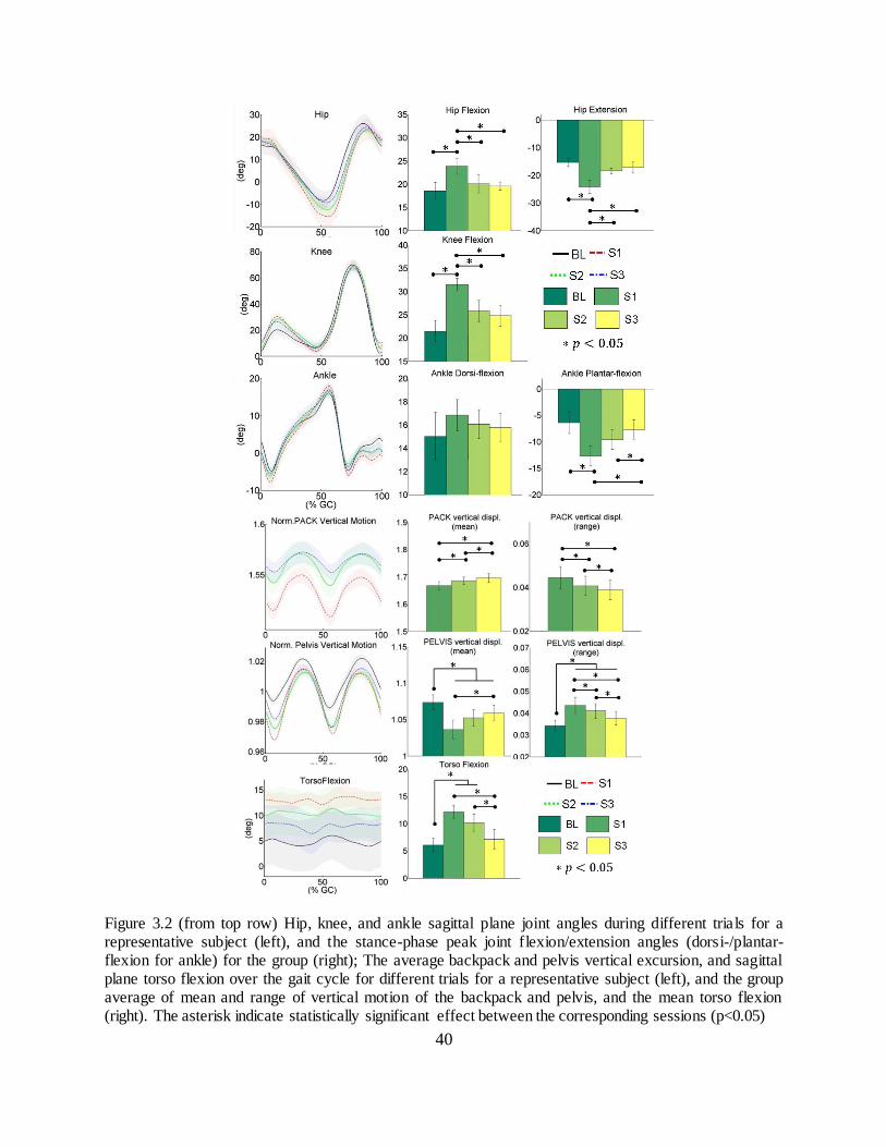
40
Figure 3.2 (from top row) Hip, knee, and ankle sagittal plane joint angles during different trials for a representative subject (left), and the stance-phase peak joint flexion/extension angles (dorsi-/plantar- flexion for ankle) for the group (right); The average backpack and pelvis vertical excursion, and sagittal plane torso flexion over the gait cycle for different trials for a representative subject (left), and the group average of mean and range of vertical motion of the backpack and pelvis, and the mean torso flexion (right). The asterisk indicate statistically significant effect between the corresponding sessions (p<0.05)

41
3.4.2 Spatiotemporal parameters
The average temporal parameters of gait are shown in Figure 3.3. Carrying a backpack
load without DLC (S1 and S2) significantly increased the double support period (DS) over that
of unloaded walking (BL). With DLC (S3), DS was significantly reduced from load only (S1).
The increase in DS decreased the single support period (SS) for all loaded cases as compared to
BL. SS also showed significant difference between all loaded sessions. Stance/swing ratio
increased with the backpack load (S1) as compared to BL and the other two loaded cases (S2 and
S3). It is worth noting that all of these changes due to the backpack load were significantly
attenuated (i.e., less deviation from their baseline values) when subjects carried the same
backpack load but with DLC (between S1-S3). Stride length and toe clearance showed a
decreasing tendency in S1 compared with BL while cadence had an increasing tendency in S1
compared with BL. These changes due to the backpack load were reduced in S2 and further
reduced in S3, with respect to S1, however, these changes were not statistically significant, Table
3.1.
Table 3.1. Comparison on the kinematics and spatiotemporal variables between sessions (n=12)
* BL S1 S2 S3 p value
S1-S2 S1-S3 S2-S3
Hip Flex.a
18.6 23.9 20.1 19.6 * * 0.89
Hip Ext. a -15.3 -24.1 -18.4 -17.2 * * 0.46
Knee Flex. a 21.5 31.5 25.8 24.8 * * 0.40
Ankle DorsiF. a 15.0 16.9 16.1 15.8 1.00 1.45 1.56
Ankle PlantarF. a -6.4 -12.7 -9.6 -7.7 0.09 * *
Pack V.mean b
n/a 1.668 1.686 1.696 * * * Pack V.range
b n/a 0.044 0.041 0.039 * * *
Pelvis V.mean b 1.074 1.036 1.052 1.059 0.05 * 0.08
Pelvis V.range b 0.034 0.044 0.041 0.038 * * *
Torso Flex. a 6.1 12.1 10.2 7.1 0.13 * *
DS c
15.0 16.9 16.5 15.9 0.09 * 0.08
SS c 34.9 32.0 33.3 33.7 * * *
Stance/Swing d
1.834 1.998 1.916 1.886 * * 0.06

42
Stride Length b 1.197 1.138 1.147 1.181 0.19 0.06 0.21
Cadence e
97.6 101.0 99.5 98.2 0.56 0.10 0.52
Toe Clearance b 0.130 0.123 0.125 0.128 0.19 0.11 0.11
Units: a) degree(°); b) normalized to subject’s leg length (unitless); c) percentage of gait cycle [%GC]; d) stance period/ swing period (ratio); e) steps/min
Figure 3.3 Group average temporal parameters: double support (DS), single support (SS), and stance/swing ratio
3.4.3 Ground reaction forces
Vertical ground reaction forces
The weight normalized vertical ground reaction force ( for a representative subject,
and a group average of its peak, time integral, and loading rate are shown in Figure 3.4. These
parameters were all significantly higher in the loaded sessions compared to BL. These expected
results reflect peak vertical forces during the weight acceptance phases due to the added mass on
the body. Interestingly, significant differences in these values were observed between different
loaded walking trials, i.e., between S1-S2, between S1-S3, and between S2-S3, except for the
vertical impulse value between S2-S3 which did not show significance, Table 3.2. These
results indicate reduced vertical ground reaction force components, in terms of its peak, impulse,
and loading rate was achieved with LD, and these were further reduced when DLC was provided.
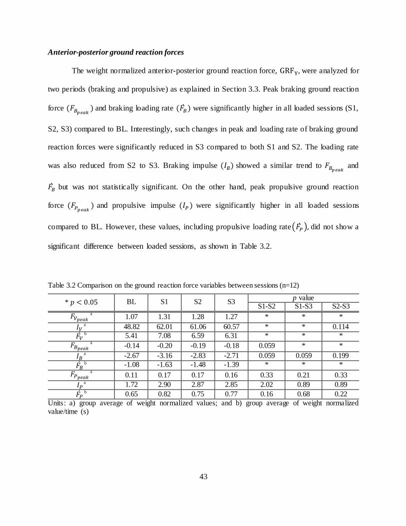
43
Anterior-posterior ground reaction forces
The weight normalized anterior-posterior ground reaction force, were analyzed for
two periods (braking and propulsive) as explained in Section 3.3. Peak braking ground reaction
force and braking loading rate were significantly higher in all loaded sessions (S1,
S2, S3) compared to BL. Interestingly, such changes in peak and loading rate of braking ground
reaction forces were significantly reduced in S3 compared to both S1 and S2. The loading rate
was also reduced from S2 to S3. Braking impulse showed a similar trend to and
but was not statistically significant. On the other hand, peak propulsive ground reaction
force and propulsive impulse were significantly higher in all loaded sessions
compared to BL. However, these values, including propulsive loading rate( ) did not show a
significant difference between loaded sessions, as shown in Table 3.2.
Table 3.2 Comparison on the ground reaction force variables between sessions (n=12)
* BL S1 S2 S3 p value
S1-S2 S1-S3 S2-S3
a 1.07 1.31 1.28 1.27 * * *
a 48.82 62.01 61.06 60.57 * * 0.114
b 5.41 7.08 6.59 6.31 * * *
a -0.14 -0.20 -0.19 -0.18 0.059 * *
a -2.67 -3.16 -2.83 -2.71 0.059 0.059 0.199
b -1.08 -1.63 -1.48 -1.39 * * *
a 0.11 0.17 0.17 0.16 0.33 0.21 0.33
a 1.72 2.90 2.87 2.85 2.02 0.89 0.89
b 0.65 0.82 0.75 0.77 0.16 0.68 0.22
Units: a) group average of weight normalized values; and b) group average of weight normalized value/time (s)

44
Figure 3.4 (a) Weight normalized vertical and anterior-posterior ground reaction force
during different trials for a representative subject; (b) peak ( , time integral of ( ,
vertical impulse), and vertical loading rate ( ; peak braking ( , time integral of negative
( , braking impulse), and braking loading rate ( ; peak propulsive ( , time integral

45
of positive ( , propulsive impulse), and propulsive loading rate ( values during a gait cycle are presented for the group.
3.4.4 Muscle activity and fatigue
The average iEMG and median power frequency (MPF) values of 6 recorded muscles
across the walking conditions are plotted in Figure 3.5. Activity of the rectus femoris (RF),
which is responsible for eccentric control of the knee flexion during weight acceptance, was
higher when subjects walked with a backpack load without DLC (S1 and S2), reflecting an
increased effort to control knee flexion during weight acceptance, but no significant difference
was found between BL and S3. The activity of RF and VL was reduced using DLC (S3) compare
to S1. MPF of RF reduced from BL in all loaded sessions. Differences in MPF were observed for
RF and VL between S1 and S3. Gastrocnemius medialis (GM), which provides foot plantar
flexion and knee flexion during push-off, showed higher activity when subjects walked with load,
reflecting increased efforts to provide a power-burst at push-off. Such an increase was reduced
from S1 for the other two loaded sessions. S1 showed an increase in muscle activation of the
soleus (SOL) compared to all other sessions. Changes in MPF of GM and SOL were not
significant between sessions, Table 3.3.
The activity of tibialis anterior (TA) was not significantly different when carrying the
load. Nonetheless, MPF of TA significantly decreased in S1 from BL, indicating muscle fatigue
induced by load carriage. MPF also indicates the fatigue on TA was less in LD and DLC
compare to the backpack only session. Three subjects’ erector spinae (ES) data were
contaminated possibly due to the interference from the backpack; hence, they are excluded in the
analysis. The activity of the ES was significantly lower for S1 than all the other sessions but no

46
significant differences were observed in the MPF of the ES between different sessions. The
activity of biceps femoris (BF) did not show a significant difference in both iEMG and MPF
values between different sessions, while the signal quality of the rectus abdominis (RA) and
upper trapezius (TRAP) were poor due to artifacts caused by fat deposits (RA) and the
interference from the shoulder straps (TRAP); hence they are not presented.
Table 3.3 Comparison on the muscle activity (iEMG) and mean power frequency (MPF) between sessions (n=12)
* BL S1 S2 S3 p value
S1-S2 S2-S3 S1-S3
iEMG a
RF 0.59 0.97 0.89 0.84 0.19 0.33 *
VL 0.72 1.10 1.01 0.94 0.11 0.06 * GM 0.74 0.96 0.89 0.85 * 0.13 *
SOL 0.74 0.99 0.85 0.82 * 0.67 * TA 0.69 0.94 0.83 0.78 0.08 0.07 0.08
ES 0.80 0.58 0.65 0.72 * 0.17 *
MPF b
RF 109.1 87.5 98.5 99.6 0.09 0.40 * VL 91.8 78.0 83.3 85.3 0.42 0.37 *
GM 121.3 103.0 116.4 117.2 0.07 0.07 0.62 SOL 139.2 133.8 138.8 141.0 0.11 0.36 0.14
TA 102.2 96.3 101.2 101.5 * 0.81 * ES 89.0 57.8 68.6 68.2 0.49 0.49 0.93
Units: a) normalized on corresponding peak baseline value (unitless), and b) mean power frequency (Hz)

47
Figure 3.5 Average linear envelopes of EMG during different trials of a representative subject for 6 muscles (RF, VM, GM, SOL, TA, and ES), and group average of their integral (iEMG) and median power frequency (MPF)
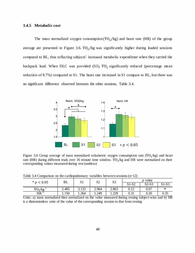
48
3.4.5 Metabolic cost
The mass normalized oxygen consumption and heart rate (HR) of the group
average are presented in Figure 3.6. was significantly higher during loaded sessions
compared to BL, thus reflecting subjects’ increased metabolic expenditure when they carried the
backpack load. When DLC was provided (S3), significantly reduced (percentage mean
reduction of 8.7%) compared to S1. The heart rate increased in S1 compare to BL, but there was
no significant difference observed between the other sessions, Table 3.4.
Figure 3.6 Group average of mass normalized volumetric oxygen consumption rate ( /kg) and heart
rate (HR) during different trials over 16 minute time window. /kg and HR were normalized on their corresponding values measured during rest (unitless)
Table 3.4 Comparison on the cardiopulmonary variables between sessions (n=12)
* BL S1 S2 S3 p value
S1-S2 S2-S3 S1-S3
/kg a 2.485 3.133 2.964 2.863 0.12 0.07 *
HR b
1.150 1.264 1.249 1.229 0.31 0.20 0.35 Units: a) mass normalized then normalized on the value measured during resting subject-wise and b) HR is a dimensionless ratio of the value of the corresponding session to that from resting

49
3.5 Discussion
3.5.1 Reduced vertical excursion of backpack load
The peak vertical excursion of backpack was reduced between each loaded session, as was the
goal of the device. This effect is the result of the passive suspension and is further improved with
active compensation of the dynamic load. The device also resulted in an elevation of the mean
vertical position of the backpack as it creates a gap between the shoulders and the shoulder pads,
and DLC reduced the vertical excursion of the backpack while not affecting the peak vertical
position from LD. The effect of this reduction in backpack motion is the main source of the
changes discussed in the following sections.
3.5.2 Changes in gait and postural adaptations
While walking with load may necessitate changes in gait to produce stable walking, it
may also be assumed that for each individual, their gait pattern has reached some optimization
based on their body size, joint stiffness, susceptibility to injury, etc. From this statement, it can
be reasoned that being able to reduce the effect of the load on the person and return them to a
gait pattern closer to unloaded walking may reduce problems associated with load carriage. In
line with previous studies on carrying a backpack load [12, 17, 28, 29, 35], subjects significantly
increased stance-phase peak knee flexion and hip flexion of the leading leg, and hip extension of
trailing leg when they walked with the backpack compared to unloaded walking. Gait kinematics
support the idea that LD and DLC are capable of creating a gait more similar to unloaded
walking as both S2 and S3 had peak angles of the hip and knee which were significantly
different than S1 in the direction of BL. This can be most heavily attributed to LD as these

50
values of S2 and S3 were not significantly different from each other. However, the contribution
of DLC is the primary factor in reducing ankle plantar flexion angle which occurs just following
heel strike. This is tied to the reduction in peak vertical GRF at heel strike which was reduced
with LD and further reduced with DLC, and which contributes to ankle plantar- flexion. The TA
slows the change in ankle angle after heel strike to prevent excessive plantar- flexion, and so the
reduction of TA fatigue in S2 and S3 may also be the result of reduced peak vertical GRF.
The increase in vertical pelvic excursion in the loaded sessions is related to the hip
extension angle assuming an inverted pendulum model, as well as increased knee flexion at heel
strike. Increased knee flexion at weight acceptance is associated with applying a braking force
and distributing it over a longer time to reduce high impact loading of the body, ca using a less
rapid deceleration of the mass and as a result reducing the force seen by the body. This is in line
with previous findings that the vertical excursion of pelvis increased with load carriage mainly
due to lowering of the COM of the body during weight acceptance phase to increase body
stability while absorbing the impact forces at heel strike [89]. These adaptations are shock
absorbing strategies used by the human motor system to attenuate the increased impact forces at
initial contact due to the added mass [17, 18, 19, 89, 90] and, in part, smoothen the transition of
the weight in the forward direction during the early mid-support phase [16, 17, 22, 89]. With the
load moving with the body (S1), the increased knee flexion achieves this purpose, which results
in an increase in double support period, consistent with the previous studies [17, 22, 27, 89].
When the load is able to move separately, this compensation at the knee is reduced in S2
as the deceleration of the load is, to some extent, taken by the spring suspension, and further
reduced in S3 when dynamic load was compensated. This is the result of the pack load having a
smaller vertical excursion over the same frequency of walking; thereby less force is needed to

51
accelerate and decelerate the mass. This is further supported by the vertical and braking GRF,
both in terms of the peak and loading rate. The reduction in these values could be caused by
increasing knee flexion angle and double support period. However, knee flexion and double
support period are reduced for S3, as are the peak and loading rates for the vertical and braking
force. These reductions can then be accounted for by the use of the device and not through
compensation at the knee. This is further supported by the reduction in knee extensor activity in
S3. The trend of reduced stride length indicates that the increased hip extension is a result of the
increased knee flexion for braking and also accounts for the vertical excursion of the pelvis. As
the knee flexes with both feet on the ground, the contralateral hip must extend to account for the
change which, in turn, lower the pelvis.
Reduced changes in temporal parameters also reflect a return towards unloaded gait
characteristics. The addition of loads, both gravitational and dynamic, requires additional time to
shift the loads over the base of support, thus, an increased stance time is typical in load carriage
which is caused by increasing the double support period while decreasing the single support
period [17, 22, 31, 89]. Such adaptations help shifting the load from one leg to the contralateral
leg during the transition from the double support to single support phase (mid-stance), thereby
enhancing body’s stability during load carriage [16, 17, 27, 90]. In accordance with the literature,
subjects significantly increased their double support period while decreasing single support
period when they carried the backpack thereby resulting in a higher stance to swing ratio.
This increase in time to shift loads may be linked with the reduction in the unilateral
activation of the ES, i.e., the left and right side of the ES do not activate at the same time. In
unloaded walking, there is a large spike in the ES on the side of the push-off leg, as the pelvis
shifts over and tilts obliquely to the stance leg. The ES acting unilaterally, as can be seen by the

52
single spike in activation during push off, is responsible for lateral flexion of the spine which
helps keeping the posture upright to account for the pelvic tilt and shift. When loaded only (S1),
the unilateral ES activation is decreased. This may be the result of having the weight supported
solely by the shoulders, in which case lateral flexion of the spine would cause motion of the load
and require increased energy to shift it from side to side as well as balance the moving load.
When the device is used, the load is partially supported by the pelvis allowing the shoulders to
more freely move. This freedom from load would then reduce the effect of the load on the torso
reducing the penalty for swinging. Previous study have reported a bilateral reduction in ES
activation (both left and right ES activations reduced) with backpack carriage and attributed it to
the backpack producing a torque as would be supplied by the ES [35]. While they report
reduction in ES activation, it is not clear if the activation was bilateral (both muscles activate at
the same time). Hence, the above claim made on the changes in the ES activation stands only as
a theory.
Similarly other studies have reasoned along the same lines, where walking with a
backpack increases forward lean of the trunk to bring the backpack mass close to the body COM
to maintain the combined COM of the upper body and carried load over the feet [12, 18, 27, 90],
and to keep the backpack COM lower to increase the stability of the body-plus- load system [17,
27, 89]. Our results do not seem to reflect this idea. With LD and DLC, torso flexion was
decreased while the mean pack position also increased as well, which are in line with the
previous findings [35, 91]. On the other hand, the change in the mean vertical position of
backpack between sessions was 1 to 2 cm, and this small change does not seem to account for
the changes in torso flexion angle we observed. It is more likely that the load distribution and
load pathway play a greater role on the changes in torso flexion. Bloom et al. observed that the

53
use of a hip belt with a pack reduces flexion angle [91]. A hip belt alone would not change the
COM location or the extension torque about pelvis created by the posterior offset of backpack
COM. Then, the change in flexion angle could be due to the reduction of the force transmitted
through the spine. Small torso flexion reduces lordosis of the lumbar spine, which changes how
load is transmitted between vertebrae. It has been shown that compressive follower loads, i.e.,
loads tangent to the curve of the spine, increase the load capacity of the spine in-vitro [92]. With
a reduction in lordosis due to torso flexion, the vertical component of the backpack load acts
more tangent to the curve of the spine increasing the load carrying capacity without straining the
soft tissue. This strategy can be thought of as an alternative reason why one might flex more
when loaded through the shoulders. By reducing the force transmitted through the spine by
distributing it with the pelvis, and then further reducing the dynamic loads, subjects do not need
to change postures to increase the load carrying capacity of their spine.
3.5.3 Metabolic benefits
One of the hypotheses of this experiment was that by using the device to reduce the
dynamic loads of a backpack we would be able to see a metabolic benefit from the user, even if
the session was only 15 minutes long. This hypothesis is based on previous work which found
that backpack load induces significant peak dynamic forces on the body and increases the
metabolic cost of walking [13, 20]. Recent studies showed that reducing suspension stiffness of a
backpack reduces the peak dynamic forces acting on the body [37, 93, 36]. Rome et al. also
showed a decrease in the peak vertical dynamic force (82%) and metabolic cost (6.2%) by
reducing the vertical motion of a backpack with respect to the human body [38]. Depending on
the suspension stiffness values, it induces in-phase (very compliant) or out-of-phase (stiffness

54
tuned to be in near-resonance with walking) motion of the backpack with respect to the body
motion. Studies have shown a reduction [38] or an increase [37] in metabolic cost as a result.
This is consistent with our finding of an 8.7% reduction in consumption between S1
and S3 with reduced backpack vertical excursion. This is higher than what was reported with
using a “suspended- load” backpack (6.2%) [38] or a flexible pack (3.8%) [37]. Such a difference
may be attributed to the load distribution between the shoulders and the pelvis. A backpack
frame and hip belt was shown to transfer 30% of load from the shoulders to the pelvis regardless
of load magnitude between 14 and 41 kg [94]. If a hip belt was used in a “suspended-backpack”
design, the load distribution between the shoulders and the pelvis would still be similar to that of
a frame backpack with a hip belt. Thus, the higher metabolic saving presented in this study may
suggest that more equally distributed load between the shoulders and the pelvis can further
increase the metabolic efficiency. This reinforces the findings of Grabowski et al. where the
vertical excursion of upper torso in human gait requires work from the lower limb to redirect and
accelerate body mass. This extra work incurs a significant metabolic cost during normal walking
and the additional load on the upper torso further necessitates a higher energy cost [95].
Contributing factors to this reduction are the reduction of knee extensor activation at
weight acceptance and reduced activation of the ankle plantar flexors. While reduction in plantar
flexors did not show a change in propulsive ground reaction forces, their lower activation would
still contribute to reduced oxygen consumption. The HR increased BL to S1, but only a
decreasing trend was found from S1 to S3, hence, HR will not be further discussed as it adds
little to the overall discussion of the metabolic benefits.

55
3.5.4 Reduced risk factors for injury
Reducing injury is a major concern with load carriage, particularly in applications for
which this device was designed. The most direct risk factor for injury which has been reduced
with the use of the device is the reduction in peak and loading rate of the vertical and braking
GRF. This has the implication of lower impact force on the feet and the joint loading rate which
can potentially reduce repetitive strain injuries on the lower limbs, such as stress fractures, foot
blisters, muscle soreness, etc. [12, 14, 16, 17]. Similarly, reduced lower limb muscle activity and
muscle fatigue while using the device can reduce the potential muscle strain and overuse injuries.
Fatigue of the TA reduces ground clearance which may lead to tripping. TA fatigue is reduced
with the device which can lower the possibility of this occurring. Additionally, the fact that the
lower limb muscle fatigue was reduced with the device in addition to the net metabolic benefit
implies general fatigue would lessen as a result of physical exertion.
Another important result is the reduction in torso flexion. It is thought that the reason for
this change in torso flexion is to bring the combined COM over the base of support [12, 27, 90].
However, an increase in forward lean has been hypothesized to cause stress on the back muscles,
ligaments, thereby leading to back injuries [12, 15, 6, 89]. With LD, torso flexion was reduced
from S1 and this was further reduced by DLC. This may reduce the prevalence of back injuries.
Distributing the load between the shoulders and pelvis attenuates the pressure on the shoulders
and spine. This may reduce incidence of rucksack palsy, lower back pain, etc. [12, 13, 18].

56
3.6 Conclusion
In this chapter, the WEBS was tested on twelve human subjects to address the following research
question, “What are the biomechanical and physiological effects of load distribution and
dynamic load compensation of a backpack on the human body during backpack load carriage?”
It was hypothesized that load distribution and dynamic load compensation during backpack load
carriage, gait and postural adaptations typical in backpack load carriage, and the user’s muscular
effort and metabolic cost would be reduced. This hypothesis was supported by biomechanical
and physiological measurements on a group of young healthy subjects, as they walked on a
treadmill under 4 different conditions: unloaded, with a backpack load of 25% of their body
weight supported on the shoulders, with the same load distributed between the shoulders and the
pelvis, and with dynamic load compensation in addition to load distribution.
The experiment protocol was described in Section 3.2. Section 3.3 presented statistical
analysis method carried out on dependent variables using a repeated measure ANOVA technique
to determine the statistically significant differences of dependent variables between conditions.
The results presented in Section 3.4 revealed the effects of load distribution and dynamic load
compensation: reduction in gait and postural adaptations, muscle activity, vertical and braking
ground reaction forces, and metabolic cost. Based on these results, Section 3.5 discussed the
potential of the wearable upper body suit to reduce the risk of musculoskeletal injuries and
muscle fatigue associated with heavy backpack loads, as well as reducing the metabolic cost of
loaded walking.

57
Chapter 4
Robotic Spine Exoskeleton (ROSE) for correction of
spine deformities
4.1 Introduction
In this work, the torso exoskeleton, Robotic Spine Exoskeleton (ROSE), was designed to
overcome the limitations of current spine braces due to their rigid, static, and non-sensorized
designs. The ROSE consists of two parallel robotic platforms connected in series that can snugly
fit to different cross-sections of a human torso. It has a total of twelve active degrees of freedom
and can dynamically modulate either the posture of or the forces applied to different cross
sections of the human torso. The chapter is organized as follows. Section 4.2 describes the
architecture and the design process of the ROSE. Section 4.3 details the position and force
controller implemented in the ROSE. Section 4.4 demonstrates the performance of the two
controllers through experimental evaluation. Section 4.5 summarizes and concludes the chapter.
4.2 Design
The ROSE consists of three rings which can be adjusted to fit snugly on the human body, at the
pelvic, thoracolumbar, and thoracic regions of the torso, Figure 4.1(a). A six degree-of-freedom
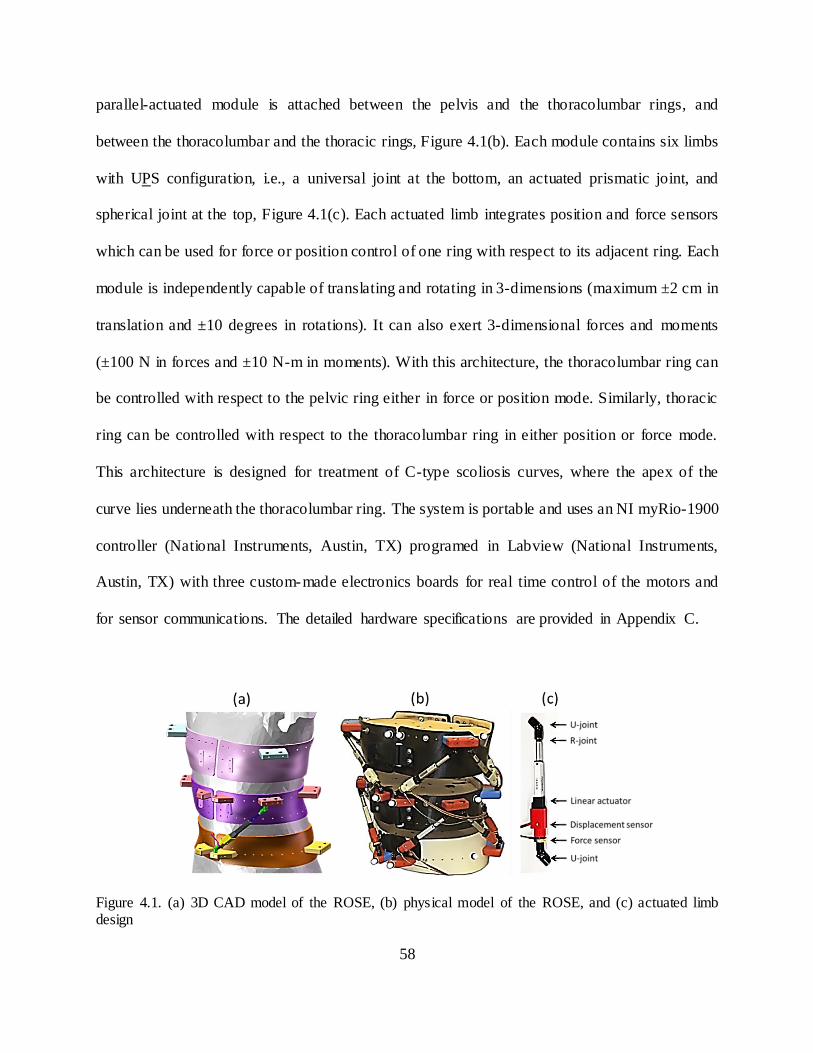
58
parallel-actuated module is attached between the pelvis and the thoracolumbar rings, and
between the thoracolumbar and the thoracic rings, Figure 4.1(b). Each module contains six limbs
with UPS configuration, i.e., a universal joint at the bottom, an actuated prismatic joint, and
spherical joint at the top, Figure 4.1(c). Each actuated limb integrates position and force sensors
which can be used for force or position control of one ring with respect to its adjacent ring. Each
module is independently capable of translating and rotating in 3-dimensions (maximum ±2 cm in
translation and ±10 degrees in rotations). It can also exert 3-dimensional forces and moments
(±100 N in forces and ±10 N-m in moments). With this architecture, the thoracolumbar ring can
be controlled with respect to the pelvic ring either in force or position mode. Similarly, thoracic
ring can be controlled with respect to the thoracolumbar ring in either position or force mode.
This architecture is designed for treatment of C-type scoliosis curves, where the apex of the
curve lies underneath the thoracolumbar ring. The system is portable and uses an NI myRio-1900
controller (National Instruments, Austin, TX) programed in Labview (National Instruments,
Austin, TX) with three custom-made electronics boards for real time control of the motors and
for sensor communications. The detailed hardware specifications are provided in Appendix C.
Figure 4.1. (a) 3D CAD model of the ROSE, (b) physical model of the ROSE, and (c) actuated limb design

59
Figure 4.2 The design process of the robotic spine brace; Step 1: 3D scan of the body, Step 2: superimpose the spine 3D CAD to the 3D scan of the body, Step 3: design the rings of the ROSE, Step 4: determine the location of the rings and actuators and optimizing the workspace, Step 5: fabrication and calibration
Figure 4.2 illustrates the design process of the ROSE. In Step 1, a 3D scan of the human
torso is obtained by optical scanning. In Step 2, a 3D CAD model of the human torso is
constructed using the 3D scan data. Then, a 3D CAD model of the spine is scaled and
superimposed to obtain the approximate location of the spine vertebrae on the torso model. In
Step 3, the locations and sizes of the three rings are determined. Then, 3D CAD models of the
rings are designed to fit snugly on to the human torso at the pelvis, thoracolumbar, and thoracic
regions. In Step 4, the placements of the six limbs on the rings are optimized to achieve the
desired workspace between the rings. In Step 5, the rings and other mounting components are
fabricated (3D printing using ABS plastic material) and assembled. Finally, the ROSE is
calibrated on a person by adjusting the initial positions of the rings and tuning the control gains.

60
4.3 Control
Two control modalities – position control and force control – are implemented at the joint space.
Sensors on each limb give real time joint position and force feedback to the controller that allows
for closed- loop control in either mode. The upper and lower parallel platforms are controlled
independently. The control topology for position and force control are shown in Figure 4.3 and
Figure 4.4, respectively. Parameterization, kinematics, and trajectory planning of the ROSE are
described in Appendix D.
The position controller consists of a high level controller and a low level controller,
Figure 4.3. The trajectory planner first generates the desired motion of the platform. The high
level controller then maps the desired motion of the platform in Cartesian space ( into the
joint space variable at 200 Hz using inverse kinematics. [ ]
is the
vector of pose variables of the moving platform and [ ] is the vector of
actuated joint. Part of the high level controller also computes the Cartesian position and force
vectors, and , of the platform using the joint position/force feedback via forward kinematics
and the robot’s Jacobian. This allows the Cartesian forces of the platform to be measured during
position control. The low level controller, consisting of individual PID controllers for each joint,
receives the desired joint position from the high level controller and performs the closed- loop
control on the joint position at 500 Hz. The error is measured as the difference between the
desired joint position and the actual joint position. The controller gains of each actuator were
experimentally tuned.

61
Figure 4.3 Position controller implemented in the joint space; IK and FK represent inverse kinematics and forward kinematics, respectively, and J represents Jacobian
The force controller, Figure 4.4, consists of a high level and a low level controller similar
to the position controller topology. The high level controller, implemented at 200 Hz, maps the
desired force in task space to the desired joint forces using the formula
assuming non-singular configurations within the operating workspace where
[ ] is the vector of actuator forces, and [ ]
is the vector
of output Cartesian forces from the robot. Such a mapping uses the robot’s Jacobian in its current
configuration which is calculated in real time using joint position feedback. This allows the
Cartesian forces to be controlled based on the pose. The low level controller receives the desired
joint forces computed in the high level controller, and uses an open loop reference feed-forward
(FF) term with unit gain and a closed-loop PID term to follow the desired forces of
each joint. The unit gain for the FF term and PID gains were experimentally tuned.

62
Figure 4.4 Force controller implemented in the joint space; FK and J represent forward kinematics and Jacobian, respectively.
4.4 Controller Evaluation
This section presents experimental evaluations of position and force controllers implemented in
the ROSE. The linear actuator in each limb of the ROSE has an integrated potentiometer that
feedback the joint displacement from which the Cartesian pose of each ring is computed using
forward kinematics. Infrared markers were placed on the rings to measure their position and
orientation with a motion capture system (Vicon Motion Systems®, Oxford, UK). The position
controller was evaluated by moving the ROSE through seven different modes of motions: 3-
point-pressure motion, flexion, lateral bending, rotation follow, rotation mirror, translation
follow, and translation mirror. The 3-point-pressure mode mimics the traditional 3-point-pressure
correction method used in the spine braces which involves rotation about z and translation about
x in the transverse plane. Flexion and lateral bending modes evaluate the bending motion
capability in a brace. The last series of modes were carried out for isolated translations and
rotations. In these modes, the upper parallel-module performed either the same task (follow) or
the opposite task (mirror) as the lower parallel-module.

63
The motion was recorded through potentiometers on the motors as well as the motion
capture system where the translation and rotation of the middle and top segments relative to the
neutral position were recorded and analyzed with respect to the bottom coordinate frame. Figure
4.5 shows motion tracking results verified using a motion capture system for 3-point-pressure
motion trial. The position controller was able to follow all paths with less than 0.98° of average
error for all tested trajectories, Table 4.1. For translational motions, the average positioning
errors were in the sub-millimeter range.
Figure 4.5 Graphical representation of the command (dashed) and Vicon (solid) results from the 3-point motion test. Rotations and translations about x, y, and z are represented by black, red and blue respectively; (top row) the lower parallel-module and (bottom row) the upper parallel module

64
Table 4.1 Position and orientation error of the middle and lower segment origin from seven motions tested
The force controller evaluation utilized a test bed wherein the middle and bottom
segments were attached to each other using a 6-axis force/torque sensor (Mini45, ATI) in the
brace’s neutral position to measure the relative force and moment in a given pose of the middle
segment relative to the bottom segment, Figure 4.6. The brace was then driven to follow a
force/torque profile: (1) unidirectional force or torque; -30 N < < 30 N and -1.5 Nm ≤
≤ 1.5 Nm, 2) and (2) three dimensional force and torque ( ). The calculated
force/torque from the load cells in the brace were then compared to the force/torque sensor data
to determine sensor error, and were also compared to the commanded force/torque profile to
evaluate tracking error. Figure 4.7 shows a representative force tracking result when a set of
planar desired forces and moments were commanded to the system. Both uni-directional and
three dimensional force control demonstrated good tracking performances with less than 4% and
7% tracking errors, respectively.

65
Figure 4.6 Test-bed for force controller evaluation
Figure 4.7 (right) Graphical representation of the command force (dashed-black) and measured force (solid-blue) from ATI F/T sensor; (a) One dimensional force, and (b) three dimensional force
4.5 Conclusion
In this chapter, the design, control, and evaluation strategies of the ROSE are presented. The
ROSE is capable of controlling and monitoring either the forces or the poses that it imposes on
the body in 3-dimensions. It consists of a series of rings that are snugly a ttached to the human
body and conform to cross sections in the torso. Forces and moments are applied to each ring
using actuators mounted on adjacent rings. The rings are parallel-actuated using the Stewart-

66
platform design with closed- loop control of the actuators using joint position/force data
measured by integrated sensors. These were described in Section 4.2 and Section 4.3. The
accuracy of tracking the commanded position or forces through two control modes was evaluated
experimentally using a camera based motion capture system and using six axis force-torque
sensor which showed good tracking performance (demonstrated in Section 4.4). The next chapter
will present the human subject study conducted using ROSE to evaluate the feasible range of in-
brace torso motion, the ability to control forces applied on the human torso at various postures,
and the feasibility of characterizing the three dimensional stiffness of the human torso.

67
Chapter 5
Experiment of ROSE with human subjects
5.1 Introduction
This chapter presents the human subject experiment using the ROSE to evaluate the feasible
range of torso motion while wearing ROSE, controlling a constant force at various postures, 3-
point-pressure correction, and characterizing three-dimensional torso stiffness. Ten healthy male
adults (age 29±6 years, height 1.73±0.05 m, torso length 0.31±0.046 m, and weight 73.2±4.5 kg)
participated in this study. The experimental protocol was approved by the Columbia University
Institutional Review Board and informed consent was obtained from all participants before
conducting the experiments. All subjects were between 18 and 35 years of age without any
history of back pain or spine injuries, cardiopulmonary conditions, neurological or physical
impairments, or other orthopedic conditions that could affect natural motions of the torso and the
spine.
The chapter is organized as follows. Section 5.2 presents the protocol and methods used
in the experiment. Section 5.3 presents the results. Section 5.4 discusses the results and
limitations of the study. Section 5.5 concludes the chapter.

68
5.2 Protocol
The study consisted of four sessions with the length of each session and breaks between
sessions shown in Figure 5.1(a), and the coordinate frame used in the study shown in Figure
5.1(b). All sessions were performed with the subjects in a relaxed, seated position. Before the
beginning of the first session, the size of the brace was adjusted to fit the subject, and then any
gaps between the brace and the body were filled with padding.
Figure 5.1. (a) Human subject experiment protocol and (b) torso coordinate frame used in this study
Session 1 (S1) measured the feasible range of torso motion during in-brace and no-brace
conditions. A motion capture system (Vicon Motion Systems®, Oxford, UK) was used to record
torso kinematics, Figure 5.2. Reflective markers were placed on the subjects’ anterior superior
iliac spines, sacrum, sternoclavicular joints, and the inferior border of the manubrium. For each
of the two conditions, subjects were asked to move their torso as far as they could in frontal
(lateral bending), sagittal (flexion/extension), and transverse (vertical rotation) planes. During in-
brace range of motion (ROM) testing, the brace was nearly transparent to users and applied

69
minimal forces on their body. The maximum angle between the pelvis and the sternum for six
directions were compared between in-brace and no-brace conditions.
Figure 5.2 Session 1: the range of motion test with and without the ROSE
The second session (S2) evaluated constant force control at various postures of the torso.
While allowing for a wide range of natural motion of the torso without exerting a force is a good
feature to have to allow user’s activities of daily living (ADL), it doesn’t correct scoliotic spines.
Therefore, if corrective forces can be provided to the torso in various pose configurations,
treatment effect can also be achieved. To validate this idea, a constant force ( ) was
commanded while the subject was wearing the brace and performing the same range of motion

70
test in S1. Forces were measured during these motions and compared with those measured
during S1 (transparent mode).
The third session (S3) evaluated a spine correction method called “3-point-pressure”,
which is used in most rigid braces [63]. This method applies corrective forces at the apex of the
abnormal curves of the spine, particularly by applying translational and rotational displacements
in the transverse plane. Our aim was to apply the same method on healthy individuals using
ROSE, and evaluate the forces exerted on the torso. To do this, the middle segment
(thoracolumbar ring) of the brace was positioned at the subject’s T-10 vertebrae level and the
brace controlled the displacement of this segment about the transverse plane (x, y) and the
rotation about the z axis (ψ) with respect to the bottom segment. The top segment was controlled
to be held in a stationary position with respect to the bottom segment, Fig. 8. Six different values
of displacements were applied at the same time in , , and : translation from -7.5 to 7.5 mm in
2.5 mm intervals, and rotation from -0.075 to 0.075 radian in 0.025 radian intervals, Figure 5.3.
Each set of measurements was repeated three times and the measured forces were averaged over
the group.
Figure 5.3 3-point-pressure method evaluated using the ROSE; planar displacements were applied with varying magnitude and directions, and forces were measured

71
The capabilities of the ROSE allow us to explore the elastic behavior of human torso to
determine the force/displacement relationship of the human torso. To validate this idea, the
fourth session (S4) characterized the stiffness of the torso through a set of force-displacement
measurements. The ROSE applied unidirectional displacements at the T-10 vertebrae level of the
torso on the subject while the subject was sitting comfortably on a chair. Displacements were
applied individually for each degree of freedom from -15 to 15 mm in 5 mm intervals for
translation, and from -0.15 to 0.15 radians in 0.05 radian intervals for rotation. All other degrees
of freedom were fixed to the neutral position. As these displacements were applied, both position
and forces were measured simultaneously, for one second at 100 Hz. The collinear stiffness
terms were calculated by measuring the force collinear to the applied displacement. Each
displacement was repeated three times, and the mean and standard deviation of measured forces
were then calculated. The rate of displacement used in each test was 7 seconds per cycle,
consisting of 3 seconds of ramp (zero initial position to the desired displacement), followed by 1
second recording (at the desired displacement), then 3 seconds of ramp (desired displacement to
zero initial position) which was approximately 0.15 Hz per cycle to obtain quasi-static force-
displacement relationships. This speed is close to the lower range of the test speed (0.1 Hz)
recommended for spinal in vitro force-displacement testing [96]. The means and standard
deviations of collinear stiffness were obtained over the group.

72
5.3 Results
5.3.1 Feasible range of motion with the brace
The range of motion of the torso between in-brace and no- brace conditions were
compared, and the percentage of the subjects’ range of motion during in-brace test was
calculated with respect to the no-brace test. The results show that the subjects were able to
achieve a majority of their natural range of motion while wearing the brace, Figure 5.4. This
implies that the brace can accommodate many normal activities of daily living (ADL), such as
tying one’s shoes or picking something up from the ground.
Figure 5.4 Feasible range of motion while wearing the brace compared to subjects’ natural range of torso motion; (left) mean and standard deviation between the two conditions, and (right) average in-brace range of motion expressed as a percentage of no-brace range of motion

73
5.3.2 Constant force control during motion
In session 2, a constant force ( ) was controlled during motions and compared with
the forces measured during the same motions in the transparent mode (S1). The results showed
that in transparent mode (S1), the brace allowed torso motions while maintaining applied forces
close to zero. With constant force control (S2), the brace was able to maintain constant forces at
various torso poses and during transitional periods between poses. Some forces that were
controlled to be zero increased at the start and at the end of the motion but these were expected
transient responses. Once the motion reached steady-state (quasi-static pose), those forces started
decreasing and were reduced to zero, Figure 5.5. The mean values of the forces during the
motions under these two modes were averaged over the group, and mean and standard deviations
are shown in Figure 5.6. It was shown that for all subject tested, the magnitude of the controlled
forces was close to what was commanded, which validates performances of both the transparent
mode and constant force control mode. This result also suggests that the ROSE can correct
abnormal postures of the torso while allowing for a range of motions.

74
Figure 5.5 Comparison on forces exerted on the body during in-brace motions between transparent mode and constant force control mode of a representative subject
Figure 5.6 Group mean and standard deviation of the forces during six different in-brace motions between transparent mode and constant force mode

75
5.3.3 3-point-pressure validation
The group average for 3-point-pressure validation using the ROSE is shown in Figure 5.7.
As expected, the direction and magnitude of forces collinear to the input displacements (Fx, Fy,
Tz) were proportional to those of the input displacements. Interestingly, the planar displacements
not only resulted in collinear forces but also induced forces in other directions, specifically the
moment about x and y axes of the applied translational input displacements. This indicates
“coupling effects” of the forces between the degrees-of-freedom which suggests the need to
investigate 3-dimensional elastic behavior of the human torso when it is subjected to external
displacements.
Figure 5.7 3-point-pressure validation; planar displacements ( ) induced 3-dimensional forces

76
5.3.4 Stiffness characterization
The force-displacement relationship over the range of applied displacements was nearly linear
for all degrees-of-freedom. Figure 5.8(a) shows a representative subject. The collinear stiffnesses
averaged over the group are shown in Figure 5.8(b). The translational stiffness was highest in the
z direction (superior/inferior) followed by the stiffness in the x direction (medial/lateral) and then
the stiffness in the y direction (anterior/posterior). The rotational stiffness was highest in
direction (lateral bending) followed by the rotational stiffness in direction (axial rotation) then
the rotational stiffness in direction (flexion/extension). These trends found in the relative
magnitudes among the translational stiffnesses ( ) and rotational stiffnesses
( ψ
) were in accordance with those reported in the literature where the collinear
stiffness was experimentally computed through in-vitro human spine force-displacement
measurement [97, 4], Table 5.1. The agreement in these trends suggests that the human spine - as
it is the primary load bearing element of the torso - may be the biggest contributing factor in
determining the stiffness of the human torso.

77
Figure 5.8 (a) Force-displacement mapping of a torso at T-10 vertebrae level of a representative subject;
subscript followed by indicates the stiffness about the corresponding degree of freedom, and (b) Group mean and standard deviation of collinear stiffnesses of human torso at T-10 vertebrae location (n=10)
Table 5.1 Relative magnitudes of the translational stiffness terms and rotational stiffness terms measured from human torso in this study, compared with those measured from the spine vertebrae in other studies [97, 4]
The comparison of the magnitude of the collinear stiffnesses from the positive
displacement and the negative displacement may also suggest whether the body is symmetrical
about the neutral axis, e.g., asymmetry of lateral stiffness ( ) between two points mirrored

78
about the neutral pose (zero displacement) may be explained by asymmetry in spine or muscle
stiffnesses. If the slope of the stiffness curve doesn’t change over the neutral position, it may
indicate the symmetric stiffness of the torso about the body center.
Based on observed “coupling effects” between the degrees-of- freedom shown in the 3-
point-pressure validation results, it was logical to further investigate the three-dimensional
stiffness characteristics of the torso, which can be represented as a 6x6 stiffness matrix. The
stiffness matrix can be experimentally obtained by measuring the forces and moments associated
with each of the six orthogonal translations and rotations. For example, once the locations of the
pelvic and thoracolumbar rings are selected at a particular level of the human torso, the ROSE
can control the displacements of the thoracolumbar ring and measures the resulting forces. The
behavior is given by the formula , where is a vector of forces and moment applied to
the body through the brace ( [ ] , represents a small position and
orientation displacement of the ring in Cartesian space ( [ ] ), and
is the stiffness matrix to be experimentally determined. By conducting a series of experiments,
where known forces are applied and are measured or known are applied and resulting
forces are measured, one can estimate the stiffness matrix computationally through a linear
regression method (least square fit). Each measurement results in one linear equation relating
force to displacement, thus at least 36 different measurements are required to solve for 36
unknown entries of , (5.1).
[
] [
] [
] (5.2)
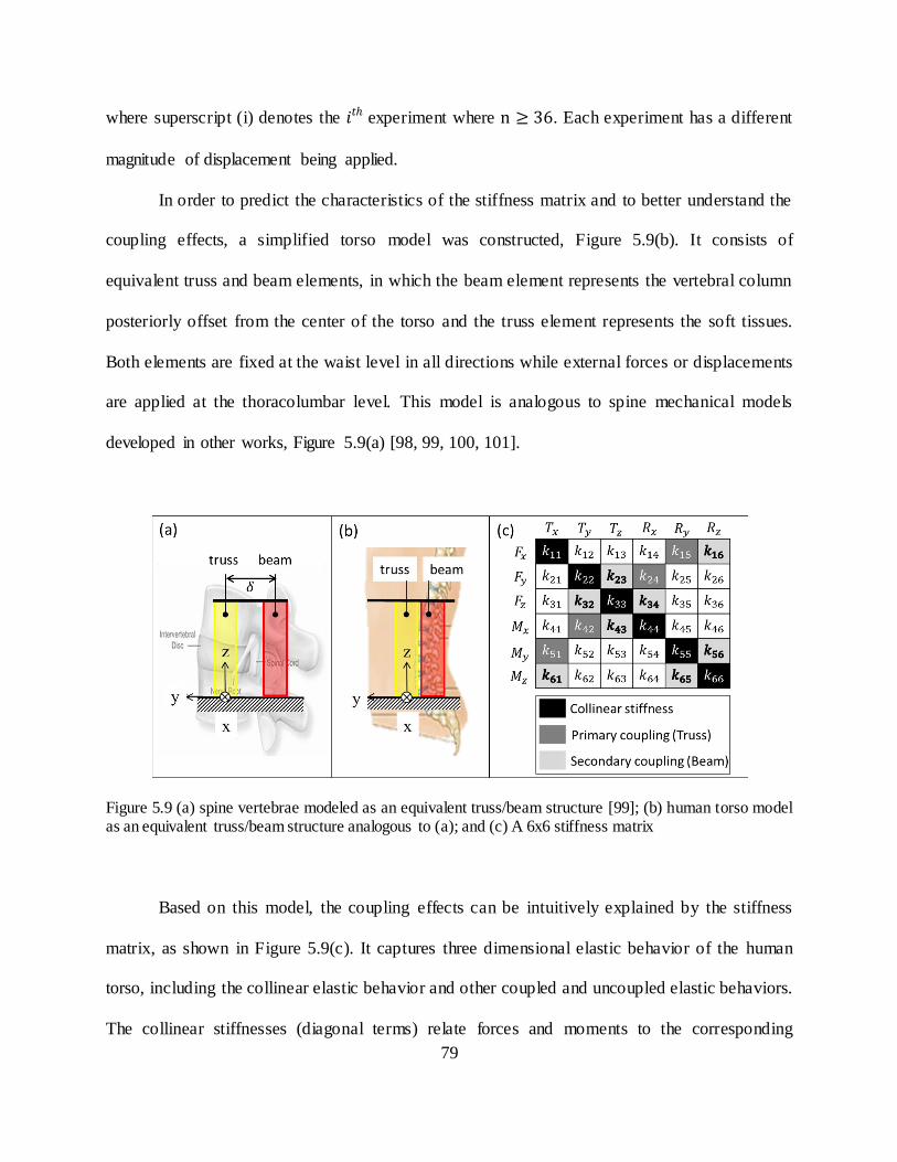
79
where superscript (i) denotes the experiment where . Each experiment has a different
magnitude of displacement being applied.
In order to predict the characteristics of the stiffness matrix and to better understand the
coupling effects, a simplified torso model was constructed, Figure 5.9(b). It consists of
equivalent truss and beam elements, in which the beam element represents the vertebral column
posteriorly offset from the center of the torso and the truss element represents the soft tissues.
Both elements are fixed at the waist level in all directions while external forces or displacements
are applied at the thoracolumbar level. This model is analogous to spine mechanical models
developed in other works, Figure 5.9(a) [98, 99, 100, 101].
Figure 5.9 (a) spine vertebrae modeled as an equivalent truss/beam structure [99]; (b) human torso model as an equivalent truss/beam structure analogous to (a); and (c) A 6x6 stiffness matrix
Based on this model, the coupling effects can be intuitively explained by the stiffness
matrix, as shown in Figure 5.9(c). It captures three dimensional elastic behavior of the human
torso, including the collinear elastic behavior and other coupled and uncoupled elastic behaviors.
The collinear stiffnesses (diagonal terms) relate forces and moments to the corresponding

80
collinear displacements (or vice versa). The dark-gray colored, off-diagonal terms are primary
coupling stiffnesses, which are induced by the truss element. For example, lateral force ( ) will
cause a translation in the , which is related to , and a rotation about the as the spine bends,
which is related to . The light-gray colored, off-diagonal terms are secondary coupling
stiffnesses which are induced by the beam element (spine) that offsets posteriorly from the center
of the torso. From the above example, the lateral force ( ) creates rotation about the axis due
to the beam effect, and this relationship is defined by . The un-shaded elements are more
minor couplings which would presumably be much smaller than the rest of stiffness terms.
Using the aforementioned method, 36 independent coefficients were calculated by
simultaneously solving 36 sets of linear equation using the linsolve function in Matlab
(MathWorks, Inc., Natick, MA, USA). Figure 5.10 shows the stiffness matrix computed from a
single subject. In a linear elastic conservative system, the stiffness matrix is symmetric on the
basis of Maxwell’s Reciprocity Theorem. The stiffness matrix of the human torso, however, was
not symmetric. This might be partly due to the nonlinear visco-elastic properties of the spine,
ligaments and soft tissues, and partly due to the non- isometric properties of human torso. This is
in line with recent studies [102, 103] where the experimentally obtained stiffness of the spinal
segment was non-symmetric.

81
Figure 5.10. Stiffness matrix derived from a single subject.
The stiffness matrix was computed for each subject. The general trends of the stiffness
matrix seen across the subjects are: (i) the primary coupling stiffness terms, those induced from
the truss effect, were most marked, (ii) the pair was generally higher than the
pair which indicates that the lateral shear force to the lateral rotation motion coupling is higher
than the anterior-posterior shear force to the flexion/extension motion coupling, (iii) the
secondary coupling stiffness terms, those induced from the beam effect, were less marked than
the primary-coupling stiffness terms, and showed inconsistencies in terms of relative magnitudes
and signs across the subjects, and (iv) the off-diagonal stiffness terms that were expected to be
negligible indeed showed much smaller magnitudes as compared to other terms.
In order to obtain more generalizable results that represent the stiffness matrix of the
whole group and to find the general tendency between terms, the stiffness matrices need to be
averaged. However, averaging each stiffness term individually will fail to capture the general
stiffness characteristics of the torso in terms of relative differences between the terms and

82
coupling effects for variations in stiffness between subjects were rather high. Therefore, each
stiffness matrix needs to be normalized to eliminate inter-subject variability with respect to the
magnitude of stiffness before computing an average. Several indices can be taken into
consideration in evaluating the stiffness matrix, e.g. determinant, trace norm, and eigenvalues of
the matrix. These indices can be used to normalize each element of the stiffness matrix.
However, the elements of the stiffness matrix are not dimensionally uniform; the upper
left 3x3 portion represents translational stiffness with the dimension of force/length, the lower
right 3x3 portion represents rotational stiffness with the dimension of force multiplied by length,
and the remaining portions of the matrix have the dimension of force. Because the stiffness
values are dimensionally non-uniform, normalizing the matrix before making it dimensionally
uniform is not mathematically valid. A method to derive a dimensionally uniform stiffness
matrix has been proposed in [104]. In this study, a similar approach was taken to obtain a
dimensionally uniform stiffness matrix. We first obtained the dimensionally uniform force vector
and position vector The first three components of have the dimension of force, whereas
the last three components have the dimension of force multiplied by length. On the other hand,
the first three components of have the dimension of length, whereas the last three components
are dimensionless (radians). In order to make F and X dimensionally uniform, we define
conversion matrix and respectively, which are 6 x 6 diagonal matrices given by
(5.3)
When is pre-multiplied to F, and similarly is pre-multiplied to X, we obtain dimensionally
uniform force vector and position vector as follow:
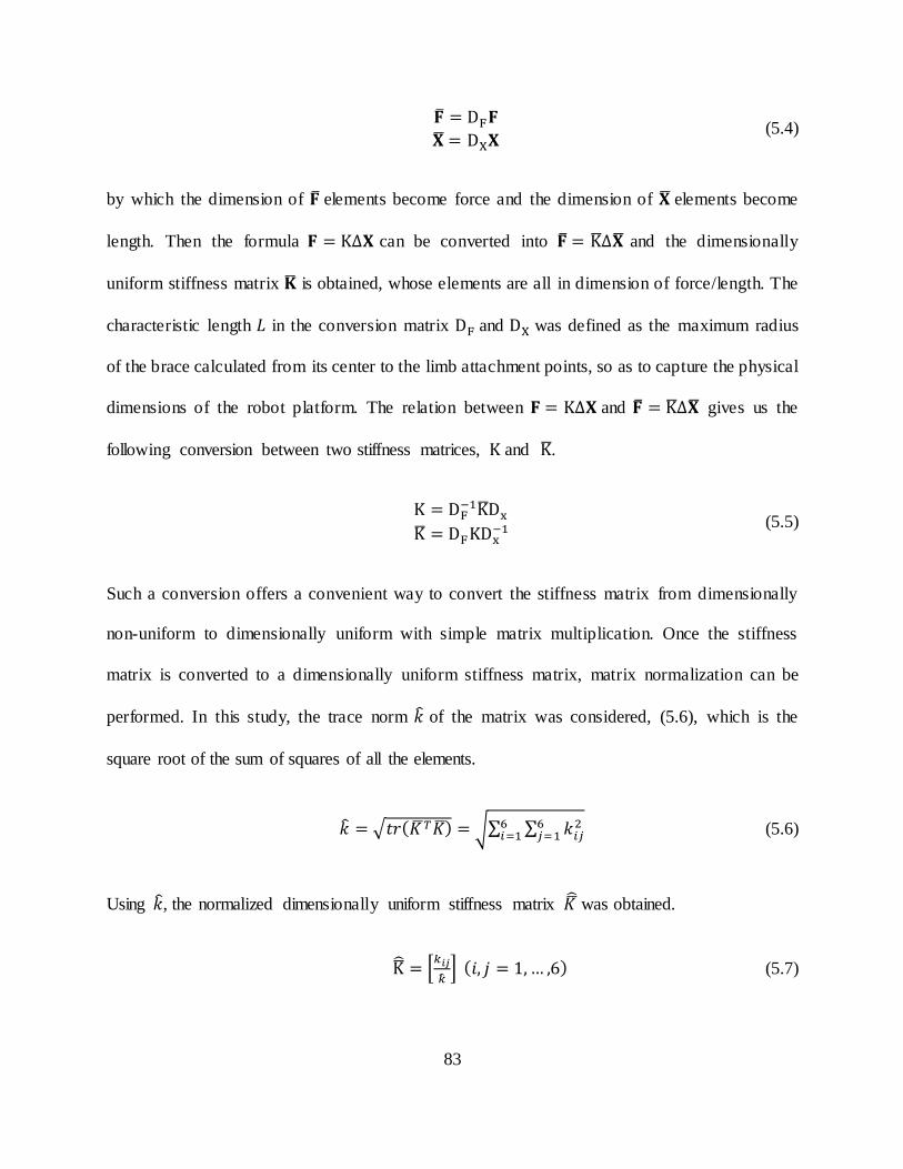
83
(5.4)
by which the dimension of elements become force and the dimension of elements become
length. Then the formula can be converted into and the dimensionally
uniform stiffness matrix is obtained, whose elements are all in dimension of force/length. The
characteristic length in the conversion matrix and was defined as the maximum radius
of the brace calculated from its center to the limb attachment points, so as to capture the physical
dimensions of the robot platform. The relation between and gives us the
following conversion between two stiffness matrices, and .
(5.5)
Such a conversion offers a convenient way to convert the stiffness matrix from dimensionally
non-uniform to dimensionally uniform with simple matrix multiplication. Once the stiffness
matrix is converted to a dimensionally uniform stiffness matrix, matrix normalization can be
performed. In this study, the trace norm of the matrix was considered, (5.6), which is the
square root of the sum of squares of all the elements.
√ √∑ ∑
(5.6)
Using , the normalized dimensionally uniform stiffness matrix was obtained.
[
] (5.7)

84
Then, the normalized stiffness matrix from each subject was averaged over the group. The results
are more consistent with the predicted characteristics of a stiffness matrix, where the primary
coupling terms were in agreement with the model, Figure 5.9(c), while mixed results were seen
in the secondary coupling terms (only terms showed consistency). The remaining off-
diagonal stiffness terms were comparably smaller, Figure 5.11(a). Once we obtained the group-
averaged normalized stiffness matrix, this matrix can be multiplied by the group mean of the
trace norm to retrieve the physical meaning of the stiffness matrix, then (5.5) is used to convert it
to the dimensionally non uniform stiffness matrix, Figure 5.11(b). This matrix represents the
three dimensional stiffness of the torso for our tested group.
Figure 5.11 (a) Normalized stiffness matrix (n=10); (b) stiffness matrix:
( ( ))

85
5.3.5 Sensitivity and Robustness of Stiffness Measurement
Stiffness variation in sitting and supine position
The collinear stiffness of the human torso measured from the above study were calculated
while the subject was in a seated position. Intuitively, the stiffness may vary depending on the
pose during which the measurements were taken as the gravitational force directed along the
torso would be different, for example between the seated and supine postures. Therefore, we
hypothesized that the torso stiffness measured through the brace is pose-dependent. To validate
this hypothesis, the same set of force-displacement experiment was repeated while the same
subject was in a supine position (T1 in Figure 5.12). In order to avoid the errors from any contact
forces other than human torso during force-displacement measurement, only the shoulders and
the waist were supported from the ground while the moving part (the mid ring) was not making
any contact with the external environment. Then the collinear stiffness were measured and
compared with those from the sitting posture (Baseline in Figure 5.12).
The results validate our hypothesis, showing significant differences in five out of six
collinear stiffnesses between the two pose configurations, Figure 5.13(a). This result proves that
the torso stiffness is indeed pose-dependent. The reductions in and from seated to supine
posture can be explained by unloading the spine from the gravitational force whereas the
differences in other stiffness might be due to changes in the direction of the gravitat ional force.
Changes in other stiffness terms, which increased in the supine posture may be the result of the
subject engaging postural muscles to support their body between the contact points at the
shoulders and waist.

86
Figure 5.12 Five sessions with different conditions used to test the effects of two poses (sitting-BL and supine-T1), gaps (no gap-BL, with gap-T2, gap filled using padding-T3), and different paddings applied (form fit-BL, with 5 mm padding-T4, and with 10 mm padding-T5) on stiffness measurement
For the following trials, repeated measure ANOVA and pairwise comparisons were used with
Bonferroni-Holms correction to detect the statistical significance of the difference
between conditions.

87
Figure 5.13 (a) Collinear stiffness variation between sitting and supine posture; (b) Collinear stiffness variation due to gaps and gap filling; (c) Collinear stiffness variation due to additional layer of padding added to the brace.
Stiffness variation due to gap
Another factor that may influence the stiffness measurement is fitting. If there is a gap
between the brace and the body, it can create an error in the force-displacement measurement.
Since the study was intended to measure the torso stiffness of multiple subjects, and because the
brace was made to custom fit a single subject, it is expected that the brace may not form fit to
other subjects due to the differences in body sizes and curvatures. In fact, small gaps were
identified in multiple areas between the brace and the body when it was put onto subjects. These
gaps then should be filled with padding to reduce the errors in the measurement. Hence, a second
set of experiments was performed to test the following hypothesis: stiffness measurement error
increases with the gaps between the brace and the body, and such errors are reduced when the
gaps are filled with padding. The same force-displacement measurement was repeated on the
same subject: Trial 2 (T2) was when the gaps were imposed by misaligning the rear connecting
part of each ring (Figure 5.12), and Trial 3 (T3) was done after filling those gaps with padding

88
(plastazote®, a padding material commonly used in orthosis). For both sessions, stiffness
measurements were taken while the subject was sitting in a comfortable position. The measured
stiffness were compared with the baseline values to investigate the effects of gaps and gap filling,
Figure 5.13 (b).
The results showed that in T2, the measured stiffness were significantly smaller than BL.
This was expected as gaps reduce the contact between the body and the brace, and permit
relative motion of the body with respect to the brace, which would result in the reduction in force
measurement, and as a result the stiffness values as well. Interestingly, when the gaps were filled
with padding (T3), the stiffness values were significantly different than those with gaps (T2),
becoming closer to the baseline values. These results indicate that gaps indeed induce errors in
stiffness measurements but such errors can be reduced if the gaps are filled with padding.
Therefore, it was concluded that (i) the stiffness measurement is sensitive to gaps between the
brace and the body, and (ii) errors due to gaps can be reduced with the use of proper padding.
Stiffness variation due to padding
There could be situations where additional layer of padding around the entire brace
become necessary to ensure proper fit. Such cases occur when the shape of the torso is very
different than the one that the brace was made to fit or if the torso is much smaller than the brace.
In such cases, thicker padding would be needed to fill the gaps and ensure proper fit , which
could lead to an error in the stiffness measurement as the elastic property of padding could have
higher effect on the stiffness measurement. Therefore, we hypothesized that stiffness varies with
an additional layer of padding and such variation is proportional to the padding thickness. To test
this hypothesis, two conditions were evaluated on the same subject: Trial 4 (T4) was with an

89
additional 5 mm thick layer of padding added around the brace, and Trial 5 (T5) was with an
additional 10 mm thick layer of padding, Figure 5.12. The stiffness measurement procedure used
in previous evaluations was repeated in these two conditions and the collinear stiffness terms
were calculated and compared with those of the baseline.
The results showed that the stiffness values in T4 didn’t show significant difference;
however, in T5 two of the stiffness values were significantly different than those of the baseline,
Figure 5.13(c). This indicates that the errors from using an additional layer of padding are likely
to increase if the padding is thicker than 5 mm. There was also a trend of higher standard
deviation in stiffness values as the padding thickness increased. Therefore, it may not be
desirable to use the brace on a subject who would need more than 5 mm of additional layer of
padding due to poor fit. If we consider the additional layer of padding as soft tissues, this result
may also imply that the soft tissue may play a significant role in torso stiffness characteristics
5.4 Discussion
In session 1, the ROSE was shown to allow a majority (more than 70%) of normal range
of torso motion while being nearly transparent to the user. Not only does it allow a wide range of
torso motion, but it could also control the forces at different postures and during the transition
from one posture to another in session 2. This implies that the corrective forces can be applied
and controlled to correct the spine without sacrificing the wide range of torso motion. In current
static braces, in order to correct lateral curvature of the spine, all degrees-of- freedom of the torso
are restrained by a rigid plastic shell. Therefore, the ROSE capable of constraining the curve
while allowing a range of torso motions has advantages over the current static design as it can

90
accommodate different activities of daily living (ADL). Such activities may include bending
over to tie one’s shoes, sitting, and stretching, etc. In these activities, low stiffness in non-
corrective directions is desirable whereas remaining directional stiffness can remain high. Non-
rigid braces which use elastic straps, e.g., SpineCor, could also provide larger flexibility to
accommodate ADL, however, forces applied at various postures cannot be measured or
controlled. Hence, the robotic spine brace differentiates itself from other spine braces, both rigid
and non-rigid designs, by being able to accurately measure the torso posture and control the
forces to either be nearly transparent to the user or to apply corrections to the spine.
Static spine braces can only provide a fixed configuration to the torso in terms of the
magnitude and the direction of correction. Applying varying shapes and thicknesses of padding
to the interior side of the brace has been a common practice to change the correction profile.
However, this approach heavily relies on the experiences of orthothist and has been practiced
without quantitative measurements of its impact on the correction profile. Non-rigid braces could
potentially alleviate this limitation through the adjustment of strap placements and strap tensions
as needed, but these designs are still limited by the same problem of uncertainty in how the
correction is affected by those adjustments. Therefore, the static nature of current braces imposes
considerable limitations on the ability of the brace to respond to changes in the human torso and
spine over the course of treatment.
By dynamically modulating the corrective actions, either through postural correction or
by applying forces, the ROSE can fully address this limitation and potentially increase the
adaptability and effectiveness of bracing over the duration of treatment when compared to
traditional braces. An additional problem stemming from the uncertainty in the magnitude of the
force applied with conventional methods is that it may result in excessive pressure being applied
91
to underlying skeletal structures, which can cause undesirable bone deformations, typically at the
rib cage. The measurement and dynamic modulation of the forces offered by the ROSE can
mitigate this issue by ensuring that the forces exerted on the torso are regulated within a safe
range.
The 3-point-pressure method for correcting abnormal curves of the spine is a treatment
paradigm widely adopted in many static brace designs. It applies translational and rotational
displacements at the cross sections of the torso where the curve apices are located. The rationale
behind this method is that the spine is a three-dimensional curve, thus correction along only the
mediolateral direction may not be sufficient to restore spine alignment. However, the effects of
this method have not been quantifiable as it was impossible to measure the forces induced by
cross sectional displacements used in this method. The ROSE was able to replicate this method
with reasonable consistency across ten subjects while measuring the three dimensional forces
exerted on the torso. The applied displacements were controlled at reasonable accuracies for all
the subjects, as can be seen by the small standard deviations in all three directional displacements
for all tested conditions. On the other hand, the resulting forces do not seem to be consistent
across all subjects, a finding evidenced by the higher standard deviation of the forces as
compared to that of the applied displacements. This indicates variability in the stiffness of the
torso between people. More precisely, the magnitude of the forces resulting from a displacement
of a cross section of the torso varies from person to person due to differences in torso stiffness.
Despite such differences, subjects showed similar tendenc ies in terms of relative
magnitude and direction of forces between the applied displacements. More interestingly, even
though the planar displacements were applied, there were significant out-of-plane forces exerted
on the torso. This was consistently observed across the subjects. It implies that the human torso

92
presents multi-axis force-displacement coupling effects which are later explained in more detail
with a truss-beam-like torso model and by the stiffness matrix. Arguably, the current 3-point-
pressure method may not be the most optimal approach as it does not fully address all of the
three dimensional elastic behaviors of the human torso. Further investigation is needed to
understand if these out-of-plane coupling forces may present any adverse effects on treatment
outcome. Since there have never been devices to validate this methodology in terms of the force-
displacement relationship, these results are both novel and unique since they address, for the first
time, the forces associated with 3-point-pressure. In addition, by replicating the 3-point-pressure
method with the ROSE, we validated that the ROSE can provide the same functionality offered
by the static braces along with additional controllability and measurement capabilities.
The ability of the robotic spine brace to measure both the posture and forces of one
segment with respect to the other segment allows us to investigate the stiffness of the human
torso, which has led us to obtain the three dimensional stiffness matrix of the human torso. This
is an important finding, as it informs user specific treatment methods according to individual’s
stiffness characteristics, which can potentially improve the therapeutic outcome of bracing. The
stiffness matrix is derived at a specific cross sectional level of the torso (in this study it was the
T-10 vertebrae) and the stiffness characteristics may vary at other locations of the torso. For
example, the upper thoracic area may be more stiff than the lower thoracic or the lumbar region
due to the presence of the rib cage. Also, the stiffness matrix represents only the local stiffness of
the measured cross section of the torso. Moreover, the stiffness matrix characterized in this study
does not have direct correlation with spine stiffness since stiffness measurements were taken
from the surface, not directly from the spine. Therefore, the stiffness matrix captures the
combined stiffness of the intermediate tissues and the underlying spine, which cannot be

93
decoupled through in vivo experiments. Nevertheless, it was shown that the torso stiffness
characteristics follow similar patterns to those of the human spine, which suggests that spine
stiffness may be the main contributing factor that determines the torso stiffness. It remains
possible for the soft tissue to have a larger effect on the torso stiffness, but such a hypothesis
cannot be tested easily as it requires independently measuring the stiffness of either the spine or
the soft tissue. However, to some extent, this should be possible if experiments are performed in
conjunction with radiographic images. The main limitation of this study is that there is no other
data in literature to validate results. Previous experimental studies only report the stiffness
matrices of the spine segment of human or porcine, often under the axial compressive preload,
which makes their results incomparable to our data
Two control modes have been implemented to allow modulation of either the position or
the force of the brace. Both control schemes used a quasi-static approach using the kinematic
model and the robot’s Jacobian where the transient forces induced from brace and limb dynamics
were not taken into account. This was based on the assumption that the joint forces required to
manipulate the brace and the limbs are much smaller than those required to generate the forces
on the torso to displace it. The rationale behind this approach was also based on its application
where very low bandwidth is sufficient (less than 1 Hz) and the brace segments are light-weight.
Hence, dynamic terms that involve mass, velocity, and acceleration of the brace have
considerably small effects on the motor forces when it interacts with the human torso. This
quasi-static approach also has the advantage of reducing the level of complexity of the controller
and reducing the computational cost as it does not necessitate real-time computation of the
inverse kinematics and multiplication of the inertia, coriolis, and centripetal matrices of the
robotic platform, which are highly non-linear.

94
It was also assumed that the compliant displacement of the robotic spine brace under
external load is significantly lower than that of the human torso such that the forces generated by
the motors do not cause compliant deformations of the structure. Based on this assumption, it is
expected that the human torso stiffness dictates the stiffness matrix computed from the force-
displacement measurement. To further claim this assumption as valid, the brace was designed in
a way to minimize changes in geometry under loads through reinforcement of the mechanical
connections between the motors and the brace, and rigidizing the buckles and hinges.
5.5 Conclusion
In this chapter, the experimental evaluation of the ROSE was presented which aimed to address
the following research question, “what are the three dimensional stiffness characteristics of
human torso and their implications for correction of spinal deformity” It was hypothesized that
by sensing and actively controlling either the position or the forces of the torso exoskeleton, the
research question and limitations in current spine braces can be addressed. The human subject
experiment conducted with ten healthy male subjects tested this hypothesis by evaluating the
feasible range of torso motion while wearing the ROSE, controlling a constant force at various
postures of the torso, applying 3-point-pressure correction, and characterizing three-dimensional
stiffness of the torso.
The experimental protocol was described in Section 5.2. The results were presented in
Section 5.3 which showed that the ROSE allows the majority of range of torso motion while
being nearly transparent to users. ROSE is capable of controlling the forces at various postures of
the torso, which implies that it can potentially achieve correction of spinal deformity while
allowing mobility. It was also shown that ROSE can apply 3-point-pressure correction while

95
measuring three-dimensional forces exerted on the torso. Additionally, it can be used in
characterizing three dimensional stiffness of the torso. These results indicate that the ROSE can
alleviate some of the limitations in current brace treatment for spinal deformities and offers a
means to explore new treatment paradigms from characterizing the torso stiffness, which can
potentially improve the outcomes of current treatment methods to correct spinal deformities.
This was discussed in detail in Section 5.4.

96
Chapter 6
Conclusion
6.1 Contributions of the current work
This dissertation presented the motivation, prototype design, control algorithms, and
experimental evaluations of two types of torso exoskeletons: the Wearable upper Body Suit
(WEBS) and the Robotic Spine Exoskeleton (ROSE). Two scientific questions were addressed
by conducting human experiments using these exoskeletons: (i) What are the biomechanical and
physiological effects of load distribution and dynamic load compensation of a backpack on the
human body during load carriage? and (ii) How can we characterize three dimensional stiffness
of the human torso for quantifiable assessment and targeted treatment of spinal deformities? The
major contributions of this dissertation are summarized in the following sections.
6.1.1 Development of a Wearable upper Body Suit
One of the technological contributions of this work is the development of a novel cable-driven
torso exoskeleton, the Wearable upper Body Suit, for assisting backpack load carriage. The load
assistive strategies incorporated are: measurement and distribution of the load between the
shoulders and the waist, and dynamic load compensation achieved by providing assistive forces
synchronized with gait (described in Section 2.2). These strategies have not been realized in
97
previous backpack load assistive designs. In Chapter 3, the effects of these strategies were
experimentally evaluated, showing reductions in gait and postural adaptations, muscle effort, and
the metabolic cost of walking with a backpack. The benefits of load distribution and dynamic
load compensation can be achieved not only for backpack load carriage but potentially also for
cases where significant loads are carried outside the backpack, such as with a tactical vest. By
distributing the load between the shoulders and the pelvis, this device also outperforms a framed
backpack with a hip belt as it offers a wider range of load distribution between the shoulders and
the pelvis (maximum load distribution of a framed backpack with a hip belt is 30%).
Additionally, it is comprised of two modules with different functionalities, making it modular
and configurable. The technical designs and features of this device incorporate wearability,
versatility, and user comfort. In this regard, the components of this suit can be used as sub
components of other active exoskeleton designs as well.
6.1.2 Effects of load distribution and dynamic load compensation of a backpack
The WEBS was used to study the effects of load distribution and dynamic load compensation on
human biomechanics and energetics. Results from the human experiment revealed several
benefits of these strategies: reduction in gait and postural adaptations typically exhibited during
load carriage, and reduction in user effort in terms of lower limb muscle activity, muscle fatigue,
and metabolic cost. Results also showed that the device can potentially mitigate lower limb
musculoskeletal injuries associated with high impact forces by reducing peak normal and peak
braking ground reaction forces. These results provide valuable references for future designs of
backpack and load assistive devices through unique quantifications of the effects of these load
assistive strategies on human biomechanics, gait, and metabolic cost.

98
6.1.3 Development of a Robotic Spine Exoskeleton
Another technological contribution of this work is the development of a novel Robotic Spine
Exoskeleton (ROSE) for quantification and treatment of spinal deformities. The ROSE could
overcome the limitations found in current rigid, static, and non-sensorized spine brace designs,
by incorporating the following capabilities: (i) allowing a large range of torso motions while
being nearly transparent to users, (ii) providing corrective forces at various locations on the torso
which can potentially achieve postural corrections while allowing motion to perform ADLs, (iii)
quantifying the stiffness characteristics of a cross-section of the torso in different directions for a
given pose, (iv) potentially providing user specific correction on the torso based on the
individual’s torso stiffness characteristics which would optimize therapeutic outcomes of the
spine brace treatment. An experimental study was performed with the ROSE on ten healthy male
subjects which validated these proposed capabilities of the ROSE (described in Chapter 5).
These capabilities have implications on a number of engineering and clinical questions
for future research: (i) Do stiffness characteristics differ between individuals with healthy spine
and individuals with spinal deformity? (ii) Could stiffness characteristics be used as markers for
early detection of risks for scoliosis in children? (iii) How should the stiffness characteristics of a
brace for specific subjects be uniquely determined? (iv) How should the brace be programmed to
allow users to perform some necessary activities of daily living, on an as-needed basis, while
maintaining the stiffness of the device at other times? (v) How should actuators be placed on the
rings to optimize functional measures such as operational workspace, actuator force transmission
characteristics, and stiffness over the workspace?

99
6.1.4 Characterizing the stiffness of human torso
The ROSE was used to study the three dimensional stiffness characteristics of human torso
which gives unprecedented insights into its three dimensional elastic behavior. This information
could be used in clinical settings to estimate user specific corrective forces for spinal correction,
and inform decisions regarding what forces are appropriate to achieve desired postural
corrections and address an appropriate course of treatment. This data can also detect asymmetry
in torso stiffness. Detection of asymmetry in the stiffness matrix may be beneficial in diagnosis
or prognosis of spinal deformities and can potentially improve the clinical outcomes of bracing.
The methodologies used to obtain a dimensionally uniform stiffness matrix and mean
stiffness matrix over a group are novel and can be extended to other studies that require similar
procedures. This study also validates the testing procedure and analysis methods in studying
human torso stiffness, which will serve as a guideline for future clinical studies involving minors
with spinal deformities. The ROSE was primarily targeted for studying and treating spinal
deformities, but it can be used in other settings, such as providing spinal support for individuals
who lack torso control due to neuromuscular diseases or muscle atrophy. It can also be used as a
rehabilitation device post spinal surgery or for spinal traction.
6.2 Suggestions for the future work
6.2.1 WEBS and backpack load carriage study
In this work, the Wearable upper Body Suit (WEBS) was designed and its performance for load
distribution and dynamic load compensation was evaluated. Although the current design serves
100
its purpose, there are many aspects of the WEBS that could be improved with future work. The
load transmission interface between the backpack and the human body, particularly the waist belt
design, could be improved. The current interface concentrates load at the waist belt, specifically
under the load bearing columns, which caused discomfort for subjects and hindered their walking
abilities. This is an issue that can be addressed by: (i) increasing the contact area around the
waist to improve pressure distribution, (ii) stiffening the external side of the waist belt around the
load bearing column interface to reduce load concentration, (iii) improving padding materials on
the internal side of the belt to prevent peak pressure points and to promote user comfort. Design
optimizations on other structural components (shoulder supports, load bearing columns, etc.)
could be also considered to improve the compatibility of the device with conventional backpacks
or military gear (e.g., military tactical vest or rifles), which would increase its practicality.
Results from the human subject experiments confirmed that load distribution and
dynamic load compensation produce positive results by reducing body compensations under
loaded walking and provide some metabolic benefits. However, these results come from a single
load distribution configuration (50%) and a single load condition (25% body weight backpack).
This load distribution might not be optimal choice and could be further studied. A 50% load
distribution was chosen in this study as values exceeding this, i.e., more load is carried by the
pelvis than the shoulders, seemed to cause excessive local pressures on pelvis and hip areas
where the belt made contact. Hence, once the design improvements are made on the waist belt to
reduce local pressure and improve user comfort and wearability, load distributions higher than
50 % could be tested. Then, answers to three research questions could be sought: (i) How do
different load distribution strategies provided by the device affect the biomechanical and
physiological performance of the wearer as he walks with a backpack? (ii) Is there an optimal

101
load distribution strategy maximizing beneficial outcome measures? (iii) Should the optimal load
distribution strategy vary according to the magnitude of the applied load? To address these
questions, human responses in loaded walking, in terms of kinematics, ground reaction forces,
metabolic costs, and muscle activations could be studied by conducting a similar human subject
study as presented in this work, with different load distribution schemes and different
magnitudes of load.
In this study, we explored the effects of actively compensating for dynamic loads;
however, pack load remained the same throughout these sessions. However, the hardware
required to achieve this strategy adds additional mass to the backpack load. For the system to be
advantageous in a real world situation the metabolic gains from dynamic load compensation
must offset the penalty caused by carrying the added mass of the system and this still needs to be
validated. Nevertheless, the mass of the active module attached to the backpack takes up only 12
to 14% of total applied load (i.e., 2 to 3% BW among 25% BW load); hence, it is anticipated that
the metabolic benefits seen with dynamic load compensation would be moderate yet still present.
Additionally, if the device can compensate for the upward dynamic loads in addition to
the downward dynamic loads, it could further improve the findings of the study. Despite the
small sample size, significant changes in biomechanical, physiological and subjective parameters
were detected. Therefore, it is expected that some of the parameters which only demonstrated
trends rather than statistical significance could be confirmed if they were validated with
prolonged load carriage with heavier loads and a larger sample size. It is anticipated that with
heavier backpack loads and prolonged carriage duration, the advantages of using the device
would be more pronounced. While not addressed in this study, further studies should be able to
answer these questions.

102
6.2.2 Robotic Spine Exoskeleton
While the current design of the ROSE is well-suited to research purposes, it is not necessarily
intended to replace traditional bracing in its current role. It would be more suited to be used as a
testing tool for identifying torso stiffness characteristics of patients, or as an in-home therapy
device to provide assistance in self-correction exercises or novel treatment paradigm (e.g.,
dynamic force correction). One reason is that the weight of the system (weighing close to 4kg) is
heavier and bulkier than a simple plastic shell, which may not be favorable for daily use. In
addition, the brace has a total of twelve active degrees of freedom. While these degrees o f
freedom allow users to maintain the majority of their natural range of torso motion and are
required to investigate the three dimensional stiffness characteristics of the human torso, their
incorporation greatly increases the bulkiness and the weight due to the necessity of twelve
actuators, twelve load cells, and associated electronics. Therefore, its practicality could
potentially be increased by reducing the number of motors and thus the active degrees of
freedom through incorporating a cable driven mechanism or compliant elements.
Further studies using the ROSE needs to be done on individuals with spinal deformities
to address the following research questions: (i) How their stiffness characteristics differ from
those of healthy individuals, (ii) How to modulate the brace on an individual basis to attain
desired corrective forces in some directions and mobility in others, and (iii) How different
control strategies, such as dynamic modulation of corrective forces, affect treatment outcomes as
compared to those of traditional bracing techniques. To evaluate treatment outcomes in the
correction of spinal deformities, radiography could be used in conjunction with the correction
provided by the ROSE, to capture whether the correction on the torso has been transferred to the

103
spine, and to measure the position and forces of the ROSE at which the spine alignment was
achieved.
There are several design improvements that could be considered in the future.
Compliance with bracing regimens continues to be a hurdle as many individuals do not comply
with the prescribed 12-16 hours of wear per day. The current design of the ROSE is not as low
profile as traditional braces, which are made out of sheets of thermo-molded plastic. This was
unavoidable due to addition of actuators, sensors, and electronics. The electronics could be made
compact and light-weight by replacing the current custom made perf boards with PCBs, but
many other components cannot be made smaller or lighter. While a bulkier brace seems to be
more visible and therefore less likely to be adopted, it is hoped that through appropriate control
strategies the time the brace needs to be worn can be reduced without negatively impacting
outcomes. If a wearer can receive the same treatment outcomes while only wearing the brace at
home, rather than wearing conventional braces for a majority of the day, then compliance may
increase and individuals may be more likely to benefit from bracing.
Additionally, most of the plastic parts of the ROSE are currently 3D printed using ABS
material, which is too brittle for day-to-day wear. One of the next steps will be adapt designs to
sheet formed polyethylene in line with current fabrication techniques. Finally, the device could
be made more comfortable by placing force sensing resistors around the inner surface of the
brace to measure the interaction forces between the device and the body during operation. This
could help prevent excessive local pressure being applied to the body from the device via real
time monitoring of pressure data.

104
Bibliography
[1] "Anatomy and Function: A Patient's Guide to Anatomy and Function of the Spine," University of Maryland Medical Center, [Online]. Available: http://umm.edu/programs/spine/health/guides/anatomy-and-function. [Accessed 25 3 2016].
[2] J. Johnson, "Functions of the Spine," Back Pain Expert, [Online]. Available: http://www.backpainexpert.co.uk/functionsofthespine.html. [Accessed 25 3 2016].
[3] "The Structure and Function of a Healthy Spine," Cleveland Clinic, [Online]. Available: http://my.clevelandclinic.org/health/diseases_conditions/hic-the-structure-and-function-of-a-healthy-spine. [Accessed 22 3 2016].
[4] A. White and M. M. Panjabi, Clinical Biomechanics of the Spine, 2nd ed., J.B. Lippincott Company, 1990.
[5] S. Eldelson, "Spinal Column: An Integral Part of the Human Body," Spine Universe, [Online]. Available: http://www.spineuniverse.com/anatomy/spinal-column-integral-part-human-body. [Accessed 20 3 2016].
[6] Y. Hong, J. Li and D. Fong, "Effect of prolonged walking with backpack loads on trunk muscle activity and fatigue in children," Electromyography and Kinesiology, vol. 18, no. 6, pp. 990-996, 2008.
[7] F. Trevelyan and S. Legg, "Back pain in school children: where to from here?," Applied Ergonomics, vol. 37, no. 1, pp. 45-54, 2006.
[8] W. Mackenzie, J. Sampath, R. Kruse and G. Sheir-Neiss, "Backpacks in children," Clinical orthopedics and related research, vol. 409, pp. 78-84, 2003.
[9] Y. Hong and C. Cheung, "Gait and posture responses to backpack load during level walking in children," Gait and Posture, vol. 17, no. 1, pp. 28-33, 2003.
[10] J. Bachkosky, M. Andrews, R. Douglass, J. Feigley, L. Felton, P. Fernandez and A. Fratarangelo, "Lightening the Load," US Naval Research Advisory Committee, 12, 2007.
[11] U. C. P. S. Commission, "National Electronic Injury Surveillance System (NEISS)," 2014.
[12] J. Knapik, E. Harman and K. Reynolds, "Load carriage using packs: A review of physiological, biomechanical and medical aspects," Applied Ergonomics, vol. 27, no. 3, pp. 207-216, 1996.
[13] J. Knapik, K. Reynolds and E. Harman, "Soldier load carriage: historical, physiological, biomechanical, and medical aspects," Military medicine, vol. 169, no. 1, pp. 45-56, 2004.

105
[14] K. Reynolds, "Prolonged treadmill load carriage: acute injuries and changes in foot anthropometry," DTIC document, 1990.
[15] E. Harman, K. Han, P. Frykman, M. Johnson, F. Russell and M. Rosenstein, "The effects on gait timing, kinetics, and muscle activity of various loads carried on back," Medicine and Science in Sports and Exercise, vol. 24, no. 5, p. S129, 1992.
[16] S. Birrell, R. Hooper and R. Haslam, "The effect of military load carriage on ground reaction forces," Gait & Posture, vol. 26, no. 4, pp. 611-614, 2007.
[17] H. Kinoshita, "Effects of different loads and carrying systems on selected biomechanical parameters describing walking gait," Ergonomics, vol. 28, no. 9, pp. 1347-1362, 1985.
[18] R. Attwells, S. Birrell, R. Hooper and N. Mansfield, "Influence of carrying heavy loads on soldier's posture movement and gait," Ergonomics, vol. 49, no. 14, pp. 1527-1537, 2006.
[19] P. Quesada, L. Mengelkoch, R. Hale and S. Simon, "Biomechanical and metabolic effects of varying backpack loading on simulated marching," Ergonomics, vol. 43, no. 3, pp. 293-309, 2000.
[20] G. Bastien, P. Williams, B. Schepens and N. Heglund, "Effect of load and speed on the energetic cost of human walking," European Journal of Applied Physiology, vol. 94, no. 1-2, pp. 76-83, 2005.
[21] M. Holewjin, "Physiological strain due to load carrying," European journal of applied physiology and occupational physiology, vol. 61, no. 3, pp. 237-245, 1990.
[22] G. Ghori and R. Luckwill, "Responses of the lower limb to load carrying in walking man," European Journal of Applied Physiology and Occupational Physiology, vol. 54, no. 2, pp. 145-150, 1985.
[23] J. Bobet and R. Norman, "Effects of load placement on back muscle activity in load carriage," European Journal of Applied Physiology and Occupational Physiology, vol. 53, no. 1, pp. 71-75, 1984.
[24] T. Cook and D. Neumann, "The effects of load placement on the EMG activity of the low back muscles during load carrying by men and women," Ergonomics, vol. 30, pp. 1413-1423, 1987.
[25] K. Simpson, B. Munro and J. Steele, "Backpack load affects lower limb muscle activity patterns of female hikers during prolonged load carriage," Journal of Electromyography and Kinesiology, vol. 21, no. 5, pp. 782-788, 2011.
[26] Y. Al-Khabbaz, T. Shimada and M. Hasegawa, "The effect of backpack heaviness on trunk-lower extremity muscle activities and trunk posture," Gait & Posture, vol. 28, no. 2, pp. 297-302, 2008.
[27] P. Martin and R. Nelson, "The effect of carried loads on the walking patterns of men and women," Ergonomics, vol. 29, no. 10, pp. 1191-1202, 1986.

106
[28] D. Tilbury-Davis and R. Hooper, "The kinetic and kinematic effects of increasing load carriage upon the lower limb," Human Movement Science, vol. 18, no. 5, pp. 693-700, 1999.
[29] S. Birrell and R. Haslam, "The effect of military load carriage on 3-D lower limb kinematics and spatiotemporal parameters," Ergonomics, vol. 52, no. 10, pp. 1298-1304, 2009.
[30] K. Simpson, B. Munro and J. Steele, "Effects of prolonged load carriage on ground reaction forces, lower limb kinematics and spatio-temporal parameters in female recreational hikers," Ergonomics, vol. 55, no. 3, pp. 316-326, 2012.
[31] S. Birrell and R. Haslam, "The effect of load distribution within military load carriage systems on the kinetics of human gait," Applied Ergonomics, vol. 41, no. 4, pp. 585-590, 2010.
[32] R. Alexandar, "Energy-saving mechanisms in walking and running," Journal of Experimental Biology, vol. 160, pp. 55-69, 1991.
[33] G. Cavagna, N. Heglund and C. Taylor, "Mechanical work in terrestrial locomotion: two basic mechanisms for minimizing energy expenditure," American Journal of Physiology, vol. 233, no. 5, pp. R243-261, 1977.
[34] D. Winter, The biomechanics and motor control of human gait: normal, elderly and pathological, University of Waterloo Press, 1991.
[35] C. Devroey, I. Jonkers, A. d. Becker, G. Lenaerts and A. Spaepen, "Evaluation of the effect of backpack load and position during standing and walking using biomechanical, physiological and subjective measures," Ergonomics, vol. 50, no. 5, pp. 728-742, 2007.
[36] L. Ren, R. Jones and D. Howard, "Dynamic analysis of load carriage biomechanics during level walking," Journal of Biomechanics, vol. 38, no. 4, pp. 853-863, 2005.
[37] M. Foissac, G. Millet, A. Geyssant, P. Freychat and A. Belli, "Characterization of the mechanical properties of backpacks and their influence on the energetics of walking," Journal of Biomechanics, vol. 42, no. 2, pp. 125-130, 2009.
[38] L. Rome, L. Flynn and T. Yoo, "Rubber bands reduce the cost of carrying loads," Nature, vol. 444, pp. 1023-1024, 2006.
[39] J. Ortega and C. Farley, "Minimizing center of mass vertical movement increases metaboli cost in walking," Journal of applied physiology, vol. 99, pp. 2066-2017, 2005.
[40] F. Z. S. K. R. Neptune, "Muscle mechanical work requirements during normal walking: the energetic cost of raising the body's center-of-mass is significant," Journal of Biomechanics, vol. 37, pp. 817-825, 2004.
[41] R. Lloyd, "The oxygen consumption associated with unloaded walking and load carriage using two different backpack designs," European Journal of Applied Physiology, vol. 81, pp. 486-492, 2000.

107
[42] E. Harman, P. Frykman, J. Knapik and K. Han, "785 backpack vs. front-back pack: Differential effects of load on walking posture," Medicine & Science in Sports & Exercise, vol. 26, no. 5, p. S140, 1994.
[43] S. Legg and A. Mahanty, "Comparison of five modes of carrying a load close to the trunk," Ergonomics, vol. 28, no. 12, pp. 1653-1660, 1985.
[44] R. Johnson, J. Knapik and D. Merullo, "Symptoms during load carrying: effects of mass and load distribution during a 20-km road march," Perceptual and Motor Skills, vol. 82, no. 1, pp. 331-338, 1995.
[45] J. Tierney, J. Gillespie Jr., R. Stratton, M. Glenn, J. Tzeng and M. Maher, "Design and Optimization of an Exospine Structure Utilizing Lightweight Composites," in SAMPE 2012, Baltimore, MD, 2012.
[46] J. Gardner, L. Holmes Jr and J. Tzeng, "Fabrication of a First Article Lightweight Composite Technology Demonstrator - Exospine," Army Research Laoratory, 2014.
[47] A. Zoss, H. Kazerooni and A. Chu, "Biomechanical Design of the Berkeley Lower Extermity Exoskeleton (BLEEX)," IEEE/ASME Transactions on Mechatronics, vol. 11, no. 2, pp. 128-138, 2006.
[48] Spine-health, "Spine Deformities Health Center," Spine-health, [Online]. Available: http://www.spine-health.com/conditions/spinal-deformities. [Accessed 25 03 2016].
[49] "National Scoliosis Foundation," [Online]. Available: www.scoliosis.org. [Accessed 15 2 2016].
[50] S. Weinstein, L. Dolan, J. C. Cheng, A. Danielsson and J. A. Morcuende, "Adolescent idiopathic scoliosis," Lancet, vol. 371, pp. 1527-1537, 2008.
[51] J. Cobb, "Outline for the study of scoliosis," The American Academy of Orthopedic Surgeons Instructional Course Lectures, vol. 5, 1948.
[52] S. Weinstein and I. Ponseti, "Curve progression in idiopathic scoliosis," Journal of Bone Joint Surgery, vol. 65, pp. 447-455, 1983.
[53] J. Sevastik and I. Stokes, "Idiopathic scoliosis: Terminology," Spine: State of the Art Reviews, vol. 14, pp. 299-303, 2000.
[54] J. Sanders, J. Khoury and S. Kishan, "Predicting scoliosis progression from skeletal maturity: a simplified classification during adolescence," Journal of Bone Joint Surgery, vol. 90, pp. 540-553, 2008.
[55] J. Sanders, R. Browne, S. McConnell, S. Margraf, T. Cooney and D. Finegold, "Maturity assessment and curvee progression in girls with idiopathic scoliosis," Journal of Bone Surgery, vol. 89, pp. 64-73, 2007.

108
[56] A. Nachemson and L. Peterson, "Effectiveness of treatment with a brace in girls who have adolescent idiopathic scoliosis," Journal of Bone Joint Surgery, vol. 77, pp. 815-822, 1995.
[57] C. Nnadi and J. Fairback, "Scoliosis : a review," Pediatrics and Child Health, vol. 20, no. 5, pp. 215-220, 2009.
[58] J. Carlson, "Clinical Biomechanics of Orthotic Treatment of Idiopathic Scoliosis," Journal of Prosthetics and Orthotics, vol. 15, no. 4S, p. 17, 2003.
[59] R. Heary, C. Bono and S. Kumar, "Bracing for scoliosis," Neurosurgery, vol. 63, pp. A125-A130, 2008.
[60] S. Negrini and S. Minozzi, Braces for idiopathic scoliosis in adolescents, New York, NY: John Wiley & Sons, 2010.
[61] S. Weinstein, L. Dolan, J. Wright and M. Dobbs, "Effects of bracing in adolescents with idiopathic scoliosis," New England Journal of Medicine, vol. 369, no. 16, pp. 1512-1521, 2013.
[62] J. Wynne, "The boston brace system philosophy, biomechanics, design & fit," Studies in health technology and informatics, vol. 135, pp. 370-384, 2007.
[63] M.Rigo and H. Weiss, "The cheneau concept of bracing - biomechanical aspects," Studies in Health Technology and Informatics, vol. 135, pp. 303-319, 2008.
[64] C. Price, D. Scott, F. Reed and M. Riddick, "Night-time bracing for adolescent idiopathic scoliosis with the charleston bending brace: preliminary report," Spine, vol. 15, no. 12, pp. 1294-1299, 1990.
[65] J. Lonstein and R. Winter, "Milwaukee brace for the treatment of adolescent idiopathic scoliosis: a review of one thousand and twenty patients," Journal of Bone Joint Surgery, vol. 76, pp. 1207-1221, 1994.
[66] W. Blount, "The milwaukee brace in the treatment of the young child with scoliosis," Archives of Orthopaedic and Trauma Surgery, vol. 56, no. 4, pp. 363-369, 1964.
[67] D. Federico and T. Renshaw, "Results of treatment of idiopathic scoliosis with the Charleston bending orthosis," Spine, vol. 15, pp. 886-887, 1990.
[68] J. Bowen, K. Keeler and S. Pelegie, "Adolescent idiopathic scoliosis managed by a nighttime bending brace," Orthopaedics, vol. 24, no. 10, pp. 967-970, 2001.
[69] G. R. N. B. T. Brivas, "Night-time braces for Adolescent Idiopathic Scoliosis," Disability and Rehabilitation: Assistive Technology, vol. 3, no. 3, pp. 120-129, 2008.
[70] H. Watts, J. Hall and W. Stanish, "The Boston brace system for the treatment of low thoracic and lumbar scoliosis by the use of girdle without superstructure," Clinical Orthopaedics, vol. 126, pp. 87-92, 1977.

109
[71] H. Labelle, J. Dansereau, C. Bellefleur and B. Poitras, "Three-dimensional effect of the Boston brace on the thoracic spine and rib cage," Spine, vol. 21, no. 1, pp. 59-64, 1996.
[72] H. Weiss and M. Rigo, "The Cheneau concept of Bracing - Actual Standards," Studies in Health Technology and Informatics, vol. 135, pp. 291-302, 2008.
[73] M. Rigo and H. Weiss, "The cheneau concept of bracing - biomechanical aspects," Studies in Health Technology and Informatics, vol. 135, pp. 303-319, 2008.
[74] J. Valavanis, A. Bountis, C. Zacharious, D. Kokkonis, D. Anagnostou, D. Giahos and E. Daskalakis, "Three-Dimensional Brace Treatment for Idiopathic Scoliosis," in Three dimensional analysis of spinal deformities, IOS press, 1995, pp. 337-341.
[75] T. B. Grivas, A. Bountis, A. Vrasami and N. V. Bardakos, "Brace technology thematic series: the dynamic derotation brace," Scoliosis, vol. 5, no. 20, pp. 1-13, 2010.
[76] N. Nakamura, M. Uesugi, Y. Inaba, J. Machida, S. Okuzumi and T. Saito, "Use of dynamic spinal brace in the management of neuromuscular scoliosis: a preliminary report," Journal of Pediatric Orthospaedics, vol. 23, no. 3, pp. 291-298, 2014.
[77] R. J. Triolo, R. Kobetic and R. Quinn, "A hybrid neuroprosthesis for walking with SCI," Advanced Platform Technology Center, [Online]. Available: http://www.aptcenter.research.va.gov/A_Hybrid_Neuroprosthesis.asp. [Accessed 18 2 2015].
[78] "ExMS-1," ExoDynamics,LLC, [Online]. Available: www.exodynamicsmedical.com. [Accessed 20 4 2016].
[79] C. Coillard, V. Vachon, A. Circo, M. Beausejour and C. Rivard, "Effectiveness of the spinecor brace based on the new standardized criteria proposed by the scoliosis research society for adolescent idiopathic scoliosis," Journal of Pediatric Orthopaedics, vol. 27, no. 4, pp. 375-379, 2007.
[80] M. Wong, J. Cheng, T. Lam, B. NG, S. Sin, S. Lee-Shum, D. Chow and S. Tam, "The effect of rigid versus flexible spinal orthosis on the clinical efficacy and acceptance for the patients with adolescent idiopathic scoliosis," Spine, vol. 33, no. 12, pp. 1360-1365, 2008.
[81] C. Rivard, "Letters,," Spine, vol. 33, no. 25, p. 2837, 2008.
[82] J. Mac-Thiong, Y. Petit, C. Aubin, S. Delorme, J. Dansereau and H. Labelle, "Biomechanical evaluation of the boston brace system for the treatment of adolescent idiopathic scoliosis: relationship between strap tension and brace interface foces," Spine, vol. 29, no. 1, pp. 26-32, 2004.
[83] C. Aubin, H. Labelle, A. Ruszkowsk, Y. Petit, D. Gignac, J. Joncas and J. Dansereau, "Variability of strap tension in brace treatment for adolescent idiopathic scoliosis," Spine, vol. 24, no. 4, pp. 349-354, 1999.

110
[84] E. Lou, S. Venkateswaran, D. Hill, J. Raso and A. Donauer, "An intelligent active brace system for the treatment of scoliosis," Instrumentation and Measurement, IEEE Transactions on, vol. 53, no. 4, pp. 1146-1151, 2004.
[85] T. B. Grivas, "European Braces for Conservative Scoliosis Treatment," in Human musculoskeletal biomechanics, Intech, 2012, pp. 30-48.
[86] V. Vashista, S. Mustafa and S. Agrawal, "Experimental studies on the human gait using a tethered pelvic assist device (t-pad)," in In Rehabilitation Robotics (ICORR), 2011 IEEE International Conference on, 2011.
[87] G. Allison and T. Fujiwara, "The relationship between EMG median frequency and low frequency band amplitude changes at different levels of muscle capacity," Clinical Biomechanics, vol. 17, no. 6, pp. 464-469, 2002.
[88] A. Mannion and P. Dolan, "Relationship between myoelectric and mechanical manifestations of fatigue in the quadriceps femoris muscle group," European Journal of Applied Physiology, vol. 74, no. 5, pp. 411-419, 1996.
[89] E. Harman, K. Han, P. Frykman and C. Pandorf, "The effects of backpack weight on the biomechanics of load carriage," U.S. Army Research Institute of Environmental Medicine, 2000.
[90] A. Polcyn, C. Bensel, E. Harman, J. Obusek, C. Pandorf and P. Frykman, "Effects of Weight Carried by Soldiers: Combined Analysis of Four Studies on Maximal Performance, Physiology, and Biomechanics," US Army Research Institute of Environmental Medicine, Natick, MA, 2002.
[91] D. Bloom and A. Woodhull-McNeal, "Postural adjustments while standing with two types of loaded backpack," Ergonomics, vol. 30, no. 10, pp. 1425-1430, 1987.
[92] A. G. Patwardhan, R. M. Havey, K. P. Meade, B. Lee and B. Dunlap, "A Follower Load Increases the Load-Carrying Capacity of the Lumbar Spine in Compression," Spine, vol. 24, no. 10, pp. 1003-1009, 1999.
[93] J. Hoover and S. Meguid, "Performance assessment of the suspended-load backpack," Int J. Mech Mater Des, vol. 7, pp. 111-121, 2011.
[94] M. Lafiandra and E. Harman, "The distribution of forces between the upper and lower back during load carriage," Medicine and Science in Sports and Exercise, vol. 36, no. 3, pp. 460-467, 2004.
[95] A. Grabowski, C. Farley and R. Kram, "Independent metabolic costs of supporting body weight and accelerating body mass during walking," Journal of Applied Physiology, vol. 98, no. 2, pp. 579-583, 2005.
[96] H. J. Wilke, P. Neef and M. Caimi, "New in vivo measurements of pressures in the intervertebral disc in daily life," Spine, vol. 24, pp. 755-762, 1999.

111
[97] J. Costi, I. Stokes, M. Gardner-Morse and J. C. Latridis, "Frequency-dependent behavior of the intervertebral disc in response to each of six degree of freedom dynamic loading," Spine, vol. 33, no. 16, pp. 1731-1738, 2008.
[98] M. Gardner-Morse and I. Stokes, "Physiological axial compressive preloads increase motion segment stiffness, linearity and hysteresis in all six degrees of freedom for small displacements about the neutral pose," Journal of Orthopaedic Research, vol. 21, pp. 547-552, 2003.
[99] M. Gardner-Morse and I. Stokes, "Structural behavior of human lumbar spinal motion segments," Journal of Biomechanics, vol. 37, pp. 205-212, 2004.
[100] M. Panjabi, R. Brand and A.A.White, "Three-dimensional flexibility and stiffness properties of the human thoracic spine," Journal of Biomechanics, vol. 9, pp. 185-192, 1976.
[101] V.K.Goel, "Three-dimensional motion behavior of the human spine-a question of terminology," ASME Journal of Biomechanical Engineering, vol. 109, pp. 353-355, 1987.
[102] T. Holsgrove, S. Ghedduzzi, H. S. Gill and A. W. Miles, "The development of a dynamic, six-axis spine simulator," Spine, vol. 14, pp. 1308-1317, 2014.
[103] T. Holsgrove, H. Gill, A. W. Miles and S. Gheduzzi, "The dynamic, six-axis stiffness matrix testing of porcine spinal specimens," Spine, vol. 15, pp. 146-184, 2015.
[104] F. Tahmasebi and L.-W. Tsai, "On the stiffness of a novel six degree-of-freedom parallel minimanipulator," Journal of Robotics System, vol. 12, no. 12, pp. 845-856, 1995.
[105] J. Merlet, "Direct kinematics of parallel manipulators," IEEE Transactions on Robotics and Automation, vol. 9, no. 6, pp. 842-845, 1993.
[106] Taghirad, Parallel robots, New York, NY: Taylor & Francis Group, 2012.
[107] K. Waldron and K. Hunt, "Series-parallel dualities in actively coordinated mechanisms," The International Journal of Robotics Research , vol. 10, no. 5, pp. 473-480, 1991.
[108] C. Gosselin, "Stiffness mapping of parallel manipulators," IEEE Transactions on Robotics and Automation, vol. 6, pp. 377-382, 1990.
[109] L. Biagiotti and C. Melchiorri, Trajectory planning for automatic machines and robots, Springer, 2008.
[110] W. Edwards, W. Hayes, I. Posner, A. White and R. Mann, "Variation of lumbar spine stiffness with load," Journal of Biomechanical Engineering, vol. 109, pp. 35-42, 1987.
[111] V. Goel, "Three-dimensional motion behavior of the human spine - a question of terminology," ASME Journal of Biomechanical Engineering, vol. 109, pp. 353-355, 1987.

112
[112] M. Panjabi, K. Abumi, J. Duranceau and T. Oxland, "Spinal stability and inter-segmental muscle forces: biomechanical model," Spine, vol. 14, pp. 194-200, 1989.
[113] J. Janevic, J. A. Ashton-Miller and A. B. Shultz, "Large compressive preloads decrease lumbar motion segment flexibility," Journal of Orthopaedic Research, vol. 9, no. 2, pp. 228-236, 1991.
[114] I. Stokes, M. Gardneer-Morse, D. Churchill and J. Laible, "Measurement of a spinal motion segment stiffness matrix," Journal of Biomechanics, vol. 35, pp. 517-521, 2002.
[115] M. Gardner-Morse and I. Stokes, "Physiological axial compressive preloads increase motion segment stiffness, linearity and hysteresis in all six degrees of freedom for small displacements about the neutral pose," Journal of Orthopaedic Research, vol. 21, pp. 547-552, 2003.
[116] A. Race, N. D. Broom and P. Roberson, "Effect of loading rate and hydration on the mechanical properties of the disc," Spine, vol. 25, no. 6, pp. 662-669, 2000.
[117] M. Gardner-Morse and I. A. Stokes, "Structural behavior of human lumbar spinal motion segments," Journal of Biomechanics, vol. 37, pp. 205-212, 2004.
[118] O. O'Reilly, M. Metzger, J. Buckley, D. Moody and J. Lotz, "On the stiffness matrix of the intervertebral joint: application to total disk replacement," Journal of Biomechanical Engineering, vol. 131, pp. 081007-1-9, 2009.
113
Appendix
Appendix A. The Second Spine
The Second Spine was designed to provide an alternate load pathway to transfer the backpack
load from the shoulders to the waist in addition to the human spine. The aim of this design was to
relieve stress on the spine and torso thereby potentially mitigating back and shoulder injuries.
The secondary load pathway forms in parallel with the spine by three load bearing columns that
connects shoulder pads to a waist belt, Figure A.1. Two configurations of the device are utilized,
device “On” and “Off”, to provide either structural stiffness to transfer the load from the
shoulders to the waist, or flexibility to allow user to maintain a normal range of torso motion.
This was accomplished through designing the load bearing columns with cone-shaped segments
connected in series, Figure A.2. The distance between the adjoining segments is modulated by
the tension of a cable that routes through them. In device “Off” configuration, the cable is not
under tension and the springs interposed in between the segments separate the adjoining
segments, to make the column flexible allowing a range of motion of the device. In device “On”
configuration, cable is tensioned and the segments are pulled together to make the columns semi-
rigid so that it can transfer the load from the shoulder pads to the waist belt.

114
Figure A.1 Second Spine using the developed load bearing columns with added adjustability to accommodate different body shapes
Figure A.2 load bearing column design consists of cone-shaped joints that allows two stiffness configurations: semi-rigid (“On”) and flexible (“Off”)
Three different experiments were conducted to evaluate the two functionalities utilized in
the Second Spine: providing a range of motion to the torso and transferring the load from the
shoulders to the pelvis. The feasible range of torso motion in device “Off” configuration was
115
evaluated during a subject performing his maximum torso range of motion, with and without the
device worn. Results show that approximately 70% of natural range of motion of torso was still
achieved when the subject was wearing the device in its “Off” configuration, covering more than
30 degrees on each of trunk tilt, oblique and rotational degrees of freedom, Figure A.3 (top).
Load transfer functionality of the device in its “On” configuration was evaluated using Instron®
machine while the device was put on a manikin, for the static load condition (Figure
A.3(middle)), and for the simulated walking condition (Figure A.3 (bottom)). For the static load
condition, Instron machine applied vertical compressive load up to 1000 N while lateral
deflection of the device and shoulder load were simultaneously measured using linear variable
differential transformer (LVDT) and pressure sensors, respectively. Results showed that the
device can successfully support up to 1000 N of vertical static load at which the 25% of applied
load was measured on the manikin’s shoulders, indicating a majority of load was directly
transferred from the shoulders to the waist through the load bearing columns.
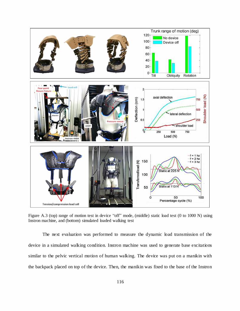
116
Figure A.3 (top) range of motion test in device “off” mode, (middle) static load test (0 to 1000 N) using Instron machine, and (bottom) simulated loaded walking test
The next evaluation was performed to measure the dynamic load transmission of the
device in a simulated walking condition. Instron machine was used to generate base excitations
similar to the pelvic vertical motion of human walking. The device was put on a manikin with
the backpack placed on top of the device. Then, the manikin was fixed to the base of the Instron

117
machine where the base excitation was applied, Figure A.3 (bottom). Two different backpack
loads were tested (113 N and 225 N), while Instron applied sinusoidal excitations to the base
with 2 cm of amplitude for three different frequencies (1,2 and 3 Hz) to simulate three different
walking speeds. Tension/compression load cell was mounted at the bottom of each column to
measure the transmitted force from the shoulder pads to the waist belt. Load cell data were
sampled at a frequency of 1 kHz, and post-processed with a low-pass filter (fourth order
Butterworth, Hz), averaged over cycle. About half of the applied load was statically
transferred from the shoulders to the waist through the columns consistently for two load
conditions and the base excitation indeed introduced dynamic load, in addition to the static load,
as can be seen by the curves of both load conditions. The peaks of such dynamic loads increased
with higher frequency and/or heavier mass. This implies that the magnitude of dynamic load in
human load carriage will increase as the body’s vertical acceleration increases. The results of
these evaluations validate the two functions of the device: load transmission capability and
accommodating a range of motion of torso.
118
Appendix B. Motorized Second Spine
A motorized Second Spine was designed that can actively modulate the vertical motion of a
backpack aiming to reduce its dynamic loads. This is realized by real-time coordination of motor
actuation in response to the waist vertical motion measured by an integrated motion sensor in
such a way that the backpack is kept inertially stationary. The performance of this de vice was
evaluated experimentally with an instrumented test-bed using an Instron machine, similar to
evaluation done on Second Spine. Results shows that the backpack motion can be made nearly
stationary with respect to the inertial frame (ground) by active modulation of motors by which
the dynamic force can be minimized.
A backpack supported by the Second Spine during walking can be modeled as a mass
undergoing harmonic excitation of the pelvis, . Since the connection between
the mass and the moving base is rigid, motion of backpack x(t) is the same as motion of the
pelvis, Figure B.1(a). The force transmitted to the pelvis R(t), therefore, is the sum of
gravitational force and the accelerative force induced by pelvis vertical motion during gait. If an
active component is imposed between the backpack and the waist belt, it can impose a motion to
the backpack relative to the pelvis which is denoted as z(t), Figure B.1(b). Such a motion can be
expressed as another sinusoidal function with controllable amplitude Z, frequency and phase
. Then, the motion of backpack is the superposition of two motions, pelvic motion y(t) and the
motor motion z(t). If the frequency of active component ( ) is preferably the same as that of
pelvis ( ) to avoid the beat phenomena, the transmitted force can be explicitly expressed, Figure
B.1(b). From this expression, it can be noticed that the amplitude of dynamic force is simply

119
√ [
]
[
] , which can be modulated by the amplitude ratio (
) and the phase
( ) between the two motions. Simulation of force transmissibility (the ratio of transmitted
force R between the Second Spine to the Motorized Second Spine) over different amplitude ratio
and phase showed that the force transmitted to the pelvis can be less than that of rigid
transmission (i.e., , below dashed line in Figure B.2) by modulating the phase of the
backpack motion with respect to the pelvis motion between and Force
transmissibility reaches its minima ( ) when [ ] [ ] , indicating the dynamic
force is minimized when z(t) has the same amplitude as that of pelvis vertical excitation with
phase (anti-phase). This simulation result provides the guideline for proper modulation of
motor needed to reduce the dynamic force component with respect to the vertical motion of the
pelvis.
Figure B.1 schematics of (a) passive Second Spine model and (b) motorized Second Spine model

120
Figure B.2 simulation results of force transmissibility ( ) of motorized second Spine with amplitude
ratio ( ) for different phase values ( )
Figure B.3 (left) CAD and physical model of linear actuator and motorized Second Spine, and hardware configuration; (right) schematic of motion controller implemented in motorized Second Spine
The design of the Motorized Second Spine is shown in Figure B.3(left), and the hardware
configuration is shown in Figure B.3(right). Implementation of motors, sensors, and real-time
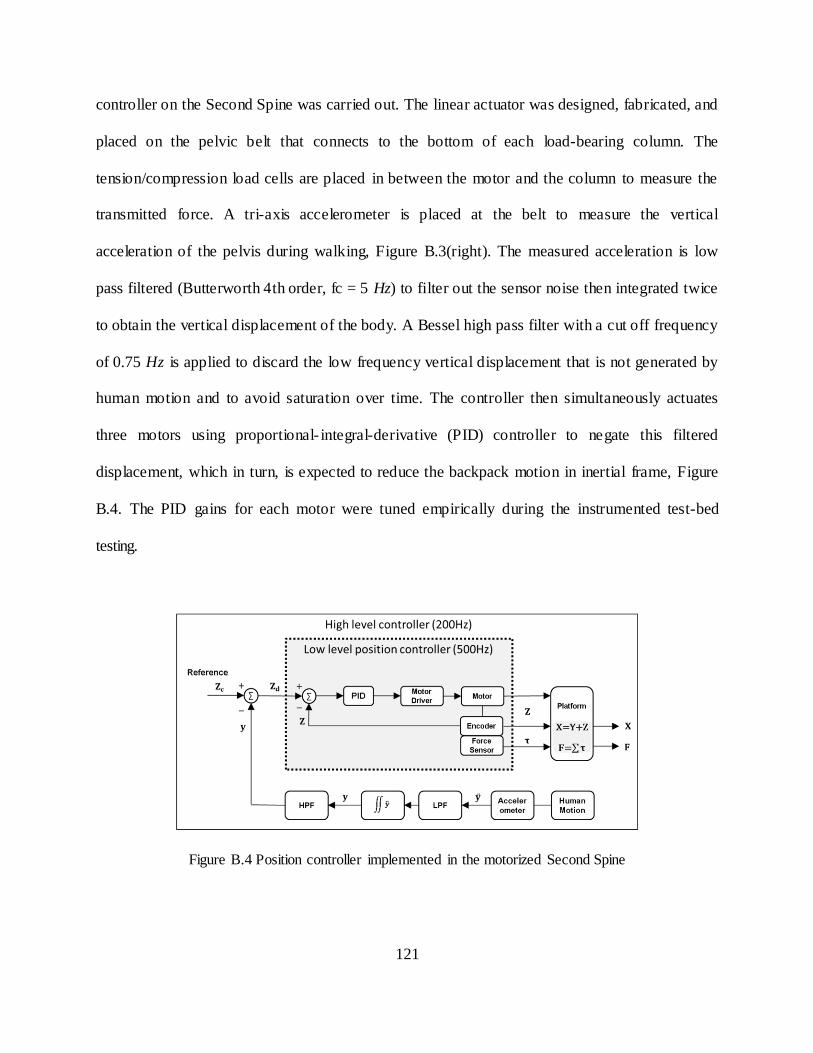
121
controller on the Second Spine was carried out. The linear actuator was designed, fabricated, and
placed on the pelvic belt that connects to the bottom of each load-bearing column. The
tension/compression load cells are placed in between the motor and the column to measure the
transmitted force. A tri-axis accelerometer is placed at the belt to measure the vertical
acceleration of the pelvis during walking, Figure B.3(right). The measured acceleration is low
pass filtered (Butterworth 4th order, fc = 5 Hz) to filter out the sensor noise then integrated twice
to obtain the vertical displacement of the body. A Bessel high pass filter with a cut off frequency
of 0.75 Hz is applied to discard the low frequency vertical displacement that is not generated by
human motion and to avoid saturation over time. The controller then simultaneously actuates
three motors using proportional- integral-derivative (PID) controller to negate this filtered
displacement, which in turn, is expected to reduce the backpack motion in inertial frame, Figure
B.4. The PID gains for each motor were tuned empirically during the instrumented test-bed
testing.
Figure B.4 Position controller implemented in the motorized Second Spine

122
The experiment evaluation on dynamic load compensation of the Motorized Second
Spine was carried out through simulated test-bed using Instron® machine. Two linear variable
differential transformers (LVDT) were mounted on Instron frame that simultaneously measure
the vertical displacement of the base and the mass (on shoulder pads) relative to inertial frame
Figure B.5. The device was mounted on the base and a 4.5kg mass was fixed on the top of the
shoulder pads. This particular setting was used to prevent any unmodeled disturbances during
experiment, such as friction between the device and the manikin or posterior load offset from a
use of a backpack. Sinusoidal base excitation of 2 Hz frequency and 0.5 cm amplitude was
simulated under three different configurations: motor-off ( ), motor-on with anti-phase
( ), motor-on with in-phase ( ). Figure B.6 plots the vertical displacement of the base
and the mass with respect to the inertial frame and the force transmitted to the belt.
Figure B.5. Experiment setup of the Motorized Second Spine
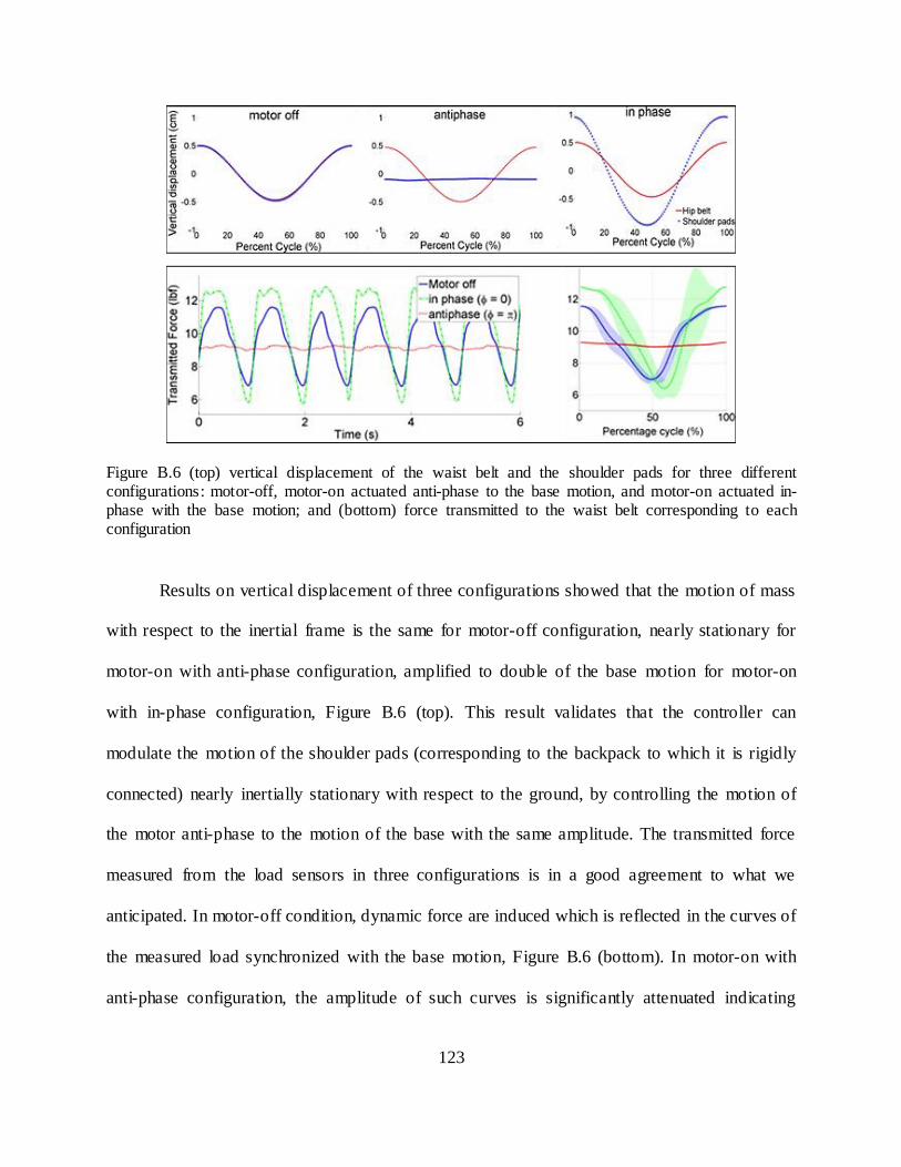
123
Figure B.6 (top) vertical displacement of the waist belt and the shoulder pads for three different configurations: motor-off, motor-on actuated anti-phase to the base motion, and motor-on actuated in-phase with the base motion; and (bottom) force transmitted to the waist belt corresponding to each configuration
Results on vertical displacement of three configurations showed that the motion of mass
with respect to the inertial frame is the same for motor-off configuration, nearly stationary for
motor-on with anti-phase configuration, amplified to double of the base motion for motor-on
with in-phase configuration, Figure B.6 (top). This result validates that the controller can
modulate the motion of the shoulder pads (corresponding to the backpack to which it is rigidly
connected) nearly inertially stationary with respect to the ground, by controlling the motion of
the motor anti-phase to the motion of the base with the same amplitude. The transmitted force
measured from the load sensors in three configurations is in a good agreement to what we
anticipated. In motor-off condition, dynamic force are induced which is reflected in the curves of
the measured load synchronized with the base motion, Figure B.6 (bottom). In motor-on with
anti-phase configuration, the amplitude of such curves is significantly attenuated indicating
124
reduction in dynamic forces transferred to the waist belt. In motor-on with in-phase configuration,
the amplitude of curves is even higher than the motor-off configuration indicating the dynamic
forces are increased due to the larger motion of mass than the motor-off configuration, which
consequently generates higher acceleration of mass. These results validates the concept of
dynamic load compensation by minimizing the motion of backpack with respect to the ground,
by use of motors in the Motorized Second Spine that can actively modulate the backpack motion
in response to the pelvic vertical motion.
125
Appendix C. Hardware specifications
Appendix C. 1 Hardware configurations of the Wearable upper Body Suit
The shoulder pads and load-bearing columns of the passive module were fabricated from a
carbon fiber composite to meet the required stiffness to support up to 90 kg load. The cable
actuator is comprised of a brushless EC motor, motor housing, and two Bowden cable mounts. It
is a 100 W motor equipped with 111:1 planetary gearhead and a 5 cm diameter winch is
connected to the motor shaft to reel in the cable. The nominal pulling force of the actuator is
371N @ 31cm/s and the maximum performance is 687N @ 13cm/s. The nominal current is
5.69A under 24V input. The motor is driven by a motor driver (ESCON 50/5, Maxon motor)
which regulates the current to the motor based on the controller command. The micro controller
(National Instrument, NI-myRio-1900) equipped with 667 Mhz dual core processor was used for
real-time control on the cable force. It receives the sensor signals as a feedback and outputs the
motor command based on the developed control law. It also has wi-fi communication through
which the host computer (laptop) monitors the system and controls the motor wirelessly.
Load sensors (LTH300, Futek) are integrated at the end of the passive and active cables
to measure the cable tension and strain gage amplifiers (CSG110, Futek) are paired with each
load sensor to transmit the amplified signal from the sensors to the controller. A tri-axis
accelerometer (ADXL335, Analog Devices, Norwood, MA) was attached to the belt and its axes
aligned to the trunk coordinate frame to measure the vertical accelerations of the pelvis, Figure
C.1 (d), from which the vertical velocity and displacement are also computed through integration.
A DB15 connector is used to bundle the electric wires from the passive module and is connected
to the active module via single 15-wire serial cable. This cable is used to power the sensors and

126
to accommodate the signal communications between passive and active module.
Connecting/disconnecting of this cable is easily done in seconds. Sensor data, motor command,
current draw, and other system parameters are logged in real time in a micro SD card at 200Hz
frequency. The stored data are later synchronized with external biomechanical and physiological
measurement devices (e.g., motion capture, electromyography, metabolic, etc.) for post-
processing. A 7-cell Lithum polymer battery (25.9V, 9Ah) was used as a main power source to
run all the electronics, except for the micro controller which uses a separate battery (7.4V 2Ah).
It can provide power to continuously run the system up to three hours while outputting 70 Watt
of assistive force into the passive module.

127
Figure C.1 (a) passive module and lifting mechanism, (b) active module, (c) cable actuator, and (d) accelerometer placed on the belt

128
Appendix C. 2 Hardware configurations of ROSE
Each ring of the ROSE is made using semi-rigid 0.25 cm fused deposition modeling (FDM) ABS,
separated by a 4 cm gap in the neutral position. Each segment has a series of holes along the
circumference at 10 increments. This allows flexibility in the placement of the actuator mounts
which attach to some of the holes. The actuator mounts were also made from FDM ABS. The
linear actuators are capable of a peak force of 50 N at speed of 16 mm/s with a 5 cm stroke
length (Firgelli, L16-50-35-12-P). At the base of each actuator, a load cell (Futek, LCM200) and
a conditioning board (Mantracourt, ICA6H) are mounted. Each actuator has a universal joint at
the base and a spherical joint at the top. The brace is lined with plastazote polyethylene foam for
comfort. The actuator’s position feedback and load cell voltage are multiplexed and sent to the
control board (National Instruments, sbRio-9626). The motors are driven at 12 V using a 1000Hz
PWM signal through a small driver (Toshiba, TB6612FNG). A 5-cell Lithum polymer battery
(18.5V, 2.2Ah) was used as a main power source to run all the electronics, except for the micro
controller which uses a separate battery (7.4V 2Ah). It is capable of translating and rotating in 3
dimensions (maximum ±2 cm in translation and ±10 degrees in rotations). It also can exert 3
dimensional forces and moments (±100 N in forces and ±10 Nm in moments).
Figure C.2 Portable electronics development (right) and fully portable Robotic Spine Exoskeleton prototype (left)

129
Appendix D. Parameterization, kinematics, and trajectory planning
of the ROSE
The Robotic Spine Exoskeleton consists of two parallel platforms connected in series. It has a
total of twelve active degrees-of-freedom controlled by twelve linear actuators. The architecture
of each parallel platform follows the kinematic structure of a 6-6 Stewart-Gough platform where
all the limbs share identical kinematic chains of UPS, Figure D.1.
Figure D.1 Schematics of the robotic spine brace and model and the limb model
The parameterization and dynamics will be presented for only the lower pa rallel platform, which
can also be extended to the top platform. Each limb connecting the fixed base to the moving
platform forms a kinematic loop, which can be expressed in the vector form as

130
with [ ] a position vector and a rotation matrix formed by three rotation
angles . is a vector with magnitude , along a unit vector along the leg.
[ ] is the vector of actuated joint coordinates and [ ]
is
the vector of moving platform motion variables.
[
]
is the rotation matrix relating the moving platform’s coordinate system to the base coordinate
system which is defined using pitch-roll-yaw angle rotations1 where and stand for the
sine and cosine of the argument, respectively. For inverse kinematic analysis, the moving
platform position and orientation are given and the problem is to solve for the joint
variables, [ ] . The length of each limb can be expressed as a norm of vector
[ ] [ ]
Hence, each limb length can be uniquely determined for given position and orientation of the
moving platform. For forward kinematic analysis, the joint variables are given and the problem
is to solve for of the moving platform. In this study, an iterative numerical solver is used with
screw axis representation of the rotation matrix [105, 106]. is redefined with screw
coordinates as
[ ]
in which and are obtained from rotation matrix as
1 pitch-roll-yaw angle is defined as first rotation about fixed x axis by ψ, followed by rotation about fixed
y axis by θ, followed by rotation about fixed z axis by ϕ

131
where represents the ith row and jth column component of . The seven equations to solve for
forward kinematics are
{
[ ] [ ]
The nonlinear least-square optimization routines were used to minimize
∑
. The
multiplicity of the solution is resolved by iteratively comparing the solution to the one obtained
from a previous step. If the error is within a prescribed threshold, that solution is chosen. The
Jacobian matrices are computed from velocity loop closures which are directly obtained by
differentiating the vector loop closure equation as follows
in which angular velocity of with respect to is
[
] [
] [
]
The velocity of the end effector (or twist) defined as [ ] is mapped
into the joint velocity vector by Jacobian as follows

132
[
]
From the principle of duality of kinematics and statics [107, 108], the forces and moments
applied at the end effector at static configuration are related to the joint forces required at the
actuators to maintain the equilibrium by the transpose of the Jacobian matrix, under the
assumption that the limb applies a force only along the limb axis. (The static wrench of the
moving platform can be also obtained using Jacobian and applying principle of virtual work,
assuming the limb applies a force only along the limb axis.)
[
]
[
]
[ ]
in which [ ] is the vector of forces experienced by the limbs (actuator force
vector), and [ ] is the end effector wrench.
The trajectory planner is implemented to generate the desired motion, which employs a
common trajectory generation method used in multivariab le space [109]. Such computed
trajectory describes the desired motion of moving platform for each degree-of- freedom in task
space. A fifth-order polynomial curve-fitting method is used to generate the desired motion
trajectories for all six pose variables that satisfy the six initial and final conditions: positions and

133
velocities at the initial and final times with continuities in acceleration, i.e.,
. Trajectory planning is implemented for
each degree-of-freedom independently in the following manner:
where X(t) is a position vector describing the positions and orientations of one ring with respect
to the other ring. Substituting the initial and final constraints and its derivat ives, six equations are
obtained in a matrix form.
[
]
[ ]
[
]
The determinant of left most matrix is ( ) thus this matrix is invertible provided ,
from which a unique solution for the polynomial coefficients can be determined. Such
coefficients can be further simplified if we consider the velocities and accelerations of all
degrees of freedom at initial and final times are equal to zero (rest), i.e.,
, such that
( ) ( )
( )
( ) ( )
( )
( ) ( ) ( )
134
Using above equations, task space motion trajectories are generated based on the given desired
initial and final pose of the platform.

135
Appendix E. In vitro spine stiffness measurement and its implication
There have been a number of studies conducted to experimentally investigate the stiffness of the
spinal motion segments, consisting of two vertebrae connected with intervertebral disk. Though
the stiffness of the spine motion segment may not have direct implication on the torso stiffness,
we hypothesize that there is a correlation between the stiffness of two bodies as one (spine) is a
sub-part of the other body (torso). Moreover, spine is presumably stiffer than any of other soft
tissues and muscles surrounding the spine, knowing the material properties and stiffness
characteristics of the torso would provide an insight into the spine stiffness since the spine may
have significant contribution to the overall characteristic of the torso stiffness.
The human spine has a very distinct feature compared to other skeletal structures in the
human body. It is comprised of a series of intervertebral joint (disk) which has all six degrees-of-
freedom capability and are interconnected by vertebrae, ligament, and muscles which all has
different stiffness characteristics. It also exhibits visco- and poro- elastic properties, which are
time, force, and pose dependent. Because of these properties it is hard to obtain the accurate
model of the spine mathematically. Therefore, the stiffness of the spine vertebrae was typically
obtained experimentally from a load-displacement measurement [100, 110, 111, 112, 113]. The
direct measurement of spinal motion segment stiffness matrix with all six degrees of freedom
taken into account has been only realized recently from the work presented in [114] by designing
a Stewart-platform type test machine that can displace the upper end of the spinal motion
segment to any specified 6-DOF position relative to the immobilized lower vertebra, Figure
E.1(left). The use of 6-DOF load cell attached to the upper end of the specimen made it possible
for the load-displacement measurement for all 6 DOF. Similar test-bed was developed by [102],

136
a dynamic, six-axis spine simulator that consists of independently controlled mechanism that
allows translation along and rotation about each of the three dimensional axis Figure E.1(right).
The stiffness coefficients are typically determined using a linear regression (least-squares
method) of the load-displacement measurements.
Figure E.1 (left) A “hexapod” spine testing machine developed by Stokes et al. [114], and (right) a dynamic six-axis spine simulator developed by Holsgrove et al. [102]
Each coefficient comprising the stiffness matrix can be interpreted as either the
translation or rotation about the coordinate axis in response to the single dimensional force
(either force or moment). Such a displacement response is not only a function of the magnitude
and direction of the applied force, but also the point of application as well. It has been a common
experimental setting to match the point of force (or d isplacement) application to the geometric
center of the cross section of the intervertebral disk such that the six-dimensional stiffness is
calculated at the vertebra center. The three-dimensional motion behavior of the human spine was
studied by static analyses with a geometric model of the spine and inter-vertebra discs [102, 103].
Goel have used the term “primary (or principal or major)” motion to indicate the two
displacement response (linear and angular displacement) of the spine in the plane of the applied
137
load while the other four motions are denoted as “secondary (or minor or coupled)” [111]. For
example, the primary motions subjected to the force along positive y axis (+Fy) are a translation
along positive y axis (+Ty) and rotation about x axis (-Rx) while the secondary motions are the
other four out-of-plane motions namely Tx, Tz, Ry, Rz. This behavior corresponds to the model
depicted in Figure E.2(a), wherein the spine is considered as a simplified truss structure that is
fixed at the center of the bottom vertebrae in all directions subjected to the external force at the
center of the top vertebrae. Later studies done by Gardner-Morse et al. [98] developed more
realistic model that consisting of a truss (vertebra) and a shear beam (motion segment) with a
rigid posterior offset . Such a model was used to identify several primary off-diagonal axis
terms of stiffness matrix which are inherited by the effects of added beam that is posteriorly
offset to the truss, e.g., anterior-posterior shear translation (Fy) and flexion/extension rotation
(Mx) due to the applied axial force (Fz). These spine models can be adopted to study the load-
displacement relationship of the torso due to the similarity in their structural composition:
muscles and soft tissues analogous to intervertebral disk as a truss structure, and the spine
analogous to motion segment (facet joints, ligaments, and tendons) as a beam structure, Figure E.
2(b).

138
Figure E.2 (a) spine vertebrae modeled as an equivalent truss/beam structure; (b) human torso model as an equivalent truss/beam structure analogous to (a); and (c) A 6x6 stiffness matrix
In earlier research on spine motion segment stiffness analyses, people have assumed that
the stiffness matrix is symmetric under the assumption of the conservation of energy and linear
elasticity [100, 110, 111, 112, 113, 114, 115, 116, 117]. Such an assumption reduces the number
of independent stiffness coefficient from 36 to 21. Some studies have also assumed the
symmetrical behavior about the sagittal plane at which the number of independent stiffness
coefficient is even more reduced from 21 to 12 [100, 99]. The nine terms that become zero under
this sagittal plane symmetry assumption are the forces associated with the displacements within
the sagittal plane, e.g., no lateral force ( ), no coronal lateral bending rotation
( ) associated with axial compression. Although a great amount of research has
been done to experimentally characterize the stiffness of the spinal segments, it is only recent
that the non-conservative nature of the spine motion segment was validated in vitro that have led
to obtain the non-symmetric stiffness matrix [97, 118, 102, 103]. The non-conservative nature of
the joint caused by the loss of energy due to poro- and visco- elastic effects of the disc, facet
joints, and ligaments was first considered in [118] where the stiffness matrix obtained was non-
symmetric. The stiffness matrices obtained in [97, 118, 102, 103] were also not symmetrical

139
about the diagonal stiffness, which was controversial to the symmetric assumption that had
governed in many earlier studies. The presence of non-conservative forces and moments cannot
ensure the symmetry of the stiffness matrix, which is well known in structural dynamics
(explained in next paragraph). Based on the previously established theory on spine force-motion
behavior applied onto the model considered in Figure E.2 (b), each stiffness matrix term can be
interpreted in a more physical sense.
Asymmetric property of stiffness matrix
In a linear elastic conservative system, the stiffness matrix is symmetric on the basis of
Maxwell’s Reciprocity Theorem2, which states that the displacement at point i due to a unit load
at another point j is equal to the displacement at j due to a unit load at i. Infinitesimal strain
theory also supports the symmetric property of the stiffness matrix, which states that the
constitutive properties of the material (stiffness) at each point of space can be assumed to be
unchanged by the deformation. Maxwell’s Reciprocity Theorem guarantees existence of
potential function for the conservative vector field such that
. Potential function is continuous and continuously differentiable function which
should obey under the Maxwell’s Reciprocity,
(
)
(
). Each element of stiffness
matrix has the form of
and using the above relation, we have , i.e., matrix
is symmetric. However, if the system is non-linear elastic and/or non-conservative, the
Maxwell’s Reciprocity Theorem is not applicable from which, consequently, the symmetric
property of the stiffness matrix is no longer guaranteed.
2 Maxwell’s Reciprocity Theorem states that the displacement at point i due to a unit load at another point
j is equal to the displacement at j due to a unit load at i.