web-based lighting automation system
TRANSCRIPT

CHAPTER 1
INTRODUCTION
The basic information, i.e., the various aspects as why this project was chosen
or why this project has become the need of the hour is discussed in this chapter.
1.1 OVERVIEW
The technology of modern times has grown tremendously. The light, which
was once a privilege to use, is now available to almost all the human beings of the
world. Lights are present everywhere from streets, stadiums, hospitals and each and
every home. This exploiting use of lights has also made it necessary to have an easier
and comfortable means to control and manipulate the lights.
1.2 BRIEF DESCRIPTION
The project is an industry standard project designed for factories, arenas,
hospitals etc. with the soul purpose of lighting automation, as it is very troublesome in
such huge places to control and manipulate a large number of lights. The project
targets at reducing the amount of work the user has to do in order to control and
manipulate the lighting systems.
Fig. 1.1 Lighting Automation System
SKNCOE, Department of Computer Engineering 2013-14

1.3 PROBLEM STATEMENT
The Project basically aims to build an end user software Lighting Automation
System and hardware interface for the same. The objectives of the project are to
communicate between the end user software ZigBee module at the same time send
data to other module using end user software.
1.4 APPLYING SOFTWARE ENGINEERING APPROACH
The software development lifecycle for this project comprises of
communication, planning, modeling, construction and deployment. The
communication was based on the requirement gathering of the project with the
company. In the planning stage we estimated the project cost using the COCOMO
model, which then later resulted in the scheduling, and tracking of project. In the
modeling stage the various modules and resources required for the project was done.
The construction part mainly consisted of coding and testing the application. We used
Unit Testing approach for testing. Lastly we deployed the application for a real life
scenario.
SKNCOE, Department of Computer Engineering 2013-14

CHAPTER 2
LITERATURE SURVEY
The literature survey includes the following:
a) Different Languages
The different languages to be used to implement the hardware as well as
software are discussed in this sub-topic. The survey helped us to understand what
languages to use for developing the application. The end user software part
incorporates VB for providing Graphic User Interface while MSDN (Microsoft
Developer Network) libraries are used for configuring the ports for the ZigBee
module. The database requirements are fulfilled with the use of MySQL software,
which is used for creating database and retrieving data from database. The language
used in MySQL is SQL.
b) Features of Languages
The GUI of the application has been developed using Microsoft Visual
Basic. The language VB is used to develop simple as well as complex Graphic User
Interface Applications. Visual Basic is a third-generation event driven programming
language and integrated development environment from Microsoft (IDE) for its COM
programming model first released in 1991.
Microsoft intended Visual Basic to be relatively easy to learn and use.
Visual Basic was derived from BASIC and enables the rapid application development
(RAD) graphical user interface (GUI) applications, access to databases using Data
Access Objects, Remote Data Object, or ActiveX Data Object, and creation of
ActiveX controls and objects.
Programming in VB is a combination of visually arranging components
or controls on forms, specifying attributes and actions for those components, and
writing additional lines of code for more functionality.
The database creation and retrieval of data from database is done using
MySQL. MySQL is an industry standard database management system used to deal
with databases. It is the world’s second most widely used open-source relational
database management system. It can be connected to the front end, i.e., the user end
SKNCOE, Department of Computer Engineering 2013-14

software and can be used to create databases and retrieve data as well. This need is
also quenched using SQL.
MySQL is a relational database management system (RDBMS), and ships
with no GUI tools to administer MySQL databases or manage data contained within
the databases. Users may use the included command line tools, or use MySQL "front-
ends", desktop software and web applications that create and manage MySQL
databases, build database structures, back up data, inspect status, and work with data
records. The libraries used for creating a connection between the application and
database is MySQL.Data and MySQL.Data.MySQLClient.
The Library used for hardware interfacing is MSDN. MSDN Library is a
library of official technical documentation content intended for developers developing
for Microsoft Windows. The MSDN Library documents the APIs that ship with
Microsoft products and also includes sample code, technical articles, and other
programming information. Specifically, the application uses MSDN libraries for
porting the hardware. These libraries will be embedded with the VB code for the
complete end user software application.
Each edition of MSDN Library can only be accessed with one help
viewer (Microsoft Document Explorer or other help viewer), which is integrated with
the then current single version or sometimes two versions of Visual Studio. In
addition, each new version of Visual Studio does not integrate with an earlier version
of MSDN. The library used for serial communication is System.io.ports, which is
important as far as setting up of the serial communication is concerned.
As far as the hardware for communication is concerned ZigBee devices
are used. ZigBee is a specification for a suite of high-level communication protocols
used to create personal area networks built from small, low-power digital radios.
ZigBee is based on an IEEE 802.15 standard. Though low-powered, ZigBee devices
can transmit data over long distances by passing data through intermediate devices to
reach more distant ones, creating a mesh network; i.e., a network with no centralized
control or high-power transmitter/receiver able to reach all of the networked devices
SKNCOE, Department of Computer Engineering 2013-14

CHAPTER 3
SOFTWARE REQUIREMENT SPECIFICATION
3.1 INTRODUCTION
The project concentrates on the use of end user software application as well as
the developed hardware to control and manipulate the lighting appliance at desired
locations.
3.1.1 Project Scope
The evolving technology of the modern age has made it necessary to control the
existing technologies efficiently and comfortably. The consumers expect the
development of products that are easy to use and are efficient and which can be bought
at the lowest possible cost from the industry. The daily difficulties related to lighting
automation faced by people ranging from industry professionals to modern day
housewives have inspired this project.
The project aims at controlling lighting appliances ranging from industries to
sub-urban homes using an end user application complemented by sophisticated
hardware, which is developed for the same. The project features controlling of lighting
appliances in groups as well as individually. The color and intensity of the lights can
also be changed. The quick access feature is provided by the predefined and user
definable presets. The other features include scheduling options, obtaining live
feedback, receiving notifications and maintenance pop-ups, bill estimation, power
consumption.
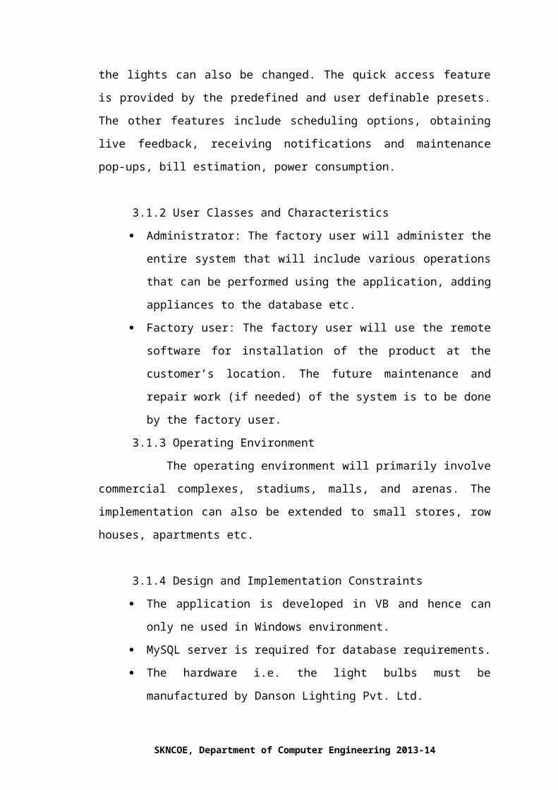
3.1.2 User Classes and Characteristics
Administrator: The factory user will administer the entire system that will
include various operations that can be performed using the application,
adding appliances to the database etc.
Factory user: The factory user will use the remote software for installation
of the product at the customer’s location. The future maintenance and repair
work (if needed) of the system is to be done by the factory user.
SKNCOE, Department of Computer Engineering 2013-14

3.1.3 Operating Environment
The operating environment will primarily involve commercial complexes,
stadiums, malls, and arenas. The implementation can also be extended to small stores,
row houses, apartments etc.
3.1.4 Design and Implementation Constraints
The application is developed in VB and hence can only ne used in Windows
environment.
MySQL server is required for database requirements.
The hardware i.e. the light bulbs must be manufactured by Danson Lighting
Pvt. Ltd.
The end user software is developed in VB.NET and requires MSDN
libraries for port configuration.
3.1.5 Assumptions and Dependencies
Although basic password authentication and role based security mechanisms
will be used to protect the user preference and data from unauthorized access;
functionality such as email notifications are assumed to be sufficiently protected under
the existing security policies. Redundant Database is setup as the role of backup
Database Server when primary database is failure.
3.2 SYSTEM FEATURES
SKNCOE, Department of Computer Engineering 2013-14

The system features of the project cover a vast control operation, which
incorporates the controls and manipulation techniques like grouping, scheduling, bill
estimation etc.
3.2.1 Grouping
The functionality of this feature is to group together the different lighting
appliances as the user wishes to group.
The user can group the lighting appliances and form different presets; also
the default presets will be provided that the user can configure as he wishes.
3.2.2 Color and Intensity
The user can change the color and intensity of the lighting appliances that
are grouped together or individual lighting appliance.
The user can also make a preset of his color and intensity preferences given
earlier.
3.2.3 Scheduling Options
The user can schedule the application to do a certain task at a particular date
and time.
Calendar and timer options are to be provided.
3.2.4 Zigbee Interface and Module
Zigbee Technology enables the system to be operated wirelessly.
Zigbee is efficient for communicating with other Zigbee modules and the
mac address of each ZigBee module can be used as an entry in the database
for each lighting appliance.
3.2.5 Live Feedback
This feature enables the estimation of current electricity consumption.
This also will help in calculation of estimated bill.
3.2.6 Maintenance Pop-ups
SKNCOE, Department of Computer Engineering 2013-14
This feature alerts the user for any possible maintenance issues that might
occur in the future
This feature will also alert the administrators so that they are ready with
new appliance if replacement is required.
3.2.7 Efficient Zigbee
Zigbee reduces our power consumption, as it is energy efficient.
Zigbee is also compact in design reduces our space requirement.
3.2.8 RGB Model
The RGB Model gives us a varied choice of colors, which the user can
have, in his place.
Hue saturation gives customer another versatile means to change colors.
3.3 EXTERNAL INTERFACES REQUIREMENT
3.3.1 User Interfaces
SKNCOE, Department of Computer Engineering 2013-14

We will be having user side software developed in VB.Net and MySQL at
the backend for maintaining the databases.
And also we will be using serial communication for communicating with
ZigBee modules, which will incorporate the use of MSDN libraries.
3.3.2 Hardware Interfaces
Hardware interfaces will mainly incorporate the ZigBee controller and the
ZigBee module. The other components of hardware include:
1. CPU usage
2. Memory usage
3. Server
4. End user machine
5. The ZigBee controller i.e. the ZigBee modem will be used at the end user
machine to communicate with all the ZigBee modules.
6. The ZigBee modules will be used to receive the data transmitted by the ZigBee
modem and control the lighting appliance accordingly.
3.3.3 Software Interfaces
Software interfaces will basically include a program to control the ZigBee
modem. The other software interfaces include:
MSDN libraries
Visual Basic
MySQL Database Management System
APACHE software server
3.3.4 Communication Interfaces
The basic communication interface will be the communication between the end
user system software and the ZigBee modem as well as ZigBee module. The other
interfacing that will be employed will be that of the web page with the end user
machine software.
3.4 NONFUNCTIONAL REQUIREMENT
The Non Functional requirements include the requirements that are not the
physical part of the system but control the system performance.
SKNCOE, Department of Computer Engineering 2013-14

3.4.1 Performance Requirements
The resource usage of the system will be restricted to the changes that are
made by the user. Overall the memory requirement will be very less.
If overload is caused at the software end restart the machine.
If the ZigBee modem or ZigBee module is not responding then the device
needs to be replaced.
3.4.2 Safety Requirements
The system will be completely safe for use, as no horrid appliances will be
installed.
The resources used by the hardware are very less and is very safe and
energy efficient.
3.4.3 Security Requirements
The application has two types of users, viz., Factory user and Administrator,
this in turn provides better security as the set of operations to be performed
are separated among these type of users.
The username and password will be encrypted for better security.
3.4.4 Software Quality Attributes
The libraries used for serial communication will strictly be MSDN libraries.
As for the application VB.Net is used for creating the GUI while MySQL is
used for all database operations. At the work station Apache that is a
industry leading software server will be used.
3.5 OTHER REQUIREMENTS
These are the other important requirements for the project which include
database requirements, legal requirements etc.
SKNCOE, Department of Computer Engineering 2013-14

3.5.1 Database Requirements
The database used will be user specific. As such no special requirements are
required.
The amount of data for a particular user will be moderate in size and as such
huge memory requirement is also not needed.
3.5.2 Legal Requirements
The hardware for the project is entirely the property of Danson Electronics
Pvt. Ltd. And cannot be sold or tampered with by any other authority other
than the company personnel.
The software used is freeware and comes bundled with the entire hardware.
Hence no legal requirements are necessary.
3.6 ANALYSIS MODELS
a) Data Flow Diagram
SKNCOE, Department of Computer Engineering 2013-14

Fig3.1 Data Flow Diagram
b) Class Diagram
SKNCOE, Department of Computer Engineering 2013-14

Fig3.2 Class Diagram
c) Entity-Relationship Diagram
SKNCOE, Department of Computer Engineering 2013-14

Fig3.3 Entity-Relationship Diagram
3.7 SYSTEM IMPLEMENTATION PLAN
SKNCOE, Department of Computer Engineering 2013-14
Mainly our project focuses on controlling lighting appliances using an end user
application coupled with ZigBee modules, i.e., hardware for communication.
The flow of the system i.e. the algorithm of the whole system will be as follows:
The whole system will be divided into 2 parts, which will consist of an
algorithm for each of the mentioned parts.
I. The end user application algorithm:
User logs into the application using the user id and the password provided.
The user later uses node discovery algorithm to find new ZigBee devices.
II. The on/off function:
The user has the option to switch on and off the appliance when he
chooses to switch on the light the value in the database will change to 1, which has a
default value 0.
III. Grouping:
In this the user has the option to group the appliances and set the group as
one of the presets provided or control that particular group. The group will be
added to the database and can be manipulated to apply on/off and other
functions.
IV. Calendar:
This option provides to schedule the different functions for an appliance or
a group of appliances, which will have a similar entry in the database as in grouping.
V. End user software:
This is the user side software, which will be installed at the end user’s
location where main interfacing with ZigBee module is to be done.
The software will also have all the functions, which the web page will
have to control the appliances. The software will use MSDN libraries for serial
communication. At the same time the GUI will be designed and provided using
VB.NET
SKNCOE, Department of Computer Engineering 2013-14
CHAPTER 4
SYSTEM DESIGN
4.1 SYSTEM ARCHITECTURE
For better understanding the system architecture has been divided into 3 parts
namely the web based part, the software part and the hardware part.
Fig4.1 System Architecture
The Software part:
In this the software will communicate with the hardware. It is somewhat like
an interface between the website and the hardware. The user commands need to
translate into ZigBee recognized codes. The GUI for the software will be developed
using Visual Basic (VB), which is also an industry leading standard. The basic coding
for the ZigBee will be done using breakthrough code. Obtaining values from the
micro-controller for each of the order given by the user through the software will be in
binary form, which then will be transferred to the database for further processing. The
login form will contain functionalities for user and admin login. After selecting the
type of login the respective form will be loaded which will provide the respective
functionalities depending on the type of login. The user can directly access the
functionalities like grouping, color and intensity options etc. The admin at the other
end has to select which user he wants to manipulate and then he has access to all the
functions that the user has and also the maintenance options.
SKNCOE, Department of Computer Engineering 2013-14

The admin part of the software will have a graphical image of a room in which he
an option to add appliances directly at the socket in the room as the image will show
the socket positions. This will give the admin a simpler and easy to add and remove
appliance in a particular working place. Similarly the user will also have an graphical
image to control the appliance rather than selecting the appliance from a list box or a
drop down box.
The software will be connected a database of which we will be using to store the
data of all the appliances similar in way we will be doing it in the web-based
application. The database will store the number of appliances, the working place data,
the MAC addresses of all the appliances for the controlling. It will also save the
current status of the appliance as well as the groups, presets and the calendar data into
it. The User’s profile will also be saved on the database and login details of user as
well as of the admin.
The Hardware part:
The hardware components will be basically incorporate the following:
ZigBee Transmitter
ZigBee Receiver
Appliances
Development Board
Micro-controller
The ZigBee works on RF (radio frequency) and hence can communicate wirelessly.
The ZigBee is a low cost, low power, wireless mesh network standard. The low cost
allows to be widely deployed in automation applications. Lower power usage allows
longer life. Mesh networking provides high reliability and more extensive range.
ZigBee builds upon the physical layer and media access control defined in IEEE
standard 802.15.4 for low rate WPAN’s. The specification goes on to the complete
standard by adding 4 main components namely, network layer, application layer,
ZigBee device objects and manufacturer defined application objects which allow
customization and favor total integration.
SKNCOE, Department of Computer Engineering 2013-14
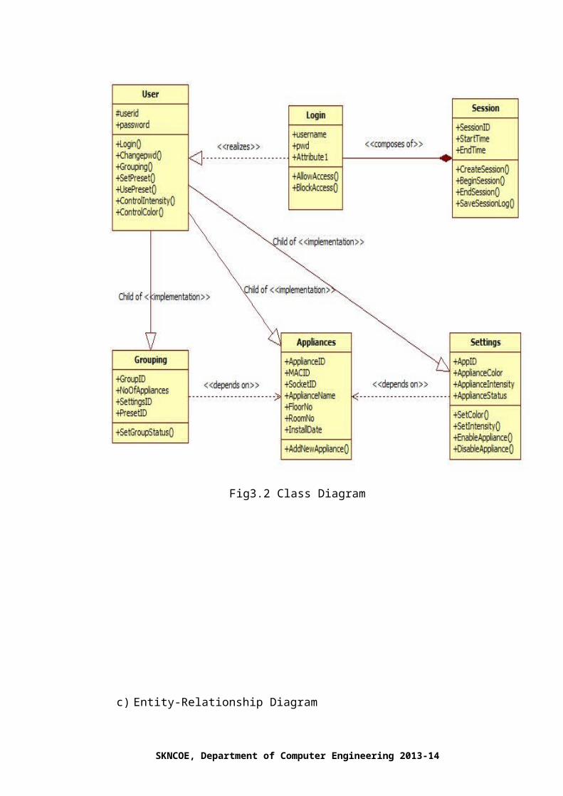
Fig4.2 ZigBee Protocol Stack
The user will send the information, which will include the changes he wants to
make using the web-based part and then this information will be stored at the server
from the where the web-based part is hosted. The server will further forward this
information to the end user machine where the software part will play its role. It will
act as in interface and for this information to the ZigBee controller in ZigBee
recognizable format. The ZigBee controller in turn will communicate with the ZigBee
modules. At this point of time the micro-controllers will come into effect, as they are
required to encode as well as decode the information sent and received. All this
communication will be bi-directional and will make it easier and better as well as
efficient.
4.2 UML DIAGRAMS
a) Use Case Diagram
SKNCOE, Department of Computer Engineering 2013-14

Fig4.3 Use-case Diagram
b) Sequence Diagram:
SKNCOE, Department of Computer Engineering 2013-14

Fig4.4 Sequence Diagram
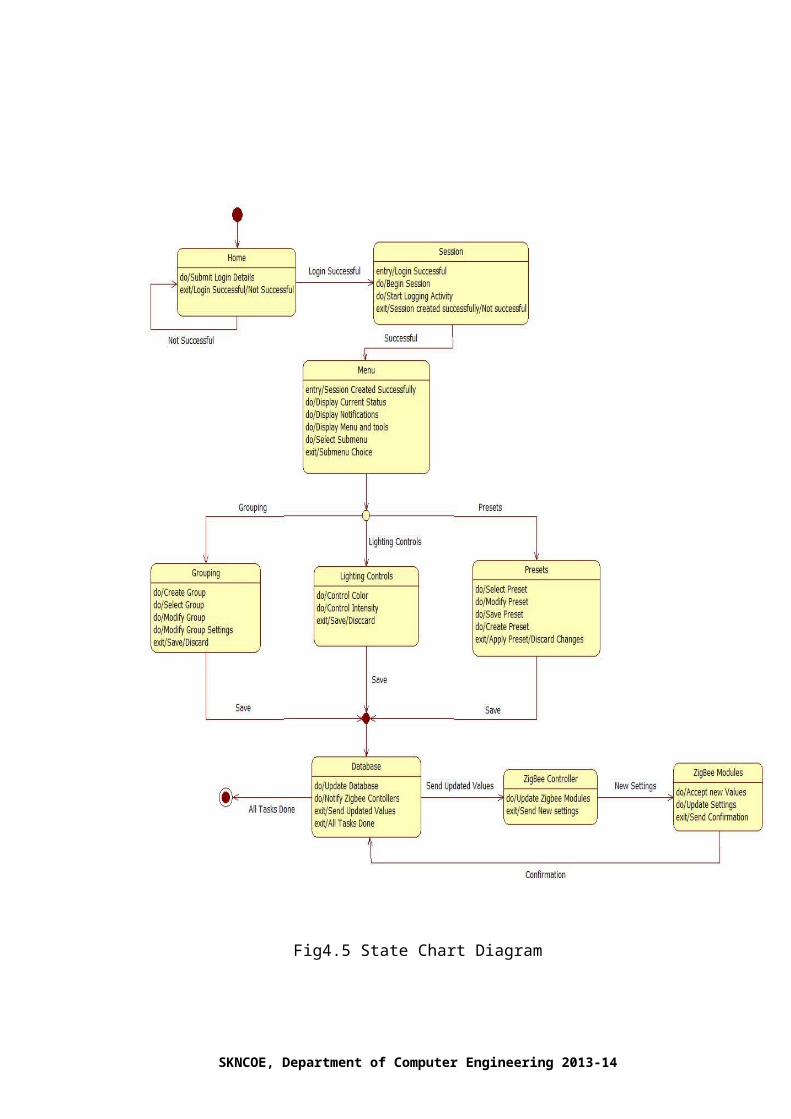
c) State Chart Diagram:
SKNCOE, Department of Computer Engineering 2013-14

Fig4.5 State Chart Diagram
d) Deployment Diagram:
SKNCOE, Department of Computer Engineering 2013-14

Fig4.6 Deployment Diagram
CHAPTER 5
SKNCOE, Department of Computer Engineering 2013-14

TECHNICAL SPECIFICATIONS
5.1 TECHNOLOGY DETAILS USED IN THE PROJECT
The project incorporates the use of different technologies including
Microsoft Visual Basic for developing the GUI, MySQL for database requirements,
and MSDN libraries for supporting serial communication, ZigBee appliances for the
actual communication.
V.1.1 Microsoft Visual Basic
Microsoft Visual Basic is an industry-leading standard for
developing various GUI based applications. It has been a pioneer in developing
applications, which require serial communication.
The project uses VB for developing the GUI by using its inbuilt
functionality supporting serial communication. The various forms created for the
application have been designed in VB as VB supports creation of a versatile modern
GUI. Microsoft Visual Basic also supports database connectivity, which is a core
aspect of the project. Microsoft Visual Basic provides a simple approach as far as
connectivity is concerned with the MySQL database.
V.1.2 MySQL
MySQL is basically used for all the functionalities regarding the
databases. MySQL complements the application by providing a back end for data
retrieval as well as for modifying the data.
The project uses MySQL for maintaining the required database.
The various functionalities of the application demand the retrieval of data from the
database for further usage, which is provided by MySQL. It is important to have a
secure database for the perfect functioning of the application, which is provided by
MySQL.
SKNCOE, Department of Computer Engineering 2013-14

V.1.3 MSDN Libraries
The MSDN libraries provide support and basic resources for
serial communication. Microsoft Visual Basic supports the use of MSDN libraries for
serial communication and hence their combination forms a strong means for
communication between the ZigBee appliances.
The project demands the use of ZigBee appliances for
communication between the different light bulbs. As discussed earlier the ZigBee
devices communicate serially and hence MSDN libraries are important.
V.1.4 ZigBee Appliances
ZigBee is a specification for a suite of high-level communication
protocols used to create personal area networks built from small, low-power digital
radios. ZigBee is based on IEEE 802.15 standard. ZigBee based appliances form a
mesh network and are used for serial communication.
The project aims at controlling and manipulating different
lighting appliances and hence requires hardware for communication. ZigBee being
cost effective and easier to implement is chosen for the same. ZigBee provides serial
communication and can be used with the GUI created in Microsoft Visual Basic.
SKNCOE, Department of Computer Engineering 2013-14

CHAPTER 6
PROJECT ESTIMATE, SCHEDULE AND TEAM STRUCTURE
6.1 TASKS AND MILESTONES
A task can be broken down into assignments, which should also have a defined
start and end date or a deadline for completion. One or more assignments on a task put
the task under execution. Tasks can be linked together to create dependencies.
T1. Selecting and Finalizing Group.
T2. Understanding and determining scope of the project.
T3. Literature survey.
T4. Hardware design.
T5. Hardware and interface Implementation.
T6. Finalize GUI.
T7. Test GUI and interface.
T8. Finalizing software structure.
T9. Software implementation.
T10. Debugging.
T11. Integration of software and hardware.
T12. System testing and analysis.
T13. Software Optimization.
T14. Project Finalization.
SKNCOE, Department of Computer Engineering 2013-14

6.1.1 Time Line Chart for Phase-I
15-Jul
27-Jul
8-Aug
20-Aug
1-Sep
13-Sep
25-Sep
7-Oct
19-Oct
31-Oct
12-Nov
24-Nov
6-Dec
18-Dec
30-Dec
0
10
20
30
40
50
60
70
80
Desired % completionActual % Completion
T1. Selection and Finalizing Group.
T2. Understanding and determining scope of the project.
T3. Literature survey.
T4. Hardware design.
T5. Hardware and interface Implementation.
T6. Finalize GUI.
T7. Test GUI and interface.
T8. Finalizing software structure.
T9. Software implementation.
T10. Debugging.
Fig. 6.1 Time Line Chart for Phase-I
SKNCOE, Department of Computer Engineering 2013-14
Indicate tasks
Chart no. 6.1 Phase-I Timeline

6.1.2 Time Line Chart for Phase-II
Following is the time line chart for the Phase II of the project-
6-Jan
10-Jan
14-Jan
18-Jan
22-Jan
26-Jan
30-Jan
3-Feb
7-Feb
11-Feb
15-Feb
19-Feb
0
20
40
60
80
100
120
Desired % CompletionActual % Completion
T10. Debugging.
T11. Integration of software and hardware.
T12. System testing and analysis.
T13. Software Optimization.
T14. Project Finalization.
Fig. 6.2 Time Line Chart for Phase-II
SKNCOE, Department of Computer Engineering 2013-14
Indicate tasks
Chart no. 6.2 Phase II Timeline

6.2 COSTS AND EFFORT ESTIMATION
The Constructive Cost Model (COCOMO) is generally used estimation
measures of cost, project duration, man power etc.
Like all estimation model, the COCOMO model requires sizing information. This
information can be specified in the form of
Object Point (OP)
Function Point (FP)
Lines of code (KLOC)
For our project, we use the sizing information in the form of Lines of source code.
Total Lines of source code in our project KLOC =2.5K(approx.)
Cost of each person per month Cp= 2750/-(Per Person-month)
Equations
Equation for calculation of effort in person-month for the COCOMO model is:
E=a*(KLOC)^b
Where,
a=3.6
b=1.2 for semi detached projects
E=Effort in person-months
D= a*(E)^b
Where,
a=2.5
b=0.32 for a semi detached projects
D=Duration of project in months.
Semi-Detached Projects:
A project of moderate size and complexity where teams with mixed experience
levels must meet a mix of rigid and less than rigid requirements.
Equation for calculation of Number of people required for completion of
project, using the COCOMO model is
N= E/D
Where,
SKNCOE, Department of Computer Engineering 2013-14
N=Number of people required
E=Efforts in person-month
D=Duration of project in month
Equation for calculation of cost of project, using the COCOMO model is:
C= D *Cp
Where,
C=Cost of project
D=Duration of project in months
Cp= Cost incurred per person-month
Efforts:
E= 3.6(2.5)^1.2
E=13.966person-months
Total of 13.966 person-months are required to complete the project
Successfully
Duration of project:
D=2.5*(E)^0.32
D=3.11months
Number of people required for project:
N=13.966/3.11
N=4.49
N= 4 people
Therefore 4 people are required to complete the project
Cost of project:
C= 3.11* 6,000
C=18,660/-
Therefore cost of project is approx. Rs.18, 660/-
CHAPTER 7
SOFTWARE IMPLMENTATION
SKNCOE, Department of Computer Engineering 2013-14

7.1 INTRODUCTION
The project aims at manipulating and controlling the various lighting devices
using the application developed in Visual Basic, which directs the ZigBee modules to
communicate among themselves. The software incorporates various industry standard
technologies like Microsoft Visual Basic and MySQL databases. The GUI has been
developed in Visual Basic and is easy to use as far as the user is concerned. The
setting up of the entire system is sophisticated and hence is done by the factory user,
i.e., the company technician. The GUI provides various options like adding an
appliance, grouping the appliances, applying various changes to a group of appliances
or to a single appliance. The GUI also provides various options like Grid View the
plan of the target floor/room, which can be provided by the user. MySQL maintains
the entire database that is demanded by the application. MySQL is the most efficient
option as it provides easy connectivity with Visual Basic and is good at maintaining
and manipulating databases.
The project is a combination of software and hardware and hence it is
important that the connection between the two should be stable. In order to provide a
secure serial communication MSDN libraries are used which are supported by Visual
Basic. The MSDN library is used to create serial port objects for serial
communication. The MSDN libraries are used to set the baud rate, to set the data bits,
to set the parity etc. The functions of serial port objects like open, write and read are
used to open a serial port connection, to write using the established connection and to
read using the established connection respectively.
7.2 DATABASES
SKNCOE, Department of Computer Engineering 2013-14

The databases for the application are maintained using Oracle’s MySQL. The
databases for the application maintain a number of records required by the application
including various tables like devices table, plans table, groups table etc. The following
figures show the various tables that are required by the application.
Fig. 7.1 Devices Table
The above figure depicts the devices table, which contains the various
attributes of a device including the appliance id, appliance name, status, group id etc.
Fig. 7.2 Groups table
The above table depicts the group table, which has attributes like group id, group
name and group status.
SKNCOE, Department of Computer Engineering 2013-14

Fig. 7.3 Event Scheduler Table
The above figure depicts the event-scheduling table, which has attributes like
event id (eid), event name (ename) etc.
Fig. 7.4 Plans Table
The above table depicts the plans table, which has attributes like room id, name
and path.
Fig. 7.5 Power Table
The above table depicts the power table, which has attributes like date and
value.
SKNCOE, Department of Computer Engineering 2013-14

Fig 7.6 Unallocated Appliance Table
The above table depicts the unallocated appliance table, which keeps track of
the unallocated appliances.
Fig. 7.7 User Accounts Table
The above table depicts the user accounts table, which keeps track of the user
accounts using the attributes username, password, type (i.e. Administrator or Factory
User) and id.
7.3 IMPORTANT MODULES AND ALGORITHMS
SKNCOE, Department of Computer Engineering 2013-14

The important modules of this project include transmission and reception of
data between the different ZigBee devices, Discovering new ZigBee nodes etc.
Initially the applications provides to options viz., INITIALIZE and REFRESH. The
INITIALIZE option clears the databse so that discovering all the ZigBee nodes can
create a new database. The REFRESH option does not clear the database but finds new
ZigBee nodes (if found any).
The important algorithms in the project have been discussed below,
a) Discovering new ZigBee Devices:
1. Giving an input +++ to the ZigBee enables the ZigBee’s command mode. To
this the ZigBee sends a reply message OK.
2. The next command given to the ZigBee is ATND when it is in command
mode. The ZigBee returns the values of SH (Source’s Higher Address) and SL
(Source’s Lower Address).
3. After Retrieving the values of SH and SL we check if the same addresses are
present in the database
4. If such values is present then we ignore this node and if it is not present then
we place the newly acquired address in the table Unallocated Appliances in the
database.
5. All the unallocated appliances are displayed to the user along with their
respective MAC addresses.
6. The user can add these MAC addresses to the database and add the device.
Also the user has to enter various attributes of the device like appliance name
and plan.
7. If the plan is new then user has to enter new layout or else if the layout is
already present then user can select it from a list of given layouts.
8. Once the devices are added the user can further go on to control and
manipulate them.
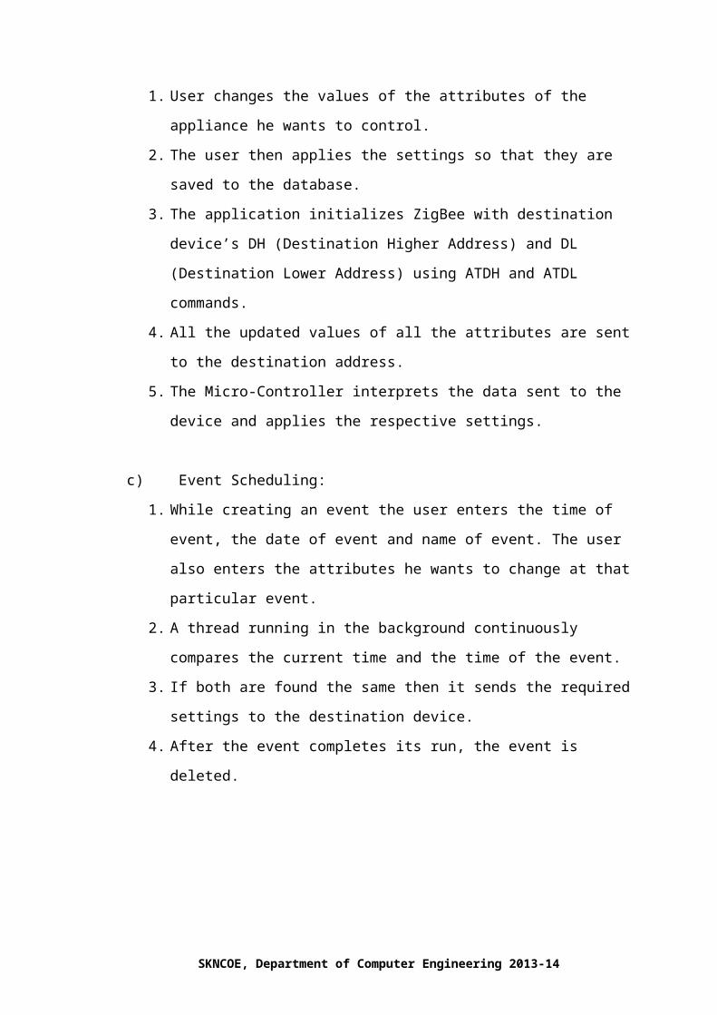
b) Applying settings:
SKNCOE, Department of Computer Engineering 2013-14

1. User changes the values of the attributes of the appliance he wants to control.
2. The user then applies the settings so that they are saved to the database.
3. The application initializes ZigBee with destination device’s DH (Destination
Higher Address) and DL (Destination Lower Address) using ATDH and
ATDL commands.
4. All the updated values of all the attributes are sent to the destination address.
5. The Micro-Controller interprets the data sent to the device and applies the
respective settings.
c) Event Scheduling:
1. While creating an event the user enters the time of event, the date of event and
name of event. The user also enters the attributes he wants to change at that
particular event.
2. A thread running in the background continuously compares the current time
and the time of the event.
3. If both are found the same then it sends the required settings to the destination
device.
4. After the event completes its run, the event is deleted.
7.4 BUISNESS LOGIC AND ARCHITECTURE
SKNCOE, Department of Computer Engineering 2013-14

The following figure depicts the Business Logic of the project. The
Presentation layer is nothing but the user interfaces i.e. the GUI. The Logic layer
evaluates different values, co-ordinates processes, makes logical decisions etc. The
data layer constitutes the data storage and the database.
Fig. 7.8 Business Logic
SKNCOE, Department of Computer Engineering 2013-14

CHAPTER 8
SOFTWARE TESTING
8.1 INTRODUCTION
Software Testing helps investigate the bugs (if any), the quality of product, the
service under test etc. The lighting automation requires least number of bugs and
crashes. The database of should be without redundancy and should be updated
frequently. All these problems make it necessary to perform testing as far as software
is concerned.
Designing different test cases taking into consideration certain scenarios where
the software application or the database may fail or crash does the software testing. It
is necessary to design the test cases properly i.e. the test cases should be accurate.
Consider a case where we have to make certain changes to an appliance.
Suppose we have to change the color, intensity and group number of an appliance.
Here we make changes to the above-mentioned attributes of the appliance in the
manage appliance tab. After making the changes we click the APPLY button to
confirm the changes made. We have to check whether the changes have been made in
the database also i.e. whether the values for the above-mentioned attributes for that
particular appliance have been made. Checking the database entries and finding if any
changes have been made to those specific attributes of the particular appliance selected
can do this. If the changes have been made then we get a negative test result and if we
no changes are made then the result is positive. It is desirable to get a negative test
result.
The query for the above-mentioned test case is written as follows:
Select * from devices;
The devices table maintains the values of color, intensity, group number etc.
Check if changes are made to these values if yes then test case fails which is desirable
SKNCOE, Department of Computer Engineering 2013-14

but if the result is a hit i.e. if the test case is successful then we have to find the error
because of which database is not updated.
8.2 TEST CASES
The various test cases designed for the application are listed here. Mostly Unit
Testing has been done which has given the best possible results.
Introduction:
Software testing is a critical element of software quality assurance and
represents the ultimate review of specification, design and coding. Testing presents an
interesting of a system using various test data. Preparation of the test data plays a vital
role in the system testing. After preparation the test data, the system under study is
tested those test data. Errors were found and corrected by using the following testing
steps and corrections are recorded for future references. Thus, series of testing is
performed on the system before it is already for implementation.
The development of software systems involves a series of production activities
where opportunities for injection of human errors are enormous. Errors may begin to
occur at the very inception of the process where the objectives may be erroneously or
imperfectly specified as well as in later design and development stages. Because of
human in ability to perform and communicate with perfection, software development
is followed by assurance activities. Quality assurance is the review of software
products and related documentation for completeness, correctness, reliability and
maintainability. And of course it includes assurances that the system meets the
specification and the requirements for its intended use and performance. The various
levels of quality assurance are described in the following sub sections.
System Testing
Software testing is a critical element of software quality assurance and
represents the ultimate review of specifications, design and coding. The testing phase
SKNCOE, Department of Computer Engineering 2013-14

involves the testing of system using various test data; Preparation of test data plays a
vital role in the system testing. After preparation the test data, the system under study
is tested.
Those test data, errors were found and corrected by following testing steps and
corrections are recorded for future references. Thus a series testing is performed on the
system before it is ready for implementation.
The various types of testing on the system are:
● Unit testing
● Integrated testing
● Validation testing
● Output testing
● User acceptance testing
Unit testing
Unit testing focuses on verification effort on the smallest unit of software
design module. Using the unit test plans. Prepared in the design phase of the system as
a guide, important control paths are tested to uncover errors within the boundary of the
modules. The interfaces of each of the modules under consideration are also tested.
Boundary conditions were checked. All independent paths were exercised to ensure
that all statements in the module are executed at least once and all error-handling paths
were tested. Each unit was thoroughly tested to check if it might fall in any possible
situation. This testing was carried out during the programming itself. At the end of this
testing phase, each unit was found to be working satisfactorily, as regarded to the
expected out from the module.
Integration Testing
Data can be across an interface one module can have an adverse effect on
another’s sub function, when combined may not produce the desired major function;
global data structures can present problems. Integration testing is a symmetric
technique for constructing tests to uncover errors associated with the interface. All
modules are combined in this testing step. Then the entire program was tested as a
whole.
SKNCOE, Department of Computer Engineering 2013-14

Validation Testing
At the culmination of integration testing, software is completely assembled as a
package. Interfacing errors have been uncovered and corrected and final series of
software test-validation testing begins. Validation testing can be defined in many
ways, but a simple definition is that validation succeeds when the software functions
in manner that is reasonably expected by the consumer. Software validation is
achieved through a series of black box tests that demonstrate conformity with
requirement. After validation test has been conducted, one of two conditions exists.
● The function or performance characteristics confirm to specification that are
accepted.
● A validation from specification is uncovered and a deficiency created.
Deviation or errors discovered at this step in this project is corrected prior to
completion of the project with the help of user by negotiating to establish a method for
resolving deficiencies. Thus the proposed system under consideration has been tested
by using validation testing and found to be working satisfactorily.
Output Testing
After performing the validation testing, the next step is output testing of the
proposed system, since a system is useful if it does not produce the required output in
the specific format required by them tests the output generator displayed on the system
under consideration. Here the output is considered in two ways: - one is onscreen and
the other is printed format. The output format on the screen is found to be correct as
the format was designed in the system design phase according to the user needs. As far
as hardcopies are considered it goes in terms with the user requirement. Hence output
testing does not result any correction in the system.
SKNCOE, Department of Computer Engineering 2013-14

User Acceptance Testing
User acceptance of the system is a key factor for success of any system. The
system under consideration is tested for user acceptance by constantly keeping in
touch with prospective system and user at the time of developing and making changes
whenever required.
TEST RESULT: UNIT TESTING
LOGIN FORM:
Test Result Excepted ResultTest CaseSL.No
SuccessfulSoftware should display
the initializing window
for nodes.
Enter valid name
and password &
click on login
button
1
SuccessfulSoftware should display
the ports lists and able
to select the proper port.
Enter valid name
and password &
click on
configure COM
ports button.
2
Table no. 8.1 Test Cases-Login Form
SKNCOE, Department of Computer Engineering 2013-14

Fig. 8.1 Login Form
The Fig. 8.1 depicts the Login window of the application, which is used to add
appliances.
ADMINISTRATOR FORM:
Test Result Excepted ResultTest CaseSL.No
Successful
The window should show the
layout of the floor plan allocated to
the admin and allow him to modify
the basic controls of the appliances
and no other privileges should be
active.
On the entering
the admin
window after
admin login.
1
SuccessfulThis changes the status of the
appliance.
On the Click of
STATUS Button
2.
SuccessfulThe modified color values using
the track bars should show
respective color change in the
preview box.
On the Changing
the value of
COLOR (RGB)
track bars.
3.
SuccessfulThe track bar should change its
value properly and show the
changes in the intensity text field.
On the Changing
the value of
INTENSITY
track bars.
4.
SuccessfulThe values modified should get
saved and send them to respective
appliance.
On the Click of
APPLY Button
5.
SKNCOE, Department of Computer Engineering 2013-14

SuccessfulThe values should not get modify
and no change should be observed
and should stay on same form.
On the click of
CANCEL
button.
6.
Table no. 8.2 Test Cases-Administrator Form
INTIALIZE FORM:
Test Result Excepted ResultTest CaseSL.No
Successful
This button click
should show all the
new nodes present in
the periphery with
their MAC addresses
displayed and give
an option to add
them as an
appliance.
On the click of
INITIALIZE button.
1
SuccessfulThis button click
should all the
unallocated MAC
addresses in the
database and should
display if any new
nodes are present in
the periphery.
On the Click of
REFRESH Button
2.
SuccessfulAfter selecting any
one of the MAC
address from the
above list it should
allow it to add it and
store in the database
On the Click of
ADD Button
3.
SKNCOE, Department of Computer Engineering 2013-14

with entering details
in the new ADD
APPLIANCE form.
Table no. 8.3 Test Cases-Initialize Form
Fig. 8.2 Discover Appliance Window
The Fig. 8.2 depicts the discover appliance window which is used to discover
new appliances in order to add to the database.
SKNCOE, Department of Computer Engineering 2013-14

Fig. 8.3 Add Appliance Window
The Fig. 8.3 depicts the add appliance window which is used to add an
appliance using the application.
Fig. 8.4 Database Entries
The Fig. 8.4 depicts the database after an appliance is added and it also depicts
that the database has been updated as soon as the appliance is added which means the
test case gave a negative hit.
SKNCOE, Department of Computer Engineering 2013-14

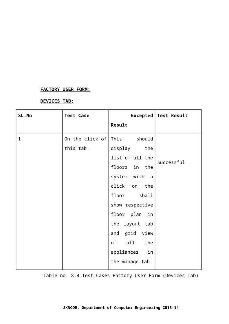
FACTORY USER FORM:
DEVICES TAB:
Test Result Excepted ResultTest CaseSL.No
Successful
This should display
the list of all the floors
in the system with a
click on the floor shall
show respective floor
plan in the layout tab
and grid view of all
the appliances in the
manage tab.
On the click of this
tab.
1
Table no. 8.4 Test Cases-Factory User Form (Devices Tab)
SKNCOE, Department of Computer Engineering 2013-14
. Fig. 8.4 Factory User Window
SKNCOE, Department of Computer Engineering 2013-14

The Fig. 8.5 depicts the factory user window, which provides all the
functionalities that can be used to control or manipulate the appliances.
EVENTS TAB:
Test Result Excepted ResultTest CaseSL. No
Successful
This will list all the
events scheduled and
then after clicking will
show the event details
in the corresponding
tab besides.
On the click of this
tab.
1
SuccessfulIt displays the add
event form and enter
the event details.
On the click of Add
Event button.
2
SuccessfulIt applies all the event
details to the
appliance and saves
them to database thus
On the click of Apply
button
3
SKNCOE, Department of Computer Engineering 2013-14

sending values.
Table no. 8.5 Test Cases-Factory User Form (Events Tab)
MANAGE TAB:
Test Result Excepted ResultTest CaseSL.No
Successful
This will list the entire
appliance in the floor
with its appid, name and
addresses.
On the click of this
tab.
1
SuccessfulIt shall display the floor
layout.
On click of layout
button.
2
SuccessfulSelecting the appliance
from the list of grid view
and then it gets added
into the group selected
from the combo box.
On click of Add to
Group button.
3
SuccessfulSelecting the appliance On click of Remove 4
SKNCOE, Department of Computer Engineering 2013-14

from the list in grid view
and then removing it
from the group in which
it exists.
from group.
SuccessfulThis shall delete the
appliance from the grid
view list itself and
database too.
On the click of Delete
Appliance button
5
SuccessfulIt will change the
controls apply to the
database and send
values.
Control panel6
Table no. 8.6 Test Cases-Factory User Form (Manage Tab)
LAYOUT TAB:
Test Result Excepted ResultTest CaseSL.No
SuccessfulThis should display
the layout of the
particular floor
chosen.
On the click of this
tab.
1
SuccessfulThis should pop a
form for changing
the particular
position of the
appliance within the
floor.
On the click of
Change of position
button.
2
SuccessfulThis shall delete the
appliance from the
layout itself and
On the click of
Delete Appliance
3
SKNCOE, Department of Computer Engineering 2013-14

database too.button
Table no. 8.7 Test Cases-Factory User Form (Layout Tab)
Fig. 8.5 Layout Window
The Fig. 8.6 depicts the layout window, which is used to display the layout and
ask the user to input the position of the light.
SKNCOE, Department of Computer Engineering 2013-14

CHAPTER 9
RESULTS
SKNCOE, Department of Computer Engineering 2013-14
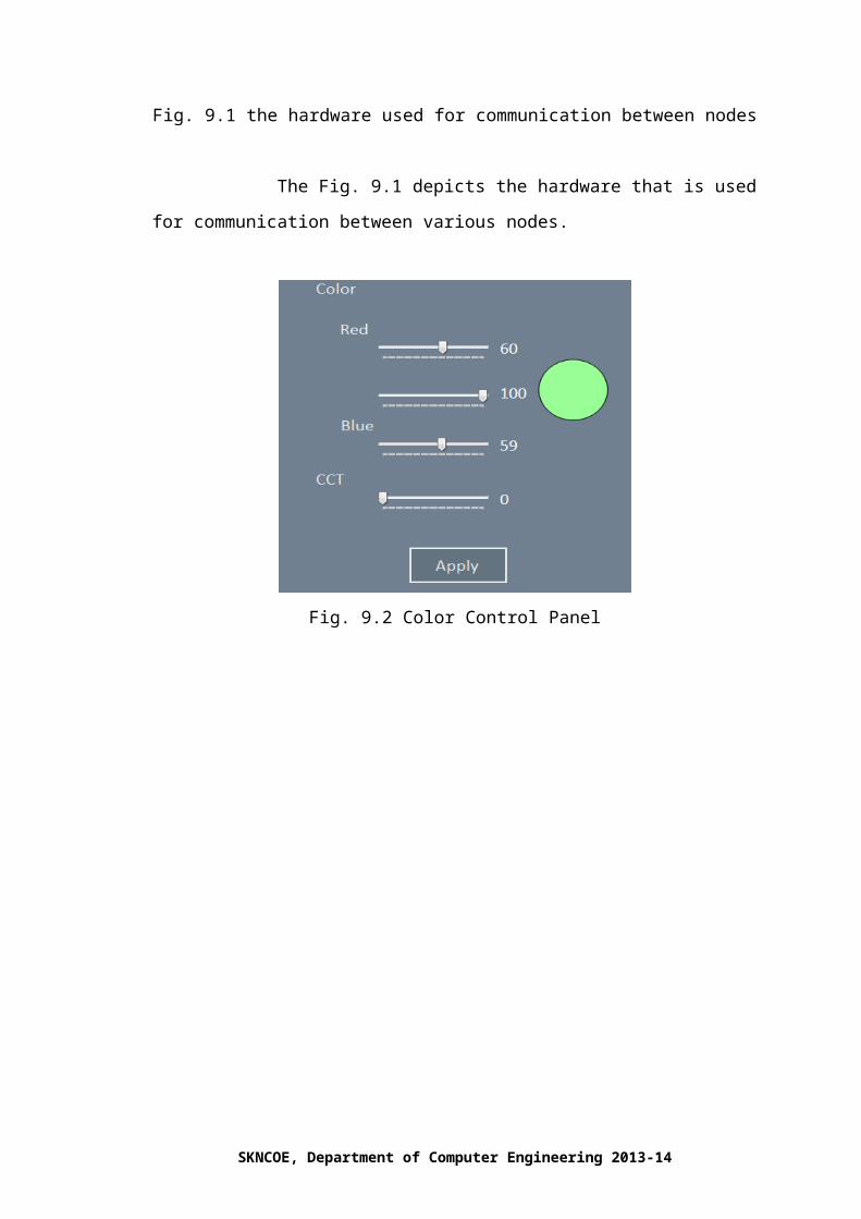
Fig. 9.1 the hardware used for communication between nodes
The Fig. 9.1 depicts the hardware that is used for communication between
various nodes.
SKNCOE, Department of Computer Engineering 2013-14

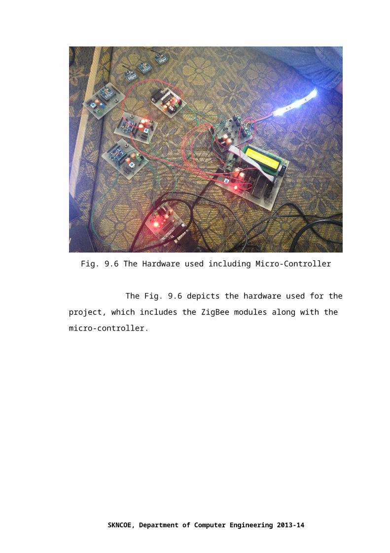
Fig. 9.2 Color Control Panel
Fig. 9.3 RGB Values with Output
The Fig. 9.2 depicts the control panel for selecting a desired color while fig.
9.3 depicts the corresponding output with corresponding RGB values.
SKNCOE, Department of Computer Engineering 2013-14

Fig. 9.4 Color Control Panel
Fig. 9.5 RGB values with Output
The Fig. 9.4 depicts the control panel for selecting a color and fig. 9.5 depicts
the corresponding output with corresponding RGB values.
SKNCOE, Department of Computer Engineering 2013-14

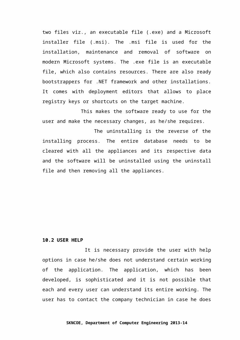
Fig. 9.6 The Hardware used including Micro-Controller
The Fig. 9.6 depicts the hardware used for the project, which includes the
ZigBee modules along with the micro-controller.
SKNCOE, Department of Computer Engineering 2013-14

CHAPTER 10
DEPLOYMENT AND MAINTAINENCE
10.1 INSTALLATION AND UNINSTALLATION
The installation of lighting automation software should be easy as the most
primitive users can use this application. The deployment of this project begins with the
installing of all the appliances at the location where this is to be deployed and is to be
done by technician. The main work of the technician will be to setup all the appliances
and then installing the software and then configuring the ZigBee based appliances with
the help of software. The software needs to be installed on the local machine with the
help of its installer file, which will consist of the main software and its related
database, which is a MySQL database. The local machine needs to have an Apache
server and a MySQL database management system, which runs on Apache and
supports the software to store the values. Then the technician will login into the
software with login details of user provided by the company, which then helps to
configure the appliances and then check if all the appliances are setup and are
working. The Visual Basic code when built creates two files viz., an executable file
(.exe) and a Microsoft installer file (.msi). The .msi file is used for the installation,
maintenance and removal of software on modern Microsoft systems. The .exe file is an
executable file, which also contains resources. There are also ready bootstrappers
for .NET framework and other installations. It comes with deployment editors that
allows to place registry keys or shortcuts on the target machine.
This makes the software ready to use for the user and make the necessary
changes, as he/she requires.
The uninstalling is the reverse of the installing process. The entire database
needs to be cleared with all the appliances and its respective data and the software will
be uninstalled using the uninstall file and then removing all the appliances.
SKNCOE, Department of Computer Engineering 2013-14

10.2 USER HELP
It is necessary provide the user with help options in case he/she does not
understand certain working of the application. The application, which has been
developed, is sophisticated and it is not possible that each and every user can
understand its entire working. The user has to contact the company technician in case
he does not understand the user faces anything or some issue. The company is
responsible solely for maintaining the appliances and the software as both the software
and hardware has to be checked in case the user encounters an issue.
SKNCOE, Department of Computer Engineering 2013-14

CAHPTER 11
CONCLUSION AND FUTURE SCOPE
This project has shown the ability of technology to help between end user
lighting automation system and hardware interface for the same. This project has also
investigated how the use of the technology used can benefit sub-urban homes,
industrial areas and commercial fields.
This project has also shown us that low-cost technology like ZigBee can be
used for communication with efficiency. This project has given us a possibility of a
comfortable and efficient means of controlling huge number of lights with ease.
This type of automation system is mainly used for home automation systems.
Its future scope also involves controlling robo-arms or octo-copters. It can be used in
factories where high load requirement is not present. It can be used for communication
where a bit of noise disturbance is tolerable, as the ZigBee devices being used are not
totally immune to noise. This project can also be further developed for mobile
platforms so as to achieve greater mobility. The future scope of the project can also be
extended to control each and every home appliance, which may include fans, air
conditioners or even kitchen appliances.
SKNCOE, Department of Computer Engineering 2013-14

CHAPTER 12
REFERENCES
Root, Randal; Romero Sweeney, Mary (2006). “A tester's guide to .NET
programming”. Apress. p. 3. ISBN 978-1-59059-600-5.
Rde. "Asm coding in VB just got more powerful”. Planet Source Code.
Retrieved 8 April 2014.
"Changes in MySQL 5.6.87". MySQL 5.6 Reference Manual. Oracle. 11
April 2014. Retrieved 25 April 2014.
"MySQL: Project Summary". Ohloh. Black Duck Software. Retrieved 17
September 2012.
MSDN Library for Visual Studio 2008 SP1
Larry W Jordan Jr (2008-04-29). "MSDN: "The Highlander" and there will
be only one!". MSDN Blogs. Retrieved 2009-05-28.
Bellido-Outeirino, Francisco J. (February 2012). "Building lighting
automation through the integration of DALI with wireless sensor networks".
IEEE Transactions on Consumer Electronics 58 (1): 47–52.
"ZigBee Wireless Networking", Drew Gislason (via EETimes).
Kai Kreuzer et al. "Developing Applications for Your Smart Home with
QIVICON." osgi.org. Retrieved 2014-05-08.
Gill, K.; Shuang-Hua Yang; Fang Yao; Xin Lu, “A zigbee-based home
automation system,” IEEE Transactions on Consumer Electronics, Volume
55, Issue 2, Pages 422-430, December 2009.
Tsang, K.F.; Lee, W.C.; Lam, K.L.; Tung, H.Y.; Kai Xuan, “An integrated
ZigBee automation system: An energy saving solution,” 14th International
Conference on Mechatronics and Machine Vision in Practice, IEEE
Conference Publications, Pages 252-258, 2007.
Siddiqui, A.A. ; Ahmad, A.W. ; Hee Kwon Yang ; Chankil Lee, “ZigBee
based energy efficient outdoor lighting control system,” 14th International
Conference on Advanced Communication Technology (ICACT), IEEE
Conference Publications, Pages 916-919, 2012.
SKNCOE, Department of Computer Engineering 2013-14

Thatti, K. ; Manikanta, K.B. ; Chhawchharia, S. ; Marimuthu, R., “ZigBee
and ATmega32 based wireless digital control and monitoring system For
LED lighting,” International Conference on Information Communication and
Embedded Systems (ICICES), IEEE Conference Publications, Pages 878-
881, 2013.
Yin Jun ; Wang Wei, “LED Lighting Control System Based on the Zigbee
Wireless Network,” International Conference on Digital Amnufacturing and
Automation (ICDMA), IEEE Conference Publications, Pages 892-895,
2010.
Reference Websites:
www.vbforums.com
www.social.msdn.microsoft.com
www.codeproject.com
www.stackoverflow.com
www.xtremevbtalk.com
www.dreamincode.net
www.wikipedia.org
www.forums.asp.net
SKNCOE, Department of Computer Engineering 2013-14

ANNEXURE A
MATHEMATICAL MODEL
In ZigBee routing Distance Vector routing algorithm is applied. ZigBee
incorporates Mesh topology. In this kind of topology all the devices in the network are
connected to one another, forming a web like structure and hence termed Mesh
topology. In Distance Vector routing algorithm the router informs its neighbors of
topology changes (if any). Compared to link state protocol this algorithm less
computational complexity and message overhead, as unlike link state protocol this
protocol does not require the router to inform all the members in the network. The ter
m vector refers that the protocol manipulates arrays of distances to other nodes in
network.
To understand Distance Vector routing algorithm consider the following example,
SKNCOE, Department of Computer Engineering 2013-14
Consider that each node in the above figure represents a ZigBee device then the
routing tables can be created for each device. Consider the time T=0 and we can build
distance matrices for each node (router) to their immediate neighbors. In the following
tables consider that the cells colored in green indicate the shortest paths, the ones
colored in red represent invalid entries, the ones colored in yellow represent new
shortest path while the grey cells indicate that they are not neighbors to the router in
consideration.
For T=0,
From A Via A Via B Via C Via D
To A
To B 3
To C 23
To D
From B Via A Via B Via C Via D
To A 3
To B
To C 2
To D
From C Via A Via B Via C Via D
To A 23
To B 2
To C
To D 5
From D Via A Via B Via C Via D
To A
To B
To C 5
To D
SKNCOE, Department of Computer Engineering 2013-14

All the routers (A, B, C, D) now have new shortest paths for their distance vectors.
These new vectors are now broadcast to the neighbors so that the neighbors can
recalculate the shortest path again on the updated information.
For example, if A receives a Distance Vector from B that tells A there is a path via
C to D with cost 5. The current shortest path to C is having cost 23. Hence path to D
from A can be 23+5=28. As A doesn’t know any other path to D it updates 28 as the
cost of the path from A to D.
T=1,
From A Via A Via B Via C Via D
To A
To B 3 25
To C 5 23
To D 28
From B Via A Via B Via C Via D
To A 3 25
To B
To C 26 2
To D 7
From C Via A Via B Via C Via D
To A 5
To B 2
To C
To D 5
From D Via A Via B Via C Via D
To A 28
To B 7
To C 5
To D
SKNCOE, Department of Computer Engineering 2013-14

Again in this iteration for T=1 the shortest paths are recalculated after the Distance
vectors are broadcast to the neighbors.
T=2,
From A Via A Via B Via C Via D
To A
To B 3 25
To C 5 23
To D 10 28
From B Via A Via B Via C Via D
To A 3 7
To B
To C 8 2
To D 31 7
From C Via A Via B Via C Via D
To A 23 5 33
To B 26 2 12
To C
To D 51 9 5
From D Via A Via B Via C Via D
To A 10
To B 7
To C 5
To D
Again new shortest paths are found in this iteration for T=2 after the new Distance
Vectors are broadcast. The required changes are made to the table.
SKNCOE, Department of Computer Engineering 2013-14

T=3,
From A Via A Via B Via C Via D
To A
To B 3 25
To C 5 23
To D 10 28
From B Via A Via B Via C Via D
To A 3 7
To B
To C 8 2
To D 13 7
From C Via A Via B Via C Via D
To A 23 5 15
To B 26 2 12
To C
To D 33 9 5
From D Via A Via B Via C Via D
To A 10
To B 7
To C 5
To D
Now, none of the routers have anything to broadcast and hence no new Distance
Vectors are broadcast which in turn does not require other routers to recalculate their
shortest paths to other routers and hence the algorithm comes to a stop.
SKNCOE, Department of Computer Engineering 2013-14

ANNEXURE B
PUBLISHED RESEARCH PAPER
SKNCOE, Department of Computer Engineering 2013-14

SKNCOE, Department of Computer Engineering 2013-14

SKNCOE, Department of Computer Engineering 2013-14

SKNCOE, Department of Computer Engineering 2013-14

Annexure C
Certificate of Published Paper
SKNCOE, Department of Computer Engineering 2013-14
SKNCOE, Department of Computer Engineering 2013-14

APPENDIX D
SPONSERSHIP LETTER
SKNCOE, Department of Computer Engineering 2013-14

APPENDIX E
PROJECT TIMELINE
SKNCOE, Department of Computer Engineering 2013-14
ANNEXURE F
CV/BIODATA
APOORVA CHANDRAB-11, ‘Shrivandan’, Chintaman Nagar, WARDHA ROAD, NAGPUR-440025E-mail: [email protected] Mobile: 9096763563
CAREER OBJECTIVE: To pursue a challenging career and be part of a progressive organization that gives scope to enhance my knowledge, skills and to reach the pinnacle in the computing and research field with sheer determination, dedication and hard work.
ACADEMIC PROFILE:
EXAMINATION UNIVERSITY/BOARD YEAR %MARKS
10TH SSC 2008 87%
12TH HSC 2010 69%
B.E(PURSUING) PUNE 2014 56%
TECHNICAL SKILLS:Programming languages: C, C++, VB.Net, JAVA, ASSEMBLY LANGUAGE.
Back end: ORACLE 8i,ORACLE 9i,MICROSOFT ACCESS
Operating System: Windows, Linux
Tools: VMware
FIELD OF INTEREST: To integrate hardware and software technologies for the benefit of end user. To develop logic that can be efficient and easily implementable. Algorithms. Data Structures. Object Oriented Technology Mathematics Webpage development.
SKNCOE, Department of Computer Engineering 2013-14

NAVANDAR PRANAV PRAKASH‘SAMARTH VILLA’, ANANDNAGAR,SINHGAD ROAD, PUNE-411051.
E-mail:[email protected] Mobile: 8007009996
CAREER OBJECTIVE: To pursue a challenging career and be part of a progressive organization that gives scope to enhance my knowledge, skills and to reach the pinnacle in the computing and research field with sheer determination, dedication and hard work.
ACADEMIC PROFILE:
EXAMINATION UNIVERSITY/BOARD YEAR %MARKS
10TH SSC 2008 89%
12TH HSC 2010 70%
B.E(PURSUING) PUNE 2014 62%
TECHNICAL SKILLS:Programming languages: C, C++, VB.Net, JAVA, ASSEMBLY LANGUAGE.
Back end: ORACLE 8i,ORACLE 9i,MICROSOFT ACCESS
Operating System: Windows, Linux
Tools: VMware
FIELD OF INTEREST: To integrate hardware and software technologies for the benefit of end-user. To develop logic can be efficient and easily implementable. Algorithms. Data Structures. Object Oriented Technology Mathematics Webpage development.
RAKA SACHIN RAJENDRA
SKNCOE, Department of Computer Engineering 2013-14
Raka Chambers, Mumbai-Pune Road, Chinchwad Station, Pune 411019.E-mail: [email protected]: 9881069750
CAREER OBJECTIVE: To pursue a challenging career and be part of a progressive organization that gives scope to enhance my knowledge, skills and to reach the pinnacle in the computing and research field with sheer determination, dedication and hard work.
ACADEMIC PROFILE:
EXAMINATION UNIVERSITY/BOARD YEAR %MARKS
10TH SSC 2007 76%
12TH HSC 2010 64%
B.E(PURSUING) PUNE 2014 50%
TECHNICAL SKILLS:Programming languages: C, C++, HTML, VB.Net, JAVA, ASSEMBLY LANGUAGE.
Back end: Oracle 8, Oracle 9i, Microsoft Access
Operating System: Windows, Linux
Tools: VMware
FIELD OF INTEREST: To integrate hardware and software technologies for the benefit of end user To develop logic that can be easily and efficiently implemented Graph Algorithms Data Structures Object Oriented Technology Fundamentals of Computer Networking Basics of HTML development
SKNCOE, Department of Computer Engineering 2013-14
SKNCOE, Department of Computer Engineering 2013-14