website: vol. 6, issue 1, january 2017 ... · lightweight concrete can be defined as a type of ......
TRANSCRIPT
ISSN(Online) : 2319-8753
ISSN (Print) : 2347-6710
International Journal of Innovative Research in Science, Engineering and Technology
(An ISO 3297: 2007 Certified Organization)
Website: www.ijirset.com
Vol. 6, Issue 1, January 2017
Copyright to IJIRSET DOI:10.15680/IJIRSET.2017.0601130 1208
Analysis & Design of Multistoreyed Building with Light Weight Concrete
Dr. B. Ramesh Babu1, G. Dinesh Kumar2
Principal, ALITS College, Affiliated to JNTUA, AP, India1
M.Tech, Dept. of CIVIL Engineering, ALITS College, Affiliated to JNTUA, AP, India. 2
ABSTRACT: Our main project title is “Analysis and Designing of Commercial Building with Light Weight Concrete”. Multi-storied buildings are indispensable in urban areas due to high cost of land, shortage of open space and scarcity of lands. Many times these multi storey buildings are built with regular concrete, steel and other materials where the loads are high and require heavy structures and cost may not be effective. The use of light weight concrete and light weight materials will reduce the dead load of a structure, which then allows the structural designer to reduce the size of the columns, footings, and other load bearing elements. Structural light weight concrete mixtures can be designed to achieve similar strengths as normal weight concrete. First of all we took up a regular six floor commercial building that is being constructed in Hyderabad and collected data such as land area of proposed building, number of flats per floor and floors height as part of the projects. Then we developed the building frame model and analyzed and designed the structural elements such as columns, beams, slab and staircases by considering vertical loads.
I. INTRODUCTION Lightweight concrete can be defined as a type of concrete which includes an expanding agent in that it increases the volume of the mixture while giving additional qualities such as nailbility and lessened the dead weight. Lightweight concrete maintains its large voids and not forming laitance layers or cement films when placed on the wall. This research was based on the performance of aerated lightweight concrete. However, sufficient water cement ratio is vital to produce adequate cohesion between cement and water. Insufficient water can cause lack of cohesion between particles, thus loss in strength of concrete. Likewise too much water can cause cement to run off aggregate to form laitance layers, subsequently weakens in strength. This report is prepared to show the activities and progress of the lightweight concrete use. The performance of aerated lightweight concrete such as compressive strength tests, water absorption and density and supplementary tests and comparisons were made with other types of lightweight concrete. Lightweight concrete can be defined as a type of concrete which includes an expanding agent in that it increases the volume of the mixture while giving additional qualities such as nailibility and lessened the dead weight. It is lighter than the conventional concrete with a dry density of 300 kg/m3 up to 1840 kg/m3; 87 to 23% lighter. It was first introduced by the Romans in the second century where ‘The Pantheon’ has been constructed using pumice, the most common type of aggregate used in that particular year. From there on, the use of lightweight concrete has been widely spread across other countries such as USA, United Kingdom and Sweden. The main specialties of lightweight concrete are its low density and thermal conductivity. Its advantages are that there is a reduction of dead load, faster building rates in construction and lower haulage and handling costs. The building of ‘The Pantheon’ of lightweight concrete material is still standing eminently in Rome until now for about 18 centuries as shown in Figure 1. It shows that the lighter materials can be used in concrete construction and has an economical advantage.
ISSN(Online) : 2319-8753
ISSN (Print) : 2347-6710
International Journal of Innovative Research in Science, Engineering and Technology
(An ISO 3297: 2007 Certified Organization)
Website: www.ijirset.com
Vol. 6, Issue 1, January 2017
Copyright to IJIRSET DOI:10.15680/IJIRSET.2017.0601130 1209
Fig 1: The Pantheon
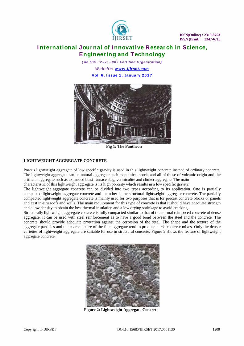
LIGHTWEIGHT AGGREGATE CONCRETE Porous lightweight aggregate of low specific gravity is used in this lightweight concrete instead of ordinary concrete. The lightweight aggregate can be natural aggregate such as pumice, scoria and all of those of volcanic origin and the artificial aggregate such as expanded blast-furnace slag, vermiculite and clinker aggregate. The main characteristic of this lightweight aggregate is its high porosity which results in a low specific gravity. The lightweight aggregate concrete can be divided into two types according to its application. One is partially compacted lightweight aggregate concrete and the other is the structural lightweight aggregate concrete. The partially compacted lightweight aggregate concrete is mainly used for two purposes that is for precast concrete blocks or panels and cast in-situ roofs and walls. The main requirement for this type of concrete is that it should have adequate strength and a low density to obtain the best thermal insulation and a low drying shrinkage to avoid cracking. Structurally lightweight aggregate concrete is fully compacted similar to that of the normal reinforced concrete of dense aggregate. It can be used with steel reinforcement as to have a good bond between the steel and the concrete. The concrete should provide adequate protection against the corrosion of the steel. The shape and the texture of the aggregate particles and the coarse nature of the fine aggregate tend to produce harsh concrete mixes. Only the denser varieties of lightweight aggregate are suitable for use in structural concrete. Figure 2 shows the feature of lightweight aggregate concrete.
Figure 2: Lightweight Aggregate Concrete
ISSN(Online) : 2319-8753
ISSN (Print) : 2347-6710
International Journal of Innovative Research in Science, Engineering and Technology
(An ISO 3297: 2007 Certified Organization)
Website: www.ijirset.com
Vol. 6, Issue 1, January 2017
Copyright to IJIRSET DOI:10.15680/IJIRSET.2017.0601130 1210
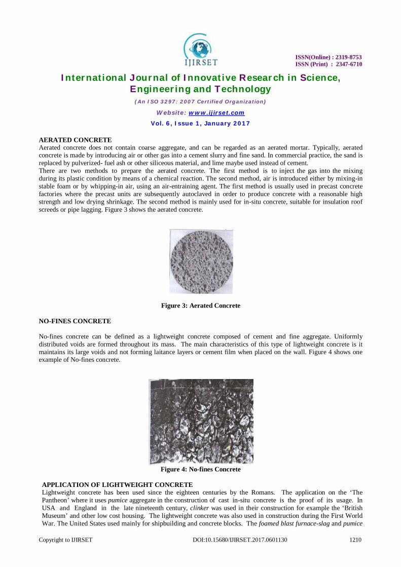
AERATED CONCRETE Aerated concrete does not contain coarse aggregate, and can be regarded as an aerated mortar. Typically, aerated concrete is made by introducing air or other gas into a cement slurry and fine sand. In commercial practice, the sand is replaced by pulverized- fuel ash or other siliceous material, and lime maybe used instead of cement. There are two methods to prepare the aerated concrete. The first method is to inject the gas into the mixing during its plastic condition by means of a chemical reaction. The second method, air is introduced either by mixing-in stable foam or by whipping-in air, using an air-entraining agent. The first method is usually used in precast concrete factories where the precast units are subsequently autoclaved in order to produce concrete with a reasonable high strength and low drying shrinkage. The second method is mainly used for in-situ concrete, suitable for insulation roof screeds or pipe lagging. Figure 3 shows the aerated concrete.
Figure 3: Aerated Concrete NO-FINES CONCRETE
No-fines concrete can be defined as a lightweight concrete composed of cement and fine aggregate. Uniformly distributed voids are formed throughout its mass. The main characteristics of this type of lightweight concrete is it maintains its large voids and not forming laitance layers or cement film when placed on the wall. Figure 4 shows one example of No-fines concrete.
Figure 4: No-fines Concrete
APPLICATION OF LIGHTWEIGHT CONCRETE Lightweight concrete has been used since the eighteen centuries by the Romans. The application on the ‘The Pantheon’ where it uses pumice aggregate in the construction of cast in-situ concrete is the proof of its usage. In USA and England in the late nineteenth century, clinker was used in their construction for example the ‘British Museum’ and other low cost housing. The lightweight concrete was also used in construction during the First World War. The United States used mainly for shipbuilding and concrete blocks. The foamed blast furnace-slag and pumice
ISSN(Online) : 2319-8753
ISSN (Print) : 2347-6710
International Journal of Innovative Research in Science, Engineering and Technology
(An ISO 3297: 2007 Certified Organization)
Website: www.ijirset.com
Vol. 6, Issue 1, January 2017
Copyright to IJIRSET DOI:10.15680/IJIRSET.2017.0601130 1211
aggregate for block making were introduced in England and Sweden around 1930s. Nowadays with the advancement of technology, lightweight concrete expands its uses. For example, in the form of perlite with its outstanding insulating characteristics. It is widely used as loose-fill insulation in masonry construction where it enhances fire ratings, reduces noise transmission, does not rot and termite resistant. It is also used for vessels, roof decks and other applications.
III. METHODOLOGY
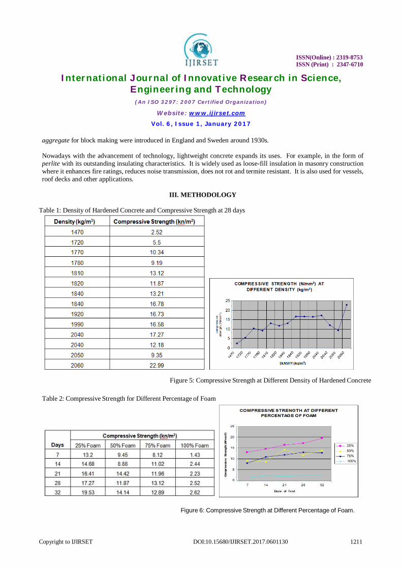
Table 1: Density of Hardened Concrete and Compressive Strength at 28 days
Table 2: Compressive Strength for Different Percentage of Foam
Figure 6: Compressive Strength at Different Percentage of Foam.
Figure 5: Compressive Strength at Different Density of Hardened Concrete
ISSN(Online) : 2319-8753
ISSN (Print) : 2347-6710
International Journal of Innovative Research in Science, Engineering and Technology
(An ISO 3297: 2007 Certified Organization)
Website: www.ijirset.com
Vol. 6, Issue 1, January 2017
Copyright to IJIRSET DOI:10.15680/IJIRSET.2017.0601130 1212
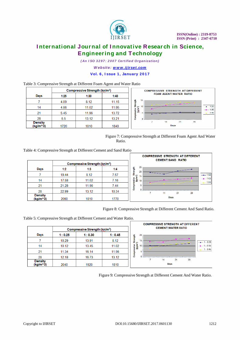
Table 3: Compressive Strength at Different Foam Agent and Water Ratio
Figure 7: Compressive Strength at Different Foam Agent And Water
Ratio.
Table 4: Compressive Strength at Different Cement and Sand Ratio
Figure 8: Compressive Strength at Different Cement And Sand Ratio.
Table 5: Compressive Strength at Different Cement and Water Ratio.
Figure 9: Compressive Strength at Different Cement And Water Ratio.
ISSN(Online) : 2319-8753
ISSN (Print) : 2347-6710
International Journal of Innovative Research in Science, Engineering and Technology
(An ISO 3297: 2007 Certified Organization)
Website: www.ijirset.com
Vol. 6, Issue 1, January 2017
Copyright to IJIRSET DOI:10.15680/IJIRSET.2017.0601130 1213
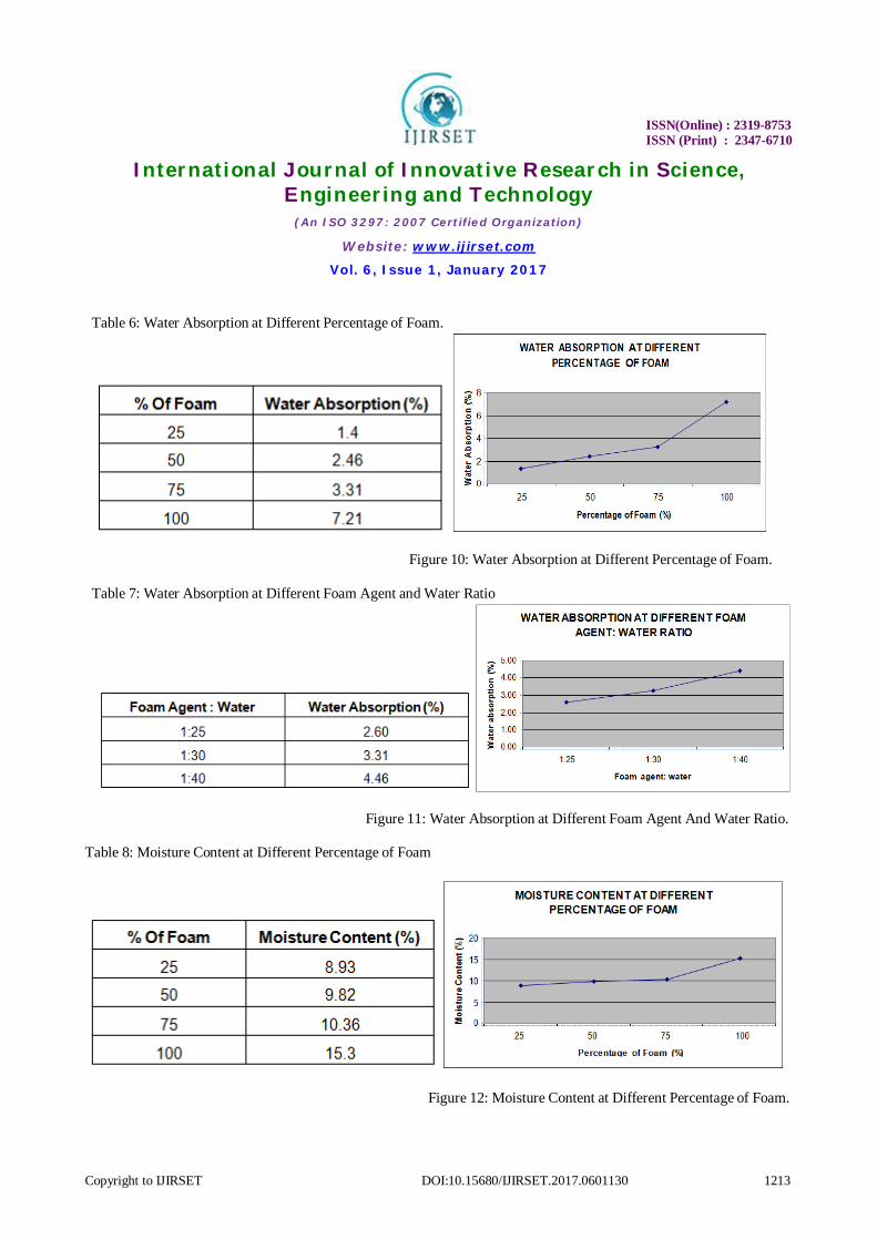
Table 6: Water Absorption at Different Percentage of Foam.
Figure 10: Water Absorption at Different Percentage of Foam. Table 7: Water Absorption at Different Foam Agent and Water Ratio
Figure 11: Water Absorption at Different Foam Agent And Water Ratio. Table 8: Moisture Content at Different Percentage of Foam
Figure 12: Moisture Content at Different Percentage of Foam.
ISSN(Online) : 2319-8753
ISSN (Print) : 2347-6710
International Journal of Innovative Research in Science, Engineering and Technology
(An ISO 3297: 2007 Certified Organization)
Website: www.ijirset.com
Vol. 6, Issue 1, January 2017
Copyright to IJIRSET DOI:10.15680/IJIRSET.2017.0601130 1214
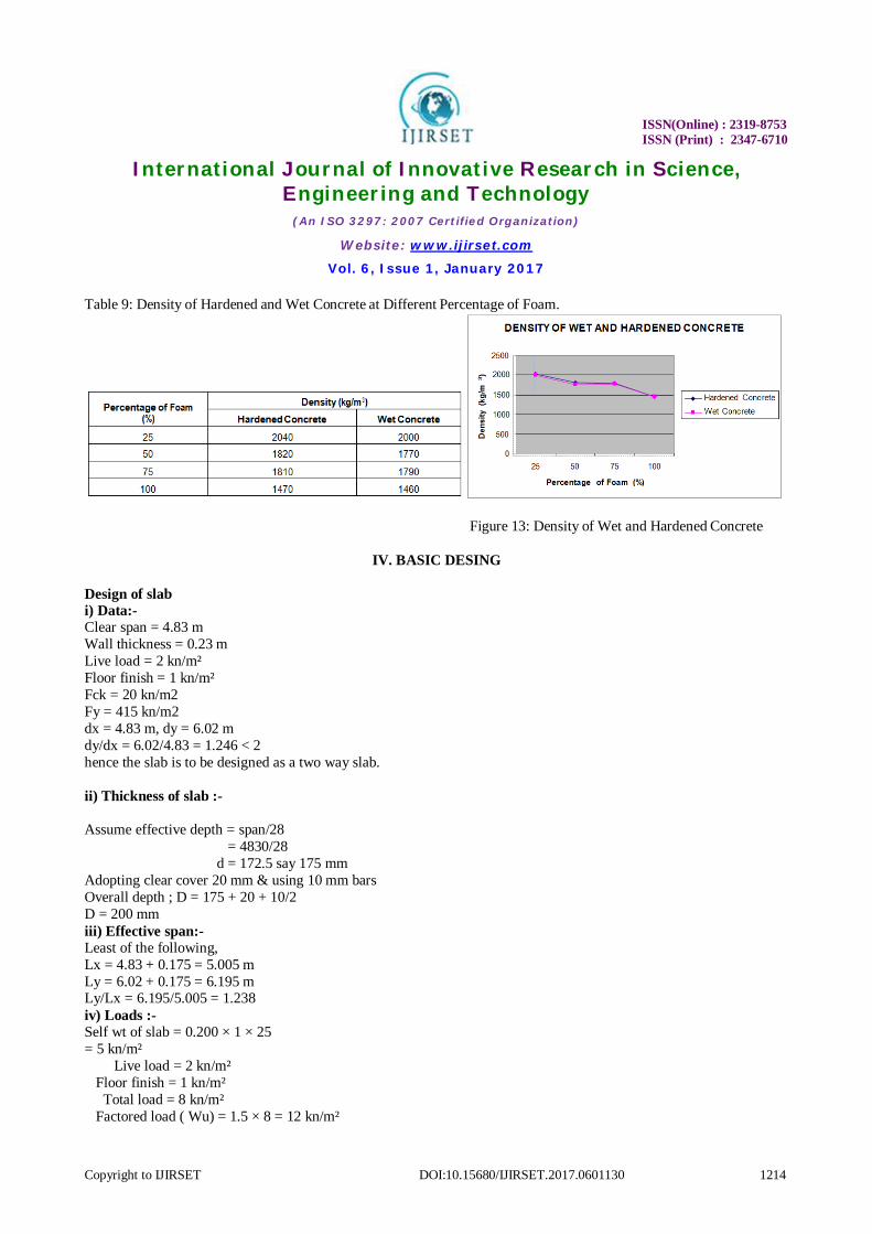
Table 9: Density of Hardened and Wet Concrete at Different Percentage of Foam.
Figure 13: Density of Wet and Hardened Concrete
IV. BASIC DESING Design of slab i) Data:- Clear span = 4.83 m Wall thickness = 0.23 m Live load = 2 kn/m² Floor finish = 1 kn/m² Fck = 20 kn/m2 Fy = 415 kn/m2 dx = 4.83 m, dy = 6.02 m dy/dx = 6.02/4.83 = 1.246 < 2 hence the slab is to be designed as a two way slab. ii) Thickness of slab :- Assume effective depth = span/28 = 4830/28 d = 172.5 say 175 mm Adopting clear cover 20 mm & using 10 mm bars Overall depth ; D = 175 + 20 + 10/2 D = 200 mm iii) Effective span:- Least of the following, Lx = 4.83 + 0.175 = 5.005 m Ly = 6.02 + 0.175 = 6.195 m Ly/Lx = 6.195/5.005 = 1.238 iv) Loads :- Self wt of slab = 0.200 × 1 × 25 = 5 kn/m² Live load = 2 kn/m² Floor finish = 1 kn/m² Total load = 8 kn/m² Factored load ( Wu) = 1.5 × 8 = 12 kn/m²
ISSN(Online) : 2319-8753
ISSN (Print) : 2347-6710
International Journal of Innovative Research in Science, Engineering and Technology
(An ISO 3297: 2007 Certified Organization)
Website: www.ijirset.com
Vol. 6, Issue 1, January 2017
Copyright to IJIRSET DOI:10.15680/IJIRSET.2017.0601130 1215
v) Design moments & shear forces :- The slab is simply supported on all the four sides. The corners are not held down. Hence moment coefficients are obtained from table 27 of IS 456. αₓ = 0.074 αу = 0.056 Mux = αₓ ω lₓ² = 0.074×12×5.005² = 22.24 kn-m Muy = αу ω lₓ² = 0.056×12×5.005² = 16.83 kn-m Factored shear force (Vu) = Wu.l/2 = 12×5.005/2 = 30.03 KN vi) Min depth required :- The minimum depth required to resist the bending moment Mu = 0.138 fck b d² 22.24×10^6 = 0.138×20×1000×d² d = √ ( 22.24×10^6 /0.138×20×1000) d = 89.76 mm < 175 mm vii) Reinforcement :- Along x- direction Mux = 0.87 fy Ast d (1- fy.Ast/ fck.bd) 22.24 × 10^6 = 0.87×415×Ast×175 (1-415×Ast/20×1000×175) Ast = 368.05 mm² Using 8 mm dia bars , spacing of bars S = ast/Ast × 1000 = (Π/4× 8²) /368.05 × 1000 = 136.57 mm say 130 mm Maximum spacing is (1) 3d = 3 × 175 = 525 mm (2) 300 mm which ever is less Hence, provide 8 mm bars at 130 mm c/c Along y-direction These bars will be placed above the bars in x-direction Hence, d = 175-8 = 167 mm Muy = 0.87 fy Ast d (1-fy.Ast/fck.bd) 16.83 × 10^6 = 0.87 × 415 × Ast × 167 (1-415Ast/20×1000×167) Ast = 289.54 mm² Using 8 mm dia bars, spacing of bars S = ast/Ast × 1000 = (Π/4× 8²) /289.54 × 1000 = 173.6 mm say 170 mm Max. spacing is (1) 3d = 3 × 167 = 501 mm (2) 300 mm which ever is less Hence, provide 8 mm bars at 170 mm c/c viii) Reinforcement in Edge strip :- Ast = 0.12% of gross area
ISSN(Online) : 2319-8753
ISSN (Print) : 2347-6710
International Journal of Innovative Research in Science, Engineering and Technology
(An ISO 3297: 2007 Certified Organization)
Website: www.ijirset.com
Vol. 6, Issue 1, January 2017
Copyright to IJIRSET DOI:10.15680/IJIRSET.2017.0601130 1216
= 0.12/100 × 1000 × 200 Ast = 240 mm² Using 8 mm dia bars, spacing of bars S = ast/Ast × 1000 = (Π/4× 8²) /240 × 1000 = 209.44 mm say 200 mm Max. Spacing is (1) 5d = 5 × 175 = 875 mm (2) 450 mm which ever is less Hence provide 8 mm bars at 200 mm c/c in edge strips in both directions ix) Torsion Reinforcement :- Area of reinforcement in each layer At = ¾ Astx = ¾ × 368.05 = 276.04 mm² Distance over which Torsion reinforcement is to be provided = 1/5 short span = 1/5 lx = 5005/5 = 1001 mm Using 6 mm bars, spacing S = ast/Ast × 1000 = (Π/4× 6²) /276.04 × 1000 = 102.43 mm say 100 mm Hence provide 6 mm bars at 100mm c/c at all the four corners in four layers x) Check for deflection :- For simply supported slabs basic value of l/d ratio = 20 Modification factor tension steel F1 % of steel, = Ast/bd × 100 = (368.05/1000×175) × 100 = 0.21 % Fs = 0.58 × fy = 0.58 × 415 = 240 N/mm² From fig 4 of IS 456, modification factor = 1.5 Maximum permitted l/d ratio = 1.5 × 20 = 30 L/d provided = 5005/175 = 28.6 < 30 Hence deflection control is safe b) DESIGN OF BEAM: 1) Data: fck =20N/mm² fy = 415N/mm² l = 6.02N/mm² 2) Depth of beam : Selecting the depth in range of l/12 to l/15 based on stiffness d = 6020/15 = 401.33mm Adopt d = 410mm D = 450 mm 3) Effective span: C/c distance between the supports = 6.02+0.23 = 6.25m
ISSN(Online) : 2319-8753
ISSN (Print) : 2347-6710
International Journal of Innovative Research in Science, Engineering and Technology
(An ISO 3297: 2007 Certified Organization)
Website: www.ijirset.com
Vol. 6, Issue 1, January 2017
Copyright to IJIRSET DOI:10.15680/IJIRSET.2017.0601130 1217
Clear span + d = 6.02+0.41 = 6.43m Hence effective span = 6.25m 4) loads :- Self weight of the beam = 0.23×0.45×1×25 = 2.58kn/m² Load from slab = 8kn/m² Total load = 10.58kn/m² Factored load = 1.5×10.58 =15.87kn/m 5) factored B.M (Mu) & S.F:- Factored B.M (Mu) = Wul²/8 = 15.62× 6.25² = 77.548kn-m Factored s.f (Vu) = Wul/2 = 15.882×6.25 = 49.63kn 6) Depth required:- The min depth req to resist b.m Mu = 0.138Fckbd² 77.548×10^6 = 0.138×20×250×d² D = 349.5 < 410mm Hence ok 7) Tension reinforcement:- Mu = 0.87 FyAstd(1-FyAst) Fckbd Ast = 0.87×415×Ast×410( 1- 415×Ast) 20×230×410 Ast = 604.19mm² Provide 4 bars of 16ф bars Ast provided = 804.248mm² 8) design shear stress :- Nominal shear stress (Tv) = Vu/bd = 49.63×10^3/ 230×410 DESIGN OF COLUMN Load from beam = 76.765 KN Self wt of column = 0.23×1×25 = 5.75 Kn/m Total load = 82.515 Kn/m Factored load (wu) = 1.5×82.515 = 123.77 Kn/m Length of column = 3.0 m Leff = 0.65 l = 0.65×3000 = 1950 mm Check type of the column, 1950/230 = 8.478 < 12 Hence designed as a short column. Side of the column on one side = 230 mm
ISSN(Online) : 2319-8753
ISSN (Print) : 2347-6710
International Journal of Innovative Research in Science, Engineering and Technology
(An ISO 3297: 2007 Certified Organization)
Website: www.ijirset.com
Vol. 6, Issue 1, January 2017
Copyright to IJIRSET DOI:10.15680/IJIRSET.2017.0601130 1218
Net gross area of column is ―Agǁ Assming 1% of steel, Asc = 1% Ag = 0.01 Ag Area of concrete, Ac = Ag- Asc = Ag-0.01Ag = 0.99 Ag For axially loaded short columns, Pu = 0.4fckAc + 0.67fyAsc 123.77×10³ = 0.4×20×0.99Ag + 0.67×415×0.01Ag Ag = 115667.5 mm² Since the column is rectangular & one side of the column is 230 mm, dimension of the other side Ag/230 = 115667.5/230 = 502.9 mm say 500 mm Adopt 230 mm × 500 mm rectangular column, Asc = 0.01 Ag = 0.01 × 115667.5 = 1156.675 mm² Provide 6 mm bars of 16 mm diameter, Asc provided = 1206.4 mm² Lateral ties :- a) ф/4 = ¼ × 16 = 4 mm b) 6 mm Hence, adopt 6 mm diameter bars Pitch of the ties shall be minimum of a) least lateral dimension of column = 230 mm b) 16 times of the dia of longitudinal bar = 16×16 = 256 mm c) 300 mm DESIGN OF FOOTING :- a) Data :- Axial load = 307.068 KN Size of the column = 280×500mm S.B.C of soil = 200kn/m² Fck = 20kn/m² Fy = 415kn 1) Size of footing: Load from the column = 307.068kn Self wt from of footing = 10% of column load = 307.068/10 Total load on the soil =337.775kn Area of footing = 337.775/200 = 1.689m² Provide 1.2×1.5m footing so that the cantilever projection of the footing from the column face is same equal to 1.2-0.23 1.5-0.5 (----------) = (-----------) = 0.5mm 2 2 Area of footing provided = 1.2×1.5mm 2) Upward soil pressure: Factored load Pu = 1.5 ×307.068 = 460.602kn Soil pressure at ultimate load =
ISSN(Online) : 2319-8753
ISSN (Print) : 2347-6710
International Journal of Innovative Research in Science, Engineering and Technology
(An ISO 3297: 2007 Certified Organization)
Website: www.ijirset.com
Vol. 6, Issue 1, January 2017
Copyright to IJIRSET DOI:10.15680/IJIRSET.2017.0601130 1219
Qu = Pu/area of footing Qu = Pu /area of footing Qu = 460.602 /1.2×1.5 = 255.89kn/m² = 0.26n/mm 3) Depth of footing from B.M consideration: The c critical section for B.Mwill be at the face of the column as shown Mu = qul (B-b/8)² = 0.16×1500(1200-230/8)² = 5.733×10^6N-mm 4) Reinforcement: Mu = 0.87 Fy ×415×Ast × 450 (1-415Ast/20×1500×250) Ast =557.25mm² Using 16mm diameter bars, spacing of bars S = ast ×B / Ast = 304.42mm Hence provide 12mm bars at 300mmc/c 5) Check for one way shear: The critical section for one way shear is at a dist d from the face of the column Fact S.F = Vu = soil pressure from the shaded area.
VI. CONCLUSION Lightweight aggregate concrete has been shown by test and by performance to behave structurally in much the same manner as normal weight concrete. For properties which differ, the differences are largely those of degree. The designer must consider the benefits of lighter weight and better insulation in relation to the extra cost of the lightweight mix. The builder must recognize the few different requirements relative to transporting, placing, and finishing. Much helpful information is available from producers of lightweight aggregates through their field control and technical service. We developed cost estimate of the commercial building by using the light weight concrete and other materials such as light weight wood and light weight metals. The goal is to reduce the load component without compromising on the strength to reduce the overall cost of the building and the time frame for construction. We conducted structural analysis by using moment distribution method and designed manually. The required drawings were developed in Auto-cad for this project. Finally, the emphasis is on the benefits of light weight concrete and materials usage to reduce the load on the structure, cost and time of construction. The results, drawings and design and pertinent data is included in the report with conclusions and recommendations.
REFERENCES
[1] Dhir, K., Mays, R.G.C and Chua, H.C., "Lightweight Structural Concrete with Aglite Aggregate: Mix Design and Properties", The International Journal of Cement Composition and Lightweight Concrete, Vol. 6, No. 4, November 1984; pp. 249-261.
[2] AL-Haddad, M. Y., "Durability of Lightweight Porcelinite Concrete Containing Slag Exposed to Solution of Sulfates and Chlorides", M.Sc. Thesis, University of Technology, August 2000.
[3] AL-Timimy, B. A., "Improvement of the Durability ofGlass Fiber Reinforced Concrete", M.Sc. Thesis, University of Technology, April 2001;pp. 160.
[4] Zeng, Q. and Chung, D. D., "Carbon Fiber Reinforced Cement Composites Improved by Using Chemical Agents", Cement and Concrete Research, Vol. 19, 1989; pp. 25–41.
[5] ASTM C192/C192M–02, "Standard Practice for Making and curing Concrete Test Specimens in the Laboratory", Annual Book of ASTM Standards, Vol. 04.02, 2004; pp. 126–133.
[6] Dr. V.Bhaskar Desai and A.Sathyam, “Basic Properties of Artificial Lightweight Aggregate by using Industrial by Product (Fly Ash)”, International Journal of Civil Engineering & Technology (IJCIET), Volume 5, Issue 6, 2014, pp. 65 - 72, ISSN Print: 0976 – 6308, ISSN Online: 0976 – 6316.
[7] Javaid Ahmad and Dr. Javed Ahmad Bhat, “Flexural Strengthening of Timber Beams using Carbon Fiber Reinforced Polymer Plates”,

ISSN(Online) : 2319-8753
ISSN (Print) : 2347-6710
International Journal of Innovative Research in Science, Engineering and Technology
(An ISO 3297: 2007 Certified Organization)
Website: www.ijirset.com
Vol. 6, Issue 1, January 2017
Copyright to IJIRSET DOI:10.15680/IJIRSET.2017.0601130 1220
International Journal of Civil Engineering & Technology (IJCIET), Volume 4, Issue 5, 2013, pp. 61 - 77, ISSN Print: 0976 – 6308, ISSN Online: 0976 – 6316.
[8] Ghassan Subhi Jameel, “Study The Effect of Additionof Wast Plastic on Compressive and Tensile Strengths of Structural Lightweight Concrete Containing Broken Bricks as Acoarse Aggregate”, International Journal of Civil Engineering & Technology (IJCIET), Volume 4, Issue 2, 2013, pp. 415 - 432, ISSN Print: 0976 – 6308, ISSN Online: 0976 – 6316.