weight reduction of intercity bus by different seat ...mmf.cu.edu.tr/tr/dergi/(31_2_2016)/24.pdf ·...
TRANSCRIPT

Çukurova Üniversitesi Mühendislik Mimarlık Fakültesi Dergisi, 31(2), ss. 243-255, Aralık 2016 Çukurova University Journal of the Faculty of Engineering and Architecture,31(2), pp. 243-255, December 2016
Ç.Ü.Müh.Mim.Fak.Dergisi, 31(2), Aralık 2016 243
Weight Reduction of Intercity Bus by Different Seat Construction
Design in Compliance with APTA and FMVSS Standards
Gonca DEDE
*1, Mustafa ÖZCANLI
2
1Amasya University, Technology Faculty, Automotive Engineering Department, Amasya
2Çukurova University, Faculty of Engineering and Architecture, Automotive Engineering
Department, Adana
Geliş tarihi: 07.06.2016 Kabul tarihi: 23.11.2016
Abstract
In this study, weight reduction potential of different seat construction designs has been evaluated for
intercity bus. The passenger seats were designed as CAD model. Finite element method was used to
simulate the tests of FMVSS and APTA standards. Total deformation and maximum stress parameters,
which were obtained by test simulations in FEA software, were analyzed to verify seat designs. This
study results show that using aluminum alloy for seat design instead of St-37 steel provide 50% weight
reductions for seat design. This weight reduction can reduce CO2 emissions and also provide fuel
efficiency over the vehicle‟s operating life.
Keywords: Vehicle efficiency, Emission, Aluminum alloy, Seat
Şehirlerarası Otobüslerde APTA ve FMVSS Standartları’na Uygun Farklı
Koltuk Yapısı Dizaynları ile Ağırlık Azaltılması
Öz
Bu çalışmada, şehirlerarası otobüslerde farklı koltuk yapı dizaynlarının ağırlık azaltma potansiyeli
değerlendirilmiştir. Yolcu koltukları bilgisayar destekli yazılım modeli olarak tasarlanmıştır. FMVSS ve
APTA standartları testlerini simüle etmek için sonlu elemanlar yöntemi kullanılmıştır. Koltuk
dizaynlarını doğrulamak için, sonlu elemanlar analiz metodu ile yapılan test simülasyonları sonucunda
elde edilen toplam deformasyon ve maksimum stres değerleri incelenmiştir. Çalışma sonuçları
koltuklarda çelik yerine alüminyum alaşım kullanmanın %50 ağırlık azalışı sağlayacağını göstermiştir.
Bu ağırlık azalışı araç ömrü süresince CO2 emisyonlarını azaltabilir ve yakıt verimliği de sağlayabilir.
Anahtar Kelimeler: Araç verimliliği, Emisyon, Alüminyum alaşımı, Koltuk
* Sorumlu yazar (Corresponding author): Gonca DEDE, [email protected]

Weight Reduction of Intercity Bus by Different Seat Construction Design in Compliance with APTA and
FMVSS Standards
244 Ç.Ü.Müh.Mim.Fak.Dergisi, 31(2), Aralık 2016
1. INTRODUCTION
Vehicles are one of the most important parts of
daily life. They provide comfort and mobility for
people. In the same time, they affect significantly
the environment during their life time. Greenhouse
gas emissions and energy consumption are
important effects of vehicles.
Previous studies show that approximately 15% of
overall greenhouse gas emissions is occurred due
to transportation sector. Globally, the
transportation sector‟s CO2 emissions represent
23% of overall CO2 emissions from fossil fuel
combustion [1]. In addition to greenhouse gas
emissions, transportation sector accounts for 63%
of the total growth in world consumption of
petroleum and other liquid fuels from 2010 to
2040 in the reference case of International Energy
Outlook 2013 issued by U.S. Department of
Energy [2]. Due to the increments of energy
consumption and greenhouse gas emission, there is
aim for reducing emissions and improving fuel
efficiency in transportation sector.
Weight reduction of vehicles is one of the most
effective means to reduce fuel consumption and
greenhouse gases for vehicle. It has been estimated
that for every 10% of weight eliminated from a
vehicle‟s total weight, fuel economy improves by
7%. This also means that for every kilogram of
weight reduced in a vehicle, there is about 20 kg of
carbon dioxide reduction over the vehicle‟s
operating life [3].
In 1995, Stodolsky et al. performed a study which
estimates total life-cycle energy savings over time
as aluminum-intensive vehicles (AIVs). Their
study showed that 19-31% weight reduction
(270-460 kg) is possible with the intensive use of
aluminum in passenger cars and light trucks,
resulting in a fuel economy improvement of
12.5-20% for AIVs over conventional steel
vehicles. They defined in that at least three ways to
decrease the empty weight of a vehicle in their
study. These three ways are; reducing vehicles‟
size, optimizing its design to minimize weight, and
replacing the materials used in its construction
with lighter mass equivalents. According to the
Stodolsky et al. the third alternative, use of
lightweight materials could provide greater gains
[4].
It can be understood from ratio of overall vehicle
weight; passenger seats have an important energy
saving potential. Approximately, 8% of unloaded
vehicle weight is seat weight [5]. Previous studies
show that using lightweight material can provide a
reduction of weight in between 8, 6% and 30%
[4-8].
In this study weight reduction potential of intercity
bus by different seat construction designs in
compliance with APTA & FMVSS standards has
been investigated theoretically. Analyses were
conducted with final element analysis software.
2. MATERIAL AND METHOD
2.1. Material
Lightweight materials include magnesium,
aluminum, advanced high-strength steels, titanium
as well as polymer-matrix composites reinforced
with glass and carbon fibers. Aluminum material
and its potential for weight reduction are shown in
Table 1 [9].
Table 1. Potential Vehicle Materials Substitution
[9]
Lightweight
Material
Material
Replaced
Mass
Reduction
Relative
Cost
(per part)
Aluminum Steel,
Cast Iron 40-60 1.3-2
Aluminum
Metal Matrix
Composite
Steel
or
Cast Iron
50-65 1.5-3+
In automotive industry, high strength steel,
aluminum alloys, magnesium alloy, composites are
used to reduce weight. These materials must have
the performance requirements (strong, durable,
easily formed and joined into assemblies and
components, sufficiently well-characterized) to use
for vehicle design [10].

Gonca DEDE, Mustafa ÖZCANLI
Ç.Ü.Müh.Mim.Fak.Dergisi, 31(2), Aralık 2016 245
2.1.1. Aluminum Alloys
Aluminum is a light metal and the use of
aluminum offers considerable potential to reduce
the weight of an automobile body. Aluminum is a
soft metal, but high strength-weight ratios can be
achieved in certain alloys.
An aluminum alloy has a chemical composition
where other elements are added to pure aluminum
in order to enhance its properties, primarily to
increase its strength. These other elements include
iron, silicon, copper, magnesium, manganese and
zinc. These alloy are divided several groups
according to alloying elements. One of these
groups is 6xxx series. The 6xxx series are
versatile, heat treatable, highly formable, weldable
and have moderately high strength coupled with
excellent corrosion resistance. Alloys in these
series contain silicon and magnesium in order to
form magnesium silicide within the alloy.
Extrusion products from the 6xxx series are the
first choice for architectural and structural
applications. Alloy 6061 is the most widely used
alloy in this series and is often used in truck and
marine frames [11].
The properties of aluminum alloy are given in
Table 2. Material properties were taken from
MatWeb for Al-6061 [12].
Table 2. Material properties [12]
Material
Elastic
Modulus
(GPa)
Poisson’s
Ratio
Tensile Strength
Yield
(MPa)
Ultimate
(MPa)
Al-6061
T6 68.9 0.33 276 310
2.2. Computer Software
CAD and FEM software were used for the
decision of the design. A reference seat frame
design was made to determine the weight
reductions in this study.
2.3. Seat Dimensions’ Constraints
A CAD-model of seat frame was built based on
reference dimensions of “Standard Bus
Procurement Guidelines RFP”. Reference
dimensions are shown in Figure 1 [13].
Figure 1. Seating dimensions &standard
configuration [13]
2.4. Seat Reference Point
The seat reference point was specified by using
95th
percentile man manikin. The H-point of the
manikin was specified as design reference point as
it is described in SAE J1100 Motor Vehicle
Dimension document. In Figure 2 the manikin,
reference seat structure and H-point of the manikin
are shown [14].
Figure 2. SRP of seat design with 95 percentile
manikin [14]
In automotive sector there are several regulations
which specify the minimum requirements of seats.
According to these regulations, the seats must be
designed to meet various loading conditions like
forward, reward dynamic loads and other static
loads. There are different standards for seats in
Europe and United States. In United States,

Weight Reduction of Intercity Bus by Different Seat Construction Design in Compliance with APTA and
FMVSS Standards
246 Ç.Ü.Müh.Mim.Fak.Dergisi, 31(2), Aralık 2016
American Public Transportation Association
(APTA) Standards (Standard Bus Procurement
Guidelines) is used as a reference by seat
designers. In Table 3 and 4 show an overview of
seat standards. The load cases that are shown in
tables were used in this study. In Figs 3-6, the
force applications of APTA and FMVSS are
shown.
Table 3. Overview of APTA standards (United
States) [15] Load
Case
Experimental
Conditions
Area of
Application
Max.
Deformation
(mm)
Deceleration
10 G Duration:
10 msec
Entire Seat <355 (upper
part of seat)
Vertical
Force 2.23 kN Cushion 6.5
Horizontal
Force 2.23 kN
Seatback
(force equally
distributed
over the seatback)
6.5
Table 4. Overview of FMVSS 207 [16]
Load
Case Experimental Conditions
Area of
Application
Rearward
Force
F=20*9.81*ms
Duration:
Apply-5secs
Hold-5secs
Release-5secs
Center of
Gravity
Moment
Force
M=373 Nm F=373/D
(distance between SRP and
upper cross member)
Duration:
Apply-5secs
Hold-5secs
Release-5secs
Uppermost
Cross
Member
Figure 3. APTA seat tests photos-APTA
horizontal seatback load application
[15]
Figure 4. APTA seat tests photos-APTA vertical
force application [15]
Figure 5. FMVSS 207 seat tests photos-FMVSS
rearward force application [16]

Gonca DEDE, Mustafa ÖZCANLI
Ç.Ü.Müh.Mim.Fak.Dergisi, 31(2), Aralık 2016 247
Figure 6. FMVSS 207 seat tests photos-FMVSS
rearward moment load application [16]
3. RESULT AND DISCUSSION 3.1. Analysis Results of Load Cases for
Reference Seat Design
A reference seat design was built in CAD program.
Reference seat material was selected as St-37. A
finite element model was formed in FEM software.
This final element model consists a seat structure.
Most of seat structures were made of sheet and
tube. In FEM analysis three type of elements are
used; 3D elements, 2D (2D solids, plates and
shells) elements, and 1D (truss and beam)
elements. Usually, 2D elements should be used for
areas/parts that have a plate- or shell-like geometry
[17]. Therefore, in geometry modeling for the seat
parts where 2D elements are to be used, the
geometrical mid surfaces were created. Shell
element type is used for the seat parts [18].
The mesh only needs to be finer in areas of
importance, such as areas of interest, and expected
zones of stress concentration, such as at re-entrant
corners, holes; slots; notches; or cracks. For seat
FEM model, the areas of holes and attachment
points were meshed finer. Regularly shaped
elements are not possible for every geometry, thus
element distortions are possible in meshing. Mesh
quality can be controlled by these element
distortions limitations. Element quality, aspect
ratio, jacobian ratio, wrapping factor, parallel
deviation, maximum corner deviation, skewness
are used to control mesh quality. The finite
element model mesh quality was control criteria.
Weld connections were simulated as bonded
contact. Bolt connections were modeled by using
line elements. The surface of sidewall and floor
were defined as fixed support [19].
The reference seat was analyzed according to the
APTA and FMVSS. The reference seat passed all
tests.
3.2. Seat Design for Al-6061 T6
3.2.1. Design Step 1
Aluminum 6061 T6 was used instead of St-37 with
same design. When the seat was analyzed for the
APTA horizontal force load case and FMVSS
rearward moment test, the maximum stress of the
frame was above the ultimate tensile strength of
material (Figure 7).
3.2.2. Design Step 2
Seat and floor attachment part dimensions were
changed. The design passed the FMVSS rearward
moment test. However, the design didn‟t pass the
APTA horizontal force application test. The
maximum deflection was above the requirement
(Figure 7).
3.2.3. Design Step 3
The seatback deformation was above the
regulation; therefore, the gaps on seatbacks were
removed (Figure 8).
3.2.4. Design Step 4
The total deformation was above the regulation;
therefore, the gaps on upper seat frame parts were
removed. (Figure 8).
3.2.5. Design Step 5
The total deformation was above the regulation;
therefore, the seat frame wall thickness was
increased (Figure 9).
Weight Reduction of Intercity Bus by Different Seat Construction Design in Compliance with APTA and
FMVSS Standards
248 Ç.Ü.Müh.Mim.Fak.Dergisi, 31(2), Aralık 2016
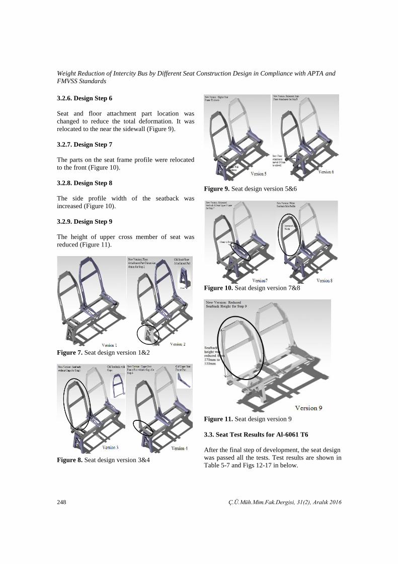
3.2.6. Design Step 6
Seat and floor attachment part location was
changed to reduce the total deformation. It was
relocated to the near the sidewall (Figure 9).
3.2.7. Design Step 7
The parts on the seat frame profile were relocated
to the front (Figure 10).
3.2.8. Design Step 8
The side profile width of the seatback was
increased (Figure 10).
3.2.9. Design Step 9
The height of upper cross member of seat was
reduced (Figure 11).
Figure 7. Seat design version 1&2
Figure 8. Seat design version 3&4
Figure 9. Seat design version 5&6
Figure 10. Seat design version 7&8
Figure 11. Seat design version 9
3.3. Seat Test Results for Al-6061 T6
After the final step of development, the seat design
was passed all the tests. Test results are shown in
Table 5-7 and Figs 12-17 in below.

Gonca DEDE, Mustafa ÖZCANLI
Ç.Ü.Müh.Mim.Fak.Dergisi, 31(2), Aralık 2016 249
Table 5. Wall thickness and weights for reference design and al-6061 design
Part Name
Reference
Al- 6061
Reference Seat
Weight (kg)
Al-6061
Seat
Weight(kg) Wall Thickness(mm)
Seat-Floor Attachment 4 4 2.133 0.90
Seat Frame 2 4 4.398 3.14
Seat Upper Frame 6 6 0.918 0.46
Sidewall Attachment 5 5 0.874 0.22
Seatback 10 10 5.414 2.42
Total Weight 21.927 10.93
Table 6. Al-6061 seat analysis results for same design with reference design
Table 7. Wall thickness and weights for reference design and al-6061 final design
Standards Load Case
Requirement
Max.
Deformation
(mm)
Max.
Deformation
(mm)
Max. Stress
(MPa)
AP
TA
Lo
ad
Ca
ses Deceleration
<355 (upper part
of seat) 3.99 16.73
Vertical Force 6.5 0.29 17.8
Horizontal Force 6.5 6.44 130.13
FM
VS
S
Rearward Force Application
Test Simulation - 2.72 74.4
Rearward Moment
Application Test Simulation - 36.28 175.61
Standards Load Case
Requirement
Max.
Deformation
(mm)
Max.
Deformation
(mm)
Max. Stress
(MPa)
AP
TA
Lo
ad
Ca
ses
Deceleration <355 (upper part
of seat) 7.1 49.7
Vertical Force 6.5 0.37 84.2
Horizontal Force 6.5 17.2 312
FM
VS
S
Rearward Force Application
Test Simulation - 5.6 82.6
Rearward Moment
Application Test Simulation - 64 337

Weight Reduction of Intercity Bus by Different Seat Construction Design in Compliance with APTA and
FMVSS Standards
250 Ç.Ü.Müh.Mim.Fak.Dergisi, 31(2), Aralık 2016
3.3.1. APTA Regulation 80 Deceleration Load
Case Analysis
The seat design was analyzed according to the
APTA; 10G deceleration was applied to the seat
during 10 milliseconds. The maximum total
deformation of the entire seat is 3.99 mm. This
value is below the requirement of the APTA
standard. The maximum stress of the seat design is
16.73 MPa, this values is below the tensile
strength of Al-6061.
Figure 12. APTA& ECE R80 deceleration load case analysis results a) Total deformation b) Maximum
equivalent stress
3.3.2. APTA Horizontal Force to Seatback Load
Case Analysis
The seat design was analyzed according to the
APTA, 2.23 kN load was applied to the upper
cross member of seatback through the loading bar.
The maximum total deformation of the entire seat
is 6.44 mm. This value is below the requirement of
the APTA standard.
Figure 13. APTA horizontal force to seatback load case analysis a) Total deformation b) Maximum
equivalent stress

Gonca DEDE, Mustafa ÖZCANLI
Ç.Ü.Müh.Mim.Fak.Dergisi, 31(2), Aralık 2016 251
3.3.3. APTA Vertical Force to Seat Cushion
Part Load Case Analysis
The seat design was analyzed according to the
APTA, 2.23 kN load was applied to the upper
cross member of seatback through the loading bar.
The maximum total deformation of the entire seat
is below 1 mm. This value is below the
requirement of the APTA standard.
Figure 14. APTA vertical force to seat cushion part load case analysis a) Total deformation b) Maximum
equivalent stress
3.3.4. Rearward Force Application Test
Simulation
The force was applied through the center of gravity
on a rigid member. The force, which was
determined according to the FMVSS 207, was
equal to the 20 times the mass of the seat in
kilograms multiplied by 9.8. The force was applied
in 5 seconds, hold for 5 seconds and released in
5 seconds.
The force is expressed as
F= 20 gms (N) (1)
where g is gravity force and ms is mass of the seat.
The force is determined as
F= 20x10.93x9.81 N =2145 N (2)
Figure 15. Rearward force application test simulation a) Total deformation b) Maximum equivalent stress

Weight Reduction of Intercity Bus by Different Seat Construction Design in Compliance with APTA and
FMVSS Standards
252 Ç.Ü.Müh.Mim.Fak.Dergisi, 31(2), Aralık 2016
3.3.5. Moment applied in a Rearward
Longitudinal Direction Test Simulation
The force was applied to the upper cross-member
of the seat backs. All loads were applied in
5 seconds, hold for 5 seconds and released in
5 seconds.
The force is expressed as
/F M D (3)
where M= 373 Nm/occupant, D is the Vertical
distance between SRP plane and upper cross
member.
The force is determined as
F=373/0,329 =1133N (4)
Figure 16. Vertical distance between SRP plane
and upper cross member
Figure 17. Rearward moment application test simulation a) Total deformation b) Maximum equivalent
stress
3.4. Comparison of Seat Design
The main objective of this study is reducing the
seat weight. Therefore, lightweight material was
used to reduce the weight. An aluminum alloy
was selected. The seat structures were tested
safety standards that are set for bus seats. The
seat designs are shown in Figure 18.
The aluminum alloy design has higher wall
thickness for seat frame part. Table 8 represents
the seat and floor attachment part of aluminum
alloy design are closer to the sidewall.

Gonca DEDE, Mustafa ÖZCANLI
Ç.Ü.Müh.Mim.Fak.Dergisi, 31(2), Aralık 2016 253
Figure 18. Seat designs a) Reference seat design b) Aluminum alloy seat design
Table 8. Comparison of seat designs
Part Name
Reference Al-
6061 Reference
Al-
6061
Wall
Thickness(mm) Seat Weight (kg)
Seat-Floor
Attachment 4 4 2.133 0.9
Seat Frame 2 4 4.398 3.14
Seat Upper
Frame 6 6 0.918 0.46
Sidewall
Attachment 5 5 0.83 0.22
Seatback 10 10 5.447 2.42
Total Weight 21.927 10.93
As seen in the Table 9, the aluminum alloy
decreases the reference seat‟s total mass 21.92 to
10.99 kg (50% in mass).
Table 9. Weight comparison
St-37 Al 6061
Total Weight (kg) 21.92 10.93
Weight Reduction (kg) 0 10.99
Weight Reduction (%) 0 50.14
Bus Weight Reduction* (%) 0 2.83
* This calculation is done for a bus with 40 seats
In addition to fact that the aluminum alloy
provides weight reduction, when we calculate the
factor safety for final design, it can be seen that its
factor safety is about 1,6.
The factor of safety expressed as
factor of safety material yield stress
ma imum design stress (5)
for design with Al 6061 is determined as
(6)
where material yield stress is equal to 276 Mpa
from Table 2 and maximum design stress is
175 Mpa from Table 7.
Reducing vehicle weight can help decrease energy
and petroleum consumption by increasing
efficiency. In addition, it decreases the greenhouse
gas emissions. Ghassmieh estimated that for every
10% of weight eliminated from a vehicle‟s total
weight, fuel economy improves by 7% and for
every kilogram of weight reduced in a vehicle;
there is about 20 kg of carbon dioxide reduction
[3]. According to the Ghassmieh‟s estimations
fuel economy and CO2 reductions were calculated

Weight Reduction of Intercity Bus by Different Seat Construction Design in Compliance with APTA and
FMVSS Standards
254 Ç.Ü.Müh.Mim.Fak.Dergisi, 31(2), Aralık 2016
approximately for this study, calculation results are
shown in Table 10.
Table 10. Fuel economy and CO2 reduction
calculation for Al-6061 seat design
Estimation Calculation
for Al 6061
Vehicle
Weight
Reduction
Fuel
Economy
Vehicle
Weight
Reduction
Fuel
Economy
10% 7% 3% 2.1%
Weight
Reduction
CO2
Reduction
Weight
Reduction *
CO2
Reduction *
1 kg 20 kg 440 kg 8800 kg
* This calculation is done for a bus with 40 seats
4. CONCLUSION
The aim of this study was designing lightweight
seat design for an intercity bus. Aluminum alloys
material was used to reduce the weight of the seat
design.
Conclusions based on the comparison of designs
with reference seat design
50% weight reduction was obtained by using
aluminum alloy as seat material.
If aluminum alloy design used for a bus with
40 seat 2.1% fuel economy could be obtained
and 8800 kg CO2 emission could be prevented
during lifetime in comparison with the
reference design.
5. REFERENCES
1. International Transport Forum, Reducing
Transport Greenhouse Gas Emissions-Trends
& Data, 2010. 15.07.2015, 2010.
2. U.S. Energy Information Agency, International
Energy Outlook, 2013. 15.07.15, 2013.
3. Ghassemieh, E., 2011. Materials in Automotive
Application, State of the Art and Prospects,
New Trends Developments in Automotive
Industry, Chiaberge, M., 978-953-307-999-8
4. Stodolsky, F., Vyas, A., Cuenca, R., Gaines,
L., 1995. Life-Cycle Energy Savings Potential
from Aluminum-Intensive Vehicles, 1995.
Total Life Cycle Conference & Exposition,
Vienna, Austria.
5. Yuce, C., 2013. Yeni Nesil Ticari Araçlar için
Hafifletilmiş Yolcu Koltuğu Tasarımı ve
Prototip İmalatı, Master‟s Degree, Uludağ
Univercity, Institute of Science and
Technology.
6. Burman, R., 1997. 11-IBCAM Vehicle
Technology „97, Automotive Engineer.
7. García Nieto, P.J., Vilan, J.V., Del Coz Diaz, J.J. Matias, J.M., 2009. Analysis and Study of
an Automobile Rear Seat by FEM,
International Journal of Computer
Mathematics, 86;640–664.
8. Steinwall, J., Viippola, P., 2014. Concept
Development of a Lightweight Driver‟s Seat
Structure & Adjustment System, Master‟s
Degree, Department of Product and Production
Development, Chalmers University of
Technology.
9. U.S. Department of Energy, Multi-Year
Program Plan 2011 – 2015, 16.07.15, 2010.
10. Cheah, L.W., 2010. Cars on a Diet: The
Material and Energy Impacts of Passenger
Vehicle Weight Reduction in the U.S., Doctor
of Philosophy, Engineering Systems at The
Massachusetts Institute of Technology.
11. The Aluminum Association, Aluminum Alloys
101, The Aluminum Association, 03.08.2015.
12. MatWeb,LLC.,http://www.matweb.com/search
/DataSheet.aspx?MatGUID=90404a0c001c401
6b2b359a6c19f9127, 03.08.2015.
13. American Public Transportation Association,
APTA Bus Procurement Guidelines,
03.08.2013.
14. The Executive Director Office of the Federal
Register Washington, 1984. D.C., SAE 1100:
Motor Vehicle Dimensions, 4.08.2015.
15. Bergeron, F., Audet, J.F., 2004. Feasibility
Study for the Development and Marketing of
Magnesium Seats for Motor Coaches and other
modes of Public Transit, Feasibility Report, TP
14275E, Transportation Development Centre,
Canada.
16. U.S. Government Publishing Office, 2008.
Federal Motor Vehicle and Safety Standard,
Standard No. 207, Seating Systems, 4.08.2015.
17. Liu, S.S.Q.G.R., 2003. The Finite Element

Gonca DEDE, Mustafa ÖZCANLI
Ç.Ü.Müh.Mim.Fak.Dergisi, 31(2), Aralık 2016 255
Method: A Practical Course. Butterworth-
Heinemann.
18. ANSYS, Inc., ANSYS Meshing User‟s Guide,
Knowl. Creat. Diffus. Util., vol. 15317.
19. Ansys, 2014. An Overview of Methods for
Modelling Bolts in ANSYS V15, in Ansys
Regional Conference.

Weight Reduction of Intercity Bus by Different Seat Construction Design in Compliance with APTA and
FMVSS Standards
256 Ç.Ü.Müh.Mim.Fak.Dergisi, 31(2), Aralık 2016