welch allyn 52000 service manual - meena medical equipment
TRANSCRIPT

Service Manual
Vital Signs Monitor (52000 Series)
Protocol QuikSigns
(52000 Series)
Welch Allyn, Inc.4341 State Street Road
P.O. Box 220Skaneateles Falls, NY 13153-0220
95P445E Rev. C Copyright 1999

Revision Information
Service Manual 95P445E Rev. C Welch Allyn Vital Signs Monitor i
Revision History
Drawings and/or illustrations and/or part numbers in this document are for refer-ence only. For the most current revision call the Welch Allyn Customer Service phone number listed in Section 1.
Date ECN# Revision Description Originator Approval 06/10/1999 A Introduction of Service Manual JDB JDB 10/06/03 5-46657 B Correction made to
temperature accuracy, part numbers, error codes and updates to the drawings. Revised to meet Service Manual Work Instructions.
JDB, DLK DLK
12/12/03 5-46990 C Revised service and support details in Section 1 and Appendix E. Re-formatted units of measurement to meet NIST Standards. Corrected grammar and punctuation. Added page numbering to blank pages.
DLK RJS

ii Welch Allyn Vital Signs Monitor Service Manual 95P445E Rev. C

Table Of Contents
Service Manual 95P445E Rev. C Welch Allyn Vital Signs Monitor iii
Section 1: General InformationTo Service Personnel...................................................................................................... 1Intent of Manual and Product Scope ............................................................................. 1Limited Warranty .......................................................................................................... 2Owner Maintenance ...................................................................................................... 2Warranty, Service, and Spare Parts ................................................................................ 2Periodic Calibration Requirements ................................................................................ 3Incoming Inspection ...................................................................................................... 4Introduction .................................................................................................................. 5Basic System Operation ................................................................................................. 5Specifications............................................................................................................... 10Mechanical Specifications............................................................................................ 12Electrical Specifications ............................................................................................... 13Environmental Specifications....................................................................................... 13Identification Label and Serial Numbering System Defined ......................................... 14Firmware Identification ............................................................................................... 14
Section 2: Calibration/ServiceTools required for Service............................................................................................ 15Test Equipment Bench Layout ..................................................................................... 16Voltage Calibration ..................................................................................................... 17Pressure Calibration .................................................................................................... 17Loading Unit Software................................................................................................. 18
Section 3: TroubleshootingDiagnostic Procedure for Returned Units..................................................................... 19Battery Voltage Check ................................................................................................. 19LED Functional Check ................................................................................................ 19BP Functional Check ................................................................................................... 19Printer Functional Check ............................................................................................. 20SpO2 Functional Check ............................................................................................... 20Temperature Functional Check.................................................................................... 20Communication Functional Check .............................................................................. 20Calibration Tests ......................................................................................................... 21Current Tests............................................................................................................... 22Noise Levels ................................................................................................................ 22Button Test.................................................................................................................. 22 Print Quality............................................................................................................... 23Pneumatic Tests........................................................................................................... 23Fail Safe Testing .......................................................................................................... 24SpO2 Tests................................................................................................................... 25Temperature Tests ....................................................................................................... 26Nurse Call Testing....................................................................................................... 26Self Diagnostic Fault Codes ......................................................................................... 27Main Board/Blood Pressure Error Codes ..................................................................... 27SpO2 Error Codes........................................................................................................ 27

Table Of Contents
iv Welch Allyn Vital Signs Monitor Service Manual 95P445E Rev. C
Temperature Error Codes ............................................................................................ 28Temperature Error Code Correction............................................................................ 28Complaint / Cause / Corrective Action ........................................................................ 29
Section 4 Disassembly/AssemblyFront Housing ............................................................................................................. 33Main PCB.................................................................................................................... 34DC to DC Converter (SpO2 Units Only)...................................................................... 36Pressure Transducers on Main PCB............................................................................. 38Display PCB Removal.................................................................................................. 40Key Pad (Switch Array) ............................................................................................... 42Temperature PCB ........................................................................................................ 44Specific Oxygen Board (Nonin SpO2 PCB) .................................................................. 46Specific Oxygen Board (Nellcor SpO2 PCB - MP205 or MP506)................................. 48Pump/Motor Assembly ................................................................................................ 50Valve (Pneutronics)...................................................................................................... 52Printer/Printer PCB/Keypad ......................................................................................... 54Battery Placement ........................................................................................................ 56
Appendix A: Repair Parts ListRepair Parts List ........................................................................................................... 57
Appendix B: Product Structure/AccessoriesProduct Structure/Accessories ....................................................................................... 63
Appendix C: Assembly Drawings/Board layoutAssembly Drawings/Board Layout................................................................................ 69
Appendix D: Repair Test SpecificationsRepair Tests Specifications ........................................................................................... 75Unit Manometer Calibration ....................................................................................... 76Manometer Accuracy Test........................................................................................... 76Deflation Test.............................................................................................................. 77Voltage Testing............................................................................................................ 77Unit Current Tests ....................................................................................................... 77Noise Tes..................................................................................................................... 77Hardware Fail-safe Tests ............................................................................................. 77SpO2 Tests................................................................................................................... 78Temperature Option Testing ....................................................................................... 79Printer Option Testing................................................................................................. 79RS232 Testing ............................................................................................................. 79RS423 Testing (Acuity Monitors) ................................................................................ 79
Appendix E: Check List For Service WorkCheck List for Service Work ......................................................................................... 83

List of Tables and Figures
Service Manual 95P445E Rev. C Welch Allyn Vital Signs Monitor v
List Of Tables
Table 2-1. Tools required for calibration and repair of the Vital Signs Monitor. ......... 15Table 3-1. Button press response table.......................................................................... 25Table 3-2. Main board/blood pressure error code table. .............................................. 29Table 3-3. SpO2 error code table. ................................................................................ 27Table 3-4. Temperature error code table. .................................................................... 28Table 3-5. General Guide to Problems and Corrective Actions. ................................... 29
List Of Figures
Figure 1-1. Nurse call interface diagram. ..................................................................... 10Figure 1-2. Serial number label. ................................................................................... 14Figure 2-1. Bench layout for re-calibration and testing of the Vital Signs Monitor. ..... 16Figure 4-1. DC to DC replacement. ............................................................................. 37Figure 4-2. Pressure transducer replacement ............................................................... . 39Figure 4-3. RTV removal from NONIN SpO2 PCB..................................................... 47Figure 4-4. SpO2 jack, wire side .................................................................................. 47Figure 4-5. Bottom view of valve (Pneutronics). .......................................................... 53

vi Welch Allyn Vital Signs Monitor Service Manual 95P445E Rev. C

General Information Section 1
Service Manual 95P445E Rev. C Welch Allyn Vital Signs Monitor 1
To Service Personnel Read and understand the Vital Signs Monitor Operator's Manual and this service manual. The information contained in these publications are subject to change without notice and should not be construed as a commitment by Welch Allyn, Inc.
Welch Allyn assumes no responsibility for any errors that may appear in this manual. If the product and/or its operation varies significantly from any description herein, please contact the following:
Welch Allyn, Inc. 1-800-535-6663315-685-4100Fax (315)-685-3361
Welch Allyn, Inc.4341 State Street RoadSkaneateles Falls, NY 13153
This product has been designed to provide a high degree of safety and reliability. However, we can not guarantee against: deterioration of components due to aging, normal wear, tampering, and abuse.
Only Authorized Welch Allyn personnel or agents must perform all service and repairs, using approved Welch Allyn replacement parts and approved process materials. Failure to follow these guidelines will invalidate the product warranty. Please refer to the product warranty for specific coverage.
Intent of Manual and Product ScopeThis manual provides technical service and re-calibration information to technicians authorized to repair and re calibrate Welch Allyn, Inc. products. When used in conjunction with the required test equipment and tools, technicians will be able to diagnose, repair, and re-calibrate, and test the Vital Signs Monitor.
The manual includes: Re-calibration instructions, fault/cause analysis, step-by-step disassembly and re-assembly procedures, repair, adjustment, and re-test procedures.

2 Welch Allyn Vital Signs Monitor Monitor Service Manual 95P445E Rev. C
Section 1 General Information
Limited WarrantyWelch Allyn, Inc. warrants the Vital Signs Monitor, when new, to be free of defects in material and workmanship and to perform in accordance with manufacturer's specifications for a period of two years from the date of purchase from Welch Allyn, Inc. or its authorized distributors or agents. Accessories (battery, cuff, tubing, temperature probe, SpO2 sensor and transformer) carry a one-year warranty. Welch Allyn, Inc. will either repair or replace any components found to be defective or at variance from manufacturer's specifications within this time at no cost to the customer. It shall be the purchaser's responsibility to return the instrument to Welch Allyn, Inc. or an authorized distributor, agent or service representative. This warranty does not include breakage or failure due to tampering, misuse, neglect, accidents, modification or shipping. This warranty is also void if the instrument is not used in accordance with manufacturer's recommendations or if repaired by other than Welch Allyn, Inc. or an authorized agent. Purchase date determines warranty requirements. No other express warranty is given.
To receive service assistance or to ask questions regarding this warranty, please call your nearest Welch Allyn Technical Support Center.
Owner MaintenanceOwner Maintenance: Non-Technical customers can perform normal maintenance per the instructions provided in the Operator's Manual. End users will be able to perform basic operations such as replacement of: hoses, cuffs, probes, and batteries. On this level the unit will not be opened (except for the battery housing). Opening of the Vital Signs Monitor by untrained individuals will damage the unit and void the warranty.
Warranty, Service, and Spare PartsWarranty ServiceAll repairs on products under warranty must be performed or approved by Welch Allyn. Unauthorized repairs will void the warranty. In addition, whether or not covered under warranty, any product repair shall exclusively be performed by Welch Allyn trained and certified service personnel.
Assistance and PartsIf the product fails to function properly or if assistance, service, or spare parts are required, contact the nearest Welch Allyn Technical Support Center.
USA 1-800-535-6663 Latin America (+1) 305-669-9591
European Call Center (+353) 469-067-790 United Kingdom 0-207-365-6780
France (+33) 1-60-09-33-66 Germany (+49) 7477-927-173
Canada 1-800-561-8797 South Africa (+27) 11-777-7509

General Information Section 1
Service Manual 95P445E Rev. C Welch Allyn Vital Signs Monitor 3
Australia (+61) 2-9638-3000 Singapore (+65) 6291-0882
Japan (+81) 3-5212-7391 China (+86) 21-6327-9631
Before contacting Welch Allyn it is helpful to attempt to duplicate the problem and to check all accessories to ensure that they are not the cause of the problem.
When calling, please be prepared to provide:• The product name, model number and complete description of the problem• The serial number of your product (if applicable)• The complete name, address and phone number of your facility• For out-of-warranty repairs or spare parts orders, a purchase order (or credit card)
number • The required spare or replacement part number(s), for parts order
RepairsIf your product requires warranty, extended warranty, or non-warranty repair service, please call first the nearest Welch Allyn Technical Support Center. A representative will assist you in troubleshooting the problem and will make every effort to solve the problem over the phone, avoiding potential unnecessary return.
In case the return cannot be avoided, the representative will record all necessary information and will provide a Return Material Authorization (RMA) number, as well as the appropriate return address.
A Return Material Authorization (RMA) number must be obtained prior to any return. Be sure to note this number on the outside of your shipping box.
Packing Instructions• If you have to return goods for service, follow these recommended packing instructions:• Remove all hoses, cables, sensors, power cords, and ancillary products (as appropriate)
before packing, unless you suspect they are associated with the problem.• Wherever possible use the original shipping carton and packing materials.• Include a packing list and the Welch Allyn Return Material Authorization (RMA)
number.• Be sure to note the (RMA) number on the outside of your shipping box.
It is recommended that all returned goods be insured. Claims for loss or damage to the product must be initiated by the sender.
Periodic Calibration RequirementsWelch Allyn, Inc. recommends that the calibration of the Vital Signs Monitor be checked on a yearly basis for BP, Temperature and SpO2 (if applicable).

4 Welch Allyn Vital Signs Monitor Monitor Service Manual 95P445E Rev. C
Section 1 General Information
Incoming InspectionNOTE: Use the following guidelines when unpacking the Vital Signs Monitor from its shipping carton.
1. Before opening the Vital Signs Monitor shipping carton, check for damage.
2. If damage is apparent, stop unpacking the carton and contact the shipping company forfurther instructions. If the carton is intact, unpack the Vital Signs Monitor.
3. With the Vital Signs Monitor out of its carton, check to see that all the items listed on the packing slip are included.
4. If an item is missing, first check the carton, then check with your receiving department. If necessary contact your nearest Welch Allyn representative.
5. Clean and disinfect by following the instructions printed in the Operator’s Manual.
Note: Perform all functional tests as listed in Section 3 before and after servicing. Operate the Vital Signs Monitor to verify the customer complaint before making any changes to the unit. Call the customer if the complaint is unclear.
If the unit has caused or is suspected of having caused an injury of any type: DO NOTDISASSEMBLE OR REPAIR THE UNIT IN ANY WAY. Contact your nearest Welch Allyn Customer Support Center immediately.
General Information Section 1
Service Manual 95P445E Rev. C Welch Allyn Vital Signs Monitor 5
IntroductionThe Welch Allyn Vital Signs Monitor, also marketed as QuickSigns, is designed to non-invasively and automatically measure systolic and diastolic pressure, pulse rate, temperature and oxygen saturation (SpO2) for adult and pediatric patients. THE WELCH ALLYN VITAL SIGNS MONITOR IS NOT TO BE USED ON NEONATAL PATIENTS. All blood pressure, pulse, temperature and SpO2 values can be viewed on a large, easy-to-read display, and may be printed via the integrated printer as desired.
The rechargeable lead acid battery and variety of mounting accessories make the Welch Allyn Vital Signs Monitor convenient for many locations. The operator may choose any combination of simultaneous measurement modalities. This flexibility, combined with features such as programmable alarms and automatic BP cycles, makes the Welch Allyn Vital Signs Monitor ideal for a wide variety of patient monitoring needs.
Refer to the Welch Allyn Vital Signs Monitor Operator’s Manual for complete information on Indications For Use, Special Features, Supplies and Accessories.
Basic System OperationBlood Pressure Operating ModesWhen a blood pressure measurement cycle is initiated, the cuff will automatically inflate to the default pressure level.
The cuff will immediately begin to deflate in a stepped fashion and will determine systolic pressure and diastolic pressure from the pulses sensed by the cuff at various pressure levels. This is the oscillometric method of non-invasive blood pressure monitoring.
Blood pressure measurements may be initiated manually, or automatically at time intervals determined by the user.
At the completion of a measurement cycle the systolic and diastolic pressures are displayed. If the Monitor is in Automatic Mode, the measured values are kept on display until the next BP measurement is initiated. When not in Automatic Mode, the measured values are displayed for two minutes, after which time the display screen is blanked. The most recent BP measurement may be recalled by pressing the REVIEW button.
When in Automatic Mode, if the unit is unable to determine the systolic or diastolic value, the measurement will be automatically repeated once.
Blood Pressure Manual ModeIn the Manual Mode, a single blood pressure determination is made only when the START button is pushed. The manual mode is the default mode of operation for blood pressure determinations.
A measurement cycle may be cancelled at any time by pressing the CANCEL button. This action immediately initiates a rapid cuff deflation.

6 Welch Allyn Vital Signs Monitor Monitor Service Manual 95P445E Rev. C
Section 1 General Information
The blood pressure measurement data will appear on the display immediately following the measurement. The display will blank after two minutes. If the display is blank, pressing the REVIEW button on the front panel will recall the measurement. Up to 99 prior measurements are available for review or printing.
In Blood Pressure Manual Mode, the following alarm limits may be activated; SYSTOLIC HIGH LIMIT, SYSTOLIC LOW LIMIT, DIASTOLIC HIGH LIMIT, DIASTOLIC LOW LIMIT, PULSE RATE HIGH LIMIT and PULSE RATE LOW LIMIT. Blood pressure determinations, which activate alarms, are indicated by flashing displays and a repetitive audible tone. If an alarm limit is violated, subsequent blood pressure determinations may be made only after the alarm condition is reset by pressing any button on the Monitor's display.
Blood Pressure Automatic ModeThe Automatic Blood Pressure Mode is entered by pressing the AUTO button. Pressing the AUTO button displays a choice of 11 cycle interval times as follows: "St" (STAT mode), 1 minute, 3 minutes, 4 minutes, 5 minutes, 10 minutes, 15 minutes, 30 minutes, 45 minutes, 60 minutes and 90 minutes. These choices represent the time interval from the beginning of one cycle to the beginning of the next automatic cycle. STAT mode allows the monitor to take continuous blood pressure measurements for 15 minutes. In addition, the operator may choose to disable the Auto Mode by choosing “--” (two dashes).
Note: In the 1-minute automatic cycle mode, the Welch Allyn Vital Signs Monitor will automatically take blood pressure measurements in 1-minute intervals for up to 15 minutes.
A measurement cycle may be cancelled at any time by pressing the CANCEL button. This action immediately initiates a rapid cuff deflation.
The blood pressure measurement data will appear on the display immediately following the measurement and will remain displayed until the next measurement cycle is initiated. In Blood Pressure Auto Mode, the following alarm limits may be activated; SYSTOLIC HIGH LIMIT, SYSTOLIC LOW LIMIT, DIASTOLIC HIGH LIMIT, DIASTOLIC LOW LIMIT, PULSE RATE HIGH LIMIT and PULSE RATE LOW LIMIT. Blood pressure determinations, which activate alarms, are indicated by flashing displays and a repetitive audible tone. Any alarm limit violation must be reset to continue automatically timed blood pressure determinations. The alarm may be reset by pressing any button on the Monitor's display.
Temperature Operating ModesThermometry measurements are made with the integrated Welch Allyn SureTempTM thermometer. Oral and rectal probes utilize single-use disposable probe covers which limit cross-contamination. Oral, axillary or rectal temperatures are taken using Normal or Monitor operating modes. Axillary temperatures are taken using the oral probe.

General Information Section 1
Service Manual 95P445E Rev. C Welch Allyn Vital Signs Monitor 7
In Normal mode the thermometer's microprocessor "predicts" body temperature in about 4 seconds for oral temperatures, about 10 seconds for axillary temperatures and in about 15 seconds for rectal temperatures. The Monitor mode displays the patient's actual temperature after 3 minutes for oral/rectal mode and 5 minutes for axillary mode, and will continue to display an updated temperature as long as the probe remains in place.
Note: Normal mode axillary temperatures (10 seconds) are accurate only for children under the age of four.Note: The Welch Allyn Vital Signs Monitor is not intended to be used on Neonatal patients.
Temperature readings may be displayed in Fahrenheit or Celsius scales.
Temperature Normal ModeIn Normal mode, the device will measure temperature at discrete intervals and then calculate the rate of change according to a proven algorithm. This allows the thermometer to predict the end point that the thermistor would reach if it were left in the mouth until it reached mouth temperature. This predictive feature allows the thermometer to arrive at an accurate oral temperature reading in approximately 4 seconds.
Normal mode is the default operating mode for temperature determinations.
Operator selectable patient alarm limits are not available in temperature Normal mode. However, temperatures which are outside of the operating range of the device will be noted on the temperature display.
Temperature Monitor ModeContinuous Monitor mode operation is normally used for longer term monitoring and when difficult situations prevent accurate temperatures from being taken in the Normal mode. The probe must be in contact with tissue for at least three (3) minutes for accurate oral/rectal temperature measurement and five (5) minutes for accurate axillary temperature measurement. Monitor mode temperatures may not be identical to predicted 'Normal' temperatures because of ambient temperature influence and other factors. The trend in temperature is the important standard to be observed when in the Monitor mode.
Operator selectable patient alarm limits are not available in temperature Monitor mode. However, temperatures which are outside of the normal operating range of the device will be noted on the temperature display.
SpO2 Operating ModeThe Welch Allyn Vital Signs Monitor incorporates the Nellcor Puritan BennettTM pulse oximetry module which determines arterial oxyhemoglobin saturation (SpO2%) by measuring the absorption of red and infrared light passed through the tissues. Changes in absorption caused by pulsation of blood in the vascular bed are used to determine arterial saturation and pulse rate.

8 Welch Allyn Vital Signs Monitor Monitor Service Manual 95P445E Rev. C
Section 1 General Information
Oxygen saturation percent is calculated with each pulse detected, and thus the monitor display is continually updated. The pulse signal bar graph is an indicator of the strength and quality of the detected pulses.
When SpO2 is measured, the patient's pulse rate is also measured and displayed. A pulse rate measurement from the SpO2 determination overrides a pulse rate measurement derived from a blood pressure measurement.
When measuring SpO2 the user may enable the SpO2 Pulse Tone feature. A short audible tone is emitted with every patient heartbeat. The frequency of the tone is based on the patient’s SpO2 level. The lower the frequency of the tone, the lower the patients SpO2 level.
In SpO2 monitoring mode, operator selectable alarm limits for low SpO2% may be activated. A condition which violates the SpO2 low limit alarm is indicated by a flashing display and repetitive audible tone. Should a patient alarm condition for SpO2 or pulse rate occur, the Monitor will indicate an alarm condition (flashing & beeping) while continuing to monitor and display the patient's current SpO2%. The alarm will automatically reset when the patient's condition returns to within the preset alarm parameters.
Should a patient alarm condition for SpO2 or pulse rate occur, the operator may invoke "Silence Mode" by pressing the SILENCE button. This will silence the audible tone (display will continue to flash), while the practitioner attends to the patient and the monitor. Silence mode resets automatically after 30 seconds, or when the patient's condition returns to within the preset alarm parameters.
Removal of the SpO2 sensor from the patient will initiate an alarm, unless the SpO2 and pulse rate alarms are turned off. To reset the sensor alarm, press any button on the Monitor's display.
SpO2 is generally measured via pulses detected using a finger sensor. However, for certain situations SpO2 may be measured at alternate sites including the earlobe, forehead and toes. Special sensors must be employed in these situations.
SpO2 Monitor ModeThe SpO2 monitor performs most accurately with the fingerclip sensor, which may be used on all fingers except the thumb. The finger clip sensor is recommended for spot checks or short term continuous monitoring.
The device determines arterial oxyhemoglobin saturation (SpO2%) by measuring the absorption of red and infrared light passed through the tissue. Oxygen saturation and pulse rate are displayed on the LED digital display. On each detected pulse, the pulse signal bar graph flashes. The intensity of this signal is a simple visual indicator of waveform signal strength, and can identify situations where the pulsatile nature of the tissue may not be adequate for an accurate SpO2 reading. The update interval of the bar graph should correspond to the patient's pulse rate. This is an indication of the quality of the SpO2 signal.

General Information Section 1
Service Manual 95P445E Rev. C Welch Allyn Vital Signs Monitor 9
All Welch Allyn Vital Signs Monitors with pulse oximetry capability are equipped with a pulse tone. This audible tone beeps in synchronization with each beat of the patient’s heart. In addition, the frequency of the tone will vary based on the patient’s oxygen saturation value. The higher the tone’s frequency, the higher the patient’s oxygen saturation value. The user may change the pulse tone volume, or turn this feature off as necessary.
Pulse Rate FeatureThe Welch Allyn Vital Signs Monitor is capable of determining pulse rate as an adjunct to the blood pressure measurement and the SpO2 measurement.
The pulse rate, in beats per minute, will be determined primarily from the SpO2 measurement methodology. In the case where SpO2 is not available, or is disabled, the pulse rate display will be driven by data from the blood pressure measurement method.
There are two operator selectable alarm limits for the pulse rate. They are PULSE RATE HIGH LIMIT and PULSE RATE LOW LIMIT. Pulse rates which activate alarm limits are indicated by a flashing display and a repetitive audible tone.
Should a pulse rate alarm occur when the pulse rate measurement is derived from the blood pressure measurement, no subsequent blood pressure or pulse rate measurements may be made until the alarm is reset. The alarm may be reset by pressing any button on the Monitor's display. Should a pulse rate alarm occur when the pulse rate measurement is derived from the SpO2 measurement, the monitor will indicate an alarm condition (flashing & beeping) while continuing to monitor and display the patient's current SpO2% and pulse rate. The alarm will automatically reset when the patient's condition returns to within the preset alarm parameters.
Should a patient alarm condition for pulse rate occur during SpO2 monitoring, the operator may invoke "Silence Mode" by pressing the SILENCE button. This will silence the audible tone (display will continue to flash), while the practitioner attends to the patient and Monitor. Silence mode resets automatically after 30 seconds, or when the patient's condition returns to within the preset alarm parameters. If an alarm limit is violated, subsequent determinations of any type may only be made after the alarm condition is reset.

10 Welch Allyn Vital Signs Monitor Monitor Service Manual 95P445E Rev. C
Section 1 General Information
NOTE: See Nurse Call Interface in the Operator’s Manual for complete information on the Nurse Call interface.
Figure 1-1. Nurse call interface diagram.
The Welch Allyn Vital Signs Monitor provides a switch closure output between two pins of the serial connector (pins 7 and 8). The output is universal in that it is compatible with a wide variety of different systems with no polarity dependence. The Nurse Call output is ohmically isolated from all circuitry.
The output is rated for 1 Amp at 240VAC or 30Vdc. During an alarm condition the output is closed, otherwise the output is open. During a power off or power failure condition the output is open.
SpecificationsThe performance specifications of the Vital Signs Monitor are as follows:
Patient PopulationThe Welch Allyn Vital Signs Monitor is designed for use with adult and pediatric patients. Welch Allyn defines a pediatric patient as 29 days old and above. THE VITAL SIGNS MONITOR IS NOT INTENDED FOR USE WITH NEONATES. Welch Allyn defines neonates as children 28 days or less of age born at term (37 weeks gestation or more): otherwise, up to 44 gestational weeks.
Cuff Pressure Range0 mmHg - 300 mmHg
Initial Cuff Inflation120, 140, 160, 180, 200, 240, 280 mmHg depending on pressure preset level. Pressure preset default is 160 mmHg.
Contact Wires Normally Open
Nurse Call Common
TX Data
RX Data
DTR
Ground
162738495
Nurse Call Contacts:30Vdc @ 1 amp or240Vac @ 1 amp
162738495
RS-232 DB-9
Vital Signs Monitor RS-232 Cable

General Information Section 1
Service Manual 95P445E Rev. C Welch Allyn Vital Signs Monitor 11
Systolic RangeMaximum: 250 mmHgMinimum: 60 mmHg
Diastolic RangeMaximum: 160 mmHgMinimum: 30 mmHg
Blood Pressure AccuracyBlood pressure accuracy meets or exceeds SP10-1992 AAMI standards for non-invasive blood pressure accuracy (AAMI standard: ±5 mmHg mean error; 8 mmHg standard deviation). Blood pressure accuracy is validated for pressure measurement using the upper arm only, with the patient in a seated position. Blood pressure is validated against manual auscultatory readings for adults and children above the age of 3. For children under age 3 blood pressures is validated against intraarterial readings. The monitor is not validated for use with neonates.
Blood Pressure Determination Time20 seconds to 45 seconds typical, 165 seconds maximum.
Pulse Rate Range (Using SpO2 determination)Maximum: 200bpmMinimum: 40bpm
Pulse Rate AccuracySpO2 Module Heart Rate (Nellcor Puritan Bennett)±3 bpmBlood Pressure Algorithm Heart Rate ±5.0%Overpressure Cutoff295 mmHg to 330 mmHg
Temperature RangesMaximum – 108 °F (42.2 °C)Minimum – 84.0 °F (28.9 °C)
Temperature AccuracyCalibration Accuracy: ±0.2 °F (±0.1 °C)
Temperature Determination Time(Oral) 4 seconds typical, 15 seconds maximum(Axillary) 10 seconds typical(Rectal) 15 seconds typical
Oxygen Saturation Range (SpO2%)40-99% oxygen saturation

12 Welch Allyn Vital Signs Monitor Monitor Service Manual 95P445E Rev. C
Section 1 General Information
SpO2 AccuracyNellcor MP205±3% in the range of 70-100% oxygen saturation (1 Standard Deviation)<70% unspecified by the OEM.
Nellcor MP506Without Motion - Adults: 70 to 100% ± 2 digits*With Motion - Adults: 70 to 100% ± 3 digits**Low Perfusion: 70 to 100% ± 2 digits***<70% unspecified by the OEMBio compatibility testing has been conducted on Nellcor sensors in compliance with ISO10993-1, Biological Evaluation of Medical Devices, Part 1: Evaluation and Testing. The sensors have passed the recommended bio compatibility testing and are therefore in compliance with ISO 10993-1.
* Adult specifications are shown for OxiMax MAX-A sensors. Saturation accuracy will vary by sensor type. Refer to the following Sensor Accuracy Grid.**Applicability: OxiMax MAX-A, MAX-P, and MAX-I sensors.*** Specification applies to monitor performance and was validated with Biotek and Nellcor simulators.
Battery Charging (90%-100% capacity in 12 hours).Unit will operate and charge battery simultaneously when connected to power source.
Mechanical SpecificationsDimensionsHeight 6.5 inches (16.5 cm)Length 8.6 inches (21.8 cm)Depth 5.0 inches (12.7 cm)
WeightApproximately 6 pounds (2.8 Kg)
MountingSelf-supporting on rubber feetCustom Mobile StandCustom Made Wall MountCustom IV pole mountAttaches to bed rail

General Information Section 1
Service Manual 95P445E Rev. C Welch Allyn Vital Signs Monitor 13
Electrical SpecificationsPower RequirementsPatient-Rated isolation transformer is connected to AC mains:North American Version: 120 Vac, 60 Hz 0.20 A Input Source, 8 Vdc, 0.75 A Output Source International Version: 220-240 Vdc, 50-60 Hz 0.20A Input Source, 8 Vdc, 0.75 A Output SourceBattery (Lead acid, with external charger)A fully charged battery will support 200"typical" blood pressure determinations taken at 7 minute intervals. Battery is 90%-100% charged after 6-12 hours of charging. The battery automatically charges when the Vital Signs monitor is powered through the AC power transformer. The battery will charge faster when the instrument is not in operation.
Environmental SpecificationsOperating Temperature+10 °C to +40 °C (Except temperature 16 °C to 40 °C)+50 °F to +104 °F
Storage Temperature-20 °C to +50 °C-4 °F to +122 °F
Relative Humidity15% to 90% (non-condensing)
Operating Altitude-170 m to +4877 m-557 ft to +16,000 ft

14 Welch Allyn Vital Signs Monitor Monitor Service Manual 95P445E Rev. C
Section 1 General Information
Identification Label and Serial Numbering System DefinedThe identification label for the 52000 Series Vital Signs Monitor is shown below. It is located on the bottom of the unit.
Figure 1-2. Serial number label.
The serial number for the device would consist of nine (9) numbers and a bar code. These would be located in the square below the words "52000 SERIES”. An example of the number and the explanation is shown below:
200200001
The four digits on the left are the year of manufacture of the device.The five digits on the right are the sequence of build starting with 00001 annually. (The example number above would be the first unit built in 2002)
Firmware IdentificationTo confirm the software levels of the Vital Signs Monitor, place the unit into the Configuration Test mode by holding down the “Start” button while the unit is being powered up.
The main software versions will appear as follows:• The main unit software will appear in the Systolic and Diastolic windows. • The SpO2 option and temperature option (if installed) will appear in the SpO2 and Tem-
perature displays.
Note: Verify the firmware levels listed in Appendix D.
4341 State Street RoadSkaneateles Falls, NY 13153

Service Section 2
Service Manual 95P445E Rev. C Welch Allyn Vital Signs Monitor 15
Tools required for ServiceTable 2-1. Tools required for calibration and repair of the Vital Signs Monitor
IBM compatible 486 133 MHz computer or better. The computer must have Windows 95 with a serial port. CPU must have 8 Megabytes of RAM.
2 Digital Multi-Meters. These meters must have 4 1/2 digit displays for accuracy.
Power Supply. 0-20 Vdc adjustable with 0-3A output.
DESCRIPTION TOOL # Manufacture
100 cc Test Volume T112819 Welch Allyn (6 week lead time)
250 cc Test Volume T112818 Welch Allyn (6 week lead time)
500 cc Test Volume T112854 Welch Allyn (6 week lead time)
Bulb and valve 5088-01 Welch Allyn
Pneumatic tubing (3 ea.) 5089-12 Welch Allyn
Test Cable (IR) 66P824 Welch Allyn
Test Cable (Service Cable Kit) 130S60 Welch Allyn
Repair software 130S57E Welch Allyn
Welch Allyn 9600 Calibrator 01800-210 Welch Allyn
Welch Allyn calibration key 06137-000 Welch Allyn
Spot Service Manual 4200-145E Welch Allyn
Pneumatic clamps (3) 21730-001 VWR Scientific 800-932-5000
Pliers Tool/Supply Store
Wire cutter Tool/Supply Store
Tweezers Tool/Supply Store
Torque bit (T8) Tool/Supply Store
Phillips screw driver Tool/Supply Store
T10 torx bit Tool/Supply Store
3/8 hex socket Tool/Supply Store
Cable tie tool Tool/Supply Store
Setra pressure meter (0-10 PSIG) 2270-01 Setra 800-257-3872
Netech pressure meter 200-2000IN Netech 800-547-6557
Nellcor patient simulator SRC-2 for MP205 Nellcor 800-635-5267
Nellcor patient simulator SRC-MAX for MP506 Nellcor
Nellcor test cable 8-Dec Nellcor
Digital timer 8456T12 McMaster Car 404-346-7000
"Y" fitting 9586TPK4 Festo 704-527-1427
"T" fitting (3) 9585TPK4 Festo

16 Welch Allyn Vital Signs Monitor Service Manual 95P445E Rev. C
Section 2 Service
Test Equipment Bench LayoutFigure 2-1 depicts recommended layout of test equipment and special tools required for service and re-calibration of the Vital Signs Monitor.
Digital Manometer
Setra Meter orNetech Meter
100CCCylinder
250 CCCylinder
500CCCylinder
3" tubingto bulb and valve10" tubing to
the VitalSigns Monitor
3" tubing
4"tubing 15" tubing
2" tubing
DMMVoltage
PowerSupply
DMMCurrent
- +++ - -
+- Connect to + Powerof the Vital Signs Monitor
Connect to - Powerof the Vital Signs Monitor
Vital Signs Monitor
NelcorPatientSimulatorSRC-2 orSRC-Max
WelchAllyn9600Calibrator
PC, IBM486133 MHz.Windows95
Figure 2-1. Bench layout for re-calibration and testing of the Vital Signs Monitor.

Service Section 2
Service Manual 95P445E Rev. C Welch Allyn Vital Signs Monitor 17
Voltage Calibration1. Connect the unit to the test station by hooking up the pneumatic tubing. Connect the cable from the PC. Remove the battery and connect the power supply.
2. Place the unit into the "detailed test mode" by holding down the “Start” and “Cancel” button while powering up the unit. Allow the software versions to be displayed then press the review button until the unit displays "BAT" in the Systolic window.
3. Go to the repair software and select “Calibrate|Voltage”.
4. Adjust the power supply to 5.6 Vdc (+0.3 / -0.0 Vdc).
5. View the digital multi-meter (DMM) that is connected to the power supply. Read the voltage. Move the cursor to the "Calibrated Voltage" box and type in the voltage that you observe on the DMM. In the software, select "Update."
6. The software will then prompt you to enter a "Calibration Signature." Move the cursor to the box and enter the three initials of your name or three letters of your facility. Select "OK."
7. At this point, you should see the voltage on the display of the unit change to match that of the DMM.
8. Re-adjust the power supply to 6.5 Vdc "0.25 Vdc.
Pressure Calibration1. Connect the unit to the test station by hooking up the pneumatic tubing. Connect the cable from the PC. Remove the battery and connect the power supply.
2. Place the unit into the "detailed test mode" by holding down the “Start” and “Cancel” buttons while powering up the unit. After the software versions is displayed, press the “Review” button until the unit displays "CAL" in the LCD window.
3. Go to the repair software and select “Calibrate|Manometer”.
4. Select the "calibrate" button to begin the calibration procedure.
5. The software will perform an auto-zero. If this is unsuccessful, the user will be prompted to perform a zero potentiometer calibration. This is an automatic calibration. The user just needs to answer YES or NO. A NO will cancel the calibration procedure.
6. Once the auto-zero is completed successfully, the "Gain Calibration @ 200 mmHg" box is activated. This box consists of a slider control and a pressure display. To perform the span calibration, inflate the unit, using the bulb and valve, to 200 mmHg " 5 mmHg. Wait 15 seconds to allow the pressure to stabilize. Adjust the slide control of the software until

18 Welch Allyn Vital Signs Monitor Service Manual 95P445E Rev. C
Section 2 Service
the reading on the PC matches as close as possible to the reading of the pressure meter. Once the difference has been minimized, select "record" and proceed following the directions of the software.
7. Once the gain calibration is complete, the pressure calibration points can be calibrated. There are three points that require calibration; 95, 195 and 285. First set the pressure to the desired pressure value within " 5 mmHg. Wait 15 second for the pressure to stabilize. Adjust the slide control of the software until the reading on the PC matches as close as possible the reading of the pressure meter. Once the difference has been minimized, select "record" after each setting. YOU MUST DO THIS FOR ALL THREE VALUES. Once this is completed, select the "update" button.
8. The software will respond by asking, "Are you sure?" and then asking for a calibration signature (your initials or three letters of your facility). Select "OK".
9. Select "close" to exit the calibration dialog box.
10. Cycle power to the unit for the changes in the calibration to take effect.
Loading Unit SoftwareWARNING! DO NOT REMOVE POWER OR TURN OFF THE UNIT DURING THE SOFTWARE LOADING OPERATION! The unit will be in an unrecoverable state if this happens!
NOTE: If the computer or the software malfunctions during the software loading operation, re-boot the computer, re-start windows and start the Repair Software. The Repair Software will start in the “Recovery Mode.” The software will prompt you to continue/resume the software loading process.
1. Plug the wall transformer into the Vital Signs Monitor.
2. Connect the unit to the RS232 cable of the test station.
3. Start the Repair Software by clicking on its icon. Go into Unit/Update Software.
4. Select “Select File” button in the software.
5. Select the correct unit software (zenXXX.mot) file per instructions from the manufacturer. (Where “XXX” is the number of the software version to be loaded)
6. Once the software file is selected, press the “OK” button. This will return you to the Repair Software. The Repair Software will then ensure that the zenXXX.mot file you are about to load into the unit is “Valid.” If so, press the “Load” button in the software.The unit will take about 10 minutes to load the software. If the software file you have chosen is “Not Valid,” repeat steps 4 and 5, select the correct version and then proceed. If problems persist, please contact your nearest Welch Allyn Regional Service Center.

Troubleshooting Section 3
Service Manual 95P445E Rev. C Welch Allyn Vital Signs Monitor 19
Diagnostic Procedure for Returned UnitsNotes: A. The word "unit" in this text refers to the Vital Signs Monitor.
B. "Menu|Choice" represents menu commands. Rather than use the phrase "choose the exit command from the File menu."
Battery Voltage Check1. Remove the battery from the unit. With a digital multi-meter, check the voltage of the battery. If the voltage of the battery is less than 6.0 Vdc, the battery needs to be charged. Recharge the battery by placing the battery back into the unit and plug in the charger. Let the battery charge for 8 hours. Allow the unit to set for 1 day and recheck the battery voltage. If the voltage is below 6.0 Vdc, replace the battery.
2. Remove the battery from the unit. Connect the unit to the power supply. Set the power supply to 6.5 Vdc " 0.25 Vdc. Power up the unit. If the unit does not power up: A. Ensure that the power supply is connected to the unit and turned on. B. Check that the fuse is not blown. C. Change the main PCB. D. Change the display PCB.
LED Functional Check3.To check the display PCB, observe the unit during power up. All of the LED segments should be lit for 1-2 seconds before the unit gets to its normal mode. If the unit has any LED segments out, change the display PCB.
BP Functional Check4. Run a couple of blood pressure cycles to ensure proper inflation/deflation and readings.
5. If the unit is not inflating/deflating properly:A. Open up the unit by removing the 6 housing screws.B. Check the unit for pinched tubing if the unit is deflating too slowly. With the housing opened, re-run the blood pressure cycle to see if the deflating problem has been fixed. Re-route tubing if pinch is found.C. If there are no pinched tubes, change the valve. D. If this still does not clear the problem of deflation too slow, check to ensure there are no blockages of the tubing/port/valve in the unit.E. Power down the unit. Place unit into configuration test mode by holding down the "Start" and "Cancel" button as power is re-applied. Press the “Review” button until "CALCAL" appears in the systolic window. Press the "Start" button to close the valve. Inflate the unit, using the bulb and valve, to 250 mmHg. Confirm the unit meets the specification for leaking called out in the Repair Test Specifications in Appendix D. If the unit is leaking continue with step F.

20 Welch Allyn Vital Signs Monitor Service Manual 95P445E Rev. C
Section 3 Troubleshooting
F. Pinch off the tubing leading to the pump. If this stops the leak, change the pump. G. Pinch off the tubing leading to the valve. If this stops the leak, change the valve. H. Pinch off the tubing leading to the transducer. If this stops the leak, change the Main PCB.
6. If the unit is inflating/deflating properly and if there is no reading given, change out the main PCB.
Printer Functional Check7. Load the printer with paper if there is no paper. Press the “form feed” button to see if that will advance the paper. Next, press the “Print” button to see if the unit will print. If these functions do not work, first change the printer PCB and re-test. If the problem is still evident, change out the printer itself.
SpO2 Functional Check
8. Connect the correct patient simulator to the unit SpO2 connection by either the Nellcor SpO2 test cable or the Nonin SpO2 test cable. Confirm readings meet the specifications called out in the Repair Test Specifications in Appendix D. If there is no reading, change out the SpO2 PCB.
Temperature Functional Check9. Remove the temperature probe and view the temperature window on the display. Make sure the temperature is in the "monitor mode." This will be displayed beside of the temperature window. If the unit is not in monitor mode, wait approximately 40-60 seconds and the unit will automatically transfer into the monitor mode. Using the Welch Allyn 9600 calibrator set at 96.4 °F/ 35.8 °C or using a water bath between 84 °F and 106 °F, place the probe into the small hole on top of the 9600 calibrator or into bath. If there is no reading place the probe back into its housing, remove and retry. If there is still no reading, change the probe and retry the test. If there is still no reading place the probe back into the housing, unplug the probe and plug in the CAL-KEY (5200-25), remove the probe and confirm reading meets specifications called out on the Repair Test Specifications in Appendix D. If there is no reading at this point, change the temperature connector PCB and Temperature PCB.
Communication Functional Check10. Select Tools|Options to ensure that the communication port that the cable is connected to is selected. Select "Test" and ensure that the Vital Signs Monitor responds accordingly. If an error is present, ensure that the communication cable is connected to the Vital Signs Monitor. Re-try the test. If the error is still present, first, change the communication cable. If the error is still present, then change out the main PCB.

Troubleshooting Section 3
Service Manual 95P445E Rev. C Welch Allyn Vital Signs Monitor 21
Calibration TestsNote: The following are the test procedures for the Welch Allyn Vital Signs Monitor. We set these procedures up so that you can start at section 3 and go straight through the procedures or you can skip around. However, you must complete each step called out in this section before a unit can be returned to service.
Notes: A. The word unit in this text refers to the Welch Allyn Vital Signs Monitor.
B. Menu|Choice represents menu commands. Rather than use the phrase “choose the Exit command from the File menu.”
1. Remove the battery. Connect the unit to the power supply and to the digital voltage meter. Power supply should be set at 6.5 Vdc.
2. Connect the Welch Allyn Vital Signs Monitor to the manual test station (see Section 2). Hook up the pressure lines to the tubing of the monitor and the RS 232/service port connector to the computer. Start the computer program by double clicking on its program icon.
3. Turn on the unit. In the program select “Unit|Information”. Confirm that the information displayed on the screen matches that of the unit under test.
Note: If the software returns an ERROR message, check the communications link and re-send the command. If the communications return another error, close the information dialog box then select Tools|Options and check that the correct communications port is selected.
4. Place the unit into the “Detailed Test” mode by holding down the “Start” and “Cancel” buttons as power is applied.
5. Observe the unit. Verify that the software versions displayed on the LED displays meet the specifications called out in the Repair Test Specifications in Appendix D.
6. Press the “Review” button on the unit. The systolic window should read “CAL.”
7. Clamp off the 100 cc cylinder and the 250 cc cylinder. Remove the clamp going to the 500 cc cylinder tubing.
8. Select “Test|Calibration”. The dialog box will display the units primary and safety transducer manometer readings, unit battery reading, valve and pump status. Note: Use “Start” button to close valve, and hand bulb to set the pressure.
9. Verify that the unit is within calibration specification at all the following target pressures: 0, 50, 150, and 250 mmHg. All target pressures have a tolerance of ±5 mmHg. Specifications are in Appendix D.
10. Press the “Review” button until the systolic window reads “bat.”
11. Set the power supply to 5.6 Vdc (+0.3/ -0 Vdc). Verify that the voltage reading of the unit meets the specification called out in the Repair Test Specifications in Appendix D. Return the power supply to 6.5 Vdc "0.25 Vdc upon completion of this test.
12. Press “Close” to exit from the “Test Calibration” dialog box.

22 Welch Allyn Vital Signs Monitor Service Manual 95P445E Rev. C
Section 3 Troubleshooting
Current Tests1. Connect the Welch Allyn Vital Signs Monitor to the manual test station. Hook up the pressure lines to the tubing of the monitor and the RS 232/service port connector to the computer. Start the computer program by double clicking on its program icon.
2. Turn unit off unit then re-power unit allowing the unit to boot up into its normal mode.
3. Click on Test|Current Levels. Check the following current levels: A. Blank B. Idle C. Pump D. SpO2 E. Temperature
4. Verify these currents meet the specifications called out in the Repair Test Specifications in Appendix D.
5. Press “Close” button to exit dialog box.
Noise Levels1. Connect the Welch Allyn Vital Signs Monitor to the manual test station. Hook up the pressure lines to the tubing of the monitor and the RS 232/Service port connector to the computer. Start the computer program by double clicking on its program icon.
2. Click on Test|Noise Levels.
3. Press “Test” button to retrieve the units internal pressure channel noise level. Verify that the noise level meets the specification called out in the Repair Test Specifications in Appendix D.
Button Test1. Connect the Welch Allyn Vital Signs Monitor to the manual test station. Hook up the pressure lines to the tubing of the monitor and the RS 232/service port connector to the computer. Start the computer program by double clicking on its program icon.
2. Select “Test|Button Test”. Press each button and ensure that the computer acknowledges it, via the “Button Pressed” display. Each button should also cause the unit’s display to change to one of the settings as noted in Table 3-1.

Troubleshooting Section 3
Service Manual 95P445E Rev. C Welch Allyn Vital Signs Monitor 23
Table 3-1. Button press response table.
F,P - When printer option is installedE - Usually multiple keys pressed.
3. Press “Close” button to exit from dialog box.
Print Quality1. Connect the Welch Allyn Vital Signs Monitor to the manual test station. Hook up the pressure lines to the tubing of the monitor and the RS 232/service port connector to the computer. Start the computer program by double clicking on its program icon.
2. Select “Test|Print Quality”. Note: These option will only work when the printer option is installed.
A. Select “test pattern 1.” The printer will print out a pattern of large and small ASCII characters. Verify the quality of the printer output. Once test 1 is complete, B. Select “test pattern 2.” The printer will print out a solid gray field. Verify the quality of the printer output.C. Select “Standard Pattern”. The printer will print out the Unit serial number and the Unit software version.D. Select “Internal Settings”. The printer will print a detailed list consisting of all the VSM internal configuration settings. Check to make sure the print quality is good and that all the configurations have values assigned to them.
Pneumatic Tests1. Connect the Vital Signs Monitor unit to the manual test station. Hook up the pressure lines to the tubing of the monitor and the RS 232/service port connector to the computer. Start the computer program by double clicking on its program icon.
2. Place unit into the “detailed test”mode. Do this by holding down the “Start” and “Cancel” buttons as the unit is powered up. Clamp off the 500 cc and 250 cc cylinder, leaving the 100 cc cylinder connected to the unit. Press the “Review” button until “CAL”
Button Pressed Key Response Power 0 Start 1 Cancel 2 Review 3 Auto 4 Silence 5 Down 6 Up 7 Select Alarm 8 Volume 9 Feed F Print P Invalid Response E

24 Welch Allyn Vital Signs Monitor Service Manual 95P445E Rev. C
Section 3 Troubleshooting
appears. Press the “Start” button to close the units valve. Using the hand bulb, inflate the unit to the first test pressure, 250 mmHg "5 mmHg (245 to 255 mmHg), and wait 15 seconds to stabilize.
3. Select “Test|Pneumatic”, and then the “Leak Test” option. Press the “Test” button to perform the first leak test. The test lasts 15 seconds. Once the test is complete the pressure change is displayed in the “Pressure” box. Verify that the leak rate meets the specification called out in the Repair Test Specifications in Appendix D. Press the “Cancel” button to open the unit valve and release the pressure.
Note: The software will verify that the pressure is 250 mmHg "5 mmHg, before it will begin a leak test.
4. Open the valve on the bulb and bleed the pressure down to the second test pressure, 50 mmHg "5 mmHg (45 to 55 mmHg). Wait 15 seconds to stabilize pressure. Press the “Test” button to perform the second leak test. The test lasts 15 seconds. Once the test is complete the pressure change is displayed in the “Pressure” box. Verify that the leak rate meets the specification called out in the Repair Test Specifications in Appendix D.
5. Press the Cancel button to open the unit valve and release the pressure.
Note: The software will verify that the pressure is 50 mmHg "5 mmHg, before it will begin a leak test.
6. Power down the unit and power the unit back up allowing it to boot up into its normal mode.
7. Remove the clamp from the 250 cc cylinder and place it on the 100 cc cylinder. Select the “Inflation Test” option, and press the “Test” button. The unit will perform an inflation test. The inflation time is displayed in the “Timer”box. Verify that the inflation time meets the specification called out in the Repair Test Specifications in Appendix D.
8. Remove the clamp from the 500 cc cylinder and place it on the 250 cc cylinder. Select the “Dump Test” option, and press the “Test” button. The unit will perform a dump test. The dump time is displayed in the “Timer”box. Verify that the dump time meets the specification in the Repair Test Specifications in Appendix D.
9. Disconnect the test equipment pneumatic hose from the unit. Connect the large cuff with tubing to the unit’s manifold. Wrap the large cuff around the 500 cc cylinder. Ensure that the white line that runs along the end of the cuff lines up with the “N” in the word “RANGE.” Select the Deflation Test option, and press the “TEST” button. The unit will do a normal blood pressure cycle and then display the step pressures in the “Valve Step Array Data” box. Verify that the step array data meets the specifications called out in the Repair Test Specifications document. Select “Close” when all tests have been completed.
Fail Safe Testing1. Connect the Welch Allyn Vital Signs Monitor to the manual test station. Hook up the pressure lines to the tubing of the monitor and the RS 232/Service port connector to the computer. Start the computer program by double clicking on its program icon.
2. Place the unit into the “Detailed Test” mode. Do this by holding the “Start” and “Cancel” button as the unit is powered up. Press the “Review” button until “CAL” appears in the systolic window.

Troubleshooting Section 3
Service Manual 95P445E Rev. C Welch Allyn Vital Signs Monitor 25
3. Select the Test|Hardware Fail-safe menu item.
4. Select the “Over Pressure” test, remove the cuff from the unit and attach the test station’s pneumatic tubing to the unit. Press the “Test” button. Using the hand bulb, slowly increase the pressure, while observing the external pressure meter. The unit will return the hardware failsafe condition, E10. At this point, record the highest pressure observed on the external pressure meter. Verify that the over pressure value meets the specification called out in the Repair Test Specifications in Appendix D.
5. Press the “Review” button until “LFE” appears in the systolic window.
6. Press the “Start” button and allow the VSM unit to test the over 15mmHg fail safe (test 1) and the repeat cycle test (test 2).
7. If no errors appear in the systolic window during the duration of the tests and the unit goes into the “normal” life cycle tests, then the 15mmHg/repeat cycle tests are successful.
8. Press the “Cancel” button to stop the “life test.” Press “Review” button until the software version is seen on the display. Turn unit “off” then back “on” into the normal mode.
SpO2 Tests
For testing a unit with MP205 SpO2 module:1. Connect the Nellcor SpO2 simulator (SRC2) to the unit with the test cable.
2. Ensure that the simulator is set to: A. Rate: 112 B. Light: High 1 C. Modulation: High D. RCAL Mode: RCAL63/Local
3. Verify the reading of the unit meets requirements when compared to the Repair Test Specifications in Appendix D.
4. Reconnect the SpO2 sensor. Place the sensor onto your finger. The unit should return a reading if the sensor is OK.
For testing a unit with MP506 SpO2 module:5. Connect the Nellcor SpO2 simulator (SRC-MAX) to the unit with the test cable.
6. Ensure that the simulator is set to:A. HR = 60 and 200B. SpO2% = 75 and 90
7. Verify the readings of the unit meets requirements when compared to the Repair Test Specifications in Appendix D.
8. Reconnect the SpO2 sensor. Place the sensor onto your finger. The unit should return a reading if the sensor is OK.

26 Welch Allyn Vital Signs Monitor Service Manual 95P445E Rev. C
Section 3 Troubleshooting
For testing a unit with the Nonin SpO2 module:9. Connect the Nonin SpO2 simulator to the unit with the test cable. The reading of the SpO2 should be within the specified range indicated on the simulator.
10. Reconnect the SpO2 sensor. Place the sensor onto your finger. The unit should return a reading if the sensor is OK.
Temperature Tests1. Disconnect the temperature probe from the unit leaving the probe in its housing. Place the “CAL key” into the connector. Remove the probe from the housing. The temperature should read the same as what is specified on the "CAL" key. Remove the “CAL” key and reconnect the probe. Place probe back into the housing.
2. Make sure that the unit’s temperature option is in the “monitor mode”. Do this by removing the probe from the housing and observing the temperature display. “Monitor mode” should be seen in the lower right hand side of the display. If this is not seen, wait approximately 60 seconds and the unit will automatically change mode to the “monitor mode”.
3. Set up the Welch Allyn 9600 calibrator. Set the calibrator to 96.4 °F (35.8 °C) or use a water bath between 84 °F (28.8 °C) and 106 °F (41.1 °C). Allow the calibrator to stabilize for three (3) minutes. Place the probe into the small hole in the calibrator. Observe the temperature display. The reading should be within the specified range, within 30 to 45 seconds.
4. Place the probe back into the housing. Set the calibrator to 106 °F (41.1 °C). Allow the calibrator to stabilize for three minutes. Remove the probe from the housing. The unit must be in the monitor mode, if not wait until the unit automatically goes in that mode. Place probe into the small hole at the top of the calibrator. The reading should be within the specified range, within 60 seconds. If using a water bath skip this part of the test.
Nurse Call Testing1. Power the unit “on.”
2. Using a ohmmeter, place the probes onto pin 7 and pin 8 of the RS232 connector.
3. Ensure that the ohmmeter reads infinite resistance (open circuit).
4. Create an alarm condition E11 by pinching off the pneumatic tube approximately 1 inch from the pneumatic port and pressing the “Start” button.
5. Observe the ohmmeter, the meter should read 0.0 ohms (short circuit).
6. Press the “Cancel” button to stop the alarm.
7. Observe the ohmmeter again. The meter should read infinite resistance (open circuit).
Troubleshooting Section 3
Service Manual 95P445E Rev. C Welch Allyn Vital Signs Monitor 27
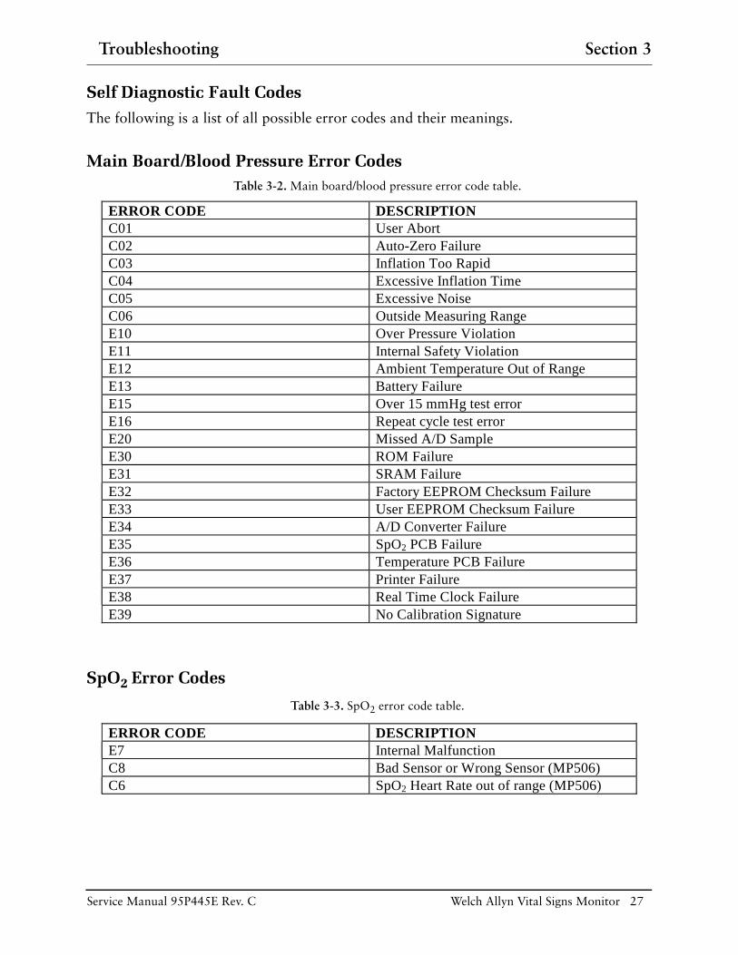
Self Diagnostic Fault CodesThe following is a list of all possible error codes and their meanings.
Main Board/Blood Pressure Error CodesTable 3-2. Main board/blood pressure error code table.
SpO2 Error Codes
Table 3-3. SpO2 error code table.
ERROR CODE DESCRIPTION C01 User Abort C02 Auto-Zero Failure C03 Inflation Too Rapid C04 Excessive Inflation Time C05 Excessive Noise C06 Outside Measuring Range E10 Over Pressure Violation E11 Internal Safety Violation E12 Ambient Temperature Out of Range E13 Battery Failure E15 Over 15 mmHg test error E16 Repeat cycle test error E20 Missed A/D Sample E30 ROM Failure E31 SRAM Failure E32 Factory EEPROM Checksum Failure E33 User EEPROM Checksum Failure E34 A/D Converter Failure E35 SpO2 PCB Failure E36 Temperature PCB Failure E37 Printer Failure E38 Real Time Clock Failure E39 No Calibration Signature
ERROR CODE DESCRIPTION E7 Internal Malfunction C8 Bad Sensor or Wrong Sensor (MP506) C6 SpO2 Heart Rate out of range (MP506)

28 Welch Allyn Vital Signs Monitor Service Manual 95P445E Rev. C
Section 3 Troubleshooting
Temperature Error CodesTable 3-4. Temperature error code table.
Temperature Error Code Correction1. Turn the unit off.
2. Hold down the "Start" button as you turn the unit back on. Continue to hold down the "Start" button until the alarm signals dissipate.
3. Once the software versions of the unit appear, press the “Review” button until three dashes (- - -) are seen in the Temperature window.
4. Once this has been confirmed, press the “Review” button until the software versions of the unit are seen once again in the appropriate windows.
5. Turn the unit off, and then turn the unit back on allowing it to boot up in the normal mode.
6. Remove the probe from the housing. You should see "188.8" then "ORL" appear. If this does not occur, please contact your local Welch Allyn Service Department.
ERROR CODE DESCRIPTION E0.1 Probe Heater Accumulator E0.2 Probe A/D Pulse Width Error E0.3 Adaptive Probe Gain too High or Low E1.1 Ambient temperature too high E1.2 Ambient temperature too low E2.1 Battery Low E3.1 RAM read/write error E3.2 ROM checksum error E3.3 CPU instruction error E4.0 PTB resistor A/D pulse width error E4.1 RatioCal resistor A/D pulse width error E4.2 External Ambient Thermistor A/D pulse width error E5.0 Heater Circuit error E5.1 Heater overheated error E5.2 Heater watch dog time out E6.0 PTB resistor “temperature” error E9.1 Communication Error C20 Broken Probe “P” Loss of Tissue Contact E12 Ambient temperature limit

Troubleshooting Section 3
Service Manual 95P445E Rev. C Welch Allyn Vital Signs Monitor 29
Complaint / Cause / Corrective Action
Table 3-5. General Guide to Problems and Corrective Actions.
Symptom Possible Causes Explanation and Corrective Action
Incorrect cuff size
Note: Use only Welch Allyn approved cuffs
Determine correct cuff size:
• Use reference marking on cuff.
• Measure patient’s arm circumference midway between the elbow and the shoulder. (See “Chart for Determining Cuff Size” in the Operation Manual, to select the correct cuff size.
Patients arm position Ensure patients arm is at heart level
Arm movement during blood pressure cycle
Keep arm still during blood pressure cycle:
• Movement may cause inaccuracies from artifact.
Blood pressure taken over clothing
Blood pressure should be taken on a bare arm.
1. Inaccurate blood pressure readings
Arrhythmia Check for regularity of heart rate:
(Palpate pulse or check with ECG monitor)
• Moderate to severe heart rate irregularities may make blood pressure difficult to measure.
Please Note:
Differences of up to 10mmHg is considered normal and will occur for a number of reasons including intrapatient BP variability, observer hearing differences, and ausultatory deflation rate.
Incorrect reference Use the correct Korotkoff sound to determine diastolic blood pressure.
Many listeners incorrectly equate diastolic blood pressure with the disappearance of sound only (Phase 5). The Welch Allyn Vital Signs Monitor was developed using the American Heart Association recommendations, which state that phase 5 be used unless sound continues to 0 mmHg, in which case the change in the quality of sound (phase 4) is to be used.
Deflate cuff no faster than 3 mmHg per second:
• One of the major sources of error in auscultatory blood pressure measurement is deflating the cuff too quickly. The American Heart Association recommends deflation no faster than 3 mmHg per second.
Only use a sphygmomanometer that is known to be in calibration:
• Blood pressure taken with an un-calibrated sphygmomanometer may be very inaccurate.
Change in blood pressure from auscultatory reading to Welch Allyn Vital Signs Monitor reading
Check blood pressure immediately prior to Welch Allyn Vital Signs Monitor reading.
Poor auscultatory sound recognition by observer
Use higher quality stethoscope. Have a different observer check patient’s blood pressure.

30 Welch Allyn Vital Signs Monitor Service Manual 95P445E Rev. C
Section 3 Troubleshooting
2. Cuff inflation & deflation with no blood pressure readings displayed (or error code in display)
Leak in pneumatic system Ensure all cuff attachments are tight.
Carefully check for tubing leaks in blood pressure cuff and tubing attachment to monitor.
Arm movement during cycle Keep arm still during blood pressure cycle.
•Movement may cause inaccuracies from artifact.
Tubing movement artifact Do not contact tubing during blood pressure cycle.
• Movement may cause inaccuracies from artifact
3. No cuff inflation Connections from monitor to cuff loose
Check all connections. (Do not over tighten).
4. Temperature Malfunction
Broken probe Replace probe.
Consult Technical Manual.
Notify Biomedical department or Welch Allyn Technical Support.
Wait for display window to read OrL before placing probe.
Improper probe placement Place probe in most posterior sublingual pocket.
Notify Biomedical department or Welch Allyn Technical Support.
Probe not replaced Replace probe in holder prior to taking another temperature.
5. SpO2 Malfunction Improperly attached sensor Insert the patient’s finger completely into sensor
• Sensor in place but no SpO2 on display
Cable incorrectly plugged into monitor.
Ensure sensor cable is correctly plugged into monitor.
• Inaccurate SpO2 reading
Sp02 disabled Ensure Sp02 is enabled. (check Configuration Mode)
Incorrect Sensor Ensure that correct manufacturers sensor is in used.
• Nellcor sensors are not interchangeable with NONIN sensors
6. Printer Malfunction Paper will not advance Consult Technical Manual.
Notify Biomedical department or Welch Allyn Technical Support.
7. Monitor will not turn on.
Low battery Check connections between monitor and transformer, and transformer and wall receptacle.
Monitor not powering up Unplug unit from wall receptacle and check for breaks in cord. If connections secure, check electrical outlet.
• Charging light will be on if connections are OK and the monitor is plugged into a working outlet
Notify Biomedical Department or Welch Allyn Technical Support.
Table 3-5. General Guide to Problems and Corrective Actions.
Symptom Possible Causes Explanation and Corrective Action
Troubleshooting Section 3
Service Manual 95P445E Rev. C Welch Allyn Vital Signs Monitor 31
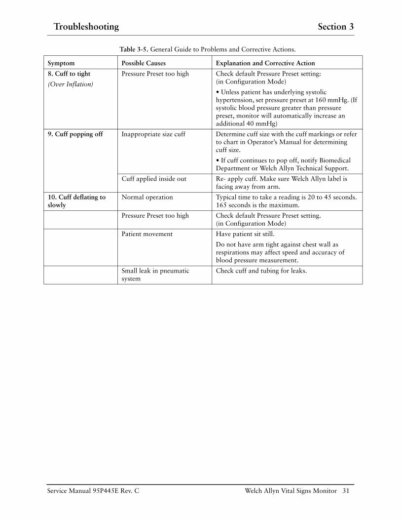
8. Cuff to tight
(Over Inflation)
Pressure Preset too high Check default Pressure Preset setting: (in Configuration Mode)
• Unless patient has underlying systolic hypertension, set pressure preset at 160 mmHg. (If systolic blood pressure greater than pressure preset, monitor will automatically increase an additional 40 mmHg)
9. Cuff popping off Inappropriate size cuff Determine cuff size with the cuff markings or refer to chart in Operator’s Manual for determining cuff size.
• If cuff continues to pop off, notify Biomedical Department or Welch Allyn Technical Support.
Cuff applied inside out Re- apply cuff. Make sure Welch Allyn label is facing away from arm.
10. Cuff deflating to slowly
Normal operation Typical time to take a reading is 20 to 45 seconds. 165 seconds is the maximum.
Pressure Preset too high Check default Pressure Preset setting. (in Configuration Mode)
Patient movement Have patient sit still.
Do not have arm tight against chest wall as respirations may affect speed and accuracy of blood pressure measurement.
Small leak in pneumatic system
Check cuff and tubing for leaks.
Table 3-5. General Guide to Problems and Corrective Actions.
Symptom Possible Causes Explanation and Corrective Action

32 Welch Allyn Vital Signs Monitor Service Manual 95P445E Rev. C
Section 3 Troubleshooting

Disassembly and Repair Section 4
Service Manual 95P445E Rev. C Welch Allyn Vital Signs Monitor 33
Front HousingNote: Opening up the front housing is necessary when replacing the main fuse. Complete removal of the front housing is necessary to replace the main printed circuit board (PCB), display board, switch pad and other components.
Preparing the unit for disassembly:
1. Turn unit off and disconnect AC power cord from the unit.
2. Disconnect all accessories from the unit. A. If the unit is pole mounted, remove unit from the pole. B. If the unit is wall mounted, remove unit from the wall. C. If the unit is free standing, turn the back towards you.
Battery cover removal:
3. Remove four (4) Phillips head screws from the battery door.
4. Remove battery door.
Battery removal from battery compartment:
5. Remove the battery out of the compartment by turning the unit upside down and shaking until battery begins to slide out.
6. Disconnect the two (2) connectors.
Note: If the battery is to be discarded, comply with all environmental regulations pertaining to battery disposal.
Opening front housing:
7. Position unit so the front panel is facing down.
8. Remove six (6) Phillips screws.
9. Carefully separate the front and rear housings.
Disconnection of connectors:
10. Disconnect the connector (red) from top of main board to relieve strain.
11. Unplug main 14-pin connector (red) from center of main PCB.
12. Disconnect pressure lines from transducers.
13. Disconnect the printer flex circuit from the main board.
14. Disconnect 7-pin connector coming from the temperature connector PCB to thetemperature PCB.
15. Disconnect the green wire 2-pin connector from the main board.

Section 4 Disassembly and Repair
34 Welch Allyn Vital Signs Monitor Service Manual 95P445E Rev. C
Note: The orientation of the green wire is towards the center of the main PCB, or away from the temperature board. 16. Disconnect the temperature PCB.
17. Remove the main PCB by removing the 7 torx screws with the torx t8 bit.
18. Disconnect the flex cable that connects to the display PCB.
19. Remove the main PCB.
20. Remove the 7 gray spacers.
21. Remove the display PCB from front housing.
Note: The front housing is now free.
Note: Replace the front housing by assembling in reverse order following these special instructions.
Reconnecting the connectors:
25. Reconnect the green wire 2-pin connector to the two male pins on the main board with the wire contact (away from) the temperature board.
26. Carefully align all other connectors and flex circuits in mating connectors.Reassemble in reverse order. No special techniques required.
Verification of repair:
27. Switch the unit to “on” and perform a full functional check.
Main PCB Note: Removing and replacing the main PCB requires that you remove the battery, split the cases, unplug one pneumatic line and electrical connectors. The small temperature board will be removed in the process. It can be swapped over to the replacement main PCB. It is held on by two of the seven torx fasteners.
1. Turn unit off and disconnect AC power cord from the unit.
2. Disconnect all accessories from the unit. A. If the unit is pole mounted, remove unit from the pole. B. If the unit is wall mounted, remove unit from the wall. C. If the unit is free standing, turn the back towards you.
Battery cover removal:
3. Remove four (4) Phillips head screws from the battery door with the Phillips bit.
4. Remove battery door.
Battery removal from battery compartment:

Disassembly and Repair Section 4
Service Manual 95P445E Rev. C Welch Allyn Vital Signs Monitor 35
5. Remove the battery out of the compartment by turning the unit upside down and shaking until battery begins to slide out.
6. Disconnect the two (2) connectors.
Note: If the battery is to be discarded, comply with all environmental regulations pertaining to battery disposal.
Opening front housing:
7. Position unit so the front panel is facing down.
8. Remove six (6) Phillips screws with the Phillips bit.
9. Carefully separate the front and rear housings.
Note: The orientation of the green wire is towards the center of the main PCB, or away from the temperature board.
Note: The front housing is now free of the rear housing.
Removal of temperature board from main PCB:
10. Unscrew two torx fasteners with the torx t8 bit, lift the temperature board up and re-move. 11. Separate the main PCB from the display PCB.
12. Unplug the main PCB to display PCB flex circuit.
13. Remove five (5) remaining torx fasteners with the torx t8 bit and lift the main PCB out of the front housing. Watch for the 7 gray spacers.
Note: Reassemble in reverse order with attention to the following details.
Attaching the temperature board to the main PCB:
14. Make sure all of the seven (7) gray plastic board spacers are in place before placing the main PCB over the display PCB.
15. Insert and tighten five of the last fasteners that were removed.
16. Place the temperature board onto the main PCB and secure it with two torx fasteners.
17. Reconnect the temperature board connector to the main PCB socket.
Note: Reassemble in reverse order.
Verification of repair:
18. When completely assembled, switch the unit to “on” and perform a full functional check, including recalibration.

Section 4 Disassembly and Repair
36 Welch Allyn Vital Signs Monitor Service Manual 95P445E Rev. C
DC to DC Converter (SpO2 Units Only)
Note: To replace the DC to DC converter, it is necessary to remove the main PCB.
Preparing the unit for disassembly:
1. Turn unit off and disconnect AC power cord from the unit.
2. Disconnect all accessories from the unit. A. If the unit is pole mounted, remove unit from the pole. B. If the unit is wall mounted, remove unit from the wall. C. If the unit is free standing, turn the back towards you.
Battery cover removal:
3. Remove four (4) Phillips head screws from the battery door with the #4 Phillips bit.
4. Remove battery door.
Battery removal from battery compartment:
5. Remove the battery out of the compartment by turning the unit upside down and shaking until battery begins to slide out.
6. Disconnect the two (2) connectors.
Note: If the battery is to be discarded, comply with all environmental regulations pertaining to battery disposal.
7. Opening front housing.
8. Position unit so the front panel is facing down.
9. Remove six (6) Phillips screws with the Phillips bit.
10. Carefully separate the front and rear housings.
Disconnection of connectors:
11. Disconnect the connector (red) from top of main board to relieve strain.
12. Unplug main 14-pin connector (red) from center of main PCB.
13. Disconnect pressure lines from transducers.
14. Disconnect the printer flex circuit from the main board.
15. Disconnect 7-pin connector coming from the temperature connector PCB to the temperature PCB.
16. Disconnect the green wire 2-pin connector from the main board.
Note: The orientation of the green wire is towards the center of the main PCB, or away from the temperature board.

Disassembly and Repair Section 4
Service Manual 95P445E Rev. C Welch Allyn Vital Signs Monitor 37
Note: The front housing is now free of the rear housing.
17. Separating the main PCB from the display PCB.
18. Unplug the main PCB to display PCB flex circuit.
19. Remove seven (7) torx fasteners with the torx t8 bit and lift the main PCB and the temperature PCB out of the front housing.
Replacing the DC to DC converter from the main PCB:
20. Peel off the rtv surrounding the old converter.
21. De-solder the old converter.
22. Clear the 8 holes out with a thru-hole solder sucker.
23. Install a replacement converter as per Figure 4-1 below.
24. Secure with rtv (innerbond i-45) on all four sides.
Figure 4-1. DC to DC replacement.
Note: Reassemble in reverse order, no special techniques required.
Verification of repair:
25. When completely assembled, switch the unit to “on” and perform a full functional check, including recalibration.

Section 4 Disassembly and Repair
38 Welch Allyn Vital Signs Monitor Service Manual 95P445E Rev. C
Pressure Transducers on Main PCBNote: To replace the pressure transducer on the main PCB, it is necessary to remove the main PCB.
1. Turn unit off and disconnect AC power cord from the unit.
2. Disconnect all accessories from the unit. A. If the unit is pole mounted, remove unit from the pole. B. If the unit is wall mounted, remove unit from the wall. C. If the unit is free standing, turn the back towards you.
Battery cover removal:
3. Remove four (4) Phillips head screws from the battery door with the Phillips bit.
4. Remove battery door.
Battery removal from battery compartment:
5. Remove the battery out of the compartment by turning the unit upside down and shaking until battery begins to slide out.
6. Disconnect the two (2) connectors.
Note: If the battery is to be discarded, comply with all environmental regulations pertaining to battery disposal.
Opening front housing:
7. Position unit so the front panel is facing down.
8. Remove six (6) Phillips screws with the Phillips bit.
9. Carefully separate the front and rear housings.
Disconnection of connectors:
10. Disconnect the connector (red) from top of main board to relieve strain.
11. Unplug main 14-pin connector (red) from center of main PCB.
12. Disconnect pressure line from transducers.
13. Disconnect the printer flex circuit from the main board.
14. Disconnect 7-pin connector coming from the temperature connector PCB to the temperature PCB.
15. Disconnect the green wire 2-pin connector from the main board.
Note: The orientation of the green wire is towards the center of the main PCB, or away from the temperature board.

Disassembly and Repair Section 4
Service Manual 95P445E Rev. C Welch Allyn Vital Signs Monitor 39
Note: The front housing is now free of the rear housing. 16. Separating the main PCB from the display PCB.
17. Unplug the main PCB to display PCB flex circuit.
18. Remove seven (7) torx fasteners with the torx t8 bit and lift the main PCB and the temperature PCB out of the front housing.
19. Do not lose the 7 gray spacers.
Replacing the pressure transducer on the main PCB:
20. De-solder the old transducer.
21. Clear the 6 holes out with a thru-hole solder sucker.
22. Install a replacement pressure transducer per Figure 4-2.
Figure 4-2. Pressure transducer replacement.
Note: Reassemble in reverse order, no special techniques required.
Verification of repair:
23. When completely assembled, switch the unit to “on” and perform a full functional check, including recalibration.
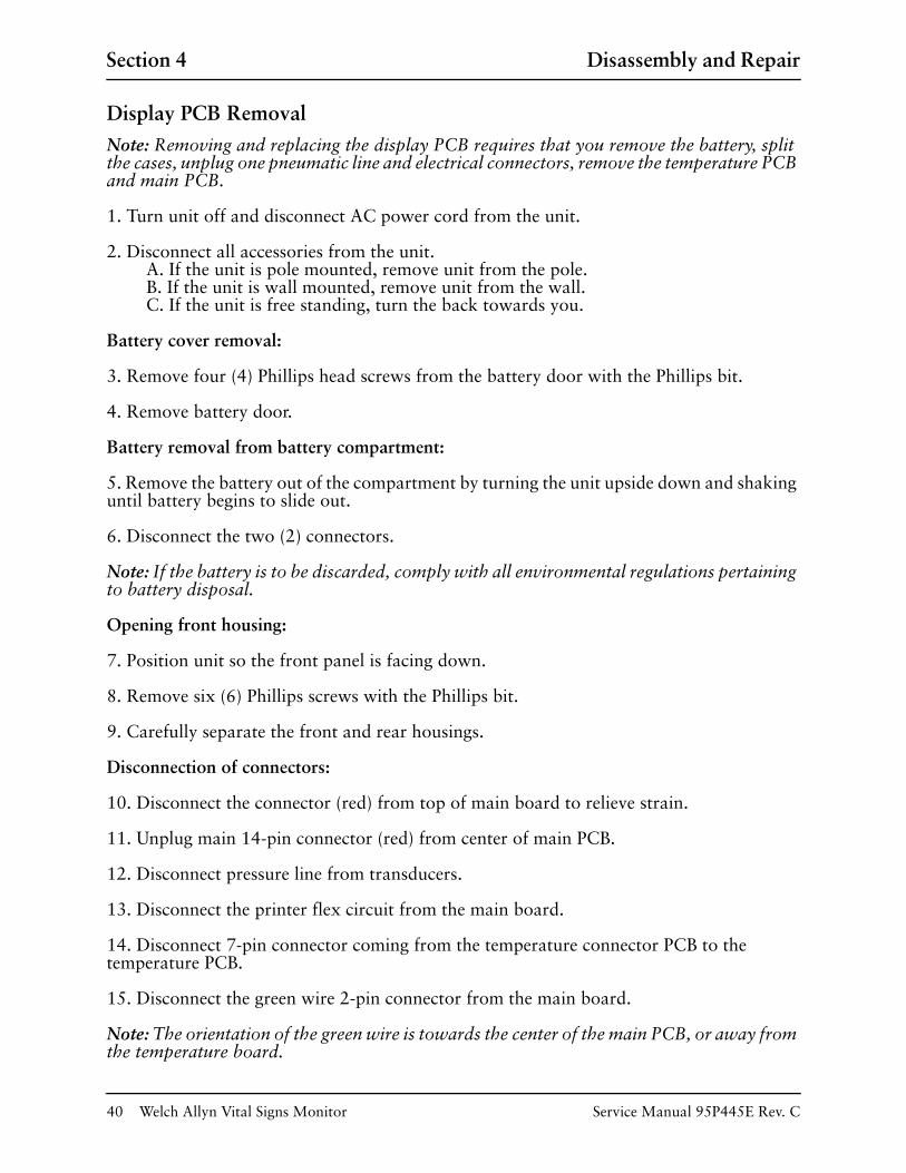
Section 4 Disassembly and Repair
40 Welch Allyn Vital Signs Monitor Service Manual 95P445E Rev. C
Display PCB RemovalNote: Removing and replacing the display PCB requires that you remove the battery, split the cases, unplug one pneumatic line and electrical connectors, remove the temperature PCB and main PCB.
1. Turn unit off and disconnect AC power cord from the unit.
2. Disconnect all accessories from the unit. A. If the unit is pole mounted, remove unit from the pole. B. If the unit is wall mounted, remove unit from the wall. C. If the unit is free standing, turn the back towards you.
Battery cover removal:
3. Remove four (4) Phillips head screws from the battery door with the Phillips bit.
4. Remove battery door.
Battery removal from battery compartment:
5. Remove the battery out of the compartment by turning the unit upside down and shaking until battery begins to slide out.
6. Disconnect the two (2) connectors.
Note: If the battery is to be discarded, comply with all environmental regulations pertaining to battery disposal.
Opening front housing:
7. Position unit so the front panel is facing down.
8. Remove six (6) Phillips screws with the Phillips bit.
9. Carefully separate the front and rear housings.
Disconnection of connectors:
10. Disconnect the connector (red) from top of main board to relieve strain.
11. Unplug main 14-pin connector (red) from center of main PCB.
12. Disconnect pressure line from transducers.
13. Disconnect the printer flex circuit from the main board.
14. Disconnect 7-pin connector coming from the temperature connector PCB to the temperature PCB.
15. Disconnect the green wire 2-pin connector from the main board.
Note: The orientation of the green wire is towards the center of the main PCB, or away from the temperature board.

Disassembly and Repair Section 4
Service Manual 95P445E Rev. C Welch Allyn Vital Signs Monitor 41
Note: The front housing is now free of the rear housing. Separating the main PCB from the display PCB:
16. Unplug the main PCB to display PCB flex circuit.
17. Remove seven (7) torx fasteners with the torx t8 bit and lift the main PCB and the temperature PCB out of the front housing.
18. Remove the seven (7) gray board spacers as they will be reused.
19. Removing the display PCB from the front housing.
20. Gently lift the display board out of the front housing. Be careful not to damage the exposed LED's.
Note: Reassemble in reverse order with attention to the following details.
21. Place display PCB into front housing.
22. Seat the display PCB over screw bosses.
23. Place 7 spacers over front housing bosses projecting through PCB and seat them securely against the surface of the PCB.
Attaching main PCB to the display PCB and front housing:
Note: Use all seven gray spacers to prevent damage to the boards.
24. Gently lay the main PCB onto the spacers (component side up) so that all of the holes line up.
25. Insert and tighten five (5) torx fasteners with the torx t8 bit.
Attaching the temperature board (option):
26. Align the temperature board so that the component side faces towards the center of the unit.
Note: Continue reassembly in reverse order of disassembly.
Verification of repair:
27. When completely assembled, switch the unit to “on” and perform a full functional check, including recalibration.

Section 4 Disassembly and Repair
42 Welch Allyn Vital Signs Monitor Service Manual 95P445E Rev. C
Key Pad (Switch Array)Note: Removing and replacing the key pad requires that you remove the battery, split the cases, unplug one pneumatic line and electrical connectors, and remove the main and display PCB's from the front housing. If the key pad is being removed for suspected moisture or contamination, replace it with a new one once the PCB is cleaned.
1. Turn unit off and disconnect AC power cord from the unit. 2. Disconnect all accessories from the unit. A. If the unit is pole mounted, remove unit from the pole. B. If the unit is wall mounted, remove unit from the wall. C. If the unit is free standing, turn the back towards you.
Battery cover removal:
3. Remove four (4) Phillips head screws from the battery door with the Phillips bit.
4. Remove battery door.
Battery removal from battery compartment:
5. Remove the battery out of the compartment by turning the unit upside down and shaking until battery begins to slide out.
6. Disconnect the two (2) connectors.
Note: If the battery is to be discarded, comply with all environmental regulations pertaining to battery disposal.
Opening front housing:
7. Position unit so the front panel is facing down.
8. Remove six (6) Phillips screws with the Phillips bit.
9. Carefully separate the front and rear housings.
Disconnection of connectors:
10. Disconnect the connector (red) from top of main board to relieve strain.
11. Unplug main 14-pin connector (red) from center of main PCB.
12. Disconnect pressure line from transducers.
13. Disconnect the printer flex circuit from the main board.
14. Disconnect 7-pin connector coming from the temperature connector PCB to the temperature PCB.
15. Disconnect the green wire 2-pin connector from the main board.

Disassembly and Repair Section 4
Service Manual 95P445E Rev. C Welch Allyn Vital Signs Monitor 43
Note The orientation of the green wire is towards the center of the main PCB, or away from the temperature board. Note: The front housing is now free of the rear housing.
16. Separating the main PCB from the display PCB.
17. Unplug the main PCB to display PCB flex circuit.
18. Remove all seven (7) torx fasteners with the torx t8 bit and lift the main PCB and temperature PCB out of the front housing.
19. Remove the seven (7) gray board spacers as they will be reused.
Removing the display PCB from the front housing:
20. Gently lift the display board out of the front housing. Be careful not to damage the exposed led's.
Removing the key pad:
21. Gently peel the old key pad away from the PCB.
22. Inspect the PCB for contamination and clean accordingly with alcohol. Allow the alcohol to evaporate for one minute then blow off lint. From this point on, do not touch contact surfaces.
Note: Reassemble in reverse order with attention to the following details.
23. Attach new key pad to the display PCB.
24. Lay flexible key pad over PCB and exactly align protrusions over holes in PCB.
25. Press protrusions into holes with tool. Be careful not to tear keypad.
26. Place display PCB into front housing.
27. Seat the display PCB over screw bosses.
28. Place 7 spacers over front housing bosses projecting through PCB and seat them securely against the surface of the PCB.
Attaching main PCB to the display PCB and front housing:
Note: Use all seven gray spacers to prevent damage to the boards.
29. Gently lay the main PCB onto the spacers (component side up) so that all of the holes line up.
30. Insert and tighten torx fasteners with the torx t8 bit.
Attaching the temperature board (option):
31. Align the temperature board so that the component side faces towards the center of the unit.

Section 4 Disassembly and Repair
44 Welch Allyn Vital Signs Monitor Service Manual 95P445E Rev. C
Note: Continue reassembly in reverse order of disassembly.
Verification of repair:
32. When completely assembled, switch the unit to “on” and perform a full functional check, including recalibration.
Temperature PCBNote: Removing and replacing the Temperature PCB requires that you remove the battery, split the cases, unplug one pneumatic line and electrical connectors. The small temperature board can be removed by unscrewing two Phillips head screws, which hold the board to the two small "l" brackets. It is not necessary to remove the brackets from the main PCB.
1. Turn unit off and disconnect AC power cord from the unit.
2. Disconnect all accessories from the unit. A. If the unit is pole mounted, remove unit from the pole. B. If the unit is wall mounted, remove unit from the wall. C. If the unit is free standing, turn the back towards you.
Battery cover removal:
3. Remove four (4) Phillips head screws from the battery door with the Phillips bit.
4. Remove battery door.
Battery removal from battery compartment:
5. Remove the battery out of the compartment by turning the unit upside down and shaking until battery begins to slide out.
6. Disconnect the two (2) connectors.
Note: If the battery is to be discarded, comply with all environmental regulations pertaining to battery disposal.
Opening front housing:
7. Position unit so the front panel is facing down.
8. Remove six (6) Phillips screws with the Phillips bit.
9. Carefully separate the front and rear housings.
Disconnection of connectors:
10. Disconnect the connector (red) from top of main board to relieve strain. 11. Unplug main 14-pin connector (red) from center of main PCB.
12. Disconnect pressure line from transducers.
13. Disconnect the printer flex circuit from the main board.

Disassembly and Repair Section 4
Service Manual 95P445E Rev. C Welch Allyn Vital Signs Monitor 45
14. Disconnect 7-pin connector coming from the temperature connector PCB to the temperature PCB.
15. Disconnect the green wire 2-pin connector from the main board.
Note: The orientation of the green wire is towards the center of the main PCB, or away from the temperature board. Note: The front housing is now free from the rear housing.
Removal of temperature board from "l" brackets on the main PCB:
16. Disconnect connector from main board socket.
17. Disconnect the temperature connector cable from the temperature PCB.
18. Unscrew two torx fasteners with the torx t8 bit and lift the temperature board up.
Note: The temperature board is now free from the main PCB.
Note: Reassemble in reverse order with attention to the following details.
Attaching the temperature board when main PCB was not removed:
19. Place a spacer on each Phillips head screw.
20. Insert screw through board.
21. Place another spacer on each screw.
22. Thread screw into "l" bracket part way.
23. Apply Locktite 222 on the end of the screw and thread all the way into the bracket.
24. Reconnect the temperature connector to main PCB socket.
25. Reconnect the temperature connector cable to the temperature PCB.
Note: Reassemble in reverse order.
Verification of repair:
26. When completely assembled, switch the unit to “on” and perform a full functional check of the temperature function.

Section 4 Disassembly and Repair
46 Welch Allyn Vital Signs Monitor Service Manual 95P445E Rev. C
Specific Oxygen Board (Nonin SpO2 PCB)
Note: Removing and replacing the Nonin SpO2 PCB requires that you remove the battery, and remove the front housing.
1. Turn unit off and disconnect AC power cord from the unit.
2. Disconnect all accessories from the unit. A. If the unit is pole mounted, remove unit from the pole. B. If the unit is wall mounted, remove unit from the wall. C. If the unit is free standing, turn the back towards you.
Battery cover removal:
3. Remove four (4) Phillips head screws from the battery door with the Phillips bit.
4. Remove battery door.
Battery removal from battery compartment:
5. Remove the battery out of the compartment by turning the unit upside down and shaking until battery begins to slide out.
6. Disconnect the two (2) connectors.
Note: If the battery is to be discarded, comply with all environmental regulations pertaining to battery disposal.
Opening front housing:
7. Position unit so the front panel is facing down.
8. Remove six (6) Phillips screws with the Phillips bit.
9. Carefully separate the front and rear housings.
Disconnection of connectors:
10. Disconnect the connector (red) from top of main board to relieve strain.
11. Unplug main 14-pin connector (red) from center of main PCB.
12. Disconnect pressure line from transducers.
13. Disconnect the printer flex circuit from the main board.
14. Disconnect 7-pin connector coming from the temperature connector PCB to the temperature PCB.
15. Disconnect the green wire 2-pin connector from the main board.
Note: The orientation of the green wire is towards the center of the main PCB, or away from the temperature board.

Disassembly and Repair Section 4
Service Manual 95P445E Rev. C Welch Allyn Vital Signs Monitor 47
Note: The front housing is now free from the rear housing. Removing the Nonin SpO2 PCB:
16. Turn unit on its back and unscrew two torx screws from the board with the torx t8 bit.
17. Disconnect tube from bottom of valve.
18. Disconnect tube from pressure outlet fitting.
19. Slide board out of well.
20. Remove wires from board.
21. Remove rtv from the back side of seven wire solder connections as shown in Figure 4-3.
22. Unsolder wires from board as per Figure 4-3.
23. Remove solder from wires to prepare for new board.
Figure 4-3. RTV removal from NONIN SpO2 PCB.
Checking wire connections by pin-out process:
Note: Each wire will terminate at a specific pin position on the SpO2 jack. Therefore, reconfirm that all connections are correct by pinning out your work. Use Figure 4-4 to verify connections.
Figure 4-4. SpO2 jack, wire side.

Section 4 Disassembly and Repair
48 Welch Allyn Vital Signs Monitor Service Manual 95P445E Rev. C
Replacing the SpO2 board:
24. Connect wires to locations as shown in Figure 4-4. 25. Cover bottoms of connections with 376e108 (G.E. gray rtv #167, electronic adhesivesealant)
Note: Reassemble in reverse order of disassembly.
Verification of repair:
26. When completely assembled, switch the unit to “on” and perform a full functional check of the SpO2 function.
Specific Oxygen Board (Nellcor SpO2 PCB - MP205 or MP506)
Note: Removing and replacing the Nellcor SpO2 PCB requires that you remove the battery, and remove the front housing.
1. Turn unit off and disconnect AC power cord from the unit.
2. Disconnect all accessories from the unit. A.If the unit is pole-mounted, remove unit from the pole. B. If the unit is wall-mounted, remove unit from the wall. C. If the unit is free-standing, turn the back towards you.
Battery cover removal:
3. Remove four (4) Phillips head screws from the battery door with the Phillips bit.
4. Remove battery door.
Battery removal from battery compartment:
5. Remove the battery out of the compartment by turning the unit upside down and shaking until battery begins to slide out.
6. Disconnect the two (2) connectors.
Note: If the battery is to be discarded, comply with all environmental regulations pertaining to battery disposal.
Opening front housing:
7. Position unit so the front panel is facing down.
8. Remove six (6) Phillips screws with the Phillips bit.
9. Carefully separate the front and rear housings.
Disconnection of connectors:
10. Disconnect the connector from top of main board to relieve strain.

Disassembly and Repair Section 4
Service Manual 95P445E Rev. C Welch Allyn Vital Signs Monitor 49
11. Unplug main 14-pin connector (red) from center of main PCB.
12. Disconnect pressure lines from transducers.
13. Disconnect 7-pin connector coming from the temperature connector PCB to the temperature PCB.
14. Disconnect the green wire 2-pin connector from the main board.
Note: The orientation of the green wire is towards the center of the main PCB, or away from the temperature board.
Note: The front housing is now free from the rear housing. Removing the Nellcor SpO2 PCB:
15. Turn unit on its back and unscrew two torx screws (Use the torx T8 bit) from the board and lift blue wire.
16. Disconnect tube from bottom of valve.
17. Disconnect tube from pressure outlet fitting.
18. Remove two (2) screws from valve and lift valve,using the torx T8 bit.
19. Lift Nellcor SpO2 PCB from well.
20. Removing wires from board.
21. Unplug the connector for the main PCB terminator by using a flat head screw driver and gently pry upwards on the connector.
22. Unplug the connector for the outside interface by simply pulling back on the connector.
Note: The SpO2 PCB has been removed from the rear housing.
Replacing the SpO2 PCB:
23. Connect the main PCB terminator cable connector to its proper port on the Nellcor SpO2 PCB.
24. Connect the outside interface cable connector to its proper port on the Nellcor SpO2 PCB.
Note: Reassemble in reverse order of disassembly.
Verification of repair:
25. When completely assembled, switch the unit to “on” and perform a full functional check of the SpO2 function.

Section 4 Disassembly and Repair
50 Welch Allyn Vital Signs Monitor Service Manual 95P445E Rev. C
Pump/Motor AssemblyNote: Removing and replacing the pump motor assembly requires the removal of the battery and the front housing. The replacement motor comes with an attached wire tie mounting pad.
1. Turn unit off and disconnect AC power cord from the unit.
2. Disconnect all accessories from the unit. A. If the unit is pole mounted, remove unit from the pole. B. If the unit is wall mounted, remove unit from the wall. C. If the unit is free standing, turn the back towards you.
Battery cover removal:
3. Remove four (4) Phillips head screws from the battery door using the Phillips bit.
4. Remove battery door.
Battery removal from battery compartment:
5. Remove the battery out of the compartment by turning the unit upside down and shaking until battery begins to slide out.
6. Disconnect the two (2) connectors.
Note: If the battery is to be discarded, comply with all environmental regulations pertaining to battery disposal.
Opening front housing:
7. Position unit so the front panel is facing down.
8. Remove six (6) Phillips screws with using the Phillips bit. 9. Carefully separate the front and rear housings.
Disconnection of connectors
10. Disconnect the connector (red) from top of main board to relieve strain.
11. Unplug main 14-pin connector (red) from center of main PCB.
12. Disconnect pressure lines from transducers.
13. Disconnect the printer flex circuit from the main board.
14. Disconnect 7-pin connector coming from the temperature connector PCB to the temperature PCB.
15. Disconnect the green wire 2-pin connector from the main board.
Note: The orientation of the green wire is towards the center of the main PCB, or away from the temperature board.

Disassembly and Repair Section 4
Service Manual 95P445E Rev. C Welch Allyn Vital Signs Monitor 51
Note: The front housing is now free of the rear housing. Removing the old pump/motor:
16. Remove the tubing from the motor. This can also be done after the motor is more accessible when it is out of the rear housing.
17. Place a flat blade screwdriver under the wire tie pad which holds motor in place.
18. Gently remove the motor from the rear housing.
19. Unsolder the orange and white wires from the motor terminals.
20. Remove any residue from the old pad with a flat blade screwdriver.
Installing a replacement pump/motor assembly:
21. Clean the pad mounting area with alcohol prior to soldering. This will allow time for the alcohol to evaporate.
22. Solder the orange wire to the plus (+) terminal of the motor.
23. Solder the white wire to the negative (-) terminal of the motor.
Caution! Be careful in this next step. Do not attach the pump/motor assembly to the rear housing until you are sure it is positioned properly. Keep in mind that the wires are intended to be on the left side of the pump/motor assembly, and that the motor end must not be resting against the back wall of the rear housing.
24. Remove the protective paper from the pad and place the pump motor assembly into the rear housing so that the end of the pump is even with the platform it sits on. This assures that the motor end will not be in contact with the back wall of the rear housing. Be careful to keep the wires away from the adhesive pad. Make sure that the other wires in the area are on the left side of the motor.
25. When everything is aligned, attach the pump/motor assembly to the rear housing bypressing the adhesive pad against the platform.
26. Connect the tube to the barb fitting of the pump.
Note: Reassemble in reverse order of disassembly.
Verification of repair:
27. When completely assembled, switch the unit to “on” and perform a full functional check and recalibration.

Section 4 Disassembly and Repair
52 Welch Allyn Vital Signs Monitor Service Manual 95P445E Rev. C
Valve (Pneutronics)Note: Removing and replacing the Pneutronics valve requires the removal of the battery and the front housing. The replacement valve attaches with two torx fasteners. Two spade connectors make up the electrical connections. One tube connects to the valve.
1. Turn unit off and disconnect AC power cord from the unit.
2. Disconnect all accessories from the unit. A. If the unit is pole mounted, remove unit from the pole. B. If the unit is wall mounted, remove unit from the wall. C. If the unit is free standing, turn the back towards you.
Battery cover removal:
3. Remove four (4) Phillips head screws from the battery door using the Phillips bit.
4. Remove battery door.
Battery removal from battery compartment:
5. Remove the battery out of the compartment by turning the unit upside down and shaking until battery begins to slide out.
6. Disconnect the two (2) connectors.
Note: If the battery is to be discarded, comply with all environmental regulations pertaining to battery disposal.
Opening front housing:
7. Position unit so the front panel is facing down.
8. Remove six (6) Phillips screws using the Phillips bit.
9. Carefully separate the front and rear housings.
Disconnection of connectors:
10. Disconnect the connector (red) from top of main board to relieve strain.
11. Unplug main 14-pin connector (red) from center of main PCB.
12. Disconnect pressure lines from transducers.
13. Disconnect the printer flex circuit from the main board.
14. Disconnect 7-pin connector coming from the temperature connector PCB to the temperature PCB.
15. Disconnect the green wire 2-pin connector from the main board.
Note: The orientation of the green wire is towards the center of the main PCB, or away from the temperature board.

Disassembly and Repair Section 4
Service Manual 95P445E Rev. C Welch Allyn Vital Signs Monitor 53
Note: The front housing is now free of the rear housing.
Removing the valve:
16. Remove the tubing from the valve.
17. Unscrew two torx fasteners. Use the t8 torx bit.
18. Gently remove the valve from the rear housing.
19. Disconnect the two spade connectors from the valve.
Installing a replacement valve: See figure 4-5.
20. Connect the green wire spade connector to the left terminal.
21. Connect the dark brown wire spade connector to the right terminal.
22. Replace two torx fasteners using a torx t8 bit.
23. Connect the tube to the barb connector of the valve.
Figure 4-5. Bottom view of valve (Pneutronics).
24. Reassemble in reverse order with attention to the following details.
Placement of wires during reassembly:
25. Make sure the four pin wire harness is routed over and around the valve, and not underneath it.
26. Make sure that no wires are pinched underneath the valve.
27. Make sure that the dark brown and green wires are pushed down into the housing to eliminate any interference with the gears of the printer.
Verification of repair:
28. When completely assembled, switch the unit to “on” and perform a full functional check and re-calibration.

Section 4 Disassembly and Repair
54 Welch Allyn Vital Signs Monitor Service Manual 95P445E Rev. C
Printer/Printer PCB/KeypadNote: Removing and replacing the printer /PCB assembly requires the removal of the battery and the front housing. The keypad array can cleaned and or replaced easily without removing the front housing. The printer and the printer PCB are soldered together and are replaced as a unit.
1. Turn unit off and disconnect AC power cord from the unit.
2. Disconnect all accessories from the unit. A. If the unit is pole mounted, remove unit from the pole. B. If the unit is wall mounted, remove unit from the wall. C. If the unit is free standing, turn the back towards you.
Battery cover removal:
3. Remove four (4) Phillips head screws from the battery door using the Phillips bit.
4. Remove battery door.
Battery removal from battery compartment:
5. Remove the battery out of the compartment by turning the unit upside down and shaking until battery begins to slide out.
6. Disconnect the two (2) connectors.
Note: If the battery is to be discarded, comply with all environmental regulations pertaining to battery disposal.
Opening front housing:
7. Position unit so the front panel is facing down.
8. Remove six (6) Phillips screws using the Phillips bit.
9. Carefully separate the front and rear housings.
Disconnection of connectors:
10. Disconnect the connector (red) from top of main board to relieve strain.
11. Unplug main 14-pin connector (red) from center of main PCB.
12. Disconnect pressure lines from transducers.
13. Disconnect the printer flex circuit from the main board.
14. Disconnect 7-pin connector coming from the temperature connector PCB to the temperature PCB.
15. Disconnect the green wire 2-pin connector from the main board.
Note: The orientation of the green wire is towards the center of the main PCB, or away from the temperature board.

Disassembly and Repair Section 4
Service Manual 95P445E Rev. C Welch Allyn Vital Signs Monitor 55
Note: The front housing is now free of the rear housing. Remove/clean keypad array:
16. Remove the paper cover.
17. Remove the paper roll.
18. Unscrew two torx fasteners using the t8 torx bit.
19. Gently slide the printer housing cover towards you and disengage the two screw tabsfrom the rear housing.
20. Very gently roll the printer housing cover up and away from you to gain access to the flex circuits underneath.
21. Disconnect the white flex circuit connector.
Note: The orientation of the blue color on the connector end of the flex circuit is facing away from you in while you are disconnecting and reconnecting later during reassembly.
22. Carefully unscrew the five (5) torx fasteners with insulators using the torx t8 bit. Be careful not to tear the copper shield from its connecting wire.
23. Lift up the copper shield and remove the keypad array.
Removing the printer /PCB assembly:
24. Insert a flat blade screwdriver under the printer and pry loose the two doublesided foam tape fasteners.
25. Slide the printer out of the rear housing.
26. Pass the printed circuit board through the opening in the rear housing and completely remove the printer and printer PCB assembly.
Note: Reassemble in reverse order with attention to the following details.
Placement of printer in rear housing:
27. When attaching the printer to the rear housing, make sure it is positioned all the way into the recess.
Attaching printer PCB to printer cover:
28. Carefully place the PCB into the cover so that the buttons protrude through the cover. Align the holes in the board with the standoffs on the cover and insert the five (5) screws with plastic insulators.
Verification of repair:
29. When completely assembled, switch the unit to 'on' and perform a full functional check of printer. Re-calibrate.
Section 4 Disassembly and Repair
56 Welch Allyn Vital Signs Monitor Service Manual 95P445E Rev. C
Battery Placement1. Lay unit face down on the test bench
2. Remove the (4) Phillips head screws holding the battery cover/handle to the unit using the Phillips bit.
3. Lift cover and remove.
4. Lift battery from housing and disconnect the connectors.
Note: Reassemble in reverse order.

Repair Parts Appendix A
Service Manual 95P445E Rev. C Welch Allyn Vital Signs Monitor 57
Vital Signs Monitor Repair Parts List
Part # Description Quantity106100-5 PHPS 6-32 X .250 3
10P1091 SPACER,PVC,SELF RETAINING 7
113P463 CABLE TIE MOUNT 1
113P464 CABLE TIE, 6 INCH 1
113P480-1 WIRE TIE, 4.0 LONG 1
113P490-1 CLIP,WIRE 1
113P495 SHIELD,MAIN,VSM 1
113S459 CONN,DC POWER JACK,2.5MM 1
113S497 KEY,TEMP PROBE CALIB. 1
114S583 ASSEMBLY,BATTERY,VSM 1
114S586 FUSE,5 AMP,20MM SIZE 1
117S144 DC/DC CONVERTER,5 VOLT 1
125S209A ASSY,VSM PRINTER BRD 1
125S227 ASSY,VSM,MAIN BRD (Main PCB and software) 1
125S230 ASSY,678 PCB WITH BRACKETS 1
125S231 ASSY,678 TEMP BOARD,(DIATEK) 1
125S232A ASSY,DISP PWA W/TEMP LEDS 1
125S232B ASSY,DISP PWA W/O TEMP LEDS 1
125S233 ASSY,TEMP CONN.BOARD,VSM 1
130S14 KIT,REPAIR,BATTERY PLATE 1
130S18 KIT,REPAIR,PRINTER HSG. 1
130S20 OBS.-KIT,REPAIR,NONIN SPO2 PCB 1
130S29E S/W,VSM REPAIR,ORDER NO. 1
130S4 KIT,REPAIR,DISPLAY ASSY. 1
130S41 KIT,VSM REPAIR,TUBING ASSEMBLY 1
130S45 KIT,VSM REPAIR,MAIN BOARD (Main PCB, Hardware and software) 1
130S48 KIT,VSM REPAIR,RS232 1
130S5 KIT,REPAIR,VALVE 1
130S50 KIT,VSM REPAIR,NELL CBL MP205 1
130S52 KIT,VSM REPAIR,678 TEMP PCB 1
130S53 KIT,VSM REPAIR,678 TEMP C.B. 1
130S58 KIT, MOUNTING PLATE 1
130S59 KIT, LUG & SCREW 1
130S6 KIT,REPAIR,PNEUMATIC CONN 1
130S64E KIT,5.17 S/W UPGRADE 1
14P1730 BRACKET,TEMP BOOT 1
14P1734 BRACKET, NELLCOR 1

58 Welch Allyn Vital Signs Monitor Service Manual 95P445E Rev. C
Appendix A Repair Parts
Part # Description Quantity168S103 KIT,ASSEMBLY,PUMP 1
22P1451 WASHER,FLAT,#4 NYLON 5
22P1451-2 WASHER,#6 FLAT NYLON 3
22P1451-3 WASHER,FLAT,NYLON,.098 X.187 2
22P1456 WASHER,FLAT,.33X.62X.049 1
22P1462 LOCKWASHER,#2 INT TOOTH 1
265E424-1 WIRE CUT TO 1" STRIPPD TO 1/4" 1
29P483 FAIR-RITE BEAD,ROUND WIRE 1
29P486 INSULATION,PCB 1
29P487 INSULATION 1
32P810 NUT,HEX,5/16-32X.095 1
35P1359 HOUSING, REAR 1
35P1360 HOUSING,PRINTER WELL 1
35P1361 HOUSING,THERMOMETER,CBP 1
35P1386 REAR HOUSING MODIFICATION,VSM 1
35P1395 HOUSING, VSM FRONT (MACHINED) 1
421007-1 TRANSFORMER,DOMESTIC,120V 1
421051-10 TUBING,1/8 X 1/4 X 1.15 1
421051-11 TUBING,1/8 X 1/4 X 1.50 1
421051-12 TUBING,1/8 X 1/4 X 2.50 1
421051-9 TUBING,1/8 X 1/4 X 0.95 1
421052-2 TUBING,1/16 X 3/16 X 3.80 1
421052-3 TUBING,1/16 X 3/16 X 4.00 1
421063-502 BOX SET, SPOT 1
43P820 GROMMET,PANEL,.312 ID,BLK 1
45P3286A LABEL,CONNECTOR,BP 1
45P3286B LABEL,CONNECTOR,BP/SPO2 1
45P3286C LABEL,CONNECTOR,BP/TEMP 1
45P3286D LABEL,CONN,BP/TEMP/SPO2 1
45P3294 LABEL,PRINTER PAPER 1
45P3296 SHIELD,ESD,PRINTER 1
45P3320 LABEL,SUB,WHITE,FRONT PANEL 1
45P3321 LABEL,SUB,WHITE,CONNECTOR 1
45P3328-2 LABEL,NELLCOR SENSOR 1
45P3343EA LABEL,FRONT PANEL,BP,ENGLISH 1
45P3343EB LABEL,FRT.PANL.BP,SPO2,ENGLISH 1
45P3343EC LABEL,FRT.PANL.BP,TEMP,ENGLISH 1
45P3343ED LABEL,FRONT PANEL,VSM,ENGLISH 1
45P3343FA LABEL,FRONT PANEL,BP,FRENCH 1

Repair Parts Appendix A
Service Manual 95P445E Rev. C Welch Allyn Vital Signs Monitor 59
Part # Description Quantity45P3343FB LABEL,FRT.PANL.BP,SPO2,FRENCH 1
45P3343FC LABEL,FRT.PANL.BP,TEMP,FRENCH 1
45P3343FD LABEL,FRONT PANEL,VSM,FRENCH 1
45P3343GA LABEL,FRONT PANEL,BP,GERMAN 1
45P3343GB LABEL,FRT.PANL.BP,SPO2,GERMAN 1
45P3343GC LABEL,FRT.PANL.BP,TEMP,GERMAN 1
45P3343GD LABEL,FRONT PANEL,VSM,GERMAN 1
45P3343IA LABEL,FRONT PANEL,BP,ITALIAN 1
45P3343IB LABEL,FRT.PANL.BP,SPO2,ITALIAN 1
45P3343IC LABEL,FRT.PANL.BP,TEMP,ITALIAN 1
45P3343ID LABEL,FRONT PANEL,VSM,ITALIAN 1
45P3343SA LABEL,FRONT PANEL,BP,SPANISH 1
45P3343SB LABEL,FRT.PANL.BP,SPO2,SPANISH 1
45P3343SC LABEL,FRT.PANL.BP,TEMP,SPANISH 1
45P3343SD LABEL,FRONT PANEL,VSM,SPANISH 1
45P3345E LABEL,ERROR CODE,LEFT,VSM 1
45P3345F LABEL,ERROR CODE,LEFT, VSM 1
45P3345G LABEL,ERROR CODE,LEFT,VSM 1
45P3345I LABEL,ERROR CODE,LEFT,VSM 1
45P3345S LABEL,ERROR CODE,LEFT,VSM 1
45P3347E LABEL,BUTTON,ENGLISH 1
45P3347F LABEL,BUTTON,FRENCH 1
45P3347G LABEL,BUTTON,GERMAN 1
45P3347I LABEL,BUTTON,ITALIAN 1
45P3347S LABEL,BUTTON,SPANISH 1
45P3348 LABEL,PRINTER,ENGLISH 1
45P3349 LABEL,VSM,WELCH ALLYN 1
45P3352E LABEL,ERROR CODE,RIGHT,VSM 1
45P3352F LABEL,ERROR CODE,FRENCH 1
45P3352G LABEL,ERROR CODE,RIGHT,VSM 1
45P3352I LABEL,ERROR CODE,RIGHT VSM 1
45P3352S LABEL,ERROR CODE,RIGHT,VSM 1
47S1090A ASSY,PNEUMATIC TUBING,VSM 1
48P381 FITTING, T 1
48P386 FITTING,T,.125 X.063 1
4S307 ASSY. BASKET PLATE 1
51P746 CLIP,NELLCOR SENSOR 1
5200-08 CALIBRATION T FITTING 1
5200-101A TRANSFORMER,120VAC/60 HZ,8 Vdc 1

60 Welch Allyn Vital Signs Monitor Service Manual 95P445E Rev. C
Appendix A Repair Parts
Part # Description Quantity5200-103A TRANSFORMER,220VAC/50 HZ,8 Vdc 1
5200-12 TUBING,LF STRAIGHT 8 FT W/FIT. 1
5200-145E MANUAL, SERVICE, VSM 1
5200-19 TUBING,STRAIGHT,5 FT.BLACK 1
5200-19M TUBING,STRAIGHT,5 FT.BLACK-SKF 1
5200-25 CAL KEY,TEMP PROBE CALIB. 1
5200-70 KIT,ANTI-THEFT BLOCK,VSM 1
5200-84 BATTERY,6 VOLT FOR VSM 1
5200-85E MANUAL,OPER,VSM,ENGLISH 1
5200-86E MANUAL,SER.ENGLISH VSM 1
520500 SCREW,DB CONNECTOR 2
520501 FLAT WASHER,DB CONNECTOR 4
520502 NUT,DB CONNECTOR 2
59P586 FOOT, RUBBER 1
5P1039 HOUSING,REAR PANEL 1
5P1040 PLUG,TEMP. 1
5P1041 PLATE,BATTERY ACCESS 1
5P1042 PANEL, PAPER ACCESS 1
618E50-1 PACKET,DESICCANT,2 UNIT 1
620026 NONIN SENSOR,SPO2 FINGER CLIP 1
620028-E LABEL, CAUTION 1
620036 NELLCOR DURA SENSOR 1
620037 NELLCOR EXTENSION CABLE 1
620038 NELLCOR LABEL (CARTON) 1
620154 NONIN SPO2 BD W/SHIELD 1
620156 PUMP 1
620157 STEPPER VALVE 1
620158 CHECK VALVE 1
620192-1 PNEUMATIC CONNECTOR 1
620217 FITTING, "T", 1/8 X 1/16X 1/8 1
620377-1 "NELLCOR WORKS HERE" LABEL 1
620388-1 LABEL, NONIN SENSOR 1
620530 D CONN.LOCATOR\NELLCOR MP506 1
620532 NELLCOR MP506 SPO2 PCB 1
620535 NELLCOR MP506 PATENT LABEL 1
66P812 CABLE,DB9 FEMALE,42IN. LO 1
66S516 CABLE,FLAT,24 CONDUCTOR 1
66S530 CABLE,FLAT,18 COND,7.5 IN 1
66S532 OBS. - CABLE,SPO2,NONIN 1

Repair Parts Appendix A
Service Manual 95P445E Rev. C Welch Allyn Vital Signs Monitor 61
Part # Description Quantity66S535 OBS. - CABLE,SPO2,NELLCOR 1
66S541 CABLE, VSM, J1 1
66S542 CABLE,CHARGER,VSM, J6 1
66S543 CABLE,SERIAL COMM,VSM, J3 1
66S546 CABLE,VSM, J2 NELLCOR SPO2 1
66S547 OBS. -CABLE,VSM, J2 NONIN SPO2 1
66S555 CABLE,SPO2,NELLCOR MP-506 1
74P103 SWITCH ARRAY,FRNT PNL,PRNTR 1
761076-0 POWER CORD, DETACH.(DOM/JAPAN) 1
761076-8 POWER CORD, DETACHABLE (SWISS) 1
761076-9 POWER CORD-DETACHABL-SOUTH AMERICAN 1
76401 POWER CORD - DOMESTIC 1
76402 POWER CORD (EUR) 1
76404 POWER CORD (UK) 1
76406 POWER CORD (AUS) 1
77S587 ASSEMBLY, PRINTER, CBP 1
78P567 FOAM STRIP,.75 SQUARE 1
78P582 FOAM PAD,.875 X 1.19 1
94P5526 POLYBAG,16X16-18 1
95P360E VSM SERVICE MANUAL (OLD STYLE VSM WITH GRAY SILENCE BUTTON) 1
95P445E VSM SERVICE MANUAL (NEW STYLE VSM WITH BLUE SILENCE BUTTON) 1
95P471-1 SHEET, REPAIR 1
95P471-2 SHEET, REPAIR 1
95P517E VSM OPERATOR'S MANUAL 1
9P2489 SCREW,6-32 X .625 FH PH 4
9P2493 SCREW, #4-40 X 0.375 PHP 4
9P2494 SCREW, #4-40 X 0.875 PHP 2
9P2842 SCREW, 2-28 X .312 4
9P2843 SCREW, 2-28 X .50 4
9P2847 SCREW,2-28x.75,TORX PAN H 2
9P2849 SCREW,2-28 X .563 1
OC-3 CABLE,OXICLIQ SENSOR,OC-3 1

62 Welch Allyn Vital Signs Monitor Service Manual 95P445E Rev. C
Appendix A Repair Parts

Accessories Appendix B
Service Manual 95P445E Rev. C Welch Allyn Vital Signs Monitor 63
Product Structure
Accessories
Part# Blood Pressure Accessories
5200-01 Adult Cuff Assembly (cuff, latex-free bladder and connectors)
5200-02 Large Adult Cuff Assembly (cuff, latex-free bladder and connectors)
5200-03 Small Cuff Assembly (cuff, latex-free bladder and connectors)
5200-10 Extra-large Cuff Assembly (cuff, latex-free bladder and connectors)
5200-04 Adult Bladder (latex-free, includes connector)
5200-05 Large Adult Bladder (latex-free, includes connector)
5200-06 Small Bladder (latex-free, includes connector)
5200-11 Extra-large Adult Bladder (latex-free, includes connector)
5082-59 Adult Cuff
5082-61 Large Adult Cuff
5082-63 Small Cuff
5082-64 Extra-large Adult Cuff
5082-203-3 Small child size durable, one piece cuff (includes connectors)
5082-204-3 Child size durable, one piece cuff (includes connectors)
5082-205-3 Small adult size durable, one piece cuff (includes connectors)
5082-206-3 Adult size durable, one piece cuff (includes connectors)
5082-207-3 Large adult size durable, one piece cuff (includes connectors)
5082-208-3 Extra-large adult size durable, one piece cuff (includes connectors)
Model Description
52000 Non-Invasive Blood Pressure only (includes Pulse Rate & MAP)5200P NIBP / Printer
520T0 NIBP / Temperature520TP NIBP / Temperature / Printer
52S00 NIBP / Nonin Pulse Oximeter 52N00 NIBP / Nellcor Pulse Oximeter
52S0P NIBP / Nonin Pulse Oximeter / Printer52N0P NIBP / Nellcor Pulse Oximeter / Printer
52ST0 NIBP / Nonin Pulse Oximeter / Temperature52NT0 NIBP / Nellcor Pulse Oximeter / Temperature
52STP NIBP / Nonin Pulse Oximeter / Temperature / Printer

64 Welch Allyn Vital Signs Monitor Service Manual 95P445E Rev. C
Appendix B Accessories
5082-93-3 Small child size disposable cuff (includes connectors) Box of 5 cuffs.
5082-94-3 Child size disposable cuff (includes connectors) Box of 5 cuffs.
5082-95-3 Small adult size disposable cuff (includes connectors) Box of 5 cuffs.
5082-96-3 Adult size disposable cuff (includes connectors) Box of 5 cuffs.
5082-97-3 Large adult size disposable cuff (includes connectors) Box of 5 cuffs.
5082-98-3 Extra-large adult size disposable cuff (includes connectors) Box of 5 cuffs.
5200-19 Straight Pressure Hose (5 feet, latex-free)
5200-12 Straight Pressure Hose (8 feet, latex-free)
5200-08 Calibration "T" Connector
Thermometry Accessories
02678-100 Oral Temperature Probe
02679-100 Rectal Temperature Probe
05031-101 Disposable Probe Covers (1000, packaged 25 per box)
06137-000 Temperature Calibration Key
01800-210 Model 9600 Temperature Calibration Kit., 110v
Nonin Pulse Oximetry Accessories
5200-40 Finger Clip Sensor (Adult) with 9 foot cable
5200-56 FingerClip Sensor (Pediatric) with 9 foot cable
5200-41 Ear Clip Sensor
5200-42 Flex Sensor
5200-44 Reflectance Sensor
5200-45 Reflectance Sensor Holder (box of 10)
5200-46 Adult Finger Flexiform Sensors (single use, box of 10)
5200-47 Pediatric Finger Flexiform Sensors (single use, box of 10)
5200-50 Sensor Attachment Tape
5200-51 Hydrogel Tape Strips
5200-52 Extension Cable (3 feet)
5200-54 Finger Clip Sensor with 3 foot cable
5200-55 Extension Cable (9 feet)
Nellcor Puritan Bennett Pulse Oximetry Accessories
DS-100A DURASENSOR Adult Oxygen Transducer
DEC-8 Extension Cable (8 feet)
D-YS DURA-Y Oxygen Transducer (1 sensor, 40 wraps)
D-YSE Ear Clip (use with Dura-Y sensor)
D-YSPD PediCheck Pediatric Spot Check (use with Dura-Y sensor)
OXICLIQ P Pediatric Oxygen Transducer, use with OC-3 cable
OC-3 OXICLIQ Sensor Cable

Accessories Appendix B
Service Manual 95P445E Rev. C Welch Allyn Vital Signs Monitor 65
OXI - A/N OXIBAND Adult/Neonatal Transducer (1 sensor, 50 wraps)
OXI - P/I OXIBAND Pediatric/Infant Transducer (1 sensor, 50 wraps)
MAX-A OxiMAX Adult (single use, case of 24)
MAX-I OxiMAX Infant (single use, case of 24)
MAX-P OxiMAX Pediatric (single use, case of 24)
MAX-R OxiMAX Nasal (single use, case of 24)
SRC-2 Portable Oximetry Tester (non-motion tolerant SPO2 only)
SRC-MAX Portable Oximetry Tester (motion tolerant SPO2 only)
Mounting Accessories
5200-60 Mobile Stand with Accessory Pack
5200-61 Mobile Stand without Accessory Pack
5200-62 Wall Mount with Accessory Pack
5200-63 Wall Mount without Accessory Pack
5200-64 IV Pole Mount with Accessory Pack
5200-65 IV Pole Mount without Accessory Pack
5200-66 Bedrail Mounts with Accessory Pack
5200-67 Bedrail Mounts without Accessory Pack
5200-68 Cuff Clip
5200-69 Accessory Pack
5200-70 Anti-Theft Kit for Mounting Devices
5200-106 Transformer Mounting Kit (use w/ desktop transformer only)
Power Transformer Accessories
5200-101A AC Power Transformer (desktop version) North American
76400 Line Cord (US / Canada / Japan version)
Miscellaneous Accessory Items
7052-25 Printer Paper (box of 6 rolls)
5200-84 Lead-Acid Battery (6 volt, rechargeable)
5200-85E Operator Manual (English version)
5200-145E Technical Service Manual
5200-100 Monitor Carrying Case
5200-170 Connectivity Tool Kit

66 Welch Allyn Vital Signs Monitor Service Manual 95P445E Rev. C
Appendix B Accessories

Drawings Appendix C
Service Manual 95P445E Rev. C Welch Allyn Vital Signs Monitor 67
130S53TemperatureConnector BoardFor 678
74P103Switch Array
130S52TemperaturePCB
130S4DisplayPCB

68 Welch Allyn Vital Signs Monitor Service Manual 95P445E Rev. C
Appendix C Drawings
5P1040Temp Plug 130S18
Printer Housing
Black Side Up
Bend Shield to CoverC1 as Required
Fold Over
5P1042Paper Access
74P103Switch Array
35P1395 (Does not Include Labels)Front Housing

Drawings Appendix C
Service Manual 95P445E Rev. C Welch Allyn Vital Signs Monitor 69
5P1039Back Panel
130S14Battery Plate
5200-84Battery Assembly
35P1361TempProbeHousing
Stuff Wires Into BatteryCompartment After SeatingBattery

70 Welch Allyn Vital Signs Monitor Service Manual 95P445E Rev. C
Appendix C Drawings
130S53678TemperatureRepair Kit
35P1386Rear Housing
(Does not include Labels)
130S52TemperatureBoard For 678
66S541Main HarnessWith Speaker
130S20Nonin SpO2 PCB
113S459PowerJack
620156Pump
130S41Tubing Assy.With Check Valve130S5
Valve
130S48RS232Cable4
130S6PneumaticConnector
620532Nellcor SpO2 MP506
66S555NellcorSpO2 Cable For MP50666S547 NoninSpO2 Cable
35P1361TemperatureHousing

Drawings Appendix C
Service Manual 95P445E Rev. C Welch Allyn Vital Signs Monitor 71
59P586Rubber Feet
77S587Printer Assy.

72 Welch Allyn Vital Signs Monitor Service Manual 95P445E Rev. C
Appendix C Drawings
130S45Main PCB

Drawings Appendix C
Service Manual 95P445E Rev. C Welch Allyn Vital Signs Monitor 73

74 Welch Allyn Vital Signs Monitor Service Manual 95P445E Rev. C
Appendix C Drawings

Repair Test Specifications Appendix D
Service Manual 95P445E Rev. C Welch Allyn Vital Signs Monitor 75
Repair Test SpecificationsNote 1: The word "Unit" throughout this document refers to the second generation VSM unit with out pneumatics (tubing and cuff), temperature probe, SpO2 probe, and main battery attached, unless other wise noted.
Note 2: All tests are performed in the "Detailed Test Mode" or in the "Normal Mode" unless otherwise noted.
Note 3: Standard test voltage unless otherwise stated is 6.5 Vdc ("0.25 Vdc).
Note 4: All tests are performed utilizing the Repair Software for the second generation VSM.
Note 5: Unless otherwise stated, all calibrated volumes will be "10 cc of the stated volume.
Note 6: Unit software for the second generation VSM will be equal to or greater than "5.0" If the unit has Nonin SpO2, the Nonin SpO2 software will be equal to or greater than "7." If the unit has Nellcor MP205 SpO2, the Nellcor SpO2 will be equal to or greater than "1.2.0.0." If the unit has Nellcor MP506 SpO2, the Nellcor SpO2 will be equal to or greater than "1.7.2.0". If the unit has the temperature option, the temperature software will be equal to or greater than "2.1".
REPAIR TESTSLeak Tests1. The unit must not leak more than 5 mmHg in a 15 second interval while attache to a 100 cc calibrated cylinder and pressurized to between 245 and 255 mmHg.
2. The unit must not leak more than 5 mmHg in a 15 second interval while attached to a 100 cc calibrated cylinder and pressurized to between 45 and 55 mmHg.
Inflation Test3. The unit must be able to inflate a 250.0 cc (+ 50.0 cc/- 0 cc) calibrated cylinder from less than 5.0 mmHg to greater than 210.0 mmHg in 7.0 seconds or less.
Dump Test4. The unit must be able to deflate a 500.0 cc (+ 100.0 cc/- 0 cc) calibrated cylinder from greater than 260.0 mmHg to less than 15.0 mmHg in 10 seconds or less.

76 Welch Allyn Vital Signs Monitor Service Manual 95P445E Rev. C
Appendix D Repair Test Specifications
Unit Manometer CalibrationNote: Internal temperature of the unit must be less than 89.9 °F (32 °C) before performing calibration. Prior to calibration the zero and gain pot must be set to 128. Prior to calibration the three pressure correction values must be set to 16384. Prior to calibration the safety zero offset value must be set to 0 and the safety gain must be set to 10000.
5. The zero pot will be adjusted to produce a minimum error ("1 count) when 0 "1 mmHg is applied. The count written to the pot must be between 5 and 250. The unit must successfully perform an auto-zero after this zero pot adjustment. The unit gain will then be calibrated for minimum error value ("1 mmHg) when a pressure between 195 mmHg and 205 mmHg is applied.
The unit's first pressure correction value will then be adjusted at a pressure between 90 and 100 mmHg to within "1 mmHg of the applied pressure. The unit's second pressure correction value will then be adjusted at a pressure between 190 mmHg and 200 mmHg to within "mmHg of the applied pressure. The unit's third pressure correction value will then be adjusted at a pressure between 280 mmHg and 290 mmHg to within "1 mmHg of the applied pressure. The Pressure Correction Values written to the unit must be 16384 "1000. Calibration information stored in the unit to includes the above constants, calibration date and time (local standard date and time), and a four character calibrator's identification signature (the calibrator's three initials and a "*". The "*" will be automatically placed into the signature by the VSM repair software).
6. The optimum safety zero offset will be adjusted to measure less than "1.0 mmHg when 0.0 mmHg is applied to the unit. The optimum safety gain value will be adjusted to measure "8.0 mmHg when 285 mmHg ("10 mmHg) is applied to the unit. The final safety zero offset must be between "31767. The final safety gain value must be between +1000 and +31767.
Manometer Accuracy Test7. Internal temperature of the unit must be less than 89.9 °F(32.0 °C) before performing test.
A. The primary transducer must be within "0.75 mmHg at 0 "0.3 mmHg. The safety transducer must be within "1 mmHg at 0 "0.3 mmHg.
B. The primary transducer must be within "1.5 mmHg at 50 "5.0 mmHg. The safety transducer must be within "1.5 mmHg at 50 "5.0 mmHg.
C. The primary transducer must be within "1.5 mmHg at 150 "5.0 mmHg. The safety transducer must be within "4.5 mmHg at 150 "5.0 mmHg.
D. The primary transducer must be within "1.5 mmHg at 250 "5.0 mmHg. The safety transducer must be within "7.5 mmHg at 250 "5.0 mmHg.

Repair Test Specifications Appendix D
Service Manual 95P445E Rev. C Welch Allyn Vital Signs Monitor 77
Deflation Test8. With the unit connected to a large adult cuff and a target inflation pressure of 200 mmHg, have the unit perform a complete "normal" BP cycle. Steps 0 and 1 are dummy steps = 0.0 mmHg and are ignored. For steps two and three, the size of the step must be between 3.0 mmHg and 11.0 mmHg. Step 4 and all other steps above or equal to 40 mmHg, step size must be between 7.0 mmHg and 11.0 mmHg. All steps below 40 mmHg, except for the last step, will be between 4.5 mmHg and 10 mmHg. The last step will be between 0.01 mmHg and 10 mmHg.
Voltage Testing9. The unit battery voltage reading must be calibrated to within " 0.05 Vdc at a nominal calibrated battery voltage input of 5.6 Vdc (+0.3 / -0.0 Vdc). Calibration should include a verification test at this specified test point. A four character calibration signature is written to the unit upon satisfactory calibration completion (the calibrator's three initials and a "*". The "*" will be automatically placed into the signature by the VSM II repair software).
Unit Current TestsNote: The current levels called out below will be 40 mA higher in units that are configured with Acuity communication hardware and software.
10. Unit "Blank" mode current must less than or equal to 80.0 mA. "Blank" mode current is determined when all LED segments are off, SpO2 mode is off, and the Temperature board is asleep.
11. Unit "Idle" mode current must be less than or equal to 800 mA. "Idle" mode current is determined when all LED segments are on, SpO2 mode is off and the Temperature board is asleep.
12. Unit "Pump" mode current must be less than or equal to 600 mA. "Pump" mode current is determined by putting the unit into "Blank" mode, actuating the valve on, operating the pump on. Record the current.
Noise Test13. Internal electrical noise of the unit's pressure channel, determined by using serial 1 second noise sample command, must be less than or equal to 0.05 mmHg.
Hardware Fail-safe TestsOver pressure test: 14. Units hardware must detect over pressure on unit pneumatic system between 296.0 mmHg and 329.0 mmHg.

78 Welch Allyn Vital Signs Monitor Service Manual 95P445E Rev. C
Appendix D Repair Test Specifications
Note: Over 15 mmHg and under 15 mmHg tests are disabled in the VSM2 Monitor.
Over 15 mmHg Test:15. Unit hardware must detect if the pneumatic system has been pressurized greater than 15 mmHg for more than 155 second but less than 180 seconds.
Under 15 mmHg Test:16. Unit hardware must detect if the pneumatic system has been pressurized less than 15 mmHg for more than 25.0 seconds but less than 35.0 seconds before allowing new inflation cycle in "non-STAT" AUTO mode.
SpO2 Tests
SpO2 Option Testing (Nonin):Note: Settings for this test are specific to the "Nonin Patient Simulator" model 8000S.
17. Accuracy of the SpO2 board, after a 25 second stabilization period, must be within "2% O2 and "2 BPM. Values are 98% O2 and 80 BPM.
18. Unit "SpO2" mode current must be less than or equal to 80.0 mA. "SpO2" mode current is determined by turning off all the LEDs, putting the Temperature board asleep, actuating the SpO2 and waiting 25 second for stabilization. Recorde the current, then subtract "Blank" mode current from the test current.
SpO2 Option Testing (Nellcor MP205):Note: Settings for this test are specific to the "Nellcor Patient Simulator" model SRC2. 19. Accuracy of the Nellcor SpO2 board after a 25 second stabilization period, must be within "2% O2 and "2 BPM. Values are 81% O2 and 112 BPM.
20. Unit "SpO2" mode current must be less than or equal to 120 mA. "SpO2" mode current is determined by turning off all LEDs, putting the temperature board asleep, Actuating the SpO2 and waiting 25 seconds for stabilization. Record the current, then subtract "Blank" mode current from the test current.
SpO2 Option Testing (Nellcor MP506):Note: Settings for this test are specific to the "Nellcor Patient Simulator" model SRCMAX2. 21. Accuracy of the Nellcor SpO2 board, after a 25 second stabilization period, must be within "2% O2 and "2 BPM. Values are 75 or 90% O2 and 60 or 200 BPM.
22. Unit "SpO2" mode current must be less than or equal to 120 mA. "SpO2" mode current is determined by turning off all LEDs, putting the temperature board asleep, actuating the SpO2 and waiting 25 seconds for stabilization. Record the current, then subtract "Blank" mode current from the test current.

Repair Test Specifications Appendix D
Service Manual 95P445E Rev. C Welch Allyn Vital Signs Monitor 79
Temperature Option Testing23. The accuracy of the Temperature board must be within "0.2 °F for readings with a nominal temperature of 97.3 °F (36.3 °C) (Using the CAL Key).
24. The unit must be able to read a temperature of 96.4 °F (35.8 °C) and a temperature of 106 °F (41.1 °C) within "0.3 °F ("0.2 °C) using the Welch Allyn 9600 Calibrator to obtain temperatures.
Note: If using a water bath to take temperature reading, the temperature of the bath should be between 84 and 106 °F (28.8 and 41.1 °C) and the reading must be within "1.0 °F (0.8 °C) measure against a temperature standard that is accurate to "1 °F (0.8 °C).
25. Unit “Temperature” mode current must be less than or equal to 15.0 mA. "Temperature" mode current is determined by turning off all LEDs, turning SpO2 mode off and by actuating the temperature board. Wait 5 seconds for reading. Record the current reading and then subtracting "Blank" mode current from test current.
Printer Option Testing26. The printer must be able to print out test pattern 1 and test pattern 2 (small and large ASCII characters (test 1) gray solid field (test 2). The technician will subjectively determine if the print quality is sufficient.
RS232 Testing27. The RS232 communication operation will be confirmed with successful serial transmit and receive.
RS423 Testing (Acuity Monitors)28. The RS423 communication operation will be confirmed with successful serial transmit and receive, at 19.2 K Baud.

80 Welch Allyn Vital Signs Monitor Service Manual 95P445E Rev. C
Appendix D Repair Test Specifications

Repair/Calibration Check Lists Appendix E
Service Manual 95P445E Rev. C Welch Allyn Vital Signs Monitor 81
Failure
Basic Information Date/Time: Observed by: Model Number: S/N: Unit SW Ver.: Life Cycle Count: Repair # (cust. returns)
Test Failed / Reason for Return
Error Code:
LEDs Buttons Alarm Won’t Power Up/Down BP, Won’t Calibrate BP, Readings Too High BP, Other Problem Temp Problem SpO2 Problem Printer Problem
Other. . .
Description:
Repair
Basic Infomation Date/Time: Repaired by:
Primarily, the Following Component (if any) Was Involved in the Failure: Main Board SpO2 Main Cable Buttons Other Components Display Board SpO2 to Sensor Cable Check Valve Not Applicable Sp02 Board Display Cable Battery Temp Board Printer Cable Pneumatic Assembly Temp Connector Board Charger cable Speaker Printer Board Valve Temp probe Temp Cable Main Cable Pump SpO2 Sensor Transformer Serial cable Printer Pressure Switch
If a component(s) is replaced, indicate below: Description: PN SN out SN in

82 Welch Allyn Vital Signs Monitor Service Manual 95P445E Rev. C
Appendix E Repair/Calibration Check Lists
Test Information Unit Readings Acceptable Ranges Unit Software Version > 5.0 Temperature SW Version >= 2.1 SpO2 SW Verison Nonin > 7
Nellcor MP205 >= 1.2.0.0 Nellcor MP506 >= 1.7.2.0
Test Pressure (0 mmHg) -0.3 to 0.3 mmHg Primary Pressure (0 mmHg) -0.75 to 0.75 mmHg Safety Pressure (0 mmHg) "1 mmHg Test Pressure (250 mmHg) 245 to 255 mmHg Primary Pressure (250 mmHg) "1.5 mmHg Safety Pressure (250 mmHg) "7.5 mmHg Test Pressure (150 mmHg) 145 to 155 mmHg Primary Pressure (150 mmHg) "1.5 mmHg Safety Pressure (150 mmHg) "4.5 mmHg Test Pressure (50 mmHg) 45 to 55 mmHg Primary Pressure (50 mmHg) " 1.5 mmHg Safety Pressure (50 mmHg) "1.5 mmHg Unit Battery Calibration Test Voltage 5.6 Vdc
5.6 Vdc (+0.3 Vdc / -0.0 Vdc)
Battery Calibration Voltage Reading “Voltage Reading from above”
"0.05 Vdc
Blank Mode Current <= 80 mA Idle Mode Current <= 800 mA Pump Current <= 600 mA SpO2 Current Nonin <= 80 mA
Nellcor MP205 <= 120 mA Nellcor MP506 <= 120 mA
Temperature Current <= 15 mA Noise Level <= 0.05 mmHg Button Test Pass/Fail Print Quality Pass/Fail Unit Leak @ 250 mmHg <= 5 mmHg in 15 sec. Unit Leak @ 50 mmHg <= 5 mmHg in 15 sec. Inflation Time <= 7 sec. Dump Time <= 10 sec. Deflation Test Pass/Fail Over Pressure Test 296 to 330 mmHg Over 15 mmHg Pass/Fail Residual Pressure Test Pass/Fail SpO2 Simulator Reading Nonin – 98% 80 BPM
Nellcor MP205 81% 112 BPM Nellcor MP506 75% or 90% 60 or 200 BPM
SpO2 Sensor Reading Pass/Fail Temperature Cal Key Reading 97.3 °F "0.2°F (36.3°C "0.1°C) Temperature Cal Reading (96.4°F) 96.4° F "0.3°F (35.8 °C "0.2 °C) Temperature Cal Reading (106°F) 106°F "0.3°F (41°C "0.2°C) Nurse Call test ____Pass ____ Fail