welcome to continuous level measurement
TRANSCRIPT

Welcome to Continuous Level Measurement.
1

Many industrial processes require the accurate measurement of fluid or solid, height within a vessel. Some process vessels hold a stratified combination of fluids, naturally separated into different layers by virtue of differing densities, where the height of the interface point between liquid layers is of interest.
A wide variety of technologies exist to measure the level of substances in a vessel, each exploiting a different principle of physics. This chapter explores the major level-measurement technologies in current use. The DiscreteMeasurement program discusses level switches which detect the presence or absence of material in a vessel.
2
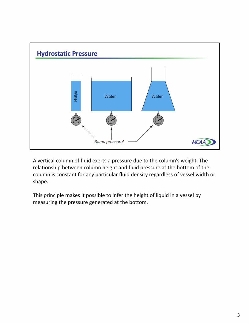
A vertical column of fluid exerts a pressure due to the column’s weight. The relationship between column height and fluid pressure at the bottom of the column is constant for any particular fluid density regardless of vessel width or shape.
This principle makes it possible to infer the height of liquid in a vessel by measuring the pressure generated at the bottom.
3

Any type of pressure-sensing instrument may be used as a liquid level transmitter by means of this principle. In this photograph, you see a pressure transmitter being used to measure the height of colored water inside a clear plastic tube.
The critically important factor in liquid level measurement using hydrostatic pressure is liquid density. One must accurately know the liquid’s density in order to have any hope of measuring that liquid’s level using hydrostatic pressure. Having an accurate assessment of liquid density also implies that density must remain relatively constant despite other changes in the process. If the liquid density is subject to random variation, the accuracy of any hydrostatic pressure-based level instrument will correspondingly vary.
It should be noted, though, that changes in liquid density will have absolutely no effect on hydrostatic measurement of liquid mass, so long as the vessel has a constant cross-sectional area throughout its entire height.
In all cases, it is important to account for the proper “zero”, that is the pressure measuring point that is at the same elevation as the “zero level” point on the vessel. In many cases compensation must be made to account for zero depending on the positioning of the instrument.
4

Differential pressure transmitters are the most common pressure-sensing device used in this capacity to infer liquid level within a vessel. In the hypothetical case of the oil vessel considered here, the transmitter would connect to the vessel in this manner, with the high side toward the process and the low side vented to atmosphere.
Connected as shown, the differential pressure transmitter functions as a gauge pressure transmitter, responding to hydrostatic pressure exceeding ambient or atmospheric pressure. As liquid level increases, the hydrostatic pressure applied to the “high” side of the differential pressure transmitter also increases, driving the transmitter’s output signal higher. Any changes in atmospheric pressure, pushing down on the oil, are exactly offset by the atmospheric pressure entering the low or vented side of the transmitter.
5

Some pressure-sensing instruments are built specifically for hydrostatic measurement of liquid level in vessels, doing away with impulse tubing altogether in favor of a special kind of sealing diaphragm extending slightly into the vessel through a flanged pipe entry, commonly called a nozzle. A hydrostatic level transmitter with an extended diaphragm is shown here.
6

The calibration table for a transmitter close-coupled to the bottom of an oil storage tank would be as shown here, assuming a zero to twelve foot measurement range for oil height, an oil density of 40 pounds per cubic foot, and a 4-20 mA transmitter output signal range.
And finally, there also exist top-mount hydrostatic level gages for atmospherically vented tanks as shown here. Sensors are extended vertically downward to the bottom of the tank via cabling or tubing.
7

An interesting variation on this theme of direct hydrostatic pressure measurement, that you may well still run across in the field, is the use of a purge gas to measure hydrostatic pressure in a liquid-containing vessel. This eliminates the need for direct contact of the process liquid against the pressure-sensing element, which can be advantageous if the process liquid is corrosive. It can also enable placing the pressure sensing instrument in a controlled environment, with no electrical wiring running to the vessel.
Such systems are often called bubble tube or dip tube systems, the former name being appropriately descriptive for the way purge gas bubbles out the end of the tube as it is submerged in process liquid. A key detail of a bubble tube system is to provide a means of limiting gas flow through the tube, so the purge gas backpressure properly reflects hydrostatic pressure at the end of the tube with no additional pressure due to frictional losses of purge flow through the length of the tube. Most bubble tube systems, therefore, are provided with some means of monitoring purge gas flow, typically with a rotameter Mechanical flowmeter or with a sight feed bubbler.
If the purge gas flow is not too great, gas pressure measured anywhere in the tube system downstream of the needle valve will be equal to the hydrostatic pressure of the process liquid at the bottom of the tube where the gas escapes. In other words, the purge gas acts to transmit the liquid’s hydrostatic pressure to some remote point where a pressure-sensing instrument is located.
A general rule-of-thumb is to limit purge gas flow to the point where you can easily count individual bubbles exiting the bubble tube or inside the sight feed bubbler if one is provided on the system.
8

A very common scenario for liquid level measurement is where the pressure-sensing instrument is not located at the same level as the 0% measurement point. This shows an example of this, where a differential pressure transmitter is being used to sense hydrostatic pressure of colored water inside a clear vertical plastic tube.
9

Consider the example of a pressure sensor measuring the level of liquid ethanol in a storage tank. The measurement range for liquid height in this ethanol storage tank is 0 to 40 feet, but the transmitter is located 30 feet below the tank.
This means the transmitter’s impulse line contains a 30-foot elevation head of ethanol, so the transmitter “sees” 30 feet of ethanol when the tank is empty and 70 feet of ethanol when the tank is full. A 3-point calibration table for this instrument would look like this, assuming a 4 to 20 mA DC output signal range. Such calibration forces a 0% level output or 4 ma despite the fact that the transmitter sees feet of head.
The term for describing the condition where the lower range value or LRV of the transmitter’s calibration is a positive number, is called zero suppression. If the zero offset is reversed, therefore the transmitter mounted at a location higher than the 0% process level, it is referred to as zero elevation.
10

Another common scenario and example of zero suppression is where the transmitter is mounted at or near the vessel’s bottom, but the desired level measurement range does not extend to the vessel bottom.
In this example, the transmitter is mounted exactly at the same level as the vessel bottom, but the level measurement range goes from 4 feet to 9 feet, a 5 foot span. At the level of castor oil deemed 0%, the transmitter “sees” a hydrostatic pressure of 1.68 PSI and at the 100% castor oil level the transmitter “sees” a pressure of 3.78 PSI. Thus, these two pressure values would define the transmitter’s lower and upper range values.
11

If the transmitter is elevated above the process connection point, it will most likely “see” a negative pressure or vacuum with an empty vessel owing to the pull of liquid in the line leading down from the instrument to the vessel. It is vitally important in elevated transmitter installations to use a remote seal rather than an open Impulse line, so liquid cannot dribble out of this line and into the vessel.
In this example, we see a remote seal system with a fill fluid having a density of 58.3 lb/ft3, and a process level measurement range of 0 to 11 feet of sea water, the density = 64 lb/ft. The transmitter elevation is 6 feet, which means it will “see” a vacuum of -2.43 PSI when the vessel is completely empty. This, of course, will be the transmitter’s calibrated lower range value. The upper range value will be the pressure “seen” with 11 feet of sea water in the vessel. This much sea water will contribute an additional 4.89 PSI of hydrostatic pressure at the level of the remote seal diaphragm, causing the transmitter to experience a pressure of +2.46 PSI
12

The simple and direct relationship between liquid height in a vessel and pressure at the bottom of that vessel is ruined if another source of pressure exists inside the vessel other than hydrostatic or elevation head. This is virtually guaranteed to be the case if the vessel in question is unvented. Any gas or vapor pressure accumulation in an enclosed vessel will add to the hydrostatic pressure at the bottom, causing any pressure-sensing instrument to falsely register a high level.
A pressure transmitter has no way of “knowing” how much of the sensed pressure is due to liquid elevation and how much of it is due to pressure existing in the vapor space above the liquid. Unless a way can be found to compensate for any non-hydrostatic pressure in the vessel, this extra pressure will be interpreted by the transmitter as additional liquid level.
Moreover, this error will change as gas pressure inside the vessel changes, so it cannot simply be “calibrated away” by a static zero shift within the instrument. The only way to hydrostatically measure liquid level inside an enclosed or non-vented vessel is to continuously compensate for gas pressure.
13

Fortunately, the capabilities of a differential pressure transmitter make this a simple task. All we need to do is connect a second impulse line, called a compensating leg, from the “Low” port of the transmitter to the top of the vessel, so the “Low” side of the transmitter experiences nothing but the gas pressure enclosed by the vessel, while the “High” side experiences the sum of gas and hydrostatic pressures. Since a differential pressure transmitter responds only to differences in pressure between “High” and “Low” sides, it will naturally subtract the gas pressure to yield a measurement based solely on hydrostatic pressure.
The amount of gas pressure inside the vessel now becomes completely irrelevant to the transmitter’s indication, because its effect is canceled at the differential pressure instrument’s sensing element. If gas pressure inside the vessel were to increase while liquid level remained constant, the pressure sensed at both ports of the differential pressure transmitter would increase by the exact same amount, with the pressure difference between the “high” and “low” ports remaining absolutely constant with the constant liquid level. This means the instrument’s output signal is a representation of hydrostatic pressure only, which represents liquid height, assuming a known liquid density.
14

Unfortunately, it is common for enclosed vessels to hold condensable vapors, which may over time fill a compensating leg full of liquid. If the tube connecting the “Low” side of a differential pressure transmitter fills completely with a liquid, this will add a hydrostatic pressure to that side of the transmitter, causing another calibration shift. This wet leg condition makes level measurement more complicated than a dry leg condition where the only pressure sensed by the transmitter’s “Low” side is gas pressure.
Gas pressure still cancels due to the differential nature of the pressure transmitter, but now the transmitter’s output indicates a difference of hydrostatic pressures between the vessel and the wet leg, rather than just the hydrostatic pressure of the vessel’s liquid level. Fortunately, the hydrostatic pressure generated by the wet leg will be constant, so long as the density of the condensed vapors filling that leg is constant. If the wet leg’s hydrostatic pressure is constant, we can compensate for it by calibrating the transmitter with an intentional zero shift, so it indicates as though it were measuring hydrostatic pressure on a vented vessel.
15

We may ensure a constant density of wet leg liquid by intentionally filling that leg with a liquid known to be denser than the densest condensed vapor inside the vessel. We could also use a differential pressure transmitter with remote seals and capillary tubes filled with liquid of known Density.
16

An alternative to using a compensating leg to subtract gas pressure inside an enclosed vessel is to simply use a second pressure transmitter and electronically subtract the two pressures in a computing device.
This approach enjoys the distinct advantage of avoiding a potentially wet compensating leg, but suffers the disadvantages of extra cost and greater error due to the potential calibration drift of two transmitters rather than just one. Such a system is also impractical in applications where the gas pressure is substantial compared to the hydrostatic or elevation head pressure.
17

If we add a third pressure transmitter to the electronic differential pressure system, located a known distance (x) above the bottom transmitter, we have all the pieces necessary for what is called a tank expert system. These systems are used on large storage tanks operating at or near atmospheric pressure, and have the ability to measure infer liquid height, liquid density, total liquid volume, and total liquid mass stored in the tank.
The pressure difference between the bottom and middle transmitters will change only if the liquid density changes8, since the two transmitters are separated by a known and fixed height difference.
The accurate measurement of liquids in storage tanks is not just useful for process operations, but also for conducting business affairs. Whether the liquid represents raw material purchased from a supplier, or a processed product ready to be pumped out to a customer, both parties have a vested interest in knowing the exact quantity of liquid bought or sold. Measurement applications such as this are known as custody transfer, because they represent the transfer of custody or ownership of a substance exchanged in a business agreement. In some instances, both buyer and seller operate and maintain their own custody transfer instrumentation, while in other instances there is but one instrument, the calibration of which validated by a neutral party.
18

Hydrostatic pressure sensors may be used to detect the level of a liquid-liquid interface, if, and only if, the total height of liquid sensed by the instrument is fixed. A single hydrostatic-based level instrument cannot discern between a changing interface level and a changing total level, so the latter must be fixed in order to measure the former.
One way of fixing total liquid height is to equip the vessel with an overflow pipe, and ensure that drain flow is always less than incoming flow, forcing some flow to always go through the overflow pipe. This strategy naturally lends itself to separation processes, where a mixture of light and heavy liquids are separated by their differing densities.
Here we see a practical application for liquid-liquid interface level measurement. If the goal is to separate two liquids of differing densities from one another, we need only the light liquid to exit out the overflow pipe and only the heavy liquid to exit out the drain pipe. This means we must control the interface level to stay between those two piping points on the vessel. If the interface drifts too far up, heavy liquid will be carried out the overflow pipe; and if we let the interface drift too far down, light liquid will flow out of the drain pipe. The first step in controlling any process variable is to measure that variable, and so here we are faced with the necessity of measuring the interface point between the light and heavy liquids.
19

Displacer level instruments exploit Archimedes’ Principle to detect liquid level by continuously measuring the weight of a rod immersed in the process liquid. As liquid level increases, the displacer rod experiences a greater buoyant force, making it appear lighter to the sensing instrument, which interprets the loss of weight as an increase in level and transmits a proportional output signal.
20

This photograph shows a pneumatic transmitter measuring condensate level in a knockout drum for natural gas service. The instrument itself appears on the right-hand side of the photo, topped by a grey-colored “head” with two pneumatic pressure gauges visible. The displacer “cage” is the vertical pipe immediately behind and below the head unit. Note that a sightglass level gauge appears on the left-hand side of the knockout chamber or condensate boot for visual indication of condensate level inside the process vessel.
21
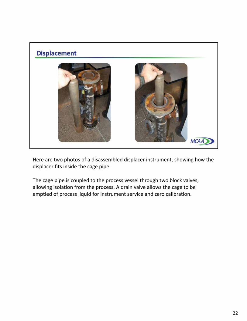
Here are two photos of a disassembled displacer instrument, showing how the displacer fits inside the cage pipe.
The cage pipe is coupled to the process vessel through two block valves, allowing isolation from the process. A drain valve allows the cage to be emptied of process liquid for instrument service and zero calibration.
22

Ultrasonic level instruments measure the distance from the transmitter, located at some high point, to the surface of a process material located further below. The time-of-flight for a sound pulse indicates this distance, and is interpreted by the transmitter electronics as process level. These transmitters may output a signal corresponding either to the fullness of the vessel called fillage or the amount of empty space remaining at the top of a vessel called ullage.
Ullage is the “natural” mode of measurement for this sort of level instrument, because the sound wave’s time-of-flight is a direct function of how much empty space exists between the liquid surface and the top of the vessel. Total tank height will always be the sum of fillage and ullage, though. If the ultrasonic level transmitter is programmed with the vessel’s total height, it may calculate fillage via simple subtraction.
23

The instrument itself consists of an electronics module containing all the power, computation, and signal processing circuits; plus an ultrasonic transducer to send and receive the sound waves. This transducer is typically piezoelectric in nature, being the equivalent of a very high-frequency audio speaker. Different sensing frequencies are used for different target materials, higher frequencies for detecting liquids and lower frequencies for solids. A typical example is shown in this photograph.
24

Ultrasonic level instruments enjoy the advantage of being able to measure the height of solid materials such as powders and grains stored in vessels, not just liquids. Certain challenges unique to these level measurement applications include low material density not causing strong reflections, and uneven profiles causing reflections to be scattered laterally instead of straight back to the ultrasonic instrument. A classic problem encountered when measuring the level of a powdered or granular material in a vessel is the angle of repose formed by the material as a result of being fed into the vessel at one point.
In the strictest sense, a vessel with such an angled material does not have a specific “level”. The user must decide what he really wants to determine: level to avoid overflow, inventory volume or level to avoid going empty. Only then can he determine at what point on the angled surface to seek a “level” measurement. Once making that determination, other challenges remain.
This angled surface is difficult for an ultrasonic device to detect if the frequency is not properly selected because it tends to scatter the sound waves laterally instead of reflecting them strongly back toward the instrument. However, even if the scattering problem is not significant, there still remains the problem of interpretation or what is the instrument actually measuring? The detected level near the vessel wall will certainly register less than at the center, but the level detected mid-way between the vessel wall and vessel center may not be an accurate average of those two heights. Moreover, this angle may decrease over time if mechanical vibrations cause the material to “flow” and tumble from center to edge.
25

In fact, the angle will probably reverse itself if the vessel empties from a center-located chute. For this reason, solids storage measurement applications demanding high accuracy generally use other techniques, such as weight-based measurement. Ultrasonics are challenged by the effects of airborne dusts as the sound waves are attenuated and the reflection from the actual material surface can be lost. This is most problematic at low levels when the transit path is longest.
Since the speed of sound is so important to accurate distance calculations for ultrasonic instruments, some ultrasonic level instruments are equipped with temperature sensors to measure the temperature of the fluid through which the sound waves travel. A formula programmed into the transmitter calculates the speed of sound based on temperature, so the instrument may continuously compensate for changes in sound velocity rooted in temperature changes, and therefore maintain superior accuracy over a wide range of ambient conditions. In the vast majority of ultrasonic level transmitter installations, where the instrument is mounted above the liquid level such that the sound waves travel through air, bounce off liquid, and travel back through air, it is the speed of sound through air that matters. The speed of sound through liquid is irrelevant in these applications, since most of the acoustic energy reflects off the liquid surface and therefore never travels through it. However, the speed of sound through accumulated vapors arising from the stored liquid must be considered.
In all ultrasonic applications the nuisance reflections from the tank structures that might be interpreted as a reflection from the material surface must be considered. Most modern systems permit the mapping and ignoring of nuisance reflections.
26
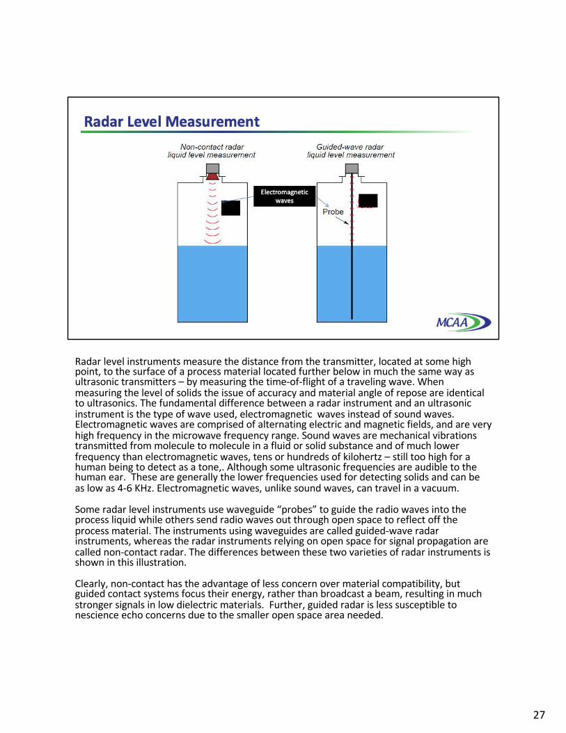
Radar level instruments measure the distance from the transmitter, located at some high point, to the surface of a process material located further below in much the same way as ultrasonic transmitters – by measuring the time-of-flight of a traveling wave. When measuring the level of solids the issue of accuracy and material angle of repose are identical to ultrasonics. The fundamental difference between a radar instrument and an ultrasonic instrument is the type of wave used, electromagnetic waves instead of sound waves. Electromagnetic waves are comprised of alternating electric and magnetic fields, and are very high frequency in the microwave frequency range. Sound waves are mechanical vibrations transmitted from molecule to molecule in a fluid or solid substance and of much lower frequency than electromagnetic waves, tens or hundreds of kilohertz – still too high for a human being to detect as a tone,. Although some ultrasonic frequencies are audible to the human ear. These are generally the lower frequencies used for detecting solids and can be as low as 4-6 KHz. Electromagnetic waves, unlike sound waves, can travel in a vacuum.
Some radar level instruments use waveguide “probes” to guide the radio waves into the process liquid while others send radio waves out through open space to reflect off the process material. The instruments using waveguides are called guided-wave radar instruments, whereas the radar instruments relying on open space for signal propagation are called non-contact radar. The differences between these two varieties of radar instruments is shown in this illustration.
Clearly, non-contact has the advantage of less concern over material compatibility, but guided contact systems focus their energy, rather than broadcast a beam, resulting in much stronger signals in low dielectric materials. Further, guided radar is less susceptible to nescience echo concerns due to the smaller open space area needed.
27

Non-contact radar transmitters are always mounted on the top side of a storage vessel. Modern radar transmitters are quite compact, as this photograph shows.
Reliable detection of solids in a dusty environment is more easily done with guided wave radar than either non-contact radar or ultrasonics due to limited signal scatter. Probes used in guided-wave radar instruments may be single metal rods or cables, parallel pairs of metal rods, or a coaxial metal rod-and-tube structure. Single-rod probes radiate the most energy, whereas coaxial probes do the best job guiding the microwave energy to the liquid interface and back.
However, single-rod probes are much more tolerant of process fouling than two-rod or especially coaxial probes, where sticky masses of viscous liquid and/or solid matter cling to the probe. Such fouling deposits, if severe enough, will cause radio energy reflections that “look” to the transmitter like the reflection from an actual liquid level or interface. Fouling is more problematic on two conductor wave guides, either coaxial or parallel, than it is on single conductor for two reasons. First mechanically they are less prone to adhering material. Secondly their surface wave propagation mode can travel over and around certain levels of buildup; whereas nearly all of the wave propagation energy in the two conductor scenario must travel through the built up material.
28

Non-contact radar instruments rely on an antenna to direct microwave energy into the vessel, and to receive the echo or return energy. These antennae must be kept clean and dry, which may be a problem if the liquid being measured emits condensable vapors. For this reason, non-contact radar instruments are often separated from the vessel interior by means of a dielectric window, made of some substance that is relatively “transparent” to radio waves yet acts as an effective vapor barrier.
If the radar instrument uses a digital network protocol to communicate information with a host system, such as HART or any number of “fieldbus” standards, it thusly can output more than one piece of information, performing as a multi-variable transmitter, transmitting both the interface level measurement and the total liquid level measurement simultaneously. This capability is rather unique to guided-wave radar transmitters, and is very useful in some processes because it eliminates the need for multiple instruments measuring multiple levels. In fact guided-wave is the only technology that can track two material levels when both are changing.
29

Another form of echo-based level measurement is laser, which uses pulses of laser light reflected off the surface of a liquid to detect the liquid level. Perhaps the most limiting factor with laser measurement is the necessity of having a sufficiently reflective surface for the laser light to “echo” off of. Many liquids are not reflective enough for this to be a practical measurement technique, and the presence of dust or thick vapors in the space between the laser and the liquid will disperse the light, weakening the light signal and making the level more difficult to detect. However, many liquid applications where the target material is opaque laser performance is successful. Laser systems are not suitable for liquid surfaces that are turbulent since the laser, by definition, is narrow and uni-directional and can easily reflect away at another angle. Laser technology is particularly advantages when needing a narrowly focused measuring signal to avoid surrounding obstacles which cannot be achieved by other non-contact radar or ultrasonic technologies. Laser technology has been successfully applied to many solid material applications and is capable of tolerating a reasonable amount of dust.
However, lasers have been applied with great success in measuring distances between objects. Applications of this technology include motion control on large machines, where a laser points at a moving reflector, the laser’s electronics calculating distance to the reflector based on the amount of time it takes for the laser “echo” to return. The advent of mass-produced, precision electronics has made this technology practical and affordable for many applications.
30

Weight-based level instruments sense process level in a vessel by directly measuring the weight of the vessel. If the vessel’s empty weight or tare weight is known, process weight becomes a simple calculation of total weight minus tare weight. Obviously, weight-based level sensors can measure both liquid and solid materials, and they have the benefit of providing inherently linear mass storage measurement. Load cells or strain gauges bonded to a steel element of precisely known modulus are typically the primary sensing element of choice for detecting vessel weight. As the vessel’s weight changes, the load cells compress or relax on a microscopic scale, causing the strain gauges inside to change resistance. These small changes in electrical resistance become a direct indication of vessel weight.
This photograph shows three bins, each one supported by pillars equipped with load cells near their bases.
31
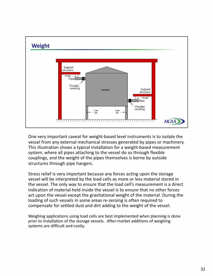
One very important caveat for weight-based level instruments is to isolate the vessel from any external mechanical stresses generated by pipes or machinery. This illustration shows a typical installation for a weight-based measurement system, where all pipes attaching to the vessel do so through flexible couplings, and the weight of the pipes themselves is borne by outside structures through pipe hangers.
Stress relief is very important because any forces acting upon the storage vessel will be interpreted by the load cells as more or less material stored in the vessel. The only way to ensure that the load cell’s measurement is a direct indication of material held inside the vessel is to ensure that no other forces act upon the vessel except the gravitational weight of the material. During the loading of such vessels in some areas re-zeroing is often required to compensate for settled dust and dirt adding to the weight of the vessel.
Weighing applications using load cells are best implemented when planning is done prior to installation of the storage vessels. After-market additions of weighing systems are difficult and costly.
32

Another approach to level measurement is the Servo gauge. A displacer is suspended from a very strong and flexible measuring wire stored on a measuring drum. The density of the displacer is higher than the density of the liquid. The displacer on level is partly immersed in the liquid.
The basic idea is that the displacer in a liquid produces an upward force equal to the weight of the displaced product. The apparent weight is the weight of the displacer minus the weight of the displaced product.
The hart of the servo gauge is an advanced and very accurate force transducer that continuously measures the apparent weight of the displacer. A weight corresponding with the apparent weight of the displacer on level is programmed by software settings.
In equilibrium condition, the weight of the partly immersed displacer balances against the weight programmed to be measured by the force transducer.
When emptying the tank, the liquid level starts moving downwards. The force transducer will experience an increasing weight, as upward force is no longer acting on the displacer.
Smart communication between the force transducer and the servo controller will ensure that the displacer is lowered. The servo motor drives the measuring drum to unwind measuring wire until the displacer is partly immersed in liquid again until the measured or apparent weight equals the programmed weight.
The process is reversed when filling the tank.
33
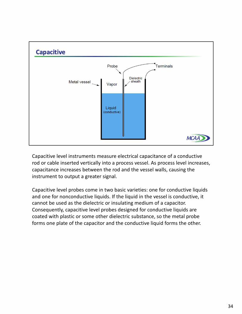
Capacitive level instruments measure electrical capacitance of a conductive rod or cable inserted vertically into a process vessel. As process level increases, capacitance increases between the rod and the vessel walls, causing the instrument to output a greater signal.
Capacitive level probes come in two basic varieties: one for conductive liquids and one for nonconductive liquids. If the liquid in the vessel is conductive, it cannot be used as the dielectric or insulating medium of a capacitor. Consequently, capacitive level probes designed for conductive liquids are coated with plastic or some other dielectric substance, so the metal probe forms one plate of the capacitor and the conductive liquid forms the other.
34

If the liquid is non-conductive, it may be used as the dielectric itself, with the metal wall of the storage vessel forming the second capacitor plate.
Capacitive level instruments may be used to measure the level of solids like powders and granules in addition to liquids. In these applications, any solid substance is almost always non-conductive, and therefore the permittivity of the substance becomes a factor in measurement accuracy. This can be problematic, as moisture content variations in the solid may greatly affect permittivity, as can variations in granule size. They are not known for great accuracy, though, primarily due to sensitivity to changes in process permittivity.
For very low dielectrics, signal strength or change in capacitance can be increased by bringing a grounded surface closer to the probe. That may arise from installing closer to the vessel wall, or from adding a ground tube or stilling well to create a coaxial probe.
35
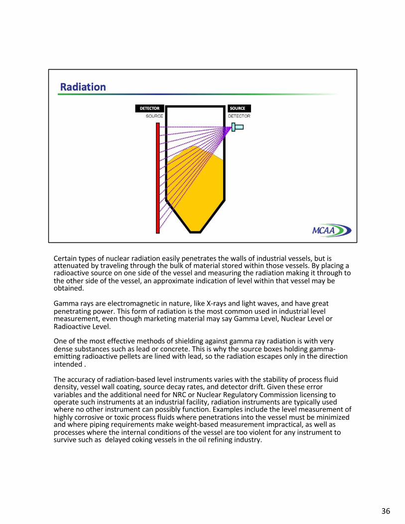
Certain types of nuclear radiation easily penetrates the walls of industrial vessels, but is attenuated by traveling through the bulk of material stored within those vessels. By placing a radioactive source on one side of the vessel and measuring the radiation making it through to the other side of the vessel, an approximate indication of level within that vessel may be obtained.
Gamma rays are electromagnetic in nature, like X-rays and light waves, and have great penetrating power. This form of radiation is the most common used in industrial level measurement, even though marketing material may say Gamma Level, Nuclear Level or Radioactive Level.
One of the most effective methods of shielding against gamma ray radiation is with very dense substances such as lead or concrete. This is why the source boxes holding gamma-emitting radioactive pellets are lined with lead, so the radiation escapes only in the direction intended .
The accuracy of radiation-based level instruments varies with the stability of process fluid density, vessel wall coating, source decay rates, and detector drift. Given these error variables and the additional need for NRC or Nuclear Regulatory Commission licensing to operate such instruments at an industrial facility, radiation instruments are typically used where no other instrument can possibly function. Examples include the level measurement of highly corrosive or toxic process fluids where penetrations into the vessel must be minimized and where piping requirements make weight-based measurement impractical, as well as processes where the internal conditions of the vessel are too violent for any instrument to survive such as delayed coking vessels in the oil refining industry.
36

Let’s take a look at some of the most basic Level measurement schemes that you will still find in the field on occasion, the sightglass and the float.
The level gauge, or sightglass is to liquid level measurement as manometers are to pressure measurement, a very simple and effective technology for direct visual indication of process level. In its simplest form, a level gauge is nothing more than a clear tube through which process liquid may be seen. This photograph shows a simple example of a sightglass.
37

A functional diagram of a sightglass shows how it visually represents the level of liquid inside a vessel such as a storage tank.
A level gauge is not unlike a U-tube manometer, with equal pressures applied to both liquid columns, one column being the liquid in the gauge sightglass, the other column being the liquid in the vessel.
Level gauge valves exist to allow replacement of the glass tube without emptying or depressurizing the process vessel. These valves are usually equipped with flow-limiting devices in the event of a tube rupture, so too much process fluid does not escape even when the valves are fully open.
Some level gauges called reflex gauges are equipped with special optics to facilitate the viewing of clear liquids, which is problematic for simple glass-tube sightglasses.
38
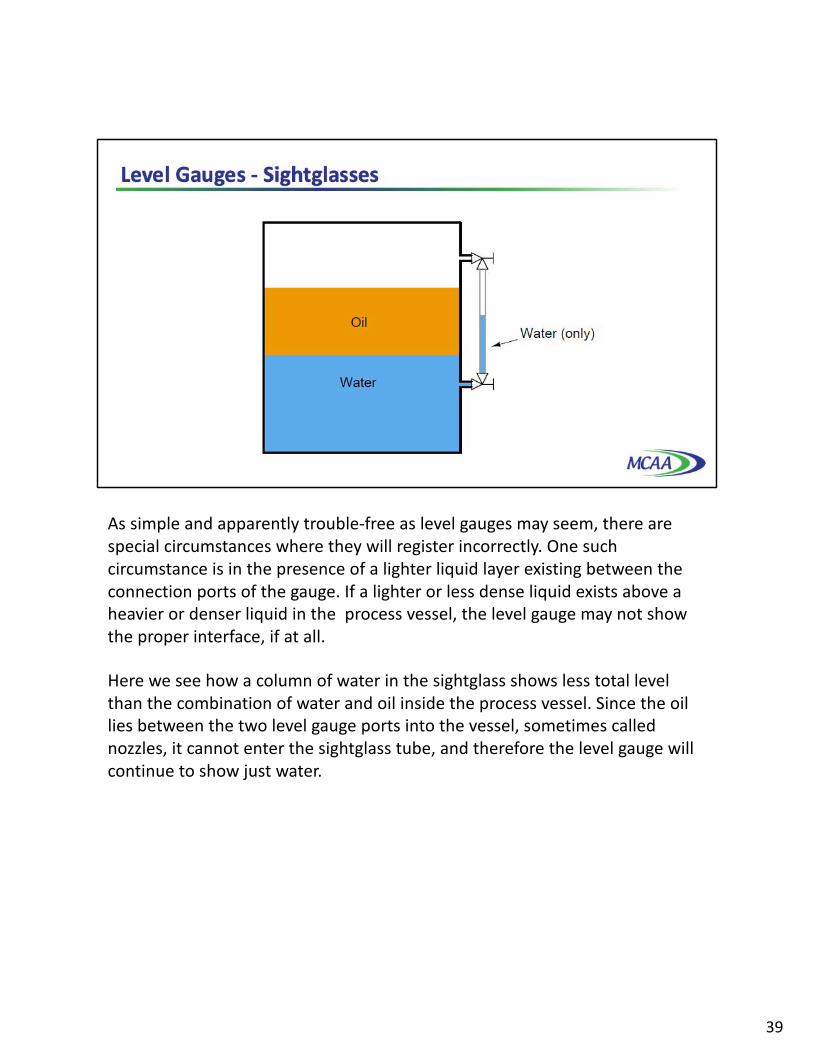
As simple and apparently trouble-free as level gauges may seem, there are special circumstances where they will register incorrectly. One such circumstance is in the presence of a lighter liquid layer existing between the connection ports of the gauge. If a lighter or less dense liquid exists above a heavier or denser liquid in the process vessel, the level gauge may not show the proper interface, if at all.
Here we see how a column of water in the sightglass shows less total level than the combination of water and oil inside the process vessel. Since the oil lies between the two level gauge ports into the vessel, sometimes called nozzles, it cannot enter the sightglass tube, and therefore the level gauge will continue to show just water.
39

Perhaps the simplest form of solid or liquid level measurement is with a float or a device that rides on the surface of the fluid or solid within the storage vessel. The float itself must be of substantially lesser density than the substance of interest, and it must not corrode or otherwise react with the substance.
The photograph on the right shows the “measurement head” of a spring-reel tape-and-float liquid level transmitter, with the vertical pipe housing the tape on its way to the top of the storage tank where it will turn 180 degrees via two pulleys and attach to the float inside the tank.
The spring reel’s angular position may be measured by a multi-turn potentiometer or a rotary encoder, located inside the “head” unit, then converted to an electronic signal for transmission to a remote display, control, and/or recording system. Such systems are used extensively for measurement of water and fuel in storage tanks.
40

"Plumb bob on cable" systems are particularly advantageous in applications with very long range, heavy dust, and with internal structural obstacles. A weight is suspended by a cable from a drum operated by a motor, and the motor unwinds the cable until the weight reaches the material surface. The length of the unwound cable is the measured distance to the material, calculated using electrical pulses from an encoder assembly.
The advantages of this technology is that it is reasonably accurate and is suitable for very low bulk density materials. Its disadvantages include mechanical wearing on the parts, resulting in maintenance costs and possible damage to the weight and/or cable under extreme load. It also cannot usually be used during filling because the weight can become stuck under falling material.
41

Disturbances in the liquid tend to complicate liquid level measurement. These disturbances may result from liquid introduced into a vessel above the liquid level splashing into the liquid’s surface, the rotation of agitator paddles, and/or turbulent flows from mixing pumps. Any source of turbulence for the liquid surface or liquid-liquid interface is especially problematic for echo-type level sensors, which only sense interfaces between vapors and liquids, or liquids and liquids.
If it is not possible to eliminate disturbances inside the process vessel, a relatively simple accessory one may add to the process vessel is a vertical length of pipe called a stilling well. To understand the principle of a stilling well, first consider the application of a hydraulic oil reservoir where we wish to continuously measure oil level. The oil flow in and out of this reservoir will cause problems for the displacer element.
42

A section of vertical pipe installed in the reservoir around the displacer will serve as a shield to all the turbulence in the rest of the reservoir. The displacer element will no longer be subject to a horizontal blast of oil entering the reservoir, nor any wave action to make it bob up and down. This section of pipe quiets, or stills, the oil surrounding the displacer, making it easier to measure oil level.
43

Stilling wells may be used in conjunction with many types of level instruments: floats, displacers, ultrasonic, radar, and laser to name a few. If the process application necessitates liquid-liquid interface measurement, however, the stilling well must be properly installed to ensure the interface level inside the well match the interface levels in the rest of the vessel. Consider this example of using a stilling well in conjunction with a tape-and-float system for interface measurement.
In the left-hand installation where the stilling well is completely submerged, the interface levels will always match. In the right-hand installation where the top of the stilling well extends above the total liquid level, however, the two levels may not always match.
44

This potential problem for the non-submerged stilling well is graphically illustrated here. The problem here is analogous to what we see with sightglass-style level gauges; interfaces may be reliably indicated if and only if both ends of the sightglass are submerged.
45

If it is not possible or practical to ensure complete submersion of the stilling well, an alternative technique is to drill holes or cut slots in the well to allow interface levels to equalize inside and outside of the well tube.
Such equalization ports are commonly found as a standard design feature on coaxial probes for guided-wave radar level transmitters, where the outer tube of the coaxial transmission line acts as a sort of stilling well for the fluid. Coaxial probes are typically chosen for liquid-liquid interface radar measurement applications because they do the best job of preventing dispersion of the radio energy, but the “stilling well” property of a coaxial probe practically necessitates these equalization ports to ensure the interface level within the probe always matches the interface level in the rest of the vessel.
46

47

48

49

50