welcome to the dac â€08 verification horizons!
TRANSCRIPT

If last year’s DAC issue was “super-sized,” then I am pleased to welcome you to this year’s super-duper-sized DAC issue of Verification Horizons.
As I write this note, I’ve just gotten home from coaching my son’s baseball team this evening. It was a great game, and there are a number of things I could write about it. But given that we achieved our first win of the season (after three losses), I find myself thinking about “the thrill of victory.” My coaching philosophy is simply for the boys to do their best and have fun. My secondary philosophy is that it’s always more fun when you win, so I always encourage the boys to work together, stay focused on the game, and think about what they need to do on every play.
In gathering my thoughts to write to you tonight, I couldn’t help but reflect back a few months to Dr. Wally Rhines’ keynote address at DVCon, entitled “Ending Endless Verification.” The keynote has served as a “game plan” for us in Design Verification Technology here at Mentor, and it should come as no surprise that this issue of Verification Horizons highlights each of the featured technologies discussed by Dr. Rhines, including several articles that highlight the Open Verification Methodology (OVM).
Our feature article, “Achieving DO-254 Design Assurance Using Advanced Verification Methods,” tells how Mentor and our friends at XtremeEDA teamed up to help Rockwell Collins transition their verification processes from “traditional” directed testing to today’s constrained-random, coverage-driven verification provided by Questa® and the Advanced Verification Methodology (AVM). The article illustrates the productivity advantages of using the AVM to develop the environment, with DO-254 compliance achieved through the superior ability of Questa
Welcome to the DAC ‘08Verification Horizons!By Tom Fitzpatrick, Editor and Verification Technologist
Partners’ Corner (pages 29-48)
Design Verification
Using Questa and the OVM,
A Practical Guide to OVM–Part 1
Dynamic Construction and
Configuration of Testbenches,
and OVM Productivity
using EZVerify
Achieving DO-254 Design Assurance using Advanced Verification Methods...page 7 Transitioning verification processes from directed testing to constrained-random, coverage-driven verification. more
Ending Endless Verification with 0-In Formal...page 13 How to apply 0-In® formal tools to improve productivity. more
Intelligent Testbench Automation Turbo-Charges Simulation...page 16 How the new inFact™ iTBA tool can turbo charge your regression farm. more
Using Questa Multi-View Verifi-cation Components and OVM for AXI Verification...page 19: Single model support for complete verification at all levels: system, transaction, & RTL. more
What is a Standard?...page 23 Is the OVM a de facto standard..? more
Firmware Driven OVM Testbench...page 26 Seamless® OVM-compliant interfaces add firmware execution (and debug). more
Tribal Knowledge: Requirements-Centric Verification...page 49: Towards a structured way to gather and maintain design requirements. more
“If you’re going to be at DAC, ...stop by the
Mentor booth, and feelfree to ask for me if you’d like to say “hi.” We’d love
the opportunity to talk to you about how the Mentor team
can help you experience “the thrill of victory” on your next project.”
—Tom Fitzpatrick
A PUBLICATION OF MENTOR GRAPHICS JUNE 2008—VOLUME 4, ISSUE 2

2
Verification Management to track the coverage results of the random environment and, most importantly, correlate those results back to the original design requirements. While not every project requires DO-254 compliance, the ability to track multiple types of coverage and correlate them back to the requirements is a productivity gain that every project can realize. Everything in this article is directly applicable to the OVM as well.
The next three articles explain how we’re delivering on some of the issues raised in Dr. Rhines’ keynote. Harry Foster leads off with a discussion of how to apply our 0-In® formal tools to improve productivity. As you’ll see, the real advantage comes from achieving more verification per cycle, rather than just adding more cycles of verification. This productivity discussion is continued in our next article, which explains how our new inFact™ iTBA tool can turbo charge your regression farm by automatically distributing non-redundant, rule-based, targeted simulations across multiple CPUs — another way of getting more verification per cycle. The third article in this arc introduces our new Multi-View Verification Components (MVCs). An MVC is a single model that supports complete verification at the system, transaction, and register-transfer levels. The article explains how our AXI MVC can be used as part of a constrained-random OVM environment to verify an AMBA AXI system. Taken together, the combination of formal methods, intelligent testbench automation, and multi-abstraction models provide the keys to ending endless verification. The OVM and Questa provide the foundation to allow them to work together.
The next set of articles provides some wonderful insights into the extraordinary growth of the OVM since its initial release back in January. As a member of the OVM development team from its inception, I must confess to a certain level of pride at how well the OVM has been received — a feeling not unlike being the coach of a winning baseball team.
With the recent formation of the Accellera Verification Intellectual Property Technical Subcommittee (VIP-TSC), there has been quite a bit of talk about the industry finally getting to the point of standardizing on a verification methodology. As Mentor’s representative to the VIP-TSC, I’d like to take this opportunity to point out that the TSC is currently chartered only to define interoperability between methodologies; it is not to develop a new methodology (nor is its purpose to pick an existing one on which to standardize). Since the
OVM is open-source, the TSC has full access to all of the OVM, and we look forward to working with the TSC to solve the interoper-ability problem for the industry. Our first OVM article addresses the question of a standard methodology by making the case that the OVM, because it is open-source, is ideally suited, and well on its way, to becoming a de facto standard. The success of the OVM just reinforces that feeling of “the thrill of victory.”
The next few articles reinforce this point by showing how much the OVM ecosystem is growing, both within Mentor and throughout the industry. We begin with a discussion of how Mentor’s Seamless® HW/SW co-simulation tool has added OVM-compliant interfaces to add firmware execution (and debug) as one of the stimulus generation options for an OVM-based verification environment. To further illustrate the growth of the OVM ecosystem, we next have an expanded “Partners’ Corner” to highlight the activities of some of our Questa Vanguard Partners.
We begin with an engineer’s point-of-view on using the OVM with Questa. Our friends at PSI Electronics were quickly able to adopt the OVM to replace and improve on their previous methodology. Our next two articles are by two of our valued training partners. Doulos begins a series of articles that will span the next several issues of Verification Horizons to provide a Practical Guide to the OVM. The first installment of the series is a survey of what’s in the OVM release and a look at some of the basic concepts. Be sure to check back in the next issue for more valuable insight. After that, Willamette HDL shows how the OVM’s dynamic construction and configuration mechanisms can be used to foster reuse of verification components in different contexts. Then our friends at VeriEZ explain the static analysis capabilities of their EZVerify tool, which can automatically examine your OVM code to make sure it follows the proper guidelines.
Last, but not least, we close this issue with our Consultant’s Corner “Tribal Knowledge” article. Many of you may be familiar with Peet James from his years at Qualis, during which he published a number of papers and articles on verification. We’re pleased to welcome him to the Mentor family and the growing list of Verification Horizons contributors with his article on Requirements-Centric Verification.

3
So, getting back to baseball for a moment, I’m now faced with the challenge of helping the boys continue their winning ways. Granted, this is a much better challenge to have than to convince a losing team of 8–10 year-olds that they’ll win eventually, but it’s still a challenge. I’m hoping that the sweet taste of victory will motivate them to work even harder, but the emphasis will always be on doing their best and having fun.
If you’re going to be at DAC, I’d gently suggest the same advice. Stop by the Mentor booth, and feel free to ask for me if you’d like to say “hi.” We’d love the opportunity to talk to you about how the Mentor team can help you experience “the thrill of victory” on your next project.
Respectfully submitted,
Tom Fitzpatrick
Verification Technologist
Verification Horizons is a publication of Mentor Graphics Corporation, all rights reserved.
Editor: Tom Fitzpatrick
Program Manager: Rebecca Granquist
Senior Writer:Todd Burkholder
Wilsonville Worldwide Headquarters
8005 SW Boeckman Rd.
Wilsonville, OR 97070-7777
Phone: 503-685-7000
To subscribe visit: http://www.mentor.com/products/fv/verification_news.cfm

4
Page 7...Achieving DO-254 Design Assurance using Advanced Verification Methods by Dr. Paul Marriott, Director of Verification, XtremeEDA Corporation; David Landoll, Mentor Graphics; Dustin Johnson, Electrical Engineer, Rockwell Collins; Darron May, Product Manager, Mentor Graphics.
Page 13... Ending Endless Verification with 0-In Formalby Harry Foster, Chief Verification Scientist, Mentor Graphics
Page 16... Intelligent Testbench Automation Turbo-Charges Simulation by Mark Olen, Product Manager, Verification, Mentor Graphics
Page 19...Using Questa Multi-View Verification Components and OVM for AXI Verification by Ashish Kumar, Verification Division, Mentor Graphics
Page 23...What is a Standard? by Mark Glasser, Mentor Graphics Corporation & Mark Burton, GreenSoCs
Page 26...Firmware Driven OVM Testbench by Jim Kenney – SoC Verification Product Manager, Mentor Graphics
Table of Contents

5
Partners’ Corner:
Page 29...Design Verification Using Questa and the Open Verification Methodology: A PSI Engineer’s Point of View by Jean-Sébastien Leroy, Design Verification Engineer & Eric Louveau, Design Verification Manager, PSI Electronics
Page 35...A Practical Guide to OVM – Part 1by John Aynsley, CTO, Doulos
Page 40... Dynamic Construction and Configuration of Testbenchesby Mike Baird, Willamette HDL, Inc.
Page 44... OVM Productivity using EZVerifyby Sashi Obilisetty, VeriEZ
Page 49... Tribal Knowledge: Requirements-Centric Verificationby Peet James, Sr. Verification Consultant, Mentor Graphics

6
Mentor and our friends at XtremeEDA teamed up to help Rockwell Collins
transition their verification processes from “traditional”
directed testing to today’s constrained-random,
coverage-driven verification provided by Questa® and the Advanced Verification
Methodology (AVM).

7
DO-254 is a standard enforced by the FAA that requires certification of avionics suppliers’ designs and design processes to ensure reliability of airborne systems. Rockwell Collins had been using a traditional directed-testing approach to achieve DO-254 compliance [1]. This is time consuming and, as their designs were becoming more complex, they wanted to take advantage of the productivity gains a modern constrained-random coverage-driven environment provides, but still ensure the needs of the DO-254 process could be met.
A methodology built using SystemVerilog with Mentor’s Advanced Verification Methodology (AVM) [4] was assembled and a flow developed that linked the formal requirements documents through the verification management tools in Questa. This allowed coverage data to be used to satisfy the DO-254 process, and greatly reduced the verification effort required. The target design, an FPGA DMA engine, was recently certified using the flow developed to meet DO-254 Level A compliance, the highest level that is used in mission-critical systems.
The process flow developed for this project will be of interest to anyone who needs high levels of verification confidence with the productivity gains that methodologies such as the AVM or OVM provide.
INTRODUCTIONDO-254 is a process which, simply stated, ensures that all
specified design requirements have been verified in a repeatable and demonstrable way. The key aspect of this is that all the requirements of the system are well specified, and each of those requirements can be demonstrated to have been verified. Traditionally, a direct-testing approach is used as a test can be written for each requirement. Conceptually, a directed test essentially encapsulates one, or possibly several, functional coverage points [2]. Hence it is the linking of the functional coverage points to the design requirements which is really being used to verify those requirements.
XtremeEDA was contracted by Mentor Graphics to train the Rockwell Collins team in the use of the AVM, and design an environment and process whereby the linking of the functional coverage data to the formal requirements could be automated.
ORIGINAL METHODOLOGYHistorically, Rockwell Collins (RC) utilized a thorough DO- 254
compliant methodology of creating and running a large suite of self-checking directed tests, as well as performing manual and automatic analysis of the code (and any other methods as required by a particular program). However, although this methodology is thorough and produces a high quality design, some bugs may not be found until late in the design cycle, or during lab bring-up, which makes identifying, fixing, and re-verifying them more costly.
PROJECT OVERVIEWThis project, an FPGA DMA Engine, had increased complexity
due to high configurability, potentially exacerbating this situation. RC undertook the use of newer advanced verification methodologies in hope of achieving increased robustness, finding bugs earlier in the project cycle, and verifying the overall device more quickly. As a result, RC hoped to shorten the overall verification cycle and achieve better quality results.
Figure 1 shows the DMA Engine’s initial configuration set-up process, where the uP writes a list of DMA records to the Xfer Memory. These records describe repeatable transfers to be executed by the DMA
Achieving DO-254 Design Assurance using Advanced Verification Methods by Dr. Paul Marriott, Director of Verification, XtremeEDA Corporation; David Landoll, Mentor Graphics; Dustin Johnson, Electrical Engineer, Rockwell Collins; Darron May, Product Manager, Mentor Graphics

8
Engine once started. The exact set-up of these records is target device specific, thus the DMA Engine is highly configurable via these records. Once this set-up is complete, the DMA Engine is started and the data transfers begin (also shown in Figure 1, right-hand side). During regular data transfers, data moves between the Ethernet chip and the uP’s local RAM as well as between the local RAM and the uP.
There are several complexities with this design that increase the verification challenge. First, there are two types of data, namely Samples and Messages. The Messages queue up and must all be delivered. The Samples are from measurement devices that are infrequently updated compared to the speed of the uP. As such, it makes no sense to read from the sample ports faster than external measurements can change, as this would re-read the same data value over and over. As such, there are sampling clocks that indicate the correct time to sample these ports.
Many data transfers require a three-step process of first locking the port associated with the data transfer, then transferring the data and finally closing the port. Hence a single transfer can require numerous reads/writes. In addition, this behavior is highly configurable via the DMA records previously discussed. All these possible record types and combinations must be tested.
The combinations and permutations of these transfers and configurations makes the verification of this device challenging, and would require a large number of directed tests using the traditional methodology.
METHODOLOGY CRITERIAThe following criteria were used to select a better methodology:
1. It must pass the DO-254 compliance review2. It must use industry standard tools and languages3. It must interface with current and future designs4. It should support new hardware HVL constructs
that enable productivity gains
It was soon determined that SystemVerilog together with Mentor’s AVM could potentially satisfy all the above criteria if some effort was put into developing a process flow with DO-254 compliance as the foremost goal.
PRODUCTIVITY ENABLERSConstrained Random Generation
The term “random” can create confusion in the world of DO-254 compliance as 100% certainty is not usually associated with a random process. However, random in the context of verification means selecting values from a valid range, which is set by constraints. These constraints are determined by the design requirements, and the randomization within these constraints is to allow a more rapid exploration of the set of valid stimulus that is necessary to assure design compliance. The constraints can be visualized as a tree-like structure which, if every branch is explored, encapsulates all possible stimuli that can be applied to the design.
The branches are selected at random, but the specification of the branches themselves comes from the formal requirements. For a given seed, the process is entirely repeatable and this is an essential aspect of achieving compliance.
CoverageCompleteness is a necessary criterion for compliance. In directed-
testing, completeness is assured by running all tests. In a constrained-random environment, an automated means of measuring completeness is required. This is provided by coverage. Different kinds of coverage metrics can be collected and it is their aggregate which is used to determine completeness. This approach is referred to as the Total Coverage Model and is the process of aggregating the metrics from all tests and simulation runs into a composite dataset. A key point is that the design requirements can be mapped into coverage points which can be added by the verification engineers. With this linkage of coverage items to requirements in place, the coverage points provide clear confirmation that requirements have been met.

9
Design Intent SpecificationDesign Intent Specification refers to the ability to document the
expected design protocols in a tool readable format. For SystemVerilog, that format is called SystemVerilog Assertions (SVA). This feature of the SystemVerilog language allows the user to describe design signal activity over time so that it is constantly being checked during simulation [3]. These time-based signal behaviors are also known as temporal assertions.
While functional coverage captures and checks the design state at a moment in time, temporal assertions are used to check and cover design activity over time. Requirements often describe such design intent, or in other words, how the design should react to stimulus. Requirements of this type translate well into temporal assertions. Examples of these types of assertions include target protocol sequences, error recovery, or sampling of design state.
TRACEABILITYSimply put, DO-254 compliance means that the verification team
can demonstrate that they did, indeed, thoroughly verify all the design requirements and can repeat that effort if required to do so. The key to achieving this is traceability – i.e. demonstrating how each requirement was verified. Since coverage is being used to provide the feedback that the requirements have been verified, an automated process is essential to ensure productivity and repeatability and hence to provide an automated traceability path from each documented requirement to the coverage item or assertion that verified it.
The Verification Management environment (hereinafter referred to as VM) in Questa is a new feature that allows a “testplan” (or verification plan – the terms are interchangeable) to be linked to coverage data captured during simulation. In a DO-254 compliant methodology, a requirements capture tool is typically used to store the design specification and the testplan. The requirements management tool DOORS (from the company Telelogic) was used on this project. Links were created between the testplan maintained in DOORS, the VM testplan stored in the Unified Coverage Database (UCDB) and the results of actual simulation runs that were also stored in the UCDB. Merging the testplan and simulation run UCDBs provided feedback as to the current status of the overall compliance and verification effort. The flow is depicted in Figure 3.
There are essentially three steps to achieve requirements linking:
1. Exporting the testplan from DOORS
2. Linking the UCDB testplan to the coverage items
3. Merging the simulation results with the testplan
With this methodology there is not necessarily a one-to-one relationship between the requirements and testcases. There is however a strict auditable relationship between requirements and their assertions or coverage points. This provides the important traceability link that shows a requirement was covered (i.e. verified).
EXAMPLE PROCESSThe following are DOORS screen shots demonstrating the steps
required to meet supported requirements traceability. They illustrate the process of connecting requirements to tests, coverage items, and assertions.
The basic process is that requirements and test cases are entered in and managed within DOORs. DOORs can produce a testplan report that is the basis for the Questa testplan. The verification engineers fill in the testplan with the items that verify requirements have been covered. Verification is run and the coverage data is stored and then merged with the testplan. The final result is that the testplan contains coverage data that links to the requirements being tested.

10
Figure 4 (on the following page) shows the testplan entered into DOORS (note: for readability, the testcase description/detail text is omitted from these screenshots). It highlights a test case, the covergroup names that it is linked to, and the type of coverage the link refers to. In this figure, the in-links column shows the text from the object that is linked into that cell. In the case of 3.1.1.2.1, various objects that are defined elsewhere in the document are linked into that particular cell.
Figure 5 shows the hierarchical structure of the DOORS testplan following the Test Cases section. The orange and red triangles in the right column represent links – red for out links (in this case to the requirements document) and orange for in-links (in this case coming from the coverage objects).
Figure 6 (on the opposite page) shows the coverage object definitions (in this case, just the SystemVerilog covergroups are highlighted) and the right hand column shows that individual items in the covergroup definitions (such as coverpoints or cross-products) can be linked. The red triangles show these are out-links – which, in this case, are linked into the testcases shown in the previous diagram.
RESULTSPreliminary analysis shows that the project
team is happy with the decision to use these advanced verification methods [5]. They were able to adopt these new methods, as well as the SystemVerilog language with no real schedule penalties. The overall environment was up and running quickly. The verification team was ready to write tests before RTL design code was available, so the verification team wrote transaction level models for the device and used these for early testbench development and testing. Later, after the design was available, these transaction level models became the reference assuring design correctness.
Through this process, the project team found bugs that, in their words, “would have been tough to catch without randoms.” For example, a “FIFO full” problem was detected early in the project that required a complex scenario of reads and writes while the rest of the design was in a specific state.

11
In addition, the team reported that if they had attempted the traditional approach of directed tests, they would have faced writing and maintaining hundreds of individual tests. This would have become a difficult revision control management problem, as each test needs to be tracked back to individual requirements. In addition, this would have also become a challenging regression environment, with long run-times, difficult job spawning coordination and cumbersome coverage results merging.
The team also reported more thorough and efficient testing earlier in the project compared to their traditional methodology. In general, the same results are being checked in this methodology vs. their traditional directed test methodology. However, through the use of assertions, RC can now achieve much higher leverage from the creation of any given check. Previously, checks were written as part of a directed test, and were typically associated with the functionality of that directed test. Now, once a check is created, it can be continuously run across all simulations as part of the verification environment rather than being attached to specific directed tests.
Through the use of assertions, they “are checking hundreds of things each clock cycle” across all tests, verses a directed test that would perform these same checks only once typically at the end of a test. As such, the design is now more thoroughly checked all the time via assertions across all simulations.
While the team was creating the requirements-based assertions and coverage points, they found that some requirements had to be clarified in order to write assertions. The team found it helped to write requirements up-front such that they map well to assertions.
In general, the team recommended that the requirements be reviewed with a mapping to assertions in mind during the DO-254 Requirement Review process/cycle.
Initially the team struggled with “what to randomize” for constrained random testing. They found a balance between complete-randomization versus highly-constrained by splitting the verification into six different random tests. Each test randomizes a different aspect of the design behavior. This more easily allowed the team to understand the task
at hand and create a workable and efficient environment. To visualize this, refer to Figure 2 and imagine the tree structure being broken down into 6 different trees, each characterizing a different part of the required behavior. This makes the creation of the tree structure easier to comprehend and maintain. This does have the caveat of limiting some testing across the tests, as not all randomizations can take place simultaneously. However, the impact of this tradeoff can be mitigated by intelligently partitioning these tests such that important input concurrencies are contained within the same test.
The team also initially struggled to understand if the new testbench was operating as desired. They solved this issue by leveraging the embedded functional coverage points. Analyzing coverage results post-simulation provided the needed visibility.
As expected, the team did need to write some directed tests for conditions which are resistant to random stimulus.
CONCLUSIONThe methodology described here allows an advanced verification
methodology consisting of Constrained Random, Design Intent Specification, and the Total Coverage Model (unified coverage database) to satisfy the DO-254 process requirements: namely repeatability and demonstration of requirement satisfaction.
The use of DOORS as a tool to represent the requirements and test plan documents, and linking this into the features of Questa means that requirements traceability can be automated. Integrating the testplan

12
into the Questa Verification Management tool closes the feedback loop, allows the tracking of functional coverage results to the requirements listed in the testplan, and indicates when full coverage is achieved.
The ultimate verification goal of a DO-254 based approach is to demonstrate that the requirements have been satisfied with the highest possible confidence. The approach described here enables this goal on larger, more complex designs with increased robustness, earlier identification of bugs, and an overall improvement in efficiency and effectiveness.––
XtremeEDA Corporation (http://www.xtreme-eda.com), the leading ASIC and FPGA professional services company, has the key know-how required to address the challenges of applying leading edge verification methodologies to help customers deliver their projects in accordance with the functional and performance attributes specified, to the highest standards possible.
Rockwell Collins (NYSE: COL) is a pioneer in the development and deployment of innovative communication and aviation electronic solutions for both commercial and government applications.
REFERENCES:
[1] Henry Angulo, Asad Khan and Scott Morrison, “Rigorous Automated Verification Yields High Quality Silicon”, EDA DesignLine, April 24, 2007, paragraph 4http://www.edadesignline.com/199200993
[2] P. Marriott, S. Bailey, “Functional Coverage Using SystemVerilog”, in Proc. Of DVCon 2006, San Jose, CA, USA, February 2006
[3] Tom Fitzpatrick, “SystemVerilog Assertions Unify Design and Verification”, EETimes October 17, 2003. http://www.eetimes.com/news/design/showArticle.jhtml?articleID=16502229
[4] Mark Glasser, ed., Advanced Verification MethodologyCookbook, Rev. 3.0, Mentor Graphics 2007http://www.mentor.com/products/fv/_3b715c/cb_rf.cfm
[5] J. Keithan, D. Landoll, P. Marriott & W.S. Logan. The Use of Advanced Verification Methods to Address DO-254 Design Assurance. Presented at the IEEE Aerospace Conference, March 6th 2008, Bozemann Montana.

13
Dr. Wally Rhines noted during his DVCon 2008 keynote speech that today’s approach to verification is a frustrating, open-loop process that often does not end—even after the integrated circuit ships. To keep pace with Moore’s law, which has enabled escalating product feature demands, verification efficiencies must increase by at least 100x. Obviously, throwing more engineers and computers at the problem has not provided a scalable solution. The industry must move away from the model that adds more cycles of verification, to a model that adds more verification per cycles (that is, maximizing the meaningful cycles per second). Functional formal verification (such as Mentor Graphics’ 0-In™ Formal Verification tool), when effectively used, offers significant improvements in verification productivity. The confusion most engineers face when considering functional formal verification is in understanding how to effectively get started.
Traditionally, applying formal property checking has been viewed as an orthogonal process to simulation-based approaches. However, my philosophy is that the two processes are actually complementary. The key to successfully integrating formal into a verification flow is first understanding the where, when, and how to apply it.
WHERE TO APPLY FUNCTIONAL FORMAL We begin by understanding where to and where not to apply functional
formal verification. In general, design blocks can be classified as either sequential or concurrent, control or datapath, and data transform or data transport. Based on their classification, we can identify types of design blocks amenable to formal and types of design blocks that are not.
Sequential vs. concurrent designs. A key criterion for choosing design blocks suitable for formal is whether the block is mostly sequential (that is, non-concurrent) or mostly concurrent. Sequential design blocks (see Figure 1) typically operate on a single stream of input data, even though there may be multiple packets at various stages of the design pipeline at any instant.
An example of such sequential behavior is an MPEG encoder block that encodes a stream of video data. Functional formal verification usually faces state explosion for sequential designs because, in general, most interesting properties involve a majority of the design inputs and state elements within the design block.
Concurrent designs blocks (see Figure 2) deal with multiple input data streams that potentially collide with each other.
Figure 2. Concurrent paths
An example is a bus bridge or protocol data link layer block, which essentially transports data packets unchanged from multiple input sources to multiple output sources.
Control vs. data transform vs. data transport blocks. Given the discussion above, the following coarse characterization often helps in determining whether formal is suitable. Design blocks can usually be characterized as control- or datapath-oriented. However, we can further characterize datapath design blocks as either data transform (as shown in Figure 1), or data transport (as shown in Figure 2). Control-oriented blocks are excellent candidates for formal verification. However, when dealing with datapath blocks—there is often considerable confusion about what works and what does not work. I recommend focusing on blocks that involve data transportation and choosing an alternative verification strategy for blocks involving data transformation.
WHEN TO APPLY FUNCTIONAL FORMALI have often said, “just because you can do something, doesn’t
mean you should.” And this philosophy certainly extends to planning a project’s functional verification strategy. There are many variables that must be considered to ensure achieving maximum productivity, such
Ending Endless Verification with 0-In Formalby Harry Foster, Chief Verification Scientist, Mentor Graphics

14
as the current project team skill set, level of difficulty for applying a process on a particular design, concern and criticality, schedule, and cost. Let’s examine a few of these variables to help us determine when it makes sense to apply functional formal verification, and we will begin by examining project team skill sets.
Can an organization that lacks sufficient skills and experience produce a successful object-oriented constrained-random coverage-driven testbench. . . and do so in a repeatable way? Probably not until sufficient skills are developed within the organization. Similarly, can an organization that lacks sufficient skills formally prove a complex block, such as a cache coherent controller? The answer again is: probably not until they acquire sufficient skills—which they certainly can do.
What differentiates a successful team from an unsuccessful team is process and adoption of new methodologies and verification methods. Unsuccessful teams tend to approach verification in an ad hoc fashion while successful teams employ a more mature level of methodology that is both methodical and systematic.
To assist an organization in assessing its own maturity level, a maturity model has been created (various levels of maturity are depicted in Figure 3). Organizations that wish to reap verification productivity benefits need to migrate away from ad hoc processes to a higher level of development capability.
Figure 3. Process maturity levels
For example, a level 2 organization begins to establish methodology to manage the development process. Improvements in consistency and predictability can be gained at this level. A shift begins from human-driven unpredictable results to a first-level managed repeatable process. Assertion-based verification (ABV) techniques are often introduced at this level to improve simulation debugging productivity. Obviously, learning to write assertions is a fundamental first step when considering the integration of formal into a functional verification flow.
At the next level of maturity (labeled Defined in Figure 3), processes and methodology are well defined and documented. This level is marked by greater commitment and involvement of management in planning, as well as in defining methods for analyzing risk. At this level of maturity, test plans are systematically and comprehensively defined with clear metrics to ensure that all functionality is verified. ABV is often widely employed. Simple formal verification (for example, proving assertions and clock-domain checking) is generally adopted at this level.
At level 4 (Managed), an organization establishes and statistically analyzes quality and process performance objectives. Emphasis is placed on defining, measuring, and then analyzing metrics, such as assertion density, functional coverage, structural coverage, code coverage, bug curves, and so forth. Advanced functional formal verification is applied to areas of concern or low simulation coverage, which means the organization has developed sufficient skills within a project team to address design complexity (such as introducing abstractions in the property set or design under verification).
At the final level of maturity, an organization allows continuous improvement. In general, the organization has achieved predictable results. The goal at this level is to maximize efficiency of processes with minimal resources.
Having defined these levels of maturity, we now map various complex design blocks into the required organization skills necessary to achieve a 100% proof for all properties defined for a given block (see Figure 4).
Figure 4. Formal verification skills vs. difficulty

15
So what is the key take-away from Figure 4? If you are an organization at maturity level 1 or 2 with no prior experience in formal verification, you will have success with formal with minimal advance skills required if you select blocks labeled as level 3 in Figure 4. This choice will allow your organization to develop advanced skills so that in the future you can prove more complex blocks (for example, those labeled as level 4 in Figure 4).
With this said, it is important to point out that an organization’s goal might be to eliminate as many bugs as possible prior to integrating various blocks into the system- or chip-level simulation environment. For these situations, formal is used not to prove a block, but to flush out bugs. This use of formal only requires level 3 skills, and can improve productivity by eliminating bugs sooner. Hence, to successfully apply formal, you must consider the existing skill set of your organization. Obviously, it should be a goal to continue to mature an organization’s process capabilities in order to improve productivity.
HOW TO APPLY FUNCTIONAL FORMALThere are different degrees (or strategies) for which formal verification
can be successfully applied to your designs—ranging from improving coverage, formalizing interfaces, bug-hunting, or full-proof. However, prior to choosing a strategy, I recommend that you first classify the key properties identified in your verification plan.
To help order your list of properties, answer the following questions:
1. Did a respin occur on a previous project for a similar property? (high ROI)
2. Is the verification team concerned about achieving high coverage in simulation for a particular property? (high ROI)
3. Is the property control-intensive? (high likelihood of success)
4. Is there sufficient access to the design team to help define constraints for a particular property? (high likelihood of success)
After ordering your list, assign an appropriate strategy for each property in the list based on your project’s schedule and resource constraints. Your verification goals, project schedule, and resource constraints influence the strategy you select. I recommend you choose from one of the following four strategies.
Full proof. Projects often have many properties in the list that are of critical importance and concern. For example, to ensure that the design is not dead in the lab, there are certain properties that absolutely
must be error free. These properties warrant applying the appropriate resources to achieve a full proof.
Bug-hunting. Using formal verification is not limited to full proofs. In fact, you can effectively use formal verification as a bug-hunting technique, often uncovering complex corner-cases missed by simulation. The two main bug-hunting techniques are bounded model checking, where we prove that a set of assertions is safe out to some bounded sequential depth; and dynamic formal, which combines simulation and formal verification to reach deep complex states.
Interface formalization. The goal of interface formalization is to harden your design’s interface implementation using formal verification prior to integrating blocks into the system simulation environment. In other words, your focus is purely on the design’s interface (versus a focus on internal assertions or block-level, end-to-end properties). The benefit of interface-formalization is that you can reuse your interface assertions and assumptions during system-level simulation, dramatically reducing integration debugging time.
Improved coverage. Creating a high-fidelity coverage model can be a challenge in a traditional simulation environment. If a corner-case or complex behavior is missing from the coverage model, then it is likely that behaviors of the design will go untested. However, dynamic formal is an excellent way to leverage an existing coverage model to explore complex behaviors around interesting coverage points. The overall benefits are improved coverage and the ability to find bugs that are more complex.
SUMMARYTo achieve 100x improvement in verification productivity, the industry
must move away from a model that adds more cycles of verification, to a model that adds more verification per cycles (that is, maximizing the meaningful cycles per second). Functional formal verification (such as Mentor Graphics’ 0-In™ Formal Verification tool) is one technology that, when used effectively, can offer significant improvements in verification productivity. The key to success requires understanding what, when, and how to effectively apply formal verification.

16
Several years ago advances in testbench automation enabled verification engineers to test more functionality by dramatically increasing the quantity of testbench sequences for simulation. Through clever randomization techniques, constrained by algebraic expressions, verification teams were able to create testbench programs that generated many times more sequences than directed testbench programs could. While actual testbench programming time savings and simulation efficiency were hotly debated topics, few argued that constrained random test generation did not generate orders of magnitude more testbench sequences.
However, addressing the testbench sequence generation challenge through quantitative means (i.e. “more” sequences) caused corresponding challenges during the simulation and debug phases of functional verification. Even when constrained by algebraic expressions, random techniques tend to increasingly generate redundant testbench sequences during the course of simulation, thus more simulators are required to run for longer periods of time to achieve verification goals. In addition, even when using “directed” constrained random techniques, it is difficult to pre-condition testbenches to “target” interesting functionality early in the simulation. The mathematical characteristics of constrained random testing that enable the generation of sequences the verification engineer “hadn’t thought of”, are the very same characteristics that make it difficult to control and direct the sequence generation process.
As a result, it is not uncommon to see “production” simulation farms of over 100, or even 1000 simulators, running for several days, or even weeks. For a design of even moderate complexity, the theoretical number of sequences can be staggering. Most verification engineers are well aware of the infamous testbench that could consume every computer on Earth, run for millions of years, and still not finish.
But while the focus today on testbench automation is all about languages, the impacts of testbench automation on simulation farms and the debugging process are conveniently overlooked. While it is wasteful for a testbench toolset to generate redundant tests for a single simulator on a single CPU, imagine how much waste occurs in a simulation farm with hundreds of CPUs simulating in parallel, with each CPU having no knowledge of what the others are doing. Today’s “state-of-the-art” technique is to assign a different seed to each CPU, to begin random sequence generation from different starting points. But once started, randomized sequence generation runs open-loop, even
when algebraically constrained. There’s actually no reason for inter-CPU communication during simulation, because randomized sequence generation has no knowledge of what has been previously simulated on its own CPU. Therefore, inter-CPU communication is moot. Hundreds (or thousands) of simulations are left to run overnight, over weekends, or even over weeks, generating redundant sequences at a rate that increases every minute.
The impact on debugging is equally devastating. Imagine returning to the office on Monday morning to view the results of the preceding weekend’s simulation run. Suppose that one CPU in a simulation farm of 100 or more CPUs failed after 36 hours of simulation. What is the next step? How does one debug a 36-hour long simulation of random tests? The current “state-of-the-art” technique is to write a script file that terminates each simulation on each CPU, and logs the results, every hour or so. Then the script assigns yet another seed to each CPU, and restarts the simulation for another hour. This reduces the amount of simulation data faced by the verification engineer, to an hour or so.
Previous articles in Verification Horizons introduced a recent breakthrough in functional verification called intelligent testbench automation. These articles describe how one of Mentor Graphics’ newest product lines called inFact™ iTBA achieves superior functional coverage by algorithmically traversing multiple rule-graphs, and synthesizing testbench sequences on-the-fly during simulation. The rule-graphs are derived from interface descriptions, bus protocols, and functional specifications. And while rule-graphs are considerably smaller than conventional testbenches, they allow large quantities of sequences to be generated. However, unlike traditional constrained random test techniques, rule-graphs enable non-redundant sequence generation, eliminating significant waste of simulation time and resources.
The latest advances in intelligent testbench automation now enable large simulations to be automatically distributed across up to 1000 CPUs, extending non-redundant sequence generation to entire simulation server farms. This massive gain in efficiency is attributable to the inherent architecture of rule-graphs and new advanced traversal algorithms tuned for production applications. Rule-graphs contain a highly compressed description of a simulation “grammar” and “syntax”. Traversal algorithms stitch these together into “sentences”, complete with stimulus and expects, in real-time for the simulator. Multiple rule-graphs may be instantiated during simulation, enabling generation of
Intelligent Testbench Automation Turbo-Charges Simulation by Mark Olen, Product Manager, Verification, Mentor Graphics

17
sentences that create interesting system-level functional verification scenarios including cross-product scenarios, corner-case scenarios, and more.
In the mathematical sense, each possible sentence can be counted, analyzed, labeled, and categorized without unfolding or decompressing the rule-graph. Thus before a simulation is initiated inFact can quickly count the number of possible simulation sentences and report it to the verification engineer. This information is valuable to determine the size of the simulation before starting, ensuring that sufficient time and resources are available. In addition, inFact can assign a virtual label to each simulation sequence, providing an efficient accounting system for distributing sequences across multiple simulation CPUs. The simplest of these algorithms is called the modulo-N distribution™ algorithm, that assigns a slice of the universe of sequences to each CPU, where N is determined by the number of CPUs in a simulation farm. In it’s simplest form, sequences 1, 101, 201, . . . through 999,991 are assigned to the first simulation CPU in a farm of one hundred. Sequences 2, 102, 202, . . . through 999,992 are assigned to the second simulation CPU in the farm. And accordingly, sequences 100, 200, 300, . . . through 1,000,000 are assigned to the last simulation CPU in the farm. Keep in mind that during simulation, each node also employs a spatial distribution™ algorithm, that distributes each subsequent traversal (and its resulting simulation sentence) broadly across its universe of sequences. As a result, in this case, a simulation universe of one million sequences can be distributed across one hundred simulation CPUs, each executing
precisely ten thousand sequences. The spatial distribution algorithm prevents repetition of sequences on any given simulation CPU, and the module-N distribution algorithm prevents repetition of sequences across
the entire simulation farm. In addition, by performing the entire simulation without unfolding the rule-graphs, the efficiency loss due to overhead is less than 1%. The same simulation of one million sequences that requires one thousand hours of run-time on a single CPU can be completed in just minutes longer than ten hours on a simulation farm of one hundred similar simulation CPUs.
However, the real power of rule-graph accounting for production simulation is not even realized in the above scenario, as it assumes that all one hundred simulation CPUs are equivalent, all are available for distribution 100% of the time, and that all testbench sequences require the same amount of simulation time. In a more realistic situation, not all CPUs in a server farm may be equally configured, not all may be available for the duration of a simulation run, and every testbench sequence may take a different amount of time to simulate. Some CPUs may have faster processors, faster internal busses, and/or more robust memory configurations than others, and some CPUs may not even become available until some time during the simulation. In addition, not all testbench sequences
are created equally, as some can require ten times as long to simulate as others.
To address each of these complexities, inFact’s Simulation Distribution Manager™ can break up the universe of sequences into smaller virtual slices, and assign a new slice to each simulation CPU, when it has completed the previous slice, or when it becomes available altogether. This provides an automatic load-balancing effect, preventing the situation where one simulation CPU finishes quickly, and waits idly while others finish. It also uses every available simulation resource efficiently, including CPUs that become available after finishing other jobs.
In one smaller design example, a peripheral controller IP core was verified with four rule-graphs that contained a universe of 210,000 combinations of testbench sequence sentences, which were calculated prior to initiating the simulation run. The rule-graphs included one bus protocol transactor, one standard peripheral master, one peripheral standard slave, and one executive level scenario generator derived from the design’s functional specification. Using a Questa™ AFV (Advanced Functional Verification) simulator and an inFact RTS (Run-Time System) on a single CPU, the simulation completed in just over 18 hours. Distributing the same simulation across six CPUs with Questa/inFact pairs completed in a few minutes over 3 hours – nearly linear
18
throughput enhancement, with less than 1% overhead. And all 210,000 unique testbench sequences were simulated without repetition. Furthermore, after all 210,000 sequences were simulated, the verification engineer still had time available, so the selection of inFact’s traversal algorithm was changed from spatial-distribution to constrained-random, and the six Questa/inFact pairs were allowed to run random simulations for another 6 hours. As a result, total simulation time was cut in half (18 hours reduced to 9 hours), while ensuring that all 210,000 sequences were simulated at least one time.
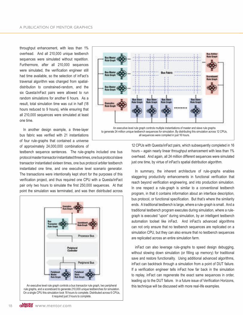
In another design example, a three-layer bus fabric was verified with 21 instantiations of four rule-graphs that contained a universe of approximately 24,000,000 combinations of testbench sequence sentences. The rule-graphs included one bus protocol master transactor instantiated three times, one bus protocol slave transactor instantiated sixteen times, one bus protocol arbiter testbench instantiated one time, and one executive level scenario generator. The transactions were intentionally kept short for the purposes of this verification project, and thus required one CPU with a Questa/inFact pair only two hours to simulate the first 250,000 sequences. At that point the simulation was terminated, and was then distributed across
12 CPUs with Questa/inFact pairs, which subsequently completed in 16 hours – again nearly linear throughput enhancement with less than 1% overhead. And again, all 24 million different sequences were simulated just one time, by virtue of inFact’s spatial distribution algorithm.
In summary, the inherent architecture of rule-graphs enables staggering productivity enhancements in functional verification that reach beyond verification engineering, and into production simulation. In one respect a rule-graph is similar to a conventional testbench program, in that it contains information about an interface description, bus protocol, or functional specification. But that’s where the similarity ends. A traditional testbench is large, where a rule-graph is small. And a traditional testbench program executes during simulation, where a rule-graph is executed “upon” during simulation, by an intelligent testbench automation toolset like inFact. And inFact’s advanced algorithms can not only ensure that no testbench sequences are replicated on a simulation CPU, but they can also ensure that no testbench sequences are replicated across an entire simulation farm.
inFact can also leverage rule-graphs to speed design debugging, without slowing down simulation (or filling up memory) for traditional save and restore functionality. Using additional advanced algorithms, inFact can backtrack through a simulation from a point of DUT failure. If a verification engineer tells inFact how far back in the simulation to replay, inFact can regenerate the exact same sequences in order, leading up to the DUT failure. In a future issue of Verification Horizons, this technique will be discussed with more real-life examples.

19
On February 18, 2008, Mentor Graphics introduced a new generation of Verification IP called Multi-View Verification Components (MVC). The MVC was created using Mentor’s unique Multi-View technology. Each MVC component is a single model that supports the complete verification effort at the system, transaction, and register transfer levels. The MVC supports automatic stimulus generation, reference checking, and coverage measurements for popular protocols, such as AMBA™ with AHB, APB/APB3, and AXI.
This article highlights the ways to create a reusable SystemVerilog and OVM-based, constrained-random verification environment for AMBA3 AXI using the AXI MVC. More detailed information can be found in the MVC Databook. MVC enables fast test development for all aspects of the AXI protocol and provides all the necessary SystemVerilog classes, interfaces, and tasks required for both directed and constrained-random testing, as required for AXI master and slave unit verification at the RTL and TLM abstraction levels.
The AXI MVC includes:
• Complete AMBA AXI protocol verification at the RTL and TLM, with stimulus generation, reference checking, and functional coverage
• Complete support of AMBA AXI protocol specification Rev 1.0 including:
-Configurable bus widths (address, read data, write data, transaction ID)
-Configurable number of concurrent burst transactions-Out-of-order transaction completion-Narrow and unaligned transfers-Illegal sequence detection-Atomic access checks
• Support for SystemVerilog, AVM, OVM, and TLM• A verification plan that helps you reach 100 percent
AMBA AXI protocol coverage• Examples of typical protocol verification tasks• Integrated transaction-based protocol debugging and analysis• Integration with QVL AXI assertion monitors optimized
for formal verification
Transaction-based verification methodologies, such as the OVM, use TLM interfaces as the communication mechanism between verification components. By using the OVM’s layered approach, the testbench code developed can be reused throughout the design cycle, lowering the overall cost typically required by RTL-oriented methodologies.
Figure 1 shows a typical configuration of the AXI MVC, along with some of the verification components delivered with the MVC (including the SystemVerilog AXI interface, driver, responder, monitor, and tasks for directed and constrained-random stimulus generation, as well as coverage groups and configuration).
Figure 1
Users of the OVM have reported a significant reduction of testbench design—around 66 percent less testbench code—yet, the SystemVerilog-based testbench provided 3-5 times more testing functionality than RTL-oriented testbenches based on proprietary languages such as vera or e. Not only do OVM testbenches require less effort to develop, ongoing support and maintenance costs are greatly reduced.
Figure 2 and figure 3 on the following page show some typical environments for master and slave unit verification enabled by the AXI MVC.
Using Questa Multi-View Verification Components and OVM for AXI Verification by Ashish Kumar, Verification Division, Mentor Graphics

20
Figure 2. Master DUT implementation
Figure 3. Slave DUT implementation
TESTBENCH EXAMPLEThe following example represents a complete constrained-random
AXI verification environment, where an RTL Verilog AXI master unit is tested by a TLM phase-level AXI slave. Any level of AXI verification can be performed easily by executing the run_test or do_test OVM methods. The example also includes QVL AXI assertion monitors that enable users to complement simulation with formal verification.
The top-level environment env instantiates the configuration class (axi_vip_config), the environment class (sample_environment), the QVL assertion monitor (qvl_monitor_wrapper), and the design as a RTL master (verilog_master_wrapper). It also configures the various components in the initial block.Below is the sample_environment class used in our example. It shows some of the internals of the AXI
MVC. The MVC library provides a number of examples of typical use-case scenarios using the various components, interfaces, and OVM methods.
module env;
parameter ADDR_WIDTH = 32; parameter RDATA_WIDTH = 32; parameter WDATA_WIDTH = 32; parameter ID_WIDTH = 2;
bit clk ; bit reset_n ; axi_vip_config #(ADDR_WIDTH, RDATA_WIDTH, WDATA_WIDTH, ID_WIDTH) axi_config;
sample_environment #(ADDR_WIDTH, RDATA_WIDTH, WDATA_WIDTH, ID_WIDTH) env;
AXI #(ADDR_WIDTH, RDATA_WIDTH, WDATA_WIDTH, ID_WIDTH) axi_if(clk, reset_n);
// User DUT verilog_master_wrapper #(ADDR_WIDTH, RDATA_WIDTH, WDATA_WIDTH, ID_WIDTH) AXI_master (.iAXI_imaster_mp(axi_if.iAXI_if.master_mp));
qvl_monitor_wrapper #(ADDR_WIDTH, RDATA_WIDTH, WDATA_WIDTH, ID_WIDTH) QVL_formal_monitor (.iAXI_if (axi_if.iAXI_if));
initial begin bit okay = 1’b0; axi_config = new (); // Master is TLM, slave is RTL axi_config.m_master_map = RTL; axi_config.m_slave_map = TLM; // VIP generates clock and reset axi_config.m_clock_source = TLM; axi_config.m_reset_source = TLM; axi_config.m_write_data_before_addr = 0; axi_config.m_write_addr_to_data_mintime = 0; axi_config.m_write_data_to_addr_mintime = 0; axi_config.per_instance =0; axi_config.coverage_name =”coverage”; axi_config.this_axi_if=axi_if; axi_config.configure_interface(okay); set_config_object(“*”,AXI_env_config,axi_config,0); env = new(“env”); if(okay == 1’b0) ovm_report_error(“env”,”Could not configure interface. Test will not run”); else env.do_test(); end
endmodule

21
class sample_environment #(int ADDR_WIDTH = 8, int RDATA_WIDTH = 8, int WDATA_WIDTH = 8, int ID_WIDTH = 4) extends ovm_env; axi_phase_responder #(ADDR_WIDTH,…) responder; axi_write_address_wait #(ADDR_WIDTH,..) write_addr_wait; axi_read_address_wait #(ADDR_WIDTH,…) read_addr_wait; axi_write_data_wait #(ADDR_WIDTH,…) write_data_wait; axi_monitor #(ADDR_WIDTH, ….) monitor; axi_wait_coverage #(ADDR_WIDTH, ….) wait_coverage; axi_transaction_coverage #(ADDR_WIDTH, …) transaction_coverage; axi_phase_coverage #(ADDR_WIDTH, …) phase_coverage; axi_phase_slave #(ADDR_WIDTH, …) slave; axi_phase_scoreboard #(ADDR_WIDTH, …) scoreboard; typedef axi_vip_config #(ADDR_WIDTH, …) axi_vip_config_t;
virtual AXI #(ADDR_WIDTH, …) axi_if;
The user typically attaches design-specific coverage objects to the monitor using the standardized features of OVM.
The OVM build() method creates the various verification components.
function void build(); super.build(); responder = new (“responder”, this); write_addr_wait = new (“write_addr_wait”, this); read_addr_wait = new (“read_addr_wait”, this); write_data_wait = new (“write_data_wait”, this); …
endfunction
OVM connect() connects the components. Note that the AXI virtual interface is already in the configuration class and can be retrieved through the OVM configuration mechanism.
function void connect(); axi_vip_config_t axi_vip_config_local; super.connect(); axi_vip_config_local = get_axi_config(); axi_if =axi_vip_config_local.this_axi_if; monitor.axi_if = axi_if; responder.axi_if = axi_if; wait_coverage.axi_if = axi_if; write_addr_wait.axi_if = axi_if;
read_addr_wait.axi_if = axi_if; write_data_wait.axi_if = axi_if; slave.axi_if = axi_if; slave.axi_write_address_port.connect( responder.axi_phase_write_address_export); …endfunction
The MVC makes it easy to add user-specific scenarios and control the randomization made. A number of SystemVerilog tasks are provided. For example:
// create random write transactions the following AXI MVC task can be usedtask rand_write_transaction( input this_axi_request_t gen= null, output this_axi_response_t resp );
// controlled read transaction used for directed teststask put_read_request( input addr_t address, input id_t id, input axi_len_e len, input axi_size_e size, input axi_prot_e prot, input axi_cache_e cache, input axi_lock_e lock, input axi_burst_e burst);
LOGGING, VISUALIZATION, AND DEBUG WITH AXI MVC
After compilation, the testbench initializes and the verification starts. If the AXI interface was configured successfully, It will be flagged by “bit ‘okay’.” As verification progresses, the MVC logs AXI transaction activity to the Questa transcript with all relevant details; such as, AXI burst mode, address, and atomic mode. The OVM reporting functionality makes it easy to control and integrate the logged information into, for example, the overall verification management environment.

22
# OVM_INFO @ 4565: env.monitor [AXI_TRANSACTION_MONITOR] (axi_transaction_mon) {# }# # ------------------------------------------------------------------------------------------------# Name Type Size Value# ------------------------------------------------------------------------------------------------# <unnamed> axi_request - @{} 18446744073709+# Transaction Type string 8 AXI_READ# Address integral 32 ‘h170# Transaction ID integral 2 ‘h1# Transaction Length string 13 AXI_LENGTH_16# Transaction Size string 11 AXI_BYTES_4# Protection Mode string 17 AXI_NORM_SEC_DATA# Cache Mode string 19 AXI_NONCACHE_NONBUF# Burst Mode string 8 AXI_INCR# Atomic Access Mode string 10 AXI_NORMAL
# ------------------------------------------------------------------------------------------------
The MVC also extends Questa’s transaction displaying capabilities with AXI protocol specific debugging, see figure 4. The MVC keeps track of any AXI protocol activity (for example, transactions started and expected responses) between any layers of the AXI protocol, enabling the user to always work at the highest level of abstraction. However, when unexpected errors occur, determining the cause and effect between high-level transactions and low-level pin-activity is greatly improved.
The AXI MVC also includes a verification plan and an open source SystemVerilog coverage object, which the user can tailor to his or her particular application to get protocol specific coverage. Figure 5 shows the verification plan and coverage model loaded into Questa’s verification management environment.
SUMMARY
With the AXI MVC, the OVM, and less than 100 lines of SystemVerilog code, users can now create a complete AMBA3, constrained-random, AXI verification environment that can be reused to verify RTL and TLM AXI master and slave units. More details on the individual capabilities of the MVC and the Questa Verification Platform can be obtained by contacting your local Mentor Graphics sales office. In an upcoming article we will show how easily the environment can be extended to include verification of AHB and APB AMBA sub-systems, creating a complete, reusable, constrained-random, AMBA SoC verification environment using OVM.

23
The engineering and computing worlds are filled with standards—from COBOL to SystemVerilog, from RS232 to AMBA. As engineers, not a day goes by when we don’t apply a standard of some sort in our work.
What makes a standard a standard? The simple but maybe not so obvious answer is that something is a standard if everyone agrees it is. Is that enough? Who is everyone? To answer these questions we’ll take a brief look at a few standards and see how they came to be considered standards.
In the functional verification world, the Open Verification Methodology (OVM) was recently released as a joint production of Cadence Design Systems and Mentor Graphics Corporation. As a verification methodology for SystemVerilog users1, OVM generated a lot of buzz at the recent DVCon conference in San Jose, CA. Although just released the first week of January 2008, as of the end of May, over 3000 people have downloaded copies. In this article we show parallels between OVM and other well known standards and argue that OVM is on the same trajectory toward standardization.
TYPES OF STANDARDSThere are four types of standards2, which break into two main
categories — de facto and de jure. De facto standards are either sponsored by a company or organization or un-sponsored. When a company makes a donation of previously proprietary technology as a standard, this would be a sponsored standard. Verilog is an example of a sponsored standard in the EDA domain. It was initially developed by Gateway Design Automation and then Cadence Design Systems. It was a de facto standard prior to Cadence’s sponsorship of it as a standard to OVI (which later became Accellera). Linux, as we will see later, is an un-sponsored de facto standard.
De jure standards can either be legally enforced or simply agreed upon. For instance, it is illegal to sell an electrical appliance in the UK that does not have a “standard” compliant plug on it, in accordance with BS 1363-4:1995. On the other hand, ASCII, the character set used by most computers, is an ANSI de jure standard; yet it would be perfectly legal to sell a computer that did not use it (though Lyndon B. Johnson would not have allowed the US government to buy such a machine). However, very few, if any, actually do.
De facto standards typically have a loyal group of users who rely on them in their work and want to see them remain viable and stable. They must be developed quickly and be responsive to change. In contrast, a de jure standard is typically developed by a committee that deliberates over the details and produces a document or other deliverable (such as a reference implementation), which represents the results of their deliberations. In both cases, the discussion and development may follow more or less rigid rules. For instance, development in the Debian branch of the Linux community is quite tightly managed even though the Linux operating system is a de facto standard.
A de facto can become a de jure standard. For example, Cadence’s Verilog language, which started as a sponsored de facto standard, is now an agreed upon de jure standard, ratified by the IEEE. In fact, this progression through the types of standards is quite common.
EXAMPLES OF STANDARDSVHDL is an example of a de jure standard. In the early 1980s, the
US government was looking for a vendor- and tool-independent HDL to enable second sourcing of IC designs. The development of the VHSIC (Very High Speed Integrated Circuit) Hardware Description Language was commissioned, and VHDL IEEE-1076-1987 was mandated by the US Department of Defense in document DOD 454 as the medium for all IC designs to be delivered as part of military contracts3.
Linux, a well known de facto standard, started its life as MINIX; a simple, UNIX-like operating system written by Andrew Tannenbaum for the purposes of educating his students about how operating systems work4. Tannenbaum made the source code (in C) freely available. Linus Torvalds was one of the people who downloaded MINIX and began to tinker with it. By 1991, he wrote his own MINIX-like OS and released it as open source code under the GNU GPL license. Linux has since grown and become an industrial-strength body of code upon which countless applications (and fortunes) have been built.
Like Verilog, the C programming language has lived its life both as a de facto standard and a de jure standard. The C language appeared in 1973 as a derivative of BCPL5. In 1978 the book The C Programming Language6 was published after C had already been in use for 5 years. It wasn’t until 1983 that ANSI formed the XJ311 committee to build a ratified standard for C. The committee finished its work in 1989, producing the
What is a Standard? by Mark Glasser, Mentor Graphics Corporation & Mark Burton, GreenSoCs

24
X3.159-1989 standard for the C language. In the approximately 16 years of its existence before becoming a ratified standard C was already one of the most important programming languages ever invented. By the time the standard was completed many millions of lines of C code were in use in production systems all across the world, many books on C were published, and the C language was already a staple of college and university computer science and engineering programs.
KEYS TO A SUCCESSFUL STANDARDHow did C and Linux become pervasive as standards without the
benefit of a recognized standards body behind them? Conversely, would VHDL have even existed, much less enjoyed any popularity as a design medium, had its use not been mandated by the US Government?
Within the story of C is a lesson about why some so-called standards fail to wear that mantel. In 1975, the US department of defense set up a “standards” organization called the High Order Language Working Group. The intent was to devise a language for use within the US government for all embedded systems. The language ADA was the result. But while ADA was a modestly popular programming language, touted as self-documenting and highly error resistant, the “standard” was short-lived as the more popular C became the de facto standard. As we have said at the top of this article, something is only a standard if everybody agrees it is. Sowa describes this phenomenon in his short article “The Law of Standards.”7
Sponsored standards often face an uphill battle for community acceptance due to a perception of openness or lack thereof. Consider, for example, Microsoft’s proposal of OOXML as an open, de facto standard A quote from Sarah Bond, platform strategy manager for Microsoft, rather understates the case. She said, “Perhaps Microsoft hasn’t communicated as best as it could have about the openness of OOXML”8.
Acceptance of a standard requires the perception, as much as the reality, of accessibility. The fear of “lock in”—whether real or imagined—can be as damaging to a fledgling standard as poor licensing. Of course this is an old story. In 1975, Sony tried to introduce a sponsored de facto standard. It offered the standard to its rivals, and while there were reports of licensing issues, what caused the demise of beta-max over the inferior VHS format seems to have more to do with perception than anything else.
As to why C and Linux became pervasive as standards without the benefit of a recognized standards body, we can observe from history that there are at least three key features of a successful standard.
1. They provide value to their users
2. They are easily accessible and applicable (well documented)
3. And…they are fun!
C and Linux, along with standards such as HTML, SMTP, XML, DNS, and a long list of many others, became de facto standards without any organization behind them or long before any standards body became interested in them because they captivated the imaginations of their users, making them fun to use!
People in search of solutions for various kinds of engineering problems, upon learning about these incipient standards, had an “aha! moment.” They quickly realized, standard or no, that these facilities provided value. They didn’t require a standards body or a government mandate to tell them this was something they needed.
For example, The C Programming Language is highly readable, a departure from the typical compiler reference manual of the time. The book presents a straightforward model of the language which is easily grasped. Readers could become reasonably proficient in C through self study. It’s not clear whether the popularity of the book caused C compilers to proliferate or whether the availability of the compiler motivated people to seek out the book. In either case, the openness of the language definition via the book and the freely available compilers contributed to the widespread proliferation of C.
The latter is another characteristic de facto standards typically have in common: they are freely available, often in open source form. It is likely that we would never have heard about Linus Torvalds or his operating system had potential users not been able to download a copy and use it. Not only could they download it freely, but because they had the source code, they could port it to various machines, augment it with new features, and fix bugs. They could not only get excited about the idea of a free UNIX-like operating system, they could control it and apply it to suit their needs.
BIRTH OF A NEW STANDARD?Clearly, OVM has captured the imagination of the verification
community. How can we account for this excitement? After all, it’s not the first entry in the SystemVerilog verification methodology arena. VMM and AVM have been available for several years and each has enjoyed success within the verification community.
It is precisely because the OVM shares many characteristics of well known de facto standards, such as C and Linux. It is available in

25
open source form under the Apache-2.0 license. This license provides protection for the copyright holders but imposes very few restrictions on its licensees. As with Linux, users can control it and modify it to suit their needs.
The OVM is supported through a unique collaboration between Cadence and Mentor Graphics, two of the largest producers of verification tools. Thus, OVM is not proprietary to any one company, which is an attractive proposition to many users. It is a sponsored de facto standard in the making. As such, we can expect it to be dynamic and its development swift. Companies that are reluctant to invest in writing code using a proprietary language or library can now avoid the problem of feeling “locked in” to a particular vendor when they use OVM.
The recent formation in Accellera of the Verification Intellectual Property Technical Subcomittee (VIP-TSC) does nothing to alter the trajectory of OVM’s rise as a de facto standard. Because OVM is open-source OVM will follow the trajectory of similar open source tools. Like the C language, OVM will ultimately be strengthened by a standardization effort by providing short-term interoperability and a longer-term migration path from other, perhaps proprietary, methodologies to the OVM.
The inevitability of OVM becoming a de facto standard for building testbenches is almost assured based on a review of the history of computing standards. History shows us that the standards that have thrived are those that effectively solve a common computing problem, are not proprietary, and are open source. Clearly OVM has achieved the market presence and momentum reflective of this pedigree, and the formation of the VIP-TSC is further evidence of this. Community participation in the formulation of a standard will protect users’ legacy investments while facilitating the growth of OVM as the de facto standard verification methodology.
Mark Glasser is a verification technologist at Mentor Graphics and Mentor’s OVM project leader. He is also one of the developers of AVM and the primary author of the AVM Verification Cookbook. Mr Glasser can be reached at [email protected].
Dr. Mark Burton is the founder and Managing Director of GreenSoCs. He is the chair of the OCP-IP SLD WG and is active in the ESL, SystemC, and Open Source communities. Dr. Burton can be reached at [email protected].
NOTES1. OVM World, http://www.ovmworld.org/
2. Takanori Ida, Evolutionary stability of de jure and de facto standard, Konan University, Faculty of Economics, http://www.econ.kyoto-u.ac.jp/~ida/3Kenkyuu/3Workingpaper/WPfile/2000-2001/standards.pdf
3. Coehlo, David R. The VHDL Handbook, Springer, 1989
4. Hasan, Ragib, The History of Linux, 2002, Department of Computer Science University of Illinois at Urbana-Champaign, https://netfiles.uiuc.edu/rhasan/linux/
5. Ritchie, Dennis, M. The Development of the C Language, 1993, http://cm.bell-labs.com/cm/cs/who/dmr/chist.html
6. Kernighan, Brian R, Ritchie, Dennis M. The C Programming Language, 1978, Prentice Hall, Englewood Cliffs, NJ
7. Sowa, John F. , The Law of Standards, http://www.jfsowa.com/computer/standard.htm
8. ZDNet, Proprietary past looms over Microsoft OOXML hopes, February 28, 2008, http://news.zdnet.co.uk/itmanagement/0,1000000308,39359136,00.htm

26
The Open Verification Methodology promotes a well defined SystemVerilog transaction-level interface, inviting integration of a host of verification technologies. Firmware has proven effective for functional verification of embedded hardware, so it follows that OVM integration of a firmware execution environment will advance the verification of embedded systems. To this end, Mentor Graphics has added OVM-compliant interfaces to the Seamless® HW/SW co-simulation tool. This article covers the firmware execution modes, supported processors, and interface points of the Seamless/OVM integration.
MAKING SEAMLESS OVM COMPLIANTSeamless supports HW/SW co-simulation by coupling a hardware
and software execution environment. Hardware is modeled in the logic simulator while software is typically run on a target instruction-set simulator (ISS) for the embedded core. The key to accelerating software execution is to isolate it from the much slower logic simulator. Much of the Seamless functionality is dedicated to this isolated, yet integrated, SW/HW execution.
The construction of Seamless processor models is key to this isolation/integration and makes possible the addition of OVM interfaces. Processor function is split down the middle with transactions connecting the two halves. The ISS executes code while the Bus Interface Model (BIM) converts these transactions to pin-level bus cycles. Most processors have multiple buses; a BIM for a given core supports all of its bus interfaces. To make Seamless OVM compliant, we’ve tapped into the transaction interface between the ISS and BIM. You can receive OVM transactions from firmware executing on the ISS, or you can connect an OVM testbench and drive transitions to the BIM where they emerge as pin-level bus cycles.
HOST-CODE EXECUTIONThere are two primary ways to execute firmware in this environment:
host-code execution and target instruction-set simulation (ISS). With host-code execution, the firmware is compiled to run native on the workstation, which most likely would be a Pentium-based machine. Seamless includes an exception handler in the form of a shared library that is linked with your firmware. Each time your code initiates a read/write access to the hardware, an exception will occur, which Seamless intercepts and routes to the design modeled in the logic simulator. This
implicit-access mode eliminates the need to call a function that explicitly sends read/write transactions to the hardware. Implicit access enables the same code to be run in simulation and on a live target without modification.
Running firmware native on the host is the fastest mode, executing at Pentium speeds of ~2 GHz. However, it’s worth noting that the logic simulator, even at the transaction level, is dramatically slower than most firmware execution modes and will dominate overall runtime.
TARGET INSTRUCTION-SET SIMULATORHost-code execution achieves speed by abstracting away any notion
of the embedded processor. A more realistic approach is to run code on a cycle-accurate ISS. Here the target compiler is used to create a binary that executes on the ISS, which accurately models structures like cache, pipelines, and tightly coupled memories. With an ISS, the user can choose to simulate instruction fetch and memory reference cycles in the hardware description or to speed execution by hiding them from the logic simulator. A cycle-accurate ISS will typically run 100K instructions/sec, much slower than running native on the host. ISS performance becomes a runtime issue only if your hardware description simulates above this speed. It requires a very abstract hardware representation to achieve 100K clocks/sec. Most hardware simulations run at a fraction of this speed.
FIRMWARE DEBUGSource-level SW debug is available for all software execution
modes. Since host-code runs native on the workstation, you can use your debugger of choice. Most instruction-set simulators include the EDGE source-level debugger. ARM models are also integrated with the RealView debugger.
In general, RTL processor models don’t support source debug, but Questa Codelink includes patented technology that delivers source-level debug for MIPS and ARM RTL processor models. Codelink adds software debug to the ModelSim/Questa user interface and connects directly to existing VMC and RTL models as delivered by ARM and MIPS. Figure 1 features a screen shot of Questa Codelink connected to an ARM 926 Design Simulation Model (DSM).
Firmware Driven OVM Testbench by Jim Kenney – SoC Verification Product Manager, Mentor Graphics

27
Figure 1: Questa Codelink source-level firmware debugger featuring Source, Callstack, Variable, and Register windows.
INTERFACING SW GENERATED CYCLES WITH THE LOGIC SIMULATOR
Read/write cycles generated by firmware and routed to the logic simulator can be applied as bus transactions or pin-level bus cycles. Seamless includes a SystemVerilog 1.0 TLM interface to connect your transaction-level bus components. For a pin-level bus interface, detailed Bus Interface Models are available for most ARM, MIPS, Freescale, IBM PowerPC, and Tensilica processors. Mixed interface simulation, where some functions connect to the processor at the transaction-level and others at pin-level, is also supported. (Figure 2). A user-defined memory map is used to route read/write cycles to the desired interface; therefore no changes to your firmware or testbench are needed to swap between transaction or pin-level stimulus.
Figure 2: Seamless OVM depicting multiple firmware execution options,
transaction and pin-level stimulus, and the Coherent Memory Server for
speeding firmware execution.
ACCELERATED MEMORY ACCESSAt the heart of Seamless is a Coherent Memory
Server. This device acts as a unique storage array for memories modeled in the logic simulator. Memories that are frequently accessed by the processor can have their storage arrays mapped to this server in place of the logic simulator’s native storage array. Firmware executing on the host or ISS can access this storage thousands of times faster than a comparable simulation memory cycle. This not only speeds firmware execution, it enables rapid initialization, loading, and examination of memories modeled in the logic simulator. For example, a dual-port video frame buffer that is loaded by the CPU and read by a HW image processor can be loaded in zero simulation time.
A user-defined memory map directs CPU memory cycles to either the memory modeled in the logic simulator or its storage array held in the Coherent Memory Server. The map can be changed on the fly during simulation. A
typical scenario is to send a few memory cycles to the logic simulator to validate the memory subsystem. These cycles are slow but necessary to insure the processor can access boot flash and main memory. From then on, this address range is served by the Coherent Memory, speeding access by three/four orders of magnitude.
Coherent Memory is available to all of the stimulus methods. While host code and an OVM testbench don’t fetch instructions and hence don’t need that function accelerated, they do load buffers in the design. Memory contents can be loaded in zero simulation time and then accessed by an IP block modeled in the logic simulator. Buffers loaded or altered by the hardware can also be examined in zero simulation time since the testbench has access to the high-speed port on the Coherent Memory Server.

28
SUPPORTED PROCESSORSMentor has developed a comprehensive offering of Seamless pro-
cessor models. Because the OVM transaction interface is implemented in the Seamless kernel and not in each processor model, all models can be used with OVM. Supported cores include the following:
• ARM7, ARM9, ARM11, and Cortex families • MIPS M4K, 4KE, 24K, 34K, and 74K• Freescale PowerPC and PowerQuicc families• Tensilica Xtensa and Diamond families
Each of these models includes an ISS, BIM, and graphical source-level debugger. All can be used to generate OVM transactions from embedded code and to convert OVM transactions to pin-level bus cycles.
SUMMARYSeamless enables straight-forward integration of firmware stimulus
into an OVM testbench. Multiple firmware execution modes provide a continuum of performance/accuracy choices. Firmware-generated stimulus can be applied to the design as transactions or pin-level bus cycles. An OVM TLM testbench can be used to drive available Bus Interface Models that convert transactions to pin-level bus cycles. Seamless supports mixed-mode stimulus where an address map applies processor cycles to the design as OVM transaction or pin-level bus cycles. Source-level firmware debug is available for all processor representations, including the Questa Codelink debugger for RTL processor models.

29
ABSTRACTThis article discusses, from a design verification engineer’s point
of view, the benefits of using Questa and the Open Verification Methodology in the verification process. This article shows how Questa and its advanced features such as integrated verification management tools and integrated transaction viewing, can help to achieve verification plan targets.
Questa also enables custom flow integration, such as the PSI-E verification management flow. Coupling with a methodology like OVM, it is possible to deliver a complete reusable verification environment in an efficient way whatever the project. OVM is a standardized verification methodology, enabling the verification environment to be reused, even in a different EDA vendor flow.
OVM provides many verification components and gives the verification engineer a way to think about how to verify and what to verify instead of thinking how to write verification components. The only things to code are drivers, which depend on the device under test. In this article, we are using a simple example: the test of an UART IP connected to the APB bus of a LEON-2 system-on-chip. We will explain how verification was done before using OVM and Hardware
Verification Language. We will then explain how OVM and Questa helps us to achieve better results while speeding-up the verification process by using the SystemVerilog DPI feature to replace the fully-functional LEON processor model and by re-using our HDL verification IPs.
OVERVIEW OF NEW QUESTA FEATURESFollowing is a very short overview of the most interesting features
for System-on-Chip verification. Questa enables transaction viewing and recording (see figure 1), achieving easier debugging of bus and protocols.
Questa comes with new verification management tools, enabling strong coupling between code coverage, functional coverage, simulation runs and verification plan. This tools support many plan file formats such as excel sheet or GamePlan file.
The latest version of Questa integrates the support for the Universal Power Format for power-aware simulation.
Design Verification Using Questa and the Open Verification Methodology: A PSI Engineer’s Point of View by Jean-Sébastien Leroy, Design Verification Engineer & Eric Louveau, Design Verification Manager, PSI Electronics

30
Figure 1-Transaction viewing in the wave window
PRESENTATION OF THE OPEN VERIFICATION METHODOLOGY
The Open Verification Methodology is the result of joint development between Cadence and Mentor Graphics. OVM is a completely open library and proven methodology based on the Universal Re-use Methodology from Cadence and on the Advanced Verification Methodology from Mentor Graphics. OVM has been developed in order to provide true SystemVerilog interoperability and to facilitate the development and usage of plug-and-play verification IP written in SystemVerilog, allowing the communication of foreign languages such as SystemC and e languages. OVM addresses some issues encountered when using proprietary languages such as:
• Different language subset• Incompatible VIP interface• Vendor-dependent library/methodology• Prohibitive licensing
OVM provides a true open-source (Apache-2.0) library and methodology written in SystemVerilog and that can run on any IEEE-1800 compliant simulator. OVM ensures interoperability across simulators and with other high-level languages and enables verification IP “plug-and-play” functionality. OVM is based on proven methodologies, URM and AVM, therefore, incorporates best practices from more than 10 years of experiences.
OVM provides base class for verification environment elements (see figure 2) such as:
• Monitor through the ovm_monitor class• Driver through the ovm_driver class• Sequencer through the ovm_sequencer class• Scoreboard through the ovm_scoreboard class• Random generator through the ovm_random_stimulus class
Figure 2-OVM library (source www.ovmworld.org)
AUTOMATED INTEGRATION OF THE VERIFICATION PLAN IN THE VERIFICATION FLOW
PSI Electronics has developed a custom verification management flow for easier and quicker verification goals achievement. This flow is based mostly on open source alternative, except for Jasper GamePlan software which is not open source but is freely available for download. The flow enables original and pleasant viewing of the verification plan using mind-mapping viewing and icon classification and provides back annotation of metrics results.
The PSI-E flow is composed of four steps:
• Moving specification and features to verify in a verification plan in FreeMind
• Converting FreeMind file format in GamePlan file format using PSI-E XSLT style-sheet
• Running simulation and retrieving coverage results in GamePlan using Questa UCDB
• Back-annotating results in FreeMind using XSLT style-sheet
The first step of the flow uses FreeMind (see figure 3), an open source Java-coded mind-mapping software.

31
Figure 3-A verification plan in FreeMind
Each key feature is classified using icons:
A property is represented using a pencil iconA testcase is represented using a wizard iconA pass result is represented using an OK iconA fail result is represented using a cancel icon A coverage result is represented using a magnifier icon An assumption is represented using an idea iconA question is represented using an help iconA high-level requirement is represented using a password icon
Notes can also be added to each feature using the post-it icon.
The second step is based on XML standard and conversion functionality. XML provides a way to convert files to another format using an XSL style-sheet based process (see figure 4).
Figure 4-XML conversion mechanism
The third step uses the Questa verification management feature to define relations between verification plan items and functional/code coverage results. This is easily done thanks to the verification management tool of Questa, able to read a GamePlan verification plan.
The last step consists of converting the annotated GamePlan verification plan back into a FreeMind map. This is done by using one more time an XSLT style-sheet.
Because all files are written using XML standard, it is possible to export back-annoted verification plan into several different file formats such as HTML for a wiki or Microsoft XML for a Word report. It is also possible to imagine a completely automatic updating of a website or a collaborative content management system.
EXAMPLE USED IN THIS ARTICLEIn this article, we will discuss previously described methods and
tools with the help of a concrete example based on a system-on-chip platform developed at PSI Electronics. This platform is based on the open-source LEON-2 processor from Gaisler, extended with custom IPs designed at PSI Electronics like VGA controller or AES cryptographic core (see figure 5). Various operating systems have been ported by PSI Electronics to this platform such as eCos or Linux.
Figure 5-PSI Electronics platform overview (source Gaisler)
We will concentrate on the UART APB slave in the following. The UART is composed of an AHB slave interface, a serial port controller for hardware flow control, a baud-rate generator and a four register, a hold receiver and a shift receiver register for the receiver side and a hold register and a shift register for the transmitter side (see figure 6).

32
Figure 6-UART block diagram (source Gaisler)
The UART contains a control register that enables the configuration device and a status register that gives information about operation of the device such as break received, overrun, parity error, transmitter hold register empty and so on.
The UART supports data frame with 8 data bits, one optional parity bit (odd or even) and one stop bit. To generate the baud-rate, the block includes a programmable 12-bits clock divider. Hardware flow control is supported through the RTSN/CTSN hand-shake signals. The UART includes a verification facility provided through a loopback mode that connects internally RXD and TXD signals together.
In order to test the IP, a verification plan has been defined in FreeMind. Each feature to verify, and corresponding testcase, have been written. Examples of tests exercised on the IP are verifying values contained at the power-up, verifying read/writing of registers, verifying transmissions for bud-rates and so on (see figure 7).
Figure 7-Verification map
HDL-BASED VERIFICATIONIn order to verify our UART, we need to exercise some stimuli to the
IP. More precisely, we need to be able to send and to receive data at different baud-rates and inject errors. This part of the job is done by a Bus Functional Model, referred as BFM in the document following. Bus functional models are simplified simulation functional models that accurately reflect the behavior of a device without modeling its internal mechanisms. One major reason to use a BFM to test the UART is that when testing using loopback mode, receiver and transmitter share the same clock and are in some sort synchronous. This can hide some bugs. With a BFM, transfers are really asynchronous and baud-rate generation bugs can be detected.
Our BFM is written in VHDL and can generate in a configurable manner all possible data frame of the protocol such as configurable baud-rate, odd/even/none parity bit, one/two stop bit. Because we need to exercise all type of stimuli to our device, our BFM can also generate false frame such as parity bit error, framing error or break. The BFM can also send text files.
The verification is done using a processor-driven methodology. We are assuming that the CPU is bug-less, or all following would be meaningless. Tests are written in ANSI-C in order to apply stimuli to the IP under test and to retrieve results.
Putting all together, we obtain a testbench that contains the system-on-chip, memory files containing data and compiled programs that will be fed in the memories and the UART BFM (see figure 8).
Figure 8-Tesbench overview

33
The processor-driven methodology has many advantages. There is no need to know or learn a verification language. You just need to have a processor and some C knowledge. By the way, the tests can be reused in other platforms and can even be used in the real chip later. But there is a real tedious and disappointing thing with processor-driven methodology. Because the processor is running, compiled C code feeds into a memory model instantiated in the top level testbench, there is no way to add breakpoints in the source code, no way to view a variable content, and by the way no source-level debug. This can be a real problem when verifying complex IP such as Ethernet PHY or MP3 decoder, especially when using pointers or complex calculation in the source code. So, before verifying the IP, we need to first debug our tests and this process can take long time.
As a feedback on our job, we are using code-coverage metrics that tell us if we are done testing the device or not. Code-coverage is a first available metric providing a measure of quality test and remaining job.
Referring to the verification map, it is evident that some conditions cannot be tested or cannot be easily tested such as low baud-rates. Moreover, a huge number of tests need to be exercised in order to exhaustively test the IP. The total number N of tests can be calculated as follow:
N = (12 bits divider) x (8 data bits) x (None, Odd, Even parity bit) x (loopback)
Replacing values, we have a number N of tests:
N = (1212) x (28) x (3) x (2) = 4096 x 2 x 256 x 3 = 6,291,456
We need to exercise more than 6 million different tests. We haven’t calculated the time necessary to complete this test but you can imagine how long it would be, especially when entering low baud-rate tests such as 1200 bps, where a bit-period is 833μs.
Using our flow, we can greatly reduce the number of tests to be exercised and, by the way, the time needed to simulate. Tests can first be reduced by constraining the search space. For example, only standard baud rates such as 9600 bps, 19200 bps, 57600 bps and so on are interesting to be verified. Then setting-up RTL code coverage and integrated PSI-E flow helps to reduce the number of tests and the
time consumed to verify the design. Targeting 100% of code coverage gives a feedback on when we are done so that not all tests need to be exercised to be sure that the IP has been fully exercised. Moreover automatic results reporting reduces the amount of time spent to annotate the verification plan. In fact, all coverage and pass/failed results are automatically reported in the right place in the verification plan and the end of the tests. Then, any format of document can be generated: a back-annotated FreeMind map, a word report and even an automatic wiki report.
But VHDL isn’t a verification language and setting up a complex environment for a complete SoC is a pain. For example, replacing the processor by a bus functional model requires a lot of coding and debugging time. VHDL doesn’t provide transaction-level modeling nor a simple way to do constraint random verification. But all of these can be done using VHDL if desired, but at the price of consuming a lot of time, not to mention forgetting about re-use. What you will finally have is a sort of custom and proprietary verification language based on VHDL and command files that only your BFM can work with.
VERIFICATION USING HVL AND OVMOn the other hand, OVM greatly helps verification efficiency and
productivity by enabling verification IP re-use while providing a very powerful environment. A good way to start with OVM is to read the Advanced Verification Methodology book from Mentor Graphics as well as the Universal Re-use Methodology guide from Cadence.
The first step is to move the VHDL top level testbench to SystemVerilog. This can be quickly achieved by re-using all VHDL models (memory, bfm …) and re-instantiating them into a SystemVerilog top. Re-using components is really a great deal because it speeds up the process to have a working environment while enabling one to re-use working complex models that are already coded. Here, a sanity check can be launched to ensure that all is working properly like the old VHDL testbench.
The next step is to setup OVM. An OVM environment is basically made by inheriting provided classes. The only class to overload is the ovm_driver one to adapt it to the device(s) under test. Thanks to the object-oriented structure of SystemVerilog, only the printing method and low-level signals driving methods need to be coded, since other useful functions are already being provided by the class members methods.
So we have here a first SystemVerilog/OVM environment. But in this environment, we are always using VHDL models, such as memory models, to have the system-on-chip running. While OVM enables re-

34
using VHDL verification components, it would be better to have them all coded in SystemVerilog, especially due to limitations inherent to VHDL such as no hierarchical path. A way to have a SystemVerilog only environment would be to rewrite all memory models, all clock generators, all verification IP and all bus functional models in SystemVerilog but this is a time consuming process due to coding and debugging new models.
Because we are looking for ways to speed up the process while maintaining high verification quality and re-use, at PSI Electronics we have sought to reduce the time spent writing code. We have found a solution by keeping our UART BFM, in order to reduce the time we’d spend to write a new one, with the SystemVerilog Direct-Programming Interface. Using DPI, we just need to write a master AHB bus functional model which will be driven with already-coded C tests (almost the same one that was used in the VHDL testbench). In that case, the verification process and environment setup time is greatly reduced because we don’t need processor program memory models for example.
By the way, we do not need to write and debug all models. Just the minimum necessary models are translated into SystemVerilog. In that case, only the AHB BFM needs to be programmed. So, we are working with a verification environment that is bug-free quickly, enabling faster and better verification results. We can then concentrate on translating all our models into SystemVerilog while being able to achieve good verification in the mean time.
CONCLUSIONMixing OVM, SystemVerilog and Questa together is a powerful and
efficient way of achieving reliable design verification. Questa provides the verification engineer with many features that help debugging and managing simulation such as transaction viewing, memory content viewing and modifying, custom radix definition or verification management tools. With these features, it is possible to integrate a custom flow, such as the one used by PSI Electronics, and in that way to achieve automatic tasks.
As shown, using FreeMind and XML standards permit you to build friendly verification management flows. About the methodology and the mechanism: HDL shows its limits quickly when thinking about re-using or complex devices-under-test. It is always possible to develop complex environments and to make complex scenarios evolving random-constraint verification or transaction-level modeling but this is costly. For this reason, OVM and SystemVerilog is a good alternative. OVM provides a ready-made solution to set up a complex but reliable and re-usable verification environment. OVM is shipped with a huge number of methods and components that enable the verification engineer to quickly develop complex and reliable verification environments and to setup complex scenarios on a complex design.

35
INTRODUCTIONThis is the first in a series of articles helping you get started with
OVM, the Open Verification Methodology for functional verification using SystemVerilog. OVM is supported by a library of SystemVerilog classes. The emphasis in these articles is on getting your code to run, while at the same time coming to understanding more about the structure and purpose of the OVM classes.
OVM was created by Mentor Graphics and Cadence based on existing verification methodologies originating within those two companies, including Mentor’s AVM, and consists of SystemVerilog code and documentation supplied under the Apache open-source license. The official release can be obtained from the website, www.ovmworld.org. The overall architecture of OVM is well described in the Datasheet and White Paper available from that website.
This article assumes you have at least some familiarity with SystemVerilog, with constrained random simulation, and with object-oriented programming.
OVM IN A NUTSHELLIf you currently run RTL simulations in Verilog or VHDL, you can
think of SystemVerilog and OVM as replacing whatever language and coding style you use for your test benches. But OVM test benches are more than traditional HDL test benches, which might wiggle pins on the design-under-test (DUT) and rely on the designer to inspect a waveform diagram to verify correct operation. OVM test benches are complete verification environments composed of reusable verification components, and used as part of an overarching methodology of constrained random, coverage-driven, verification.
The key objectives of OVM are to enable productivity and verification component reuse within the verification environment. This is achieved through the separation of tests from the test bench, through having standardized conventions for assembling verification components, through allowing verification components to be highly configurable, and through the addition of automation features not provided natively by SystemVerilog.
GETTING INTO THE OVM CODEThe OVM 1.0.1 release includes two top-level directories, ./src and
./examples, which contain the source code for the OVM library and a set of examples, respectively. The source code is structured into subdirectories, but you can ignore this for now. The ./src directory contains a number of header files supporting several compilation strategies.
In order to compile OVM applications using Questa, the approach we recommend is:
• to add ./src to the include path on the command line, that is,
+incdir+/.../src
• to add ./src/ovm_pkg.sv to the front of the list of files being compiled
• to add the following lines to your various SystemVerilog files
// At the top of each file`include “ovm_macros.svh”
// Within any modules or packages
import ovm_pkg::*;
Make sure that if you put ovm_pkg.sv on the command line as suggested above, you do not include the header “ovm.svh” in the source files.
The ./examples directory tree in the OVM release contains sample script files that can be modified to compile your code.
THE VERIFICATION ENVIRONMENTThis article shows a very simple example including a design-under-
test, a verification environment (or test bench), and a test. Assuming you have written test benches in VHDL or Verilog, the structure should be reasonably obvious. The SystemVerilog code is structured as follows:
- Interface to the design-under-test
- Design-under-test (or DUT)
A Practical Guide to OVM – Part 1by John Aynsley, CTO, Doulos

36
- Verification environment (or test bench) - Transaction - Driver - Top-level of verification environment
- Instantiation of stimulus generator - Instantiation of driver
- Top-level module - Instantiation of interface - Instantiation of design-under-test - Test, which instantiates the verification environment - Process to run the test
Since this example is intended to get you started, some pieces of the jigsaw are missing, most notably a verification component to perform checking and collect functional coverage information. It should be emphasized that the purpose of this article is not to demonstrate the full power of OVM, but just to get you up-and-running.
CLASSES AND MODULESIn traditional Verilog code, modules are the basic building block used
to structure designs and test benches. Modules are still important in SystemVerilog and are the main language construct used to structure RTL code, but classes are also important, particularly for building flexible and reusable verification environments and tests. Classes are best placed in packages, because packages enable re-use and also give control over the namespaces of the SystemVerilog program.
The example shown here includes a verification environment consisting of a set of classes, most of which are placed textually within a package, a module representing the design-under-test, and a single top-level module coupling the two together. The actual link between the verification environment and the design-under-test is a SystemVerilog interface.
HOOKING UP THE DUTThe SystemVerilog interface encapsulates the pin-level connections
to the DUT.
interface dut_if();
int addr; int data; bit r0w1;
modport test (output addr, data, r0w1); modport dut (input addr, data, r0w1);
endinterface: dut_if
Of course, a real design would have several far more complex interfaces, but the same principle holds. Having written out all the connections to the DUT within the interface, the actual code for the outer layer of the DUT module becomes trivial:
module dut(dut_if.dut i_f); ...endmodule: dut
As well us removing the need for lots of repetitive typing, interfaces are important because they provide the mechanism for hooking up a verification environment based on classes. In order to mix modules and classes, a module may instantiate a variable of class type, and the class object may then use hierarchical names to reference other variables in the module. In particular, a class may declare a virtual interface, and use a hierarchical name to assign the virtual interface to refer to the actual interface. The overall structure of the code is as follows:
package my_pkg; ... class my_driver extends ovm_driver; ... virtual dut_if m_dut_if; ... endclass
class my_env extends ovm_env; my_driver m_driver; ... endclass ...endpackagemodule top; import my_pkg::*;
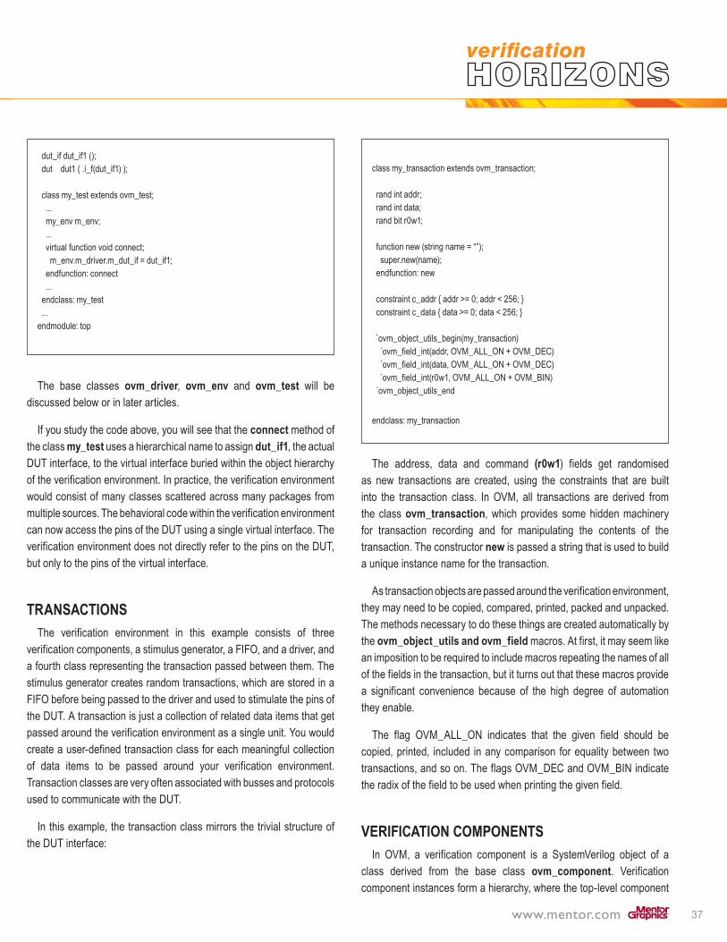
37
dut_if dut_if1 (); dut dut1 ( .i_f(dut_if1) );
class my_test extends ovm_test; ... my_env m_env; ... virtual function void connect; m_env.m_driver.m_dut_if = dut_if1; endfunction: connect ... endclass: my_test ...endmodule: top
The base classes ovm_driver, ovm_env and ovm_test will be discussed below or in later articles.
If you study the code above, you will see that the connect method of the class my_test uses a hierarchical name to assign dut_if1, the actual DUT interface, to the virtual interface buried within the object hierarchy of the verification environment. In practice, the verification environment would consist of many classes scattered across many packages from multiple sources. The behavioral code within the verification environment can now access the pins of the DUT using a single virtual interface. The verification environment does not directly refer to the pins on the DUT, but only to the pins of the virtual interface.
TRANSACTIONSThe verification environment in this example consists of three
verification components, a stimulus generator, a FIFO, and a driver, and a fourth class representing the transaction passed between them. The stimulus generator creates random transactions, which are stored in a FIFO before being passed to the driver and used to stimulate the pins of the DUT. A transaction is just a collection of related data items that get passed around the verification environment as a single unit. You would create a user-defined transaction class for each meaningful collection of data items to be passed around your verification environment. Transaction classes are very often associated with busses and protocols used to communicate with the DUT.
In this example, the transaction class mirrors the trivial structure of the DUT interface:
class my_transaction extends ovm_transaction; rand int addr; rand int data; rand bit r0w1; function new (string name = “”); super.new(name); endfunction: new constraint c_addr { addr >= 0; addr < 256; } constraint c_data { data >= 0; data < 256; } `ovm_object_utils_begin(my_transaction) `ovm_field_int(addr, OVM_ALL_ON + OVM_DEC) `ovm_field_int(data, OVM_ALL_ON + OVM_DEC) `ovm_field_int(r0w1, OVM_ALL_ON + OVM_BIN) `ovm_object_utils_end
endclass: my_transaction
The address, data and command (r0w1) fields get randomised as new transactions are created, using the constraints that are built into the transaction class. In OVM, all transactions are derived from the class ovm_transaction, which provides some hidden machinery for transaction recording and for manipulating the contents of the transaction. The constructor new is passed a string that is used to build a unique instance name for the transaction.
As transaction objects are passed around the verification environment, they may need to be copied, compared, printed, packed and unpacked. The methods necessary to do these things are created automatically by the ovm_object_utils and ovm_field macros. At first, it may seem like an imposition to be required to include macros repeating the names of all of the fields in the transaction, but it turns out that these macros provide a significant convenience because of the high degree of automation they enable.
The flag OVM_ALL_ON indicates that the given field should be copied, printed, included in any comparison for equality between two transactions, and so on. The flags OVM_DEC and OVM_BIN indicate the radix of the field to be used when printing the given field.
VERIFICATION COMPONENTSIn OVM, a verification component is a SystemVerilog object of a
class derived from the base class ovm_component. Verification component instances form a hierarchy, where the top-level component

38
or components in the hierarchy are derived from the class ovm_env. Objects of type ovm_env may themselves be instantiated as verification components within other ovm_envs. You can instantiate ovm_envs and ovm_components from other ovm_envs and ovm_components, but the top-level component in the hierarchy should always be an ovm_env.
A verification component may be provided with the means to communicate with the rest of the verification environment, and may contain a set of standard methods that implement the various phases of elaboration and simulation. One such verification component is the driver, which is described here line-by-line:
class my_driver extends ovm_driver;
ovm_driver is derived from ovm_component, and is the base class to be used for user-defined driver components. There are a number of such methodology base classes derived from ovm_component, each of which have a name suggestive of their role. Some of these classes add very little functionality of their own, so it is also possible to derive the user-defined class directly from ovm_component (or from ovm_threaded_component – see below).
ovm_get_port #(my_transaction) get_port;
The get_port is the means by which the driver communicates with the stimulus generator. The class ovm_get_port represents a transaction-level port that implements the get(), try_get() and can_get() methods. These methods actually originated as part of the SystemC TLM-1.0 transaction-level modeling standard. The driver calls these methods through this port to fetch transactions of type my_transaction from the stimulus generator.
virtual dut_if m_dut_if;
The virtual interface is the means by which the driver communicates with the pins of the DUT, as described above.
`ovm_component_utils(my_driver)
The ovm_component_utils macro provides factory automation for the driver. The factory will be described in a later article, but this macro plays a similar role to the ovm_object_utils macro we saw above for the transaction class. The important point to remember is to invoke this macro from every single verification component; otherwise, bad things happen.
function new(string name, ovm_component parent); super.new(name, parent);
endfunction: new
The constructor for an ovm_component takes two arguments, a string used to build the unique hierarchical instance name of the component and a reference to the parent component in the hierarchy. Both arguments should always be set correctly, and the user-defined constructor should always pass its arguments to the constructor of the superclass, super.new.
function void build; super.build(); get_port = new(“get_port”, this);
endfunction : build
The build method is the first of the standard hooks called back in each of the phases of elaboration and simulation. The build phase is when all of the verification components get instantiated. This build method starts by calling the build method of its superclass, as build methods always should, then instantiates the get port by calling its constructor new. This particular component has no other child components, but if it did, they would be instantiated here.
virtual task run; forever begin my_transaction tx; #10 get_port.get(tx);
ovm_report_message(“”,$psprintf( “Driving cmd = %s, addr = %d, data = %d}”, (tx.r0w1 ? “W” : “R”), tx.addr, tx.data)); m_dut_if.r0w1 = tx.r0w1; m_dut_if.addr = tx.addr; m_dut_if.data = tx.data; endendtask: run
endclass: my_driver

39
The run method is another standard callback, and contains the main behavior of the component to be executed during simulation. Actually, run does not belong to ovm_component but to ovm_threaded_component. Only threaded components have a run method that is executed during simulation. This run method contains an infinite loop to get the next transaction from the get port, wait for some time, then wiggle the pins of the DUT through the virtual interface mentioned above.
People sometimes express discomfort that this loop appears to run forever. What stops simulation? There are two aspects to the answer. First, get is a blocking method. The call to get will not return until the next transaction is available. When there are no more transactions available, get will not return, and simulation is able to stop due to event starvation. Secondly, it is possible to force simulation to stop, despite the existence of such infinite loops, by calling the method global_stop_request or by setting a watchdog timer using the method set_global_timeout.
The run method also makes a call to ovm_report_message to print out a report. This is a method of the report handling system, which provides a standard way of logging messages during simulation. The first argument to ovm_report_message is a message type, and the second argument the text of the message. Report handling can be customised based on the message type or severity, that is, information, warning, error or fatal. ovm_report_message generates a report with severity OVM_INFO.
NEXT STEPSIn this article we have examined the OVM verification environment,
transactions and verification components. We will pick up the story again in subsequent articles, where we will explore OVM simulation phases, tests, configuration, sequences, and the factory. In the meantime, you can download the source code for this and other examples from www.doulos.com/knowhow.
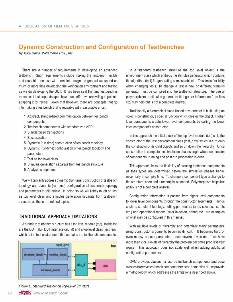
40
There are a number of requirements in developing an advanced testbench. Such requirements include making the testbench flexible and reusable because with complex designs in general we spend as much or more time developing the verification environment and testing as we do developing the DUT. It has been said that any testbench is reusable; it just depends upon how much effort we are willing to put into adapting it for reuse! Given that however, there are concepts that go into making a testbench that is reusable with reasonable effort.
1. Abstract, standardized communication between testbench components
2. Testbench components with standardized API’s3. Standardized transactions4. Encapsulation5. Dynamic (run-time) construction of testbench topology6. Dynamic (run-time) configuration of testbench topology and
parameters7. Test as top level class8 .Stimulus generation separate from testbench structure9. Analysis components
We will primarily address dynamic (run-time) construction of testbench topology and dynamic (run-time) configuration of testbench topology and parameters in this article. In doing so we will lightly touch on test as top level class and stimulus generation separate from testbench structure as these are related topics.
TRADITIONAL APPROACH LIMITATIONSA standard testbench structure has a top level module (top). Inside top
are the DUT (alu), DUT interface (alu_if) and a top level class (test_env) which is the test environment that contains the testbench components.
Figure 1: Standard Testbench Top-Level Structure
In a standard testbench structure the top level object is the environment class which embeds the stimulus generator which contains the algorithm (test) for generating stimulus objects. This limits flexibility when changing tests. To change a test a new or different stimulus generator must be compiled into the testbench structure. The use of polymorphism or stimulus generators that gather information from files etc. may help but is not a complete answer.
Traditionally a hierarchical class-based environment is built using an object’s constructor, a special function which creates the object. Higher level components create lower level components by calling the lower level component’s constructor.
In this approach the initial block of the top level module (top) calls the constructor of the test environment class (test_env), which in turn calls the constructor of its child objects and so on down the hierarchy. Once construction is complete the simulation phases begin where connection of components, running and post run processing is done.
This approach limits the flexibility of creating testbench components as their types are determined before the simulation phases begin, essentially at compile time. To change a component type a change to the structural code and a recompile is needed. Polymorphism helps but again is not a complete answer.
Configuration information is passed from higher level components to lower level components through the constructor arguments. Things such as structural topology, setting parameters (array sizes, constants etc.) and operational modes (error injection, debug etc.) are examples of what may be configured in this manner.
With multiple levels of hierarchy and potentially many parameters, using constructor arguments becomes difficult. It becomes hard or even messy to pass parameters down several levels and if we have more than 2 or 3 levels of hierarchy the problem becomes progressively worse. This approach does not scale well when adding additional configuration parameters.
OVM provides classes for use as testbench components and base classes to derive testbench components whose semantics of use provide a methodology which addresses the limitations described above.
Dynamic Construction and Configuration of Testbenchesby Mike Baird, Willamette HDL, Inc.

41
TEST AS TOP LEVEL CLASS.OVM provides a means for separating the stimulus generation
algorithm (test) from the test bench structure through layered stimulus (scenarios) or sequences. This allows us to have a structure where a “test” class is the top level object instead of the environment class. The test or stimulus generating object is contained within this top level class and is not a testbench component. In Figure 2 the MAC_scenario is a stimulus generation object. It is a scenario and implements a multiply accumulate algorithm.
Figure 2: Test as Top Level Class
DYNAMIC (RUN-TIME) CONSTRUCTION OF TESTBENCH COMPONENTS
A well known object oriented best practice (pattern) is called the factory pattern. A factory is a class that creates objects dynamically. Its main benefit is the type of object that is created is specified at run time. OVM provides a factory that can create any type of transaction or any testbench component that is registered with this factory. The OVM factory is not part of the testbench component hierarchy but rather a static object that exists outside of the hierarchical structure.
To register a class with factory requires the addition of a property and a method in the class declaration. This property is a specialization of a registry class (a library base class). The method (get_type_name()) that is added returns a string which identifies the type of the class. Optionally there is a macro provided for registration. Each class is registered with an associated string which is used to lookup or index the class in the factory.
Creation of a testbench component object is done by calling a factory method (create_component()), while a second factory method (create_object()) is provided for creation of stimulus objects. These methods create the requested object and return a handle to the object to the calling component.
OVM simulation has a number of phases that could be grouped into three general activities.
• Elaboration – phases for building and connecting the testbench components.
• Run – phase for generation and application of stimulus and checking of results.
• Post run – phases for cleanup and reporting.In the methodology using the factory, a testbench component does
not create a child component in its constructor. Rather all the testbench components create child components dynamically in the build phase using the factory. The build phase is part of the elaboration activities and is the first post-new phase, that is it is the first phase that occurs after the creation of the top level class. During the build phase, the top level test class creates the environment class object using the factory, which in turn creates its child components using the factory and so on.
During the run phase of simulation the factory may be used to create stimulus objects as opposed to calling the constructor directly to create the stimulus object.
THE POWER OF THE FACTORY COMES TO LIFE WITH FACTORY OVERRIDES.
Factory overrides may be set up to dynamically change the type of object the factory constructs. With a factory override the factory is modified such that when one type of object is requested from the factory it returns a second or substitute type of object instead. The second type must be type compatible with the original type. Typically it is a derived type. An override may be further restricted by specifying not only the type that will be overridden but the instance path where the type may be replaced. This allows for instance specific overrides in addition to general type overrides.
A factory override may be set up at any time during the simulation. Typically however they are set up during the build phase and most often in the build phase of the top level class prior to the construction of the test environment.
Figure 3: Factory overrides in Test

42
In that arrangement the test customizes the test environment structure to what is required by the test through factory overrides. An example is the MAC_scenario test requires a driver transactor which provides feedback from the ALU DUT to the MAC_scenario in order to implement the multiply accumulate. Other tests that simply generate arithmetic operations to the ALU may not require a feedback path from the DUT and would use a different driver transactor. Each test can specify using factory overrides which type of driver to create in the testbench structure. Another example is the test may have an override which specifies the type of stimulus object that is generated for the DUT. This approach allows each test to be run, with each one dynamically configuring the testbench structure using the factory and specifying the type of stimulus object, without re-compiling!
DYNAMIC (RUN-TIME) CONFIGURATION OF TESTBENCH TOPOLOGY AND PARAMETERS
OVM has an alternate approach for providing information from a higher level component to a lower level component which avoids the need to pass information through constructor arguments. Indeed the OVM factory does not allow for additional constructor arguments beyond what is required by the library itself (a name and parent argument) so this alternate approach is required when using the factory!
The alternate approach provides for configuration data to be stored at each level of the hierarchy. A higher level component influences a lower level component by setting configuration data which may be retrieved and used by a lower level component. API methods are provided for setting and retrieving configuration data.
Configuration data may be in the form of an integer value, a string or an object. An object may be used to encapsulate data that is not an integer value or string. The higher level component stores the data with a unique lookup string and further specifies an OVM hierarchical path relative to itself, specifying which of the lower level components in its sub hierarchy is allowed to access this data. The lower level component retrieves data using the lookup string. Its search for the data begins at the top in the global space and proceeds down the hierarchical path to the component. It retrieves the data at the first successful match it finds. Wildcarding is allowed in both the lookup string and the path to provide flexibility in setting and getting data.
Configuration data may be set at anytime during simulation. Typically it is set and retrieved during the build phase. It is common to set configuration data with regards to the testbench structure in the build phase of the test class.
Figure 4: Test Environment Configurations in Test
An example of the use of an object configuration data is to encapsulate a virtual interface. A container class may be created with a property of type virtual interface (virtual alu_if). An object of this type is created in the top level module and its virtual interface property set to the interface (alu_if). This object is then placed into the global configuration data and set to be retrieved by any class object, such as a driver or monitor transactor that requires a virtual interface connection to the DUT. This avoids the messy approach of creating virtual interface properties at all levels of the hierarchy and passing the virtual interface connection down through the hierarchy.
CONCLUSIONThe semantics of use of the classes in the OVM library define a
methodology which allows for dynamic (run-time) configuration and construction of the test environment. This, together with other features, provides for greater flexibility in testbench construction and a higher degree of reuse.
With the top level class being a test, using test environment configuration data together with test factory overrides provides each test with the flexibility to configure the test environment to its requirements. Once all the test bench component classes, stimulus classes and tests have been compiled, different tests can be run without recompiling.

43
Mike Baird has 26 years of industry experience in hardware design and verification. He is the author and an instructor of Willamette HDL’s OVM training course. He has 15 years experience teaching design and verification languages including Verilog, SystemVerilog, OVM, C++ and SystemC. He is the founder of Willamette HDL (1993 – Present)
Willamette HDL, Inc. (WHDL) is a leading provider of design and verification training in the U.S. and around the world. Founded in 1993, it has an extensive offering of technology training for SystemVerilog, the Open Verification Methodology (OVM), SystemC, Verilog and VHDL. Willamette is based in Beaverton, OR (503) 590-8499, www.whdl.com.

44
INTRODUCTIONVerification of a chip is easily the most time-consuming task
confronting the product team. Increasingly, verification engineers are using innovative technologies and newer methodologies to achieve satisfactory functional verification. SystemVerilog is fast becoming the language of choice for implementing verification projects. Its rich set of verification-friendly constructs, IEEE standard status, and universal support across multiple vendor platforms warrants its overwhelming acceptance.
Verification-specific constructs in SystemVerilog include object-oriented data structures, support for constrained random stimulus generation, assertion specification and functional coverage modeling. The Open Verification Methodology (OVM) uses the latest SystemVerilog constructs to provide users with a powerful verification infrastructure. OVM-based team will benefit greatly from productivity solutions that will analyze user files for errors in use model/implementation as well as provide ways to better understand OVM methodology and hierarchy.
VeriEZ’s EZVerify is a unique tool suite that offers OVM users a static analysis tool (EZCheck) to perform over 30 OVM rule-checks and a knowledge extraction tool (EZReport) to create persistent documents that outline hierarchy and connectivity.
EZVERIFY – BACKGROUNDEREZVerify is the industry’s first SystemVerilog productivity solution to
provide static analysis capability for design, assertions and testbench capabilities as described in the IEEE 1800 standard. Its main capabilities are:
• Identifying coding errors early in the flow, giving beginner and experienced users alike the opportunity to fix such errors with EZCheck, a programmable static linter for HDL-based modules
• Providing comprehensive documentation of design and verification information by analyzing the input modules (new, legacy or external IP).
SystemVerilog projects are complex and the modules in a typical HDL-based project can easily amount to thousands of lines of code. In addition, projects invariably include multi-person geographically
dispersed teams. It is not enough to have unwritten rules and policies for such projects. It is imperative that companies have corporate-wide enforceable policies to meet aggressive time-to-market schedules while continuing to develop consistent and reusable code.
EZVerify aims to enable efficient design and verification by providing innovative tools that fit into a typical design flow, while targeting specifically methods for detecting errors in design and verification code, and for promoting reuse.
EZCHECK – STATIC ANALYSIS
Figure 1 : EZCheck Use Model
EZCheck is a static analysis utility for SystemVerilog modules. On the design front, it can detect problems such as latch inference, race-prone implementation and areas leading to synthesis/simulation discrepancies. On the verification front, it can detect problems such as erroneous usage of concurrency constructs, missing function output assignments, and several other serious errors that are not normally uncovered without several hours of debugging.
EZCHECK: RULESETSA collection of rules, or a ruleset, is the primary input to EZCheck.
A rule can be thought of as a well-defined check; over and beyond the syntax and semantics of the language. For e.g., a missing semicolon
OVM Productivity using EZVerifyby Sashi Obilisetty, VeriEZ

45
is a “syntax check” that will be identified by all parsers. Imposing a restriction on the usage of certain constructs, however, is a “rule check”. EZCheck comes standard with several rulesets, each of which addresses best practices in various domains of SystemVerilog, such as Functional Coverage, Assertions, Design and Verification.
Figure 2: Available Rulesets in EZCheck
Rulesets are ASCII files that can be created using any standard text editor. Rules are selected and customized in a ruleset. Rules can be added and customized by setting appropriate values for various rule attributes.:
• Name: The name of the rule to be added; a different user-supplied rule name may be bound to the predefined rule name. If a user-supplied name exists, all violations and messages will use the user-supplied name.
For example, the following entry binds the predefined rule name ‘ValidPrintAndScanFunction’ to the user-supplied name ‘SafeFunctionCall’. The prefix ‘N’ is used to identify the entry as a rule name attribute.
------------------------------------------------------------------------N:ValidPrintAndScanFunction:SafeFunctionCall
------------------------------------------------------------------------
• Value(s): Values are specified using the prefix ‘V’. Values may be user-selectable or user-specified. An example of a rule with user-selectable values is “SyncControl” with user-selectable strings “ALL”, “ANY”, “ORDER” or “CHECK”. For this rule, the user may select one or more of the user-selectable strings as appropriate controls for the “sync” call. An example of a rule with user-specified values is “ProgramName”, which accepts regular expression syntax for valid program names.
The following entries show examples of rule value specifications:
------------------------------------------------------------------------#SyncControl rule with user-selectable string ‘ALL’N:SyncControlV:ALL
#ProgramName rule, should start with uppercase, and end with _prgN:ProgramNameV:^[A-Z][A-Za-z]*_prg
------------------------------------------------------------------------
• Hint: The optional hint attribute is specified using the ‘H’ prefix. All rules may have hints.
The following entry shows a rule with the optional hint attribute:
------------------------------------------------------------------------#SyncControl rule with user-selectable string ‘ALL’N:SyncControlV:ALLH: Using ‘ALL’ options prevents deadlocks
------------------------------------------------------------------------
• Severity: The optional severity attribute uses the ‘S’ prefix and takes any string as its value. Typically, users will define a few severity levels and assign these levels to the rules.
The following entry shows rules with 2 severity levels, ERROR and WARNING:
------------------------------------------------------------------------#SyncControl rule with user-selectable string ‘ALL’N:SyncControlV:ALLS:ERROR
#ProgramName rule, should start with uppercase, and end with _prgN:ProgramNameV:^[A-Z] [A-Za-z]*_prgS:WARNING------------------------------------------------------------------------

46
• Category: The optional category attribute ‘C’ is used to categorize rules. Category names may be any user-specified strings. Typically, user will predetermine the categories to be used and place rules in appropriate categories.
The following entry shows rules in 2 categories, Naming and Coding.
------------------------------------------------------------------------#SyncControl rule with user-selectable string ‘ALL’N:SyncControlV:ALLC:Coding
#ProgramName rule, should start with uppercase, and end with _prgN:ProgramNameV:^[A-Z][A-Za-z]*_prgC:Naming------------------------------------------------------------------------
EZREPORT – KNOWLEDGE EXTRACTIONEZReport creates a comprehensive document that summarizes a
given HDVL module. It is useful to understand external verification IP and legacy IP. Verification engineers can make reuse decisions by using the comprehensive document created by EZReport.
Users may also customize the document created to include additional proprietary information such as links to specific files and illustrations. Information provided by EZReport includes:
• Top-level view• Global variables and subroutines• Object and method hierarchy• Class data, including constraints and coverage models
EZReport also provides an interface to the popular Doxygen documentation system.
Figure 3 : EZReport Use Model
OVM PRODUCTIVITY WITH EZVERIFYEZVerify can enable productivity for OVM-based teams by checking
for errors in OVM usage and providing an easy mechanism to understand and apply the hierarchy present in OVM-based projects. A snapshot of the hierarchy created by EZReport is shown in Figure 4 (at right).
The rest of this section is devoted to EZCheck usage by utilizing the OVM ruleset.
The OVM ruleset has four basic types of rules:
Object Design Rules: The Object Design Rules are used to specify methods (SystemVerilog tasks or functions) that should be implemented for specific OVM objects for creating reusable verification modules. Required methods can be specified for sub-classes of the following OVM objects:
• ovm_agent• ovm_driver• ovm_env• ovm_monitor• ovm_object• ovm_sequence• ovm_sequence_item• ovm_sequencer• ovm_scoreboard• ovm_test• ovm_transaction

47
Figure 4: OVM Hierarchy created with EZReport
OVM Best Practices: The OVM Best Practices rules concentrate on recommendations provided by OVM tutorials for putting together a robust and reusable verification environment. They include rule checks for recommended macro calls (for e.g., looking for the usage of the ‘ovm_field_int’ macro).
Connectivity Rules: Connectivity rules focus on ensuring that valid connections exist between the DUT and verification environment, as well as the various verification components. Rules include checks for ensuring that guidelines specified for the ‘connect()’ callback are satisfied (for e.g., looking to ensure that producers and consumers are connected).
Verification Environment Rules: These rules are designed to provide compelling value by checking for classic lint-style errors. Rules include checks for the following occurrences in SystemVerilog code:
• Missing calls to super.() method, when applicable• Creation of related sub-classes using the recommended ‘create_component’ method from the ovm_factory• Global timeouts are specified for individual tests using recommended OVM routines
Some of the errors highlighted by the EZCheck OVM rule-checker for verification code are shown below:
//Environment Class created by the end-user
class xbus_env extends ovm_env;
// Virtual Interface variable protected virtual interface xbus_if xi0;
// Control properties protected bit has_bus_monitor = 1; protected int unsigned num_masters = 0; protected int unsigned num_slaves = 0;
// The following two bits are used to control whether checks // and coverage are // done both in the bus monitor class and the interface. bit intf_checks_enable = 1; bit intf_coverage_enable = 1;
// Components of the environment xbus_bus_monitor bus_monitor; xbus_master_agent masters[]; xbus_slave_agent slaves[];
// Provide implementations of virtual methods such as get_type_name //and create `ovm_component_utils_begin(xbus_env) `ovm_field_int(has_bus_monitor, OVM_ALL_ON) `ovm_field_int(num_masters, OVM_ALL_ON) `ovm_field_int(num_slaves, OVM_ALL_ON) `ovm_component_utils_end
// build function void build(); string inst_name; if(has_bus_monitor == 1) begin bus_monitor = new xbus_bus_monitor(“xbus_monitor”); end slaves = new[num_slaves]; for(int i = 0; i < num_slaves; i++) begin $sformat(inst_name, “slaves[%0d]”, i); $cast(slaves[i], create_component(“xbus_slave”, inst_name)); end endfunction : build
endclass
Missing ovm_field_int
macro calls to ‘intf_
checks_enable’ and
‘intf_coverage_enable
Monitor creation
missing recommended
ovm_factory:: create_
component call
String ‘xbus_slave” does
not match the name of the
corresponding component
‘xbus_slave_agent’
super.build() missing
in build method
‘xbus_env’ missing
a constructor

48
CONCLUSIONProductivity is one of the most important criteria used by end-users
when evaluating new methodologies. OVM promises a high productivity environment for verification engineers. Adoption of a new methodology comes with its challenges. EZVerify provides a solid infrastructure to OVM users, and can be used consistently throughtout the company to accelerate adoption of OVM.
49
What is a design requirement?What is a verification requirement?How do I define a generation stimulus sequence or scenario?How do I decide what to check in a scoreboard, and what to check in an assertion?How do I define coverage points?
In an ideal world, a design specification would detail all the neces-sary requirements of the design under test (DUT). Yet, even if this were the case, it would most probably still not clarify everything that is needed for a design team to implement the requirements, and for the verification team to verify adherence to them. For instance, the design specification might give general information about an interface, but a second protocol specification might be needed to solidify the necessary details of that requirement. Even with multiple documents to reference, it is quite often still unclear and ambiguous. Typically, the necessary information is in someone’s head and a series of discussions are needed to refine the requirement for actual use. Often one big ambiguous requirement is broken up into several refined requirements. On top of this, some requirements are not evident upfront at all, and they tend to develop only as you progress along with the project. No one had thought of them until the actual implementation was underway. Clearly, it would be beneficial to have some structured way to gather and maintain design requirements.
After a decade of using high level verification languages (SystemVerilog, Vera, e, etc.) which enable coverage-driven constrained-random
verification, it remains difficult for most verification teams to define there generation stimulus, correctness checks (scoreboarding & assertions) and especially coverage groups, points, etc. Blank stares and sheer boredom typically result when most verification teams call a meeting to brainstorm and identify all these verification requirements. A novel way of extracting design requirements, and subsequently translating them into corresponding verification requirements is being used successfully by some groups.
A design requirement is information about the functional operation of a design. It is something about the design that needs to be implemented by the designers before they will be confident in saying that the design capture is complete. It is a subset, a microcosm, of the main specification. A verification requirement is the systematic set of generation stimulus, correctness checks, and coverage points corresponding to a specific design requirement. It is something about the design that both designers and verification engineers want to stimulate, check and cover before they will be confident in saying that the design has been verified.
The proposed path from design requirements to tangible verification requirements and ultimately actual verification code typically takes 3 steps. Each of these steps take a certain amount of discipline and expertise:
1) EXTRACTING DESIGN REQUIREMENTS. This is the hard part; it has historically proven problematic to get
engineers to sit down and go over all the documents, and all the
Requirements-Centric Verificationby Peet James, Sr. Verification Consultant, Mentor Graphics

50
information that is not written down, and put it in some sort of structured format. Moreover, even if a team of engineers could and would do this at the start of a project, requirements tend to change and evolve, making the problem even more insurmountable.
Some helpful tools are available to grep through specification documents, extracting out requirements for you, but they only work as a starting point, and only if the specifications are mature and well written. There are also formal specification writing tools where the writer includes certain strategically placed constructs that will later be used by the tool to map directly to design requirements. These are mainly for mission critical applications where a super detailed trail of breadcrumbs is needed in case the plane or space ship crashes.
These disciplined automated approaches are helpful, but they still do not address the issues of requirements whose information is spread over several documents, or for an absent information that is still only locked inside someone’s head.
Extraction of design requirements needs to be done the old fashioned way; people sitting down together and individually, pouring over specifications, asking questions, and then logging the requirements in some fashion, like a spreadsheet of some sort. These requirements form a database and often have other data fields besides the requirement itself, added in other columns in order to trace the “what”, “where” and “who” information of the requirement. Once extracted, the design
requirements need to be refined so that they are clear, prioritized so that it is known which ones are critical and which ones are just ‘nice to have’. The resulting detailed design requirements are then taken into actual RTL by the design team, and they are also used to strategically drive the verification effort.
Before moving on to step 2, let us look a bit closer at the aforementioned design requirements database a bit closer. This database is the first level of automation. It is a great way to keep track of all the requirements. However, it needs a front-end, a way to capture all the initial requirements - maybe by reading in a XLS spreadsheet - and also an easy way to add new requirements and update existing ones as needed. A GUI that allows the person who is entering the requirements to fill as many of the data fields as possible, is a good idea. The resulting database is much more powerful than a stand alone spreadsheet. The information inside the database can be used to make custom reports, like a report with all the requirements that are for a specific block, or assigned to a given engineer, or of a specific priority. On top of this, the database can be made with a standard interface so that it can readily link to other tools via scripts. In this way we can back annotate useful information (like coverage or assertion data) from simulation regression runs. This feedback information then can be reviewed in automated ways, to enhance and direct our verification effort. Now on to step 2.
2) TRANSLATION OF DESIGN REQUIREMENTS INTO VERIFICATION REQUIREMENTS.
Armed with a spreadsheet or database of design requirements, the verification team needs to morph these detailed design requirements into specific verification requirements and then actual verification code. Each design requirement might map to one verification requirement or a whole bunch. It might map just to coverage, or more likely to some generation, some form of checking and some coverage as well. Coverage alone requirements are rare, and the hardship of gathering coverage occurs often because people sit down to write coverage and fail to make connections to actual design requirements. Start with the design requirement, translate it to something tangible in generation or checking, and then take that into coverage. This is much more likely to get you somewhere. This is the missing link. Sure it takes some expertise and know how to figure this out, but at least there is a concrete starting point. The previous way of doing this, was just to sit down and just come up with coverage points and generation scenarios and checkers without any frame of reference. The prioritized, detailed list of design requirements gives us this frame of reference. We can follow a list of guidelines and principles, asking a set of questions (the what, the how, the when, the where?) of each design requirement as we translate

51
them into verification requirements. We then enter and link these in our spreadsheet and database, so that they can then be tracked, assigned and implemented.
3) MAPPING VERIFICATION REQUIREMENTS TO A VERIFICATION INFRASTRUCTURE:
The last part is to figure out specifically where the verification requirement will best go into my verification infrastructure. This is the details of what layer it will go at, what the names will be, the trigger, the signals. This is where, in generation, we map this to a generator layer and a specific sequence or scenario. This is where, in checking, we decide the specifics of how this will go into the scoreboard or assertion. This is where, in coverage, we decide what coverage group it will go in, and the actual coverage items will be, and the coverage goal. This is most importantly, in coverage, where we capture, filter or splice common data and create useful coverage information that can guide our further verification effort, and not just create a ‘needle in a haystack’ situation with just tons of data. Here also is where we create the database feedback mechanisms that will hook up with our simulation regression runs via links with coverage and assertions.
Example: Lets say my design spec outlines 3 control registers with about 10 fields, all of which set up and control the chip. Along with the general register field information, the spec outlines a list of rules that these configurations are to follow. Stuff like, “you can’t go into this mode after that mode”. Step one, is to take all this info, add any missing info, refine them a couple of times into a list of corresponding design requirements. Step two then would translate these into generation requirements of making a generation engine to load up those registers correctly and at the proper times, of adding checks to follow the rules, and then coverage to see randomly what combinations we tried. The third step would go into details of “how” to actually do this. For coverage, this would be groups of configuration modes, what specific fields to collect, what to cross and such.
Ideally, higher ups would write a totally awesome design spec, and then would create this new detailed design requirements spec/database. Then designers would go off and implement RTL, and verification engineers would translate the design requirements into verification requirements and then implement them. But, the reality is that it takes everyone to create and maintain a requirements database. The give and take, the discussions, the arguing, the struggle is often a very beneficial part of the database development. It brings out problems early, which is what verification is all about. Taking the upfront time to create and maintain a requirements document/database, is proving to produce big payoffs for both the design and verification efforts. Design requirements
are extracted, refined and prioritized, often being reworked into several more specific design requirements. The verification team then can translate and map these design requirements into specific verification requirements. If this is done in a database format, such as with Questa’s Verification Manager and UCDB, they can use it to automate a bunch of verification tasks. To make it all work however, an easy way to extract and keep these requirements up to date is needed. Each chip is unique and this makes automation, especially the extraction and refining phase, difficult. But tools like Questa are there to help manage this important part of the problem.

52
Editor: Tom Fitzpatrick
Program Manager: Rebecca Granquist
Senior Writer: Todd Burkholder
Wilsonville Worldwide Headquarters
8005 SW Boeckman Road
Wilsonville, OR 97070-7777
Phone: 503-685-7000
Subscribe: http://www.mentor.com/horizons