welded continuous frames.and their - digital...
TRANSCRIPT


Welded Continuous Frames.and Their Co~ponents
TESTS ON THE STABILITY OF STEEL FRAMES
by
Yu-Chin YenLe-Wu Lu
George C. Driscoll,. Jr.
This work has been carried out as·apart of an investigation sponsored jointly.. by. the WeldingResearch Council· and the·Department of the~avy
with funds furnished by the following:
American Institute of Steel Construction. American Iron and Steel Instituteaftice of Naval Research· (contract Nonr6l0(03))Bureau of Ships
. Bureau of Yards.and Docks
Reproduction of this· report in whole or in. part ispermitted for an~·purpose of the United StatesGovernment.
Fritz·Engineering LaboratoryCivil Engineering Department
Lehigh UniversityBethlehem, Pennsylvania
.. September 1961
Fritz: Engineering Laboratory· Repori No. 276.9

iii
•
ABSTRACT
In order to determine the inelastic buckling strength
of pin-ended rectangular portal frames, three sets of
frames with varying heights were testedo The frames were
fabricated from a specially rolled mild steel fence post
'section having geometric properties similar to those of a
wide flange rolled shape and were subjected to three con
centrated load50n each beam and one at the top of each
column 0
Load, was applied by a lever system and metal dead
'weightso In each test, observations were made to deter
mine the critical load which would cause sidesway of the
frame. Thus the maximum load carried by a frame was
determined. The test results were compared' with those
obtained from theoretical predictions.

27609 iv
'4t ' .... .•••. t . ~ . I . I • '. ~'... , ••..' ; I
TABLE OF CONTENTS
• Page
10 INTRODUCTION 1
20 DESCRIPTION OF FRAMES 6
201 Characteristic Features of Test Frames 6
2 02 Sectional Properties 7
203 Material Properties 8
204 Loading Condition 10
205 Design of Test Frames 11
2 06 Lateria1 Bracing System 11
,30 LOADING SYSTEM AND TEST APPARATUS 13
.. 301 'Requirement and General Arrangement 13
302 Beam Loading System "14
303 Column Loading System 15I
304 Column Base Fixture 16
305 Deflection Measurement 17
306 Strain' Measurement 18
40 TEST PROCEDURE
401 Test Setup 19
402 Alignment of Test Frames 19
403 . Testing 20

•
...
,
276.9
'5. TEST RESULTS AND THEIR ~CbMPARISON WITHTHEORETICAL PREDICTIONS
5.1 Test Results
5.2 Comparison of Test Results with. Theoretical Predictions
5.3 Comparison with the AISC·Formula
6. C0NCLUSIONS
7. "ACKNOWLEDGEMENTS
8. TABLES AND FIGURES
9 •. REFERENCES
... v
.. Page
" 2)
" 2)
24
25
27
"2ga:·
':"29
·50

-1
..10 INTRODUCTION
The method of plastic design in steel structures has
been rapidly accepted in this countryo So far several hun
dreds of plastically designed buildings have been erectedo (1)
For a general introduction to the concepts involved in such
methods ~ reference can be made to (2) and (3) 0
One of the important assumptions made in the plastic
methods ot designing structures is that no buckling of any
type should occur prior to the formation of the plastic
mechanismo Local buckling and the buckling of individual
members are not the scope of this investigationo However,
the maximum load which the structure as a whole can carry
may be less than the load computed on the basis of the
strength of its individual members if sidesway is not pre
vented o In this case the possibility exists that the frame,
as a whole~ becomes unstable before the plastic mechanism is
formedo If this occurs the structure is said to have failed
by "frame instability~o
The phenomena of overall instability are illustrated
in Figo 1 for a portal frame which is not prevented from
sideswayo
In case 1 the frame carries no primary bending moment~
therefore the behavior of the frame is analogous to that of

-2
-" ,
a centrally loaded column, in which bifurcation of equili
brium is possible at a certain critical load o In the ~lastic
range the problems are solved both theoretically and experi
mentallyo However, not much work has yet been done in the
inelastic rangeo
In case 2 of Figo ljl the frame carries primary bending
moments at the instant when the system passes from stable
to unstable equilibriumo This is the more practical s!tua
tion since rigid frames are primarily designed to support
loads by bending action rather than by compressionoThe
solution to this type of stability problem becomes very
complicated and only a few attempts have been made to solve
themo Among these are the investigations by Chwalla~4,5~,
Puwein(6) and Masurjl et al(7) jl in the elastic range and
experimental work by BOlton(8), Salem(9), Gurney (10) and
Low(ll) in the inelastic range o
Until the completion of Lu I'S (12) dissertation, there
was no analytical method by which inelastic frame instability
of this type could be predicted preciselyo LUiS method is
based on ,the modified moment distribution procedure due to
Winter,et al(13), in which stiffnesses are modified for
the effect of axial force present in the members at a given
loado In this analysisjl all the required stiffness and
carry over constant~ are modified not only for the effect of

27609 . -3
axial force but also for the effect of yieldingo The method
of analysis is outlined as followso
First the frame is assumed to be braced from sidesway
instabilityo By a numerical ~ntegration process the moment
vSo angular rotation curve of the beam due to vertical load
ing and end moment is obtainedo The end moment VS o rotation
curve of a column was developed by Ojalvo in Reference 14.Applying the boundary condition of equal beam and column
rotation at the knee of the frame~ the moment and rotation
at the knee are determined at the assumed total vertical load.
Knowing the two end moments~ the moment diagram of the
beam may be easily constructed by staticso Since the effec--
tive flexual rigidity (El)effo of the section can be deter-
mined as the instantaneous slope on the M=¢ diagram corres
ponding to the applied moment~ the width of the analogous
column may be determined. By the method of column analogy,
stiffness and carryover factors of beam may be determined.
The stifrness factor of the column with a hinged end can be
determined as the slope of the moment-rotation curve of a
beam-column. Having the stiffness and carryover factors of
the members, it is then possible to determine the effects of
a small lateral displacement 0 By introducing arbitrary fixed·
end moments due to sidesway displacement of the column tops
and performing.a moment distribution computation for the
frame, the moments at the knees of the columns are determined.

-4
From the moments in COlunnlS~ the horizontal shear force in
the frame can be obtained. As a criterion of sidesway
buckli~g, the critical condition will be reached when the
sum of the resulting shears becomes zero. In other_ words,
no lateral force is required to push the frame sidewise as
it is in actual loading condition. The load corresponding
to this critical condition determines the inelastic buck
ling strength of the frame. This paper presents the results
of tests made to verify the theoretical solution for the
instability of symmetrical frames loaded vertically only
and having primary bending moment in the frame.
A third type of frame instability is shown in Case 3
of Fig. 1. The frame is sUbjected to a combination of hori
zontal and vertical forces. It deforms laterally from the
first load application. The change in. geometry introduces
additional beb4~ng moment in the columns. The whole frame
becomes unstable in this deformed ~osition much like an
eccentrically loaqed column. At a certain critical loading,
the structure continues to deform without an increase in
load. This leads the frame to a failure. This· problem is
important in the design of multi-story buildings subjected
to wind loads. Future work both analytical and experimental
is required on this subject.

-5
-.Since 1958 research on the problem of frame stability
has been carried on at Fritz Engineering Laboratory as a part
of the broad investigation titled "Welded Continuous Frames
and Their Components". Several model frames of welded box
sections .were tested. Their results will be found in'
Reference 15.
In order to verify the inelastic buckling solution in
Luts work, three sets of model frames with column slenderness
ratios of 40; 60 and 80 were proposed for test in June 1960.
The frames simulated the first floor of a three story building.
Fig. 2 shows tA8 dimension and loading of the frames. The
frames were loaded by dead weights magnified by a lever system
so that there was proportional ioading and the loading system
could sway freely with the frame. After reaching a certain
load the frames would sway sidewise and the horizontal de
flection would increase continuously without additional load.
Thus the ultims'-te loads of the frames were obtained -and." co~
parisons with those of the theoretical predictions were made.

..
-6
.' ... '.. ''';.•..201 Characteristic Features of Test Frames
The frames were single ba~ rectangular rigid frames as
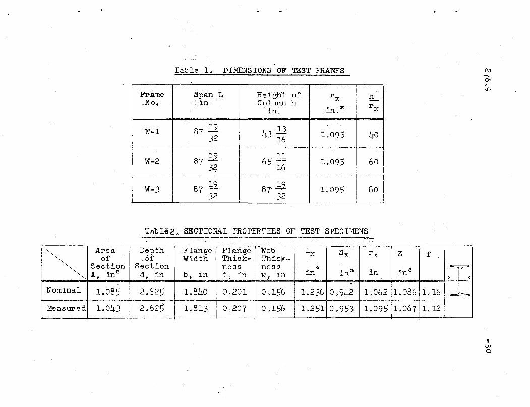
summarized in Table 1 and detailed in Figo 30 Three sets19 .
of frames with span lengths of 87 32 inches and heights of11 11 1943 16 P 65 16 and:87 32 inches·respectively were designated
as W-I,ll W-2 and' w-3 in sequence of their heighto
The following features of the frames distinguish the
present investigatiqn from its predecessorso
(1) Frames were subjected to a primary bending moment
and were loaded into the inelastic rangeo
(2) The most practical structural shape of WF section
was a,doptedo
(3) Members of a frame were subjected, to strong axis
bending,ll therefore,ll two frames with a bracing
system between themw~re tested at the same time
'to eliminate premature lateral-torsional buckling.
(4) The lo'ad vs 0 slenderness ratio of the columns were
chosen as variables in this investigationo

27609 -7
/'
...
•
From the theory of eccentrically loaded columns, it is
known that the effect of eccentricity upon buckling strength
is considerable in the plastic range of buckling but tapers
off in the elastic range with increasing slenderness ratio
of the columns 0 This implies that the slenderness ratio of
the columns of a frame plays an important role in the buck
ling strength of the frame in the inelastic rangeo Therefore,
three sets of frames with different column heights were
testedo The slenderness ratios ,of the columns were chosen
such that inelastic buckling of a frame would occur prior
to the formation of failure mechanism in simple plastic
theoryo The variables governing the buckling strength were
the load P on the column and slenderness ratio ~ of thex
column~ while the span length and cross sectlon of the member
were kept the same for the three frames o
:2 0 2 Sectional Properties
The shape of the cross section of the member is one of
the 'important factors affecting the buckling load o Some
frame stability tests have been conducted using box sections,
tubes or solid bars but so far no test of this kind has been
conducted using WF se.ctiono In practical building frames,. .however, WF sections are commonly usedo Therefore, the
frames were fabricated from 2 t x l~ WF shapes designated

276 0 9 -8
•
•
Noo M-2362 by Bethlehem Steel Companyo The cross sectional
dimensions were measured with the aid of a micrometer and
actual properties of the section were compared with those
given by Bethlehem Steel Companyo A-comparison of the actual
and nominal properties is shown in Table 2 0
203 Material Properties
The material properties of the member were determined
by tension coupontest g stub column test and control beam
testo Two coupons cut from the flanges and one from the web
of the section were tested in a screw type testing machineo
Load and elongation over a 6 ino gage length were measured
and plotted by means of a Tinius~Olsen extensometer and a
low-magnification automatic stress=strain recordero The rate
of application of load was about 0 0 025 inch p~r minute and 0.1
inch per minute after strain hardeningo After the yielding
region had been reached but before strain-hardening had
commenced g the strain rate was reduced to zero for a period
of a few minutes to allow the load to reach an equilibrium
point~ From this reading the lowest possible.yield stress
could be calculatedjl thus insuring that in the actual test
structure the yield stress would be equal to this or greater.
The results of coupon tests are summarized in Table 40
A cross-section (stub-column) test was made to find the
compressive stress-strain curve of a full cross=section of

-9
•
•
the member of the .frameso This was an axial compression test
which gave the integrated effect of different web an~ flange
strengths in one testo The main purpose of the test was to
obtain·a compressive yield value to use in predicting the
theoretical buckling loado It should be pointed out that
there is.a substantial difference of yield stress level be
tween flange and web, as shown in the results of coupon tests
in Table 3. Therefore, the stub column test is necessary and
the result of the test gives' a more reasonable yield stress
level. The specimen was 6 inches in lengtho Two SR-4 strain
gages were provided for the measurements of strains. Prior
to the stress~strain test, the specimen was aligned to insure
concentric loading. The result of the test is shown in Fig. 4.The average yield stress level of flange coupons is very close
to the result obtained from stub column test. Therefore, the
average value of 42~693 ksi was adopted as the y~eld stress
level.
In order to obtain the actual moment-curvature relation
ship of the section as shown in Figo 5, a con~ol'beam test
was necessary. The test setup is shown in Figo 5.· The beam
was simply supported at its ends and loaded at its third points
causing pure bending in the portion between the· concentrated
loads. Two optical mirrors were attached to rods welded per
pendiCUlar to the plane of the beam at:;the .load pointso The
mirrors reflected the image of a "graduates scale 10 feet away

..
from the ·center of the beamo When load was applied, the
beam and the attached mirrors as werl, rotated o Readings
of the reflected image of the scales in each mirror were
obtained through a transito The increments of the scale
readings were used . to calculate the angular rotation be
tween the points of the two mirrorso The unit angular
rotation gave -the curvature of the beam under the applied
moment 0 The moment-curvature curve of the 'section is
plotted in Fig o 60 SR=4 strain gages at~ached at the
flanges also provided additional results for check. The
plastic moment Mp from the test result was 4706 kips-in.
However~ another Mp of 46.87 kips=ino was obtained by cal
culation based on the measured area of the section and the
adopted yield stress level~ Therefore it was decided that
Mp value of 47 kips-ino would be adopted for theoretical
predictions 0
2 0 4 Loading Condition of Test Frames
As shown in Figo 2 a uniform beam loading was approxi
mated by three concentrated loaq.s El0 . A concentrated 10adP
at the top of the column represented the loads .. from the upper
floors. This particular loading condition would simulate a
condition that may be expected in the lower stories of a tall
building. A parameter a which relates the magnitude of th&
concentrated column load P to the beam load PI was kept con
stant for each case o This implied that the beam and column
loads were assumed to increase simultaneously with a fixed
27609 -11
i1
•
;.
..
ratio a between themo The total number of stories was then
a+l~ In this experiment a was about two, therefore, the
frames could be considered as the first story of a three-
s tory bUildingo
205 Design of Test Frames
The frames were designed according to the method of
plastic design outlined in References (2) and (3}0 Since
the loading pattern and the size of the beam had been
selected in advance, maximum moments and forces throughout
the frame could be determined on the basis of a simple
plastic analysis considering a beam mechanismo Knowing
-. these moments and forces, base fittings and welded connec- i
tionswere designed.
The knees, column base plates and loading points on
the beams were of all-welded construction. The frames were
fabricated in the laboratory by welders and fitters who~e
re'gular jobs involve similar operations at the plant of a
steel fabricatoro'
2.6 Lateral Bracing System
Past experience in testing rigid frames into the plastic
range had shown that adequate lateral support was essential
if the theoretical ultimate load was to be attained. This
would prevent lateral-torsional buckling of the member o In
this investigation two frames' connected by a lateral bracing

276e9 -12
•
1
..system were tested at the same time 0 Thus eliminating possi
ble frictional forces to be developed between the model frame
and lateral supporting guide if a single frame would be tested.
The system was composed of welded purlins made from
1 ~n x i" c.hannels and cross braces 0 The cross braces were
1" ¢ 1made of 4 threaded steel bar, 2 2" turn buckles and hooks.
The cross sectional properties of the purlins are given in
Table 30 The spacing of purlihs was less than 45 r y of the
main frame member which was well within the critiG~l length
for lateral torsional buckling in the inelastic range as
suggested in· Reference 16, where r y is the radius of gyration
about the weak axis of the sectiono The lateral bracing
system can be seen in the photographs of the test frame in
Figso 7, 8 and 90

-13
,
e'
..
3 e LOADING SYSTEM AND TEST APPARATUS
301 Requirements and General Arrangement
There are several basic principles upon which the load
ing system and test apparatus were designed o These require
ments~on the other hand~ characterize the peculiarity of the
test setup" Fig,,' 3 shows a general arrangement of test setup
which was designed to meet the following requirementso
(1) Proportional loading should holdo
(2) Loading systems should not restrain the frame from
sidesway movemento
(3) Loadingsystem~ apparatus as well as the frames,
should be symmetrical in both directionso
(4) Nearly perfect pin-ended column support ,was required"
(5) Deformation of the frames at every stage ".of loading
should be measured precise~yo
According to the above mentioned requirements, the load
was applied on the frames by five sets of· lever systems to
gether with dead,weight on loading basketso One end of the
.'mUltiplication lever was connected with the base beams (ground)
by wire ropes and turnbuckles~ while the loading basket was
hung on the other "endo ' The turnbuckles were used to adjust
the lengths of wire rope so that the multiplication lever
could be kept in levelo The lever ratios of multiplication
lever were designed to magnify the dead weight on the loading
basket and also to produce a proportional increment of load

,on the frames o By proportional loading it is meant that the
" ratio of column load to the beam load was constant at the
value and throughout the loading process o The frames to-
gether with loading system were fixed in position by four
sets of column base fixtures on the base beams so that the
frames could sway freely only in the plane of the frames o
The two l4WF3l4 oase beams and one l4WF61 bea~ in between
were anchored to the concrete floor of the test beg by two
bolts of four inches in diametero The base beams were heavy
enough to transmit the load to the floor without any appre
ciable deformationo The weights used for loading were 20
and 50 pound steel blocks and assorted round blocks with
·varying weights of 10 to 55 pounds as shown on the baskets
in FigsolO, 11 and 120 They were provided by Bethlehem
Steel Company0
3 0 2 Beam Loading System
.Section A-A of Figo 3 indicates the type of loading
device which transmits the loading weight on the basket to
the beams of ·the frames 0 There are three identical devices
hung on the middle of the third point of the beamso Since
the systems were connected with the base beam by wire ropes,
initiation of sidesway of the frames would not bepreventedo
At the six loading points on the beams, specially designed
hangers connected the loading syst~m to the frames o At the
point of attachment of the 3I507 multiplication lever to the

-15
•
•
315'.7 spreader beam ,l a screw device was provided to allow
equal distribution of the load to each frame. Any error in
the lever ratio of the multiplication levers could produce
an incorrect load on the beams. This could be corrected by
putting a slightly different weight on 'the l()ading ~asket so
that the six readings from the dynamometers were nearly equal.
The reading from the dynamometers gave direct~y the, magnitude
of the concentrated load ~l on the beamo
303 Column Loading System
, Referring to the elevation of Figo 3 ,l there are two sets
of column loading system ,l one at each end of the frame. Each
column loading system applies a concentrated load to the pair
'of columns at its end of the frame. A multiplication lever
made from a 6 B 12 with welded 1/4 inch cover plates was
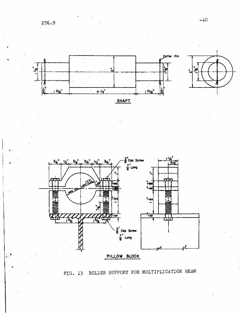
rested on a spreader beam of 6 B 12 sectionoA roller support
between the spreader beam and the multiplication lever en
abled'the frames to sway f~~ely without introducin~ serious
frictional force. As shoWn in Figo 13 a shaft and,two sets
of roller bearings were fitted into a pillow block and a
pillow block was screwed to each spreader beamo A sample
bearing was proof tested under vertical load of 20 kips to
assure adequate rolling capacity of the bearing during the
test. '

\'
-16
..One end of the multiplication lever was ~ied down to
the base beam by a 1/2 inch di~meter wire rope, a dynamometer
and a turnbuckleo The turnbuckle was used to adjust the length
of the wire rope to keep the multiplication lever in level o
Otherwise a horizontal component of force from the loading
beam would tend to push the frame sidewiseo rhe column load
-P was obtained by ~dding the dynamometer reading in the tie
down wire rope to the weight of the loading beams plus the
weight of the loading basket and added weightso
304 Column Base Fixture
Since a slight restraint at the column end tends to in
crease the buckling load considerably as shown in Refo 17, a
perfect pin-ended support free from any restraint was
necessaryo ·Figo 14 shows the details of one of the column
base fixtures usedo The column base plate·was connected to a..shaft which was cut flat at the top sOc.:that the base plate
could fully rest on the shafto F~ur3/l6"'¢ screw wer~used
to fix the column to the shafto ·The shaft was fitted into
two roller bear ings of ·40 ton capacity e,acho .The'"Rearings
were held in, a pillow block which was acrewed.to.~_stiffened
base box" The base box was then clamped to the flange of a
.. base beam" In order to assure that no slip would..o,c cur be-
tween the base box and base beam during test,.spot_welding of
about one inch in length was done after alignment of the
frames was completedo -Then the frames could only sway freely;
in the direction of the plane of the frameo

-17
•
305 Deflection Measurement
The deflections of the beams and columns of the frame
at the end'of each loading increment were measured by a
graduated scale and transit o :The scale was.·about one foot
in lengtho One end of the scale was pointed so that it
could be inserted into punched holes on the frameo The holes
were punched 6 inches apart throughout the outer surface of
the flanges of the frame members 0 The pattern of the holes
is shown in Figo 150
Three transits~ one for each me~ber~ were set up in
front of the frame for deflection measurement. Reference
points were marked on the floor and wall to fix the positions
of the transits and their directions of observationo The
deflection was. read accurately to 0001 inch and .estimated
to the next digit o
As shown in Figsci 10 ~ 11 and 12~ there was a vertical
rod beside each columno Horizontal lines on the rod were
drawn at the same level as the punched holes on the columnso
By holding the scale in the punched holes ;:and along the line,
horizontal deflection of the column was read through a transit
which could only rotate in a vertical plane parallel to the
column 0 In order to measure the vertical deflection on each
beam, a triangular plate was used to assure the vertical
position of the scaleo The transit was fixed against vertical
rotation but it could rotate in a horizontal plane along the
beams for taking vertical deflection of the beamso

. .27609 -18 .
30~ Strain·Measurement
• strain in the frames was measured by attached strain
gages 0 ,All strain gages were electric resistance SR-4 type
A-I linear gagesoThe location of the gages on the frame is
shown in Figo 160 There were 24 gages throughout the frameso
The gage readings were used to align the point of application
of the loado The alignment would not be perfect until the
strain reading showed symmetrical figures in both directions~
A relatively small number of gages was used on the tests,
because the elastic behavior of the frame was not being
emphasized in theinvestigationo After the yield point has
been reached at a gage location, knowledge of the exact
magnitude of strain is not of prime importance, however, all
of. the strain readings were taken after each increment·of
load throughout the testo The strain gages were connected to
a switch box and then to the strain indicatorso. ,

276,,9
5", TEST PROCEDURE
-19
5,,1 Test Setup
After the frames were erected on the base beam, s.train
gages were mounted and wires were connected to the switch
boxes and indicators" Then the frames were whitewashed I,
with hydrated lime" Flaking of the whitewash during testing
indicates the progression of yielding" Initial readings of
strains and dynamometers were taken before the heavy loading
beams and baskets were put on the frame" After the loading
beams were set in position, turnbuckles were~djusted to
keep the loading beams level"
5,,2 Alignm~t of Test Frames
Around 200 pounds of weight was loaded on each loading
basket" By taking increments of the load dynamometer read
ing, it was easy to figure out which side of the frames was
overloaded" .. The weight was unloaded and the lever ratio of
the multiplication lever was adjustedoThe process was re
peated until the difference was within 5%"
After alignment of the multiplication lever was fini~hed,
strain readings were taken" Unsymmetrical strain readings
indicated that the point of application of the loading system
was deviated" Again the weight was removed to adjust the
position of the spreader beam on the columnsd' Alignment was
continued until the increments of reading 'from strain indi
cators and dynamometers gave symmetrical values within 5% error"

27609 -20
It is of interest to point out that for the first and second
sets of load increments~ the readings were not quite satis=
factoryo However~ when the load was increased more~ the
results tended to be more reliableo' An explanation for this
could be that the initial deformation in the wire and multi
plication lever affected the initial reading very mu~ho
503 Testing
Figures 10~ 11 and 12 show the testing of frames W-l,
W-2 and W-3 respectivelyo In order to keep the relationship
of proportional loading~ 80 pounds of weight was. loaded
initially on each of the thre'e baskets of the .. beams 0 This
was an adjustment to the different weight of multiplication
levers~for the columns o From then on, the same weight on
each basket would produce proportional loading on the frames o
Two men were necessary· for reading and rec,or.d-+ng the
dynamometers and strain indicatorso The applied. loads on
the beams were calcula~ed by mu~tip~ying the measured strain
increments by the constants obtained from dynamome:lier;:; cali
brationso In case the loading obtained from the dynamometers-.
was not satisfactory~ it could be adjusted by putting on the
baskets a slightly different weight for the next loadingo
Another couple of men took care of the deflection measure-
ment o . One held the scale, while the other took the.readings
through thetransit o The scale was shifted· from one position
to another, and hence the deflections of the beams and c'olumns
were obtainedo
· -21
After each increment of load g the deflections at the
centers of the beams were measured and plotted on the pre
dicted curveo This load vSo deflection. curve would justify
that both the testing apparatus and the frames were function
ing satisfactorilyo
For frame W=l, the first five sets of load increments
were about 200 pounds in each basketo:The IhcramaDt~··was
gradually decreased to about 10 pounds at the final loading,
Noo 190 After loading Noo 10 visible yielding on the frames
was observed at the inner surface of the right colUmn at the
cornaro This'was the first indication that the frames might
sway to the righto The frames started to sway-visibly at
loading Noo 110 From then on g it took more than 20 minutes
of waiting for the frame to slow do~ the sidesway motiono
Several jacks and wood blocks were put under 1;he_b~skets to
assure that no sudden failure of the frame would occuro At
the final loading the frames swayed slowly and continuously,
therefore, no deflection was taken and the test was finishedo
Frame.W-2 was 22 inches higher than frame W:"lo The
wire ropes on the loading be'ams were made 22 inches longer 0
The load increment was 200 pounds for the first· five sets,
then seven sets,of 100 pound increments followedo Finally
three sets of 30 pound increments concluded the testo

-22
Frame W-3 was about 9 feet in height above the floor so
it vibrated co~siderably after each loading processo At the
end of test the "frames swayed considerably so that the rotation
at the knee caused the spreader beam at the top of the column
to tilt too mucho Eventually the spreader beam overturned and
multiplication beam above slid down on the frame o
-23
. _ . ., . ,. . ' . .' '. ;'\ .1 . <' • r .'"t' • ;'. -". • -: ••• -.' • - • ",- ....' •• ~ -.- ....". , ,
TEST RESULTS ANDT.HEIR ,C.OMPARISON WITHTHEORETICAL PREDICTIONS
5.. 1 Test Results
Generally speaking, the test frames and the apparatus
behaved satisfactorily throughout the testo
The deformed shapes of the frames W=l and W=2 are shown
in Figo 17 and 18 respectivelyo The last set of deflections
was not taken due to overturning of one of the spreader b~ams
a t the top of 'the column,\> .therefore,\> the deformed shape of
frame W=3 is not shown 0
The dotted lines in Figo 17 and 18 show the deflected
shape of the frames when the horizontal deflection of the
column top first became noticeable.. The load corresponding=
to this point is defined as critical load Pcro The solid
lines show the shape of the frames just before the ultimate=
load Pult was reachedo ,Any further increase of the.applied
load would have caused continued sway of the frameso ·Thi~· is
the maximum load the frame can carry and is defined as ultimate
load PUlto
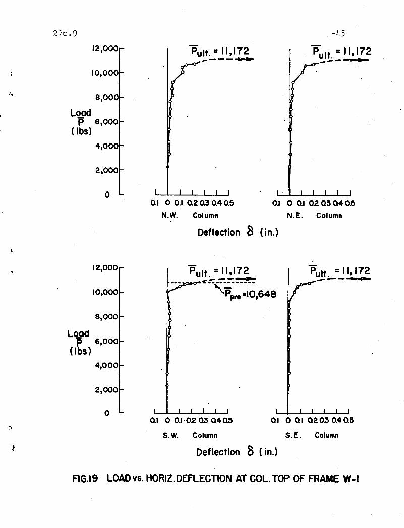
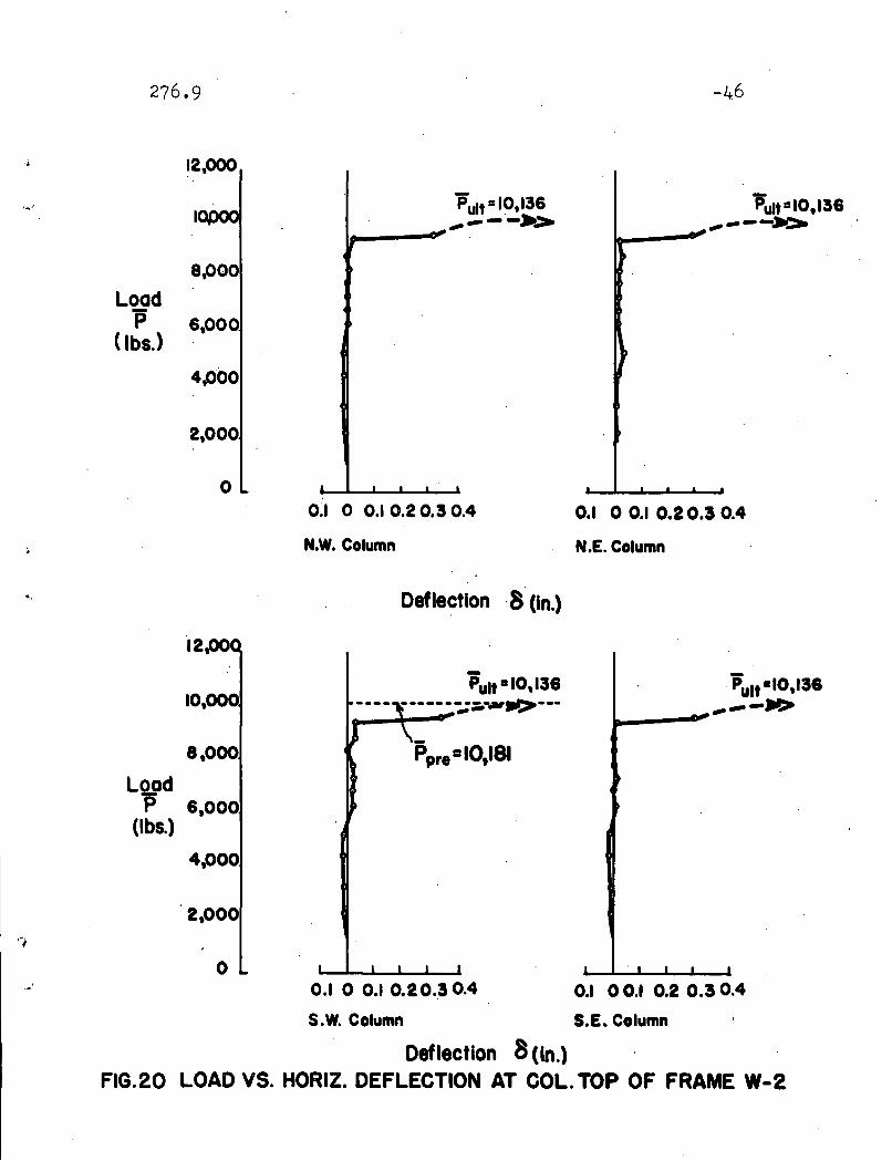
The test results were plotted in Figs 0 ,19.9 20 and 21 as
the load versus horizontal deflection curve at the column top.
,The predicted buckling loads Ppre were shown as dotted lines
on deflection curves of the Southes:!It;- columns of the frames.

-24
,Table 5 provides a summary of all the test results and
of the theoretical analysiso . The ultimate loads obtained
from the tests are 110172~ 100136 and 90160 kips compared
to the predicted buckling loads of Ib0648~ 100181 and 80611
kips for frames W-l~ W=2 and W=3 respectivelyo
Because· of the satisfactory lateral supporting system~
the two frames were acting together as one frame. and no
lateral buckling of the members was observed before the
ultimate loads were reached in any of the three testso
••• - " ._ 0.-'
5 0 2 Comparison of Test Results with Theoretical Frediction=
The ultimate loads Pult obtained from the tests were·
plotted as points W=l~ W=2 and W=3 in Figo ,220 The curves
in the graphs show the predicted inelastic buckling loads
based on the theory given in Hefo 120 For framesW.;.;l and W-3,
the experimental loads are several percent highert~an the
predictedl~ads, while both experimental and predicted: loads
are about equal for frame W=20The average error between the
theoretical prediction and test results is less than 4%0 As
shown in. Figo 22~ a different coefficient of proportionality
.a was used for frame W=3o It was believed from previous test
results that frame W=3 would fail by elastic bucklin~' There
fore, a was reduced to 108 to assure that the frame would
buckle in the inelastic rangeo

=
The experimental buckling load Pult was compared with
the predicted buckling 10adPpre~ beam-column instability= . =
load. Pum and simple'plastic 10adPu as summarized in Table 5.
503 . Comparison with theAISC Formula
To safeguard against frame instability in plastically
designed one= and two=story rigid frames~ the following rule. (18) '.
is recommended in the AISC Plastic nesign Manual o .
"Columns in continuous frames where'sldesway is not
prevented (a) by diagonal bracing (b) by attachment to an
adjacent structure having ample lateral stability or (c) by'-,
floor slabs or roof decks secured horizontally by walls or
bracing systems parallel to the plane of the continuous frames
shall be so proportioned thatP h <
2 F + 70r -100y
where P = the axial force in the column when the-.frame carries its maximum. ..load 0
Py = the axial yield load of the column
h = slenderness ratio of the column ."r
The justifica~ion of this rule can be found in Refo(~
A frame with a combination of axial load and column slender-
ness ratio within the triangular envelope in Figo 23 'can
carry as much load as a braced frameo Test results indicated
that Frame W-l could carry 9609% of the load ofa braced frame.

The point is very close to the lOO~ line, therefore, the
formula is quite accurate in .the vicinity of the loading
and slenderness ratio of frame W-lo
-26

.'
•
2760,9,,-, -27
60 CONCLUSIONS
. The following conclusions can be drawn from the results
of the investigation presented in this papero
(1) T~e predicted buckling loads are very close to the,
experimental buckling loads and are less· than 4% on the safe
side as could be observed in Table 50 This indicates both
the theory and the test are very satisfactory and successfulo
=
(2) The ultimate load Pult is about 84% of the simple
plastic load o The reduction in load carrying capacity from
simple plastic load is too large to be neglectedo Therefore,
a check against frame stability should be made in plastically
designed frame o
(3) The designs of model frames'and test setup are
very satisfactory as evidenced by the test resultso The
success of this test could be considered asa cornerstone
to a more complicated te.st of multi=story frame 0
(4) The agre~ement of the test results with the AISC
formula for the slenderness of columns in frames not, braced
against sidesway provides confidence that the AISC formula
will.safeguard against the frame stability problem inplasti
cally designed frameso Since no tests were conducted in the
regions of h~gher. and lower axial load, a more precise design
formula can not be recommended nowo , However, examination of

-28
..
•
these results in the light of the approximate theoretical',:
analysis given in Refo·) suggests that the AISC formula may
be more conservative in these regionso
The fnelastic buckling problem of single story rectangular
frame has been properly solved and future work should be done
on the stability of multi=story frames o

276.9
ACKNOWLEDGEMENTS
2gB.
..
't
..
This report is based on a thesis prepared, bY' Y.· C. Yen
in. partial fulfillment of the requirements for the Master of
Science degree •
. The work contained in this report is. part of an in
vestigation on "Welded Continuous Frames. and, Their' Components"
being conducted under the direction of Dr. Lynn S. Beedle.
The project is sponsored jointly. by the Welding Research
Council and the Bepartment of the Navy through the Institute
of Research at Lehigh University. ,Funds are furnished by the
. American. Institute of Steel Construction, American Iron and
Steel Institute,. Office of Naval, Research» Bureau of Ships,
and the Bureau of Yards and Dockso The Column·R~search· Council
of the Engineering Foundation,acts in an advisory capacity.
The work was done at Fritz: Engineering Laboratory,. Lehigh
University, Bethlehem, Pennsylvania
The assistance of Mr. Kenneth Ro Harpel"Laboratory
Foreman,.and the' Fritz Lab shop personnel in prep~ring t~e
test setup and in. conducting the tests is greatly appreciated.
The drawings were prepared by Mr. Stanley A., Gawlik and
the manuscript was typed· by: Mrs.· Lillian. Morrow. Their
cooperation is appreciated •

276.9 ' "'1"'29
8. TABLES AND FIGURES
, I
-,
T'ab Ie 1. DIMENSIONS OF TEST FRAMES
Frame Span L Height of' r x h_,No o .: in· - Column h -- r x~in: , in,,:e
-.
W-l 8719
4313
1.095 4032 16,
19 65 11I
W-2 87 1.095 6032 16
. ,_.' ----
W-3 8719 87' 19 1.095 8032 32
_Tab Ie 2 0 SECTIONAL PROPERTIES OF TEST SPECIMENS
"'" Area Depth Flange Flange Web' Ix Sx r x Z f'"-
~of - of Width Thiok= Thi.ok=
S'ection Section ness ness 4in3 in 3
~.~fA in2
d~ in b~ in t p in "IN>, in in in~ :- ., - -- - . - -' --
Nominal 1.085 2.625 1.8,40 0.201 0.156 1.236 0.942 1.062 1.086--_.-
1.121Measured 1 0 043 2.625 1.813 0 0 207 0.156 10251 0.953 1.095 1.067
RWo

Tab Ie 30 SECTIONAL PROPERTIES OF FURLIN..
Area of' Depth of .Flange Flange~ Web I S r x r ySection Section Width Thickness Thickness .x x.
f'A, in2d~ in b· in t~ in w~ in 'in4 in 3 in in~
. --
0 0 34 1.5 0.75 0.188 0.125 0.11 0 0 15 0.56 0.22
Table 4.· SUMMitRY OF COUPON TEST RESULTS
- ~ - .-..
Location (iy QuIt Ey Est E- ,ksi .•·.·~si. . in/in in/tn, ksi
•.
Flange 42~110 54~ 710 0 0 00134 0 0 01336 32,047~000.. .. ..
~,..
n 43,270 54~570 0 0 00125 0 0 01403 31~ 592~OOO,. ... .. .,
Web 48,280 60,350 0 0 00167 0 0 01086 30,483,000
where 6J = Static Yield Level-
GUlt = Ultimate '!Tensile strength
€J = Initial Yield Strain
E~ = Strain at Initiation of Strain Hardening
E = Modulus of' Elasticity
~-E mean = 31,374,000

Tab le .5 0 SUMMARY OF THE TESTS AND COMPARISON WITH. THEORETICAL PREDICTIONS.
.. -. -. -_ .. .-..__... _...-" - - ---
Frame h Experimenta.l- Predicted Cblumn .-- Simple" -- "Per Pult PUlt Pultp ...
urnNo o
r Buekli'ng Loads Buckling Instability 'Plastic>; - - - -,1bs __ 'Load (lbs \ Load ·lbs Load _Ibs '- Ppre 'Ppre Pu Pum Fu= = --
Per '-''P p ,- ~ P r ~ - p r --u1t --
pre um u
_.. ,. .-
W=1 40 9 9~16 , 11 9 172 10 9 648 11 9 533 12 9 433 0 0866 1 0049 00899 00969 0 0928
'- ..W=2 60 8 9 793 10 9 136 10 i 181 11 9 469 12 9 433 00864 0 0996 0 0815 0 0884 00922
fW-3-, ..
80 8 9 194 9 9 160 8 9 611 10 9 437 I 11 9 432 0 0952 1 0064 0 0801 00818 0 0913
I\.UI\)

276.9 -33
•
Load
H' I Case I
Paint of Bifurcation
1------...·~cose2 -n.-- ·I 1 , .-0-........ ' II "... .,, /. ., Case 3
/ .•./
./ 0 Point of instability./
./
Horizontal Deflection of Column Top
FIG.l TYPES OF FRAME INSTABILITY
P
FIG. 2 DIMENSIONS AND LOADING OF FRAMES
PPI PI PI
~ 29 13- 2913a
14JJ:'...."'4 32 64 64 32
L a87!!.-32
- N It)
3 I • •paO( yP,) ~ ~ ~
~ ~ ~0 of... ...P a(l+o) t PI
• a=l!! ~IN!!!I!! -",It) II) ....
oa2 .. CD CD• • •
.""~1 1 1
77r
..

MODEL FRAME
SECTION 0-0
Catler
2 5/8 YF3.725( No. M-2362 of Bethlehem Steel Co.)
o
12' 0"
9' 2",A
50 17 ~2 " =87 19/32'- - 1
14 'IF 314 ase BE am12'-0" Lan -fIi=i===~
I " ~'----- \ / \ / . \ /' 'I~ 0-'S;.6 BI2 with /4 Caver II!. ..L=.L:.. "'l\J h / l<\ I \ lit 't\ii!-:!-If-:A-TI-~+-+_-r'="ll-- 1--,.._,...I
11'.n" _~" ~ 11/ I ~ 81/U~·Yz.~':.if!..~'~-'-;\$::""F~----'==:!===gll;:'-~0~"=;-;::===~~~~~~ -~- '~:I-¥-",? '~H- --f, - .. , - -~- ~
14YF61-II'-4"Lang/ .~/1..-...':::.' IJ \ 'IJ \ I \\ 1 \\ -i-6B/2-3'-2"
\/ \'1 \'
•
5 Y16"x IY16"x ~4' II!. .10~
i61i 11m-:"CXl
~• C\l-to
I 2 V811·I~CD
to
,S
FRITZ ENGINEERING LABORATORY
LEHIGH UNIVERSITY
Drawn by _ _ 'L.."S..:.... If'!::- _;:Ife. .' -HiApproved by 9>~ _
PROJECT NO. 276
TEST FOR FRAME STABILITY
CORNER CONNECTION
/I.
l!'~ ~'~ ,
T 23
5/S'x 15/S" x1/4" II!.
716". - YS" Screw
SECTION S-S
COLUMN BASE CONNECTION
rS
14 'IF 314Base Beam
1'-6"
I
\
\
\
I
/4YF61Base Beam
SECTION A-A
6BI2
n 1'-6"
1-'-I~=-2' 3:....Y4:...."_-t-__--"3!...'.:..--,,,0_"--F--l II" 5"5" II"
O:f5:z:::;t;'J=.=~~:'315.7 Spreader Beam
1/4" ~ Sling ----:I.'i<> 315.7 Magnification Lever
14 'IF 3/4Base Beam
Turnbuckle.I
1/4'. Wire Rope
Loading Basket
Spreader Beam
Dynamometer
C\l.:;:..toI--
Roller Bearing
==-= ---=--=-~--=--==;:,5"0" :
1
ELEVATION
2'-0"
4'IF314 F======== --~-=-=1: I 5' -0"
2'· 1/64"
Model Frame---n",
6BI2 with V4"C.1I!.
Date' Aug. 30, 1961 NO.3-I
FIG. 3 MODEL FRAME AND TEST SET-UP

276.'3 ~35
...so·
40
u.( ksi)
O....._~_---lL....-_...L-_--I__...&.-_......&._--'--~
o 0.002 0.004 0.006 0.008 0.010 0.012 0.014
E (in I in)
FIG. 4 STRESS-STRAIN CURVE FROM STUB-COLUMN: TEST
50
7
L l p
20
40
2 3 4 5 6
• x 10 - 3 (Rod./in.)
FIG. 5 MOMENT-CURVATURE CURVE FROM. CONTROL BEAM TEST
M(kip -in.> 30

•
276.9
------------------------
-36
Fig. 6. SETUP FOR CONTROL BEAM TEST
Fig. 7. FRAME W-l AFTER TESTING

276.9
--------------- ---------
-37
,
Fig. 8 FRAME W-2 AFTER TESTI NG
Fig. 9. FRAME W-3 AFTER TESTI NG

•
276.9
Fig. 10. TESTI NG OF FRAME W-1
Fig. 11 TESTI NG OF FRAME W-2
-38

•
276.9
Fig. 12 TESTI NG OF FRAME W-3
-39
.;.40
•• .§JN _
fter Pin
• •1-- - - N -- - -D
I"" I"
4' 17/16 4 1/4" 17/16b 14
SHAFT·
.. i beop .Screw
7"i'L0n9
.ii Cop SCrew7 b
8 Long
.. .,,~'.:'. PILLOW BLOCK
FIG. 13 ROLLER SUPPORT FOR MULTIPLICATION: BEAM

276.9 -41
Roller Bros. to bePressed Each Endof Shaft Bore of .
r-t--"7'"+-E~---.Bro. 1.250 In. +.0005-.000
3 "V,6 olesd 1i2" I!¥a"
rl an ap I H
1.
!¥ " 1 I" ~16"!.L.
0 I=~ 0s;---$ . ~~ $t- I
IIn' =~;;
1 3/4' 2 "aII
3 "I V4
55/all
SHAFT
7J IIDrill ~6 • Hole
HOle
PI LLOW BLOCK
FIG. 14 COLUMN BASE FIXTURE

276.9
tr~---12 6"----.-1.,
ill~~~~ ~ ~
000--II II IICD CD CD
~
ill
-4'Z
FIG •. 15 . LOCATION QF DEFLECTION~MEASUREMENT
=
. FIG •. 16 . LOCATION· ©F STRAIN GAGES

276.9 .... 43
,IIIIII
-.".,.----- ---- --------
N.W. Column N.E.Column
S.E. Column
LEGEND,II1II
- - 9216 1bS.---- P=Pc,= .
---P=IO,720IbS
.( Immediately before Pult)
DEFLECTION SCALE
S.W. Column9 ~ ~ INCHES
"'
FIG.17 . DEFORMED SHAPES,OF W~l

...
'f
276.9
II,,,
II,I,,,
N.W. Column
II,IIIII,,
S.W. Column
LEGEND:
- - 8193 Ib,.----, P=Pcr •
--- p= 9,610 (before isult)
DEFLECTION SCALE'
9 ~ ~ INCHES
,.;.44
,,IIIIIIII,,
N.E. Column
I,,IIIIII,,,
S.E.Column
. FIG. HL., DEFCDRMElD'SHAPES ©F W-2
276.9
12,000
10,000
8,000
PUlt. = 11,172.,.,.---""'-
-45
Pult. =11,172._--- as __
LoadP 6,000
( Ibs)
4,000
2,000
o0./ 0 0./ 0.2 Q3 0.4 0.5
N.W. Column
0.1 0 0.1· Q2 Q3 Q40.5
N.E. Column
Deflection 8 (in.)
Pult . =II, 172--- .--
S.E. Column
0./ 0 0./ Q2 0.3 Q4 0.5
Deflection 8 (in.)
PUlt .= 11,172..-.--------,=------Ppre =10,648
S.W. Column
0.1 0 0.1 02 Q3 Q4 Q5
.. 12,000
10,000
8,000
LqpdP 6,000
(Ibs)
4,000
2,000
0
'J
~
FIG.l9 LOADvs. HORIZ.DEFLECTION AT COL. TOP OF FRAME W-I
}
.,
.'
12,000
8,000
Loadis 6,000
(Ibs,)
4.000
2,000
°
12,00
10,000
8,000
LoadP 6,000
(lbs.)
4,000
2,000
o
0.1 0 0.1 0.20.30.4
N.W. Column
Deflection ·8 (In.)
PUlt 1110,13&
Ppre=10,181
0.1 0 0.1 0.20.30.4
S.W. Column
-46
0.1 0 0.1 0.20.3 0.4
N.E. Column
.PUlt -10,13&..---»'>.....---
0.1 0 0.1 0.2 0.3 0.4
S.E. Column
Deflection 8 (In.)FIG.20 LOAD VS. HORIZ. DEFLECTION AT COL. TOP OF FRAME W-2

276.912,000
10,000
8,000
Loadp 1,000
(lbs)4,000
2,000
o
PUlt =9,160."".----- -~
0.1 0 0.1 02 03
N.W. Column
-47
PUlt. =~160--- .....,,---
01 0 01020.3
N.E. Column
•
'. 12,000
10,000
8,000
LoadJ5' 6,000
(Ibs)
4,000
2,000
Deflection 8 (in.)
PUIt. = ~160-----~.
::::--f~-- -------'-Ppr• I: 8,611
PUIt. = ~160------~~
"
il
o0.1 0 0.1 0.2 0.3
. S.W. Column
0.1 0 0.1 02 0.3
'S.E. Column·''';
Deflection 8 (in.).
FIG.21 LOAD VS. HORIZ. DEFLECTION AT COL. TOP OF FRAME W-3

276.9 ~48
1.0: - - - ~ - - - - - - - - - - - - - - - - - - - \" Simple Plastic Load
oW-I
.8eam Column InstabRity
#
:-,r
Inelastic.6 Buckling
."p '.'.
P "'" Elastic-lSu ."~~.4 3 ......
p=aI PI .h
1'=(1+CI)f PI
~2 L a=2.0
P
0 20 40 60 80 100 120., .her
1.0 . ----- - - - - - - - - - - - - - - -,- Simple Plastic Load" .
\. Beam Column Instability
.8 ~W-3
Inelastic :\
Buckling• 0
.6,.,
PA
P.'-rElastlcis
~I- rl ~I '. BucklinglSu p=aA PI
,
}"
.4 2 ......P=(lta)f PI
0 0 =1.8
.2 L-,)
is P
o 20 40 60 80 100 120h,.
FIG.22 TEST RESULTS AND THEIR COMR WITH THEOR. PREDICTIONS

.. .....'
.'-0
W-2• 88.4 % W-3
• 81.8 %
00 10 20 30 40 50 60 70 80 90 100
h-rI~
~IG.23 COMPARI'SON. OF TEST'-0
RESULTS WITH THE AISC DESIGN RULE
0.3 A I S C Ru Ie.
2;+=10 t = 1.0Y
0.5 --------------------------------.
0.1
0.4
-p-py 02
-50
.,,:. 8. . REFEREN CES
1.'.~' Beedle, L. S.ON THE APPLICATION' OF PLASTIC DESIGN, ,. Proceedings
· of the Second Symposium on Naval StructuralMechanics, p.538, 1960
2. Beedle,. L. S.· PLASTIC DESIGN· OF STEEL FRAMES,. John Wiley &. Sons,
Inc.,_ New York, 1958
3.WRC-ASCE Joint CommitteeCOMMENTARY. ON· PLASTIC DESIGN IN. STEEL, ASCEManualNo. 41,- (1961)
. Puwein, M. G.D~E KNICKFESTIGKEIT DES RECHTECKRAHMENS, .Die Bau~echnik,
Vol. 18, p.32, (1940)
Masur, E. F., Donnell,- L. H., and Chang, I. C.· STABILITY OF FRAMES IN THE PRESENCE OF 'PRIMARY 'BENDING
MOMENTS, Journal of he Engineering Mechanics Division,ASCE,.Vol. 87, No.EM4, (1961) '.
·4•. Chwalla"E.DIE STABILI TAT LOTRECHT BELASTETER. RECHTECKRAHl\ilEN,Der ~auingenieur, Vol. l~, p.69,· (193~)
Chwalla, .IE. , _and Kollbrunner, C. F..BEITR~GE .2UM KNICKPROBLEM DESBOGENTR~GERS' UND DES
· RAHMENS, Der' Stahlbau,. Vol. 11,. p.94,(1938)
5.
~,
6.(\,
7.
8. Bolton,.A.STRUCTURAL FRAMEWORK". Ph.D. Dissertation,- ManchesterUniversity,. (1957)
9. Salem, A.FRAME INSTABILITY IN THEP'LASTIC' RANGE,- Ph·.D •
. Dlssertation, Manchester University,- (195'8)
,)
-L_i.I :
·10.
. ,, .
Gurney, T. R.FRAME INSTABILITY OF PARTJALLY·.P-LASTIC STRUCTURES,British Welding Research Association, Report 'FE 1/56/68'(1957)' .
,....11 •. Low,.M •. W.
·SOME,MODEL TESTS ONMULTI~STORY' RIGID. STEEL. FRAlVlES,· Proceedings~ Institution of Civil Engineering,
Vol. 13, p.287, (1959)
-51
.,
.'
12 0 LU, Lo WoSTABILITY OF ELASTIC AND PARTIALLY PLA~TIC FRAMES,PhoD.o Dissertation, Lehigh UniversitYII (1960)
130 Winter, Go, 'Hsu, Po .To, Koo, Bo, and Loh ll Mo HoBUCKLING OF TRUSSES AND RIGID FRAMES II Cprnelltrniversity, Engineering Experiment Station BulletinN0 0 36, (1948 ) , . .
140 Ojaliro, MoRESTRAINED COLUMNS, Journal of the.EngineeringMechanics Division)) ASeE)) Volo 86, NooEM5, (1960)
150 LU, Lo Wo and Driscoll, Go Co, JroBUCKLING TESTS ON MODEL FRAMES, Fritz Laborator1Report 27603 Lehigh University, '(in preparation)
160 Lee, Go Co, and Galambos,· To VoTHE· POST-BUCKLING STRENGTH, OF WIDE-FLANGE.BElMS,Fritz Laboratory Report 205 Eo12, Lehigh University,(1961)
170 Galambos, To VoINFLUENCE OF PARTIAL BASE FIXITY ON FRAME STABILITY,Journal of the Structural Division, ASCE, VOlo.86,Noo ST5, (1960)
18 0 AISCPLASTIC DESIGN IN STEEL, AISC, 1959