welder training program - bc trades modules · welder training program ... resources to support the...
TRANSCRIPT

Welder Training Programlevel C
P6: Semi-automatic and automatic Welding i (gmaW i), (FCaW i), (mCaW i), (SaW)Theory Competencies

Acknowledgements & Copyright Permission
The Industry Training Authority of British Columbia would like to acknowledge the Welding Articulation Committee and Open School BC, a division of the Queen’s Printer as well as the following individuals and organizations for their contributions in updating the Welder Training modules:
Welding Articulation Committee (WAC) Members and Consultants—“The Working Group”Jim Carson (Welding Articulation Committee Chair), University of the Fraser Valley (writer and senior reviewer)
Peter Haigh (Welding Curriculum Review Committee Chair), Northwest Community College (writer and senior reviewer)
Sheldon Frank, University of the Fraser Valley (writer and reviewer)
Greg Burkett, Okanagan College (writer and reviewer)
Randy Zimmerman (writer and reviewer)
John H.P. Little (reviewer)
Resource Training Organization (RTO)
BC Council on Admissions and Transfer (BCCAT)
The Queen’s PrinterThe Queen’s Printer, through its Open School BC unit, provided project management and design expertise in updating the Welder Training Level C print materials.
Open School BCSolvig Norman, Senior Project ManagerEleanor Liddy, Director/AdvisorDennis Evans, Production Technician (print layout, graphics & photographs)Christine Ramkeesoon, Graphics Media CoordinatorKeith Learmonth, EditorMargaret Kernaghan, Graphic Artist
Publishing ServicesSherry Brown, Director of Publishing Services
Intellectual Property Program Ilona Ugro, Copyright Officer, Ministry of Citizens’ Services, Province of British Columbia
Copyright Permission
The following suppliers have kindly provided copyright permission for selected product images:
Acklands-Grainger Inc.The Crosby GroupJ. Walter Company Ltd.Lincoln Electric CompanyNDT Systems, Inc.Praxair, Inc.Thermadyne Canada (Victor Equipment)The Miller Electric Mfg. Co.ESAB Welding & Cutting Products
Photo of welder walks the high steel at a construction site, Kenneth V. Pilon, copyright 2010. Used under license from Shutterstock.com
A special thank you to Lou Bonin and Jim Stratford at Camosun College (Welding department) for assisting us with additional photographs. An additional thank you to Richard Smith from England, for allowing us to use photographs of hydrogen bubbles.

ForewordThe Industry Training Authority (ITA) is pleased to release this major update of learning resources to support the delivery of the BC Welder Program. It was made possible by the dedicated efforts of the Welding Articulation Committee of BC (WAC).
The WAC is a working group of welding instructors from institutions across the province and is one of the key stakeholder groups that support and strengthen industry training in BC. It was the driving force behind the update of the welding learning modules supplying the specialized expertise required to incorporate technological, procedural and industry-driven changes. The WAC plays an important role in the province’s post-secondary public institutions as discipline specialists that share information and engage in discussions of curriculum matters, particularly those affecting student mobility.
ITA would also like to acknowledge the Resource Training Organization (RTO) which provides direction for improving industry training in the resource sector and which led consultation on changes related to the BC welder training program.
We are grateful to WAC and RTO for their contributions to the ongoing development of BC Welder Training Program Learning Resources (materials whose ownership and copyright are maintained by the Province of British Columbia through ITA).
Industry Training AuthorityAugust 2010
DisclaimerThe materials in these modules are for use by students and instructional staff and have been compiled from sources believed to be reliable and to represent best current opinions on these subjects. These manuals are intended to serve as a starting point for good practices and may not specify all minimum legal standards. No warranty, guarantee or representation is made by the British Columbia Welding Articulation Committee, the British Columbia Industry Training Authority or the Queen’s Printer of British Columbia as to the accuracy or sufficiency of the information contained in these publications. These manuals are intended to provide basic guidelines for welding trade practices. Do not assume, therefore, that all necessary warnings and safety precautionary measures are contained in this module and that other or additional measures may not be required.

4 WelDer TrAInInG PrOGrAM — level C

WelDer TrAInInG PrOGrAM — level C 5
P6: Semi-Automatic and Automatic Welding I (GMAW I), (FCAW I), (MCAW I), (SAW)Theory Competencies
Table of Contents
Theory Competency P6-1: GMAW, GMAW-P, FCAW, MCAW and SAW processes and their applications 7
P6-1 Learning Task 1: GMAW, GMAW-P, FCAW, MCAW and SAW . . . . . . . . . . . . . 11
P6-1 Learning Task 2: Modes of metal transfer in GMAW, GMAW-P, FCAW and MCAW. . . 27
P6-1 Learning Task 3: Safety requirements for semi-automatic welding processes . . . . . 39
Theory Competency P6-2: GMAW, GMAW-P, FCAW, MCAW and SAW equipment and their operation 47
P6-2 Learning Task 1: Welding power sources for semi-automatic processes . . . . . . . . 51
P6-2 Learning Task 2: Equipment for semi-automatic and automatic filler metal wire-feed systems . . . . . . . . . . . . . . . . . . . . . . . . . . . . . . . . . . 67
P6-2 Learning Task 3: Welding gun assemblies for semi-automatic processes. . . . . . . . 81
P6-2 Learning Task 4: Primary and secondary process variables for semi-automatic welding equipment . . . . . . . . . . . . . . . . . . . . . . . . . . . . . . . . . . . . 91
P6-2 Learning Task 5: Process-related weld discontinuities and their causes . . . . . . . 103
Theory Competency P6-3: Filler metal electrode wires and shielding for GMAW, MCAW, FCAW and SAW 113
P6-3 Learning Task 1: Low carbon steel filler metal electrode wire for GMAW, MCAW, FCAW and SAW . . . . . . . . . . . . . . . . . . . . . . . . . . . . . . . . . 117
P6-3 Learning Task 2: Shielding gases for GMAW and FCAW. . . . . . . . . . . . . . . 137
Answer Key 157


Theory CompeTenCy p6-1:GMAW, GMAW-P, FCAW, MCAW and SAW processes and their applications
p6
-1


WelDer TrAInInG PrOGrAM — level C 9
Module P6 Theory CoMPeTenCy P6-1
OutcomesGas metal arc welding (GMAW) is one of the most widely used welding processes. A high deposition rate, continuous feed mechanism and versatility have all contributed to its widespread use in industrial fabrication, repair and maintenance applications. This Competency describes the basic concepts of the GMAW and FCAW processes and compares them to the SMAW process.
Submerged Arc Welding (SAW) is another widely used welding process. An automated continuous feed mechanism and a high deposition rate make SAW very economical. SAW is therefore widely used in the manufacturing sector, where repetitive welds are required.
Safety is of great concern in GMAW and FCAW, as it is with other welding processes. Electrical shock, toxic fumes and arc flash are some of the potential hazards.
When you have completed the Learning Tasks in this Competency, you should be able to describe the:
• principles of operation of the GMAW, GMAW-Pulsed, FCAW, MCAW and SAW processes
• components of a basic GMAW or FCAW setup
• advantages and disadvantages of the GMAW, GMAW-Pulsed, FCAW, MCAW and SAW processes
• modes of metal transfer
• precautions you must take against electrical shock, toxic fumes and radiant energy from the arc
evaluationWhen you have completed all the Theory Competencies in module P6, you will take a written test. To pass this test, you must score at least 70%. The test will include questions that are based on the following material from Theory Competency P6-1.
• the operation of GMAW, FCAW, MCAW and SAW processes• the components of basic GMAW, FCAW and SAW setups• the modes of metal transfer and their safety precautions
resources
All the required resources for this Theory Competency are contained within this Competency.

10 WelDer TrAInInG PrOGrAM — level C

Notes
Module P6 Theory CoMPeTenCy P6-1
WelDer TrAInInG PrOGrAM — level C 11
P6-1 learning Task 1:GMAW, GMAW-P, FCAW, MCAW and SAWGas metal arc welding (GMAW) was patented in the 1940s. Since then, GMAW and the related FCAW processes have become major processes used in the welding industry. Their single most important advantage over other welding processes is the continuous filler metal wire feed mechanism.
Gas metal arc welding (GMAW)GMAW is extremely versatile and is suitable for welding almost all commercial metal thickness (from light sheet to heavy plate) and structural shapes. The introduction of pulsed gas metal arc welding (GMAW-P), a variation of GMAW, has made the process even more versatile.
GMAW can be used to join many metals: carbon steels, high-strength low-alloy steels, stainless steels, aluminum alloys, magnesium alloys, copper alloys and nickel alloys.
GMAW was originally developed for production welding. Small, low-cost power sources, wire feeders and guns have been developed for use in plants and for maintenance welding. GMAW is used in the auto body repair industry and is popular with hobbyists.
Principles of operationIn the gas metal arc welding process, an electric arc is drawn between a filler metal electrode and the base metal (Figure 1). The heat from the arc melts the end of the electrode wire and an area of the base metal. A flow of shielding gas protects the arc and the molten weld pool from atmospheric contamination.
Welding arc
Shielding gas
Solidi�ed weld deposit
Weld pool Base metal
Contact tip
Shielding gas nozzle
Figure 1—GMAW process

Notes
Module P6 Theory CoMPeTenCy P6-1
12 WelDer TrAInInG PrOGrAM — level C
The main components of the basic GMAW system (Figure 2) are:
• a DC power source to supply the current required to melt the filler metal and base metal
• a welding gun complete with hose and cables to direct the filler metal, electrical current and shielding gas to the work
• a feed mechanism complete with contactor and controls to deliver filler metal wire at the required speed
• a shielding gas system, including hose and flowmeter, to protect the arc and molten metal from atmospheric contamination
• a continuous bare electrode filler metal wire fed through the wire feeder and electrode gun
GMAW normally uses direct current, electrode positive (DCEP).
The wire-feed unit and the power source are normally coupled to provide automatic self-regulation of the arc length. In this setup the power source is a constant voltage machine and the wire-feed unit is the constant speed type.
An alternative combination uses a constant-current power source with a voltage-controlled wire-feed unit.With this combination, changes in arc length cause changes in voltage. This in turn increases or decreases the speed of the wire feed. This results in the correct arc length and a constant voltage being maintained.
Although all GMAW setups have the components shown (Figure 2), there are many variations. In some setups, for example, the power source and the wire feeder are combined in a single unit. In smaller units, a spool of filler metal wire might be included in the welding gun. For high-production setups, however, the wire feeder is often a separate unit from the power source.
+ –
Ground clamp Work leadWire-feed unit
Welding power source
Electrode lead Shielding gas cylinder
Spool of �ller metal wire
Pressure regulator
Flow meter
Welding gun
Figure 2—Basic GMAW setup
Notes
Module P6 Theory CoMPeTenCy P6-1
WelDer TrAInInG PrOGrAM — level C 13
GMAW-Pulsed (GMAW-P) operates differently from GMAW. In GMAW-P, the welding amperage levels rise and fall at an extremely fast, regular rate, called “pulses per second.” In addition, background amperage helps to maintain the arc between current peaks.
The main components of the GMAW-P setup are the same as for GMAW, except that the inverter power source will have added computer software. This software can allow individual setting of pulse peak amperage, background amperage, pulse frequency and pulse width (the amount of time at peak amperage).
To make operation easier, these features are preprogrammed into many units. These are called “adaptive synergic controls.” Instead of having to set many parameters, you only need to adjust one. The internal software adjusts the rest. “Adaptive synergic” means one control with the ability to “adapt” to changing arc conditions.
Advantages and disadvantages of GMAW and GMAW-PGMAW and GMAW-P have many advantages. They tend to be very clean processes. There is virtually no welding slag to remove and weld spatter is minimal. The weld surface is smooth and has a good appearance. These features mean that little post-weld cleaning is needed, which increases savings in this area of production costs.
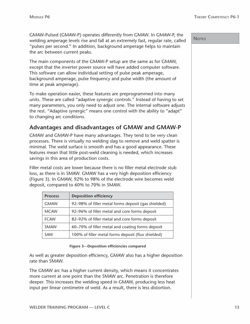
Filler metal costs are lower because there is no filler metal electrode stub loss, as there is in SMAW. GMAW has a very high deposition efficiency (Figure 3). In GMAW, 92% to 98% of the electrode wire becomes weld deposit, compared to 60% to 70% in SMAW.
Process Deposition efficiency
GMAW 92–98% of filler metal forms deposit (gas shielded)
MCAW 92–96% of filler metal and core forms deposit
FCAW 82–92% of filler metal and core forms deposit
SMAW 60–70% of filler metal and coating forms deposit
SAW 100% of filler metal forms deposit (flux shielded)
Figure 3—Deposition efficiencies compared
As well as greater deposition efficiency, GMAW also has a higher deposition rate than SMAW.
The GMAW arc has a higher current density, which means it concentrates more current at one point than the SMAW arc. Penetration is therefore deeper. This increases the welding speed in GMAW, producing less heat input per linear centimetre of weld. As a result, there is less distortion.

Notes
Module P6 Theory CoMPeTenCy P6-1
14 WelDer TrAInInG PrOGrAM — level C
GMAW can be used to weld virtually all metals, except those that cannot be drawn into wire. Cast iron, for example, cannot be formed into wire because it has such low malleability. If you use GMAW to join cast iron, you must use a filler metal other than cast iron.
The main disadvantage to welding with GMAW or GMAW-P is that the equipment costs more than a basic SMAW setup. SMAW also offers a much wider selection of filler metal grades and properties. SMAW is more portable. The Welder can weld anywhere he or she can climb or crawl. With GMAW, the Welder is always “tied” to the wire feeder. Usually, the farthest from the feeder a GMAW Welder can travel is 6 m (20 ft.). Extended-reach feeders can increase this distance to 30 m (100 ft.) with steel wire and to 15 m (50 ft.) with softer aluminum wire.
Although the continuous wire-feed feature is the main advantage of GMAW and GMAW-P, the equipment itself can present problems. The wire can jam, liners can wear out and guides can become misaligned. It takes time and care to correctly set up and maintain these units to ensure smooth operation. The gun nozzle and shielding gas cup need maintenance and frequent cleaning to keep them free from spatter buildup, especially if you are using CO2 as the shielding gas. Note: GMAW-P operates more efficiently using a 80% or higher argon gas mix.
Another disadvantage is that in drafty areas or outdoors, a slight breeze could blow the shielding gas away from the weld area. The result can be contamination and porosity in the weld deposit.
Flux-cored arc welding (FCAW)FCAW is a GMAW process that uses a tubular electrode wire with powdered flux inside (Figure 4). This process is especially well suited to welding low-carbon structural steels and low-alloy and stainless steels. It is also widely used for hardfacing applications.

Notes
Module P6 Theory CoMPeTenCy P6-1
WelDer TrAInInG PrOGrAM — level C 15
Solidified slag
Molten slag
Weld metal
Molten metal
Arc
Contact tip
Nozzle
Flux-cored electrode
Shielding gas envelope
Figure 4—FCAW process
The flux in the centre of the electrode contains elements similar to the coating on an SMAW electrode. These elements act as deoxidizers, slag formers and arc stabilizers. In some cases they can enhance the properties of the weld metal.
There are two variations of the FCAW process:
• Self-shielded: the flux contained in the electrode wire provides effective shielding of the arc and weld pool.
• Gas-shielded: an externally applied shielding gas, as in the basic GMAW process, along with the flux contained in the electrode wire protects the arc and weld pool.
The type of electrode wire you choose determines whether the process is self-shielded or gas-shielded. The core of self-shielded wire contains the ingredients for fluxing and deoxidizing molten metal and for generating shielding gases and slag coverings. Gas-shielded wire contains ingredients for fluxing, deoxidizing and scavenging, with alloys sometimes included to strengthen or condition the base metal. The shielding gas is usually carbon dioxide or carbon dioxide mixed with another gas.
Advantages and disadvantages of FCAWThe main advantages of FCAW (other than continuous feeding, which it shares with GMAW) are deeper penetration, higher deposition rates and high deposition efficiency. The deeper penetration means that heavier stock can be welded in fewer passes. Deep penetration also reduces the need for edge preparation with FCAW. On larger thicknesses that require bevelling, the bevel and included angles are reduced compared to those prepared for SMAW. Narrow openings mean that you need less filler weld metal to fill the joint, saving both filler metal and welding time.

Notes
Module P6 Theory CoMPeTenCy P6-1
16 WelDer TrAInInG PrOGrAM — level C
Because FCAW is able to use high currents, its deposition rate is much higher than with SMAW and conventional GMAW. The deposition rate can reach 12 kg/hr (25 lb./hr), depending on the welding position and the filler metal wire. The average deposition rate for SMAW is 6 kg/hr (12 lb./hr). The deposition efficiency of FCAW is not as high as with GMAW, but it is much higher than with SMAW.
Other advantages of FCAW include flexibility, high-quality welds, excellent control of the weld pool and less stringent pre-cleaning requirements:
• An example of this flexibility is the range of metal thickness that can be welded with one size of electrode by increasing or decreasing amperage and voltage settings.
•High weld quality is due to the protection provided by the shielding gas and the deoxidizing action of the molten slag. The weld deposit is low in hydrogen, and the addition of scavengers in some filler metal wire removes sulphur from the weld deposit, which improves crack resistance. Most welding code work specifies the use of gas-shielded wires.
• The weld pool is more easily controlled with FCAW than with GMAW. The surface of the weld deposit tends to be smooth and uniform in appearance, even with less skilled operators. Because the travel speed is faster than in most other processes, distortion of the weldment can be less of a problem.
• The cleaning action provided by the deoxidizers and other fluxing agents in some of the filler metals reduces the amount of pre-cleaning required on the weld surface.
The main disadvantage of FCAW is its limited application. It can be used only on ferrous metals, including low- and medium-carbon steels, some low-alloy steels and a limited number of stainless steels. This is because filler metals have only been developed for these materials.
Another disadvantage is the initial cost of the equipment. The equipment and electrodes are more expensive than those for SMAW, but faster welding speeds mean that this expense can be recovered. When compared to GMAW, post-weld cleanup to remove the slag is an additional expensive.
Metal-cored arc welding (MCAW)Like FCAW, metal-cored arc welding (MCAW) is a continuous wire-feed process that uses a tubular filler metal wire. The difference is that the metal-cored wire has no fluxing ingredients inside. Instead, the wire is filled with powdered metal. Usually, the powdered metal is iron powder with alloying elements. MCAW wires are designed to run best using argon-rich shielding gases.

Notes
Module P6 Theory CoMPeTenCy P6-1
WelDer TrAInInG PrOGrAM — level C 17
Advantages and disadvantages of MCAWThe main advantages of MCAW are:
• low smoke and fume levels• high deposition efficiency• a broad range of alloy choices• no slag• minimal spatter• good penetration• good bead appearance
As with FCAW filler metal, the manufacturer can easily customize MCAW filler metal by changing the ingredients of the core material.
Because MCAW has no flux, the fume levels are lower than for FCAW. Having no flux and little spatter also contributes to a high deposition efficiency of 92% to 96%.
By adding small percentages of other metals such as molybdenum, manganese, chromium, and so on to the metal powder inside the tubular wire, welding filler metals have been designed to achieve a wide range of metallurgical characteristics. The addition of deoxidizers such as silicon helps reduce the chance of porosity and improves weld pool fluidity.
Spray transfer is recommended for MCAW,.therefore weld spatter is minimal. There is more weld spatter when using short-circuit or globular transfer.
One of the main advantages of MCAW is excellent penetration with a good depth-to-width ratio. Lack of fusion or cold lap is rare.
Compared to MCAW, GMAW is a better choice for welding thinner material such as gauge metal and thin wall structural shapes and FCAW is a better choice if the base metal is very rusty or dirty.
Submerged arc welding (SAW)Submerged arc welding is widely used in the manufacturing industry, and has been since before gas-shielded welding processes became common.
Principles of operationIn the SAW process, a granular flux is deposited on an unwelded seam ahead of a continuously fed consumable filler metal wire. An arc is struck beneath the flux. The molten flux is highly conductive and forms a path for the current to cross the arc. The molten flux solidifies to become slag. After the welding operation is completed, the flux that has not melted to become slag is collected for reuse then the slag is chipped from the weld deposit.
Advantages and disadvantages of SAWThe greatest advantage of SAW is that the process is economical. Very large volumes of weld metal can be deposited in short periods of time. Large-
Notes
Module P6 Theory CoMPeTenCy P6-1
18 WelDer TrAInInG PrOGrAM — level C
diameter welding wire, sometimes 6.4 mm (1⁄4 in.) or more, and currents of 1500 amps or more make this possible.
Another advantage of SAW is that because the arc is underneath the granular flux, there is no ultraviolet light, smoke, sparks or spatter to worry about. There is less need for protective screens, additional ventilation and welding helmets.
The main disadvantage of SAW is that you cannot see the weld as it is being deposited. Therefore, you must be careful that the weld is deposited where required. Also, since the welding amperages are so high, the weld pool is large and fluid. This means that SAW can only be used in a flat or horizontal welding position.
Quality of end productSAW is capable of producing welds of very high quality. For this reason, it is used extensively where long, large welds are often required, such as in the manufacture of ships, large structures, boilers, pressure vessels and tanks.
With the high amperages used in SAW very deep weld penetration is possible. This leads to substantial savings in weld joint edge preparation.
With SAW, careful fit-up and joint preparation are essential to ensure quality welds. To ensure proper joint alignment positioners and manipulators are used extensively.
Operating parameters for Submerged Arc Welding (SAW)
Welding current and polarityA direct current (DC) constant voltage (constant potential) power source is recommended for most single wire electrode SAW. Constant current power sources providing direct (DC) or alternating (AC) welding current are also used for SAW. Constant current power sources are normally used when constant voltage equipment is not available or if alternating (AC) current is required. AC is used in applications requiring multiple filler metal wire electrodes or if arc blow is a problem. As with all wire feed operations, constant voltage welding power sources require a constant speed wire feeder and constant current welding power sources require a variable speed wire feeder.
Direct current electrode positive (DCEP) is recommended for most SAW where deep penetration is important. Direct current electrode negative (DCEN) gives shallower penetration and a higher burn-off rate for the filler metal wire. Alternating current (AC) is occasionally used if arc blow is severe.
When using tandem filler metal wire electrodes, the leading electrode is direct current and the trailing electrode is alternating current.
Notes
Module P6 Theory CoMPeTenCy P6-1
WelDer TrAInInG PrOGrAM — level C 19
Wire feed speedIncreasing or decreasing wire-feed speed directly affects the current required to burn off the filler metal wire electrode at a rate that will maintain the desired arc length. Remember, welding current is the most influential variable for change in penetration, deposition rate and weld bead size. It is the first primary variable you should consider when you need to make changes to these parameters.
Filler metal wire electrode extensionThe distance between the contact tip and the end of the filler metal wire electrode is called electrode extension or “stickout.”
The longer the electrode extension, the greater the heat buildup within the filler metal wire. This is due to the increased electrical resistance of the filler metal wire electrode.
You should use a longer electrode extension when you need a higher burn-off rate for the filler metal wire without having to make adjustments to the welding current. Longer electrode extension also has the effect of reducing penetration. This means that poor fit-up may be welded by increasing the electrode extension, basically reducing the welding current, thus the penetration, and helps to avoid melt thru. After welding of the poor fit-up area, normal electrode extension would be re-established.
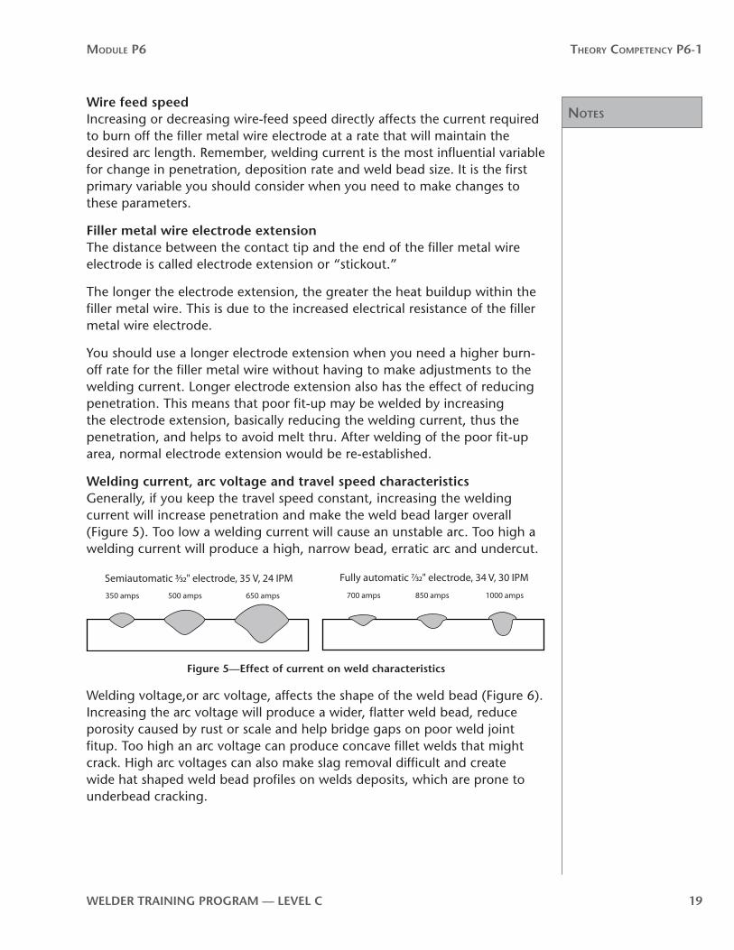
Welding current, arc voltage and travel speed characteristicsGenerally, if you keep the travel speed constant, increasing the welding current will increase penetration and make the weld bead larger overall (Figure 5). Too low a welding current will cause an unstable arc. Too high a welding current will produce a high, narrow bead, erratic arc and undercut.
Semiautomatic 3⁄32" electrode, 35 V, 24 IPM Fully automatic 7⁄32" electrode, 34 V, 30 IPM
350 amps 500 amps 650 amps 700 amps 1000 amps850 amps
Figure 5—effect of current on weld characteristics
Welding voltage,or arc voltage, affects the shape of the weld bead (Figure 6). Increasing the arc voltage will produce a wider, flatter weld bead, reduce porosity caused by rust or scale and help bridge gaps on poor weld joint fitup. Too high an arc voltage can produce concave fillet welds that might crack. High arc voltages can also make slag removal difficult and create wide hat shaped weld bead profiles on welds deposits, which are prone to underbead cracking.

Notes
Module P6 Theory CoMPeTenCy P6-1
20 WelDer TrAInInG PrOGrAM — level C
Semiautomatic 3⁄32" electrode, 500 amps, 24 IPM Fully automatic 7⁄32" electrode, 850 amps, 30 IPM
25 V 35 V 45 V 27 V 34 V 45 V
Figure 6—effect of voltage on weld characteristics
When establishing adjustable variables, follow the manufacturer’s arc voltage and welding amperage recommendations. A good practice is to run a practice weld and check the weld profile. If the weld profile needs to be adjusted, make small changes to either arc voltage, welding current and travel speed (Figure 7) and try another practice weld.
Semiautomatic 3⁄32" electrode, 500 amps, 35 V Fully automatic 7⁄32" electrode, 850 amps, 34 V
12 IPM 24 IPM 48 IPM60 IPM30 IPM15 IPM
Figure 7—effects of travel on weld characteristics
SAW equipment setup
Welding lead cable sizesSubmerged arc welding can be done on materials as thin as gauge metal and as thick as the heaviest plate. The welding amperage used could range from less than 100 A to more than 1500 A. Work lead and electrode lead cables must be large enough to carry the highest welding currents you expect to be using. Use two 4/0 lead cables for less than 1200 A and three 4/0 lead cables for up to 1500 A. Double or triple lead cables help to ensure that there is no power loss due to resistance caused by the lead cables heating up.
Follow equipment manufacturer’s recommendationsSAW equipment, like all welding equipment, is constantly being upgraded by manufacturers. To get the most from your SAW setup, always read the equipment manufacturer’s operator manual.
Setup proceduresThe setup procedures for SAW equipment varies depending on the brand of equipment you are using. Always refer to the equipment manufacturer’s operator manual.
• You must make sure that the filler metal electrode wire straightener is set correctly to remove any curves left after the electrode wire leaves the spool. If the wire is not straightened properly, it can cause the welding arc to wander under the flux. The result will be misaligned weld beads and possible weld defects.

Notes
Module P6 Theory CoMPeTenCy P6-1
WelDer TrAInInG PrOGrAM — level C 21
• The wire feed drive rolls must be the correct type and size for the filler metal wire being fed. They must be adjusted properly.
• Check the contact tip for wear and defects. Replace if required.
• Make sure that the welding flux hopper is full and that the flux is flowing freely.
• Clip the end of the welding wire electrode on an angle. This allows the wire to penetrate through the flux without any hang-ups and helps make sure that the arc starts successfully. Set the electrode extension to the recommended length.
• Set the wire feed speed, arc voltage and travel speed for the type and diameter of filler metal electrode wire you are using. Refer to the setting charts in the equipment manufacturer’s operator manual to guide your setup.
• Check all cable connections to ensure that they are tight and are making good electrical contact.
• Make sure that the polarity is correct.
Now complete Self-Test 1 and check your answers.

Answers
Module P6 Theory CoMPeTenCy P6-1
22 WelDer TrAInInG PrOGrAM — level C
Self-Test 1Choose the best answer for each of the following questions.
1. The main advantage of the GMAW and FCAW processes is the
a. wide range of filler metals available
b. low initial and operating costs
c. minimal training required for operators
d. high deposition rates
2. Match the components of the GMAW setup shown in Figure 8 with the terms listed below.
a. welding power source
b. spool of filler metal wire
c. shielding gas cylinder
d. welding gun
e. wire-feed unit
f. shielding gas flowmeter
g. shielding gas cylinder pressure regulator
h. electrode lead
i. work lead
+ –
G
D
F
A
C
J
K
IH
BE
Figure 8—GMAW setup

Answers
Module P6 Theory CoMPeTenCy P6-1
WelDer TrAInInG PrOGrAM — level C 23
3. In GMAW, the weld pool is protected from atmospheric contamination by
a. a shielding gas
b. the light flux in the electrode wire
c. the copper coating on the electrode wire
d. the high current density
4. Which type of welding power is most commonly used in the GMAW, GMAW-P, FCAW and MCAW processes on steel?
a. transformer
b. constant current
c. constant voltage
d. transformer/rectifier
5. One main advantage of the FCAW process over the GMAW process is
a. absence of slag
b. fast deposition rate
c. excellent penetration on non-ferrous metals
d. the wide range of filler wires available
6. Because GMAW has a faster welding speed than SMAW, there is less heat buildup in the weld area. The result is
a. less risk of porosity
b. less distortion
c. less spatter
d. higher deposition efficiency
7. Another advantage of the GMAW process is the
a. absence of slag
b. ability to weld non-ferrous metals without gas shielding
c. virtual absence of cold lapping
d. greater variety of power source types that can be used
8. Which of the following processes has the highest deposition efficiency?
a. FCAW
b. GMAW
c. SAW
d. SMAW

Answers
Module P6 Theory CoMPeTenCy P6-1
24 WelDer TrAInInG PrOGrAM — level C
9. The GMAW process uses
a. self-shielded continuous-feed filler metal wire
b. gas-shielded manual-feed filler metal wire
c. gas-shielded continuous-feed filler metal wire
d. gas-shielded continuous-feed coated filler metal wire
10. What are the two variations of the FCAW process?
a. self-shielded and gas-shielded
b. short-circuit and pulsed spray transfer
c. globular shielded and submerged arc
d. buried arc and spray transfer
11. Which polarity is most commonly used with GMAW?
a. ACEN
b. DCEN
c. DCEP
d. ACEP
12. The FCAW process is particularly well suited to welding
a. low-carbon steels
b. non-ferrous metals
c. reactive metals
d. high-carbon steels
13. Metal-cored filler metal wire is
a. self-shielded
b. dual-shielded
c. gas-shielded
d. flux core-shielded
14. The addition of silicon to MCAW filler metal wires helps to reduce the possibility of
a. lack of fusion
b. porosity
c. undercutting
d. slag inclusion

Answers
Module P6 Theory CoMPeTenCy P6-1
WelDer TrAInInG PrOGrAM — level C 25
15. The main advantage of SAW is that it
a. can be used for welding in all positions
b. can be used in the field
c. is an economical process
d. does not produce any slag
16. The recommended welding current for SAW is
a. CV/DCEN
b. CV/DCEP
c. CC/DCEN
d. CC/AC
17. Which welding current is used for SAW when arc blow is a problem?
a. CV/DCEN
b. CV/DCEP
c. CC/DCEN
d. CC/AC
18. When using tandem filler metal wire electrodes, the welding current used with the trailing electrode is
a. CV/DCEN
b. CV/DCEP
c. CC/DCEN
d. CC/AC
19. How can you use a long electrode extension to your advantage?
a. to control your burn-off rate without making adjustments to your welding current settings
b. so that the filler metal electrode wire extends past the shielding nozzle and you can reach into tighter locations
c. so you can achieve a lower flatter weld bead profile
d. to raise your welding current without making adjustments at the welding power source
now go to the Answer Key and check your answers

Notes
Module P6 Theory CoMPeTenCy P6-1
26 WelDer TrAInInG PrOGrAM — level C
Notes
Module P6 Theory CoMPeTenCy P6-1
WelDer TrAInInG PrOGrAM — level C 27
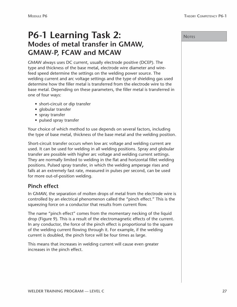
P6-1 learning Task 2:Modes of metal transfer in GMAW, GMAW-P, FCAW and MCAWGMAW always uses DC current, usually electrode positive (DCEP). The type and thickness of the base metal, electrode wire diameter and wire-feed speed determine the settings on the welding power source. The welding current and arc voltage settings and the type of shielding gas used determine how the filler metal is transferred from the electrode wire to the base metal. Depending on these parameters, the filler metal is transferred in one of four ways:
• short-circuit or dip transfer• globular transfer• spray transfer• pulsed spray transfer
Your choice of which method to use depends on several factors, including the type of base metal, thickness of the base metal and the welding position.
Short-circuit transfer occurs when low arc voltage and welding current are used. It can be used for welding in all welding positions. Spray and globular transfer are possible with higher arc voltage and welding current settings. They are normally limited to welding in the flat and horizontal fillet welding positions. Pulsed spray transfer, in which the welding amperage rises and falls at an extremely fast rate, measured in pulses per second, can be used for more out-of-position welding.
Pinch effectIn GMAW, the separation of molten drops of metal from the electrode wire is controlled by an electrical phenomenon called the “pinch effect.” This is the squeezing force on a conductor that results from current flow.
The name “pinch effect” comes from the momentary necking of the liquid drop (Figure 9). This is a result of the electromagnetic effects of the current. In any conductor, the force of the pinch effect is proportional to the square of the welding current flowing through it. For example, if the welding current is doubled, the pinch force will be four times as large.
This means that increases in welding current will cause even greater increases in the pinch effect.

Notes
Module P6 Theory CoMPeTenCy P6-1
28 WelDer TrAInInG PrOGrAM — level C
Current
Electrode wire
Pinch e�ectPinch force = I2
Figure 9—Pinch effect
Short-circuit metal transferIn the short-circuiting, low-energy mode, all metal transfer occurs when the electrode is in contact with the molten pool on the workpiece (Figure 10). This mode involves a short-circuit condition when the wire touches the base metal. At this point the arc is extinguished, there is a sharp rise in current and the molten droplet is pinched off. The surface tension of the weld pool actually pulls the molten droplet from the end of the electrode wire. Once the molten wire is pinched off, the arc re-initiates.
ContactResistance and heat rises
Short circuit as contact is made
Short circuit causes high current
Heat melts o� tip of wire (pinch e�ect)
Deposited weld metal
Figure 10—Short-circuit metal transfer
The filler metal wire continues to be fed through the welding gun to the weld pool. As the filler metal wire makes contact, the arc short circuits and the process repeats. There is therefore an ongoing cycle of short-circuit transfer in which the relationship of arc voltage and welding current changes (Figure 11).

Notes
Module P6 Theory CoMPeTenCy P6-1
WelDer TrAInInG PrOGrAM — level C 29
Wel
ding
cur
rent
Time Short circuit Arcing period0
Arc
vol
tage
Re-in
itiat
es
Extin
ctio
n
Time0
Re-in
itiat
es
Figure 11—Short-circuit transfer cycle
The important feature of short-circuit metal transfer is that filler metal is transferred only when it makes physical contact with the weld pool. No metal is transferred across the arc.
The actual number of transfers varies from 20 to 200 per second. The arc appears to be continuous, even though it is repeatedly short circuiting and re-initiates.
Short-circuit metal transfer is used most for GMAW on ferrous metals. With this mode, you can weld in all positions.
Modified short-circuit metal transferOther short-circuiting metal transfer modes are being developed. These take advantage of the very fast response times provided by microprocessors built into the welding power source. The welding amperage is actually adjusted several times within each short-circuit cycle. These adjustments are very precise and are achieved in different ways by different manufacturers. These variations are patented and go by different names (e.g., Lincoln Electric’s STT [Surface Tension Transfer] and Miller Electric’s RMD [Regulated Metal Deposit]).
This ability to fine tune the heat input makes the weld pool calmer, which reduces lack of fusion problems on root passes. A calmer pool means less spatter. Modified short-circuit metal transfer is more tolerant of variations in tip-to-work distance and uneven weld joint root fit-up.
Notes
Module P6 Theory CoMPeTenCy P6-1
30 WelDer TrAInInG PrOGrAM — level C
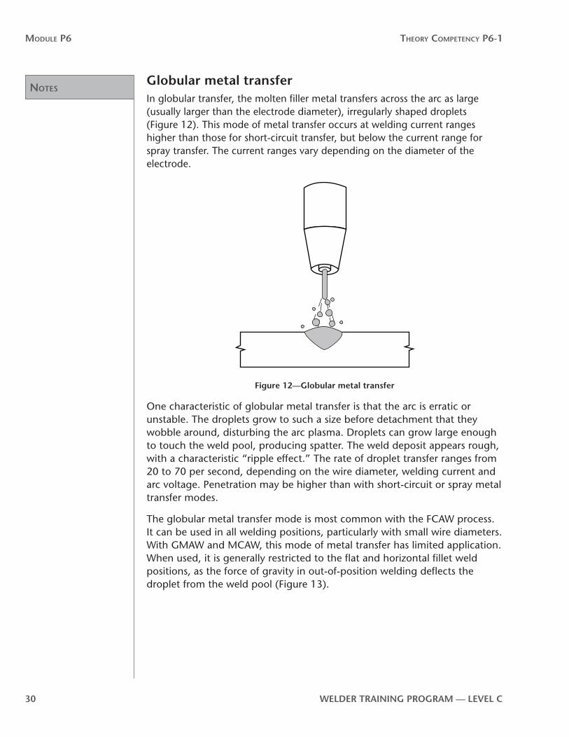
Globular metal transferIn globular transfer, the molten filler metal transfers across the arc as large (usually larger than the electrode diameter), irregularly shaped droplets (Figure 12). This mode of metal transfer occurs at welding current ranges higher than those for short-circuit transfer, but below the current range for spray transfer. The current ranges vary depending on the diameter of the electrode.
Figure 12—Globular metal transfer
One characteristic of globular metal transfer is that the arc is erratic or unstable. The droplets grow to such a size before detachment that they wobble around, disturbing the arc plasma. Droplets can grow large enough to touch the weld pool, producing spatter. The weld deposit appears rough, with a characteristic “ripple effect.” The rate of droplet transfer ranges from 20 to 70 per second, depending on the wire diameter, welding current and arc voltage. Penetration may be higher than with short-circuit or spray metal transfer modes.
The globular metal transfer mode is most common with the FCAW process. It can be used in all welding positions, particularly with small wire diameters. With GMAW and MCAW, this mode of metal transfer has limited application. When used, it is generally restricted to the flat and horizontal fillet weld positions, as the force of gravity in out-of-position welding deflects the droplet from the weld pool (Figure 13).
Notes
Module P6 Theory CoMPeTenCy P6-1
WelDer TrAInInG PrOGrAM — level C 31
Globule
ElectrodeArc
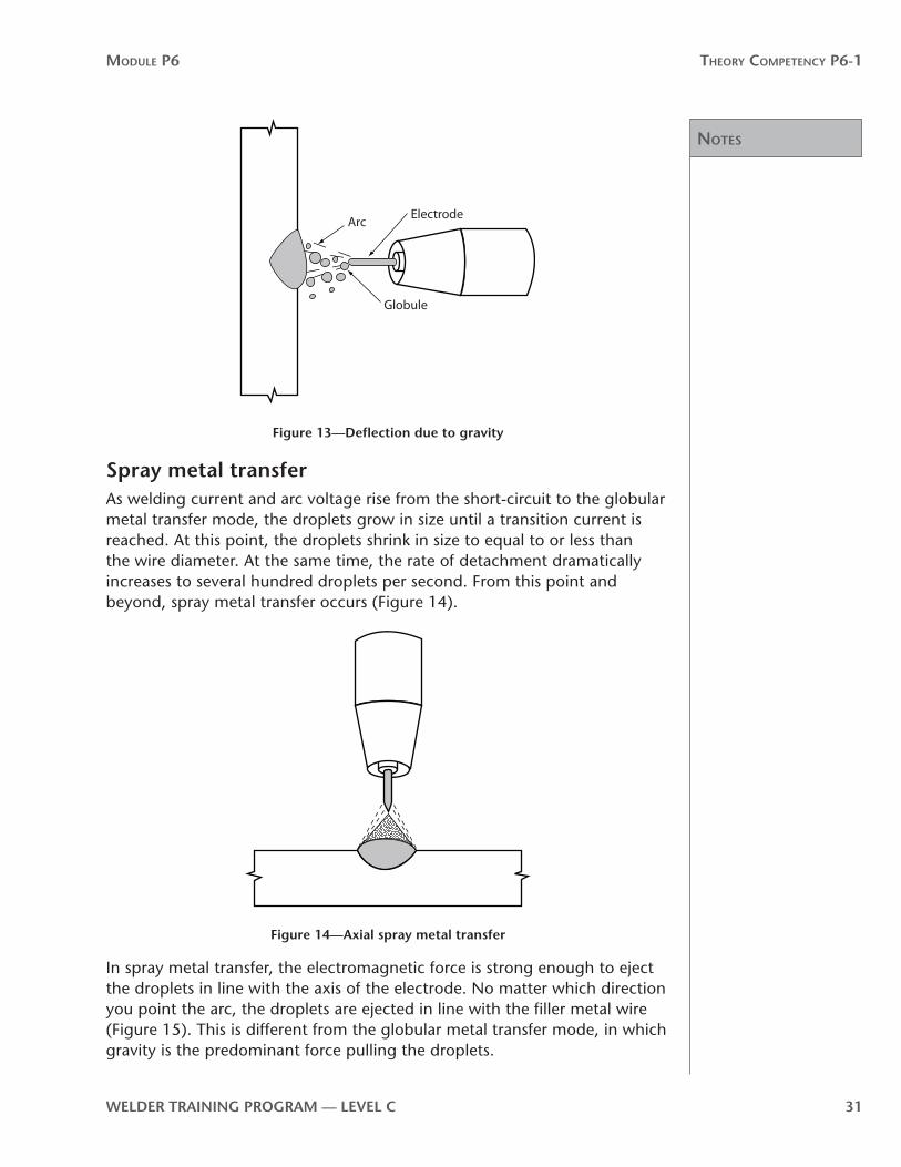
Figure 13—Deflection due to gravity
Spray metal transferAs welding current and arc voltage rise from the short-circuit to the globular metal transfer mode, the droplets grow in size until a transition current is reached. At this point, the droplets shrink in size to equal to or less than the wire diameter. At the same time, the rate of detachment dramatically increases to several hundred droplets per second. From this point and beyond, spray metal transfer occurs (Figure 14).
Figure 14—Axial spray metal transfer
In spray metal transfer, the electromagnetic force is strong enough to eject the droplets in line with the axis of the electrode. No matter which direction you point the arc, the droplets are ejected in line with the filler metal wire (Figure 15). This is different from the globular metal transfer mode, in which gravity is the predominant force pulling the droplets.
Notes
Module P6 Theory CoMPeTenCy P6-1
32 WelDer TrAInInG PrOGrAM — level C
Weld
Spray
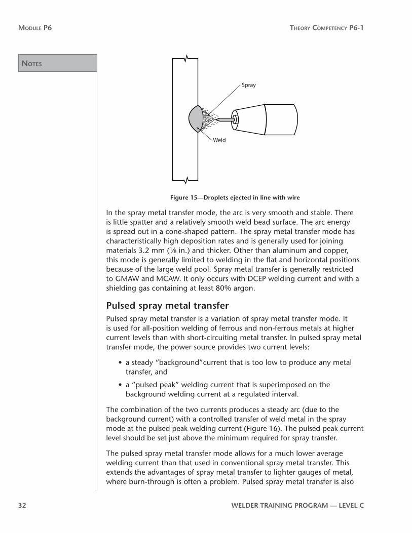
Figure 15—Droplets ejected in line with wire
In the spray metal transfer mode, the arc is very smooth and stable. There is little spatter and a relatively smooth weld bead surface. The arc energy is spread out in a cone-shaped pattern. The spray metal transfer mode has characteristically high deposition rates and is generally used for joining materials 3.2 mm (1⁄8 in.) and thicker. Other than aluminum and copper, this mode is generally limited to welding in the flat and horizontal positions because of the large weld pool. Spray metal transfer is generally restricted to GMAW and MCAW. It only occurs with DCEP welding current and with a shielding gas containing at least 80% argon.
Pulsed spray metal transferPulsed spray metal transfer is a variation of spray metal transfer mode. It is used for all-position welding of ferrous and non-ferrous metals at higher current levels than with short-circuiting metal transfer. In pulsed spray metal transfer mode, the power source provides two current levels:
• a steady “background”current that is too low to produce any metal transfer, and
• a “pulsed peak” welding current that is superimposed on the background welding current at a regulated interval.
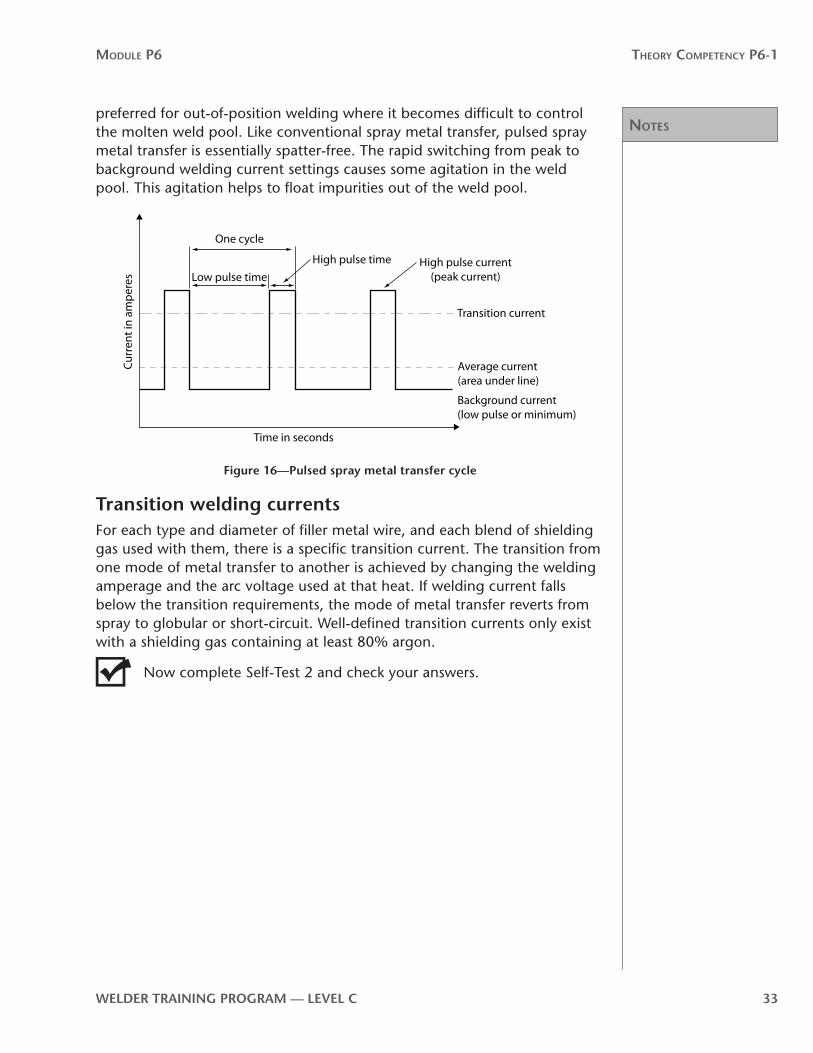
The combination of the two currents produces a steady arc (due to the background current) with a controlled transfer of weld metal in the spray mode at the pulsed peak welding current (Figure 16). The pulsed peak current level should be set just above the minimum required for spray transfer.
The pulsed spray metal transfer mode allows for a much lower average welding current than that used in conventional spray metal transfer. This extends the advantages of spray metal transfer to lighter gauges of metal, where burn-through is often a problem. Pulsed spray metal transfer is also
Notes
Module P6 Theory CoMPeTenCy P6-1
WelDer TrAInInG PrOGrAM — level C 33
preferred for out-of-position welding where it becomes difficult to control the molten weld pool. Like conventional spray metal transfer, pulsed spray metal transfer is essentially spatter-free. The rapid switching from peak to background welding current settings causes some agitation in the weld pool. This agitation helps to float impurities out of the weld pool.
Curr
ent i
n am
pere
s
Time in seconds
One cycle
Low pulse timeHigh pulse time High pulse current
(peak current)
Transition current
Average current (area under line)
Background current (low pulse or minimum)
Figure 16—Pulsed spray metal transfer cycle
Transition welding currentsFor each type and diameter of filler metal wire, and each blend of shielding gas used with them, there is a specific transition current. The transition from one mode of metal transfer to another is achieved by changing the welding amperage and the arc voltage used at that heat. If welding current falls below the transition requirements, the mode of metal transfer reverts from spray to globular or short-circuit. Well-defined transition currents only exist with a shielding gas containing at least 80% argon.
Now complete Self-Test 2 and check your answers.
Answers
Module P6 Theory CoMPeTenCy P6-1
34 WelDer TrAInInG PrOGrAM — level C
Self-Test 2Choose the best answer for each of the following questions.
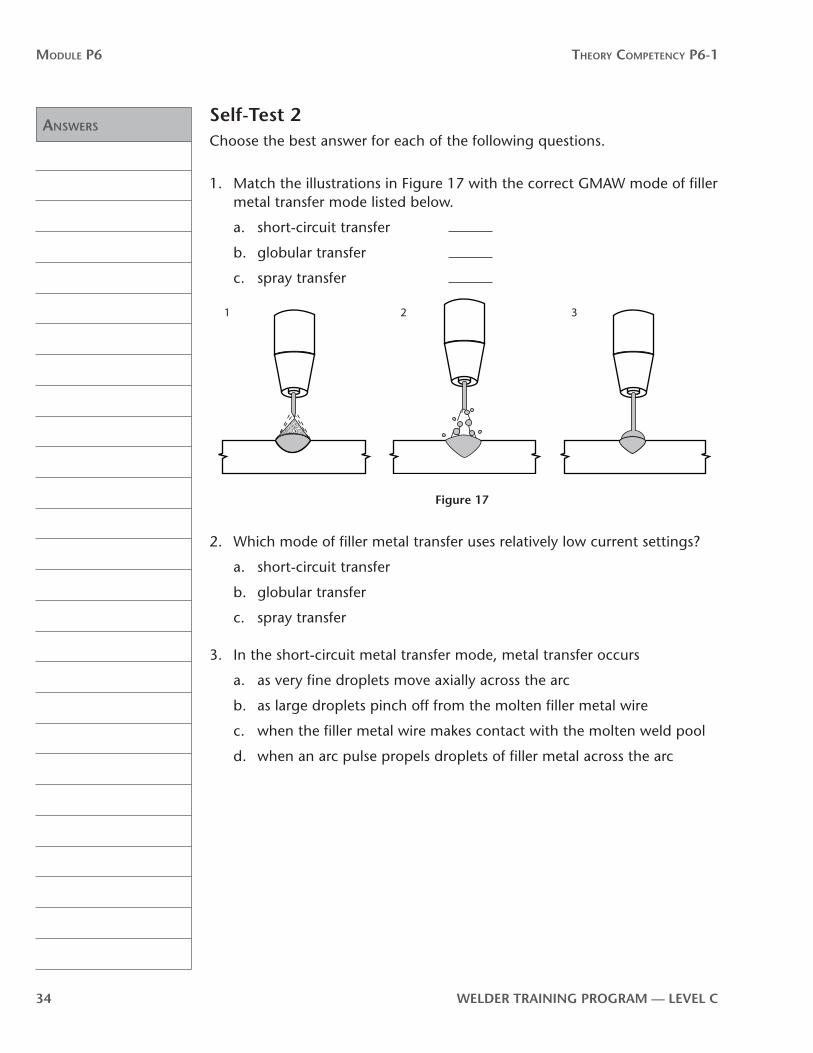
1. Match the illustrations in Figure 17 with the correct GMAW mode of filler metal transfer mode listed below.
a. short-circuit transfer
b. globular transfer
c. spray transfer
1 2 3
Figure 17
2. Which mode of filler metal transfer uses relatively low current settings?
a. short-circuit transfer
b. globular transfer
c. spray transfer
3. In the short-circuit metal transfer mode, metal transfer occurs
a. as very fine droplets move axially across the arc
b. as large droplets pinch off from the molten filler metal wire
c. when the filler metal wire makes contact with the molten weld pool
d. when an arc pulse propels droplets of filler metal across the arc

Answers
Module P6 Theory CoMPeTenCy P6-1
WelDer TrAInInG PrOGrAM — level C 35
4. For the GMAW process shown in Figure 18, at which point is the arc extinguished?
a. 1 and 2
b. 3 and 4
c. 1 and 5
d. 2 and 4
0
0
1 2 3 4 5
Figure 18
5. For the GMAW process shown in Figure 18, at which point does arc re-initiation occur?
a. 1
b. 2
c. 3
d. 4
e. 5
6. With GMAW in globular metal transfer mode, metal transfer occurs as
a. large, irregularly shaped droplets across the arc
b. the molten tip of the filler metal wire makes contact with the weld pool
c. a very fine spray directed axially at the weld pool
d. the arc pulses, propelling large droplets of filler metal across the arc

Answers
Module P6 Theory CoMPeTenCy P6-1
36 WelDer TrAInInG PrOGrAM — level C
7. With GMAW in spray metal transfer mode, metal transfer occurs as
a. large, irregularly shaped droplets across the arc
b. the molten tip of the filler metal wire makes contact with the weld pool
c. a very fine spray directed axially at the weld pool
d. the arc pulses, propelling large droplets of filler metal across the arc
8. GMAW short-circuit metal transfer is mainly used to weld
a. virtually all metals, other than cast iron
b. ferrous metals
c. thin-gauge aluminum
d. most non-ferrous metals
9. Short-circuit metal transfer can be used for welding in all positions.
a. true
b. false
10. Which of the following occurs when the current level falls below the transition welding current?
a. globular metal transfer changes to short-circuit metal transfer
b. short-circuit metal transfer changes to globular metal transfer
c. globular metal transfer changes to spray metal transfer
d. spray metal transfer reverts to short-circuit metal transfer
11. Globular metal transfer is characterized by
a. high deposition rates
b. smooth bead surface
c. light slag formation
d. an erratic arc and high spatter
12. The mode of metal transfer generally used with FCAW is
a. short-circuit
b. globular
c. spray
d. pulsed spray

Answers
Module P6 Theory CoMPeTenCy P6-1
WelDer TrAInInG PrOGrAM — level C 37
13. For out-of-position welding on aluminum, spray metal transfer
a. is not possible
b. is generally restricted to small-diameter electrodes
c. is generally restricted to large-diameter electrodes
d. can be done in all positions
14. Spray metal transfer is generally restricted to flat and horizontal fillet welding because
a. the cathode jet prevents the droplets from separating in out-of-position welding
b. the weld puddle is large and difficult to control in out-of-position welding
c. increased spatter causes arc instability in out-of-position welding
d. the force of gravity deflects the droplets in out-of-position welding
15. Which of the following modes of metal transfer is best suited to out-of-position welding?
a. globular
b. spray
c. pulsed spray
d. transition
16. Spray metal transfer is only possible when the shielding gas contains at least
a. 80% argon
b. 80% carbon dioxide
c. 80% helium
d. 80% oxygen
17. Which of the following factors determines the transition current?
a. the voltage setting
b. the type and size of electrode
c. the shielding gas flow rate
d. the thickness and the condition of the base metal

Answers
Module P6 Theory CoMPeTenCy P6-1
38 WelDer TrAInInG PrOGrAM — level C
18. Spray metal transfer is only possible when the welding current is
a. DCEN
b. pulsed DCEP
c. DCEP
d. pulsed DCEN
now go to the Answer Key and check your answers
Notes
Module P6 Theory CoMPeTenCy P6-1
WelDer TrAInInG PrOGrAM — level C 39
P6-1 learning Task 3: Safety requirements for semi-automatic welding processesAs with all arc welding processes, you must take great care to protect yourself from receiving an electric shock.
The electric currents used in GMAW are very high. If you become part of the electric circuit at any point, you could receive an electric shock severe enough to kill you. Even a small shock that is not immediately fatal could be sufficient to cause you to jerk or fall, leading to a serious injury.
Protect yourself from dangerous electrical shock by following these rules:
1. The electrode and work (or ground) circuits are electrically “hot” when the power source is on. Never permit contact between “hot” parts of the circuits and bare skin or wet clothing.
Wear dry, hole-free gloves to insulate your hands.
2. Always insulate yourself from the welding curcuit by using some form of dry electrical insulation. Welding in damp locations, on metal floors, gratings and scaffolds, or in positions such as sitting or laying down increase the possibility of electrical shock. Make certain that the electrical insulation you are using is large enough to cover your full area of physical contact with the workpiece and the work area.
3. Always be sure the work lead ground clamp makes a good electrical connection with the workpiece. The connection should also be positioned as close as possible to the welding arc as practical.
4. As a precaution it is a good idea to ground your workpiece, or the structure you are welding on, with a secoundary ground to earth. This earth ground is meant to be a safety precaution similar to a lightning rod and is not meant to be a part of the welding circuit.
5. Maintain the filler metal wire-feed system, ground clamp, welding lead cables and welding power source in good, safe operating condition.
6. When working above floor level, use personal fall protection equipment to protect yourself in the event that you get a shock and fall.

Notes
Module P6 Theory CoMPeTenCy P6-1
40 WelDer TrAInInG PrOGrAM — level C
Initial electrical isolation of shock victims If one of your fellow workers receives an electric shock, it is essential
to remove the victim from contact with the power source as soon as you can. Do not touch the victim if he or she is still in contact with the live source of electrical power. To do so or even to come close to the victim could put you in danger of electrical shock and leave you powerless to help.
If you know that the power switch is nearby, disconnect the circuit. If you do not know where the power switch is or if it is not close by, send someone else to disconnect the power, and at the same time, send for emergency medical aid. In the meantime, find some non-conductive material such as a length of dry wood, some rope or a blanket and try to pull or pry the conductor from the victim. For more detailed instructions in the procedures to use in cases of electrical shock, refer to P1-2 LT2 and go to WorkSafeBC’s website, www.worksafebc.com, and click on OHS Regulation under the Quick Links.
Safe handling of shielding gas cylinders and pressure regulatorsAlways handle compressed gas cylinders carefully. When you are using them, make sure they are properly secured. Knocks, falls or rough handling can damage the cylinders, valves or safety devices and cause leakage or an accident. Cylinder valve protective caps should be hand tightened and kept in place until the cylinder is secured and put into service.
Follow these rules when setting up and using cylinders of shielding gas:
1. Properly secure the cylinder.
2. Before you connect a cylinder pressure regulator to the cylinder valve, crack open and immediately close the valve to clear it of dust or dirt that otherwise might enter the regulator.
When opening a cylinder valve, you should stand to one side of the valve, never in front of it.
3. Release the working pressure adjusting screw on the cylinder pressure regulator by turning it counter-clockwise. The flowmeter adjusting valve should be set to closed. Then open the cylinder valve slowly to prevent a rapid surge of high-pressure gas into the cylinder pressure regulator. Again, stand to one side of the valve as you open it.
4. Always shut off the source of the shielding gas supply to the pressure regulator if it will be left unattended.

Notes
Module P6 Theory CoMPeTenCy P6-1
WelDer TrAInInG PrOGrAM — level C 41
Toxic gasesThe main toxic gases associated with GMAW are ozone, nitrogen dioxide and carbon monoxide. Dangerous gas could also be present as a result of thermal or ultraviolet decomposition of cleaning agents located in the vicinity of welding operations.
Degreasing or other cleaning operations should be done in a place where vapours from these operations cannot reach radiation from the welding arc.
OzoneThe ultraviolet light emitted by the GMAW arc acts on the oxygen in the surrounding atmosphere to produce ozone. The amount of ozone produced depends on the intensity and wavelength of the ultraviolet energy, the humidity and the amount of screening provided by any welding fumes. The ozone concentration will increase as the welding current increases, with the use of argon as the shielding gas and when welding highly reflective metals such as stainless steel and aluminum.
If the ozone cannot be reduced to a safe level by ventilation or changing the process, supply fresh air to the Welder with an air-supplied respirator or by other means.
nitrogen dioxideSome test results show that high concentrations of nitrogen dioxide are found only within 150 mm (6 in.) of the welding arc. With normal natural ventilation, these concentrations are quickly reduced to safe levels in the Welder’s breathing zone, as long as the Welder’s head stays out of the plume of fumes (and thus out of the plume of welding-generated gases).
Carbon monoxideThe heat of the welding arc in the GMAW process breaks down the carbon dioxide shielding to form carbon monoxide. The welding process creates only a small amount of carbon monoxide, but the plume of fumes temporarily contains relatively high concentrations of fumes. However, the hot carbon monoxide oxidizes to carbon dioxide so that the concentrations of carbon monoxide become insignificant at distances of more than 75 to 100 mm (3 to 4 in.) from the welding plume.
Under normal welding conditions there should be no hazard from carbon monoxide. But you will need adequate ventilation to deflect the plume or to remove the fumes and gases if you are working in a confined space or if you must work with your head over the welding arc where natural ventilation moves the plume of fumes toward your breathing zone.

Notes
Module P6 Theory CoMPeTenCy P6-1
42 WelDer TrAInInG PrOGrAM — level C
Metal fumesThe welding fumes generated by GMAW and FCAW can be controlled by general ventilation, by local exhaust ventilation or by respiratory protective equipment.
The method of ventilation required to keep the level of toxic substances within the Welder’s breathing zone at acceptable concentrations depends directly on a number of factors. Among these are the material being welded, the size of the work area and the degree of confinement or obstruction to normal air movement where the welding is being done. Each operation should be evaluated separately in order to determine what type of ventilation will be required.
Good ventilation is especially important when you are using self-shielded wires in the FCAW process. These filler metals distill fumes high in metal particles and fluoride oxides. You should take extra precautions (such as CSA-approved respiratory protective equipment) to avoid inhaling them.
Shielding gasesShielding gases used in GMAW and FCAW can displace oxygen and cause lung damage or death from suffocation. Always ensure that there is sufficient ventilation. Take special care and attention in confined spaces.
Protection against radiationThe total radiation, radiant energy, produced by the GMAW process can be higher than that produced by the SMAW process, because of the significantly lower amounts of welding fumes and the more exposed welding arc. Generally, the highest ultraviolet radiant energy intensities are produced when using an argon shielding gas and when welding on aluminum. Refer to P1-2 LT3 and go to WorkSafeBC’s website, www.worksafebc.com, and click on OHS Regulation under the Quick Links.
The minimum suggested filter lens shades for GMAW and FCAW range from 10 to 12, depending on the welding current level.
Non-reflective, fire-retardant clothing is recommended for GMAW. Reflection of ultraviolet radiation can cause ultraviolet burns to the face and neck underneath the helmet. The greater intensity of the ultraviolet radiation will cause rapid disintegration of untreated cotton clothing. CSA-approved safety eyewear must always worn. Protect other people in the work area from ultraviolet radiation with suitable non-flammable, non-reflective welding screens.
General precautions for arc welding1. Have all installation, operation, maintenance and repair work performed
by qualified people.

Notes
Module P6 Theory CoMPeTenCy P6-1
WelDer TrAInInG PrOGrAM — level C 43
2. Remove fire hazards from the work area. If this is not possible, cover them to prevent the welding sparks from starting a fire. Remember that welding sparks and hot materials from welding operations can easily go through small cracks and openings to adjacent areas. Have appropriate fire extinguishing equipment readily available.
3. When the welding power source is switched on (energized), make certain that the electrode lead cable and filler metal wire cannot make electrical contact with the workpiece or ground. Remember to position the welding gun so that the trigger cannot be accidently activated. Electical contact can cause overheating resulting in personal injury, fire hazards or damage to the workpiece.
4. Droplets of molten slag and metal are projected from the welding arc. Protect yourself with oil-free fire resistant protective garments such as leather gloves, a heavy shirt, cuffless trousers, CSA apporoved high top work boots and a cap over your head. Wear CSA approved hearing protection (ear plugs) when welding out-of-position or in confined places. Use CSA approved safety glasses with side shields when near a welding work area or welding operations.
5. Be sure the work lead cable ground clamp is connected to the work as close to the welding arc as practical. Connecting work lead cables to the building framework or other locations some distance from the welding arc increases the possibility of the welding current passing through lifting chains, crane cables or other alternate circuits. This can create fire hazards or overheat lifting chains or cables to the point of failure.
6. Make sure you have adequate protection against high noise levels. Use CSA-approved hearing protection if high noise levels are present.
7. Many industries and situations require a Firewatcher to be posted during welding operations and for specified amounts of time afterward. Refer to P1-2 LT 5 and go to WorkSafeBC’s website, www.worksafebc.com and click on OHS Regulation under the Quick Links.
8. When running filler metal wire through the welding gun assembly, be careful and watch as the wire comes out of the contact tip. There is a danger of getting poked by the sharp tip of the wire or running the wire into some object.
9. Wire feeder drive rolls should be changed, adjusted or cleaned only when the wire feeder is shut off. If the wire feeder is energized, you risk having your fingers crushed between the drive rolls.
Complete Self-Test 3 and check your answers.

Answers
Module P6 Theory CoMPeTenCy P6-1
44 WelDer TrAInInG PrOGrAM — level C
Self-Test 3Choose the best answers for the following questions.
1. To reduce reflection of ultraviolet radiation while welding, you should wear clothing that is
a. dark in colour
b. light in colour
c. made of heavyweight canvas
d. made of polyester
2. Which of the following is an essential precaution against electrical shock?
a. make sure cylinder valve caps are in place when the cylinder is not in use
b. lock out the welding power source when you change the wire-feeder drive rolls
c. ensure that the workpiece is electrically grounded to earth
d. wear plastic or rubber-lined boots
3. Which toxic gas is created when carbon dioxide is subjected to the heat of the welding arc?
a. carbon monoxide
b. phosgene
c. carbon nitrate
d. hydrocarbon
4. Define the term “arc flash.”
5. For all grinding operations, you must wear CSA approved safety glasses and
a. flash goggles
b. welding goggles
c. face shield
d. welding helmet
6. What must you inspect your shaded filter lenses for before you begin to weld?

Answers
Module P6 Theory CoMPeTenCy P6-1
WelDer TrAInInG PrOGrAM — level C 45
7. What kind of footwear is required in the welding shop?
a. CSA-approved leather work boots
b. oxfords
c. CSA-approved running shoes
d. rubber boots
8. Combustible materials that cannot be removed from the work area where you must weld should be
a. coated with fire-retardant spray
b. effectively screened from the welding arc
c. soaked with water
d. identified with appropriate signs
9. When you inspect welding lead cables before welding and find breaks in the insulation, you should
a. flag them for repair when you finish up
b. discard the cables
c. repair the cables with the proper electrical tape
d. coat the cables with fire retardant
10. When your welding power source is energized, but you have finished welding, you should always
a. position the welding gun so that the trigger cannot be accidently activated
b. remove the welding filler metal wire from the welding gun
c. disconnect the work lead ground cable
d. make sure the current setting is below 50 A
11. You must avoid touching a victim of electrical shock if he or she is still in contact with the source of power and if the
a. victim is still moving
b. source of power is still energized
c. victim is not moving
d. source of power is de-energized and locked out

Answers
Module P6 Theory CoMPeTenCy P6-1
46 WelDer TrAInInG PrOGrAM — level C
12. Which shades of filter lens are recommended for GMAW and FCAW?
a. 8 to 10
b. 10 to 12
c. 12 to 15
d. 15 to 18
13. The specific filter lens shade within the range recommended is determined by the
a. welding current level
b. electrode stickout
c. type of shielding gas used
d. type of welding power source
now go to the Answer Key and check your answers

Theory CompeTenCy p6-2:GMAW, GMAW-P, FCAW, MCAW and SAW equipment and their operation
p6
-2


WelDer TrAInInG PrOGrAM — level C 49
Module P6 Theory CoMPeTenCy P6-2
OutcomesIn order to produce effective and high-quality welds using the GMAW, FCAW and SAW processes, you must thoroughly understand the equipment, its components, how they operate, and the adjustments you will be required to make. In particular, you need to thoroughly understand the relationship between welding current and arc voltage with both constant voltage (CV) and constant current (CC) power sources. A thorough knowledge of filler metal electrode wire-feed mechanisms is also very important.
When you have completed the Learning Tasks in this Theory Competency, you should be able to describe the:
• volt-ampere curves for CC and CV welding power sources• equipment for the SAW process• self-correcting arc length characteristic of CV welding power sources• function of slope and inductance in CV welding power sources• operation of pulsed-current welding power sources• types of filler metal electrode wire-feed systems• advantages and disadvantages of filler metal electrode wire-feed systems• welding gun assemblies for semi-automated processes• process-related weld discontinuities and their causes
evaluationWhen you have completed all the Theory Competencies in module P6, you will take a written test. You must score at least 70% on this test. The test will include questions that are based on the following material from Competency P6-2:
• the welding power sources for semi-automated and automated processes
• filer metal electrode wire-feed systems for semi-automated and automated processes
• welding gun assemblies for semi-automated and automated processes
resourcesRequired: All the required resources for this Theory Competency are contained within this Competency.

50 WelDer TrAInInG PrOGrAM — level C

Notes
Module P6 Theory CoMPeTenCy P6-2
WelDer TrAInInG PrOGrAM — level C 51
P6-2 learning Task 1:Welding power sources for semi-automatic processesA direct current, constant voltage (constant potential) power source is commonly used for GMAW and FCAW. This is in contrast to SMAW and GTAW, which use constant current power sources. Most GMAW applications use direct current electrode positive (DCEP). This means that the positive work lead cable is connected to the welding gun and the negative work lead cable is connected to the workpiece.
The types of direct current welding power sources normally used for semi-automatic processes are the motor-generator, the transformer-rectifier and the inverter. The transformer-rectifier and inverter types are usually preferred for in-shop fabrication where a source of electrical line power is available. The engine-driven power source can be used where there is no other source of electrical line power, such as the jobsite in the field.
Constant voltage welding power sourcesThe development of constant voltage (constant potential) welding power sources has greatly increased the applications of metal arc welding. Before they were developed, constant current welding power sources were used along with arc voltage-sensing filler metal wire-feed systems. However, the slow response time of these setups meant burnback or stubbing caused problems when using smaller diameter filler metal wire.
Constant voltage welding power sources (Figure 19) with constant speed wire feeders respond much more quickly to changes in welding conditions.
Figure 19—Constant voltage power source

Notes
Module P6 Theory CoMPeTenCy P6-2
52 WelDer TrAInInG PrOGrAM — level C
The dynamics or response characteristics of the CV machine can be shown on a typical CV volt-ampere curve. The volt-ampere curve for CV machines is flatter than the volt-ampere curve for CC power sources (Figure 20).
Operating point
Volta
ge (V
)
Current (A)
Constant current power source
Operating point
Volta
ge (V
)
Current (A)
Constant voltage power source
Figure 20—volt-ampere curves
If the load in the welding circuit changes, welding current output will fluctuate dramatically, but arc voltage will remain stable. The graph in Figure 21 shows that if the arc voltage drops only 2 V, the welding current will increase 100 A.
Volta
ge (V
)
Current (A)
CV machine output curve
100 A
2 V
Figure 21—Welding current fluctuation
The flat volt-ampere curve of CV welding power sources combined with a fixed filler metal wire-feed speed gives the system its responsiveness to assure a self-correcting arc length. Adjusting the output voltage of the power source allows you to set your desired arc length. The filler metal wire-feed speed, which also becomes the welding current control, is also set before starting to weld.
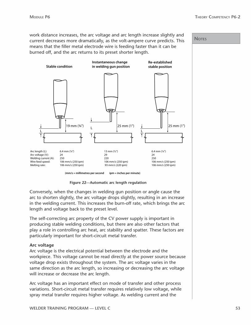
When the contact tip to work distance changes, as it does when you change position or welding gun angle during welding, the welding power source automatically increases or decreases current, while maintaining a constant arc voltage and a constant arc length (Figure 22). As the contact tip to
Notes
Module P6 Theory CoMPeTenCy P6-2
WelDer TrAInInG PrOGrAM — level C 53
work distance increases, the arc voltage and arc length increase slightly and current decreases more dramatically, as the volt-ampere curve predicts. This means that the filler metal electrode wire is feeding faster than it can be burned off, and the arc returns to its preset shorter length.
LL
L
Re-established stable position
Instantaneous change in welding gun positionStable condition
19 mm (¾") 25 mm (1") 25 mm (1")
Arc length (L): 6.4 mm (¼") 13 mm (½") 6.4 mm (¼")Arc voltage (V): 24 29 24Welding current (A): 250 220 250Wire feed speed: 106 mm/s (250 ipm) 106 mm/s (250 ipm) 106 mm/s (250 ipm)Melting rate : 106 mm/s (250 ipm) 93 mm/s (220 ipm) 106 mm/s (250 ipm)
(mm/s = millimetres per second ipm = inches per minute)
Figure 22—Automatic arc length regulation
Conversely, when the changes in welding gun position or angle cause the arc to shorten slightly, the arc voltage drops slightly, resulting in an increase in the welding current. This increases the burn-off rate, which brings the arc length and voltage back to the preset level.
The self-correcting arc property of the CV power supply is important in producing stable welding conditions, but there are also other factors that play a role in controlling arc heat, arc stability and spatter. These factors are particularly important for short-circuit metal transfer.
Arc voltageArc voltage is the electrical potential between the electrode and the workpiece. This voltage cannot be read directly at the power source because voltage drop exists throughout the system. The arc voltage varies in the same direction as the arc length, so increasing or decreasing the arc voltage will increase or decrease the arc length.
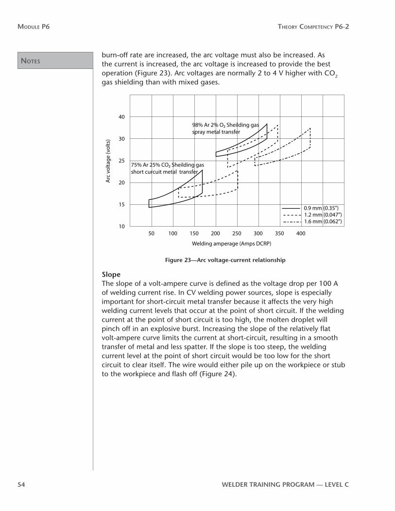
Arc voltage has an important effect on mode of transfer and other process variations. Short-circuit metal transfer requires relatively low voltage, while spray metal transfer requires higher voltage. As welding current and the
Notes
Module P6 Theory CoMPeTenCy P6-2
54 WelDer TrAInInG PrOGrAM — level C
burn-off rate are increased, the arc voltage must also be increased. As the current is increased, the arc voltage is increased to provide the best operation (Figure 23). Arc voltages are normally 2 to 4 V higher with CO2 gas shielding than with mixed gases.
5010
15
20
25
30
40
100 150 200 250 300 350 400
Arc
vol
tage
(vol
ts)
Welding amperage (Amps DCRP)
0.9 mm (0.35")1.2 mm (0.047")1.6 mm (0.062")
75% Ar 25% CO2 Sheilding gas short curcuit metal transfer
98% Ar 2% O2 Sheilding gas spray metal transfer
Figure 23—Arc voltage-current relationship
SlopeThe slope of a volt-ampere curve is defined as the voltage drop per 100 A of welding current rise. In CV welding power sources, slope is especially important for short-circuit metal transfer because it affects the very high welding current levels that occur at the point of short circuit. If the welding current at the point of short circuit is too high, the molten droplet will pinch off in an explosive burst. Increasing the slope of the relatively flat volt-ampere curve limits the current at short-circuit, resulting in a smooth transfer of metal and less spatter. If the slope is too steep, the welding current level at the point of short circuit would be too low for the short circuit to clear itself. The wire would either pile up on the workpiece or stub to the workpiece and flash off (Figure 24).

Notes
Module P6 Theory CoMPeTenCy P6-2
WelDer TrAInInG PrOGrAM — level C 55
Wire
Weld bead
Too much (steep) slope Too little (�at) slope
Figure 24—effect of slope
When the peak short-circuit current is at the correct value, the parting of the molten drop from the filler metal electrode wire is smooth with very little spatter. The chart (Figure 25) shows typical peak short-circuit currents required for metal transfer with the best arc stability. These short-circuit current levels are typical of a medium slope setting.
Filler metal electrode wire material
Filler Metal electrode wire diameter
Peak short-circuit welding current
metric imperial (DCEP)
Carbon steel 0.8 mm 0.030 in. 300 A
Carbon steel 0.9 mm 0.035 in. 320 A
Aluminum 0.8 mm 0.030 in. 175 A
Aluminum 0.9 mm 0.035 in. 195 A
Figure 25—Peak currents for short-circuit metal transfer
InductanceInductance is a circuit characteristic of most CV power sources. Its function is to lengthen the response time of the welding power source to changes in the load (Figure 26).
Curve A - Inductance added
Curve B - No Inductance
Time (seconds)
Curr
ent (
ampe
res)
Figure 26—effect of inductance

Notes
Module P6 Theory CoMPeTenCy P6-2
56 WelDer TrAInInG PrOGrAM — level C
Curve A, with inductance added, shows a typical welding current-time curve as the current rises from zero to a final value. Curve B shows the path the welding current would take if there were no inductance in the circuit. The maximum force of the pinch effect depends on the short-circuit current, which is limited by the slope characteristic of the welding power source circuit.
The rate of welding current rise at the point of short circuit is also important to smooth transfer. This rate of increase is limited by the inductance of the welding power source. If the current rises too rapidly, the pinch effect will be too forceful and the molten drop will explode off the filler metal electrode, causing high spatter. Inductance slows down the rate of welding current rise. This decreases the number of short circuits per second and increases the arc-on time. The result is a more fluid weld pool, and a flatter, smoother weld bead. In spray metal transfer welding, the addition of some inductance to the power source produces a softer start without reducing the final amount of welding current available. Too much inductance will result in filler metal electrode stubbing on the start.
When correct short-circuit welding current levels and rates of welding current rise are maintained, the arc is stable and spatter is minimal. The welding power source adjustments for optimal conditions depend on the filler metal electrode material and diameter. As a general rule, both the amount of short-circuit welding current and the amount of inductance needed for the ideal pinch effect increase as the filler metal electrode diameter increases.
Types of controls on Cv welding power sourcesAll constant voltage welding power sources have a voltage control, and some also have controls for slope and inductance. The welding current is changed by adjusting the filler metal wire-feed speed.
voltage controlsVoltage controls on CV welding power sources vary according to the make and model of the power source, but the result is always the same. Voltage adjustments increase or decrease the arc voltage but do not affect the shape of the volt-ampere curve. CV welding power sources provide a continuous voltage control. The filler metal electrode wire diameter, the type of shielding gas, the base metal material thickness and the mode of transfer determine the output voltage setting parameters.
Slope controlsOn some CV welding power sources the slope is fixed, which means a certain amount of slope is designed into the power source to suit the majority of welding applications. Variable slope welding power sources, on the other hand, permit the Welder to modify the slope of the volt-ampere curve (Figure 27). On this type of power source, the basic volt-ampere curve is relatively flat and adjustments can be made by a tapped or a continuous control similar to the variable voltage controls.

Notes
Module P6 Theory CoMPeTenCy P6-2
WelDer TrAInInG PrOGrAM — level C 57
Volta
ge
Current
Maximum slope Infinite slope adjustment
Figure 27—Slope of volt-ampere curve
Inductance controlsInductance controls the rate of current rise. Like slope, inductance on many welding power sources is fixed and the Welder makes no adjustment. On other welding power sources, inductance is variable. This is particularly important in short-circuit metal transfer welding in order to control weld spatter. Controls for inductance can be tapped or continuous and are similar to those used for slope and voltage control.
Current controlsConstant voltage welding power sources have no controls for welding current instead, current level is a function of slope, and responds to the filler metal wire-feed speed. The welding power source automatically adjusts welding current in response to changes in arc length, which directly affects arc voltage. This ensures a constant arc length.
voltmeters and ammetersVoltmeters and ammeters are standard on most CV welding power source units. Their purpose is to help you when setting up the correct welding conditions for a given job.
The voltmeter will read the selected output voltage when the welding power source is energized but not being used. Once the arc is initiated, the voltmeter will read the load voltage. (Figure 28 shows typical voltage readings.) True arc voltage is generally 2 to 5 V lower than load voltage and can only be measured at the arc. (Figure 29 shows the setup for measuring true arc voltage.)
No load Load voltage
Figure 28—voltmeter readings

Notes
Module P6 Theory CoMPeTenCy P6-2
58 WelDer TrAInInG PrOGrAM — level C
Figure 29—Measuring true arc voltage
voltage sensingSome welding power sources have a voltage-sensing device that will read the difference in potential and automatically adjust the voltage as required by the initial settings of the filler metal wire feeder.
The ammeter (Figure 30) indicates the welding amperage at the output terminals of the welding power source.
No load Load amperage
Figure 30—Ammeter and voltmeter readings
remote controls and dual schedulesMost CV welding power sources have remote control receptacles. These allow a Welder who is some distance from the welding power source and filler metal wire feed drive unit to control output voltage, wire-feed speed and, in some cases, shielding gas flowrate and water flow (if necessary). A dual schedule control panel (Figure 31) provides two individual preset output voltage and wire-feed speed schedules that can be used during welding. A quick “engage-disengage” squeeze of the welding gun trigger switch changes from one schedule to the other.

Notes
Module P6 Theory CoMPeTenCy P6-2
WelDer TrAInInG PrOGrAM — level C 59
Figure 31—Dual schedule control panel
Constant current welding power sourcesThe filler metal wire feeder for a constant current welding power source has a variable speed drive motor. It receives feedback from the arc voltage to adjust the filler metal wire feed speed so that the selected arc length is maintained. The main drawback with this type of system involves starting the arc. With CV welding power sources, the current at the point of short-circuit is very high and the arc will start easily. With CC welding power sources, the current at the point of short-circuit is too low to properly establish the arc. To overcome problems with arc starting, the filler metal wire feeder must have a slow run-in feature for starting the arc and then switch to full speed once the arc is established.
Pulsed current welding power sourcesPulsed current welding power sources make possible a much wider application of the spray metal transfer mode for out-of-position welding. With traditional techniques, the continuous high welding current that is required produces a weld pool that cannot be retained in out-of-position applications. This means that, except for aluminum, spray metal transfer is generally limited to the flat position.
Inverter type welding power sources are used for the GMAW-P process. Inverter technology allows for smaller power sources capable of better performance.
Inverter type welding power sources increase the frequency of incoming primary power from 60 hertz to several thousand hertz (Figure 32). Many benefits come from this high operating frequency (not to be confused with pulse frequency) and other solid-state devices used in the inverter type welding power source.

noTes
Module P6 Theory CoMPeTenCy P6-2
60 WelDer TrAInInG PrOGrAM — level C
1
2
3
4
5
6
7
input line voltage 60 cycles per second (Hz)
rectifier: DC ripple current
filter: smooth DC current
inverter: high-frequency AC current 20 000 Hz
transformer: low-voltage high-frequency AC current
rectifier: ripple DC low-voltage current
filter: smooth low-voltage welding current
Figure 32—Process steps in an inverter power source
The most important benefit of inverter type welding power sources used for GMAW-P is rapid response time. A rapid response time allows for precise control of welding output power. The short time between each cycle allows for this control. Parameters such as peak current (heat), background current (arc stability), pulse frequency and pulse width (time) can be varied easily and controlled accurately.
In pulsed spray metal transfer, the arc energy rapidly pulsates between high welding current and low background current (Figure 33).
Curr
ent i
n am
pere
s
Time in seconds
One cycle
Low pulse timeHigh pulse time High pulse current
(peak current)
Transition current
Average current (area under line)
Background current (low pulse or minimum)
Figure 33—Arc energy
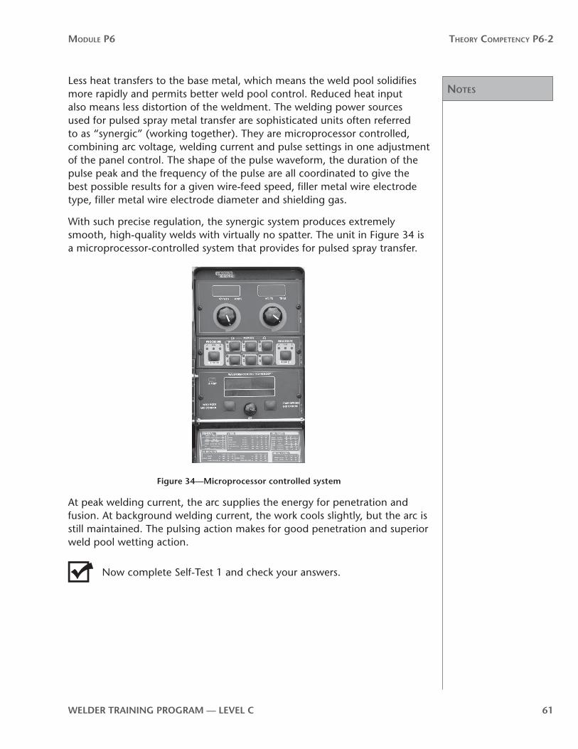
noTes
Module P6 Theory CoMPeTenCy P6-2
WelDer TrAInInG PrOGrAM — level C 61
Less heat transfers to the base metal, which means the weld pool solidifies more rapidly and permits better weld pool control. Reduced heat input also means less distortion of the weldment. The welding power sources used for pulsed spray metal transfer are sophisticated units often referred to as “synergic” (working together). They are microprocessor controlled, combining arc voltage, welding current and pulse settings in one adjustment of the panel control. The shape of the pulse waveform, the duration of the pulse peak and the frequency of the pulse are all coordinated to give the best possible results for a given wire-feed speed, filler metal wire electrode type, filler metal wire electrode diameter and shielding gas.
With such precise regulation, the synergic system produces extremely smooth, high-quality welds with virtually no spatter. The unit in Figure 34 is a microprocessor-controlled system that provides for pulsed spray transfer.
Figure 34—Microprocessor controlled system
At peak welding current, the arc supplies the energy for penetration and fusion. At background welding current, the work cools slightly, but the arc is still maintained. The pulsing action makes for good penetration and superior weld pool wetting action.
Now complete Self-Test 1 and check your answers.

Answers
Module P6 Theory CoMPeTenCy P6-2
62 WelDer TrAInInG PrOGrAM — level C
Self-Test 1Choose the best answer for each of the following questions.
1. Which type of welding power source is most often used for GMAW and FCAW?
a. AC
b. CC
c. CV
d. CD
2. Which type of welding current is most commonly used for GMAW applications?
a. AC
b. ACEP
c. DCEN
d. DCEP
3. The volt-ampere curve shown in Figure 35 is characteristic of which type of welding power source(s)?
a. constant current
b. constant voltage
c. constant potential
d. alternating current
Operating point
Volta
ge (V
)
Current (A)
Constant current power source
Operating point
Volta
ge (V
)
Current (A)
Constant voltage power sourceFigure 35

Answers
Module P6 Theory CoMPeTenCy P6-2
WelDer TrAInInG PrOGrAM — level C 63
4. The volt-ampere curve shown in Figure 36 is characteristic of which type of welding power source(s)?
a. constant current
b. constant voltage
c. constant potential
d. alternating current
Operating point
Volta
ge (V
)
Current (A)
Constant current power source
Operating point
Volta
ge (V
)
Current (A)
Constant voltage power sourceFigure 36
5. Constant voltage welding power sources are used with
a. constant-speed wire feeders
b. variable-speed wire feeders
c. inductance-controlled wire feeders
d. slope-controlled wire feeders
6. Which type of filler metal wire feeder is preferred for CC power sources?
a. constant-speed
b. variable-speed
c. inductance-controlled
d. slope-controlled
7. In constant voltage welding power sources, changes in arc length produce
a. marked changes in welding current
b. minimal changes in welding current
c. marked changes in arc voltage
d. minimal changes in inductance
8. In constant current welding power sources, changes in arc length

Answers
Module P6 Theory CoMPeTenCy P6-2
64 WelDer TrAInInG PrOGrAM — level C
produce
a. marked changes in welding current
b. minimal changes in welding current
c. marked changes in inductance
d. minimal changes in arc voltage
9. Constant voltage welding power sources feature
a. relatively constant amperages despite changes in arc voltage
b. relatively constant burn-off rates despite changes in welding current
c. marked changes in inductance
d. minimal changes in arc voltage
10. With a constant voltage welding power source, increases in arc length will
a. decrease arc voltage
b. decrease burn-off rate
c. increase welding current
d. increase wire-feed speed
11. With CV welding power sources, decreases in arc length will
a. increase arc voltage
b. decrease burn-off rate
c. decrease welding current
d. increase weldingcurrent
12. What is the function of slope in CV welding power sources?
a. to limit the short-circuit welding current level in order to reduce spatter
b. to decrease the arc on time in order to limit heat input
c. to minimize the arc voltage drop as a result of impedance in the system
d. to increase the number of short circuits per second

Answers
Module P6 Theory CoMPeTenCy P6-2
WelDer TrAInInG PrOGrAM — level C 65
13. What results when the slope is set too steep?
a. too high heat levels can cause distortion or burn-through
b. the pinch effect is so strong that the molten wire separates in an explosive burst
c. the short circuit cannot clear itself and wire could pile up or stub on the workpiece
d. arc length becomes so long that the voltage exceeds maximum levels and damages the circuitry of the power source
14. The purpose of increasing inductance is to
a. lengthen the response time of the welding current rise
b. increase the number of short circuits per second
c. decrease arc-on time, thereby decreasing heat input
d. limit the maximum spray metal transfer current levels
15. In general, the purpose of both slope and inductance is to
a. decrease penetration and heat input on thin materials
b. increase the speed of welding
c. decrease spatter and improve arc stability
d. provide a mechanism for spray metal transfer at lower average current levels
16. Pulsed current welding power sources were developed to
a. reduce the welding current levels required for short-circuit metal transfer
b. permit spray metal transfer at welding current levels that are, on average, below the transition current
c. increase the force of the arc and thereby increase penetration of thicker materials
d. permit a spatter-free globular metal transfer mode
17. On CV welding power sources, changes in the welding current are made by
a. adjusting the arc voltage setting
b. adjusting the slope control
c. adjusting the inductance
d. adjusting the filler metal wire-feed speed
now go to the Answer Key and check your answers

noTes
Module P6 Theory CoMPeTenCy P6-2
66 WelDer TrAInInG PrOGrAM — level C

noTes
Module P6 Theory CoMPeTenCy P6-2
WelDer TrAInInG PrOGrAM — level C 67
P6-2 learning Task 2: equipment for semi-automatic and automatic filler metal wire-feed systemsThe GMAW system requires light, flexible and durable equipment that can feed a small-diameter filler metal wire electrode at a constant rate. The feeder should also keep the filler metal wire clean and snag-free and provide controls for starting, stopping and adjusting wire-feed speed. Constant voltage welding power sources need a constant speed wire-feed, so the wire-feed speed must be adjustable for different welding currents.
There are many kinds of wire-feed units, but they generally all consist of a spool or coil of filler metal electrode wire, a set of drive feed rolls for the wire and an adjustable, constant speed motor to turn the drive rolls.
There are three types of wire-feeders for handling different types of electrode wire: the push type, the pull type and the push-pull type (Figure 37). The difference between them is in the way the drive rolls feed the electrode wire to the welding gun. The push type pushes the wire, the pull type pulls the wire and the push-pull combines both a pushing and pulling mechanism.
Push mechanism
Pull mechanism
4.5 m (15')
4.5 m (15')
9 m (30')
Push mechanismPull mechanism
Figure 37—Feed mechanisms
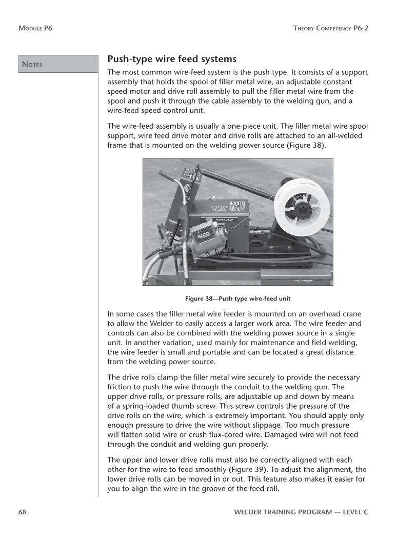
noTes
Module P6 Theory CoMPeTenCy P6-2
68 WelDer TrAInInG PrOGrAM — level C
Push-type wire feed systemsThe most common wire-feed system is the push type. It consists of a support assembly that holds the spool of filler metal wire, an adjustable constant speed motor and drive roll assembly to pull the filler metal wire from the spool and push it through the cable assembly to the welding gun, and a wire-feed speed control unit.
The wire-feed assembly is usually a one-piece unit. The filler metal wire spool support, wire feed drive motor and drive rolls are attached to an all-welded frame that is mounted on the welding power source (Figure 38).
Figure 38—Push type wire-feed unit
In some cases the filler metal wire feeder is mounted on an overhead crane to allow the Welder to easily access a larger work area. The wire feeder and controls can also be combined with the welding power source in a single unit. In another variation, used mainly for maintenance and field welding, the wire feeder is small and portable and can be located a great distance from the welding power source.
The drive rolls clamp the filler metal wire securely to provide the necessary friction to push the wire through the conduit to the welding gun. The upper drive rolls, or pressure rolls, are adjustable up and down by means of a spring-loaded thumb screw. This screw controls the pressure of the drive rolls on the wire, which is extremely important. You should apply only enough pressure to drive the wire without slippage. Too much pressure will flatten solid wire or crush flux-cored wire. Damaged wire will not feed through the conduit and welding gun properly.
The upper and lower drive rolls must also be correctly aligned with each other for the wire to feed smoothly (Figure 39). To adjust the alignment, the lower drive rolls can be moved in or out. This feature also makes it easier for you to align the wire in the groove of the feed roll.

noTes
Module P6 Theory CoMPeTenCy P6-2
WelDer TrAInInG PrOGrAM — level C 69
Pressure roll
Knurled portion
Drive roll
Pressure adjustment
In-out adjustment
Wheels adjusted; rolls in alignment with sufficient pressure
Rolls misaligned; adjust drive roll
Insufficient pressure on wire; adjust pressure
Figure 39—Feed roll alignment
The alignment between the filler metal wire guides and the drive rolls is also important. Although the wire guides are properly aligned when the unit is manufactured, over time they might need readjustment. The wire guides are mounted on the drive housing, which might move up or down, causing the guides to become misaligned (Figure 40). To realign, you need to loosen the drive housing mounting bolts and adjust the housing until the rolls and guides come into alignment. The inner end of each wire guide should be as close as possible to the drive rolls, without touching them.
Wire guideDrive roll
Drive housingHousing bolts
Drive rolls and wire guides properly aligned
Wire bent down housing and wire guides too high, lower drive housing
Wire bent up housing and wire guides too low, raise drive housing
Figure 40—Correctly and incorrectly aligned wire guides
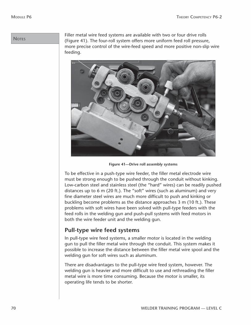
noTes
Module P6 Theory CoMPeTenCy P6-2
70 WelDer TrAInInG PrOGrAM — level C
Filler metal wire feed systems are available with two or four drive rolls (Figure 41). The four-roll system offers more uniform feed roll pressure, more precise control of the wire-feed speed and more positive non-slip wire feeding.
Figure 41—Drive roll assembly systems
To be effective in a push-type wire feeder, the filler metal electrode wire must be strong enough to be pushed through the conduit without kinking. Low-carbon steel and stainless steel (the “hard” wires) can be readily pushed distances up to 6 m (20 ft.). The “soft” wires (such as aluminum) and very fine diameter steel wires are much more difficult to push and kinking or buckling become problems as the distance approaches 3 m (10 ft.). These problems with soft wires have been solved with pull-type feeders with the feed rolls in the welding gun and push-pull systems with feed motors in both the wire feeder unit and the welding gun.
Pull-type wire feed systemsIn pull-type wire feed systems, a smaller motor is located in the welding gun to pull the filler metal wire through the conduit. This system makes it possible to increase the distance between the filler metal wire spool and the welding gun for soft wires such as aluminum.
There are disadvantages to the pull-type wire feed system, however. The welding gun is heavier and more difficult to use and rethreading the filler metal wire is more time consuming. Because the motor is smaller, its operating life tends to be shorter.

noTes
Module P6 Theory CoMPeTenCy P6-2
WelDer TrAInInG PrOGrAM — level C 71
Push-pull wire feed systemsThe push-pull wire feed system uses synchronized feed motors and drive roll assemblies located at both ends of the filler metal electrode wire conduit. A wire-feed motor and drive roll assembly located in the welding gun pulls the wire through the feed conduit, while a drive motor and drive roll assembly located in the control unit pushes the wire through the conduit to the welding gun. This system extends the possible distance between the wire feeder unit and welding gun to about 9 m (30 ft.). Compared to the pull type system, the push-pull type system has many advantages. As distances increase, softer filler metal wires can be used and load on drive motors is reduced. The main disadvantages of this system are its complexity and cost.
Spool type welding gunSome welding guns have both the filler metal wire feeder and wire spool housed in the welding gun (Figure 42). These spool type welding guns (commonly called “spool guns”) are used mostly for welding aluminum.
Figure 42—Spool type welding gun

noTes
Module P6 Theory CoMPeTenCy P6-2
72 WelDer TrAInInG PrOGrAM — level C
Filler metal wire feed drive rollsThere are several designs of wire feed drive rolls. Your choice of which to use depends on the type and diameter of the filler metal wire (Figure 43). You should follow the directions of the filler metal wire manufacturers.
Filler metal wire diameter Filler metal wire types
mm in. Hard Wire
Hard Wire
Hard and
Tubular Wire
Soft Wire
Hard and
Tubular Wire
Tubular Wire
0.024 YES YES — YES — —
0.75 0.030 YES YES — YES — —
0.9 0.035 YES YES — YES — —
1.1 0.045 YES YES — — — —
1.2 3⁄64 (0.047) — — — YES — —
1.3 0.052 YES YES — YES — YES
1.6 1⁄16 (0.063) — — YES YES YES YES
2.0 5⁄64 (0.078) — — YES YES YES YES
2.4 3⁄32 (0.094) — — YES YES YES YES
2.8 7⁄64 (0.109) — — YES YES YES YES
3.2 1⁄8 (0.125) — — YES YES YES YES
4.0 5⁄32 (0.156) — — — — YES YES
4.8 3⁄16 (0.188) — — — — YES YES
5.6 7⁄32 (0.129) — — — — YES YES
6.4 1⁄4 (0.250) — — — — YES YES
Wire feed drive roll selection
Smooth V
Flat smooth Flat knurled
Smooth V Smooth V
Smooth V
Smooth V
Smooth V
Knurled
Smooth V
Knurled
Knurled
Figure 43—Typical wire feed drive roll surfaces

noTes
Module P6 Theory CoMPeTenCy P6-2
WelDer TrAInInG PrOGrAM — level C 73
Wire-feed drive speed controlsDepending on the design of the wire-feed system, the wire-feed drive speed control for the wire-feed motor can be located on the feeder unit or on the welding gun. On many push-type systems, the controls and wire-feed motor are combined in one integrated unit. This unit provides controls for the wire-feed drive speed, shielding gas, water flow (on water-cooled systems) and welding power (contactor switch). All of these functions (along with starting the wire feed) are started and stopped by squeezing and releasing the gun trigger.
Solenoids (which control gas and water flow) are regulated to coincide with the weld start and stop. Most wire feed units have a wire feed inch control and a shielding gas purge control. These controls may be a switch type or a button type. The inch control causes the wire feed drive motor to feed the wire through the electrode conduit to the welding gun. When you are setting up, use the inch switch to feed the filler metal wire through to the contact tip and the shielding gas purge control to set the flow rate of shielding gas. When using these controls the filler metal wire is not energized with welding current as it would be if the welding gun trigger was used to perform these operations.
Some filler metal wire feeders have a feed or retract control that is used to reverse the direction of the wire feed. They might also have a shielding gas purge control to clear the system of contaminating air or moisture before you begin welding. On some, there are controls for automatic preflow and post flow of shielding gas.
Constant-speed and variable-speed filler metal wire feedersConstant-speed wire feeders are used with constant voltage power sources. For heavy industrial work, these wire feeders are usually independent of the welding power source. For lighter commercial work, the wire feeders are often built right into the welding power source. The arc voltage remains steady where set and the wire-feed speed determines the welding amperage.
Variable-speed wire feeders (Figure 44) are used with constant current welding power sources. These units are independent of the welding power source. Amperage is set at the power source and remains steady, and the arc voltage determines the wire-feed speed. A voltage-sensing clamp is attached to the workpiece, and the arc voltage is relayed back to the wire-feed drive motor, which speeds up or slows down to maintain the arc length required.

noTes
Module P6 Theory CoMPeTenCy P6-2
74 WelDer TrAInInG PrOGrAM — level C
Figure 44—variable speed wire feeder
equipment for the SAW process
Automatic and semi-automatic SAW equipmentBoth fully automatic and semi-automatic SAW equipment are available. In both the arc is submerged under a granular flux. The semi-automatic unit requires a Welder to adjust travel speed and direction as welding proceeds along the weld joint. The more common fully automatic equipment runs on a track aligned with the weld joint and drives itself at a speed set by the Welder (Figure 45). Self-propelled, trackless fully automatic submerged arc systems are more portable (Figure 46).
Figure 45—Fully automatic SAW equipment
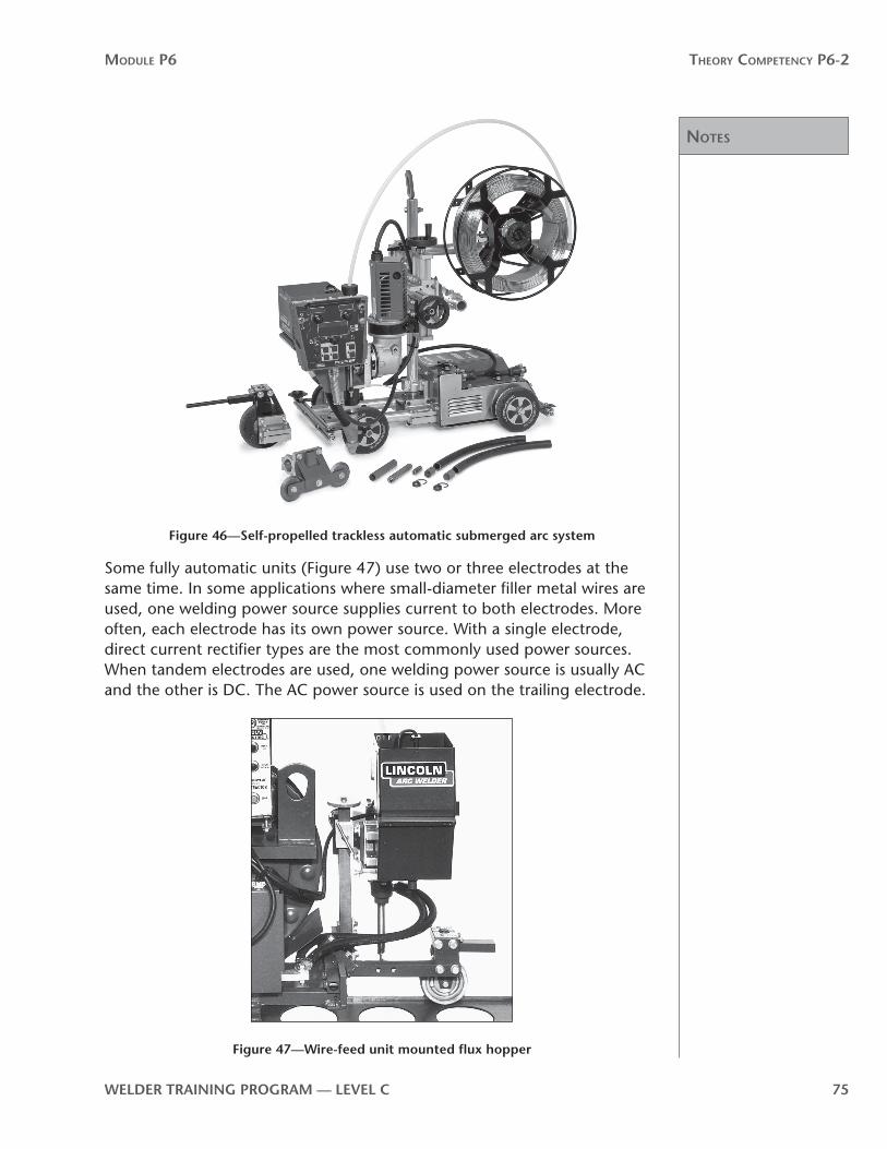
noTes
Module P6 Theory CoMPeTenCy P6-2
WelDer TrAInInG PrOGrAM — level C 75
Figure 46—Self-propelled trackless automatic submerged arc system
Some fully automatic units (Figure 47) use two or three electrodes at the same time. In some applications where small-diameter filler metal wires are used, one welding power source supplies current to both electrodes. More often, each electrode has its own power source. With a single electrode, direct current rectifier types are the most commonly used power sources. When tandem electrodes are used, one welding power source is usually AC and the other is DC. The AC power source is used on the trailing electrode.
Figure 47—Wire-feed unit mounted flux hopper

noTes
Module P6 Theory CoMPeTenCy P6-2
76 WelDer TrAInInG PrOGrAM — level C
Welding power sources of 1000 A capacity or more with a 100% duty cycle are required for welding continuously at high amperages. The welding lead cables used, both the electrode and work leads, must be large enough to carry these high currents. Using two 4/0 cables in tandem is recommended for welding up to 1200 A.
The high heat input of the welding arcs into the base metal can cause problems with burn-through. To help dissipate the heat, chill bars made of copper, sometimes with water flowing through them, are clamped to the base plate close to, or directly beneath, the weld joint.
Because of the high operating currents and the larger filler metal wire sizes, the wire-feed units, drive rolls, contact tips and nozzles are all sturdier than on the wire-feed units used for GMAW and FCAW. A flux hopper is also attached to the wire-feed unit. This hopper is filled with granular flux and supplies the flux to shield the welding arc.
SAW equipment has been designed for welding all thicknesses of steel, from gauge metal on up. Although the look and size of SAW equipment varies depending on application requirements, the operation is fundamentally the same.
Now complete Self-Test 2 and check your answers.

noTes
Module P6 Theory CoMPeTenCy P6-2
WelDer TrAInInG PrOGrAM — level C 77

Answers
Module P6 Theory CoMPeTenCy P6-2
78 WelDer TrAInInG PrOGrAM — level C
Self-Test 2Choose the best answer for each of the following questions.
1. Which type of filler metal wire-feed system is most commonly used for steel wires?
a. push
b. push-pull
c. pull
d. spool gun
2. The function of the wire feed drive rolls is to
a. direct the flow of shielding gas
b. feed the filler metal wire to the welding gun
c. control the rate of electrode burn-off
d. supply welding current to the welding gun
3. The pressure on the wire feed drive rolls is adjusted by
a. removing the inlet guide
b. a spring-loaded spacing washer
c. a self-adjusting screw
d. a spring-loaded adjusting screw
4. Where are the wire feed drive rolls and motor located in the pull-type system?
a. in the welding gun
b. in a wire-feed unit separate from the welding gun
c. in a wire-feed unit and in the welding gun
d. in the welding power source
5. What is the main advantage of the pull-type wire-feed system?
a. reduces the voltage drop between wire-feed unit and welding gun for soft wires
b. increases the distance possible between wire-feed unit and welding gun for soft wires
c. increases the depth of penetration
d. reduces the time required for rethreading

Answers
Module P6 Theory CoMPeTenCy P6-2
WelDer TrAInInG PrOGrAM — level C 79
6. Where are the wire feed drive roll assemblies and drive motors located in the push-pull system?
a. in the wire-feed unit and in the welding gun
b. in the welding power source and in the welding gun
c. in the control unit and in the wire-feed unit
7. What is the main disadvantage of the pull-type wire feed system?
a. the welding gun is heavier
b. the distance possible between the welding gun and filler metal wire spool is reduced
c. higher voltage settings are required to pull the filler metal wire
d. the softer filler metal wires tend to buckle
8. What is the main disadvantage of the push-type wire feed system?
a. the welding gun is heavier
b. the distance possible between the welding gun and filler metal wire spool is increased
c. higher voltage settings are required to pull the filler metal wire
d. the softer filler metal wires tend to buckle
9. What is the primary advantage of the push-pull type wire feed system?
a. extends the distance between the welding power source and wire-feed unit
b. extends the distance between the welding gun and wire-feed unit
c. increases the depth of penetration
d. the welding gun is very light and manipulable
10. What is the main disadvantage of the push-pull type wire feed system?
a. it is expensive
b. the harder filler metal wires tend to resist feeding
c. the softer filler metal wires tend to buckle
d. the depth of penetration is reduced

Answers
Module P6 Theory CoMPeTenCy P6-2
80 WelDer TrAInInG PrOGrAM — level C
11. Spool-type welding guns are used mainly for
a. large-diameter filler metal wires
b. welding reactive metals
c. small-diameter filler metal wires
d. flux-cored arc welding
12. What is the main differences between wire feeder units used for SAW and the wire feeder units used for other semi-automatic processes?
a. SAW wire feeder units only use a four drive role wire feeder system
b. SAW always requires a constant-speed filler metal wire feeder unit
c. SAW always requires a variable-speed filler metal wire feeder unit
d. SAW wire feeder units are sturdier and have a flux hopper attached
now go to the Answer Key and check your answers
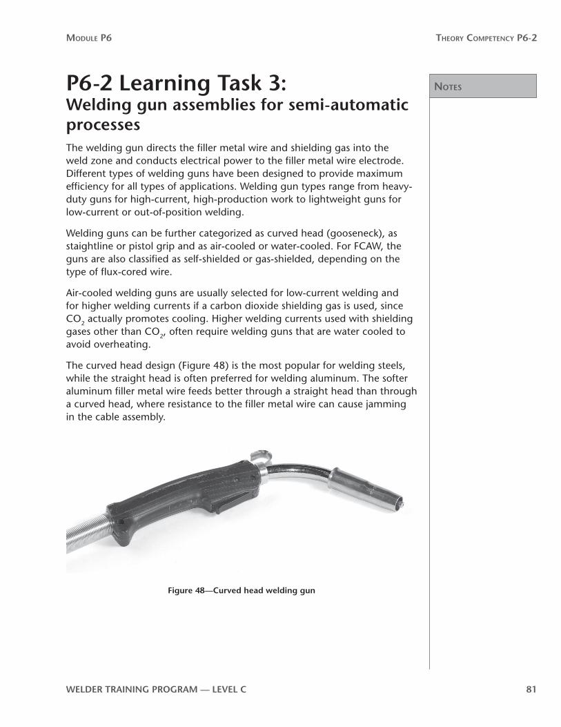
noTes
Module P6 Theory CoMPeTenCy P6-2
WelDer TrAInInG PrOGrAM — level C 81
P6-2 learning Task 3: Welding gun assemblies for semi-automatic processesThe welding gun directs the filler metal wire and shielding gas into the weld zone and conducts electrical power to the filler metal wire electrode. Different types of welding guns have been designed to provide maximum efficiency for all types of applications. Welding gun types range from heavy-duty guns for high-current, high-production work to lightweight guns for low-current or out-of-position welding.
Welding guns can be further categorized as curved head (gooseneck), as staightline or pistol grip and as air-cooled or water-cooled. For FCAW, the guns are also classified as self-shielded or gas-shielded, depending on the type of flux-cored wire.
Air-cooled welding guns are usually selected for low-current welding and for higher welding currents if a carbon dioxide shielding gas is used, since CO2 actually promotes cooling. Higher welding currents used with shielding gases other than CO2, often require welding guns that are water cooled to avoid overheating.
The curved head design (Figure 48) is the most popular for welding steels, while the straight head is often preferred for welding aluminum. The softer aluminum filler metal wire feeds better through a straight head than through a curved head, where resistance to the filler metal wire can cause jamming in the cable assembly.
Figure 48—Curved head welding gun
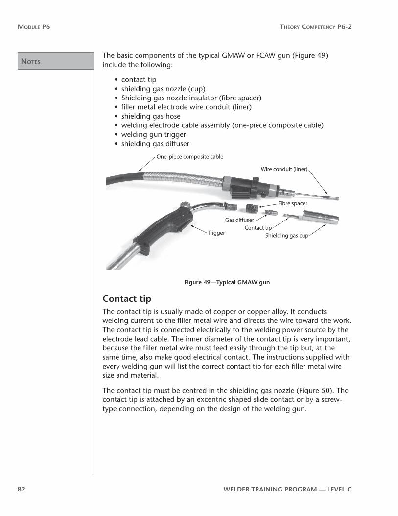
noTes
Module P6 Theory CoMPeTenCy P6-2
82 WelDer TrAInInG PrOGrAM — level C
The basic components of the typical GMAW or FCAW gun (Figure 49) include the following:
• contact tip• shielding gas nozzle (cup)• Shielding gas nozzle insulator (fibre spacer)• filler metal electrode wire conduit (liner)• shielding gas hose• welding electrode cable assembly (one-piece composite cable)• welding gun trigger• shielding gas diffuser
TriggerContact tip
Gas di�user
Shielding gas cup
Fibre spacer
Wire conduit (liner)
One-piece composite cable
Figure 49—Typical GMAW gun
Contact tipThe contact tip is usually made of copper or copper alloy. It conducts welding current to the filler metal wire and directs the wire toward the work. The contact tip is connected electrically to the welding power source by the electrode lead cable. The inner diameter of the contact tip is very important, because the filler metal wire must feed easily through the tip but, at the same time, also make good electrical contact. The instructions supplied with every welding gun will list the correct contact tip for each filler metal wire size and material.
The contact tip must be centred in the shielding gas nozzle (Figure 50). The contact tip is attached by an excentric shaped slide contact or by a screw-type connection, depending on the design of the welding gun.

noTes
Module P6 Theory CoMPeTenCy P6-2
WelDer TrAInInG PrOGrAM — level C 83
Electric cableGun tube
Insulator
Cable to contact tube adapter and gas di�user
Gas nozzle
Electrode
Electrode contact tip
Figure 50—Contact tip gas nozzle assembly
Contact tips become clogged or dirty easily. It is important that you check them frequently and replace them once this occurs.
Shielding gas nozzleThe shielding gas nozzle directs an even-flowing column of shielding gas into the welding zone. An even flow is extremely important in providing adequate protection of the molten weld pool from atmospheric contamination. Different size shielding gas nozzles are available and should be selected according to the application. Use larger nozzles for high welding current work where the weld pool is large. Use smaller shielding gas nozzles for low welding current and short-circuit metal transfer welding. The most common shielding gas nozzle material is copper. An electrical insulation or insulator on the inside provides electrical insulation from the electrically hot contact tip.
The filler metal wire exits through the contact tip, which is centred in the welding gun’s shielding gas nozzle (Figure 51).
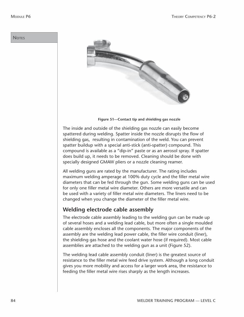
noTes
Module P6 Theory CoMPeTenCy P6-2
84 WelDer TrAInInG PrOGrAM — level C
Figure 51—Contact tip and shielding gas nozzle
The inside and outside of the shielding gas nozzle can easily become spattered during welding. Spatter inside the nozzle disrupts the flow of shielding gas, resulting in contamination of the weld. You can prevent spatter buildup with a special anti-stick (anti-spatter) compound. This compound is available as a “dip-in” paste or as an aerosol spray. If spatter does build up, it needs to be removed. Cleaning should be done with specially designed GMAW pliers or a nozzle cleaning reamer.
All welding guns are rated by the manufacturer. The rating includes maximum welding amperage at 100% duty cycle and the filler metal wire diameters that can be fed through the gun. Some welding guns can be used for only one filler metal wire diameter. Others are more versatile and can be used with a variety of filler metal wire diameters. The liners need to be changed when you change the diameter of the filler metal wire.
Welding electrode cable assemblyThe electrode cable assembly leading to the welding gun can be made up of several hoses and a welding lead cable, but more often a single moulded cable assembly encloses all the components. The major components of the assembly are the welding lead power cable, the filler wire conduit (liner), the shielding gas hose and the coolant water hose (if required). Most cable assemblies are attached to the welding gun as a unit (Figure 52).
The welding lead cable assembly conduit (liner) is the greatest source of resistance to the filler metal wire feed drive system. Although a long conduit gives you more mobility and access for a larger work area, the resistance to feeding the filler metal wire rises sharply as the length increases.

noTes
Module P6 Theory CoMPeTenCy P6-2
WelDer TrAInInG PrOGrAM — level C 85
Figure 52—Gun and cable assembly
Resistance against the filler metal wire results from the compressive force on the wire (which is greatest at the drive-unit end) and from friction (which rises proportionally with the length of the liner). Too much resistance can cause chattering and slippage at the wire feed drive rolls or buckling of the wire. Friction and compression work as resistance to smooth wire feeding (Figure 53).
Conduit (liner)
Point of resistance
Filler metal wirePoint of resistance
Figure 53—resistance to feeding filler metal wire
Accurate alignment of the filler metal wire feed system components near the wire feed drive rolls is essential to smooth wire feeding. Misaligned parts or loose liners can cause high stresses in the filler metal wire and abrade the wire, especially near the wire feed drive rolls. The liner must also provide continuous support for the filler metal wire from the wire feed drive rolls through to the contact tip in the welding gun, as any unsupported length (particularly near the drive rolls) can lead to buckling.

noTes
Module P6 Theory CoMPeTenCy P6-2
86 WelDer TrAInInG PrOGrAM — level C
The larger diameter filler metal wires in particular require the liner to be fairly stiff. Because of their strength and rigidity, these wires will not feed properly if there are sharp bends or curves in the welding electrode cable assembly.
To provide insulation from the hot weldment, the welding electrode cable assembly is covered with a high-quality rubber such as neoprene. Neoprene is used rather than plastic because it has both electrical insulation properties and superior heat resistance. Neoprene withstands being pulled over hot welded or flame-cut materials and also has good resistance to the solvents used to clean the liner.
Most welding electrode cable assemblies have quick disconnect couplers (Figure 54) so that you can quickly and easily hook up the cable assembly to connections on the wire feeder and welding gun.
Figure 54—Welding electrode cable quick disconnect coupler
Welding electrode cable assembly sizeSeveral types and lengths of welding electrode cable assemblies are available. Selection depends mainly on the welding current setting required (Figure 55).
Amperes Maximum Cable length Cable Size
200 4.6 m (15 ft.) No.1
300 4.6 m (15 ft.) No.2/0
400 4.6 m (15 ft.) No. 3/0
500 4.6 m (15 ft.) No. 4/0
600 4.6 m (15 ft.) No. 2-2/0
Figure 55—recommended cable sizes
Filler metal wire conduits (liners)The type of filler metal wire liner you use will depend on the type and diameter of the filler metal wire. Hardened steel liners are best suited for steel wires. The difference in hardness between the low-carbon steel filler metal wire being fed and the hardened steel liner provides the smoothest wire feed with the lowest friction. Plastic and nylon liners are best suited for the soft wires (such as aluminum), as the hardened steel liners will scratch these softer wires.

noTes
Module P6 Theory CoMPeTenCy P6-2
WelDer TrAInInG PrOGrAM — level C 87
In addition to choosing the correct type of liner for the type of filler metal wire, you must also choose a liner diameter that is suitable for the filler metal wire diameter. The manufacturer will specify the correct liner size in the operator’s guide supplied with the welding gun and cable assembly.
Preventive maintenanceWith the high wire feed speeds and high duty cycles characteristic of the GMAW, GMAW-P, MCAW and FCAW processes, you should clean the liner often. Residual lubricant on the filler metal wire, metal particles and shop dust will accumulate. The rule of thumb is to blow out the conduit with compressed air once per work shift or when you change the spool of filler metal wire.
Now complete Self-Test 3 and check your answers.

Answers
Module P6 Theory CoMPeTenCy P6-2
88 WelDer TrAInInG PrOGrAM — level C
Self-Test 3Choose the best answer for each of the following questions.
1. Match the components shown in Figure 56 with the correct terms listed below.
a. Welding gun trigger
b. one-piece composite cable
c. conduit (liner)
d. contact tip
e. sheilding gas nozzle
f. sheilding gas diffuser
25
6
4
3
1
Figure 56
2. The contact tip is usually made of
a. tungsten
b. nickel or nickel alloy
c. copper or copper alloy
d. porcelain
3. The main function of the contact tip is to
a. protect the filler metal wire from contamination
b. conduct welding power to the filler metal wire
c. supply shielding gas to the weld area
d. reduce the possibility of burnback

Answers
Module P6 Theory CoMPeTenCy P6-2
WelDer TrAInInG PrOGrAM — level C 89
4. The main function of the shielding gas nozzle is to
a. direct shielding gas to the weld area
b. advance the filler metal wire in the contact tip
c. provide electrical contact between the welding electrode lead cable and the filler metal wire
d. reduce the possibility of burnback
5. The correct inside diameter of the contact tip depends on the
a. type of shielding gas and the flowrate
b. size of the shielding gas nozzle
c. duty cycle maintained
d. diameter of the filler metal wire
6. The size of the shielding gas nozzle depends mainly on the
a. welding current level
b. diameter of the filler metal wire
c. type of shielding gas and flowrate
d. diameter of the contact tip
7. Which shielding gas has the most cooling effect on the welding gun?
a. argon
b. carbon dioxide
c. helium
d. oxygen
8. Water-cooled welding gun assemblies are used mainly for
a. light-duty welding at low amperages with CO2
b. FCAW pipe welding
c. short-circuit metal transfer on steel
d. welding at high amperages with mixed shielding gases
9. Which type of liners are generally used for steel filler metalwires?
a. low-carbon steel
b. hardened steel
c. aluminum
d. nylon or plastic

Answers
Module P6 Theory CoMPeTenCy P6-2
90 WelDer TrAInInG PrOGrAM — level C
10. Which type of liners are most often used for soft wires?
a. low-carbon steel
b. hardened steel
c. aluminum
d. nylon or plastic
11. As the length of the welding electrode cable assembly increases, there will be
a. increased resistance to filler metal wire feed drive system
b. a greater risk of contamination of the weld deposit
c. a reduction in friction and compressive forces
d. a decrease in filler metal wire-feed speed
12. The liner must be accurately aligned with the filler metal wire-feed unit and must
a. be covered with a plastic or nylon coating
b. provide continuous support for the filler metal wire
c. provide for continuous electrical contact between the filler metal wire and welding electrode power cable
d. be coated with powdered flux
now go to the Answer Key and check your answers

noTes
Module P6 Theory CoMPeTenCy P6-2
WelDer TrAInInG PrOGrAM — level C 91
P6-2 learning Task 4:Primary and secondary process variables for semi-automatic welding equipmentThe welding variables in GMAW, GMAW-P, MCAW and FCAW include all the parameters you can control for the entire welding process. It is essential that you understand the effect each variable has on the properties and characteristics of the weld in order for you to achieve optimal results. Welding variables for semi-automatic welding processes can be classified into three categories:
• pre-selected variables• primary adjustable variables• secondary adjustable variables
Pre-selected variablesPre-selected variables (sometimes called “process variables”) include the types of welding power source, wire-feed drive rolls, metal transfer, filler metal wire and shielding gas. The choice of these variables depends on the type of metal to be welded, the mechanical properties required, the welding position and the deposition rate required for a particular job.
Pre-selected variables provide a measure of overall or general control of the process, but the finer, more delicate controls fall into the primary and secondary categories.
equipment selectionThe welding power source, the type and size of the wire-feed drive rolls and other equipment components must meet the requirements of the application. GMAW-P, for example, requires an inverter type welding power source to operate most efficiently. The range of welding power output, the range of open-circuit voltage and the range of wire-feed speed must correspond to the weld joint design and to the filler metal wire size. You must also consider the accessories needed for the mode of metal transfer selected and any other special requirements.
Filler metal selectionThe filler metal must produce a deposit that is equal to or superior to the base metal in mechanical properties. The weld deposit must be sound and free of discontinuities. The diameter of the filler metal wire is based on the thickness of the base metal and on the welding position. The choices of filler metal type for GMAW-P are the same as for GMAW.
The filler metal wire diameter affects the depth of penetration and the deposition rate during welding. Generally, the smaller the diameter of the filler metal wire, the greater the penetration and rate of deposition. The high

noTes
Module P6 Theory CoMPeTenCy P6-2
92 WelDer TrAInInG PrOGrAM — level C
current density of MCAW means that filler metal wires of a larger diameter still get good penetration.
When you are making preliminary decisions about the welding procedure as a whole, you should consider the effect of filler metal wire size on penetration and deposition. During the actual welding, you should change these parameters by adjusting the welding current or stickout.
Mode of filler metal transfer and shielding gasThe mode of filler metal transfer and the choice of shielding gas are interrelated. These variables have a very important affect on the weld bead profile, reinforcement, shape, penetration and spatter, which are important considerations in the design of the weldment. The gas requirements for GMAW-P in spray metal transfer mode are the same as for GMAW.
Primary adjustable variablesOnce the pre-selected variables are set, the primary adjustable variables can be determined. Primary adjustable variables control the formation of the weld bead by affecting penetration, bead width, bead height, deposition rate, arc stability and weld soundness. The primary variables include arc voltage (trim control for GMAW-P), welding current and, in automatic setups, travel speed and gun angle. They include those parameters that can be set to an assigned value and that can be accurately reset as the welding proceeds. Slope and inductance controls also fall into this category. The primary variables are very effective controls, as they can be measured very accurately and they can be adjusted continually during the welding process.
Welding currentThe amount of welding current that is delivered is determined by the setting at the wire-feed speed control. Each type and size of filler metal wire has a set current range within which you can operate to influence penetration, bead size and deposition rate.
The relationship between welding current and penetration is direct. For any change in welding current, there is a corresponding change in the depth of penetration. As the welding current increases, so does penetration. As welding current decreases, penetration also decreases.
The same relationship exists between welding current and the rate of filler metal deposition. The deposition rate is determined by the burn-off rate of the filler metal wire and the deposition efficiency of the welding process (the amount of filler metal wire that actually becomes part of the deposit). GMAW and MCAW tend to be very efficient in this regard.
The pulse programs in GMAW-P welding power sources are synergic. There are two controls to work with: wire-feed speed and trim (arc length). As wire-feed speed increases, the welding arc power level (peak amperage, background amperage, pulse width and pulse frequency) will also increase.
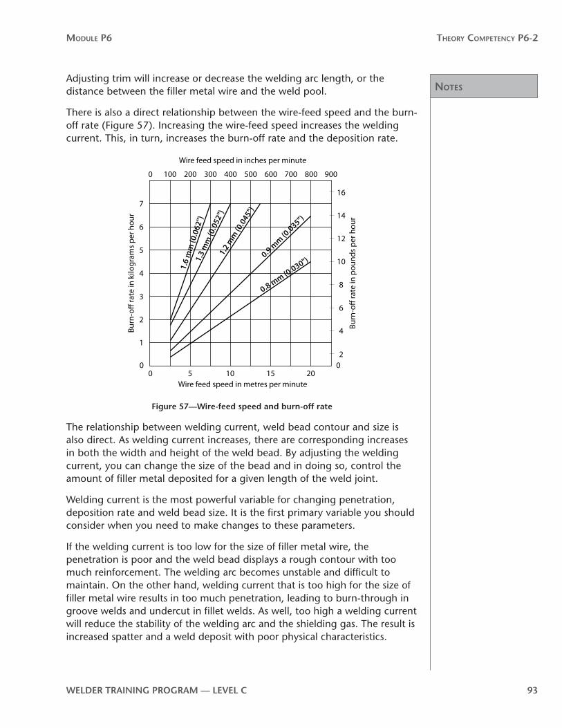
noTes
Module P6 Theory CoMPeTenCy P6-2
WelDer TrAInInG PrOGrAM — level C 93
Adjusting trim will increase or decrease the welding arc length, or the distance between the filler metal wire and the weld pool.
There is also a direct relationship between the wire-feed speed and the burn-off rate (Figure 57). Increasing the wire-feed speed increases the welding current. This, in turn, increases the burn-off rate and the deposition rate.
0
0 100 200 300 400 500 600 700 800 900
02
4
6
8
10
12
14
16
0
1
2
3
4
5
6
7
5 10 15 20Wire feed speed in metres per minute
Wire feed speed in inches per minute
Burn
-o�
rate
in p
ound
s pe
r hou
r
Burn
-o�
rate
in k
ilogr
ams
per h
our
1.6
mm
(0.0
62")
1.3
mm
(0.0
52")
1.2
mm
(0.0
45")
0.9 mm (0
.035")
0.8 mm (0.030")
Figure 57—Wire-feed speed and burn-off rate
The relationship between welding current, weld bead contour and size is also direct. As welding current increases, there are corresponding increases in both the width and height of the weld bead. By adjusting the welding current, you can change the size of the bead and in doing so, control the amount of filler metal deposited for a given length of the weld joint.
Welding current is the most powerful variable for changing penetration, deposition rate and weld bead size. It is the first primary variable you should consider when you need to make changes to these parameters.
If the welding current is too low for the size of filler metal wire, the penetration is poor and the weld bead displays a rough contour with too much reinforcement. The welding arc becomes unstable and difficult to maintain. On the other hand, welding current that is too high for the size of filler metal wire results in too much penetration, leading to burn-through in groove welds and undercut in fillet welds. As well, too high a welding current will reduce the stability of the welding arc and the shielding gas. The result is increased spatter and a weld deposit with poor physical characteristics.
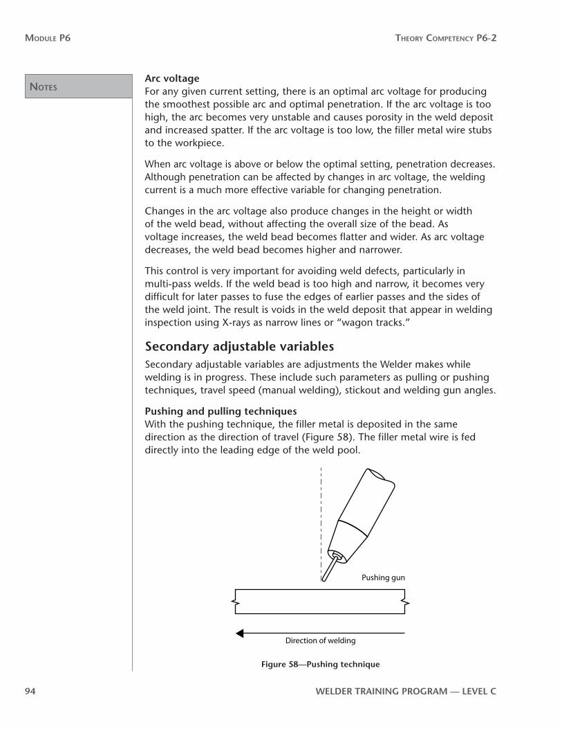
noTes
Module P6 Theory CoMPeTenCy P6-2
94 WelDer TrAInInG PrOGrAM — level C
Arc voltageFor any given current setting, there is an optimal arc voltage for producing the smoothest possible arc and optimal penetration. If the arc voltage is too high, the arc becomes very unstable and causes porosity in the weld deposit and increased spatter. If the arc voltage is too low, the filler metal wire stubs to the workpiece.
When arc voltage is above or below the optimal setting, penetration decreases. Although penetration can be affected by changes in arc voltage, the welding current is a much more effective variable for changing penetration.
Changes in the arc voltage also produce changes in the height or width of the weld bead, without affecting the overall size of the bead. As voltage increases, the weld bead becomes flatter and wider. As arc voltage decreases, the weld bead becomes higher and narrower.
This control is very important for avoiding weld defects, particularly in multi-pass welds. If the weld bead is too high and narrow, it becomes very difficult for later passes to fuse the edges of earlier passes and the sides of the weld joint. The result is voids in the weld deposit that appear in welding inspection using X-rays as narrow lines or “wagon tracks.”
Secondary adjustable variablesSecondary adjustable variables are adjustments the Welder makes while welding is in progress. These include such parameters as pulling or pushing techniques, travel speed (manual welding), stickout and welding gun angles.
Pushing and pulling techniquesWith the pushing technique, the filler metal is deposited in the same direction as the direction of travel (Figure 58). The filler metal wire is fed directly into the leading edge of the weld pool.
Direction of welding
Pushing gun
Figure 58—Pushing technique

noTes
Module P6 Theory CoMPeTenCy P6-2
WelDer TrAInInG PrOGrAM — level C 95
With the pulling technique, the filler metal is deposited in a direction opposite to the direction of travel (Figure 59). The filler metal wire is fed into the back of the weld pool towards the deposited weld bead.
Direction of welding
Pulling gun
Figure 59—Pulling technique
With the pulling technique, penetration is usually deeper because the welding arc tends to run into the weld pool and produce a greater concentration of heat. The force of the welding arc tends to push the molten filler metal towards the back of the weld pool to form a higher, narrower bead than that formed with a pushing technique.
With the pushing technique, the welding arc strikes relatively cold base metal at the front of the weld pool, so penetration tends to be shallower. The force of the welding arc tends to push the molten filler metal to the front and sides of the weld pool which forms a flatter weld bead contour than that formed with a pulling technique.
Travel speedThe travel speed is the rate at which the welding arc moves along the weld joint. It is usually expressed in metres or inches per minute. As the base metal thickness increases, the travel speed needs to be reduced. As welding current increases, the travel speed generally needs to increase. Higher travel speeds are possible with the pushing technique.
As a welding variable, travel speed has its most significant impact on the size of the weld bead. As travel speed decreases, the width and height of the weld bead both increase. Increased travel speeds, on the other hand, result in smaller weld beads in both width and height.
Along with welding current, travel speed becomes an important control for ensuring that joints are adequately filled in the desired number of passes. If a given travel speed and welding current are not providing enough weld
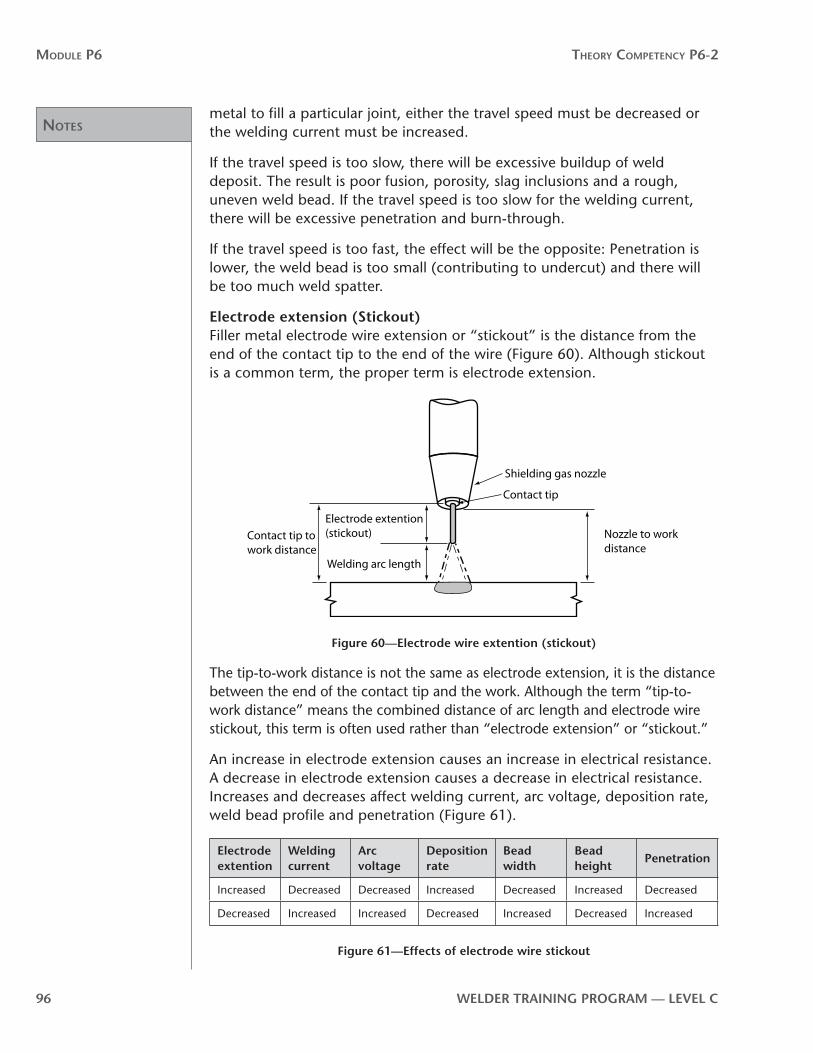
noTes
Module P6 Theory CoMPeTenCy P6-2
96 WelDer TrAInInG PrOGrAM — level C
metal to fill a particular joint, either the travel speed must be decreased or the welding current must be increased.
If the travel speed is too slow, there will be excessive buildup of weld deposit. The result is poor fusion, porosity, slag inclusions and a rough, uneven weld bead. If the travel speed is too slow for the welding current, there will be excessive penetration and burn-through.
If the travel speed is too fast, the effect will be the opposite: Penetration is lower, the weld bead is too small (contributing to undercut) and there will be too much weld spatter.
electrode extension (Stickout)Filler metal electrode wire extension or “stickout” is the distance from the end of the contact tip to the end of the wire (Figure 60). Although stickout is a common term, the proper term is electrode extension.
Shielding gas nozzle
Nozzle to work distance
Electrode extention (stickout)
Contact tip
Welding arc length
Contact tip to work distance
Figure 60—electrode wire extention (stickout)
The tip-to-work distance is not the same as electrode extension, it is the distance between the end of the contact tip and the work. Although the term “tip-to-work distance” means the combined distance of arc length and electrode wire stickout, this term is often used rather than “electrode extension” or “stickout.”
An increase in electrode extension causes an increase in electrical resistance. A decrease in electrode extension causes a decrease in electrical resistance. Increases and decreases affect welding current, arc voltage, deposition rate, weld bead profile and penetration (Figure 61).
electrode extention
Welding current
Arc voltage
Deposition rate
Bead width
Bead height
Penetration
Increased Decreased Decreased Increased Decreased Increased Decreased
Decreased Increased Increased Decreased Increased Decreased Increased
Figure 61—effects of electrode wire stickout

noTes
Module P6 Theory CoMPeTenCy P6-2
WelDer TrAInInG PrOGrAM — level C 97
During welding, you can adjust the electrode extension to make small changes in the depth of penetration and the weld bead profile.
Electrode extension usually ranges from 6 mm to 20 mm (1⁄4 in. to 3⁄4 in.) for GMAW. Longer stickouts, coupled with high wire-feed speeds, are often used for high-speed welding of thin gauge materials, as the welding current can be kept low and distortion will be minimized.
Stickout distances for MCAW in spray metal transfer mode are in the range of 16 mm to 19 mm (5⁄8 in. to ¾ in.) for all filler metal wire sizes, voltage settings and wire feed speeds.
For FCAW, the electrode extension ranges from 13 mm to 28 mm (1⁄2 in. to 11⁄2 in.) for gas-shielded filler metal wires and up to 95 mm (31⁄2 in.) for self-shielded filler metal wires. The correct stickout depends on filler metal wire diameter and type.
electrode angleThe filler metal electrode wire or nozzle angle is the position of the electrode wire with respect to the weld joint. There are two angles to consider: the work angle and the travel angle. The work angle is the filler metal electrode wire’s position with respect to the base metal (Figure 62A). The travel angle is the filler metal electrode wire’s position with respect to the length of the weld joint (Figure 62B).
Work angle
A. End view B. Side view
Travel angle
Figure 62—Filler metal electrode wire angles
Generally, the work angle is half of the angle formed by the weld joint. Normally, the work angle for fillet welds is 45° which is the mid point between the surface of the pieces being joined (Figure 62A). For groove welds the work angle is also half of the angle formed by the weld joint. However, this tends to always be 90° from the surface of the pieces being joined, especially for the root weld bead. For subsequent weld passes on both fillet welds and groove welds, the angle can vary a few degrees to allow for proper wetting of the weld pool to the edges of the weld joint.

noTes
Module P6 Theory CoMPeTenCy P6-2
98 WelDer TrAInInG PrOGrAM — level C
The travel angle generally ranges from 5° to 15° for both fillet and groove welds.
Summary of welding variablesAdjustments of the welding variables work together to produce desired changes in the weld deposit. You must make these adjustment in the correct sequence (Figure 63).
Welding variable
required Change
Arc voltage
Welding Current
Travel Speed
electrode Angle
electrode extension
Filler Wire Size
Shielding Gas Type
Deeper Penetration
1 Increase
3 Pulling Max 25°
2 Decrease
5 Smaller
4 CO2
Shallower Penetration
1 Decrease
3 Pushing 2 Increase 5 Larger
4 Ar + CO2
Higher Wider Weld Bead
1 Increase
1 Decrease
3 Increase
Flatter Narrower Weld Bead
1 Decrease
1 Increase
3 Decrease
Higher Narrower Weld Bead
2 Pulling 3 Increase
Flatter Wider Weld Bead
1 Increase
2 90° or Pushing
3 Decrease
Higher Deposition Rate
1 Decrease
1 Increase
2 Increase 3 Smaller
Lower Deposition Rate
1 Decrease
2 Decrease
3 Larger
Key: 1 = first choice, 2 = second choice, 3 = third choice, 4 = fourth choice, 5 = fifth choice
Figure 63—Welding variables
Now complete Self-Test 4 and check your answers.

noTes
Module P6 Theory CoMPeTenCy P6-2
WelDer TrAInInG PrOGrAM — level C 99

Answers
Module P6 Theory CoMPeTenCy P6-2
100 WelDer TrAInInG PrOGrAM — level C
Self-Test 4Choose the best answer for each of the following questions.
1. Which of the following results when welding current is increased?
a. increased penetration
b. decreased penetration
c. increased electrode extension
d. decreased electrode extension
2. Generally, the smaller the diameter of the filler metal wire,
a. the shallower the depth of penetration
b. the greater the depth of penetration
c. the wider the weld bead
d. the higher the weld bead
3. Which of the following is an effect of increasing filler metal wire-feed speed?
a. reduced penetration
b. increased arc voltage
c. smaller weld bead size
d. higher deposition rate
4. As arc voltage increases, the weld bead becomes
a. larger overall
b. flatter and wider
c. higher and narrower
d. smaller overall
5. As filler metal wire-feed speed increases, the weld bead becomes
a. larger overall
b. flatter and wider
c. higher and narrower
d. smaller overall

Answers
Module P6 Theory CoMPeTenCy P6-2
WelDer TrAInInG PrOGrAM — level C 101
6. As travel speed increases, the weld bead becomes
a. larger overall
b. flatter and wider
c. higher and narrower
d. smaller overall
7. Which of the following is an effect of increased burn-off rates?
a. decreased wire-feed speed
b. increased deposition
c. decreased electrode extension
d. decreased bead size
8. Too high a welding current can lead to
a. shallow penetration
b. insufficient deposition
c. burn-through
d. difficulty in maintaining the welding arc
9. As a primary variable, arc voltage is important in adjusting the
a. size of the weld bead
b. shape of the weld bead
c. rate of deposition
d. filler metal wire-feed speed
10. Match the effect of increased stickout distance on the following:
a. welding current 1. increased
b. deposition rate 2. decreased
c. weld bead width
d. weld bead height
e. penetration
11. Match the technique with the weld characteristics listed below.
a. flatter, wider weld bead 1. pushing technique
b. higher, narrower weld bead 2. pulling technique
c. deeper penetration
d. shallower penetration

Answers
Module P6 Theory CoMPeTenCy P6-2
102 WelDer TrAInInG PrOGrAM — level C
12. The drawing in Figure 64 shows the
a. pushing technique
b. pulling technique
Direction of welding
Figure 64
now go to the Answer Key and check your answers
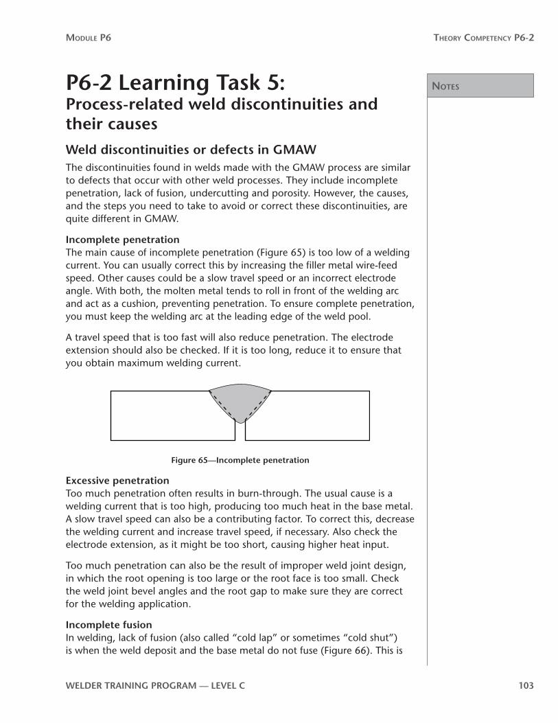
noTes
Module P6 Theory CoMPeTenCy P6-2
WelDer TrAInInG PrOGrAM — level C 103
P6-2 learning Task 5:Process-related weld discontinuities and their causesWeld discontinuities or defects in GMAWThe discontinuities found in welds made with the GMAW process are similar to defects that occur with other weld processes. They include incomplete penetration, lack of fusion, undercutting and porosity. However, the causes, and the steps you need to take to avoid or correct these discontinuities, are quite different in GMAW.
Incomplete penetrationThe main cause of incomplete penetration (Figure 65) is too low of a welding current. You can usually correct this by increasing the filler metal wire-feed speed. Other causes could be a slow travel speed or an incorrect electrode angle. With both, the molten metal tends to roll in front of the welding arc and act as a cushion, preventing penetration. To ensure complete penetration, you must keep the welding arc at the leading edge of the weld pool.
A travel speed that is too fast will also reduce penetration. The electrode extension should also be checked. If it is too long, reduce it to ensure that you obtain maximum welding current.
Root opening too small
Included angle too small
Root face too largeFigure 65—Incomplete penetration
excessive penetrationToo much penetration often results in burn-through. The usual cause is a welding current that is too high, producing too much heat in the base metal. A slow travel speed can also be a contributing factor. To correct this, decrease the welding current and increase travel speed, if necessary. Also check the electrode extension, as it might be too short, causing higher heat input.
Too much penetration can also be the result of improper weld joint design, in which the root opening is too large or the root face is too small. Check the weld joint bevel angles and the root gap to make sure they are correct for the welding application.
Incomplete fusionIn welding, lack of fusion (also called “cold lap” or sometimes “cold shut”) is when the weld deposit and the base metal do not fuse (Figure 66). This is

noTes
Module P6 Theory CoMPeTenCy P6-2
104 WelDer TrAInInG PrOGrAM — level C
largely the result of poor welding technique, travel speed that is either too slow or too fast, or improper weld joint design. Keep the wire at the leading edge of the weld pool and maintain sufficient travel speed so the weld pool is not permitted to roll in front of the welding arc. Be sure that your travel speed allows enough heat to be generated to substantially melt the base metal.
Figure 66—Incomplete fusion
Cold lap can be a particular problem on a very wide weld joint. Because the welding arc is directed down the centre of the weld joint, the molten weld metal will flow and only cast against the side walls of the weld joint without melting them. When you weld thicker materials, whenever possible use a split weld bead technique after the root pass. Be sure to avoid large weld beads that bridge the entire weld joint.
Other factors that can also be responsible for poor fusion include low arc voltage (which prevents adequate weld pool wetting) and too much rust or mill scale on the base metal.
UndercutUndercutting appears as a groove in the base metal directly along the edges of the weld bead (Figure 67). This condition is usually the result of incorrect welding parameters, especially travel speed or arc voltage.
Figure 67—Undercut

noTes
Module P6 Theory CoMPeTenCy P6-2
WelDer TrAInInG PrOGrAM — level C 105
Arc voltage that is too high or too low can cause undercutting. When arc voltage is too low, the weld bead is too narrow and wetting at the edges of the weld deposit is inadequate. When arc voltage is too high, the weld bead is wider, but not enough heat is supplied to the weld zone and the outermost areas cool very quickly, which again prevents proper wetting.
When travel speed is too high, solidification of the weld pool is very rapid and surface tension draws the weld metal toward the centre of the bead, leaving a groove where the weld metal meets the base metal.
Too high of welding currents can also contribute to undercutting, because the welding arc heat and penetration are so great that base metal is “blown” away. The weld pool becomes turbulent and prevents proper wetting at the outer edges of the deposit.
voidsVoids are caused by wagon tracks and valleys. Wagon tracks and valleys are a form of undercut that occurs along the sides of the weld deposit (Figure 68). When a weld bead is too convex, the next weld bead cannot completely fill the area between the earlier weld bead and the base metal, leaving voids in the weld deposit. Adjusting the arc voltage to produce flatter weld beads and improved melting at the sides of the bead usually corrects the problem.
Voids Voids
Figure 68—voids
Porosity“Porosity” means that there are gas pockets trapped in the solidified weld deposit (Figure 69). The main cause of porosity is atmospheric contamination that occurs when the supply of shielding gas is too high or too low. If the shielding gas flowrate is too low, the gas is unable to displace all the atmospheric air in the welding arc area. If the shielding gas flowrate is too high, atmospheric air is drawn into the gas stream, reducing the effectiveness of the gas shield. Improper welding techniques, such as too much electrode extension and incorrect electrode angles, also create arc turbulence and insufficient shielding of the welding arc.
Figure 69—Porosity

noTes
Module P6 Theory CoMPeTenCy P6-2
106 WelDer TrAInInG PrOGrAM — level C
In windy or drafty areas, the shielding gas can be blown away from the welding arc. Protect the weld area with windbreaks. In some cases, increased shielding gas flowrates can also help. Defects in the shielding gas supply system such as clogged gas nozzles, damaged hoses or defective valves will also reduce the gas shield. It is also important that the filler metal wire is centred in the shielding gas flow. If it is off-centre, the welding arc becomes erratic and porosity could result.
The filler metal wire can contribute to porosity if it is the wrong type or it is damp or dirty. Too much lubricant on the filler metal wire introduces hydrocarbons, a source of hydrogen, which is a prime cause of porosity.
Base metal that is dirty, rusted, painted or greasy can also be a major contributing factor in creating porosity.
CrackingTwo types of cracking that tend to occur with GMAW are hot cracking and cold cracking. Hot cracking occurs while the weld pool is still “mushy.” It usually results from using an incorrect filler metal wire. Hot cracking occurs most often with stainless steel or aluminum, rather than low-carbon steel.
Cold cracking occurs after the weld pool has completely solidified. It is almost always associated with a weld bead that is too small to withstand the expansion and contraction stresses in the weld joint.
WhiskersWhiskers are short lengths of filler metal wire that extend through the root side of the weld joint. Whiskers occur when the filler metal wire is pushed past the leading edge of the weld pool. This filler metal wire then protrudes through the weld joint and becomes welded to the root side of the weld deposit. To avoid this problem, reduce travel speed, increase stickout slightly or reduce the filler metal wire-feed speed.
Following is a typical troubleshooting guide to the possible causes of the most common weld defects found in GMAW (Figure 70).

noTes
Module P6 Theory CoMPeTenCy P6-2
WelDer TrAInInG PrOGrAM — level C 107
Fault or Defect Possible Causes
Porosity 1. Heavy oxide, scale on base metal
2. Shielding gas flowrate too high or too low
3. Electrode extension too long
4. Wrong electrode angle
5. Travel speed too fast
6. Filler metal wire off centre in the nozzle
7. Wrong filler metal wire
Lack of penetration 1. Welding current too low
2. Electrode extension too long
3. Weld pool rolling in front of the welding arc
4. Weld joint design incorrect
Lack of fusion 1. Arc voltage and/or welding current too low
2. Wrong polarity
3. Travel speed too slow
4. Weld bead too convex
5. Too much oxide on base metal
Undercutting 1. Too little wetting at edge of weld bead
2. Arc voltage too high
3. Welding current too high
Too much penetration 1. Welding current too high
2. Travel speed too slow
3. Weld joint design incorrect
Too much spatter 1. Shielding gas flowrate too high
2. Arc voltage too high
3. Wrong filler metal
Figure 70—Troubleshooting guide
Dimensional discontinuitiesTwo types of dimensional discontinuities tend to occur with GMAW: incorrect weld bead size and insufficient throat/underfill.
Incorrect weld bead size is often the result of too slow or too fast a travel speed. Too slow a travel speed can cause the weld bead to be oversized. An oversized weld bead can result in lack of fusion and too much heat input into the base metal, causing distortion. The weldment might then be rejected for not meeting weld specifications, and you might have to rework it. Weld beads that are dimensionally oversized are also very costly.
A travel speed that is too fast can mean that the weld bead will be undersized. This can lead to weld failure if the weld bead is too small to handle the load and stresses applied to it.

noTes
Module P6 Theory CoMPeTenCy P6-2
108 WelDer TrAInInG PrOGrAM — level C
Underfill happens when not enough weld reinforcement is used to bring the cap of the weld deposit above the level of the weld joint.
Troubleshooting equipment and process problemsThe following table lists some of the common problems that occur in the GMAW process and their possible causes (Figure 71).
Problem Possible Cause
Erratic or too little shielding gas flowrate
1. Flowmeter cracked or broken
2. Gas supply hose connections loose
3. Leaks in gas supply hose
4. Freezing of carbon dioxide regulator/flowmeter
5. Flowrates too low
Filler metal wire stubs into weld pool
1. Arc voltage too low
2. Wire-feed speed too high
3. Too much (steep) slope
Too much spatter 1. Arc voltage too high
2. Too little (flat) slope
3. Wrong filler metal wire
Filler metal wire feeder stops feeding wire while welding
1. Control circuit breaker tripped or fuse blown
2. Control relay defective
3. Wire feed drive roll pressure too low
4. Filler metal wire spool spindle friction too great
5. Wire feed drive rolls worn; slipping
6. Wire feed drive motor burned out
7. Welding gun trigger switch defective or wire leads broken
8. Burnback of filler metal wire to contact tip
9. Circuit breaker tripped or fuse blown in welding power source (also source of current for wire feeder)
10. Primary power protective circuit breaker tripped or fuse blown
Filler metal wire feeds but is not energized. No welding arc.
1. Welding current contactor relay defective
2. Contactor control leads broken or not plugged in tightly
3. Welding current remote-standard switch defective or in wrong position
4. No welding ground lead connection
Erratic or unstable welding arc
1. Arc voltage too high
2. Too little (flat) slope
3. Shielding gas flowrate too high
4. Shielding gas flowrate too low
Burnback 1. Filler metal wire-feed speed too low
2. Arc voltage too high
3. Faulty contact tip
4. Faulty or dirty filler metal wire conduit (liner)
Figure 71—Troubleshooting process and equipment problems

noTes
Module P6 Theory CoMPeTenCy P6-2
WelDer TrAInInG PrOGrAM — level C 109
When troubleshooting problems are equipment-related, you must always follow the equipment manufacturer’s recommendations and repair procedures.
Now complete Self-Test 5 and check your answers.

Answers
Module P6 Theory CoMPeTenCy P6-2
110 WelDer TrAInInG PrOGrAM — level C
Self-Test 5Choose the best answer for each of the following questions.
1. Which of the following is the main cause of incomplete penetration?
a. welding current too high
b. welding current too low
c. arc voltage too high
d. arc voltage too low
2. The first step in correcting undercutting is to make sure that
a. travel speed is not too fast
b. welding current is not too low
c. the base metal is not dirty
d. shielding gas flowrates are not too high
3. To prevent cold lap in multi-pass welds, you should
a. increase weld joint bevel angles to 45°
b. use a stringer bead technique to fill the weld joint
c. focus the welding arc directly on the centre of the weld joint
d. use a weave technique to fill the weld joint
4. The most common cause of porosity in weld deposits is
a. improper weld joint design
b. travel speed that is too fast or too slow
c. too little wetting of the weld bead
d. too low or too high a shielding gas flowrate
5. Cold cracking in welds beads is most often the result of
a. too low or too high a shielding gas flowrate
b. “whiskers” in the weld joint
c. a weld bead that is too small
d. too much rust or scale on the base metal

Answers
Module P6 Theory CoMPeTenCy P6-2
WelDer TrAInInG PrOGrAM — level C 111
6. Excessive penetration usually results from
a. welding current too high
b. travel speed too fast
c. too little electrode extension
d. damp or dirty filler metal wire
7. Which weld fault does Figure 72 show?
a. cold lap
b. incomplete penetration
c. undercut
d. porosity
8. Which weld fault does Figure 73 show?
a. cold lap
b. incomplete penetration
c. undercut
d. porosity
Figure 73
9. To fix the problem of whiskers in the weld bead, you should
a. reduce your travel speed
b. decrease electrode extension
c. increase filler metalwire-feed speed
d. decrease arc voltage
10. Which adjustment corrects the problem of wagon tracks in the weld deposit?
a. increase welding current
b. reduce welding current
c. increase arc voltage
d. reduce arc voltage
Figure 72

Answers
Module P6 Theory CoMPeTenCy P6-2
112 WelDer TrAInInG PrOGrAM — level C
11. Too much weld spatter is most often the result of
a. travel speeds too fast
b. welding current too low
c. too much slope
d. arc voltage too high
12. Which of the following can contribute to porosity in the weld deposit?
a. improper weld joint design
b. travel speed too fast
c. use of deoxidized filler metal wire
d. not enough electrode extension
now go to the Answer Key and check your answers

Theory CompeTenCy p6-3:Filler metal electrode wires and shielding for GMAW, MCAW, FCAW and SAW
p6
-3


WelDer TrAInInG PrOGrAM — level C 115
Module P6 Theory CoMPeTenCy P6-3
OutcomesSolid filler metal wires such as those used in the GMAW process have been developed for most weldable base metals. This is one reason the GMAW process is so widely used. Tubular filler metal wires used in the cored wire processes (FCAW, MCAW) have been developed mainly for plain carbon and stainless steels.
When you have completed the Learning Tasks in this Theory Competency, you should be able to describe the:
• construction and operation of GMAW, MCAW, FCAW and SAW filler metal wires
• packaging of GMAW, MCAW, FCAW and SAW filler metal wires
• CSA and AWS classification systems and specifications for GMAW, MCAW, FCAW and SAW low-carbon steel filler metal wires
• applications for the more commonly used GMAW, MCAW, FCAW and SAW low-carbon steel filler metal wires
• basic care, handling and storage procedures for GMAW, MCAW, FCAW and SAW filler metal wires
• shielding gases used in GMAW, MCAW and FCAW processes
• shielding gas equipment and setups for GMAW, MCAW and FCAW
evaluationWhen you have completed all the Theory Competencies in module P6, you will take a written test. You must score at least 70% on this test. The test will include questions that are based on the following material from Competency P6-3:
• the characteristics and applications of filler metal wires• the CSA and AWS classification and specifications for filler metal wires• basic care, handling and storage procedures for filler metals• the characteristics and applications of shielding gases
resourcesAll the resources you will require are contained in this Theory Competency.

116 WelDer TrAInInG PrOGrAM — level C

noTes
Module P6 Theory CoMPeTenCy P6-3
WelDer TrAInInG PrOGrAM — level C 117
P6-3 learning Task 1: low carbon steel filler metal electrode wire for GMAW, MCAW, FCAW and SAWOne of the most important things you must consider in GMAW, MCAW, FCAW and SAW is choosing the correct filler metal wire. The filler metal wire and the shielding gas and/or flux together determine the physical characteristics and the mechanical properties of the weld metal deposit. The main aim in choosing a filler metal wire is to match the properties of the base metal as precisely as possible. Secondary factors to consider are the type of equipment to be used, weld bead size, deposition rate, shielding gas and service requirements.
GMAW and SAW filler metal wires are solid wires. GMAW requires an external shielding gas. SAW requires an external granular shielding flux.
FCAW and MCAW filler metal wires are tubular wires. FCAW wire contains fluxing and shielding materials in the core, and may or may not require an external shielding gas. MCAW filler metal contains powdered metal and deoxidizers in the core and requires an external shielding gas (Figure 74).
Solid wire Tubular wire
Flux or powdered metal and deoxidizers
Figure 74—Solid and tubular filler metal wire
Filler metal wires are coiled and packaged on spools. They are distributed in specified unit weights. Standard spools are currently measured in kilograms or pounds. Some of the standard sizes are 5, 15, 20 and 25 kg (11, 33, 44 and 55 lb.). The weight depends on the size of the filler metal wire-feed system and the particular welding application. For high-production welding, the filler metal wire is packaged in drums.
The surface of the filler metal wire must be clean. Lubricants used during the wire drawing process are difficult to clean off. If they remain on the filler metal wire, problems can occur with arc stability, porosity and in some cases, cracking in or along the weld deposit. The standard for checking filler metal wire cleanliness is the white glove test. If the glove becomes soiled as you run the wire between your fingers, place a felt scrubber ahead of the wire feeder drive rolls.

noTes
Module P6 Theory CoMPeTenCy P6-3
118 WelDer TrAInInG PrOGrAM — level C
Some filler metal wire manufacturers copper-coat their solid filler metal wire to minimize the formation of surface oxides and to improve the wire’s electrical conductivity as it makes contact with the contact tip.
With copper-coated filler metal wire, always be sure to check for “flaking” of the copper coating as it travels through the wire feeder drive rolls. Flaking can occur if the wire feeder drive rolls are set too tight or if they are out of alignment. Some low-cost filler metal wires have a thick copper coating that will peel off even under normal feeding conditions. Too much flaking can clog up the liner and cause erratic filler metal wire feeding.
Classification of low-carbon steel filler metal wiresThe Canadian Standards Association (CSA) and the American Welding Society (AWS) have developed specifications for filler metal wires used with the low-carbon and high-strength, low-alloy steels. As in the case of the specifications for SMAW electrodes, the CSA bases its specifications on tensile strength in metric units (MPa) and the AWS on tensile strength in imperial units (psi).
Solid (GMAW) filler metal wiresThe filler metal specifications for low-carbon steel are found in the CSA Standard W48.8 and in the AWS Standard A5.18. The specifications for the commonly used filler metal wire ER49S-6 in the CSA Standard and ER7OS-6 in AWS Standard tell you all the essential information (Figure 75). Since solid filler metal wires can be used in all positions, neither Standard has a designation for the welding position.
ER 49S-6CSA
ER 70S-6AWS
Indicates electrode
Indicates electrode
Tensile strength 490 MPa
Tensile strength 70000 PSI
Deoxidizers and other additions in the wire
Deoxidizers and other additions in the wire
Indicates solid wire
Indicates solid wire
Figure 75—Specifications of a commonly used filler metal wire
The R that follows the E in the specification indicates that, when cut to length, the wire can also be used as filler rod in the gas tungsten arc welding process.

noTes
Module P6 Theory CoMPeTenCy P6-3
WelDer TrAInInG PrOGrAM — level C 119
Most filler wires for GMAW are available in a wide range of diameters from 0.5 mm (0.020 in.) up to 1.6 mm (1⁄16 in.).
Deoxidizers in GMAW filler metal wiresWhen carbon dioxide (CO2) is used as the shielding gas, it will lose its essentially inert characteristics when subjected to the high temperature of the welding arc and break down into carbon monoxide and oxygen. When this happens, about 20% to 30% of the shielding gas in the weld area becomes oxygen. To compensate for this oxidizing characteristic, the filler metal wire must contain deoxidizing agents. These agents combine with the oxygen and form harmless oxides that float to the surface of the weld pool.
The most common deoxidizers present in filler metal wiress used for gas metal arc welding of low-carbon steel are manganese, silicon, aluminum, titanium and vanadium. A typical solid filler metal wire can contain 1.20% manganese, 0.34% silicon and 0.66% aluminum.
The following briefly describes the characteristics of commonly used GMAW filler metal wires. Of these, the ER49S-3 (ER70S-3) and the ER49S-6 (ER70S-6) are the most widely used.
er49S-1 (er70S-1)This class of filler metal wire is not widely used. It contains the lowest amount of silicon and provides little deoxidization. These filler metal wires are generally used for applications where weld quality is not critical and lower costs are important. If high-quality weld deposits are required, these filler metal wires run under an argon or argon-mix shielding. Otherwise CO2 is the shielding gas used.
er49S-2 (er70S-2)This class of filler metal wire contains considerably more deoxidizing agents, up to 2% of a titanium, zirconium and aluminum combination as well as silicon and manganese. They are mainly designed to be used with an argon or argon-mix shield, but CO2 can also be used for short-circuit transfer. The powerful deoxidizing agents (aluminum, titanium and zirconium) make these filler metal wires a good choice for welding rusty or dirty surfaces. They are also often used for out-of-position welding using short circuit metal transfer.
er49S-3 (er70S-3)This class of filler metal wire is for low-carbon and high-strength, low-alloy (HSLA) steels. These filler metal wires are similar in composition to the ER49S-1 (ER70S-1) wires, but they contain greater amounts of the deoxidizing agents silicon and manganese. They can be used with an argon or argon-mix shield or with carbon dioxide. Like the ER49S-2 (ER70S-2), they are a good choice for out-of-position welding.

noTes
Module P6 Theory CoMPeTenCy P6-3
120 WelDer TrAInInG PrOGrAM — level C
er49S-4 (er70S-4)This class of filler metal wire has a slightly higher manganese and silicon content. It produces a weld deposit with higher tensile strength than the three classes described above. The shielding gas used is CO2. This filler metal wire is designed to use a slightly longer arc length and is used most often for welds requiring more deoxidization than that provided by the ER49S-3 (ER70S-3) filler metal wires.
er49S-5 (er70S-5)Like the ER49S-2 (ER70S-2), this filler metal wire contains the powerful deoxidizers aluminum, titanium and zirconium. It is used for tough welding conditions, such as rusty or dirty base metal or base metals containing higher carbon or sulphur content. It is used with carbon dioxide shielding gas in the globular metal transfer mode and is often chosen for welding heavier sections where good penetration can be a problem. This filler metal wire is not available in the smaller diameters.
er49S-6 (er70S-6)This class of filler metal wire has the highest combination of manganese and silicon. It is recommended for applications where good weld bead appearance and low spatter are requirements. The ER49S-6 (ER70S-6) produces weld deposits with excellent impact resistance and high mechanical properties, and is one of the most often used filler metal wires. The recommended shielding gas is either CO2 or an argon CO2 mixture. Welding in all positions is possible with short-circuit metal transfer and pulse spray metal transfer.
er49S-7 (er70S-7)This classification of filler metal wire, also used with a CO2 shielding gas, has a high manganese content, which provides good wetting action and a good weld bead appearance. The weld deposit also exhibits slightly higher mechanical properties.
er49S-G (er70S-G)This is a general classification for filler metal wires that are not included in the other classifications. Newly developed GMAW filler metal wires that may exceed standard specifications are often placed under this classification. An example of this is the 0.5% molybdenum small-diameter filler metal wire used for pipeline welding.
er55S-D2 (er80S-D2)This is a low-alloy filler metal wire containing between 0.40% and 0.60% molybdenum, recommended for welding low-alloy steels such as AISI 4130. It produces a weld deposit with a tensile strength of 552 MPa (80 000 psi).
Stainless steel filler metal wireThere are important differences between the way low-carbon steel filler metal wires and stainless steel filler metal wires are identified and classified.
noTes
Module P6 Theory CoMPeTenCy P6-3
WelDer TrAInInG PrOGrAM — level C 121
There are many stainless steel filler metal wires available, For this training we are only going to discuss ER309LSi which is a good general purpose electrode wire that is used throughout industry.
1 Refer to module P4-9 for specific safety precautions required when welding stainless steels.
er309lSi This is an austenitic stainless steel filler metal wire designed for joining stainless steels to carbon steels or low-alloy steels. For GMAW and GMAW-P, an argon-oxygen blend shielding gas is recommended.
Aluminum filler metal wiresThe CSA specifications for aluminum filler metal wires is covered in Section W47.2 and the AWS specifications are covered in Section A5.5.
Aluminum filler metalwires are classified by composition in much the same way as aluminum and aluminum alloys are classified.
Like stainless steel, aluminum produces a very hard oxide on its surface. This oxide must be removed before welding. This can be done chemically or mechanically. If cleaning mechanically, a hand held stainless steel wire brush or scraper should be used. Wire wheels on power tools should be avoided as this tends to force the oxides into the base material. A new layer of oxide forms quickly, so recleaning is often required if the work is not completed in a timely fashion.
The filler metal wires are supplied in sealed packages. When they are opened the contents must be protected from moisture, oils and dust. In this module, we will only discuss the two most commonly used aluminum filler metal wires.
er4043This aluminum filler metal wire contains about 5% silicon. It is recommended for welding 1050, 1100, 3003, 6063 and 6061 aluminum alloy base metals. It has a lower melting point than 5XXX series filler metals. Welders prefer ER4043 because of its favourable welding characteristics. ER4043 alloys are less sensitive to weld bead cracking with 6XXX series base metal alloys. It is suitable for sustained elevated temperature service above 65° C (150° F). For GMAW and GMAW-P, argon or an argon-helium mixture shielding gas is used.
er5356ER5356 is one of the most widely used aluminum filler metal wires. This general-purpose aluminum-magnesium filler metal wire is designed for welding 5052 aluminum alloy base metals. It is also recommended for 6063 and 6061 aluminum alloy base metals. For GMAW and GMAW-P, argon or an argon-helium mixture shielding gas is used.

noTes
Module P6 Theory CoMPeTenCy P6-3
122 WelDer TrAInInG PrOGrAM — level C
Flux-cored filler metal wiresThe CSA specifications for FCAW low-carbon steel filler metal wires are found in CSA Standard W48.5M. The AWS specifications for FCAW are covered in AWS A5.20 (Figure 76).
E 49 2 T - 9 -C H
Electrode
Electrode
Tubular wire
Tubular wire
Slag system, current polarity and shielding gas
Slag system, current polarity and shielding gas
Tensile strength 490 mPa
Tensile strength 70000 PSI
Welding positions1 = all2 = �at and horizontal �llets
Welding positions1 = all0 = �at and horizontal �llets
CSA
E 7 0 T - 9
AWS
Controlled hydrogen
Figure 76—FCAW filler metal wire specifications
The flux-cored filler metal wire classifications are very similar to the solid filler metal wire classifications, except when the letter T is used to designate that the filler metal wire is tubular. The welding position is also specified.
The AWS classification may contain additional letters and numbers. For example, the letters M or C following the slag system, current, polarity and shielding gas digit indicates the type of shielding gas. An M stands for mixed gas and a C indicates 100% Co2. The letter J indicates that the electrode meets the minimum impact requirements for the improved toughness test. An H followed by a 4, 8 or 16 indicates a low-hydrogen electrode with a maximum hydrogen limit of 4, 8 or 16 ml per 100 grams of deposited weld metal. Electrodes with low hydrogen limits are designed for welding crack-sensitive steels.

noTes
Module P6 Theory CoMPeTenCy P6-3
WelDer TrAInInG PrOGrAM — level C 123
There is no standard specifying the flux and slag-forming agents used in the core of the FCAW filler metal wire. Manufacturers design their own core materials using the main ingredients identified in the following chart (Figure 77). However, all filler metal wires must meet the CSA and AWS specifications for tensile strength and other mechanical properties.
Suffix Flux
T-1 Rutile
T-2 Rutile, extra metal powders
T-3 Fluorspar, rutile, aluminum
T-4 Fluorspar, aluminum
T-5 Lime, fluorides (basic)
T-6 Fluorspar, lime, rutile, aluminum
T-7 Fluorspar, aluminum
T-8 Fluorspar, aluminum
T-9 Rutile
T-10 Fluorspar, aluminum
T-11 Fluorspar, iron powder, aluminum
T-G Not defined
T-GS Not defined
Figure 77—Main ingredients in FCAW filler metal wires
Flux-cored filler metal wires are either self-shielded or gas-shielded. Self-shielded means the fluxing agents in the core protect the molten weld pool during solidification. Gas-shielded means an external shielding gas is required in addition to the fluxing agents. Some filler metal wires can be used with or without external shielding. There is usually some reduction in ductility, penetration and toughness with these filler metal wires if shielding gas is not used. Flux-cored filler metal wires are available in a wide range of diameters.
If an external shielding gas is required, the gas is usually CO2. Some flux-cored filler metal wires are designed to be used with a 75% Ar 25% CO2 mixture.
FCAW filler metal wire classificationsThe following are the main classifications of FCAW filler metal wires.
T-1This filler metal wire features a high deposition rate, stable arc and relatively little spatter. Gas-shielding with CO2 is required with these filler metal wires. They are suitable for welding in the flat and horizontal positions.

noTes
Module P6 Theory CoMPeTenCy P6-3
124 WelDer TrAInInG PrOGrAM — level C
T-2This classification of filler metal wire features a higher manganese content and can be used to weld steels that have not been carefully cleaned. These filler metal wires require a CO2 shielding gas.
T-3These filler metal wires are self-shielded and are designed mainly for welding sheet and light plate in the flat and horizontal positions in a single pass.
T-4These filler metal wires are self-shielded. They are designed for both single-pass and multi-pass welding. They have been one of the more commonly used filler metal wires.
T-5This class of filler metal wire can be used with or without external gas shielding. However, welds beads made with a CO2 shielding gas are higher quality than those made without external shielding gas. The T-5 filler metal wires are characterized by globular metal transfer, relatively shallow penetration, a slightly convex weld bead profile and a thin, easily removed slag. These filler metal wires are particularly good for high-impact applications, because the weld deposit has the highest impact resistance of all the flux-cored filler metal wires.
T-6These filler metal wires are very similar to the E49T-5 (E70T-5), but they are designed exclusively for use without an externally applied shielding gas. They are used for both single-pass and multi-pass welding and are specially designed to give good low-temperature impact values. In general, these filler metal wires are used with DCEP and are characterized by spray metal transfer.
T-7These filler metal wires are used without external gas shielding and may be used for single-pass and multi-pass welding in all positions. The weld deposit has good resistance to cracking and the slag is designed to desulpherize the weld metal. These filler metal wires are used with DCEN.
T-8This classification of self-shielded filler metal wire is designed for high-deposition, all position welding for structural fabrication, including those subject to seismic requirements. They are DCEN and can be used for single or multi-pass welding. These wires meet the requirements of good impact properties.
T-9This classification of filler metal wire shares similarities with the T-5 classification group in that the mode of metal transfer is globular. It requires an externally applied shielding gas. The filler metal wires can be used for both single-pass and multi-pass welding. The deposit is characterized by low
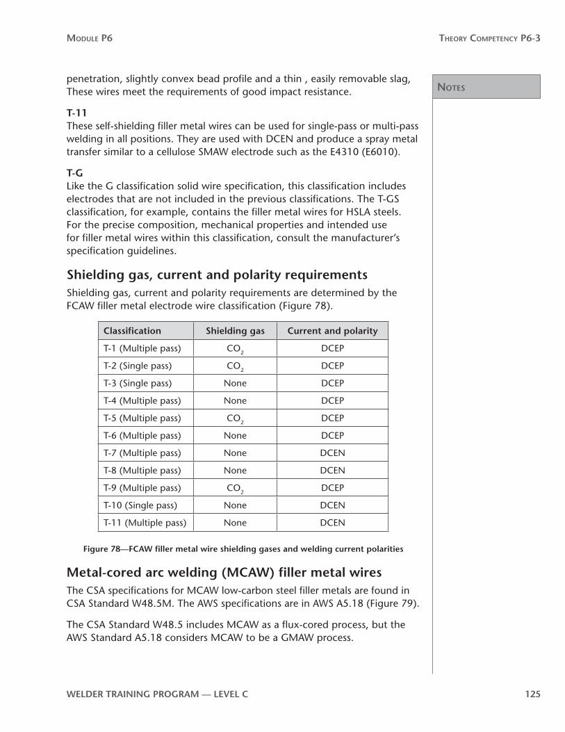
noTes
Module P6 Theory CoMPeTenCy P6-3
WelDer TrAInInG PrOGrAM — level C 125
penetration, slightly convex bead profile and a thin , easily removable slag, These wires meet the requirements of good impact resistance.
T-11These self-shielding filler metal wires can be used for single-pass or multi-pass welding in all positions. They are used with DCEN and produce a spray metal transfer similar to a cellulose SMAW electrode such as the E4310 (E6010).
T-GLike the G classification solid wire specification, this classification includes electrodes that are not included in the previous classifications. The T-GS classification, for example, contains the filler metal wires for HSLA steels. For the precise composition, mechanical properties and intended use for filler metal wires within this classification, consult the manufacturer’s specification guidelines.
Shielding gas, current and polarity requirementsShielding gas, current and polarity requirements are determined by the FCAW filler metal electrode wire classification (Figure 78).
Classification Shielding gas Current and polarity
T-1 (Multiple pass) CO2 DCEP
T-2 (Single pass) CO2 DCEP
T-3 (Single pass) None DCEP
T-4 (Multiple pass) None DCEP
T-5 (Multiple pass) CO2 DCEP
T-6 (Multiple pass) None DCEP
T-7 (Multiple pass) None DCEN
T-8 (Multiple pass) None DCEN
T-9 (Multiple pass) CO2 DCEP
T-10 (Single pass) None DCEN
T-11 (Multiple pass) None DCEN
Figure 78—FCAW filler metal wire shielding gases and welding current polarities
Metal-cored arc welding (MCAW) filler metal wiresThe CSA specifications for MCAW low-carbon steel filler metals are found in CSA Standard W48.5M. The AWS specifications are in AWS A5.18 (Figure 79).
The CSA Standard W48.5 includes MCAW as a flux-cored process, but the AWS Standard A5.18 considers MCAW to be a GMAW process.
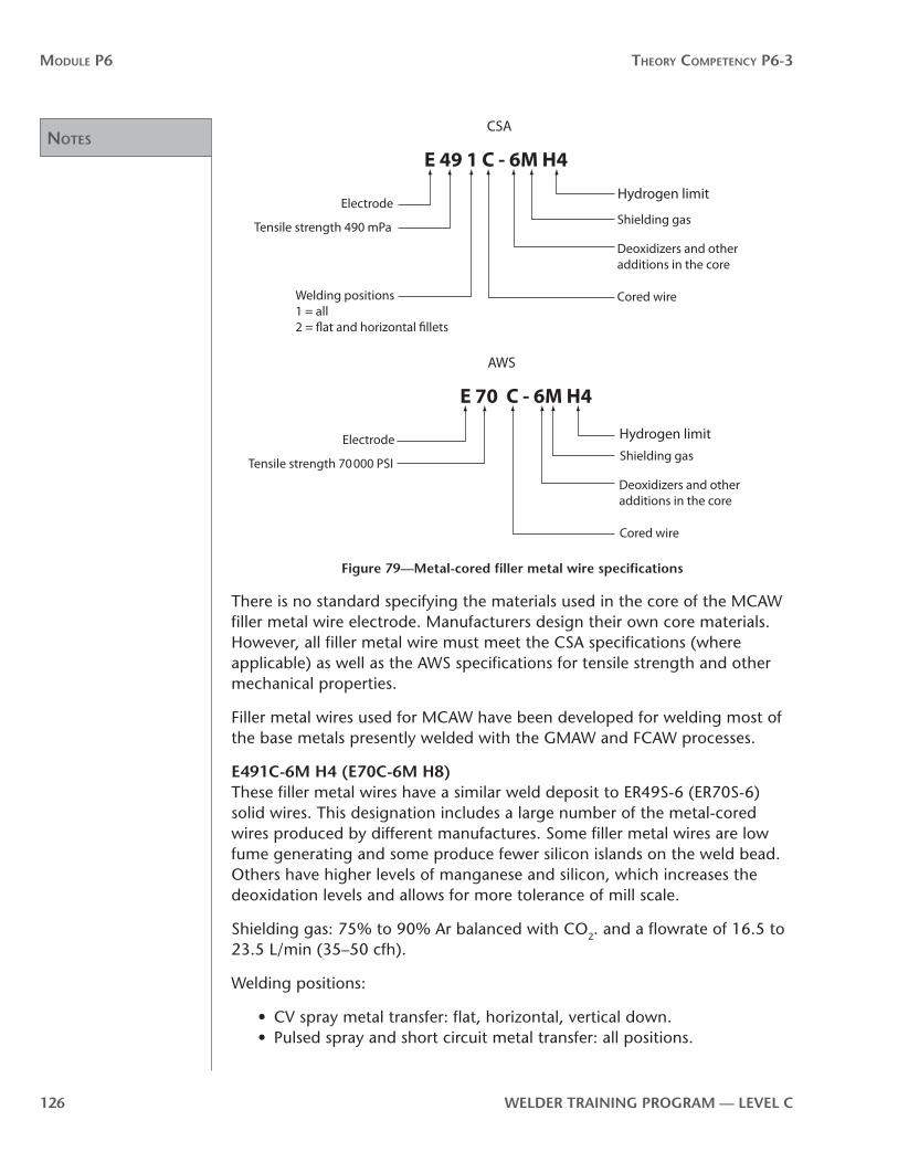
noTes
Module P6 Theory CoMPeTenCy P6-3
126 WelDer TrAInInG PrOGrAM — level C
E 49 1 C - 6M H4
Electrode
Electrode
Cored wire
Shielding gas
Shielding gas
Cored wire
Deoxidizers and other additions in the core
Deoxidizers and other additions in the core
Tensile strength 490 mPa
Tensile strength 70000 PSI
Welding positions1 = all2 = �at and horizontal �llets
CSA
E 70 C - 6M H4
AWS
Hydrogen limit
Hydrogen limit
Figure 79—Metal-cored filler metal wire specifications
There is no standard specifying the materials used in the core of the MCAW filler metal wire electrode. Manufacturers design their own core materials. However, all filler metal wire must meet the CSA specifications (where applicable) as well as the AWS specifications for tensile strength and other mechanical properties.
Filler metal wires used for MCAW have been developed for welding most of the base metals presently welded with the GMAW and FCAW processes.
e491C-6M H4 (e70C-6M H8)These filler metal wires have a similar weld deposit to ER49S-6 (ER70S-6) solid wires. This designation includes a large number of the metal-cored wires produced by different manufactures. Some filler metal wires are low fume generating and some produce fewer silicon islands on the weld bead. Others have higher levels of manganese and silicon, which increases the deoxidation levels and allows for more tolerance of mill scale.
Shielding gas: 75% to 90% Ar balanced with CO2. and a flowrate of 16.5 to 23.5 L/min (35–50 cfh).
Welding positions:
• CV spray metal transfer: flat, horizontal, vertical down.• Pulsed spray and short circuit metal transfer: all positions.
noTes
Module P6 Theory CoMPeTenCy P6-3
WelDer TrAInInG PrOGrAM — level C 127
(e80C-B2)This is a low-alloy metal-cored filler metal wire designed for single-pass or multi-pass welds on chrome-moly steels. E80C-B2 is used for welding castings and equipment.
Shielding gas: 98% Ar 2% CO2, or 75% Ar 25% CO2, with a flowrate of 16.5 to 23.5 L/min (35—50 cfh).
Welding positions:
• CV spray metal transfer: flat, horizontal, vertical down. • Pulsed spray and short circuit metal transfer: all positions.
(e90C-D2)This low-alloy metal-cored filler metal wire is equivalent to ER80S-D2 solid wire but offers better deposition rates. Developed for high-strength, low-alloy steels found in heavy equipment and structural parts.
Shielding gas: 98% Ar 2% O2, or 90% Ar 10% CO2, with a flowrate of 16.5 to 23.5 L/min (35–50 cfh).
Welding positions:
• CV spray metal transfer : flat, horizontal, vertical down. • Pulsed spray and short circuit metal transfer: all positions.
e80C-ni1 H8 (e80C-ni1)This low-alloy filler metal wire is designed for single-pass or multi-pass welds on nickel-molybdenum (Ni-Mo) steels such as ½ Ni-¼ Mo, 1 Ni-¼ Mo and 1½ Ni-¼ Mo. It is suited to welding castings and equipment and for applications requiring toughness at sub-zero temperatures.
Shielding gas: type is 98% Ar 2% O2, or 75% Ar 25% CO2, with a flowrate of 16.5 to 23.5 L/min (35–50 cfh).
Welding positions:
• CV spray metal transfer: flat, horizontal, vertical down. • Pulsed spray and short circuit metal transfer: all positions.
e80C ni1 H4 (e80C-ni1 H4)Similar to E80C-Ni1 H8 (E80C-Ni1), this low-alloy filler metal wire is suited to welding castings and equipment and for applications requiring toughness at sub-zero temperatures. It is also used to weld HSLA weathering steels in structural construction where colour match is not required.
Shielding gas: 98% Ar 2% O2, or 75% Ar 25% CO2, with a flowrate of 16.5 to 23.5 L/min (35–50 cfh).

noTes
Module P6 Theory CoMPeTenCy P6-3
128 WelDer TrAInInG PrOGrAM — level C
Welding positions:
• CV spray metal transfer: flat, horizontal, vertical down.• Pulsed spray and short circuit metal transfer: all positions.
e110C-G H4 (e110C-K4)This low-alloy filler metal wire is designed for single-pass and multi-pass welding of high-strength steels, including quenched and tempered high-strength steels such as A514(T1), HY80 and HY100. It can also be used for other high-strength applications such as welding castings, heavy equipment, and shipbuilding fabrication and repair.
Shielding gas: 75% Ar 25% CO2, or 90% Ar 10% CO2, with a flowrate of 16.5 to 23.5 L/min (35–50 cfh).
Welding positions:
• CV spray metal transfer: flat, horizontal, vertical down.• Pulsed spray and short circuit metal transfer: all positions.
Submerged Arc Welding (SAW) filler metal wires and fluxesFiller metal wires used for SAW are either solid or cored. Solid wires are more widely used. The most common ones range in diameter from 1.6 mm (1⁄16 in.) to 4.8 mm (3⁄16 in.), but they can go as large as 10 mm (3⁄8 in.) for extremely heavy applications.
SAW filler metal wires are classified on the basis of chemical composition (Figure 80). In this system, “E” indicates an electrode. The next letter (L, M or H) indicates low, medium or high manganese content in the filler metal wire. The following number or numbers indicate carbon content in hundredths of a percent. A suffix “K” indicates silicon-killed steel.

noTes
Module P6 Theory CoMPeTenCy P6-3
WelDer TrAInInG PrOGrAM — level C 129
AWS classification
Chemical composition, percent
Carbon Manganese Silicon Sulfur Phospherus CopperTotal other
elements
low manganese classes
0.035 0.03 0.15 0.50
EL8 0.10 0.30–0.55 0.05
EL8K 0.10 0.30–0.55 0.10–0.20
EL12 0.07–0.15 0.35–0.60 0.05
Medium manganese Classes
EM5Kb 0.06 0.90–1.40 0.40–0.70
EM12 0.07–0.15 0.85–1.25 0.05
EM12K 0.07–0.15 0.85–1.25 0.15–0.35
EM13K 0.07–0.19 0.90–1.40 0.45–0.70
EM15K 0.12–0.20 0.85–1.25 0.15–0.35
High manganese classes
EH14 0.10–0.18 1.75–2.25 0.05
Figure 80—AWS chemical composition requirements for submerged arc electrodes
There are three general classifications of SAW fluxes, active, neutral and alloy. Active fluxes contain controlled amounts of manganese and/or silicon. These alloys are added to the flux to provide improved resistance to porosity and weld cracking caused by contaminants on or within the base metal. They are useful when making single pass welds on scaled or rusty base metal. Neutral (basic) fluxes are those that will not produce any significant change in the weld deposit. Neutral fluxes give optimum strength and toughness in the weld deposit. Alloy fluxes include alloying elements such as chromium, nickel, molybdenum, columbium and manganese. This allows alloyed weld metal to be made with low-carbon steel electrodes.This happens as the flux is melted by the heat of the welding arc. This means that arc voltage control becomes very important because it determines the amount of flux being melted into the weld pool. The manufacture’s recommended voltage must be followed.
There are two basic types of SAW fluxes: bonded and fused. In bonded fluxes, finely ground chemicals are mixed, treated with a bonding agent and manufactured into a granular aggregate. Fused fluxes are a form of glass resulting from fusing the chemical mix and then grinding the glass to a granular form. Deoxidizers are incorporated into the fluxes.

noTes
Module P6 Theory CoMPeTenCy P6-3
130 WelDer TrAInInG PrOGrAM — level C
The fluxes used in SAW are classified based on the mechanical properties of the weld deposit made with a particular filler metal wire (Figure 81). The designation given to a flux consists of the prefix “F” (indicating flux) followed by a two-digit number representing the tensile strength and impact requirements for test welds made in accordance with the specification. This is then followed by a set of letters and numbers corresponding to the classification of the electrode used with the flux.
AWS classification flux-wire
Tensile strength ksi
Yield strength ksi min
elongation in 2 in % min
Temperature for 20 ft lbs
F6AX-EXXX 60–80 48 22 ††
F7AX-EXXX 70–95 58 22 ††
F8AX-EXXX 80–100 68 20 ††
F9AX-EXXX 90–110 78 17 ††
F10AX-EXXX 100–120 88 16 ††
F11AX-EXXX 110–130 98 15 ††
F12AX-EXXX 120–140 108 14 ††
†† The X in the first group of characters indicates the highest temperature at which an
impact strength of at least 20 ft. lbs. is obtained: 0 = 0ºF, 2 = –20ºF, 3 = –30ºF, 4 = –40ºF,
5 = –50ºF, 6 = –60ºF, 8 = –80ºF, 10 = –100ºF, 15 = –150ºF
Figure 81—AWS mechanical property requirements for submerged arc weld metal deposits
Storage requirements for SAW fluxes and filler metal wiresAny rust or hydrocarbon on SAW filler metal wires almost certainly means that there will be porosity in the weld deposit. It is very important that the filler metal wires be stored in a clean, dry area.
SAW fluxes must be kept dry to perform properly. Fluxes in their original unopened bags will remain dry if stored in a clean, dry, protected area. When open bags are exposed to the atmosphere for a few days, the flux can become contaminated by absorbing moisture. Even a little moisture can cause underbead cracking and internal porosity. To reclaim moisture contaminated flux, heat it to at least 260º C (500º F) and hold it at that temperature for at least two hours.

noTes
Module P6 Theory CoMPeTenCy P6-3
WelDer TrAInInG PrOGrAM — level C 131
Handling of fluxes and filler metal wiresRolls of SAW filler metal wire can be very heavy. Be very careful when handling the filler metal wire. Nicks, bends or flat spots in the wire can cause feeding problems. Partial rolls are often left on wire feeder units when not in use. Cover the filler metal wire to prevent shop dust or moisture from causing potential welding problems later on.
There is normally a lot of unused flux left after the SAW process. It is common practice to salvage this unused flux for later use. Some submerged arc systems have a vacuum attachment especially disigned for this purpose. Salvaged flux often has bits of slag and mill scale from the base metal in it. The salvaged flux should be cleaned before reusing. A screen is used to remove larger bits of slag, and a magnet is used to remove the mill scale.
Match consumables to welding processHundreds of combinations of flux and filler metal wires are possible. Users of the SAW process should therefore consult with suppliers before choosing a particular combination for a given application
Now complete Self-Test 1 and check your answers.
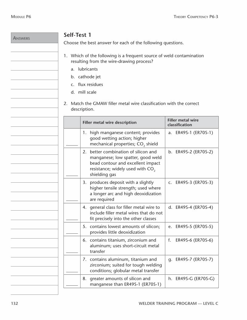
Answers
Module P6 Theory CoMPeTenCy P6-3
132 WelDer TrAInInG PrOGrAM — level C
Self-Test 1Choose the best answer for each of the following questions.
1. Which of the following is a frequent source of weld contamination resulting from the wire-drawing process?
a. lubricants
b. cathode jet
c. flux residues
d. mill scale
2. Match the GMAW filler metal wire classification with the correct description.
Filler metal wire description Filler metal wire classification
1. high manganese content; provides good wetting action; higher mechanical properties; CO2 shield
a. ER49S-1 (ER70S-1)
2. better combination of silicon and manganese; low spatter, good weld bead contour and excellent impact resistance; widely used with CO2 shielding gas
b. ER49S-2 (ER70S-2)
3. produces deposit with a slightly higher tensile strength; used where a longer arc and high deoxidization are required
c. ER49S-3 (ER70S-3)
4. general class for filler metal wire to include filler metal wires that do not fit precisely into the other classes
d. ER49S-4 (ER70S-4)
5. contains lowest amounts of silicon; provides little deoxidization
e. ER49S-5 (ER70S-5)
6. contains titanium, zirconium and aluminum; uses short-circuit metal transfer
f. ER49S-6 (ER70S-6)
7. contains aluminum, titanium and zirconium; suited for tough welding conditions; globular metal transfer
g. ER49S-7 (ER70S-7)
8. greater amounts of silicon and manganese than ER49S-1 (ER70S-1)
h. ER49S-G (ER70S-G)

Answers
Module P6 Theory CoMPeTenCy P6-3
WelDer TrAInInG PrOGrAM — level C 133
3. Which of the following filler metal wires contains molybdenum and is widely used for GMAW on low-alloy steels?
a. ER49S-B3
b. E492T-4
c. E552T-D2
d. ER55S-D2
4. Match the filler metal wire information with the correct letter shown on the filler metal wire specification in Figure 82.
a. deoxidizers and other elements
b. solid wire
c. electrode
d. tensile strength
ER 49S- 6
1 2 3 4
Figure 82
5. Deoxidizers in GMAW filler metal wires play a particularly important role when
a. CO2 shielding gas is used
b. argon shielding gas is used
c. helium shielding gas is used
d. neon shielding gas is used
6. In the specification for flux-cored wires, what does the letter “T” indicate?
a. tensile strength
b. toughness
c. tubular
d. titanium

Answers
Module P6 Theory CoMPeTenCy P6-3
134 WelDer TrAInInG PrOGrAM — level C
7. Match the correct filler metal wire classification with the description.
Filler metal wire description Filler metal wire classification
1. can be used with or without external shielding; globular transfer; highest impact resistance
a. T-11
2. gas-shielded; high deposition rate; relatively little spatter
b. T-9
3. gas-shielded; high manganese content; good for dirty steel
c. T-2
4. self-shielded; spray mode; single- and multi-pass welding in all positions
d. T-3
5. self-shielded; designed for sheet and light plate
e. T-1
6. gas-shielded; globular transfer; good impact resistance
f. T-5
8. Which shielding gas is normally used with flux-cored wires?
a. argon
b. carbon dioxide
c. helium
d. oxygen
9. Which of the following is true about the E491T-11 filler metal wire?
a. it has a tensile strength of 49 psi
b. it can be used for welding in all positions
c. it requires an externally applied gas shielding
d. its mode of metal transfer is globular
10. The suffix CH following a filler metal wire specification indicates controlled
a. carbon and hydrogen
b. hot shortness
c. heat input
d. hydrogen

Answers
Module P6 Theory CoMPeTenCy P6-3
WelDer TrAInInG PrOGrAM — level C 135
11. Indicate whether the following filler metal wires are gas-shielded or self-shielded.
a. E492T-1 (E70T-1)
b. E492T-2 (E70T-2)
c. E492T-3 (E70T-3)
d. E492T-4 (E70T-4)
e. E492T-5 (E70T-5)
f. E492T-6 (E70T-6)
g. E492T-7 (E71T-7)
h. E492T-9 (E71T-9)
i. E492T-11 (E4801T-11)
12. Which of the following classes of filler metal wires uses DCEN?
a. T-2
b. T-4
c. T-6
d. T-8
13. Which shielding gas is used with aluminun GMAW filler metal wires.
a. 100% Ar
b. 100% CO2
c. 75% Ar 25% CO2
d. 100% He
14. When classifying SAW filler metal wires the letters “L”, ”M” and ”H” stand for low, medium or high levels of in the wire.
a. silicon
b. chromium
c. manganese
d. graphite
now go to the Answer Key and check your answers

noTes
Module P6 Theory CoMPeTenCy P6-3
136 WelDer TrAInInG PrOGrAM — level C

noTes
Module P6 Theory CoMPeTenCy P6-3
WelDer TrAInInG PrOGrAM — level C 137
P6-3 learning Task 2:Shielding gases for GMAW and FCAWMost metals have a strong tendency to combine with oxygen to form oxides and (to a lesser extent) with nitrogen to form metal nitrides. Oxygen will also react with carbon to form carbon monoxide. These reactions occur readily, because the atmosphere is composed of about 78% nitrogen and 20% oxygen. A further source of contamination is from the hydrogen contained in the water vapour in the atmosphere. Very small amounts of these gases (if entrapped in the weld metal upon solidification) will lead to fusion defects, porosity and metal embrittlement.
The primary function of the shielding gas is to stop the surrounding atmosphere from coming in contact with the molten weld pool.
The shielding gas also has a large effect on the following aspects of the welding operation and the weld:
• arc characteristics• mode of metal transfer• weld bead penetration and profile• speed of welding• tendency toward undercutting• cleaning action
There are several types of shielding gases and shielding gas mixtures in general use with the GMAW, MCAW and FCAW processes. Some of the shielding gases have a broad range of application while others have very limited application.
Carbon dioxideCarbon dioxide (CO2) is a reactive rather than an inert gas. It is the only reactive gas suitable for shielding in GMAW. It is used only with carbon and low-alloy steels. Good welding speed, joint penetration and low cost have encouraged widespread use of CO2 as a shielding gas.
With a CO2 shield, the mode of metal transfer is either short-circuiting or globular. Spray metal transfer is possible only with an 80% argon shielding gas and cannot be achieved with pure CO2. The CO2 shielded welding arc produces a weld bead with excellent penetration (Figure 83), but the surface appearance is rough and there is much less cleaning action than with other shielding gases.
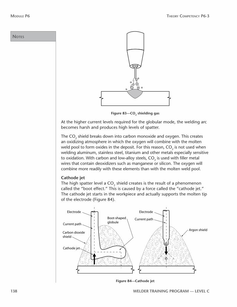
noTes
Module P6 Theory CoMPeTenCy P6-3
138 WelDer TrAInInG PrOGrAM — level C
Figure 83—CO2 shielding gas
At the higher current levels required for the globular mode, the welding arc becomes harsh and produces high levels of spatter.
The CO2 shield breaks down into carbon monoxide and oxygen. This creates an oxidizing atmosphere in which the oxygen will combine with the molten weld pool to form oxides in the deposit. For this reason, CO2 is not used when welding aluminum, stainless steel, titanium and other metals especially sensitive to oxidation. With carbon and low-alloy steels, CO2 is used with filler metal wires that contain deoxidizers such as manganese or silicon. The oxygen will combine more readily with these elements than with the molten weld pool.
Cathode jetThe high spatter level a CO2 shield creates is the result of a phenomenon called the “boot effect.” This is caused by a force called the “cathode jet.” The cathode jet starts in the workpiece and actually supports the molten tip of the electrode (Figure 84).
Current path
Electrode
Cathode jet
Current path
Carbon dioxide shield
Argon shield
Boot-shaped globule
Electrode
Figure 84—Cathode jet
noTes
Module P6 Theory CoMPeTenCy P6-3
WelDer TrAInInG PrOGrAM — level C 139
The molten ball can grow up to two or three times the diameter of the wire to form a boot-shaped globule that can interfere with the transfer of metal, destabilize the arc and produce high spatter levels.
The carbon dioxide used as a shielding gas must be of high purity and have a dew point below –40°C (–40°F). The CO2 cylinder must be marked “welding grade,” which indicates it has been tested to ensure that it meets the purity and dew point standards.
The dew point is the temperature at which water vapour will condense out of the gas onto a smooth, cold surface. The dew point is an indicator of the amount of moisture in gas. The lower the dew point, the less moisture the gas contains.
It is extremely important that moisture content in the CO2 be as low as possible, because even very small amounts will cause porosity in the weld deposit.
Argon and heliumArgon and helium are chemically inert gases, which means that they will not combine with the materials in the weld zone. These gases (and mixtures of the two) are required for welding non-ferrous metals. They are also widely used for stainless steel and low-alloy steels. The basic differences between argon and helium are density, thermal conductivity and the effect on welding arc characteristics.
DensityArgon is denser (heavier) than air, while helium is less dense (lighter) than air. This means that argon will sink in the atmosphere while helium will rise. In general, the heavier a shielding gas, the more effective it is for welding arc shielding. Helium being very light, rises and disperses rapidly. Shielding gas flowrates for helium need to be higher than for argon, particularly for welding in the flat or horizontal position. This makes helium more expensive to use.
Thermal conductivityHelium has a higher thermal conductivity than argon and also produces a welding arc plasma in which the arc energy is spread more evenly. The argon welding arc plasma is characterized by a very high-energy inner core and an outer mantle of lesser heat energy. This difference strongly affects the weld bead profile. The helium welding arc produces a deep, broad weld bead. The argon welding arc produces a weld bead profile most often characterized by a deep, narrow type penetration pattern (Figure 85) that is prone to lack of fusion at the sides of the weld bead.

noTes
Module P6 Theory CoMPeTenCy P6-3
140 WelDer TrAInInG PrOGrAM — level C
Argon Helium
Figure 85—Comparison of penetration and arc stability
The pure argon welding arc (and argon mixtures up to 85% argon) will produce spray transfer at current levels above the transition current. The helium shielded welding arc produces a more globular metal transfer in the normal operating range. The result is much higher levels of weld spatter and a rougher weld bead.
Ionization potentialThe argon shielded welding arc has a much lower ionization potential than helium, which means the argon arc plasma is produced at lower voltages. At any given current (wire-feed speed), the voltage of the argon welding arc is noticeably less than that of the helium welding arc. This means that for the argon welding arc a change in arc length will produce less change in the voltage. The argon welding arc is therefore more stable than the helium welding arc. The argon welding arc is also easier to start and has a better surface-cleaning action than a helium welding arc.
Pure argon shielding is used in many applications, especially for welding non-ferrous metals. It is also used in mixtures with other gases. Pure helium has very limited applications as a shielding gas for GMAW. Helium is almost always used in mixtures with other gases.
Shielding gas mixturesTo overcome some of the drawbacks of a particular shielding gas, mixtures have been developed using two, three and sometimes four different gases. The objective in using argon-helium mixes, for example, is to produce the weld bead profile obtained with helium, but still retain the stable welding arc characteristics of argon (Figure 86).

noTes
Module P6 Theory CoMPeTenCy P6-3
WelDer TrAInInG PrOGrAM — level C 141
Argon Helium HeliumArgon
Figure 86—Argon and helium compared to a argon-helium mixture
Argon-oxygen mixturesAdding small amounts of oxygen to argon improves welding arc stability and provides good wetting of the weld pool to the workpiece. The weld beads in Figure 87 show the effect of adding 5% oxygen to argon.
Weld metal
Base metal
95% Ar 5% O2 100% Ar
Figure 87—Comparison of Ar O2 mix with pure Ar
Mixtures of argon and oxygen are widely used for welding in the spray metal transfer mode on steel. Weld metal properties (especially toughness) are superior to those obtained with argon and carbon dioxide mixtures. Following are some common mixtures and their characteristics.
99% Ar 1% O2
This mixture is used mainly for welding in the spray metal transfer mode on stainless steel. The small amount of oxygen promotes welding arc stability and provides good weld bead appearance. It does not cause excessive oxidization of the weld surface.
98% Ar 2% O2
The increase to 2% oxygen improves wetting of the weld pool and the appearance of the weld bead. The main application for this mix is for welding low-alloy steels and, to some extent, stainless steels.

noTes
Module P6 Theory CoMPeTenCy P6-3
142 WelDer TrAInInG PrOGrAM — level C
95% Ar 5% O2
Argon mixtures with 3% to 5% oxygen are most often used for welding low-carbon steel in the spray metal transfer mode. Adding oxygen improves welding arc stability and weld bead contour, minimizes undercutting and permits faster travel speeds than pure argon.
Argon–carbon dioxide mixturesAdding CO2, rather than O2, gives greater penetration and higher welding speeds. The weld bead contour is similar to that obtained with an equivalent amount of oxygen. Spray metal transfer is still possible if the CO2 is kept to below 15%.
90% to 97% Ar 3% to 10% CO2
These mixtures are widely used in the spray metal transfer mode for low-carbon steel. This combination produces excellent penetration and reduces the possibilty of porosity that can be a problem when oxygen is added to argon. Weld pool wetting is comparable to the 5% O2 mixtures.
75% Ar 25% CO2
This mix is widely used in the short-circuit metal transfer mode on low-carbon steel. The increase in the CO2 content in argon produces increased penetration, while still maintaining the welding arc stability, low spatter and superior weld bead appearance characteristic of argon. This mix can be used in GMAW, MCAW and FCAW applications. Figure 88 compares the penetration and weld bead contour of a weld done in a pure CO2 shield and one done in a 75% Ar 25% CO2 shield. Where weld bead appearance is important and spatter is not tolerable, you should use this mixture rather than straight CO2.
Weld metal
Base metal
75% Ar 25% CO2 CO2
Figure 88—Comparison of 75% Ar 25% CO2 and pure CO2
85% Ar 15% CO2
This mixture is most commonly used for spray metal transfer welding of steel. It is used when high travel speeds (30% faster than pure CO2) and smooth weld bead appearance are wanted.
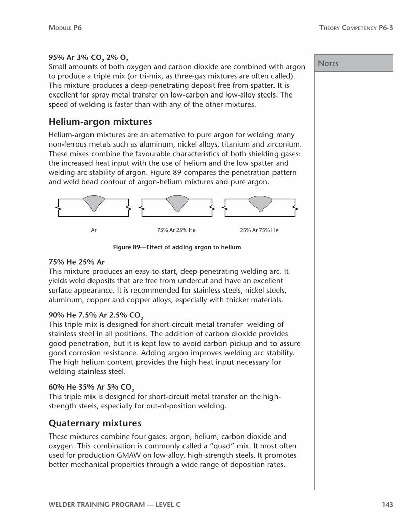
noTes
Module P6 Theory CoMPeTenCy P6-3
WelDer TrAInInG PrOGrAM — level C 143
95% Ar 3% CO2 2% O2
Small amounts of both oxygen and carbon dioxide are combined with argon to produce a triple mix (or tri-mix, as three-gas mixtures are often called). This mixture produces a deep-penetrating deposit free from spatter. It is excellent for spray metal transfer on low-carbon and low-alloy steels. The speed of welding is faster than with any of the other mixtures.
Helium-argon mixturesHelium-argon mixtures are an alternative to pure argon for welding many non-ferrous metals such as aluminum, nickel alloys, titanium and zirconium. These mixes combine the favourable characteristics of both shielding gases: the increased heat input with the use of helium and the low spatter and welding arc stability of argon. Figure 89 compares the penetration pattern and weld bead contour of argon-helium mixtures and pure argon.
Ar 75% Ar 25% He 25% Ar 75% He
Figure 89—effect of adding argon to helium
75% He 25% ArThis mixture produces an easy-to-start, deep-penetrating welding arc. It yields weld deposits that are free from undercut and have an excellent surface appearance. It is recommended for stainless steels, nickel steels, aluminum, copper and copper alloys, especially with thicker materials.
90% He 7 5% Ar 2 5% CO2
This triple mix is designed for short-circuit metal transfer welding of stainless steel in all positions. The addition of carbon dioxide provides good penetration, but it is kept low to avoid carbon pickup and to assure good corrosion resistance. Adding argon improves welding arc stability. The high helium content provides the high heat input necessary for welding stainless steel.
60% He 35% Ar 5% CO2
This triple mix is designed for short-circuit metal transfer on the high-strength steels, especially for out-of-position welding.
Quaternary mixturesThese mixtures combine four gases: argon, helium, carbon dioxide and oxygen. This combination is commonly called a “quad” mix. It most often used for production GMAW on low-alloy, high-strength steels. It promotes better mechanical properties through a wide range of deposition rates.
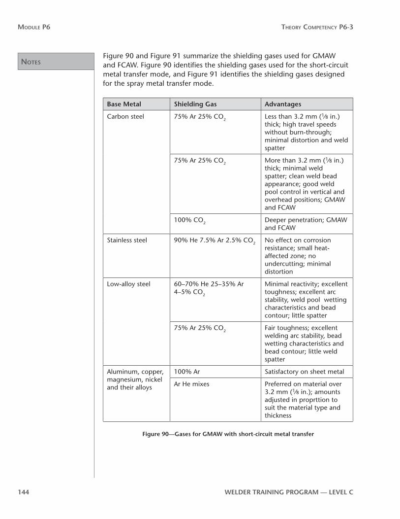
noTes
Module P6 Theory CoMPeTenCy P6-3
144 WelDer TrAInInG PrOGrAM — level C
Figure 90 and Figure 91 summarize the shielding gases used for GMAW and FCAW. Figure 90 identifies the shielding gases used for the short-circuit metal transfer mode, and Figure 91 identifies the shielding gases designed for the spray metal transfer mode.
Base Metal Shielding Gas Advantages
Carbon steel 75% Ar 25% CO2 Less than 3.2 mm (1⁄8 in.) thick; high travel speeds without burn-through; minimal distortion and weld spatter
75% Ar 25% CO2 More than 3.2 mm (1⁄8 in.) thick; minimal weld spatter; clean weld bead appearance; good weld pool control in vertical and overhead positions; GMAW and FCAW
100% CO2 Deeper penetration; GMAW and FCAW
Stainless steel 90% He 7.5% Ar 2.5% CO2 No effect on corrosion resistance; small heat-affected zone; no undercutting; minimal distortion
Low-alloy steel 60–70% He 25–35% Ar 4–5% CO2
Minimal reactivity; excellent toughness; excellent arc stability, weld pool wetting characteristics and bead contour; little spatter
75% Ar 25% CO2 Fair toughness; excellent welding arc stability, bead wetting characteristics and bead contour; little weld spatter
Aluminum, copper, magnesium, nickel and their alloys
100% Ar Satisfactory on sheet metal
Ar He mixes Preferred on material over 3.2 mm (1⁄8 in.); amounts adjusted in proprttion to suit the material type and thickness
Figure 90—Gases for GMAW with short-circuit metal transfer

noTes
Module P6 Theory CoMPeTenCy P6-3
WelDer TrAInInG PrOGrAM — level C 145
Base Metal Shielding Gas Advantages
Carbon steel 95–99% Ar 1–5% O2 Improved welding arc stability; more fluid and controllable weld pool; good fusion and weld bead contour; minimal undercutting; higher travel speeds than pure argon
90–97% Ar 3–10% CO2 Good weld bead contour; minimal weld spatter; reduced chance of coldlap; flat and horizontal positions only
Low-alloy steel 98% Ar 2% O2 Minimal undercutting; good toughness
Aluminum 100% Ar Up to 25 mm (1 in.) thick; best filler metal transfer and welding arc stability; least weld spatter
35% Ar 65% He Up to 25 mm (1 in.) thick; higher heat input than straight argon; improved weld pool fusion characteristics with 5XXX series Al-Mg alloys
25% Ar 75% He Over 75 mm (3 in.) thick; highest heat input; minimal porosity
Magnesium 100% Ar Excellent cleaning action
Stainless steel 99% Ar 1% O2 Improved welding arc stability; more fluid and controllable weld pool; good fusion and weld bead contour; minimal undercutting on heavier stainless steels
98% Ar 2% O2 Better welding arc stability, fusion and travel speed than 1% O2 mixture for thinner stainless steel materials
Copper, nickel and their alloys
100% Ar Good weld pool wetting; decreased fluidity of weld metal for thickness up to 3.2 mm (1⁄8 in.)
Ar He mixes Higher heat inputs of 50% and 75% He mixtures offset high heat dissipation of heavier gauge materials
Titanium 100% Ar Good welding arc stability; minimal weld pool contamination; inert gas backing is required to prevent air contamination on back of weld joint heat affected zone
Figure 91—Gases for GMAW with spray metal transfer

noTes
Module P6 Theory CoMPeTenCy P6-3
146 WelDer TrAInInG PrOGrAM — level C
Shielding-gas cylindersThe cylinders for the inert shielding gases used for GMAW are very similar in design and operation to those used for oxygen. They are high-pressure cylinders that can store gas at pressures up to 18 MPa (2600 psi) at 21º C (70º F). In response to increased consumption and the need for a longer lasting gas supply, cylinders have been designed for even higher pressures. Cylinders are now being built to store the gas at 31 MPa (4500 psi), which almost doubles the capacity of the cylinder. As a safeguard with these high pressures, the cylinder valve is protected by a heavy cast steel guard (Figure 92). To accommodate existing flowmeters and regulators, the cylinder valve is designed to deliver only 12 MPa (1800 psi).
Figure 92—Steel guard on high-pressure cylinder
CO2 cylindersCylinders used for carbon dioxide function slightly differently from high-pressure cylinders and have some unique problems. These cylinders are considered medium pressure, and at 21º C (70º F) the pressure is around 5.8 MPa (835 psi).
The commercial cylinders for welding-grade CO2 usually contain 23 kg (50 lb.) of CO2, of which about 20 kg (45 lb.) is in the liquid state and 3 kg (5 lb.) is a gas. In a full cylinder, the CO2 in liquid form occupies two-thirds of the cylinder and CO2 gas occupies the top third (Figure 93).

noTes
Module P6 Theory CoMPeTenCy P6-3
WelDer TrAInInG PrOGrAM — level C 147
The liquid CO2 absorbs heat through the walls of the cylinder and begins to boil or vaporize to a gas. As more gas is formed, the pressure in the cylinder rises. This in turn raises the boiling point of the liquid and vaporization stops. As the gas is drawn off for shielding, the pressure is reduced, the boiling point drops and vaporization resumes.
This cycle limits the rate of CO2 withdrawal, as it depends on heat absorption through the cylinder walls. Single cylinders are generally limited to 12–16 L/min (25–35 cfh). If heavier flowrates are required, two or more cylinders must be connected together with a manifold.
The pressure in the cylinder will be maintained until all the liquid CO2 has boiled or varporized, at this point the cylinder pressure begins to fall. A full cylinder of CO2 will last about 31⁄2 hours at a flowrate of 12 L/min (25 cfh) before all the gas is depleted. It is usually recommended that you change the cylinder when the pressures falls to 1030 kPa (150 psi).
CO2 pressure regulator “freeze-up”At flowrates greater than 12 L/min (25 cfh), CO2 pressure regulators become prone to freezing up. “Freeze-up” is caused by the expansion of the gas when it flows from a high-pressure inlet through an opening to a low-pressure outlet. When the gas hits the unheated low-pressure outlet of the pressure regulator, the cooling and subsequent condensation is so rapid that dry ice forms. This can freeze the pressure regulator and prevent it from functioning properly. The problem becomes more serious when shielding gas flowrates are high or the CO2 is warmer than the ambient temperature.
To combat this problem, you can use a heated pressure regulator or set up a manifold system in order to reduce the flowrate of each individual cylinder.
Shielding gas pressure regulatorsPressure regulators for CO2 and other inert shielding gases perform the same function as oxygen or acetylene pressure regulators. They reduce the high cylinder pressure down to a working pressure that can be used during welding. This can be done in one or two steps, with either a single-stage or a two-stage pressure regulator.
In general, single-stage pressure regulators are better for most manual welding jobs. Two-stage pressure regulators are better for precision welding and high-volume applications. On both types of pressure regulators, a
Liquid
Gas
Figure 93—A cylinder containing CO2

noTes
Module P6 Theory CoMPeTenCy P6-3
148 WelDer TrAInInG PrOGrAM — level C
pressure gauge shows the cylinder pressure. Most pressure regulators deliver a constant outlet pressure to the flowmeter of 345 kPa (50 psi).
If you find that the regulator needle creeps either up or down, it should be repaired.
FlowmetersThe amount of shielding gas around the welding arc can be measured by the volume of gas coming out of the shielding gas nozzle. The shielding gas system is equipped with a flowmeter that is calibrated in litres per minute (L/min) or cubic feet per hour (cfh). The flow of shielding gas can be adjusted by a control valve on the flowmeter. The calibrated scale on the inner tube is usually calibrated from 0 L/min to 28 L/min (0 cfh to 60 cfh). The flowmeter control valve is set by aligning the indicator ball with the L/min (cfh) reading desired (Figure 94).
Floating indicator ball
Gas out
Calibrated tube
Figure 94—Flowmeter
The rate of flow can be read at the top, bottom or centre of the floating indicator ball. It is common practice to read the flowrate at the centre.
noTes
Module P6 Theory CoMPeTenCy P6-3
WelDer TrAInInG PrOGrAM — level C 149
However, it is good practice to check the flowmeter manufacturer’s instructions to find out where to take the reading for their particular flowmeter.
For accurate reading, the flowmeter must be vertically aligned. If the flowmeter is tilted, the reading will not be accurate. Usually different flowmeters are required for the different shielding gases. This is because different shielding gases may require different scales of calibration. There are also universal flowmeters designed to measure several different gases. Universal flowmeters normally have a manufacturer’s reference chart with recommended calibrations for different shielding gases.
Gas mixersPremixed shielding gases for welding are readily available from most welding supply distributors. There are many mixtures that come premixed in cylinders. However, it is sometimes necessary to mix your own to get the precise combination you need. It is also generally less expensive to mix your own.
Each gas to be mixed is fed from its cylinder to individual flowmeters. You need to individually calculate the flowrate of each flowmeter to obtain the precise mixture you need. For example, to produce a mixture of 75% argon and 25% carbon dioxide at a flowrate of 18 L/min, you would make the following calculations to determine the individual flowmeter settings:
CO2
25100
75100
×
×
18L/min = 4.5/min
Ar 18L/min = 13.55L/min
The gases are fed from their individual flowmeters into a mixing chamber. The mixed gases are then fed through a final flowmeter to the welding gun.
Flowrates for shielding gasesFlowrates vary depending on the welding location (indoors or outdoors), the current setting, the shielding gas used, the mode of metal transfer and the speed of travel. As the current increases, the size of the weld pool increases and higher flowrates are needed to provide shielding. For short-circuit metal transfer on low-carbon steel, the shielding gas flowrates for either straight CO2 or a 75% Ar 25% CO2 mix vary between 12 and 16 L/min (25 and 35 cfh), depending on the material thickness and current level. For spray metal transfer requiring an argon or argon mix shield, the flowrates are in the 16 to 20 L/min (35 to 45 cfh) range. The specifications for a welding procedure will tell you the flowrate needed to provide adequate shielding of the weld area.

noTes
Module P6 Theory CoMPeTenCy P6-3
150 WelDer TrAInInG PrOGrAM — level C
Safe handling of shielding-gas equipment All gas cylinders must be labelled to identify the gases (or liquids)
they contain. The labels are usually placed near the cylinder valve. The outlet connections at the cylinder valve have special non-interchangeable fitting connections as specified by the Compressed Gas Association (CGA). The CGA outlet connections are number-coded in accordance with the type of gas and the size of the cylinder valve.
Always follow these safety precautions when you use shielding gases:
1. Read the WHMIS label on the cylinder or the MSD sheet.
2. Make sure the cylinder is adequately secured in the upright position.
3. Before connecting the pressure regulator to the cylinder valve, you should “crack” (slightly open and quickly close) the cylinder valve to clear out any dust or dirt in the valve.
Always stand to the side of the cylinder valve when cracking it and make sure it is not pointed at anyone else. Any particles inside the valve will fly out with great force.
4. On equipment that uses a conventional adjustable cylinder pressure regulator, make sure you release the pressure-adjusting screw by turning it counterclockwise before you open the cylinder valve. If a flowmeter is used, make sure the flowrate adjustment is at zero before you turn on the gas. Begin opening the cylinder valve slowly to prevent a rapid surge of high-pressure gas to the pressure regulator.
5. Close the cylinder valve when the cylinder is not in use.
6. Never try to repair faulty cylinder valves, regulators or flowmeters. They should be repaired by qualified technicians.
The high pressures in full cylinders means there is potential for explosion. They should be handled very carefully. They should never be dropped or allowed to bump against other cylinders or other objects. They should always be stored in the upright position away from heat sources such as radiators, heat vents or stoves. If stored outdoors they should be protected from direct sunlight.
Now complete Self-Test 2 and check your answers.

noTes
Module P6 Theory CoMPeTenCy P6-3
WelDer TrAInInG PrOGrAM — level C 151

Answers
Module P6 Theory CoMPeTenCy P6-3
152 WelDer TrAInInG PrOGrAM — level C
Self-Test 2Choose the best answer for each of the following questions.
1. Which of the following is an inert gas?
a. nitrogen
b. carbon dioxide
c. oxygen
d. argon
2. When used as a shielding gas, which of the gases listed below produces the weld bead contours in Figure 95?
a. oxygen
b. carbon dioxide
c. helium
d. argon
Argon Helium HeliumArgonFigure 95
3. Which of the following shielding gases produces the smoothest welding arc?
a. argon
b. carbon dioxide
c. helium
d. oxygen
4. Which of the following is characteristic of a carbon dioxide shielded welding arc?
a. a deep, narrow penetration pattern
b. a shallow, broad bead contour
c. high weld spatter levels
d. good surface cleaning action

Answers
Module P6 Theory CoMPeTenCy P6-3
WelDer TrAInInG PrOGrAM — level C 153
5. A shielding gas of 100% Ar is most widely used on
a. stainless steels
b. low-carbon steels
c. high-strength steels
d. non-ferrous metals
6. A shielding gas of 100% carbon dioxide is most widely used on
a. stainless steels
b. low-carbon steels
c. high-strength steels
d. non-ferrous metals
7. The harsh welding arc characteristic of a CO2 shielding gas is the result of a phenomenon called
a. hydrogen embrittlement
b. cathode jet
c. carbide precipitation
d. metal nitration
8. Which of the following shielding gas mixtures is widely used in FCAW of low-carbon steel?
a. 95% Ar 5% O2
b. 85% Ar 15% CO2
c. 75% Ar 25% CO2
d. 95% Ar 3% CO2 2% O2
9. When CO2 rather than O2 is used in an argon shielding gas mixture, the result is
a. deeper penetration
b. greater arc stability
c. less weld spatter
d. decreased cathode jet

Answers
Module P6 Theory CoMPeTenCy P6-3
154 WelDer TrAInInG PrOGrAM — level C
10. Which shielding gas mixture is widely used for spray metal transfer on stainless steels?
a. 95% Ar 5% O2
b. 99% Ar 1% O2
c. 90% to 97% Ar 3% to 10% CO2
d. 75% Ar 25% CO2
11. The effect of adding small amounts of oxygen to an argon shielding gas is
a. reduced risk of oxidation
b. reduced risk of porosity
c. greater ductility in the weld deposit
d. improved weld bead wetting
12. As a mixed shielding gas, the addition of oxygen to argon also helps to
a. reduce arc blow
b. promote welding arc stability
c. reduce cathode jet
d. improve ionization potential
13. Which is the main shielding gas required for welding in the spray metal transfer mode?
a. argon
b. carbon dioxide
c. helium
d. oxygen
14. Which shielding gas mixture is widely used for spray transfer GMAW on low-carbon steel?
a. 75% He 25% Ar
b. 75% Ar 25% CO2
c. 90% to 97% Ar 3% to 10% CO2
d. 60% He 35% Ar 5% CO2

Answers
Module P6 Theory CoMPeTenCy P6-3
WelDer TrAInInG PrOGrAM — level C 155
15. The triple mix shielding gas 95% Ar 3% CO2 2% O2 is widely used for
a. short-circuit metal transfer welding of high-strength steels
b. spray metal transfer welding of non-ferrous metals
c. globular metal transfer welding of low-carbon and low-alloy steels
d. spray metal transfer welding of low-carbon and low-alloy steels
16. The cylinders used for argon and helium shielding gases are
a. low-pressure cylinders
b. medium-pressure cylinders
c. high-pressure cylinders
d. dual liquid/gas cylinders
17. The cylinders used for carbon dioxide shielding gas are
a. low-pressure cylinders
b. medium-pressure cylinders
c. high-pressure cylinders
d. dual liquid/gas cylinders
18. In a full cylinder of CO2 the bottom two-thirds is
a. dry ice
b. gas
c. liquid
d. steam
19. Flowrates for cylinders containing CO2 are generally limited to about
a. 5 to 8 L/min (10 to 16 cfh)
b. 8 to 12 L/min (16 to 25 cfh)
c. 12 to 16 L/min (25 to 35 cfh)
d. 16 to 20 L/min (35 to 45 cfh)
20. Name two methods used to prevent cylinder pressure regulator freeze-up on CO2 shielding gas equipment.
21. You should change the CO2 cylinder when cylinder pressure falls to
a. 5760 kPa (1450 psi)
b. 3280 kPa (476 psi)
c. 2000 kPa (290 psi)
d. 1030 kPa (150 psi)

Answers
Module P6 Theory CoMPeTenCy P6-3
156 WelDer TrAInInG PrOGrAM — level C
22. When you mix your own shielding gases you need
a. a cylinder and flowmeter for each gas
b. to set a different working pressure for each gas
c. a hydrometer to indicate the specific gravity of each gas
d. to calculate cylinder pressure according to the flowrate of each gas
23. Before you open the cylinder valve, the flowmeter adjustment must be
a. at zero
b. removed
c. tightened up
d. in the off position
24. Shielding gas flowrates for short-circuit metal transfer on low-carbon steel are usually between
a. 6 to 8 L/min (12 to 15 cfh)
b. 8 to 12 L/min (15 to 25 cfh)
c. 12 to 16 L/min (25 to 35 cfh)
d. 16 to 20 L/min (35 to 45 cfh)
25. For spray metal transfer on low-carbon steel, shielding gas flowrates are usually between
a. 6 to 8 L/min (12 to 15 cfh)
b. 8 to 12 L/min (15 to 25 cfh)
c. 12 to 16 L/min (25 to 35 cfh)
d. 16 to 20 L/min (35 to 45 cfh)
now go to the Answer Key and check your answers

Answer Key
An
swer K
ey


noTes
Module P6 Answer Key
WelDer TrAInInG PrOGrAM — level C 159
Theory Competency P6-1Self-test 11. d high deposition rates
2. a G
b K
c J
d B
e F
f H
g I
h D
i A
3. a a shielding gas
4. c constant voltage
5. b fast deposition rate
6. b less distortion
7. a absence of slag
8. c SAW
9. c gas-shielded continuous-feed electrode wire
10. a self-shielded and gas-shielded
11. c DCEP
12. a low-carbon steels
13. c gas-shielded
14. b porosity
15. c is an economical process
16. b CV/DCEP
17. d CC/AC
18. d CC/AC
19. a to control your burn-off rate without making adjustments to your welding current settings

noTes
Module P6 Answer Key
160 WelDer TrAInInG PrOGrAM — level C
Self-Test 21. a 3
b 2
c 1
2. a short-circuit transfer
3. c when the filler metal wire makes contact with the molten weld pool
4. c 1 and 5
5. c 3
6. a large, irregularly shaped droplets across the arc
7. c a very fine spray directed axially at the weld pool
8. b ferrous metals
9. a true
10. a globular metal transfer changes to short-circuit metal transfer
11. d an erratic arc and high spatter
12. b globular
13. d can be done in all positions
14. b the weld puddle is large and difficult to control in out-of-position welding
15. c pulsed spray
16. a 80% argon
17. b the type and size of electrode
18. c DCEP
Self-Test 31. a dark in colour
2. c ensure that the workpiece is electrically grounded to earth
3. a carbon monoxide
4. Arc flash is a burn to the eye that results from exposure of the unprotected or poorly protected eye to the welding arc.
5. c face shield

noTes
Module P6 Answer Key
WelDer TrAInInG PrOGrAM — level C 161
6. Before welding you must always check the shaded filter lenses for cracks or breaks and replace them if necessary.
7. a CSA-approved leather work boots
8. b effectively screened from the welding operations
9. c repair the cables with the proper electrical tape
10. a position the welding gun so that the trigger cannot be accidently activated
11. b the source of power is still energized
12. b 10 to 12
13. a Welding current level
Theory Competency P6-2Self-Test 11. c CV
2. d DCEP
3. a constant current
4. b constant voltage
c constant potential
5. a constant-speed wire feeders
6. b variable-speed
7. a marked changes in welding current
8. b minimal changes in welding current
9. d minimal changes in arc voltage
10. b decrease burn-off rate
11. d increase welding current
12. a to limit the short-circuit welding current level in order to reduce spatter
13. c. the short circuit cannot clear itself and wire could pile up or stub on the workpiece
14. a. lengthen the response time of the current rise
noTes
Module P6 Answer Key
162 WelDer TrAInInG PrOGrAM — level C
15. c. decrease spatter and improve arc stability
16. b. permit spray metal transfer at welding current levels that are, on average, below the transition current
17. d. adjusting the filler metal wire-feed speed
Self-Test 21. a push
2. b feed the filler metal wire to the welding gun
3. d a spring-loaded adjusting screw
4. a in the welding gun
5. b increases the distance possible between wire-feed unit and welding gun for soft wires
6. a in the wire-feed unit and in the welding gun
7. a the welding gun is heavier
8. d the softer filler metal wires tend to buckle
9. b extends the distance between the welding gun and wire-feed unit
10. a it is expensive
11. c small-diameter filler metal wires
12. d SAW wire feeder units are sturdier and have a flux hopper attached
Self-Test 31. a 2
b 1
c 3
d 5
e 4
f 6
2. c copper or copper alloy
3. b conduct welding power to the filler metal wire
4. a direct shielding gas to the weld area
5. d diameter of the filer metal wire

noTes
Module P6 Answer Key
WelDer TrAInInG PrOGrAM — level C 163
6. a welding current level
7. b carbon dioxide
8. d welding at high amperages with mixed shielding gases
9. b hardened steel
10. d nylon or plastic
11. a increased resistance to filler metal wire feed drive system
12. b provide continuous support for the filler metal wire
Self Test 41. a increased penetration
2. b the greater the depth of penetration
3. d higher deposition rate
4. b flatter and wider
5. a larger overall
6. d smaller overall
7. b increased deposition
8. c burn-through
9. b shape of the weld bead
10. a. 2 decreased
b. 1 increased
c. 2 decreased
d. 1 increased
e. 2 decreased
11. a. 1 pushing technique
b. 2 pulling technique
c. 2 pulling technique
d. 1 pushing technique
12. b pulling technique

noTes
Module P6 Answer Key
164 WelDer TrAInInG PrOGrAM — level C
Self-Test 51. b welding current too low
2. a travel speed is not too fast
3. b use a stringer bead technique to fill the weld joint
4. d too low or too high of a shielding gas flowrate
5. c a weld bead that is too small
6. a welding current too high
7. c undercut
8. b incomplete penetration
9. a reduce your travel speed
10. c increase arc voltage
11. d arc voltage too high
12. b travel speed too fast
Theory Competency P6-3Self-Test 11. a lubricants
2. 1. g 5. a
2. f 6. b
3. d 7. e
4. h 8. c
3. d ER55S-D2
4. a. 4
b. 3
c. 1
d. 2
5. a. CO2 shielding gas is used
6. c. tubular
7. 1. f

noTes
Module P6 Answer Key
WelDer TrAInInG PrOGrAM — level C 165
2. e
3. c
4. a
5. d
6. b
8. b carbon dioxide
9. b it can be used for welding in all positions
10. d. hydrogen
11. a. gas-shielded
b. gas-shielded
c. self-shielded
d. self-shielded
e. gas-shielded or self-shielded
f. self-shielded
g. self-shielded
h. gas-shielded
i. self-shielded
12. d T-8
13. a 100% argon
14. c manganese
Self-Test 21. d. argon
2. c. helium
3. a argon
4. c high weld spatter levels
5. d non-ferrous metals
6. b low-carbon steels
7. b cathode jet

noTes
Module P6 Answer Key
166 WelDer TrAInInG PrOGrAM — level C
8. c 75% Ar 25% CO2
9. a deeper penetration
10. b 99% Ar 1% O2
11. d improved weld bead wetting
12. b promote welding arc stability
13. a argon
14. c 90% to 97% Ar 3% to 10% CO2
15. d spray metal transfer welding of low-carbon and low-alloy steels
16. c high-pressure cylinders
17. b medium-pressure cylinders
18. c liquid
19. c 12 to 16 L/min (25 to 35 cfh)
20. use a heated pressure regulator—manifold two or more cylinders to reduce the draw from the individual cylinders
21.d 1030 kPa (150 psi)
22.a a cylinder and flowmeter for each gas
23.a at zero
24.c 12 to 16 L/min (25 to 35 cfh)
25.d 16 to 20 L/min (35 to 45 cfh)