weldless links perfection links - odfjell well services · hitec hsi (houston scientific ......
TRANSCRIPT

REFERENCELinks
VarcoBJ BVNijverheidsweg 454879 AP Etten-LeurP.O. Box 174870 AA Etten-LeurThe NetherlandsTel + 31-76-5083000Fax + 31-76-5046000www.nov.com
DOCUMENT NUMBER
50000870-MAN-001REV
C
www.nov.com
Weldless LinksPerfection Links
LINKS
www.nov.com
Downhole Solutions
Drilling Solutions
Engineering & Project Management
Lifting & Handling Solutions
Production Solutions
Supply Chain Solution
Tubular & Corrosion Control Solutions
Well & Completion Solutions
©2007 National Oilwell Varco
All brands listed are registered trademarks of National Oilwell Varco.
Advanced WireclothAktroAlbin’s EnterprisesAmClydeBaylorBest Flow ProductsBLMBowenBrandtCabotCardwellChimo EquipmentContinental EmscoCooperCrestexCustom Die & InsertDELCODrecoDSS (Drilling Support Services)Eastern Oil ToolsElmarEMD (Electro Motive Division)FibercastFidmashFlanagan IronworksFranksFritz CulverGator HawkGregoryGriffithHALCOHarrisburgHITECHSI (Houston Scientific International)Hydra RigHydraliftIdecoIPS (Integrated Power Systems)IRI InternationalKoomeyKremcoLOUIS ALLISLuckerM & WM/D TotcoMatheyMATTCOMcElroy Marine MachineryMiller Oilfield
MissionMoldeMonoMonofloNationalNational OilwellOil Tools SolutionsOilwellOmega PumpsPacific InspectionPCEPeck-O-MaticPEPProcon AsQuality TubingRebound RigRMI (Rig Manufacturing International)Roberds JohnsonROSS HILLRuckerRussell SubsurfaceSauermanShafferShearerSkytop BrewsterSmith FiberglassSpecialtySSRStålprodukterStar FiberglassTech PowerTEM (Tulsa Equipment Manufacturing)Texas Oil ToolsTS&MTuboscopeTurner Oilfield ServiceUNIFLEXUnit cranesUniversalUSF (Utility Steel Fabricators)VarcoVectorVersatechWeston Oilfield EngineeringWheatley GasoWildcat ServicesWilsonWoolley
CorporateHeadquarters
10000 Richmond AvenueHouston, Texas 77042United StatesPhone: 713 346 7500Fax: 713 435 2195
National Oilwell Varco Brands
US
ER
’S M
AN
UA
L
REFERENCE DESCRIPTIONWeldless Links and Perfection Links
This document contains proprietary and confidential information which is the property of National Oilwell Varco, L.p, its affiliates or subsidiaries (all collectively referred to hereinafter as "NOV"). It is loaned for limited purposes only and remains the property of NOV. Reproduction, in whole or in part, or use of this design or distribution of this information to others is not permitted without the express written consent of NOV. This document is to be returned to NOV upon request or upon completion of the use for which it was loaned. This document and the information contained and represented herein is the copyrighted property of NOV.
May 2009


www.nov.com
User’s Manual
Weldless Links
Perfection Links
REFERENCELink
REFERENCE DESCRIPTIONLinks
This document contains proprietary and confidential information which is the property of National Oilwell Varco, L.p., its affiliates or subsidiaries (all collectively referred to hereinafter as "NOV"). It is loaned for limited purposes only and remains the property of NOV. Reproduction, in whole or in part, or use of this design or distribution of this information to others is not permitted without the express written consent of NOV. This document is to be returned to NOV upon request or upon completion of the use for which it was loaned. This document and the information contained and represented herein is the copyrighted property of NOV.
VarcoBJ B.V.Nijverheidsweg 454879AP Etten-LeurTel: +31-76-5083000Fax: +31-76-5046000
DOCUMENT NUMBER
50000870-MAN-001REV
C

Document number 50000870-MAN-001Revision CPage 2 of 20
www.nov.com
Revision History
Change Description
© Copyright 2009 NOV®. All rights reserved.
Varco is a registered trademark of Varco I/P reg. U.S. Patent & Trademark Office. This publication is the property of, and contains information proprietary to NOV. No part of this publication may be reproduced or copied in any form, or by any means, including electronic, mechanical, photocopying, recording or otherwise, without the prior written permission of NOV®.
All product, brand, or trade names used in this publication are the trademarks or registered trademarks of their respective owners. Information in this manual is subject to change without notice.
Patents Pending US & Worldwide (D) Varco I/P, Inc. No US. D533,432.
Revision Change Description- First IssueA New styleB CorrectionsC Corrections
C 18.05.2009 Added wear size Perfection links PGF NdK AKB 28.10.2008 Added Link connector info PGF BdP AKB 30.06.2008 Page 14: The SLX 5.1/2” - 24.1/2” link DOES
fit in 500 tons 3.1/2” links, pn 25469PGF BdP AK
A 26.03.2007 Data updated; part numbers, inspection,handle
PGF BdP AK
- 12.03.2007 Issued for Implementation PGF BdP AKRev Date Reason for issue Prepared Checked Approved

Table of Contents
Document number 50000870-MAN-001Revision CPage 3 of 20
www.nov.com
General Information . . . . . . . . . . . . . . . . . . . . . . . . . . . . . . . . . . . . . . . . . . . . . . . . . . . 5Conventions . . . . . . . . . . . . . . . . . . . . . . . . . . . . . . . . . . . . . . . . . . . . . . . . . . . . . . . . . 5
Notes, Cautions, and Warnings . . . . . . . . . . . . . . . . . . . . . . . . . . . . . . . . . . . . . . . . 5Illustrations . . . . . . . . . . . . . . . . . . . . . . . . . . . . . . . . . . . . . . . . . . . . . . . . . . . . . . . 5
Safety Requirements . . . . . . . . . . . . . . . . . . . . . . . . . . . . . . . . . . . . . . . . . . . . . . . . . . 5Personnel Training . . . . . . . . . . . . . . . . . . . . . . . . . . . . . . . . . . . . . . . . . . . . . . . . . 6Recommended Tools . . . . . . . . . . . . . . . . . . . . . . . . . . . . . . . . . . . . . . . . . . . . . . . 6General System Safety Practices . . . . . . . . . . . . . . . . . . . . . . . . . . . . . . . . . . . . . . 6Replacing Components . . . . . . . . . . . . . . . . . . . . . . . . . . . . . . . . . . . . . . . . . . . . . . 6Routine Maintenance . . . . . . . . . . . . . . . . . . . . . . . . . . . . . . . . . . . . . . . . . . . . . . . 6Proper Use of Equipment . . . . . . . . . . . . . . . . . . . . . . . . . . . . . . . . . . . . . . . . . . . . 6Lifting . . . . . . . . . . . . . . . . . . . . . . . . . . . . . . . . . . . . . . . . . . . . . . . . . . . . . . . . . . . . 6Link restrictions . . . . . . . . . . . . . . . . . . . . . . . . . . . . . . . . . . . . . . . . . . . . . . . . . . . . 6
Design safety factor . . . . . . . . . . . . . . . . . . . . . . . . . . . . . . . . . . . . . . . . . . . . . . 7Safe Working Load . . . . . . . . . . . . . . . . . . . . . . . . . . . . . . . . . . . . . . . . . . . . . . 7Limited warranty . . . . . . . . . . . . . . . . . . . . . . . . . . . . . . . . . . . . . . . . . . . . . . . . 7Identification numbers . . . . . . . . . . . . . . . . . . . . . . . . . . . . . . . . . . . . . . . . . . . . 7CE marking . . . . . . . . . . . . . . . . . . . . . . . . . . . . . . . . . . . . . . . . . . . . . . . . . . . . 7
General specifications . . . . . . . . . . . . . . . . . . . . . . . . . . . . . . . . . . . . . . . . . . . . . . . . . 9Description . . . . . . . . . . . . . . . . . . . . . . . . . . . . . . . . . . . . . . . . . . . . . . . . . . . . . . . 9
Weldless Links . . . . . . . . . . . . . . . . . . . . . . . . . . . . . . . . . . . . . . . . . . . . . . . . . 9Perfection Links . . . . . . . . . . . . . . . . . . . . . . . . . . . . . . . . . . . . . . . . . . . . . . . . . . . . 9Intended usage . . . . . . . . . . . . . . . . . . . . . . . . . . . . . . . . . . . . . . . . . . . . . . . . . . . . 9
Reference Numbers* . . . . . . . . . . . . . . . . . . . . . . . . . . . . . . . . . . . . . . . . . . . . 11Perfection links . . . . . . . . . . . . . . . . . . . . . . . . . . . . . . . . . . . . . . . . . . . . . . . . . . . 12Link handle kit . . . . . . . . . . . . . . . . . . . . . . . . . . . . . . . . . . . . . . . . . . . . . . . . . . . . 13
Fitting . . . . . . . . . . . . . . . . . . . . . . . . . . . . . . . . . . . . . . . . . . . . . . . . . . . . . . . . 13Elevator link compatibility . . . . . . . . . . . . . . . . . . . . . . . . . . . . . . . . . . . . . . . . . . . 14
Link connectors . . . . . . . . . . . . . . . . . . . . . . . . . . . . . . . . . . . . . . . . . . . . . . . . 16Inspection & wear data . . . . . . . . . . . . . . . . . . . . . . . . . . . . . . . . . . . . . . . . . . . . . . . 17
Safety . . . . . . . . . . . . . . . . . . . . . . . . . . . . . . . . . . . . . . . . . . . . . . . . . . . . . . . . . . 17Wear chart shaft (shank) . . . . . . . . . . . . . . . . . . . . . . . . . . . . . . . . . . . . . . . . . 17Wear chart forged links . . . . . . . . . . . . . . . . . . . . . . . . . . . . . . . . . . . . . . . . . . 17Wear data Perfection links. . . . . . . . . . . . . . . . . . . . . . . . . . . . . . . . . . . . . . . . 18
MPI and inspection . . . . . . . . . . . . . . . . . . . . . . . . . . . . . . . . . . . . . . . . . . . . . . . . 19References . . . . . . . . . . . . . . . . . . . . . . . . . . . . . . . . . . . . . . . . . . . . . . . . . . . 19Qualifications and certification . . . . . . . . . . . . . . . . . . . . . . . . . . . . . . . . . . . . . 19Evaluation of indications . . . . . . . . . . . . . . . . . . . . . . . . . . . . . . . . . . . . . . . . . 19Acceptance criteria . . . . . . . . . . . . . . . . . . . . . . . . . . . . . . . . . . . . . . . . . . . . . 19Equipment covered . . . . . . . . . . . . . . . . . . . . . . . . . . . . . . . . . . . . . . . . . . . . . 19

Table of Contents
Document number 50000870-MAN-001Revision CPage 4 of 20
www.nov.com

Document number 50000870-MAN-001Revision CPage 5 of 20
www.nov.com
1: General Information
General InformationThis manual contains installation, operation, maintenance and parts information. Information in this manual should enable qualified personnel to install, operate and troubleshoot this system. Every effort has been made to ensure the accuracy of the information contained herein. National Oilwell Varco (NOV) will not be held liable for errors in this material, or for consequences arising from misuse of this material.
ConventionsNotes, Cautions, and WarningsNotes, cautions, and warnings provide readers with additional information and advise the reader to take specific action to protect personnel from potential injury or lethal conditions. They may also inform the reader of actions necessary to prevent equipment damage. Please pay close attention to these advisories
IllustrationsIllustrations (figures) provide a graphical representation of equipment components or screen snapshots for use in identifying parts or establishing nomenclature, and may or may not be drawn to scale.
For component information specific to your application, see the technical drawings included with your NOV documentation.
Safety RequirementsNOV equipment is installed and operated in a controlled drilling rig environment involving hazardous situations. Proper maintenance is important for safe and reliable operation. Procedures outlined in NOV manuals are the recommended methods of performing operations and maintenance.
Note: The note symbol indicates that additional information is provided about the current topics.
Caution: The caution symbol indicates that potential damage to equipment or injury to personnel exists. Follow instructions explicitly. Extreme care should be taken when performing operations or procedures preceded by this caution symbol.
Warning: The warning symbol indicates a definite risk of equipment damage or danger to personnel. Failure to observe and follow proper procedures could result in serious or fatal injury to personnel, significant property loss, or significant equipment damage.
Caution: To avoid injury to personnel or equipment damage, carefully observe requirements outlined in this section.

Document number 50000870-MAN-001Revision CPage 6 of 20
1: General Information
www.nov.com
Personnel TrainingAll personnel performing installation, operations, repair, or maintenance procedures on the equipment, or those in the vicinity of the equipment, should be trained on rig safety, tool operation, and maintenance to ensure their safety.
Recommended ToolsService operations may require the use of tools designed specifically for the purpose described. NOV recommends that only those tools specified be used when stated. Ensure that personnel and equipment safety are not jeopardized when following service procedures or using tools not specifically recommended by NOV.
General System Safety PracticesThe equipment discussed in this manual may require or contain one or more utilities, such as electrical, hydraulic, pneumatic, or cooling water.
Isolate energy sources before beginning work.
Avoid performing maintenance or repairs while the equipment is in operation.
Wear proper protective equipment during equipment installation, maintenance, or repair.
Replacing Components Verify that all components (such as cables, hoses, etc.) are tagged and labeled during
assembly and disassembly of equipment to ensure correct installment.
Replace failed or damaged components with genuine NOV parts. Failure to do so could result in equipment damage or injury to personnel.
Routine MaintenanceEquipment must be maintained on a routine basis. See the service manual for maintenance recommendations.
Proper Use of EquipmentNOV equipment is designed for specific functions and applications, and should be used only for its intended purpose.
Lifting The lifting procedures should carefully be observed and carried out according to the manual.
Link restrictionsThe Link is designed to be used as an connecting element between Top Drive Systems and elevators, or between Hooks and elevators, and must not be used for any other purpose.
Caution: Personnel should wear protective gear during installation, maintenance, and certain operations.
Caution: Read and follow the guidelines below before installing equipment or performing maintenance to avoid endangering exposed persons or damaging equipment.
Caution: Failure to conduct routine maintenance could result in equipment damage or injury to personnel.

Document number 50000870-MAN-001Revision CPage 7 of 20
1: General Information
www.nov.com
Design safety factor
The design-safety factor and design verification of the links is in accordance with requirements of API specification 8A, 8C PSL 1 or 8C PSL2.
During manufacturing the elevator is proof load tested to 1.5 times the rated load.
Safe Working Load
Per API Specification 8C – The operator of the equipment shall be responsible for determination of the safe working load for any hoisting operation. The Safe working load is equal to the design load minus the dynamic load.
Limited warranty
The warranty will be void if the Link were either:
unauthorized modified, repaired or serviced
replacement parts not manufactured by NOV were utilized
not properly stored or maintained
any welding is carried out
Identification numbers
You will find the serial number of the tool stamped into the shank near the small eye.
CE marking
The link complies with the Machinery Directive 98/37/EC
The marking is as follows:

Document number 50000870-MAN-001Revision CPage 8 of 20
1: General Information
www.nov.com

Document number 50000870-MAN-001Revision CPage 9 of 20
2: Specifications
www.nov.com
General specificationsDescription Weldless Links
Weldless links are forged from a single billet of high strength alloy steal and heat treated to provide maximum strength and toughness. Additional material is added in critical wear areas for extended life. NOV Weldless Links are available in 250, 350, 500, 750, and 1000 ton ratings.
Perfection LinksDependable, efficient perfection links are designed for light loads. They are made by forging, bending and electric welding of high quality steel bar stock, which is then heat-treated and magnafluxed. For loads which exceed capacity ratings of perfection links Varco BJ Weldless links are recommended.
Intended usageThe links are designed to hang elevators from Top Drive Systems, Hooks, Beckets and Link Adapters.
Fig. 1

Document number 50000870-MAN-001Revision CPage 10 of 20
2: Specifications
www.nov.com
Part No. Nominal link size (inch)
Size, in (mm) Rated Capacity /Set, tons (tonnes)
Weight/Set, lb (Kg)
16363-1060 2.1/4 x 60 60” (1524) 250 (226.8) 480 (218.2)
16363-1072 2.1/4 x 72 72” (1828.8) 250 (226.8) 530 (240.9)
16363-1084 2.1/4 x 84 84” (2133.6) 250 (226.8) 580 (263.6)16363-1096 2.1/4 x 96 96” (2438.4) 250 (226.8) 630 (286.4)
16363-1108 2.1/4 x 108 108” (2743.2) 250 (226.8) 680 (309.1)
16363-1132 2.1/4 x 132 132” (3353) 250 (226.8) 780 (354.6)16363-1168 2.1/4 x 168 168” (4267) 250 (226.8) 880 (399)
26940-1060 2.3/4 x 60 60” (1524) 350 (317.5) 620 (281.8)
26940-1072 2.3/4 x 72 72” (1828.8) 350 (317.5) 685 (311.4)26940-1084 2.3/4 x 84 84” (2133.6) 350 (317.5) 740 (335.7)
26940-1096 2.3/4 x 96 96” (2438.4) 350 (317.5) 805 (365.9)
26940-1108 2.3/4 x 108 108” (2743.2) 350 (317.5) 870 (394.6)26940-1120 2.3/4 x 120 120” (3048) 350 (317.5) 935 (425)
26940-1132 2.3/4 x 132 132” (3353) 350 (317.5) 1,000 (453.6)
26940-1144 2.3/4 x 144 144” (3657) 350 (317.5) 1,064 (483)26940-1150 2.3/4 x 150 150” (3810) 350 (317.5) 1,095 (497.7)
26940-1168 2.3/4 x 168 168” (4267.2) 350 (317.5) 1,190 (540.9)
26940-1180 2.3/4 x 180 180” (4572) 350 (317.5) 1,255 (570.5)26940-1192 2.3/4 x 192 192” (4876.8) 350 (317.5) 1,320 (600)
26940-1200 2.3/4 x 200 200” (5080) 350 (317.5) 1,363 (618)
26940-1216 2.3/4 x 216 216” (5486.4) 350 (317.5) 1,450 (659.1)26940-1240 2.3/4 x 240 240” (6096) 350 (317.5) 1,580 (718.2)
26940-1264 2.3/4 x 264 264” (6705) 350 (317.5) 1,770 (800)
26940-1290 2.3/4 x 290 290” (7366) 350 (317.5) 1,944 (882)26940-1350 2.3/4 x 350 350” (8890) 350 (317.5) 2,180 (988)
26940-1360 2.3/4 x 360 360” (9144) 350 (317.5) 2,235 (1014)
26940-1480 2.3/4 x 480 480” (12192) 350 (317.5) 2,885 (1306)26940-1540 2.3/4 x 540 540” (13716) 350 (317.5) 3,187 (1446)
26940-1600 2.3/4 x 600 600” (15240) 350 (317.5) 3,408 (1546)
25469-1072 3.1/2 x 72 72” (1829) 500 (453.6) 705 (320)25469-1096 3.1/2 x 96 96” (2438) 500 (453.6) 1058 (480)
25469-1108 3.1/2 x 108 108” (2743.2) 500 (453.6) 1,450 (659.1)
25469-1120 3.1/2 x 120 120” (3048) 500 (453.6) 1,622 (736)
25469-1132 3.1/2 x 132 132” (3353) 500 (453.6) 1,670 (759.1)25469-1144 3.1/2 x 144 144” (3688) 500 (453.6) 1,780 (809.1)
25469-1160 3.1/2 x 160 160” (4064) 500 (453.6) 1,927 (875.9)
25469-1168 3.1/2 x 168 168” (4267.2) 500 (453.6) 2,000 (909.1)25469-1180 3.1/2 x 180 180” (4572) 500 (453.6) 2,110 (959.1)
25469-1190 3.1/2 x 190 190” (4826) 500 (453.6) 2,202 (998)
25469-1192 3.1/2 x 192 192” (4826) 500 (453.6) 2,220 (1007)25469-1216 3.1/2 x 216 216” (5486) 500 (453.6) 2,422 (1098)
25469-1226 3.1/2 x 226 226” (5740) 500 (453.6) 2,596 (1177)
25469-1264 3.1/2 x 264 264” (6705.6) 500 (453.6) 2,882 (1307)25469-1360 3.1/2 x 360 360” (9144) 500 (453.6) 3,174 (1440)
25469-1480 3.1/2 x 480 480” (12192) 500 (453.6) 3,968 (1800)
25469-1540 3.1/2 x 540 540” (13716) 500 (453.6) 4,519 (2050)
Document number 50000870-MAN-001Revision CPage 11 of 20
2: Specifications
www.nov.com
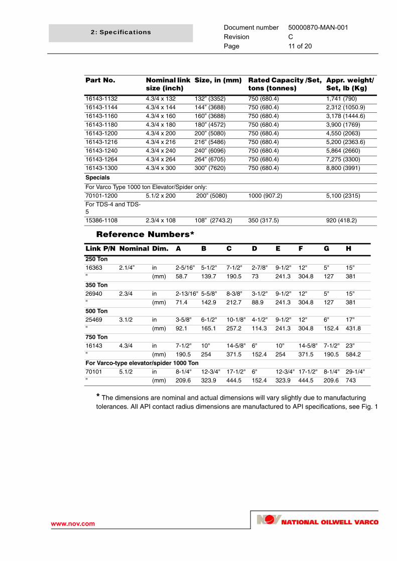
Reference Numbers*
* The dimensions are nominal and actual dimensions will vary slightly due to manufacturing tolerances. All API contact radius dimensions are manufactured to API specifications, see Fig. 1
Part No. Nominal link size (inch)
Size, in (mm) Rated Capacity /Set, tons (tonnes)
Appr. weight/Set, lb (Kg)
16143-1132 4.3/4 x 132 132” (3352) 750 (680.4) 1,741 (790)16143-1144 4.3/4 x 144 144” (3688) 750 (680.4) 2,312 (1050.9)
16143-1160 4.3/4 x 160 160” (3688) 750 (680.4) 3,178 (1444.6)
16143-1180 4.3/4 x 180 180” (4572) 750 (680.4) 3,900 (1769)16143-1200 4.3/4 x 200 200” (5080) 750 (680.4) 4,550 (2063)
16143-1216 4.3/4 x 216 216” (5486) 750 (680.4) 5,200 (2363.6)
16143-1240 4.3/4 x 240 240” (6096) 750 (680.4) 5,864 (2660)16143-1264 4.3/4 x 264 264” (6705) 750 (680.4) 7,275 (3300)
16143-1300 4.3/4 x 300 300” (7620) 750 (680.4) 8,800 (3991)
Specials
For Varco Type 1000 ton Elevator/Spider only:70101-1200 5.1/2 x 200 200” (5080) 1000 (907.2) 5,100 (2315)
For TDS-4 and TDS-5
15386-1108 2.3/4 x 108 108” (2743.2) 350 (317.5) 920 (418.2)
Link P/N Nominal Dim. A B C D E F G H250 Ton16363 2.1/4” in 2-5/16" 5-1/2" 7-1/2" 2-7/8" 9-1/2" 12" 5" 15"
" (mm) 58.7 139.7 190.5 73 241.3 304.8 127 381
350 Ton26940 2.3/4 in 2-13/16" 5-5/8" 8-3/8" 3-1/2" 9-1/2" 12" 5" 15"
" (mm) 71.4 142.9 212.7 88.9 241.3 304.8 127 381
500 Ton25469 3.1/2 in 3-5/8" 6-1/2" 10-1/8" 4-1/2" 9-1/2" 12" 6" 17"
" (mm) 92.1 165.1 257.2 114.3 241.3 304.8 152.4 431.8
750 Ton16143 4.3/4 in 7-1/2" 10" 14-5/8" 6" 10" 14-5/8" 7-1/2" 23"
" (mm) 190.5 254 371.5 152.4 254 371.5 190.5 584.2
For Varco-type elevator/spider 1000 Ton70101 5.1/2 in 8-1/4" 12-3/4" 17-1/2" 6" 12-3/4" 17-1/2" 8-1/4" 29-1/4"
" (mm) 209.6 323.9 444.5 152.4 323.9 444.5 209.6 743

Document number 50000870-MAN-001Revision CPage 12 of 20
2: Specifications
www.nov.com
Perfection links
Part No. Size, in (mm) Rated Cap/Set, tons (tonnes)
Weight/Set, lb (Kg)
Dimension X inch (mm))
200450-130 2” x 30” (50.8 x 762) 100 (89.3) 49 (108) 30 (762)
200450-136 2” x 36” (50.8 x 914) 100 (89.3) 58 (128) 36 (914)
200450-142 2” x 42” (50.8 x 1,067) 100 (89.3) 67 (148) 42 (1,067)200450-148 2” x 48” (50.8 x 1,219) 100 (89.3) 76 (168) 48 (1,219)
200450-160 2” x 60” (50.8 x 1,524) 100 (89.3) 95 (208) 60 (1,524)
5.00
9.00
X
2.00
3.12
Fig. 2

Document number 50000870-MAN-001Revision CPage 13 of 20
2: Specifications
www.nov.com
Link handle kitThe Link handle kit can be used in combination with any Manual Operated Elevator. It is developed for easier handling of links and functions as a safe gripping point when closing and opening elevators. It suitable for 250 (2.1/4”) and 350 (2.3/4”)ton links.
Part number 50006435.
Fitting
The handle(s) must be mounted to the eye of the link, and not to the shank.
Ensure no interference occurs between handle and elevator when rotating the elevator.
Fitted handle

Document number 50000870-MAN-001Revision CPage 14 of 20
2: Specifications
www.nov.com
Elevator link compatibility
*Requires link 7/8” - 1.3/4”
WARNING: Never use links which have a capacity too low for carrying the load intended (dynamic + static), even if the links may fit on the elevator.
Elevator links Top Drive Solid Body Elevator Rating250T 400T 500T 650T 750T
250 Ton 2.1/4" pn16363 yes no no no no350 Ton 2.3/4" pn26940 yes yes yes yes yes
500 Ton 3.1/2" pn 25469 no yes yes yes yes
750 Ton 4.3/4" pn16143 no no no yes yes
1000 Ton 5.1/2" pn70101 no no no no no
Elevator links Elevator Y series
YC MYC HYC YT HYT LYT* MYT250 Ton 2.1/4" pn16363 yes yes yes yes yes no yes350 Ton 2.3/4" pn26940 yes yes yes yes yes no yes
500 Ton 3.1/2" pn 25469 no no yes no yes no no
750 Ton 4.3/4" pn16143 no no no no no no no
1000 Ton 5.1/2" pn70101 no no no no no no no
Elevator links Elevator T(M)A series
TA 1.050 - 2.7/8 TMA 2.3/8 - 5TA 4.3/4 - 8.5/8up to 100 ton
TA 4.3/4 - 11.1/4150 ton only
250 Ton 2.1/4" pn16363 no yes yes yes
350 Ton 2.3/4" pn26940 no yes yes yes
500 Ton 3.1/2" pn 25469 no no no yes750 Ton 4.3/4" pn16143 no no no no
1000 Ton 5.1/2" pn70101 no no no no
Elevator links Elevator G series
MG RGG MGG GG HGG RGA GA GGA250 Ton 2.1/4" pn16363 yes yes yes yes no yes yes yes
350 Ton 2.3/4" pn26940 yes yes yes yes yes yes yes yes
500 Ton 3.1/2" pn 25469 no no yes yes yes no yes yes750 Ton 4.3/4" pn16143 no no no no yes no no no
1000 Ton 5.1/2" pn70101 no no no no no no no no
Elevator links Elevator X series
SLX 1.66-5.1/2
SLX5.1/2-24.1/2
SSD1.66-7.5/8
SSD8.5/8-10.3/4 + 11.3/4-14
SXexcept 350 ton
SX350 ton
SLX SD
250 Ton 2.1/4" pn16363 yes yes yes yes no yes yes
350 Ton 2.3/4" pn26940 yes yes yes yes yes yes yes500 Ton 3.1/2" pn 25469 no yes no yes yes yes yes
750 Ton 4.3/4" pn16143 no no no no no no no
1000 Ton 5.1/2" pn70101 no no no no no no no

Document number 50000870-MAN-001Revision CPage 15 of 20
2: Specifications
www.nov.com
NOTES:.
1. Compatibility is based on API 8C radii unless specific link part No's are listed.
2. If a link part No. is not listed, suitable fit with the SBE is to be confirmed
3. In some cases special links are required for use on Top Drive SBE's to permit proper operation of link tilt.
4. In general, an elevator will fit one size larger and one size smaller noted link. However, fit should always be confirmed when combining sizes of links and elevators.
Elevator links Elevator X seriesSMX 150 Ton
SMX250 + 350 Ton
250 Ton 2.1/4" pn16363 yes yes
350 Ton 2.3/4" pn26940 yes yes
500 Ton 3.1/2" pn 25469 no yes* (rotation limited)750 Ton 4.3/4" pn16143 no no
1000 Ton 5.1/2" pn70101 no no
Elevator linksCasing Elevators / Spiders Varco Type
Casing Elevators / Spiders BJ Type
200T 350T 500T750T14”
750T24.1/2”
1000T24.1/2”
250T 350T 500T 1000T
250 Ton 2.1/4" pn16363 yes yes no no no no yes no no no350 Ton 2.3/4" pn26940 yes yes yes no no no yes yes no no
500 Ton 3.1/2" pn 25469 yes yes yes yes yes no yes yes yes yes
750 Ton 4.3/4" pn16143 no no no yes yes yes no yes yes yes
1000 Ton 5.1/2" pn70101 no no no no no yes no no no no
Elevator links Riser handling solid body elevator rating250 T 400 T 500 T 650T 750 T 1000T
250 Ton 2.1/4" pn16363 yes no no no no no
350 Ton 2.3/4" pn26940 yes yes yes yes yes no
500 Ton 3.1/2" pn 25469 no yes yes yes yes no750 Ton 4.3/4" pn16143 no no no yes yes yes
1000 Ton 5.1/2" pn70101 no no no no yes yes
Elevator links BX1 BX2 BX3 BX4-35 450 T 500 T 350 T 350 T
250 Ton 2.1/4" pn16363 yes no no no
350 Ton 2.3/4" pn26940 yes yes yes yes500 Ton 3.1/2" pn 25469 yes yes yes yes
750 Ton 4.3/4" pn16143 no no yes yes
1000 Ton 5.1/2" pn70101 no no no no
Elevator links BX4-50 BX4-75 BX5 BXS, Slip type 500 T 750 T 1000 T 350 T
250 Ton 2.1/4" pn16363 no no no yes
350 Ton 2.3/4" pn26940 yes no no yes500 Ton 3.1/2" pn 25469 yes yes no yes
750 Ton 4.3/4" pn16143 yes yes yes no
1000 Ton 5.1/2" pn70101 no no yes no
*250 and 350 ton SMX elevators in combination with 500 ton links gives reduced rotation possibility. Be advised to use 350 ton links.
Document number 50000870-MAN-001Revision CPage 16 of 20
2: Specifications
www.nov.com
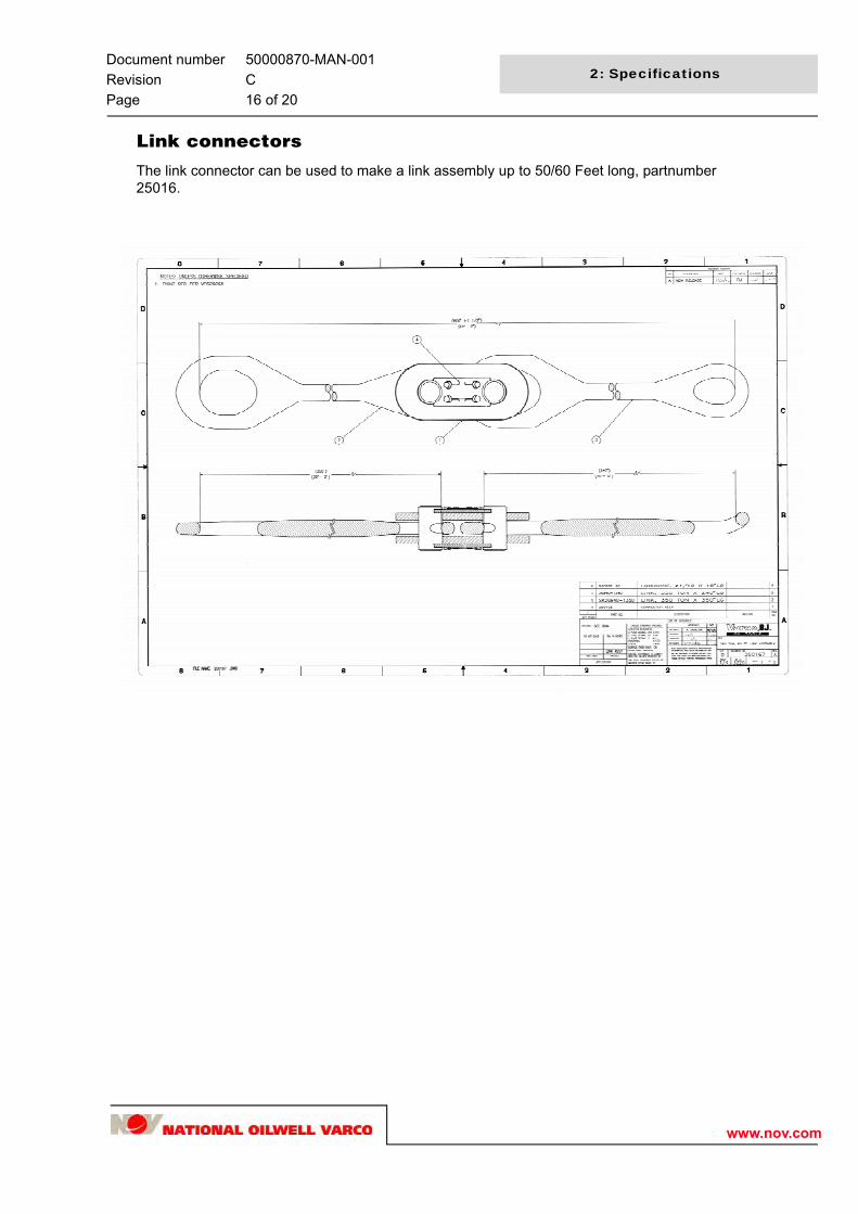
Link connectors
The link connector can be used to make a link assembly up to 50/60 Feet long, partnumber 25016.
Document number 50000870-MAN-001Revision CPage 17 of 20
3: Inspection and wear data
www.nov.com
Inspection & wear dataSafety
Wear chart shaft (shank)
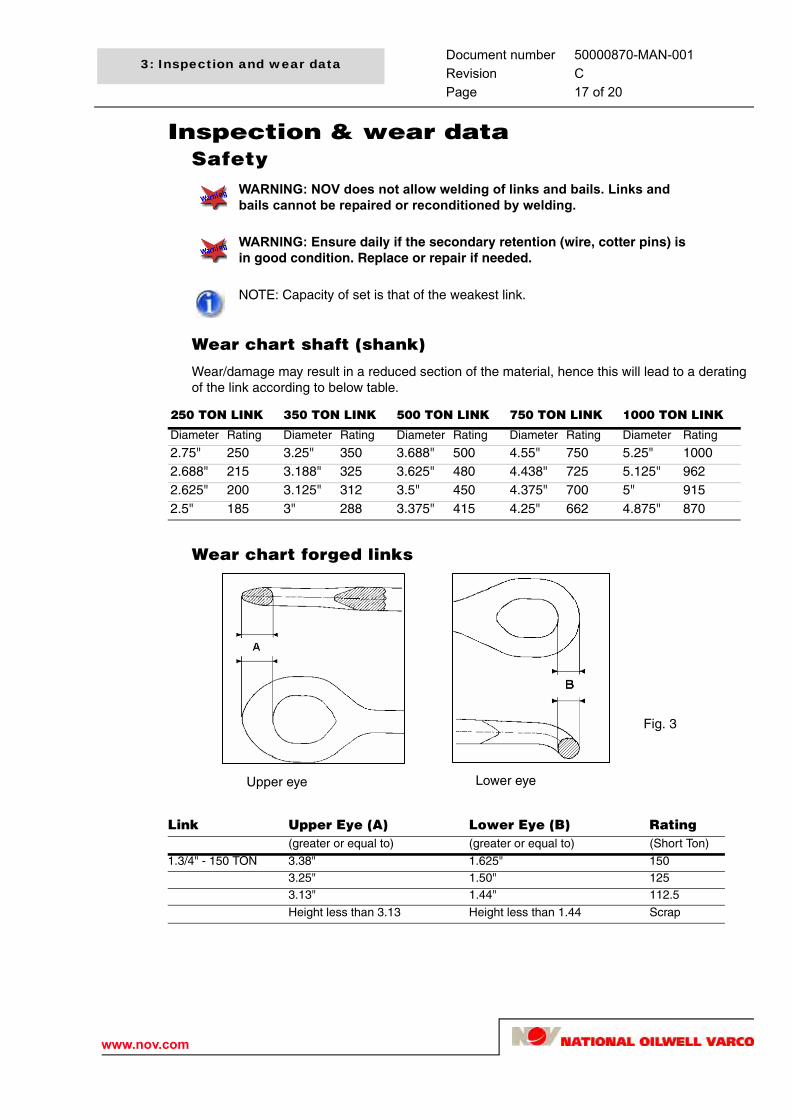
Wear/damage may result in a reduced section of the material, hence this will lead to a derating of the link according to below table.
Wear chart forged links
WARNING: NOV does not allow welding of links and bails. Links and bails cannot be repaired or reconditioned by welding.
WARNING: Ensure daily if the secondary retention (wire, cotter pins) is in good condition. Replace or repair if needed.
NOTE: Capacity of set is that of the weakest link.
250 TON LINK 350 TON LINK 500 TON LINK 750 TON LINK 1000 TON LINK
Diameter Rating Diameter Rating Diameter Rating Diameter Rating Diameter Rating
2.75" 250 3.25" 350 3.688" 500 4.55" 750 5.25" 10002.688" 215 3.188" 325 3.625" 480 4.438" 725 5.125" 9622.625" 200 3.125" 312 3.5" 450 4.375" 700 5" 9152.5" 185 3" 288 3.375" 415 4.25" 662 4.875" 870
Link Upper Eye (A) Lower Eye (B) Rating(greater or equal to) (greater or equal to) (Short Ton)
1.3/4" - 150 TON 3.38" 1.625" 1503.25" 1.50" 1253.13" 1.44" 112.5
Height less than 3.13 Height less than 1.44 Scrap
Upper eye Lower eye
Fig. 3

Document number 50000870-MAN-001Revision CPage 18 of 20
3: Inspection and wear data
www.nov.com
Wear data Perfection links.
Standard diameter of a Perfection link is 2.00”.
Minimum allowable diameter is 1.75”
Link Upper Eye (A) Lower Eye (B) Rating(greater or equal to) (greater or equal to) (Short Ton)
2.1/4" - 250 TON 4.75" 2.06" 2504.63" 1.88" 2004.5" 1.75" 180
Height less than 4.5" Height less than 1.75" Scrap
Link Upper Eye (A) Lower Eye (B) Rating(greater or equal to) (greater or equal to) (Short Ton)
2.3/4" - 350 TON 4.75" 2.56" 3504.63" 2.38" 2904.5" 2.25" 260
Height less than 4.50" Height less than 2.25" Scrap
Link Upper Eye (A) Lower Eye (B) Rating(greater or equal to) (greater or equal to) (Short Ton)
3.1/2" - 500 TON 5.625" 3.25" 5005.25" 3" 4405." 2.75" 375
Height less than 5" Height less than 2.75" Scrap
Link Upper Eye (A) Lower Eye (B) Rating(greater or equal to) (greater or equal to) (Short Ton)
750 TON 7" 7" 7506.75" 6.75" 7006.5" 6.5" 600
Height less than 6.5" Height less than 6.5" Scrap
Link Upper Eye (A) Lower Eye (B) Rating(greater or equal to) (greater or equal to) (Short Ton)
1000 TON 7.875" 7.875" 10007.5" 7.5" 9007.125" 7.125" 800
Height less than 7.125" Height less than 7.125" Scrap

Document number 50000870-MAN-001Revision CPage 19 of 20
3: Inspection and wear data
www.nov.com
MPI and inspectionReferences
1. ASTM E 709 (latest edition)
Standard Practice for Magnetic Particle Examination
2. ASTM A 275 (latest edition)
Standard Test Method for Magnetic Particle Examination of Steel Forgings.
3. API Specification 8A & 8C (latest edition)
4. API Recommended Practice RP 8B (latest edition)
Qualifications and certification
All personnel performing and interpreting examinations shall be qualified in accordance with the guidelines of ASNT-TC-1A (latest edition) or an equivalent standard recognized by ASNT. All personnel performing NDE shall also be trained in the NDE of forgings as well as trained in the interpretation of the MPI with regard to the acceptance criteria.
Evaluation of indications
Relevant indications:
Only those indications with major dimensions greater than 1/16 inch (1.6mm) and associated with a surface rupture shall be considered relevant. Relevant indications are indications that results from discontinuities within the test part. Non relevant indications are indications that results from excessive magnetizing current, structural design or permeability variances within the test parts. Any indication believed to be non relevant shall be regarded as relevant and shall be re-examined to determine whether an actual defect exists. Linear indications shall be considered as those having a length of more than three times the width. Rounded indications shall be considered as those having a length less than three times the width. Aligned indication should be considered as a group of three or more indications which touch an imaginary straight line connecting any two of the group.
Acceptance criteria
The link is considered critical in all area’s.
Equipment covered
Wrought material: In all cases as specified in the following table.
Relevant IndicationsNo relevant indications with a major dimension equal to or greater than 3/16 inch (4.8 mm)
No more than ten indications of 1/16 inch (1.6 mm) long or greater in
any continuous 6-square-inch (40 cm2) area
No more than three 1/16 inch (1.6 mm) long or greater indications in a line separated by less than 1/16 inch (1.6 mm) edge to edge

Document number 50000870-MAN-001Revision CPage 20 of 20
3: Inspection and wear data
www.nov.com