well test manager program user manual (for roc800-series
TRANSCRIPT

Remote Automation Solutions
Part Number D301750X012 August 2016
Well Test Manager Program User Manual (for ROC800-Series Remote Operations Controllers)

Well Test Manager Program User Manual (for ROC800-Series)
ii Revised Aug-16
Revision Tracking Sheet August 2016
This manual may be revised periodically to incorporate new or updated information. The revision date of each page appears at the bottom of the page opposite the page number. A change in revision date to any page also changes the date of the manual that appears on the front cover. Listed below is the revision date of each page (if applicable):
Page Revision All Pages August-2016 Initial release October-2015

Well Test Manager Program User Manual (for ROC800-Series)
Revised Aug-16 Contents iii
Contents Chapter 1 – Introduction 1
1.1 Scope and Organization ..................................................................................................................... 1 1.2 Product Overview ............................................................................................................................... 2 1.3 Program Features .............................................................................................................................. 3
1.3.1 Individual Well Meters .......................................................................................................... 3 1.3.2 Total Sales Meter and Virtual Well Meters .......................................................................... 3 1.3.3 Liquid or Oil Meters .............................................................................................................. 4 1.3.4 Automated Valves ................................................................................................................ 4 1.3.5 Manual Valves ..................................................................................................................... 4 1.3.6 Abort or Stop Commands .................................................................................................... 5 1.3.7 Additional Program Features ............................................................................................... 5
1.4 Functional Diagram ............................................................................................................................ 6 1.5 Typical Local/Remote Controlling Parameters ................................................................................... 7 1.6 Program Requirements ...................................................................................................................... 7
1.6.1 License Key.......................................................................................................................... 8
Chapter 2 – Installation 9
2.1 Installing the License Key .................................................................................................................. 9 2.1.1 Verifying the License Key Installation ................................................................................ 10
2.2 Downloading the Program ................................................................................................................ 10 2.3 MPU Loading Threshold (ROC800)................................................................................................... 15
Chapter 3 – Configuration 16
3.1 Configuring Well Test Setup ............................................................................................................ 16 3.2 Configuring Wells ............................................................................................................................. 28 3.3 Test Report ....................................................................................................................................... 36 3.4 Well Test Display – 11 Wells ............................................................................................................ 39 3.5 Saving the Configuration .................................................................................................................. 40
Chapter 4 – Reference 43
4.1 Point Type 62/211/215: Test Report Parameters ............................................................................ 44 4.2 Point Type 63/212/216: Well Test Setup Parameters ...................................................................... 48 4.3 Point Type 64/213/217: Wells .......................................................................................................... 61

Well Test Manager User Manual (for ROC800-Series)
iv Contents Revised Aug-16
[This page is intentionally left blank.]

Well Test Manager Program User Manual (for ROC800-Series)
Revised Aug-16 Introduction 1
Chapter 1 – Introduction
Caution When implementing control using this product, observe best industry practices as suggested by applicable and appropriate environmental, health, and safety organizations. While this product can be used as a safety component in a system, it is NOT intended or designed to be the ONLY safety mechanism in that system.
This chapter describes the structure of this manual and an overview of the Well Test Manager program for the ROC800-Series Remote Operations Controller (ROC800).
1.1 Scope and Organization This document serves as the user manual for the Well Test Manager program, which is intended for use in the ROC800-Series Remote Operations Controllers (ROC800).
This manual describes how to download and configure this program (referred to as the “Well Test Manager program” or “the program” throughout the rest of this manual). You access and configure this program using ROCLINK™ 800 Configuration Software (version 2.41 or greater) loaded on a personal computer (PC) running Windows® 7 (32 or 64-bit).
The sections in this manual provide information in a sequence appropriate for first-time users. Once you become familiar with the procedures and the software running in ROC800, the manual becomes a reference tool.
This manual has the following major sections:
Chapter 1 – Introduction Chapter 2 – Installation Chapter 3 – Configuration Chapter 4 – Reference
This manual assumes that you are familiar with the ROC800 and its configuration. For more information, refer to the following manuals:
ROC800 Remote Operations Controller Instruction Manual (Part D301217X012)
ROCLINK 800™ Configuration Software User Manual (for ROC800-Series) (Part D301250X012)
Well Test Manager User Manual (for ROC800-Series)
2 Introduction Revised Aug-16
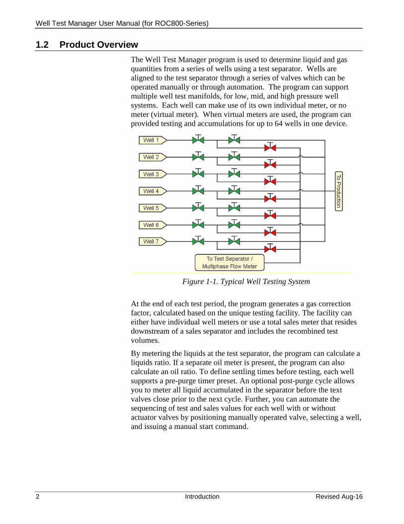
1.2 Product Overview The Well Test Manager program is used to determine liquid and gas quantities from a series of wells using a test separator. Wells are aligned to the test separator through a series of valves which can be operated manually or through automation. The program can support multiple well test manifolds, for low, mid, and high pressure well systems. Each well can make use of its own individual meter, or no meter (virtual meter). When virtual meters are used, the program can provided testing and accumulations for up to 64 wells in one device.
Figure 1-1. Typical Well Testing System
At the end of each test period, the program generates a gas correction factor, calculated based on the unique testing facility. The facility can either have individual well meters or use a total sales meter that resides downstream of a sales separator and includes the recombined test volumes.
By metering the liquids at the test separator, the program can calculate a liquids ratio. If a separate oil meter is present, the program can also calculate an oil ratio. To define settling times before testing, each well supports a pre-purge timer preset. An optional post-purge cycle allows you to meter all liquid accumulated in the separator before the text valves close prior to the next cycle. Further, you can automate the sequencing of test and sales values for each well with or without actuator valves by positioning manually operated valve, selecting a well, and issuing a manual start command.

Well Test Manager Program User Manual (for ROC800-Series)
Revised Aug-16 Introduction 3
For simultaneous train testing, you can load the Well Test Manager as multiple programs (for example, 11 wells = 3 trains, or 32 wells = 2 trains). For more details, see below.
Figure 1-2. Train System Options
1.3 Program Features
1.3.1 Individual Well Meters This configuration features individual well meters measuring two-phase flow through a physical meter (orifice, V-Cone®, or linear). During a well’s test cycle, the program determines the liquid or gas portion of volumes by comparing the test separator to the well measurement. It then applies a correction ratio factor to the well meter, isolating the gas portion of the flows and accumulators. When the well is in its off cycle, the correction ratio factor enables the program to estimate the gas-to-liquids split, which is re-adjusted when the well is retested.
1.3.2 Total Sales Meter and Virtual Well Meters This test method pairs a total sales meter with an upstream separator. This pairing allows the program to calculate a correction ratio by comparing the tested gas volume to the sales total. To enable this method, you select the Well Meters Virtual test method. Following the test cycle for an individual well, the program calculates and applies a gas correction factor. It then uses this factor to determine the percentage of the total sales meter for the well during an off-cycle.

Well Test Manager User Manual (for ROC800-Series)
4 Introduction Revised Aug-16
1.3.3 Liquid or Oil Meters The program calculates the liquid portion of a test using a test separator with either a common liquid meter or two meters measuring oil and water. Product composition (predominantly liquid or gas) determines which method the program uses to calculate liquid ratios during non-test cycles. If tank accumulated totals (available from Tank Manager) are available, then the program establishes Liq Vol/Liq Vol ratios during the same test cycle used to calculate well liquids during the non-test cycles. If you do not include Tank Manager accumulated totals, the program calculates Liq Vol/Gas Vol ratios using the tested gas portion for that cycle.
1.3.4 Automated Valves For each well that is enabled, a selection is possible to actuate a single solenoid for a test valve and one for a sales valve through digital output relays. If these are undefined, manually operated valves are assumed. Under the Valve Settings if the Momentary Time On (Sec) setting is non-zero, then options will appear for each well to define close momentary solenoids, and the open solenoids become momentary as well. The Valve Settings – Travel Time Before Fail setting also controls the sequencing delay as wells switch in and out of test. The delay ensures that each well’s flow is not interrupted by opening the both well valves on the current and previous well before closing the valves for the next test. To start the cycle for automated valves, use the Enable Test mode. In this mode, volumes will be accumulated for the preset Test Period in hours. Individual pre-purge presets can be defined for each well and a common post-purge preset time is possible if needed. If the test and sales limit switch selections are made for each well, failure actions can be defined for illegal valve positions with the Action On Failure selection. If no failure actions are selected, the valve limit switch states can be used for monitoring only. Another test mode is available called Test One Cycle that will Start from the current well and will test all enabled wells one time, and then automatically stop the cycle.
1.3.5 Manual Valves The Manual Valves Enable test mode allows you to manually operate test and sales valves. By defining a setpoint and using a local display or SCADA system, you can control the test cycle via Start, Stop, and Abort commands. You can also select a discrete input to manage the Stop or Abort commands. The program also provides a Timed Accum Stop

Well Test Manager Program User Manual (for ROC800-Series)
Revised Aug-16 Introduction 5
After Manual Start option that uses the Time Stop timer to stop the cycle.
This test mode supports a Valve DI mode, which you can use to set valve limit switches to DI Monitor Only or to use the same inputs as Start/Test Permissive values. Permissive selections ensure valves are in the correct positions before allowing a test cycle to start. Illegal permissive conditions either disable the Start command or abort the test cycle in progress.
If you choose the Force Well Selection option, you must re-select the Current Well after each test. This forces you to verify that the test well with the well aligned on the valve manifold.
1.3.6 Abort or Stop Commands All cycle modes support abort or stop actions, which advance the cycle to post-purge status. If you do not define a post-purge time, the cycle ends or advances. The Abort command does not apply new gas or liquid factors, but the Stop command immediately stops the test cycle and applies new gas or liquid factors. If you do not use the Timed Stop option with the Manual Valves Enabled test mode, you must use a Stop command to end the cycle. You can use a Stop command to interrupt a manual start with a defined Timed Stop option.
In the Enable Test mode, the Abort or Stop commands advance the cycle to the next available well after post-purge. If you issue a Stop command in the pre-purge cycle, the effect is the same as issuing an Abort command (that is, no new gas or liquid factors apply).
For operator control, Start, Abort, and Stop commands all support the ability to browse to an external DI push button. Alternately, the SCADA system or the local display can write the same internal variables to the program.
1.3.7 Additional Program Features Additional program feature include the abilities to:
Specify automated testing order for each well Insert a well into a testing order for a single instance Display status text messages (on a local display) Display alarm text messages (on a local display) Display current well text messages (on a local display) Log (optionally) status message alarms Log (optionally) gas correction factor events Apply (optionally) each well’s meter gas quality to the test meter Define minimum test times before the program applies correction
factors Use multiple validation modes including none, accept, accept/reject
and auto

Well Test Manager User Manual (for ROC800-Series)
6 Introduction Revised Aug-16
Define validation criteria, including a minimum threshold for gas correction factors and current versus last tolerances for gas, oil, and water factors
Use a program-provided test report point type to store well test results, which retains both currently and previously validated results. For backward compatibility, the program also retains the old softpoint table selection.
Hold last test results, which enables you to retest a well and then accept or reject both results into the test report (based on one set of hold registers for all wells)
Base (for gas production) liquid factors on liquid/gas ratios Base (for liquid production) liquid factors on total accumulation
values from Production Manager oil and water tanks. Normalize (optionally) off-cycle well gas correction and liquid ratios
so that all values equal 100% of sales measurement (applies only to virtual meters)
Detect post-purge cycle test valve leaks Estimate oil tank vapor Verify valve positions and define actions on failures Monitor shutdown valves for each well and define actions on
failures
1.4 Functional Diagram The functional diagram below represents the program features.
Figure 1-3. Functional Diagram

Well Test Manager Program User Manual (for ROC800-Series)
Revised Aug-16 Introduction 7
1.5 Typical Local/Remote Controlling Parameters Start – pushbutton or value; Manual Valves or One Cycle modes
only Abort – pushbutton or value; optional Stop – pushbutton or value; optional No Test Mode – Enable Test or One Cycle modes only; optional Hold Test Mode – Enable Test or One Cycle modes only; optional Shut All Mode – Enable Test or One Cycle modes only; optional Current Test Well Test Period Time / Timed Stop (hours) Post-Purge Time (hours); optional Insert Well Next Cycle Individual Wells – Pre-Purge Time (hours) Individual Wells – Enable/Disable Individual Wells – Test Order Individual Wells – Accept/Reject Test Individual Wells – Gas Correction Factor edit Individual Wells – Water Factor edit Individual Wells – Oil Factor edit Individual Wells – Shutdown; optional
1.6 Program Requirements The Well Test Manager program is compatible with version 3.61 (or greater) of the ROC800 firmware with version 2.41 (or greater) of the ROCLINK 800 software. Program specifics include:
Note: Load only one version of the program, depending on the number of wells supported:
The PMWTM_v413_00_T1_11w.tar program file supports 11 wells and installs in a ROC800 which requires only 1 license.
The PMWTM_v413_00_T1_32w.tar program file supports 32 wells and installs in a ROC800 which require 2 licenses.
The PMWTM_v413_00_T1_64w.tar program file supports 64 wells and installs in a ROC800 which require 3 licenses.
The PMWTM_v413_00_T2_11w.tar program file supports 11 wells and installs in a ROC800 which requires only 1 license.
The PMWTM_v413_00_T2_32w.tar program file supports 32 wells and installs in a ROC800 which require 2 licenses.
The PMWTM_v413_00_T3_11w.tar program file supports 11 wells and installs in a ROC800 which requires only 1 license.

Well Test Manager User Manual (for ROC800-Series)
8 Introduction Revised Aug-16
File Name Target Unit/ Version
User Defined Points (UDP)
Flash Used (in bytes)
DRAM Used (in bytes)
ROCLINK 800 Version
Display Number
PMWTM_v413_00_T1_11w.tar ROC800 v3.61 62, 63, 64 182404 139264 2.41 59, 62, 63, 64
PMWTM_v413_00_T1_32w.tar ROC800 v3.61 62, 63, 64 183219 151552 2.41 59, 62, 63, 64
PMWTM_v413_00_T1_64w.tar ROC800 v3.61 62, 63, 64 211978 163840 2.41 59, 62, 63, 64
PMWTM_v413_00_T2_11w.tar ROC800 v3.61 211, 212, 213 182404 139264 2.41 210, 211,
212, 213
PMWTM_v413_00_T2_32w.tar ROC800 v3.61 211, 212, 213 183219 151552 2.41 210, 211,
212, 213
PMWTM_v413_03_T3_11w.tar ROC800 v3.61 215, 216, 217 182404 139264 2.41 214, 215,
216, 217
For information on viewing the memory allocation of user programs, refer to the ROCLINK 800 Configuration Software User Manual (for ROC800) (part D301250X012).
1.6.1 License Key License keys, when matched with valid license codes, grant access to applications such as the Well Test Manager program. For ROC800, the term “license key” refers to the physical piece of hardware that can contain up to seven different licenses (refer to Figure 1-1). Each ROC800 can have none, one, or two license keys installed. If you remove a license key after enabling an application, the firmware disables the task from running. This prevents unauthorized execution of protected applications in a ROC800.
DOC0422A
J1
U1
Figure 1-4. License Key
Note: The Well Test Manager program for ROC800 requires up to 3 PMWTM license keys depending on your program requirement.

Well Test Manager Program User Manual (for ROC800-Series)
Revised Aug-16 Installation 9
Chapter 2 – Installation
This section provides instructions for installing the Well Test Manager program into the ROC800. Read Section 1.6 of this manual for program requirements.
Notes: The program and license key can be installed in any order. The
manual shows the installation of the license key first. The installation process and functionality is the same for all versions
of the Well Test Manager program.
2.1 Installing the License Key If you order the Well Test Manager program for a new ROC800, your ROC800 is delivered with the license key installed.
If you order the program for an existing ROC800, you must install the license key yourself.
Caution Failure to exercise proper electrostatic discharge precautions, such as wearing a grounded wrist strap may reset the processor or damage electronic components, resulting in interrupted operations.
When working on units located in a hazardous area (where explosive gases may be present), make sure the area is in a non-hazardous state before performing these procedures. Performing these procedures in a hazardous area could result in personal injury or property damage.
To install a license key:
1. Remove power from the ROC800.
2. If necessary, remove the wire channel cover.
3. Unscrew the screws from the Central Processing Unit (CPU) faceplate.
4. Remove the CPU faceplate.
5. Place the license key in the appropriate terminal slot (P4 or P6) in the CPU (refer to Figure 2-1).
Figure 2-1. License Key Installation
Note: When using a single license key, install it in slot P4.

Well Test Manager User Manual (for ROC800-Series)
10 Installation Revised Aug-16
6. Press the license key into the terminal until it is firmly seated (refer to Figure 2-1).
7. Re-attach the CPU faceplate.
8. Re-attach the screws on the CPU faceplate.
9. If necessary, re-attach the wire channel cover.
10. Restore power to the ROC800.
2.1.1 Verifying the License Key Installation After you install the license key, you can verify whether the ROC800 recognizes the key. From the ROCLINK 800 screen, select Utilities > License Key Administrator. The License Key Administrator screen displays:
Figure 2-2. License Key Administrator
The Well Test Manager program appears in the Application Name column. (For further information on the License Key Administrator screen, refer to the ROCLINK 800 Configuration Software User Manual (for ROC800-Series), part D301250X012.)
After you verify that the license key is correctly installed and recognized, proceed to Section 2.2.
2.2 Downloading the Program This section provides instructions for installing the program into the Flash memory on the ROC800.
To download the user program using ROCLINK 800 software:
1. Connect the ROC800 to your computer.
2. Start and logon to the ROCLINK 800.

Well Test Manager Program User Manual (for ROC800-Series)
Revised Aug-16 Installation 11
3. Select ROC > Direct Connect to connect to the ROC800.
4. Select Utilities > User Program Administrator from the ROCLINK menu bar. The User Program Administrator screen displays (see Figure 2-3):
Figure 2-3. User Program Administrator
5. Select any empty program number (in this case, number 1) into which to download the program.
6. Click Browse in the Download User Program File frame. The Select User Program File screen displays (see Figure 2-4).
7. Select the path and user program file to download from the CD-ROM. (Program files are typically located in the Program Files folder on the CD-ROM.) As Figure 5 shows, the screen lists all valid user program files with the .TAR extension:

Well Test Manager User Manual (for ROC800-Series)
12 Installation Revised Aug-16
Figure 2-4. Select User Program File
8. Click Open to select the program file. The User Program Administrator screen displays. As shown in Figure 2-5, note that the Download User Program File frame identifies the selected program and that the Download & Start button is active:
Figure 2-5. User Program Administrator

Well Test Manager Program User Manual (for ROC800-Series)
Revised Aug-16 Installation 13
9. Click Download & Start to begin loading the selected program. The following message displays:
Figure 2-6. Confirm Download
10. Click Yes to begin the download. When the download completes the following message displays:
Figure 2-7. ROCLINK 800 Download Confirmation
11. Click OK. The User Program Administrator screen displays (see Figure 2-8). Note that:
The Device User Program Environment frame reflects the use of system memory.
The User Programs Installed in Device frame identifies the installed program(s).
The Status field indicates that the program is running.

Well Test Manager User Manual (for ROC800-Series)
14 Installation Revised Aug-16
Figure 2-8. User Program Administrator
12. Click Close. The ROCLINK 800 screen displays and the download is complete.
Figure 2-9. ROCLINK 800
13. Proceed to Chapter 3 – Configuration to configure the program.

Well Test Manager Program User Manual (for ROC800-Series)
Revised Aug-16 Installation 15
2.3 MPU Loading Threshold (ROC800) To maximize the performance of your ROC800 device, always verify the performance of specific application combinations before using them in the field to ensure the MPU load typically remains below 85% with peak MPU loading levels below 95%.
To check the current MPU load at any time, select ROC > Information > Other Information and review the value in the MPU loading field.
Figure 2-10. MPU Loading

Well Test Manager User Manual (for ROC800-Series)
16 Configuration Revised Aug-16
Chapter 3 – Configuration
This section provides information to configure the Well Test Manager program.
After you have download and start the Well Test Manager program, you can configure the program-specific screen using ROCLINK 800 software. The following program-specific screens are:
Well Test Test Report Well Test Setup Wells
Note: This document demonstrates the installation of Train 1 version,
11 wells. The installation process and functionality is the same to all program versions. Refer to Section 1.6, for more information.
3.1 Configuring Well Test Setup Once you have successfully loaded the Well Test Manager program into the ROC800, you can access the Well Test Setup screen. This screen is used to configure the operating mode of the system, the test separator I/O, and other functionality which is global to the entire program. Items such as the test period and the valve behavior configured on this screen will apply to all wells.
To access the Well Test Setup screen:
1. From the Directory Tree, select User Program > Program #1, PMWTM_v413_00_T1_11w.
2. Double-click Display #63, Well Test Setup 1. The Well Test Setup screen appears:
Well Test Manager Program User Manual (for ROC800-Series)
Revised Aug-16 Configuration 17
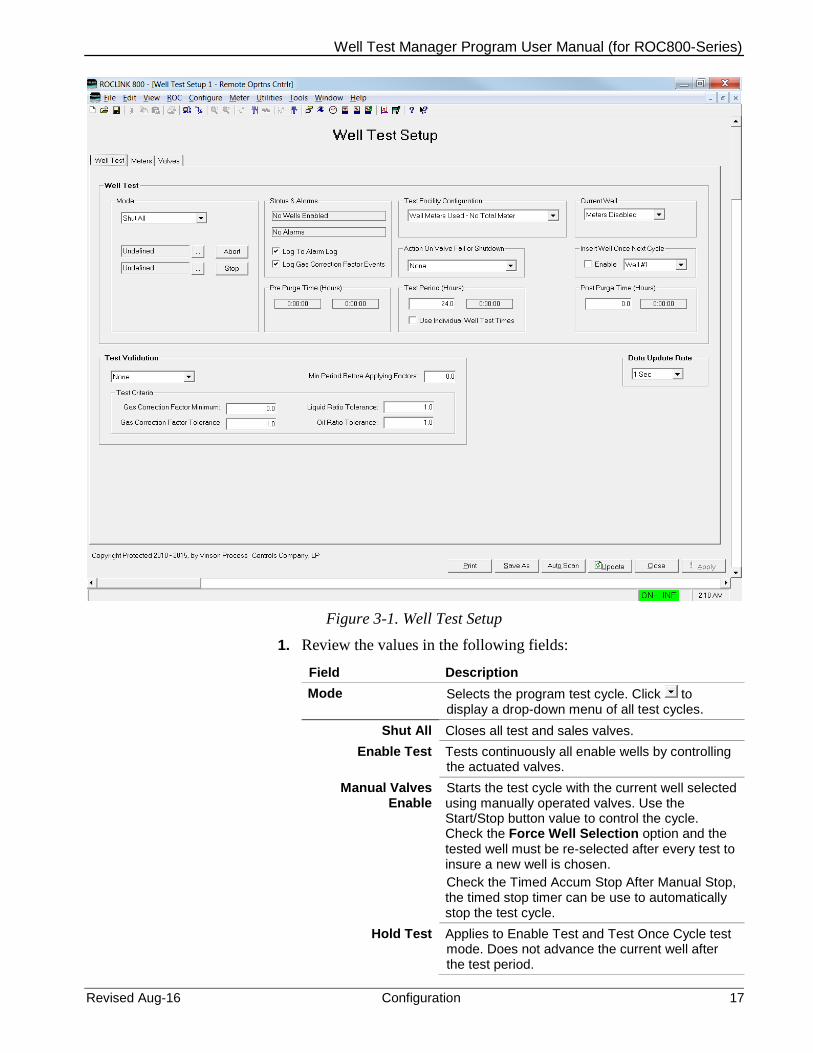
Figure 3-1. Well Test Setup
1. Review the values in the following fields: Field Description Mode Selects the program test cycle. Click to
display a drop-down menu of all test cycles. Shut All Closes all test and sales valves.
Enable Test Tests continuously all enable wells by controlling the actuated valves.
Manual Valves Enable
Starts the test cycle with the current well selected using manually operated valves. Use the Start/Stop button value to control the cycle. Check the Force Well Selection option and the tested well must be re-selected after every test to insure a new well is chosen. Check the Timed Accum Stop After Manual Stop, the timed stop timer can be use to automatically stop the test cycle.
Hold Test Applies to Enable Test and Test Once Cycle test mode. Does not advance the current well after the test period.
Well Test Manager User Manual (for ROC800-Series)
18 Configuration Revised Aug-16
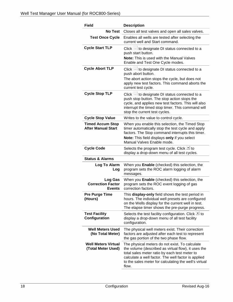
Field Description No Test Closes all test valves and open all sales valves.
Test Once Cycle Enables all wells are tested after selecting the current well and Start command.
Cycle Start TLP Click to designate DI status connected to a push start button. Note: This is used with the Manual Valves Enable and Test One Cycle modes.
Cycle Abort TLP Click to designate DI status connected to a push abort button. The abort action stops the cycle, but does not apply new test factors. This command aborts the current test cycle.
Cycle Stop TLP Click to designate DI status connected to a push stop button. The stop action stops the cycle, and applies new test factors. This will also interrupt the timed stop timer. This command will stop the current test cycles.
Cycle Stop Value Writes to the value to control cycle. Timed Accum Stop After Manual Start
When you enable this selection, the Timed Stop timer automatically stop the test cycle and apply factors. The Stop command interrupts this timer. Note: This field displays only if you select Manual Valves Enable mode.
Cycle Code Selects the program test cycle. Click to display a drop-down menu of all test cycles.
Status & Alarms Log To Alarm
Log When you Enable (checked) this selection, the program sets the ROC alarm logging of alarm messages.
Log Gas Correction Factor
Events
When you Enable (checked) this selection, the program sets the ROC event logging of gas correction factors.
Pre Purge Time (Hours)
This display-only field shows the test period in hours. The individual well presets are configured on the Wells display for the current well in test. The elapse timer shows the pre-purge progress.
Test Facility Configuration
Selects the test facility configuration. Click to display a drop-down menu of all test facility configuration.
Well Meters Used (No Total Meter)
The physical well meters exist. Their correction factors are adjusted after each test to represent the gas portion of the two phase flow.
Well Meters Virtual (Total Meter Used)
The physical meters do not exist. To calculate the volume (described as virtual flow), it uses the total sales meter ratio by each test meter to calculate a well factor. The well factor is applied to the sales meter for calculating the well’s virtual flow.
Well Test Manager Program User Manual (for ROC800-Series)
Revised Aug-16 Configuration 19
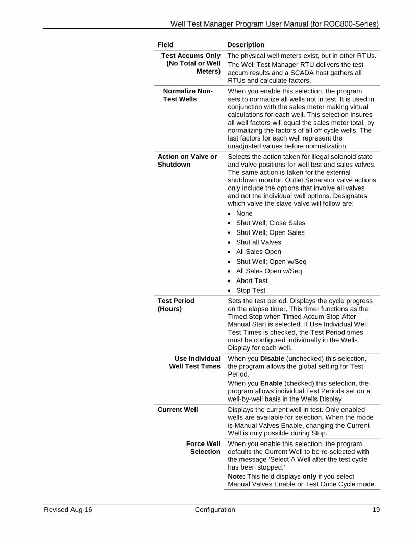
Field Description Test Accums Only
(No Total or Well Meters)
The physical well meters exist, but in other RTUs. The Well Test Manager RTU delivers the test accum results and a SCADA host gathers all RTUs and calculate factors.
Normalize Non-Test Wells
When you enable this selection, the program sets to normalize all wells not in test. It is used in conjunction with the sales meter making virtual calculations for each well. This selection insures all well factors will equal the sales meter total, by normalizing the factors of all off cycle wells. The last factors for each well represent the unadjusted values before normalization.
Action on Valve or Shutdown
Selects the action taken for illegal solenoid state and valve positions for well test and sales valves. The same action is taken for the external shutdown monitor. Outlet Separator valve actions only include the options that involve all valves and not the individual well options. Designates which valve the slave valve will follow are: • None • Shut Well; Close Sales • Shut Well; Open Sales • Shut all Valves • All Sales Open • Shut Well; Open w/Seq • All Sales Open w/Seq • Abort Test • Stop Test
Test Period (Hours)
Sets the test period. Displays the cycle progress on the elapse timer. This timer functions as the Timed Stop when Timed Accum Stop After Manual Start is selected. If Use Individual Well Test Times is checked, the Test Period times must be configured individually in the Wells Display for each well.
Use Individual Well Test Times
When you Disable (unchecked) this selection, the program allows the global setting for Test Period. When you Enable (checked) this selection, the program allows individual Test Periods set on a well-by-well basis in the Wells Display.
Current Well Displays the current well in test. Only enabled wells are available for selection. When the mode is Manual Valves Enable, changing the Current Well is only possible during Stop.
Force Well Selection
When you enable this selection, the program defaults the Current Well to be re-selected with the message ‘Select A Well after the test cycle has been stopped.’ Note: This field displays only if you select Manual Valves Enable or Test Once Cycle mode.

Well Test Manager User Manual (for ROC800-Series)
20 Configuration Revised Aug-16
Field Description Insert Well Once Next Cycle
When you enable this selection, the program sets the well to be inserted in the test cycle by selecting the well to insert. Click and select the next well for testing. Note: This field is not available if you select Manual Valves Enable mode.
Post Purge Time (Hours)
Sets the purge time to be set in hours. The elapsed timer displays the post-purge progress. This is useful to allow the liquid dumps to finish and accumulate the remaining liquids. Enter zero if no post-purge is needed.
Test Validation Displays the test validation mode. Click and select from the following Test Validation Modes: • None – This test validation mode means ‘No
Test Criteria’ is used before factors are accepted. Status message alarms are available from the last cycle or from the ROC alarm log. Accept Test Only – This test validation means only accepted tests appear in softpoint table as test reports. Date/Time stamp factors, accums and alarms are kept as last values until they are accepted and recorded as current values in the Test Report. The last test values are kept for each well until the well is tested again. Status message alarms or ROC alarm log information is available to manually determine if a test is valid before accepting.
• Accept or Reject Test – This test validation means only accepted and rejected tests appear in softpoint table as test reports. A softpoint table byte indicates this is an Accepted or Rejected report. Date/Time stamp factors, accums and alarms are kept as last values until they are accepted and recorded as current values in the Test Report. Reject will push last values into the test report. The last test values are kept for each well until the well is tested again. Status message alarms or ROC alarm log information is available to manually determine if a test is valid before accepting or rejecting.
• Auto Accept – This test validation means by default the current test is accepted.
Wells UnAcknowledged
Displays total enable wells, tested and are waiting for acceptance. Note: This field displays only if you select Accept Test Only or Accept or Reject Test mode.
Minimum Period Before Applying Factors (Hours)
Determines all factors are use or discard when the Test Period Cycle is interrupted before a complete cycle.
Test Criteria

Well Test Manager Program User Manual (for ROC800-Series)
Revised Aug-16 Configuration 21
Field Description Gas Correction
Factor Minimum You enter a low limit minimum to prevent unrealistic factors. A high limit maximum of 1.0 is imposed by the program. If a minimum or maximum condition is encountered, the last good gas correction factor is used.
Gas Correction Factor Tolerance
Sets the tolerance between the last gas factor and the current gas factor.
Liquid Ratio Tolerance
Sets the tolerance between the last water factor and the current water factor.
Oil Ratio Tolerance
Sets the tolerance between the last oil factor and the current oil factor
Data Update Rate Selects for the program to improve MPU loading in larger well version with slower data updates for selected TLPs. Click to display a drop-down menu of data update rate (1, 2, 4, 6, 8, 10 Sec).
2. Click on the Meters tab.
Figure 3-2. Meters Screen

Well Test Manager User Manual (for ROC800-Series)
22 Configuration Revised Aug-16
3. Review the values in the following fields: Field Description Test Meter
Measurement Type Indicates the behavior of the TLP selected on the Meter Selection field. Note that this field only displays if you select the test facility configuration option of Test Accums Only. Select from the following options: • Accum – This parameter is an accumulator
value. • Flow – This parameter is a flow rate value.
Meter Selection Click to designate the desired TLP (Orifice or Turbine flow rate) for the test meter. A pulse input (PI) or Advanced Pulse Module (APM) flowrate or accumulation may be used. A ROC800L Liquid Meter may also be selected. Selection of an external accumulator is also possible from a softpoint. If the rollover point of the selected accum is not known, then set the External Liquid Meters Rollover value to zero.
Flow This is read-only field displays the flow rate for the test meter.
Accum For Period This is read-only field displays the volume accumulation for the test time period.
Apply Tested Meter Gas Quality
When you enable (checked) this selection, the ROC station gas quality of the well tested to the test meter is the same composition basis used to calculate the gas correction factor. Note: This field displays only if you select the Test Facility Configuration option of Well Meters Used.
Test Valve Leak Delay Preset (Sec)
Sets the post-purge timer used actuated test and sales valves. When this delay is in the post-purge cycle, the test meter is checked for low flow to insure the test valves are not leaking. The Alarm Message and Alarm Log indicate an illegal flow condition. Note: This field displays only if a valid post purge time has been entered and manual valves are not in use.
Test Valve Leak Low Flow
Sets the low flow threshold that indicates that a test valve is leaking during the purge cycle. The Alarm Message and Alarm Log show this illegal flow condition. Note: This field displays only if a valid post purge time has been entered and manual valves are not in use.
Sales Total Meter

Well Test Manager Program User Manual (for ROC800-Series)
Revised Aug-16 Configuration 23
Field Description Measurement Type Indicates the behavior of the TLP selected on
the Meter Selection field. Note that this field only displays if you select the test facility configuration option of Test Accums Only. Select from the following options: • Accum – This parameter is an accumulator
value. • Flow – This parameter is a flow rate value.
Meter Selection Click to designate the desired TLP (Orifice or Turbine flow rate) for the meter. A pulse input (PI) or Advanced Pulse Module (APM) flow rate or accumulation may be used. A ROC800L Liquid Meter may also be selected. Selection of an external accumulator is also possible from a Softpoint. If the rollover point of the selected accum is not known, then set the External Liquid Meters Rollover value to zero. Note: This field displays only if you select the Test Facility Configuration option of Well Meters Virtual.
Flow This is read-only field displays the flow rate for the sales meter selected.
Accum For Period This is read-only field displays the sales volume accumulation for the test period.
Test Water or Total Liquid
Measurement Type Indicates the behavior of the TLP selected on the Meter Selection field. Note that this field only displays if you select the test facility configuration option of Test Accums Only. Select from the following options: • Accum – This parameter is an accumulator
value. • Flow – This parameter is a flow rate value.
Meter Selection Click to designate the desired TLP (Orifice or Turbine flow rate) for the meter. A ROC800L Liquid Meter may also be selected. Selection of an external accumulator is also possible from a Softpoint. If the rollover point of the selected accum is not known, then set the External Liquid Meters Rollover value to zero.
Flow (EU/Day) This is read-only field displays the flow rate for the liquid meter selected. The EU units will be what the ROC pulse input conversion represents. Flow is not calculated for externally selected accums.
Accum For Period This is read-only field displays the liquid volume accumulation for the test period.

Well Test Manager User Manual (for ROC800-Series)
24 Configuration Revised Aug-16
Field Description Total Accum This is read-only field displays the total liquid
volume accumulation. If this value is brought in externally as a Softpoint value, use the External Liquid Meters Rollover value to determine when the value will roll to zero.
Test Oil Measurement Type Indicates the behavior of the TLP selected on
the Meter Selection field. Note that this field only displays if you select the test facility configuration option of Test Accums Only. Select from the following options: • Accum – This parameter is an accumulator
value. • Flow – This parameter is a flow rate value.
Meter Selection Click to designate the desired TLP (Orifice or Turbine flow rate) for the oil meter. A Pulse Input (PI) or Advanced Pulse Module (APM) flowrate or accumulation may be used. A ROC800L Liquid Meter may also be selected. The meter is used for the oil ratio calculation. Selection of an external accumulator is also possible from a Softpoint. If the rollover point of the selected accum is not known, then set the External Liquid Meters Rollover value to zero.
Flow (EU/Day) This read-only field displays the flow rate for the oil meter selected. The EU units will be what the ROC pulse input conversion represents. Flow is not calculated for externally selected accums.
Accum For Period This read-only field displays the oil volume accumulation for the test period.
Total Accum This read-only field displays the total oil volume accumulation. If this value is brought in externally as a Softpoint value, use the External Liquid Meters Rollover value to determine when the value will roll to zero.
Water Entrained in Oil Pct.
Sets the percentage of the measured oil for the test separator which is expected to be water or other non-merchantable product. Also referred to as the sediment and water percentage.
Water Tanks Total Water Selection Click to designate the desired TLP of the
Production Manager total tank accum for water (Point Type = 196, Parameter = 87).
Accum For Period This read-only field displays the water tank accumulation for the test period.
Total Accum This read-only field displays the Production Manager total water tank accum value.

Well Test Manager Program User Manual (for ROC800-Series)
Revised Aug-16 Configuration 25
Field Description Deduct Selection Click to designate the desired TLP of any
measurement representing an accumulation that should be deducted from the total water tank.
Deduct For Period This read-only field displays the water deduct accumulation for the test period.
Deduct Total This read-only field displays the deduct water accum value.
Oil Tanks Total Oil Selection Click to designate the desired TLP of the
Production Manager total tank accum for oil (Point Type = 196, Parameter = 86).
Accum For Period This read-only field displays the oil tank accumulation for the test period.
Total Accum This read-only field displays the Production Manager total oil tank accum value.
Deduct Selection Click to designate the desired TLP of any measurement representing an accumulation that should be deducted from the total oil tank.
Deduct For Period This read-only field displays the oil deduction amount for the test period.
Deduct Total This read-only field displays the deduct oil accum value.
Oil Tank Vapors Vapor Factor Sets the estimated vapour content for a given
volume of oil. Vapor Total This read-only field displays the vapors based
on tank volumes times the Oil Vapor Factor. The Total Accum Value should represent the total of all tanks, and may need to be summed externally.
External Liquid Meters Rollover
Sets the rollover value known point where this external value rolls over and accumulates again from zero. Enter zero for not known or not used. Note: This field functions with the water or oil for instance when a wireless connection to a remote meter provides a total accumulation as the Meter Selected Softpoint value.
4. Click on the Valves tab.

Well Test Manager User Manual (for ROC800-Series)
26 Configuration Revised Aug-16
Figure 3-3. Valves Screen
5. Review the values in the following fields: Field Description Valve Settings
Travel Time Before Fail (Sec)
Sets the two separate time functions: • If the test and sales limit switches are
defined, the time represents the time allowed for all valves to travel before the well is flagged for failure.
• If test and sales limit switches are not defined, the time represents a delay between valve sequencing giving valves time to travel.
Valve State Comparison
Selects the comparison of the DO solenoid state with the expected valve limit switch state after the valve travels. The comparison is made if the valve limit switches are defined and after the valve travel timer expires. Click and select valid values: • Direct – This comparison is the test valve
solenoid is open (State = 1) and its open limit switch is made (State = 1).
• Reversed – This comparison is the opposite for either state.
Solenoid DO Invert
Sets the DO actuation states to be Reversed. Click and select Reversed. Note: To invert DI limit switch states, use the ROC Discrete Input - Advanced Inverted setting.
Momentary Time On (Sec)
Sets the momentary reset times in a dual solenoid configuration for each valve. You enter zero, assumes one solenoid latched configuration. If solenoid DOs are selected for each well’s valves, this setting will configure the Time On setting for each DO selected.
Well Test Manager Program User Manual (for ROC800-Series)
Revised Aug-16 Configuration 27
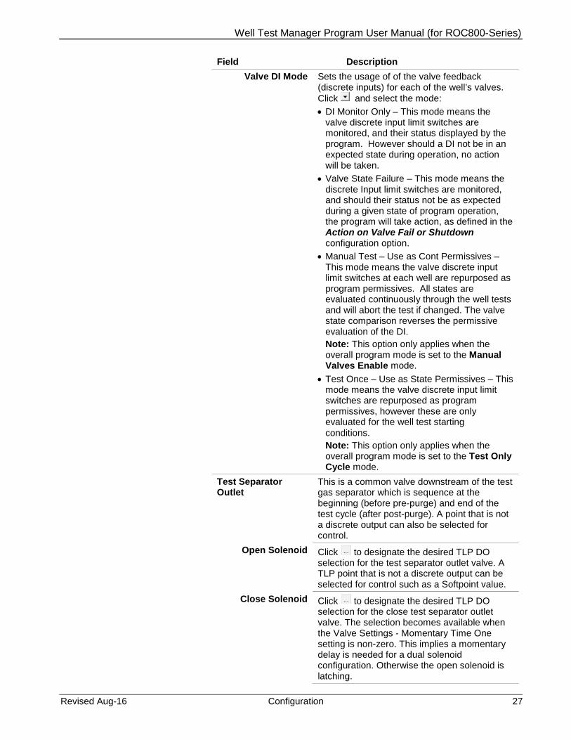
Field Description Valve DI Mode Sets the usage of of the valve feedback
(discrete inputs) for each of the well’s valves. Click and select the mode: • DI Monitor Only – This mode means the
valve discrete input limit switches are monitored, and their status displayed by the program. However should a DI not be in an expected state during operation, no action will be taken.
• Valve State Failure – This mode means the discrete Input limit switches are monitored, and should their status not be as expected during a given state of program operation, the program will take action, as defined in the Action on Valve Fail or Shutdown configuration option.
• Manual Test – Use as Cont Permissives – This mode means the valve discrete input limit switches at each well are repurposed as program permissives. All states are evaluated continuously through the well tests and will abort the test if changed. The valve state comparison reverses the permissive evaluation of the DI. Note: This option only applies when the overall program mode is set to the Manual Valves Enable mode.
• Test Once – Use as State Permissives – This mode means the valve discrete input limit switches are repurposed as program permissives, however these are only evaluated for the well test starting conditions. Note: This option only applies when the overall program mode is set to the Test Only Cycle mode.
Test Separator Outlet
This is a common valve downstream of the test gas separator which is sequence at the beginning (before pre-purge) and end of the test cycle (after post-purge). A point that is not a discrete output can also be selected for control.
Open Solenoid Click to designate the desired TLP DO selection for the test separator outlet valve. A TLP point that is not a discrete output can be selected for control such as a Softpoint value.
Close Solenoid Click to designate the desired TLP DO selection for the close test separator outlet valve. The selection becomes available when the Valve Settings - Momentary Time One setting is non-zero. This implies a momentary delay is needed for a dual solenoid configuration. Otherwise the open solenoid is latching.

Well Test Manager User Manual (for ROC800-Series)
28 Configuration Revised Aug-16
Field Description Open Limit
Switch Click to designate the desired TLP DI selection for the test separator outlet valve open limit switch. This selection is optional. Use the ROC DI Inverted setting to make the display Open message appear correctly for a normally closed wiring scheme. Note: The Valve Settings - Valve DI Mode controls the use of this point.
Close Limit Switch
Click to designate the desired TLP DI selection for the test separator outlet valve close limit switch. This selection is optional. Use the ROC DI Inverted setting to make the display Close message appear correctly for a normally closed wiring scheme. Note: The Valve Settings - Valve DI Mode controls the use of this point.
Delay Preset (Sec)
Sets the preset in seconds use for the test separator outlet valve after valve open and before valve close.
Timer Sec This read-only field displays the decrementing timer in seconds use for the test separator outlet valve after valve open and before valve close.
6. Proceed to Section 3.2 – Configuring wells.
3.2 Configuring Wells Once you have successfully loaded the Well Test Manager program into the ROC800, you can access the Well screen. This screen is used to configure inputs and outputs that are specific to the well. This is also where current well values, including allocation accumulations can be viewed. There are multiple instances (or points) available for this screen, each representing a different well. Configuration on this screen must be repeated for each well to be supported by the program.
To access the Well screen:
1. From the Directory Tree, select User Program > Program #1, PMWTM_v413_00_T1_11w.
2. Double-click Display #64, Well 1. The Well screen appears:

Well Test Manager Program User Manual (for ROC800-Series)
Revised Aug-16 Configuration 29
Figure 3-4. Well screen
3. Review the following fields:
Field Description
Point Number Displays selection for the well. Click and select a well. The tag can be any 10 character description.
Cycle Information
Status Message This read-only field displays the cycle related messages.
Last Alarm This read-only field displays the test related alarm messages.
Current Well This read-only field displays the current well in test.
Pre Purge (Hours)
Sets a pre-purge preset you enter for each well. Displays a decrementing pre-purge timer.

Well Test Manager User Manual (for ROC800-Series)
30 Configuration Revised Aug-16
Field Description
Test Period (Hours)
This read-only field displays the test period preset and the decrementing test period timer. If the Use Individual Well Test Times setting is checked in the Test Setup, individual test period presets are entered for each well.
Post Purge (Hours)
This read-only field displays the post-purge preset and displays the decrementing post-purge timer.
Well Meter
Enable When you enable (checked) this selection, the meter is available for testing. For the Enable Test or Test One Cycle mode, the next available well will be tested if the well is disabled. For the Manual Valves Enable mode, a test will be prevented if the well is disabled. The program can also disable a well if one of the Shut Well options is selected under Action On Valve Fail or Shutdown. If Normalize Non-Test Factors is checked, enabling or disabling a well will case factors to be renormalized.
Test Order Sets the numeric order of test wells. The next greater value in order is always tested next. If all test order values are the same, the wells will be tested in the order each well instance is configured.
Measurement Type Indicates the behavior of the TLP selected on the Meter Selection field. Note that this field only displays if you select the test facility configuration option of Test Accums Only. Select from the following options: • Accum – This parameter is an accumulator
value. • Flow – This parameter is a flow rate value. • Specified SoftPt Order – this parameter is
part of a set of meter data from a remote device saved into soft point float parameters. Note: When selecting this option, the following soft point float data values must be populated in the parameters as shown. Float data values not listed below are not used by the program. • SoftPt X, Float 4 = Flow Rate • SoftPt X, Float 5 = Today's Accum • SoftPt X, Float 6 = Yest's Accum • SoftPt X, Float 9 = Volume Accumulated • SoftPt X, Float 11 = Specific Gravity • SoftPt X, Float 13 = N2 % • SoftPt X, Float 14 = CO2

Well Test Manager Program User Manual (for ROC800-Series)
Revised Aug-16 Configuration 31
Field Description
Meter Selection Click to designate the desired TLP (Orifice or Turbine flow rate) for the meter. A pulse input (PI) or Advanced Pulse Module (APM) flowrate or accumulation may be used. A ROC800L Liquid Meter may also be selected. Selection of an external accumulator is also possible from a Softpoint. If the rollover point of the selected accum is not known, then set the External Liquid Meters Rollover value to zero. Note: This selection is not used for virtual meters.
Gas Flow This read-only field displays the flow of an actual meter.
Gas Accum For Period
This read-only field displays the accum from the test meter for the tested period.
Gas Correction Factor
Sets the ratio of test meter and well meter accumulations for the test period. By multiplying this factor to the well flow calculation, the well flow will be adjusted to reflect the estimated gas portion of the well flow. The first averaging period for each well will reflect gas and liquid until the first gas correction factor is applied. If the gas correction factor is adjusted manually, the period cycle will restart to avoid problems with partial accumulations using the old factor. If Use Sales Total For Virtual Calcs is selected, this factor becomes the percentage of the sales meter total flows and accums that represents this well. If no validation is selected, the last gas correction factor is immediately pushed into the gas correction factor.
Last Gas Correction Factor
This read-only field displays the un-validated factor that can be reviewed before accepted as the Gas Correction Factor.
Total Accum
This read-only field displays the actual value for metered wells and a percentage of the Sales meter for virtual well calculations.
Today’s Accum
This read-only field displays the today’s actual value for metered wells and a percentage of the Sales meter for virtual well calculations.
Yesterday’s Accum
This read-only field displays the yesterday’s actual value for metered wells and a percentage of the Sales meter for virtual well calculations.
Test Duration (Hrs)
This read-only field displays the test period hours available after validation.

Well Test Manager User Manual (for ROC800-Series)
32 Configuration Revised Aug-16
Field Description
Last Test Duration (Hrs)
This read-only field displays the test period hours available before validation. This would represent the time duration of a test that was stopped early.
Well Liquid or Water
Water Ratio Sets the current liquid ratio which is the factor taken from the last liquid ratio after the values are validated. The water ratio determines the liquid flows and accums during the off cycle. This value can be edited directly if needed. If virtual meters and normalization are selected, the program will adjust this number directly.
Last Water Ratio
This read-only field displays the last liquid ratio will be calculated if a liquid meter connected to the dump system on the test separator is defined. This is a ratio of the liquid period accumulation to the test meter period accumulation in engineering units per volume (Liq Vol/Gas Vol). If Production Manger tank totals are used, the ratio becomes the liquid period accumulation over the tank total (Liq Vol/Liq Vol). This value can be reviewed before factors are validated.
Period Accum This read-only field displays the test meter accum for the tested period.
Total Accum This read-only field displays the volumes determined by the well total accum times the liquid ratio.
Today’s Accum This read-only field displays volumes determined by the well today’s accum times the liquid ratio.
Yesterday’s Accum
This read-only field displays volumes determined by the well yesterday’s accum times the liquid ratio.
Well Oil
Oil Ratio Sets the current oil ratio is the factor that is taken from the last oil ratio after the values are validated. The oil ratio determines the oil flows and accums during the off cycle. This value can be edited directly if needed. If virtual meters and normalization are selected, the program will adjust this number directly.

Well Test Manager Program User Manual (for ROC800-Series)
Revised Aug-16 Configuration 33
Field Description
Last Oil Ratio Sets the last liquid ratio will be calculated if a liquid meter connected to the dump system on the test separator is defined. This is a ratio of the liquid period accumulation to the test meter period accumulation in engineering units per volume. (Oil Vol/Gas Vol). If Production Manger tank totals are used, the ratio becomes the liquid period accumulation over the tank total. (Oil Vol/Oil Vol). This value can be reviewed before factors are validated.
Period Accum This read-only field displays the test meter accum for the tested period.
Total Accum This read-only field displays volumes determined by the well total accum multiplied by the oil ratio.
Today’s Accum This read-only field displays volumes determined by the well today’s accum multiplied by the oil ratio.
Yesterday’s Accum
This read-only field displays volumes determined by the well yesterday’s accum multiplied by the oil ratio.
Test Averages
Tubing TLP Click to designate a floating point parameter in the system which will be averaged during the test period. This is commonly used for the tubing pressure, however any process variable may be selected.
Tubing Value This read-only field displays the average of the selected value during the test period.
Casing TLP Click to designate a floating point parameter in the system which will be averaged during the test period. This is commonly used for the casing pressure, however any process variable may be selected.
Casing Value This read-only field displays the average of the selected value during the test period.
Choke Position TLP
Click to designate a floating point parameter in the system which will be averaged during the test period. This is commonly used for the choke pressure, however any process variable may be selected.
Choke Position Value
This read-only field displays the average of the selected value during the test period.
Well Shutdown

Well Test Manager User Manual (for ROC800-Series)
34 Configuration Revised Aug-16
Field Description
Selection Click to designate the TLP to monitor an external shutdown condition. The point should be a UINT8 data type like the discrete input status point for example. If a TLP point is not selected (undefined), the shutdown trip value can be changed directly to cause a shutdown.
State Selects the trip state of the Well shutdown. This is controlled by the shutdown TLP if selected or written to directly if the TLP is undefined:
• Normal
• Shutdown
Invert Selects the trip invert Well shutdown value. Click and choose the following:
• Normal
• Invert
Test Valve
Open Solenoid Click to designate the TLP DO for the test valve.
Close Solenoid Click to designate the TLP DO for the close test valve. The selection becomes available when the Valve Settings - Momentary Time One setting is non-zero. This implies a momentary delay is needed for a dual solenoid configuration. Otherwise the Open solenoid is latching.
Open Limit Switch
Click to designate the TLP DI selection for the test valve open limit switch. This selection is optional. Use the ROC DI Inverted setting to make the display Open message appear correctly for a normally closed wiring scheme. The usage of this point is controlled by the Valve Settings - Valve DI Mode. If the mode is Start/Test Permissive, then a DI Status of 1 is a valid permissive for the current well in test. This permissive state is reversed for off cycle wells.

Well Test Manager Program User Manual (for ROC800-Series)
Revised Aug-16 Configuration 35
Field Description
Close Limit Switch
Click to designate the TLP DI selection for the test valve close limit switch. This selection is optional. Use the ROC DI Inverted setting to make the display Close message appear correctly for a normally closed wiring scheme. The usage of this point is controlled by the Valve Settings - Valve DI Mode. If the mode is Start/Test Permissive, then a DI Status of 0 is a valid permissive for the current well in test. This permissive state is reversed for off cycle wells.
Sales Valve
Open Solenoid Click to designate the TLP DO selection for the sales valve.
Close Solenoid Click to designate the TLP DO selection for the close sales valve. The selection becomes available when the Valve Settings - Momentary Time One setting is non-zero. This implies a momentary delay is needed for a dual solenoid configuration. Otherwise the Open solenoid is latching.
Open Limit Switch
Click to designate the TLP DI selection for the sales valve open limit switch. This selection is optional. Use the ROC DI Inverted setting to make the display Open message appear correctly for a normally closed wiring scheme. The usage of this point is controlled by the Valve Settings - Valve DI Mode. If the mode is Start/Test Permissive, then a DI Status of 1 is a valid permissive for the current well in test. This permissive state is reversed for off cycle wells.
Close Limit Switch
Click to designate the TLP DI selection for the sales valve close limit switch. This selection is optional. Use the ROC DI Inverted setting to make the display Close message appear correctly for a normally closed wiring scheme. The usage of this point is controlled by the Valve Settings - Valve DI Mode. If the mode is Start/Test Permissive, then a DI Status of 0 is a valid permissive for the current well in test. This permissive state is reversed for off cycle wells.
Slave Valve
Open Solenoid Click to designate the TLP DO selection for the slave valve.

Well Test Manager User Manual (for ROC800-Series)
36 Configuration Revised Aug-16
Field Description
Close Solenoid Click to designate the TLP DO selection for the close slave valve. The selection becomes available when the Valve Settings - Momentary Time One setting is non-zero. This implies a momentary delay is needed for a dual solenoid configuration. Otherwise the Open solenoid is latching.
Open Limit Switch
Click to designate the TLP DI selection for the slave valve open limit switch. This selection is optional. Use the ROC DI Inverted setting to make the display Open message appear correctly for a normally closed wiring scheme.
Close Limit Switch
Click to designate the TLP DI selection for the slave valve close limit switch. This selection is optional. Use the ROC DI Inverted setting to make the display Close message appear correctly for a normally closed wiring scheme.
Delay (Sec) Sets the delay in seconds to actuate the slave valve after the master valve is actuated. The delay is also applied after the master valve actuation clears before the slave valve actuation is cleared.
Master Valve Selects the master slave valve. Click and select slave valve will follow:
• Sales
• Test
4. Proceed to Section 3.3 – Test Report.
3.3 Test Report Once you have successfully loaded the Well Test Manager program into the ROC800, you can access the Test Report screen. This screen provides results from previously completed well tests, and optionally allows the operator to accept or reject well test results. There are multiple instances (or points) available for this screen, each representing a different well. The current and previous well test results are provided for each of these wells.
To access the Test Report screen:
1. From the Directory Tree, select User Program > Program #1, PMWTM_v413_00_T1_11w.
2. Double-click Display #62, Test Report 1. The Test Report screen appears:

Well Test Manager Program User Manual (for ROC800-Series)
Revised Aug-16 Configuration 37
Figure 3-5. Test Report
1. Review the following fields:
Field Description
Clear Test Report When you Enable (checked), clears the test report values for that well. All formatted Date/Time fields show 1/01/1970 when cleared. This feature may be useful when loaded a saved ROC configuration into a unit that has old test report results.
Current and Previous Validated Reports:
This read-only displays the last well test values. These values are retained until the next test for that well. If the Test Validation type is selected such as Accept / Reject test, the operator must validate the last test results before they are moved into the test report. If the Test Validation type is Auto, results are automatically moved when test criteria is met. If Test Validation type is None is selected, no criteria is checked before moving last test results into the test report.

Well Test Manager User Manual (for ROC800-Series)
38 Configuration Revised Aug-16
Field Description
Test Verification Type
This read-only field displays the test verification type:
• None • Test Accepted • Test Rejected
Alarm Status This read-only field displays the general alarm that was pending at the end of the test.
Report Date/Time
This read-only field displays the date/time of the completed test. This is the ROC TIME data type.
Report Date This read-only field displays the date of the test report. This is a floating point data type that represents date (mmddyy).
Report Time This read-only field displays the time of the test report. This is a floating point data type that represents time (hhmmss).
Test Duration Hours
This read-only field displays the time duration of the test of the well in hours.
Gas Factor This read-only field displays the factor calculated based on the test period accums.
Liquid Ratio This read-only field displays the liquid or water ratio to gas or tankage totals depending on the operating setup.
Oil Ratio This read-only field displays the oil ratio to gas or tankage totals depending on the operating setup.
Test Gas This read-only field displays the test meter volume accumulated during the test period.
Well Gas This read-only field displays the well meter volume accumulated during the test period.
Test Water This read-only field displays the liquid meter volume accumulated during the test period.
Test Oil This read-only field displays the oil meter volume accumulated during the test period.
24 Hr Equivalents
This read-only field displays the test meter volume accumulated during the test period.
Averages This read-only field displays the averages of tubing, casing and choke position for the test period. Although these averages are labeled as the tubing, casing, and choke position (which are typically required averages), any floating point parameter in the system may be selected to be averaged in the well configuration. Therefore the average for any three process variables can recorded in the test report.

Well Test Manager Program User Manual (for ROC800-Series)
Revised Aug-16 Configuration 39
2. Proceed to Section 3.4 – Well Test Display – 11 Wells.
3.4 A Well Test Display – 11 Wells Once you have successfully loaded the Well Test Manager program into the ROC800, you can access the Well Test Setup screen. To access the Well Test Setup screen:
1. From the Directory Tree, select User Program > Program #1, PMWTM_v413_00_T1_11w.
2. Double-click Display #59, Well Test 1. The Well Test screen appears:
Figure 3-6. Well Test

Well Test Manager User Manual (for ROC800-Series)
40 Configuration Revised Aug-16
3.5 Saving the Configuration Whenever you modify or change the configuration, it is a good practice to save the final configuration to memory. To save the configuration:
Select ROC > Flags. The Flags screen displays:
Figure 3-7. Flags
1. Click Save Configuration. A verification message displays:
Figure 3-8. Save Verification

Well Test Manager Program User Manual (for ROC800-Series)
Revised Aug-16 Configuration 41
2. Click Yes. When the save process completes, a confirmation message displays:
Figure 3-9. Confirmation
Note: Depending on the size and complexity of the user program, this process may take several minutes. When the process ends, the Status field on the Flags screen displays Completed.
Figure 3-10. Flags, Status - Completed
3. Click Update on the Flags screen. This completes the process of saving your new configuration.
Note: For archive purposes, you should also save this configuration to your PC’s hard drive or a removable media (such as a flash drive) using the File > Save Configuration option on the ROCLINK 800 menu bar.

Well Test Manager User Manual (for ROC800-Series)
42 Configuration Revised Aug-16
[This page is intentionally left blank.]

Well Test Manager Program User Manual (for ROC800-Series)
Revised Aug-16 Reference 43
Chapter 4 – Reference
This section provides information on the user-defined point types the Well Test Manager program uses:
Point Type 62/211/215: Test Report Point Type 63/212/216: Well Test Setup Point Type 64/213/217: Wells

Well Test Manager Program User Manual (for ROC800-Series)
44 Reference Revised Aug-16
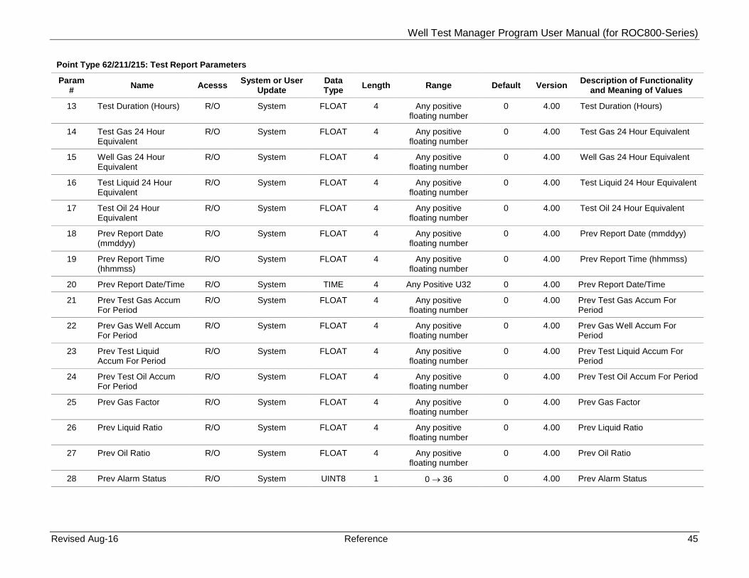
4.1 Point Type 62/211/215: Test Report Parameters
Point type 62/211/215 contains the parameters for the configuration of the test report of the program. The program supports up to 64 logicals of point type 62, up to 32 logicals of point type 211, and 11 logicals of point type 215.
Point Type 62/211/215: Test Report Parameters
Param # Name Acesss System or User
Update Data Type Length Range Default Version Description of Functionality
and Meaning of Values
0 Report Tag R/O System AC 10 Alpha Numeric Well 1 to 64
4.00 Report Tag
1 Report Date (mmddy) R/O System FLOAT 4 Any positive floating number
0 4.00 Report Date
2 Report Time (hhmmss) R/O System FLOAT 4 Any positive floating number
0 4.00 Report Time
3 Report Date/Time R/O System TIME 4 Any positive U32 0 4.00 Report Date/Time (Seconds elapsed since 1/01/1970 UTC)
4 Test Gas Accum For Period
R/O System FLOAT 4 Any positive floating number
0 4.00 Test Gas Accum For Period
5 Well Gas Accum For Period
R/O System FLOAT 4 Any positive floating number
0 4.00 Well Gas Accum For Period
6 Test Liquid Accum For Period
R/O System FLOAT 4 Any positive floating number
0 4.00 Test Liquid Accum For Period
7 Test Oil Accum For Period
R/O System FLOAT 4 Any positive floating number
0 4.00 Test Oil Accum For Period
8 Gas Factor R/O System FLOAT 4 Any positive floating number
0 4.00 Gas Factor
9 Liquid Ratio R/O System FLOAT 4 Any positive floating number
0 4.00 Liquid Ratio
10 Oil Ratio R/O System FLOAT 4 Any positive floating number
0 4.00 Oil Ratio
11 Alarm Status R/O System UINT8 1 0 → 36 0 4.00 Alarm Status
12 Test Verification R/O System UINT8 1 0 → 2 0 4.00 Test Verification Type: 0 = None 1 = Test Accepted 2 = Test Rejected
Well Test Manager Program User Manual (for ROC800-Series)
Revised Aug-16 Reference 45
Point Type 62/211/215: Test Report Parameters
Param # Name Acesss System or User
Update Data Type Length Range Default Version Description of Functionality
and Meaning of Values
13 Test Duration (Hours) R/O System FLOAT 4 Any positive floating number
0 4.00 Test Duration (Hours)
14 Test Gas 24 Hour Equivalent
R/O System FLOAT 4 Any positive floating number
0 4.00 Test Gas 24 Hour Equivalent
15 Well Gas 24 Hour Equivalent
R/O System FLOAT 4 Any positive floating number
0 4.00 Well Gas 24 Hour Equivalent
16 Test Liquid 24 Hour Equivalent
R/O System FLOAT 4 Any positive floating number
0 4.00 Test Liquid 24 Hour Equivalent
17 Test Oil 24 Hour Equivalent
R/O System FLOAT 4 Any positive floating number
0 4.00 Test Oil 24 Hour Equivalent
18 Prev Report Date (mmddyy)
R/O System FLOAT 4 Any positive floating number
0 4.00 Prev Report Date (mmddyy)
19 Prev Report Time (hhmmss)
R/O System FLOAT 4 Any positive floating number
0 4.00 Prev Report Time (hhmmss)
20 Prev Report Date/Time R/O System TIME 4 Any Positive U32 0 4.00 Prev Report Date/Time
21 Prev Test Gas Accum For Period
R/O System FLOAT 4 Any positive floating number
0 4.00 Prev Test Gas Accum For Period
22 Prev Gas Well Accum For Period
R/O System FLOAT 4 Any positive floating number
0 4.00 Prev Gas Well Accum For Period
23 Prev Test Liquid Accum For Period
R/O System FLOAT 4 Any positive floating number
0 4.00 Prev Test Liquid Accum For Period
24 Prev Test Oil Accum For Period
R/O System FLOAT 4 Any positive floating number
0 4.00 Prev Test Oil Accum For Period
25 Prev Gas Factor R/O System FLOAT 4 Any positive floating number
0 4.00 Prev Gas Factor
26 Prev Liquid Ratio R/O System FLOAT 4 Any positive floating number
0 4.00 Prev Liquid Ratio
27 Prev Oil Ratio R/O System FLOAT 4 Any positive floating number
0 4.00 Prev Oil Ratio
28 Prev Alarm Status R/O System UINT8 1 0 → 36 0 4.00 Prev Alarm Status

Well Test Manager Program User Manual (for ROC800-Series)
46 Reference Revised Aug-16
Point Type 62/211/215: Test Report Parameters
Param # Name Acesss System or User
Update Data Type Length Range Default Version Description of Functionality
and Meaning of Values
29 Prev Test Verification Type
R/O System UINT8 1 0 → 2 0 4.00 Prev Test Verification Type: 0 = None 1 = Test Accepted 2 = Test Rejected
30 Prev Test Duration (Hours)
R/O System FLOAT 4 Any positive floating number
0 4.00 Prev Test Duration (Hours)
31 Prev Test Gas 24 Hour Equivalent
R/O System FLOAT 4 Any positive floating number
0 4.00 Prev Test Gas 24 Hour Equivalent
32 Prev Well Gas 24 Hour Equivalent
R/O System FLOAT 4 Any positive floating number
0 4.00 Prev Well Gas 24 Hour Equivalent
33 Prev Test Liquid 24 Hour Equivalent
R/O System FLOAT 4 Any positive floating number
0 4.00 Prev Test Liquid 24 Hour Equivalent
34 Prev Test Oil 24 Hour Equivalent
R/O System FLOAT 4 Any positive floating number
0 4.00 Prev Test Oil 24 Hour Equivalent
35 Clear Test Report R/W Both UINT8 1 0 → 1 0 4.00 Clear Test Report: 0 = Reset 1 = Clear
36 Tubing Average R/O System FLOAT 4 Any positive floating number
0 4.04 Tubing Average
37 Casing Average R/O System FLOAT 4 Any positive floating number
0 4.04 Casing Average
38 Choke Position Average
R/O System FLOAT 4 Any positive floating number
0 4.04 Choke Position Average
39 Prev Tubing Average R/O System FLOAT 4 Any positive floating number
0 4.04 Prev Tubing Average
40 Prev Casing Average R/O System FLOAT 4 Any positive floating number
0 4.04 Prev Casing Average
41 Prev Choke Position Average
R/O System FLOAT 4 Any positive floating number
0 4.04 Prev Choke Position Average

Well Test Manager Program User Manual (for ROC800-Series)
Revised Aug-16 Reference 47
4.2 Point Type 63/212/216: Well Test Setup Parameters
Point type 63/212/216 contains the parameters for the configuration of the well test setup of the program. This is the global program setup. There will be 1 logical instance of this for point type 64, or 1 logical instance for point type 212, or 1 logical instance for point type 216.
Point Type 63/212/216: Well Test Setup Parameters
Param # Name Acesss System or User
Update Data Type Length Range Default Version Description of Functionality
and Meaning of Values
0 Test Mode R/W Both UINT8 1 0 → 5 0 2.07 Test Mode: 0 = Shut All 1 = Enable Test 2 = Manual Valves Enable 3 = Hold Test 4 = No Test 5 = Test One Cycle
1 Cycle Mode R/O System UINT8 1 0 → 14 0 2.05 Cycle Code: 0 = No Wells Enabled 1 = All Valves Shut 2 = All Wells To Sales 3 = Hold Test At Current Well 4 = Waiting Manual Start 5 = Select A Well 6 = Selected Well Disabled 7 = Permissive Fail 8 = Pre Purge 9 = Test In Progress 10 = Post Purge 11 = Outlet Valve Open 12 = Outlet Valve Open Delay 13 = Outlet Valve Close Delay 14 = Outlet Valve Close
2 Test Period/Timed Stop Preset (Hours)
R/W User FLOAT 4 Any positive floating number
24 1.00 Test Period/Timed Stop Preset (Hours)
3 Test Period/Timed Stop Timer (Hours)
R/O System FLOAT 4 Any positive floating number
0 1.00 Test Period/Timed Stop Timer (Hours)
4 Post Purge Time Preset (Hours)
R/W User FLOAT 4 Any positive floating number
0 1.00 Post Purge Time Preset (Hours)
5 Post Purge Timer (Hours)
R/O System FLOAT 4 Any positive floating number
0 1.00 Post Purge Timer (Hours)

Well Test Manager Program User Manual (for ROC800-Series)
48 Reference Revised Aug-16
Point Type 63/212/216: Well Test Setup Parameters
Param # Name Acesss System or User
Update Data Type Length Range Default Version Description of Functionality
and Meaning of Values
6 Current Tested Well R/W Both UINT8 1 0 → 63, 255 1 2.01 Current Test Well: 0 - 63 = Current 255 = Select A Well
7 Test Gas Flow R/O System FLOAT 4 Any positive floating number
0 1.00 Test Gas Flow
8 Test Gas Accum For Period
R/O System FLOAT 4 Any positive floating number
0 1.00 Test Gas Accum For Period
9 Test Gas Last Total For Period
R/O System FLOAT 4 Any positive floating number
0 1.00 Test Gas Last Total For Period
10 Test Gas Flow TLP R/W User TLP 3 0,0,0 1.00 Test Gas Flow TLP
11 Gas Correction Factor Minimum
R/W User FLOAT 4 Any positive floating number
0 1.00 Gas Correction Factor Minimum
12 Apply Gas Quality To Test Meter
R/W User UINT8 1 0 → 1 1 1.00 Apply Gas Quality To Test Meter
13 Test Liquid Flow R/O System FLOAT 4 Any positive floating number
0 1.00 Test Liquid Flow
14 Test Liquid Accum For Period
R/O System FLOAT 4 Any positive floating number
0 1.00 Test Liquid Accum For Period
15 Test Liquid Last Total For Period
R/O System FLOAT 4 Any positive floating number
0 1.00 Test Liquid Last Total For Period
16 Test Liquid TLP R/W User TLP 3 0,0,0 1.00 Test Liquid TLP
17 Action On Failure R/W UINT8 1 0 → 8 0 2.07 Action On Failure: 0 = None 1 = Skip Failed Well; Close
Sales & Test 2 = Skip Failed Well; Open
Sales & Close Test 3 = Shut All Valves 4 = All Sales Open 5 = Skip Failed Well; Open
Sales & Close Test w/Sequencing
6 = All Sales Open w/Sequencing
7 = Abort Test 8 = Stop Test

Well Test Manager Program User Manual (for ROC800-Series)
Revised Aug-16 Reference 49
Point Type 63/212/216: Well Test Setup Parameters
Param # Name Acesss System or User
Update Data Type Length Range Default Version Description of Functionality
and Meaning of Values
18 Valve Travel Time (Sec)
R/W User FLOAT 4 Any positive floating number
0 1.00 Valve Travel Time (Sec)
19 Valve Comparison State
R/W User UINT8 1 0 → 1 0 1.00 Valve Comparison State: 0 = Direct 1 = Reversed
20 Solenoid DO Invert R/W User UINT8 1 0 → 1 0 1.00 Solenoid DO Invert: 0 = Normal 1 = Reversed
21 Reserved
22 Min Period Before New Factor Applied
R/W User FLOAT 4 Any positive floating number
0 1.01 Min Period Before New Factor Applied
23 Test Oil Flow R/O System FLOAT 4 Any positive floating number
0 1.01 Test Oil Flow
24 Test Oil Accum For Period
R/O System FLOAT 4 Any positive floating number
0 1.01 Test Oil Accum For Period
25 Test Oil Last Total For Period
R/O System FLOAT 4 Any positive floating number
0 1.01 Test Oil Last Total For Period
26 Test Oil TLP R/W User TLP 3 0,0,0 1.01 Test Oil TLP
27 Use Sales Total For Virtual Calcs
R/W User UINT8 1 0 → 1 0 1.01 Use Sales Total For Virtual Well Calcs: 0 = No Sales Meter 1 = Use Sales Meter
28 Sales Total Gas Flow R/O System FLOAT 4 Any positive floating number
0 1.01 Sales Total Gas Flow
29 Sales Total Gas Accum For Period
R/O System FLOAT 4 Any positive floating number
0 1.01 Sales Total Gas Accum For Period
30 Sales Total Gas Last Total For Period
R/O System FLOAT 4 Any positive floating number
0 1.01 Sales Total Gas Last Total For Period
31 Sales Total Gas Flow TLP
R/W User TLP 3 0,0,0 1.01 Sales Total Gas Flow TLP
32 Sales Total Gas Today’s Last
R/O System FLT 4 Any positive floating number
0 1.01 Sales Total Gas Today’s Last

Well Test Manager Program User Manual (for ROC800-Series)
50 Reference Revised Aug-16
Point Type 63/212/216: Well Test Setup Parameters
Param # Name Acesss System or User
Update Data Type Length Range Default Version Description of Functionality
and Meaning of Values
33 Log Gas Correction Factor Events
R/W User UINT8 1 0 → 1 1 1.01 Log Gas Correction Factor To Event Log: 0 = Events Not Logged 1 = Log Events
34 Normalize Non-Test Wells
R/W User UINT8 1 0 → 1 1 1.01 Normalize Non-Test Wells: 0 = No Normalization 1 = Normalize
35 Cycle Start TLP R/W User TLP 3 0,0,0 2.00 Cycle Start TLP
36 Cycle Start Value R/W Both UINT8 1 0 → 2 0 2.00 Cycle Start Value: 0 = Cycle Stop 1 = Cycle Start 2 = Cycle Abort
37 Timed Stop After Manual Start
R/W User UINT8 1 0 → 1 0 2.00 Timed Stop After Manual Start: 0 = No Timed Stop 1 = Stop After Timer
38 Test Meter Low Flow Check Delay Preset (Seconds)
R/W User FLOAT 4 Any positive floating number
0.1 2.00 Test Meter Low Flow Check Delay Preset (Seconds)
39 Test Meter Low Flow Between Cycles
R/W User FLOAT 4 Any positive floating number
1 2.00 Test Meter Low Flow Between Cycles
40 Tank Oil Vapor Total R/O System FLOAT 4 Any positive floating number
0 2.00 Tank Oil Vapor Total
41 Tank Oil Vapor Factor R/W User FLOAT 4 Any positive floating number
0.25 2.00 Tank Oil Vapor Factor
42 External Total Accum Rollover
R/W User U32 4 0 → 4294967295 1000000 2.00 External Total Accum Rollover
43 Oil Total Accum Value R/W Both FLOAT 4 Any positive floating number
0 2.00 Oil Total Accum Value
44 Oil Last Total Accum Value
R/O System FLOAT 4 Any positive floating number
0 2.00 Oil Last Total Accum Value
45 H2O Total Accum Value
R/W Both FLOAT 4 Any positive floating number
0 2.00 H2O Total Accum Value
46 H2O Last Total Accum Value
R/O System FLOAT 4 Any positive floating number
0 2.00 H2O Last Total Accum Value

Well Test Manager Program User Manual (for ROC800-Series)
Revised Aug-16 Reference 51
Point Type 63/212/216: Well Test Setup Parameters
Param # Name Acesss System or User
Update Data Type Length Range Default Version Description of Functionality
and Meaning of Values
47 Cycle Step R/O System UINT8 1 0 → 7 0 2.07 Cycle Step
48 Log To Alarm Log R/W User UINT8 1 0 → 7 0 2.00 Log To Alarm Log: 0 = No 1 = Log Alarms
49 Cycle Message Text R/O System AC 20 Alpha Numeric 2.00 Cycle Message Text
50 Force Well Selection After Stop
R/W User UINT8 1 0 → 1 0 2.01 Force Well Selection After Stop: 0 = Normal Well Select 1 = Force Well Select
51 Current Tested Well Text
R/O System AC 10 Alpha Numeric 2.02 Current Tested Well Text
52 Tank Oil Total TLP R/W User TLP 3 0,0,0 2.03 Tank Oil Total TLP
53 Tank Oil Period Accum R/O System FLOAT 4 Any positive floating number
0 2.03 Tank Oil Period Accum
54 Tank Oil Total Accum Value
R/O System UINT32 4 0 2.03 Tank Oil Total Accum Value
55 Tank Oil Last Total Accum Value
R/O System UINT32 4 0 2.03 Tank Oil Last Total Accum Value
56 Tank Water Total TLP R/W User TLP 3 0,0,0 2.00 Tank Water Total TLP
57 Tank Water Period Accum
R/O System FLOAT 4 Any positive floating number
0 2.03 Tank Water Period Accum
58 Tank Water Total Accum Value
R/O System UINT32 4 0 2.03 Tank Water Total Accum Value
59 Tank Water Total Accum Value
R/O System UINT32 4 0 2.03 Tank Water Total Accum Value
60 Cycle Abort TLP R/W User TLP 3 0,0,0 2.03 Cycle Abort TLP
61 Cycle Stop TLP R/W User TLP 3 0,0,0 2.03 Cycle Stop TLP
62 PrePurge Timer (Hours)
R/O System FLOAT 4 Any positive floating number
0 2.05 PrePurge Timer (Hours)

Well Test Manager Program User Manual (for ROC800-Series)
52 Reference Revised Aug-16
Point Type 63/212/216: Well Test Setup Parameters
Param # Name Acesss System or User
Update Data Type Length Range Default Version Description of Functionality
and Meaning of Values
63 Test Validation Mode R/W User U8 1 0 → 3 0 2.05 Validation Mode: 0 = No Validation 1 = Accept Test Only 2 = Accept Or Reject Test 3 = Auto Accept
64 Gas Factor Tolerance R/W User FLOAT 4 0 → 1.0 0 2.05 Gas Factor Tolerance
65 Oil Ratio Tolerance R/W User FLOAT 4 0 → 1.0 0 2.05 Oil Ratio Tolerance
66 Water Ratio Tolerance R/W User FLOAT 4 0 → 1.0 0 2.05 Water Ratio Tolerance
67 Momentary Valve Time On Delay
R/W User FLOAT 4 Any positive floating number
0 2.05 Momentary Valve Time On Delay
68 Alarm Code R/O System UINT8 1 0 → 142 0 2.05 Alarm Code: 0 = No Alarms 1 = No License Found 2 = Shutdown Well 1 3 = Shutdown Well 2 4 = Shutdown Well 3 5 = Shutdown Well 4 6 = Shutdown Well 5 7 = Shutdown Well 6 8 = Shutdown Well 7 9 = Shutdown Well 8 10 = Shutdown Well 9 11 = Shutdown Well 10 12 = Shutdown Well 11 13 = Illegal Valve State Well 1 14 = Illegal Valve State Well 2 15 = Illegal Valve State Well 3 16 = Illegal Valve State Well 4 17 = Illegal Valve State Well 5 18 = Illegal Valve State Well 6 19 = Illegal Valve State Well 7 20 = Illegal Valve State Well 8 21 = Illegal Valve State Well 9 22 = Illegal Valve State Well 10 23 = Illegal Valve State Well 11 24 = Short Cycle Error 25 = Minimum Gas Factor 26 = Gas Factor > 1 27 = Gas Factor Tolerance

Well Test Manager Program User Manual (for ROC800-Series)
Revised Aug-16 Reference 53
Point Type 63/212/216: Well Test Setup Parameters
Param # Name Acesss System or User
Update Data Type Length Range Default Version Description of Functionality
and Meaning of Values 28 = Water Ratio Tolerance 29 = Oil Ratio Tolerance 30 = Test Meter Flow Error 31 = Zero Test Gas Accum 32 = Zero Sales Gas Accum 33 = Zero Well Gas Accum 34 = Last Test Aborted 35 = DI Permissive Fail 36 = Outlet Valve Fail 37 = Shutdown Well 12 38 = Shutdown Well 13 39 = Shutdown Well 14 40 = Shutdown Well 15 41 = Shutdown Well 16 42 = Shutdown Well 17 43 = Shutdown Well 18 44 = Shutdown Well 19 45 = Shutdown Well 20 46 = Shutdown Well 21 47 = Shutdown Well 22 48 = Shutdown Well 23 49 = Shutdown Well 24 50 = Shutdown Well 25 51 = Shutdown Well 26 52 = Shutdown Well 27 53 = Shutdown Well 28 54 = Shutdown Well 29 55 = Shutdown Well 30 56 = Shutdown Well 31 57 = Shutdown Well 32 58 = Shutdown Well 33 59 = Shutdown Well 34 60 = Shutdown Well 35 61 = Shutdown Well 36 62 = Shutdown Well 37 63 = Shutdown Well 38 64 = Shutdown Well 39 65 = Shutdown Well 40 66 = Shutdown Well 41 67 = Shutdown Well 42 68 = Shutdown Well 43 69 = Shutdown Well 44 70 = Shutdown Well 45

Well Test Manager Program User Manual (for ROC800-Series)
54 Reference Revised Aug-16
Point Type 63/212/216: Well Test Setup Parameters
Param # Name Acesss System or User
Update Data Type Length Range Default Version Description of Functionality
and Meaning of Values 71 = Shutdown Well 46 72 = Shutdown Well 47 73 = Shutdown Well 48 74 = Shutdown Well 49 75 = Shutdown Well 50 76 = Shutdown Well 51 77 = Shutdown Well 52 78 = Shutdown Well 53 79 = Shutdown Well 54 80 = Shutdown Well 55 81 = Shutdown Well 56 82 = Shutdown Well 57 83 = Shutdown Well 58 84 = Shutdown Well 59 85 = Shutdown Well 60 86 = Shutdown Well 61 87 = Shutdown Well 62 88 = Shutdown Well 63 89 = Shutdown Well 64 90 = Valve State Well 12 91 = Valve State Well 13 92 = Valve State Well 14 93 = Valve State Well 15 94 = Valve State Well 16 95 = Valve State Well 17 96 = Valve State Well 18 97 = Valve State Well 19 98 = Valve State Well 20 99 = Valve State Well 21 100 = Valve State Well 22 101 = Valve State Well 23 102 = Valve State Well 24 103 = Valve State Well 25 104 = Valve State Well 26 105 = Valve State Well 27 106 = Valve State Well 28 107 = Valve State Well 29 108 = Valve State Well 30 109 = Valve State Well 31 110 = Valve State Well 32 111 = Valve State Well 33 112 = Valve State Well 34 113 = Valve State Well 35

Well Test Manager Program User Manual (for ROC800-Series)
Revised Aug-16 Reference 55
Point Type 63/212/216: Well Test Setup Parameters
Param # Name Acesss System or User
Update Data Type Length Range Default Version Description of Functionality
and Meaning of Values 114 = Valve State Well 36 115 = Valve State Well 37 116 = Valve State Well 38 117 = Valve State Well 39 118 = Valve State Well 40 119 = Valve State Well 41 120 = Valve State Well 42 121 = Valve State Well 43 122 = Valve State Well 44 123 = Valve State Well 45 124 = Valve State Well 46 125 = Valve State Well 47 126 = Valve State Well 48 127 = Valve State Well 49 128 = Valve State Well 50 129 = Valve State Well 51 130 = Valve State Well 52 131 = Valve State Well 53 132 = Valve State Well 54 133 = Valve State Well 55 134 = Valve State Well 56 135 = Valve State Well 57 136 = Valve State Well 58 137 = Valve State Well 59 138 = Valve State Well 60 139 = Valve State Well 61 140 = Valve State Well 62 141 = Valve State Well 63 142 = Valve State Well 64
69 Alarm Message R/O System AC 20 Alpha Numeric 2.05 Alarm Message
70 Well Count Acknowledge
R/O System UINT8 1 0 → 11 0 2.05 Well Count Acknowledge
71 Water Entrained In Oil Percent
R/W User FLOAT 4 Any positive floating number
0 2.05 Water Entrained In Oil Percent
72 Tank Oil Deduct TLP R/W User TLP 3 0,0,0 2.05 Tank Oil Deduct TLP
73 Tank Oil Deduct Accum
R/O System FLOAT 4 Any positive floating number
0 2.05 Tank Oil Deduct Accum
74 Tank Oil Deduct R/O System FLOAT 4 Any positive floating number
0 2.05 Tank Oil Deduct

Well Test Manager Program User Manual (for ROC800-Series)
56 Reference Revised Aug-16
Point Type 63/212/216: Well Test Setup Parameters
Param # Name Acesss System or User
Update Data Type Length Range Default Version Description of Functionality
and Meaning of Values
75 Tank Oil Deduct Last R/O System FLOAT 4 Any positive floating number
0 2.05 Tank Oil Deduct Last
76 Tank Water Deduct TLP
R/W User TLP 3 0,0,0 2.05 Tank Water Deduct TLP
77 Tank Water Deduct Accum
R/O System FLOAT 4 Any positive floating number
0 2.05 Tank Water Deduct Accum
78 Tank Water Deduct R/O System FLOAT 4 Any positive floating number
0 2.05 Tank Water Deduct
79 Tank Water Deduct Last
R/O System FLOAT 4 Any positive floating number
0 2.05 Tank Water Deduct Last
80 Valve DI Mode R/W User UINT8 1 0 → 2 0 2.07 Valve DI Mode: 0 = DI Monitor Only 1 = Valve State Failure 2 = Start/Test Permissives
81 Previous Tested Well R/O System UINT8 1 0 → 11 0 2.07 Previous Tested Well
82 Sales Gas Total Accum Value
R/O System FLOAT 4 Any positive floating number
0 2.10 Sales Gas Total Accum Value
83 Test Separator Outlet Sole Open TLP
R/W User TLP 3 0,0,0 2.11 Test Separator Outlet Sole Open TLP
84 Test Separator Outlet Open Value
R/O System UINT8 1 0 → 1 0 2.11 Test Separator Outlet Open Value
85 Test Separator Outlet Sole Close TLP
R/W User TLP 3 0,0,0 2.11 Test Separator Outlet Sole Close TLP
86 Test Separator Outlet Close Value
R/O System UINT8 1 0 → 1 0 2.11 Test Separator Outlet Close Value
87 Test Separator Outlet Open Limit Switch TLP
R/W User TLP 3 0,0,0 2.11 Test Separator Outlet Open Limit Switch TLP
88 Test Separator Outlet Open Limit Switch Value
R/O System UINT8 1 0 → 1 0 2.11 Test Separator Outlet Open Limit Switch Value
89 Test Separator Outlet Close Limit Switch TLP
R/W User TLP 3 0,0,0 2.11 Test Separator Outlet Close Limit Switch TLP

Well Test Manager Program User Manual (for ROC800-Series)
Revised Aug-16 Reference 57
Point Type 63/212/216: Well Test Setup Parameters
Param # Name Acesss System or User
Update Data Type Length Range Default Version Description of Functionality
and Meaning of Values
90 Test Separator Outlet Close Limit Switch Value
R/O System UINT8 1 0 → 1 0 2.11 Test Separator Outlet Close Limit Switch Value
91 Test Separator Outlet Valve Delay Preset (Sec)
R/W User FLOAT 4 Any positive floating number
0 2.11 Test Separator Outlet Valve Delay Preset (Sec)
92 Test Separator Outlet Valve Timer (Sec)
R/O System FLOAT 4 Any positive floating number
0 2.11 Test Separator Outlet Valve Timer (Sec)
93 Max Logicals R/O System UINT8 1 11, 32, 64 4.00 Max Logicals
94 Insert Well Once R/O Both UINT8 1 0 → 2 0 4.04 Insert Well Once: 0 = None 1 = Insert Next 2 = Restore Well Order
(System Only) 95 Well To Insert R/W User UINT8 1 0 → 10, 31, 63 1 4.04 Well To Insert
96 Well To Restore R/O System UINT8 1 0 → 10, 31, 63 1 4.04 Well To Restore
97 Use Individual Well Test Times
R/W User UINT8 1 0 → 1 0 4.04 Use Individual Well Test Times
98 Held Test Report R/O System UINT8 1 0 → 11, 32, 64 0 4.10 Held Test Report
99 Held Test Report Date R/O System FLOAT 4 Any positive floating number
0 4.10 Held Test Report Date
100 Held Test Report Time R/O System FLOAT 4 Any positive floating number
0 4.10 Held Test Report Time
101 Held Test Report Date/Time
R/O System FLOAT 4 0 4.10 Held Test Report Date/Time (Seconds elapsed since 1/01/1970 UTC)
102 Held Test Gas Accum For Period
R/O System FLOAT 4 Any positive floating number
0 4.10 Held Test Gas Accum For Period
103 Held Well Gas Accum For Period
R/O System FLOAT 4 Any positive floating number
0 4.10 Held Well Gas Accum For Period
104 Held Test Liquid Accum For Period
R/O System FLOAT 4 Any positive floating number
0 4.10 Held Test Liquid Accum For Period

Well Test Manager Program User Manual (for ROC800-Series)
58 Reference Revised Aug-16
Point Type 63/212/216: Well Test Setup Parameters
Param # Name Acesss System or User
Update Data Type Length Range Default Version Description of Functionality
and Meaning of Values
105 Held Test Oil Accum For Period
R/O System FLOAT 4 Any positive floating number
0 4.10 Held Test Oil Accum For Period
106 Held Gas Factor R/O System FLOAT 4 Any positive floating number
0 4.10 Held Gas Factor
107 Held Liquid Ratio R/O System FLOAT 4 Any positive floating number
0 4.10 Held Liquid Ratio
108 Held Oil Ratio R/O System FLOAT 4 Any positive floating number
0 4.10 Held Oil Ratio
109 Held Alarm Status R/O System U8 1 0 4.10 Held Alarm Status
110 Held Test Duration (Hrs)
R/O System FLOAT 4 Any positive floating number
0 4.10 Held Test Duration (Hrs)
111 Held Test Gas 24 Hr Equivalent
R/O System FLOAT 4 Any positive floating number
0 4.10 Held Test Gas 24 Hr Equivalent
112 Held Well Gas 24 Hr Equivalent
R/O System FLOAT 4 Any positive floating number
0 4.10 Held Well Gas 24 Hr Equivalent
113 Held Test Liquid 24 Hr Equivalent
R/O System FLOAT 4 Any positive floating number
0 4.10 Held Test Liquid 24 Hr Equivalent
114 Held Test Oil 24 Hr Equivalent
R/O System FLOAT 4 Any positive floating number
0 4.10 Held Test Oil 24 Hr Equivalent
115 Held Tubing Press Avg R/O System FLOAT 4 Any positive floating number
0 4.10 Held Tubing Press Avg
116 Held Casing Press Avg R/O System FLOAT 4 Any positive floating number
0 4.10 Held Casing Press Avg
117 Held Choke Position Avg
R/O System FLOAT 4 Any positive floating number
0 4.10 Held Choke Position Avg
118 Data Update Rate R/W User UINT8 1 1, 2, 4, 6, 8, 10 1 4.11 Data Update Rate
119 Watchdog Timer R/O System UINT16 2 0 → 65,535 0 4.13.00 Shows the current value of the user program watchdog timer. This value increments by a value of 1 for each execution cycle of the user program.
120 Test Gas Meas Type R/W User UINT8 1 0 → 1 0 4.13.00 Describes the behavior of the parameter being selected for the test gas meter input. When

Well Test Manager Program User Manual (for ROC800-Series)
Revised Aug-16 Reference 59
Point Type 63/212/216: Well Test Setup Parameters
Param # Name Acesss System or User
Update Data Type Length Range Default Version Description of Functionality
and Meaning of Values accumulation is selected, it is expected that an incrementing accumulator parameter is selected. When flowrate is selected, it is expected that a live flowrate which drops to 0 when there is no flow is selected.
0 = Accumulated
1 = Flowrate
121 Sales Gas Meas Type R/W User UINT8 1 0 → 1 0 4.13.00 Describes the behavior of the parameter being selected for the sales gas meter input. When accumulation is selected, it is expected that an incrementing accumulator parameter is selected. When flowrate is selected, it is expected that a live flowrate which drops to 0 when there is no flow is selected.
0 = Accumulated
1 = Flowrate
122 Test Water Meas Type R/W User UINT8 1 0 → 1 0 4.13.00 Describes the behavior of the parameter being selected for the test water meter input. When accumulation is selected, it is expected that an incrementing accumulator parameter is selected. When flowrate is selected, it is expected that a live flowrate which drops to 0 when there is no flow is selected.
0 = Accumulated 1 = Flowrate
123 Test Oil Meas Type R/W User UINT8 1 0 → 1 0 4.13.00 Describes the behavior of the parameter being selected for

Well Test Manager Program User Manual (for ROC800-Series)
60 Reference Revised Aug-16
Point Type 63/212/216: Well Test Setup Parameters
Param # Name Acesss System or User
Update Data Type Length Range Default Version Description of Functionality
and Meaning of Values the test oil meter input. When accumulation is selected, it is expected that an incrementing accumulator parameter is selected. When flowrate is selected, it is expected that a live flowrate which drops to 0 when there is no flow is selected.
0 = Accumulated 1 = Flowrate
124 PrePurge Timer Start R/O System UINT32 4 0 → 4294967295 0 4.13.00 The starting time of the pre-purge process. This allows the current value of the timer to be saved correctly following a system or program restart.
125 Test Timer Start R/O System UINT32 4 0 → 4294967295 0 4.13.00 The starting time of the well test process. This allows the current value of the timer to be saved correctly following a system or program restart.
126 Post Purge Timer Start R/O System UINT32 4 0 → 4294967295 0 4.13.00 The starting time of the post-purge process. This allows the current value of the timer to be saved correctly following a system or program restart.
127 Valve Timer Start R/O System UINT32 4 0 → 4294967295 0 4.13.00 The starting time of the valve process. This allows the current value of the timer to be saved correctly following a system or program restart.
128 Valve Seq Timer Start R/O System UINT32 4 0 → 4294967295 0 4.13.00 The starting time of the valve sequence process. This allows the current value of the timer to be saved correctly following a system or program restart.

Well Test Manager Program User Manual (for ROC800-Series)
Revised Aug-16 Reference 61
4.3 Point Type 64/213/217: Wells
Point type 64/213/217 contains the parameters for the configuration of the wells of the program. The program supports up to 64 logicals of point type 64, up to 32 logicals of point type 213, and 11 logicals of point type 217.
Point Type 64/213/217: Well Test Setup Parameters
Param # Name Acesss System or User
Update Data Type Length Range Default Version Description of Functionality
and Meaning of Values
0 Well Tag R/W User AC 10 Alpha Numeric Well 1 to 64
1.00 Test Well Tag
1 Well Enable R/W Both UINT8 1 0 → 1 0 1.00 Scan Enable: 0 = Disable 1 = Enable
2 Well Flow R/O System FLOAT 4 Any positive floating number
0 1.00 Well Flow Composite
3 Well Gas Accum For Period
R/O System FLOAT 4 Any positive floating number
0 1.00 Well Gas Accum For Period
4 Well Gas Last Total For Period
R/O System FLOAT 4 Any positive floating number
0 1.00 Well Gas Last Total For Period
5 Well Flow TLP R/W User TLP 3 0,0,0 1.00 Well Flow TLP
6 Well Gas Correction Factor
R/W Both FLOAT 4 Any positive floating number
1 1.00 Well Gas Correction Factor
7 Well Liquid Ratio R/W Both FLOAT 4 Any positive floating number
1 1.00 Well Liquid Ratio
8 Test Solenoid TLP R/W User TLP 3 0,0,0 1.00 Test Solenoid TLP
9 Test Solenoid Value R/O System UINT8 1 0 → 1 0 1.00 Test Solenoid Value
10 Test Valve Open Limit Switch TLP
R/W User TLP 3 0,0,0 1.00 Test Valve Open Limit Switch TLP
11 Test Valve Open Limit Switch Value
R/W User UINT8 1 0 → 1 0 2.00 Test Valve Open Limit Switch Value
12 Test Valve Close Limit Switch TLP
R/W User TLP 3 0,0,0 1.00 Test Valve Close Limit Switch TLP
13 Test Valve Close Limit Switch Value
R/W User UINT8 1 0 → 1 0 2.00 Test Valve Close Limit Switch Value
14 Sales Solenoid TLP R/W User TLP 3 0,0,0 1.00 Sales Solenoid TLP

Well Test Manager Program User Manual (for ROC800-Series)
62 Reference Revised Aug-16
Point Type 64/213/217: Well Test Setup Parameters
Param # Name Acesss System or User
Update Data Type Length Range Default Version Description of Functionality
and Meaning of Values
15 Sales Solenoid Value R/O System UINT8 1 0 → 1 0 1.00 Sales Solenoid Value
16 Sales Valve Open Limit Switch TLP
R/W User TLP 3 0,0,0 1.00 Sales Valve Open Limit Switch TLP
17 Sales Valve Open Limit Switch Value
R/W User UINT8 1 0 → 1 0 1.00 Sales Valve Open Limit Switch Value
18 Sales Valve Close Limit Switch TLP
R/W User TLP 3 0,0,0 1.00 Sales Valve Close Limit Switch TLP
19 Sales Valve Close Limit Switch Value
R/W User UINT8 1 0 → 1 0 1.00 Sales Valve Close Limit Switch Value
20 Test Report Accum Softpoint Table
R/W User UINT8 1 0 → 32 1 1.00 Test Report Accum Softpoint Table: 0 = Disable 1 - 32 = Softpoint Table Selection
21 Well Shutdown Trip R/W User UINT8 1 0 → 1 0 1.00 Well Shutdown Trip: 0 = Normal 1 = Shutdown 0 = Shutdown (Inverted) 1 = Normal (Inverted)
22 Well Shutdown TLP R/W User TLP 3 0,0,0 1.00 Well Shutdown TLP
23 Well Oil Ratio R/W Both FLOAT 4 Any positive floating number
0 1.01 Well Oil Ratio
24 Well Total Accum R/O System FLOAT 4 Any positive floating number
0 1.01 Well Virtual Total Accum
25 Well Today’s Accum R/O System FLOAT 4 Any positive floating number
0 1.01 Well Virtual Today’s Accum
26 Well Yesterday’s Accum
R/O System FLOAT 4 Any positive floating number
0 1.01 Well Virtual Yesterday’s Accum
27 Oil Accum For Period R/O System FLOAT 4 Any positive floating number
0 2.00 Oil Accum For Period
28 Oil Total Accum R/O System FLOAT 4 Any positive floating number
0 2.00 Oil Total Accum
29 Oil Today’s Accum R/O System FLOAT 4 Any positive floating number
0 2.00 Oil Today’s Accum

Well Test Manager Program User Manual (for ROC800-Series)
Revised Aug-16 Reference 63
Point Type 64/213/217: Well Test Setup Parameters
Param # Name Acesss System or User
Update Data Type Length Range Default Version Description of Functionality
and Meaning of Values
30 Oil Yesterday’s Accum R/O System FLOAT 4 Any positive floating number
0 2.00 Oil Yesterday’s Accum
31 H2O Accum For Period R/O System FLOAT 4 Any positive floating number
0 2.00 H2O Accum For Period
32 H2O Total Accum R/O System FLOAT 4 Any positive floating number
0 2.00 H2O Total Accum
33 H2O Today’s Accum R/O System FLOAT 4 Any positive floating number
0 2.00 H2O Today’s Accum
34 H2O Yesterday’s Accum
R/O System FLOAT 4 Any positive floating number
0 2.00 H2O Yesterday’s Accum
35 PrePurge Timer Preset (Hours)
R/W User FLOAT 4 Any positive floating number
0 2.05 PrePurge Timer Preset (Hours)
36 Last Test Date R/O System FLOAT 4 Any positive floating number
0 2.05 Last Test Date
37 Last Test Time R/O System FLOAT 4 Any positive floating number
0 2.05 Last Test Time
38 Last Test Accum For Period
R/O System FLOAT 4 Any positive floating number
0 2.05 Last Test Accum For Period
39 Last Well Accum For Period
R/O System FLOAT 4 Any positive floating number
0 2.05 Last Well Accum For Period
40 Last Liquid Accum For Period
R/O System FLOAT 4 Any positive floating number
0 2.05 Last Liquid Accum For Period
41 Last Oil Accum For Period
R/O System FLOAT 4 Any positive floating number
0 2.05 Last Oil Accum For Period
42 Last Well Gas Correction Factor
R/O System FLOAT 4 Any positive floating number
1 2.05 Last Well Gas Correction Factor
43 Last Well Liquid Ratio R/O System FLOAT 4 Any positive floating number
1 2.05 Last Well Liquid Ratio
44 Last Well Oil Ratio R/O System FLOAT 4 Any positive floating number
1 2.05 Last Well Oil Ratio
45 Last Alarm Status R/O System UINT8 1 0 → 35 0 2.05 Last Alarm Status
46 Test Close Solenoid TLP
R/W User TLP 3 0,0,0 2.05 Test Close Solenoid TLP
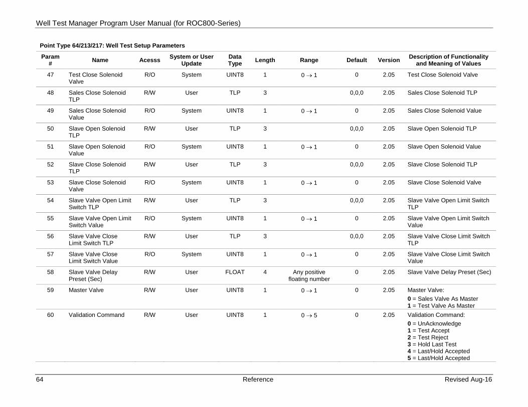
Well Test Manager Program User Manual (for ROC800-Series)
64 Reference Revised Aug-16
Point Type 64/213/217: Well Test Setup Parameters
Param # Name Acesss System or User
Update Data Type Length Range Default Version Description of Functionality
and Meaning of Values
47 Test Close Solenoid Valve
R/O System UINT8 1 0 → 1 0 2.05 Test Close Solenoid Valve
48 Sales Close Solenoid TLP
R/W User TLP 3 0,0,0 2.05 Sales Close Solenoid TLP
49 Sales Close Solenoid Value
R/O System UINT8 1 0 → 1 0 2.05 Sales Close Solenoid Value
50 Slave Open Solenoid TLP
R/W User TLP 3 0,0,0 2.05 Slave Open Solenoid TLP
51 Slave Open Solenoid Value
R/O System UINT8 1 0 → 1 0 2.05 Slave Open Solenoid Value
52 Slave Close Solenoid TLP
R/W User TLP 3 0,0,0 2.05 Slave Close Solenoid TLP
53 Slave Close Solenoid Valve
R/O System UINT8 1 0 → 1 0 2.05 Slave Close Solenoid Valve
54 Slave Valve Open Limit Switch TLP
R/W User TLP 3 0,0,0 2.05 Slave Valve Open Limit Switch TLP
55 Slave Valve Open Limit Switch Value
R/O System UINT8 1 0 → 1 0 2.05 Slave Valve Open Limit Switch Value
56 Slave Valve Close Limit Switch TLP
R/W User TLP 3 0,0,0 2.05 Slave Valve Close Limit Switch TLP
57 Slave Valve Close Limit Switch Value
R/O System UINT8 1 0 → 1 0 2.05 Slave Valve Close Limit Switch Value
58 Slave Valve Delay Preset (Sec)
R/W User FLOAT 4 Any positive floating number
0 2.05 Slave Valve Delay Preset (Sec)
59 Master Valve R/W User UINT8 1 0 → 1 0 2.05 Master Valve: 0 = Sales Valve As Master 1 = Test Valve As Master
60 Validation Command R/W User UINT8 1 0 → 5 0 2.05 Validation Command: 0 = UnAcknowledge 1 = Test Accept 2 = Test Reject 3 = Hold Last Test 4 = Last/Hold Accepted 5 = Last/Hold Accepted

Well Test Manager Program User Manual (for ROC800-Series)
Revised Aug-16 Reference 65
Point Type 64/213/217: Well Test Setup Parameters
Param # Name Acesss System or User
Update Data Type Length Range Default Version Description of Functionality
and Meaning of Values
61 Well Tested R/O System UINT8 1 0 → 1 0 2.07 Well Tested (Test Once Cycle): 0 = Untested 1 = Tested
62 Well Shutdown Trip Invert
R/W User UINT8 1 0 → 1 0 2.09 Well Shutdown Trip Invert: 0 = Untested 1 = Tested
63 Test Duration Hours R/O System FLOAT 4 Any Positive Float Point Number
0 2.09 Test Duration Hours
64 Last Test Duration Hours
R/O System FLOAT 4 Any Positive Float Point Number
0 2.09 Last Test Duration Hours
65 Tubing Average TLP R/W User TLP 3 0,0,0 2.09 Tubing Average TLP
66 Tubing Average Value R/O System FLOAT 4 Any Positive Float Point Number
0 2.09 Tubing Average Value
67 Casing Average TLP R/W User TLP 3 0,0,0 2.09 Casing Average TLP
68 Casing Average Value R/O System FLOAT 4 Any Positive Float Point Number
0 2.09 Casing Average Value
69 Choke Position Average TLP
R/W User FLOAT 3 0,0,0 2.09 Choke Position Average TLP
70 Choke Position Average Value
R/O System FLOAT 4 Any Positive Float Point Number
0 2.09 Choke Position Average Value
71 Last Test Gas 24 Hour Equivalent
R/O System FLOAT 4 Any Positive Float Point Number
0 4.00 Last Test Gas 24 Hour Equivalent
72 Last Well Gas 24 Hour Equivalent
R/O System FLOAT 4 Any Positive Float Point Number
0 4.00 Last Well Gas 24 Hour Equivalent
73 Last Test Liquid 24 Hour Equivalent
R/O System FLOAT 4 Any Positive Float Point Number
0 4.00 Last Test Liquid 24 Hour Equivalent
74 Last Test Oil 24 Hour Equivalent
R/O System FLOAT 4 Any Positive Float Point Number
0 4.00 Last Test Oil 24 Hour Equivalent
75 Well Test Order R/W User U8 1 0 → 255 0 → 11, 32, 64
4.04 Well Test Order
76 Test Period/Timed Stop Preset (Hours)
R/W User FLOAT 4 Any Positive Float Point Number
24 4.04 Test Period/Timed Stop Preset (Hours)
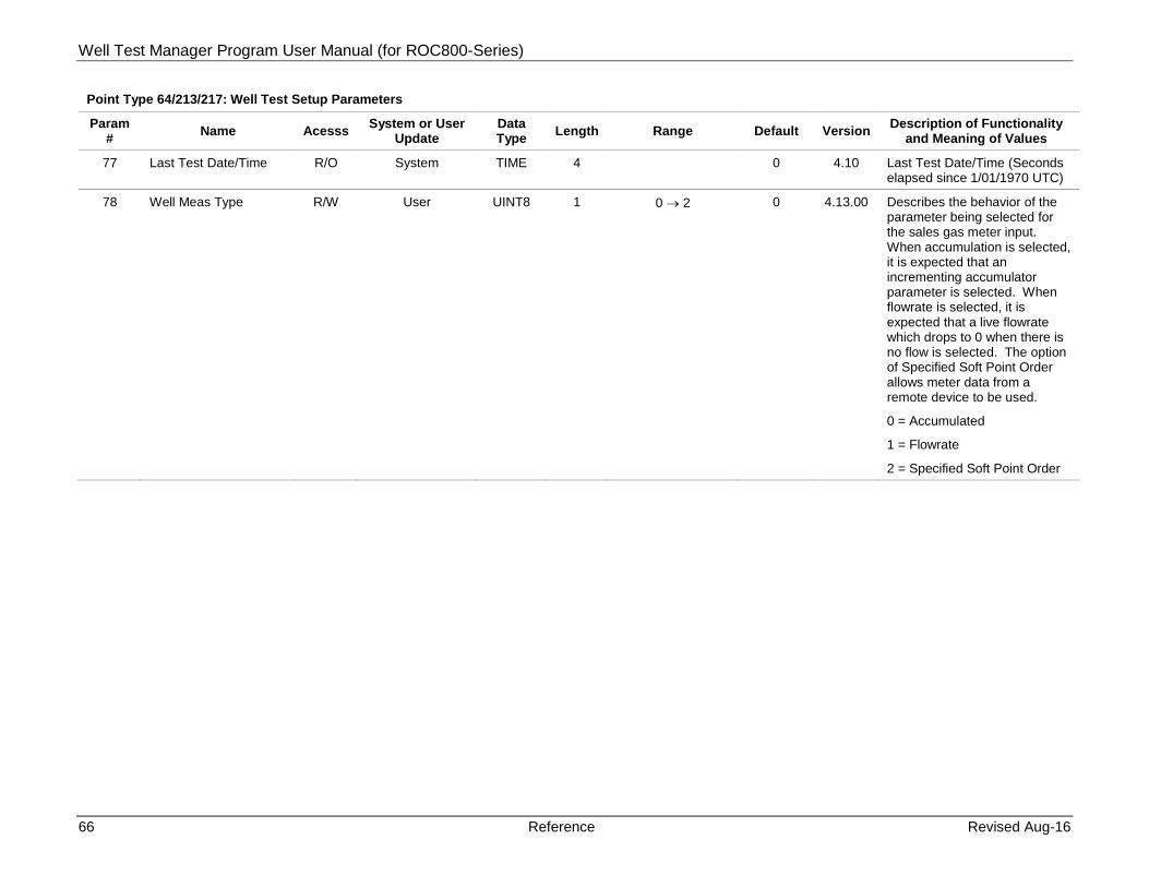
Well Test Manager Program User Manual (for ROC800-Series)
66 Reference Revised Aug-16
Point Type 64/213/217: Well Test Setup Parameters
Param # Name Acesss System or User
Update Data Type Length Range Default Version Description of Functionality
and Meaning of Values
77 Last Test Date/Time R/O System TIME 4 0 4.10 Last Test Date/Time (Seconds elapsed since 1/01/1970 UTC)
78 Well Meas Type R/W User UINT8 1 0 → 2 0 4.13.00 Describes the behavior of the parameter being selected for the sales gas meter input. When accumulation is selected, it is expected that an incrementing accumulator parameter is selected. When flowrate is selected, it is expected that a live flowrate which drops to 0 when there is no flow is selected. The option of Specified Soft Point Order allows meter data from a remote device to be used.
0 = Accumulated
1 = Flowrate
2 = Specified Soft Point Order

Well Test Manager Program User Manual (for ROC800-Series)
Revised Aug-16 Reference 67
[This page is intentionally left blank.]

Well Test Manager Program User Manual (for ROC800-Series)
For customer service and technical support, visit www.EmersonProcess.com/Remote/Support.
Global Headquarters, North America, and Latin America:
Emerson Process Management Remote Automation Solutions 6005 Rogerdale Road Houston, TX 77072 U.S.A. T +1 281 879 2699 | F +1 281 988 4445 www.EmersonProcess.com/Remote
© 2015–2016 Remote Automation Solutions, a business unit of Emerson Process Management. All rights reserved.
This publication is for informational purposes only. While every effort has been made to ensure accuracy, this publication shall not be read to include any warranty or guarantee, express or implied, including as regards the products or services described or their use or applicability. Remote Automation Solutions (RAS) reserves the right to modify or improve the designs or specifications of its products at any time without notice. All sales are governed by RAS terms and conditions which are available upon request. RAS accepts no responsibility for proper selection, use or maintenance of any product, which remains solely with the purchaser and/or end-user.
Europe: Emerson Process Management Remote Automation Solutions Unit 8, Waterfront Business Park Dudley Road, Brierley Hill Dudley UK DY5 1LX T +44 1384 487200 | F +44 1384 487258
Middle East/Africa: Emerson Process Management Remote Automation Solutions Emerson FZE P.O. Box 17033 Jebel Ali Free Zone – South 2 Dubai U.A.E. T +971 4 8118100 | F +971 4 8865465
Asia-Pacific: Emerson Process Management Remote Automation Solutions 1 Pandan Crescent Singapore 128461 T +65 6777 8211| F +65 6777 0947
Remote Automation Solutions