wellbore schematics
DESCRIPTION
Wellbore SchematicsTRANSCRIPT
Wellbore Schematics
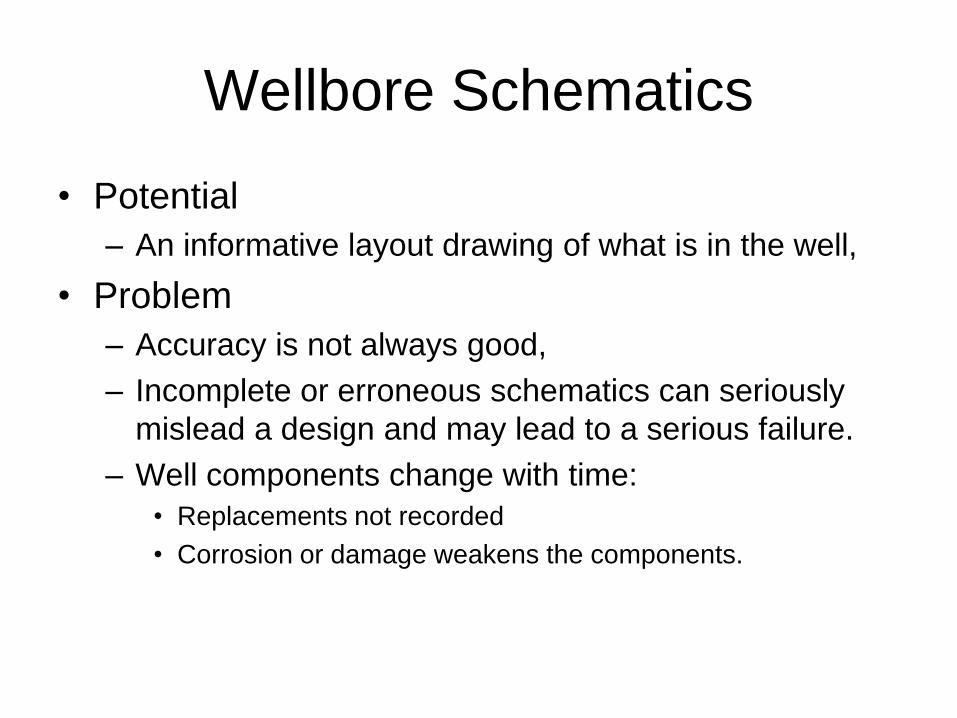
• Potential
– An informative layout drawing of what is in the well,
• Problem
– Accuracy is not always good,
– Incomplete or erroneous schematics can seriously
mislead a design and may lead to a serious failure.
– Well components change with time:
• Replacements not recorded
• Corrosion or damage weakens the components.
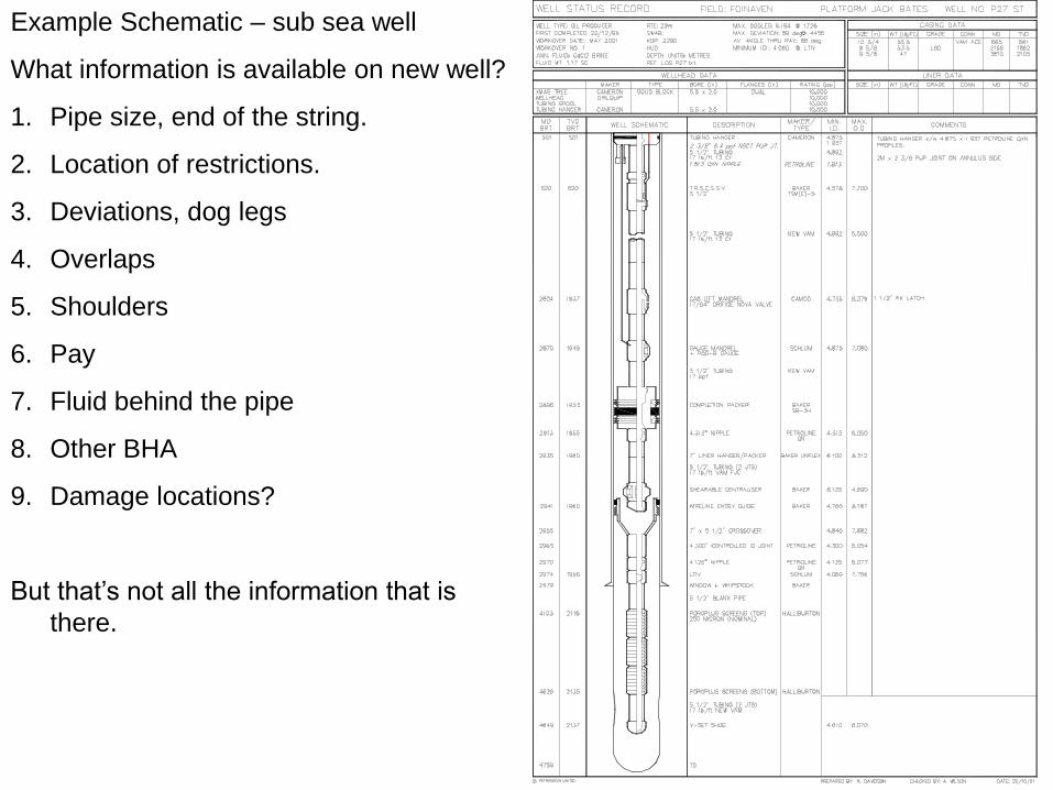
Example Schematic – sub sea well
What information is available on new well?
1. Pipe size, end of the string.
2. Location of restrictions.
3. Deviations, dog legs
4. Overlaps
5. Shoulders
6. Pay
7. Fluid behind the pipe
8. Other BHA
9. Damage locations?
But that’s not all the information that is
there.
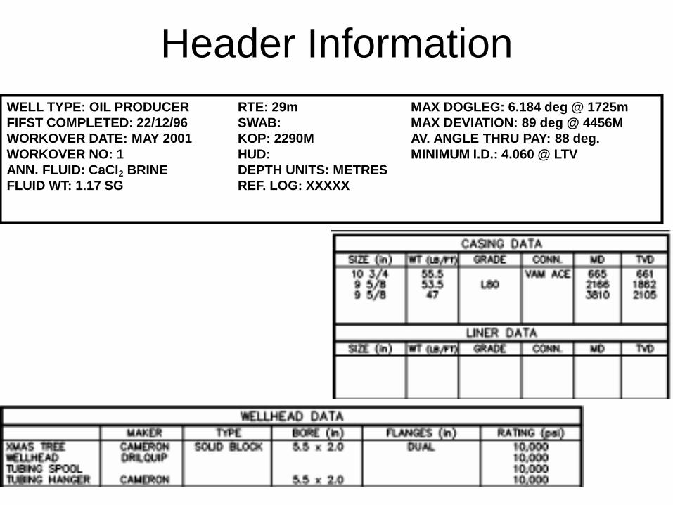
Header Information
WELL TYPE: OIL PRODUCER RTE: 29m MAX DOGLEG: 6.184 deg @ 1725m
FIFST COMPLETED: 22/12/96 SWAB: MAX DEVIATION: 89 deg @ 4456M
WORKOVER DATE: MAY 2001 KOP: 2290M AV. ANGLE THRU PAY: 88 deg.
WORKOVER NO: 1 HUD: MINIMUM I.D.: 4.060 @ LTV
ANN. FLUID: CaCl2 BRINE DEPTH UNITS: METRES
FLUID WT: 1.17 SG REF. LOG: XXXXX
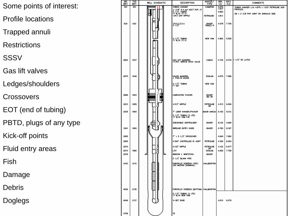
Some points of interest:
Profile locations
Trapped annuli
Restrictions
SSSV
Gas lift valves
Ledges/shoulders
Crossovers
EOT (end of tubing)
PBTD, plugs of any type
Kick-off points
Fluid entry areas
Fish
Damage
Debris
Doglegs
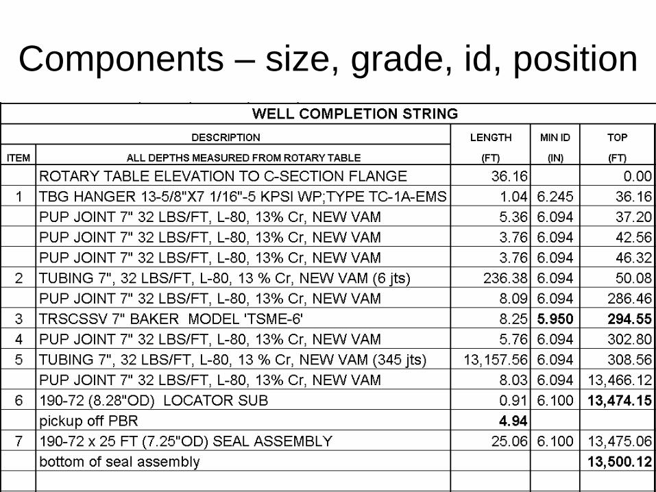
Components – size, grade, id, position


Mixed equipment
• What is the pressure rating of this well?
Sometimes components are mixed in a well, often with the aid of crossover pieces to
adapt fittings of different pressure ratings. The pressure rating is set by the current
strength of the lowest strength piece. Actual testing is required to determine the level of
working pressure. When damage is known to have occurred, the components must be
tested, isolated or replaced.
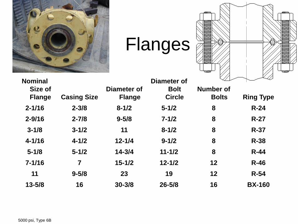
Flanges
Nominal
Size of
Flange Casing Size
Diameter of
Flange
Diameter of
Bolt
Circle
Number of
Bolts Ring Type
2-1/16 2-3/8 8-1/2 5-1/2 8 R-24
2-9/16 2-7/8 9-5/8 7-1/2 8 R-27
3-1/8 3-1/2 11 8-1/2 8 R-37
4-1/16 4-1/2 12-1/4 9-1/2 8 R-38
5-1/8 5-1/2 14-3/4 11-1/2 8 R-44
7-1/16 7 15-1/2 12-1/2 12 R-46
11 9-5/8 23 19 12 R-54
13-5/8 16 30-3/8 26-5/8 16 BX-160
5000 psi, Type 6B

Valves
Above and Below: Gate valve
seals and bar – common in
wellheads.
Right top: plug
valve – common
in surface
treating “iron”
Right center:
dowhole flapper
valve.
Right lower:
butterfly valve
common on
tanks.
Note: open a valve fully (count
the turns) and close it fully (also
count turns) – throttling flow with
a valve will lead to erosion.

Profiles

Pay Interval Schematic
1. Where are the fluid entry points
1. From the wellbore
2. From the reservoir.
2. Will the interval between the sceens pack
during gravel packing?
3. Will ECP’s inflate? How long is the slide?
How rough? What deviation? What fluid is
use to inflate? What is the stability and
permeability of the set point?

Limited Schematics
Artists renditions – too much missing.
Problems in a deviated well arise around kickoff points (window
debris, sharp edges, doglegs), build angle, junction isolation quality
and changes in angle along the horizontal plane.
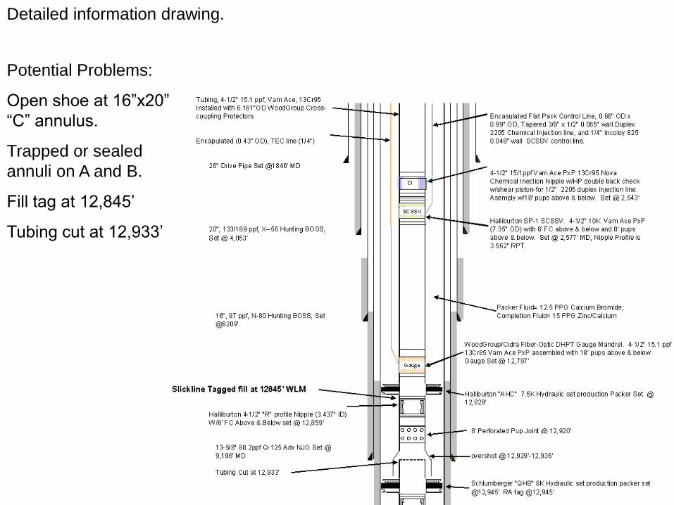
Detailed information drawing.
Potential Problems:
Open shoe at 16”x20”
“C” annulus.
Trapped or sealed
annuli on A and B.
Fill tag at 12,845’
Tubing cut at 12,933’
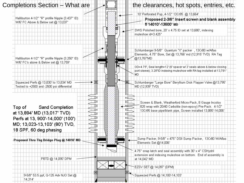
Completions Section – What are the clearances, hot spots, entries, etc.
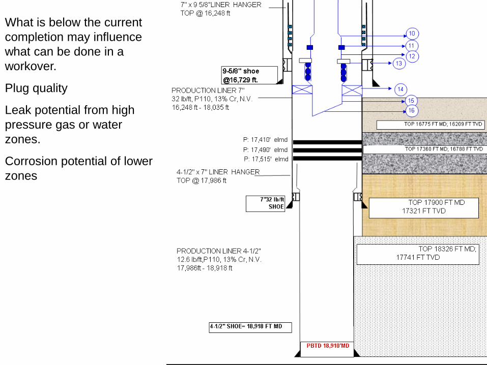
What is below the current
completion may influence
what can be done in a
workover.
Plug quality
Leak potential from high
pressure gas or water
zones.
Corrosion potential of lower
zones
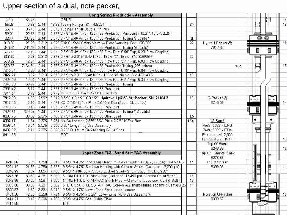
Upper section of a dual, note packer,
15
15a
15a

Bottom zone of a dual completion with sand control. Note clearances, screen location with respect
to pay, isolation potential, method of stacking the completion, and opportunities for problems.
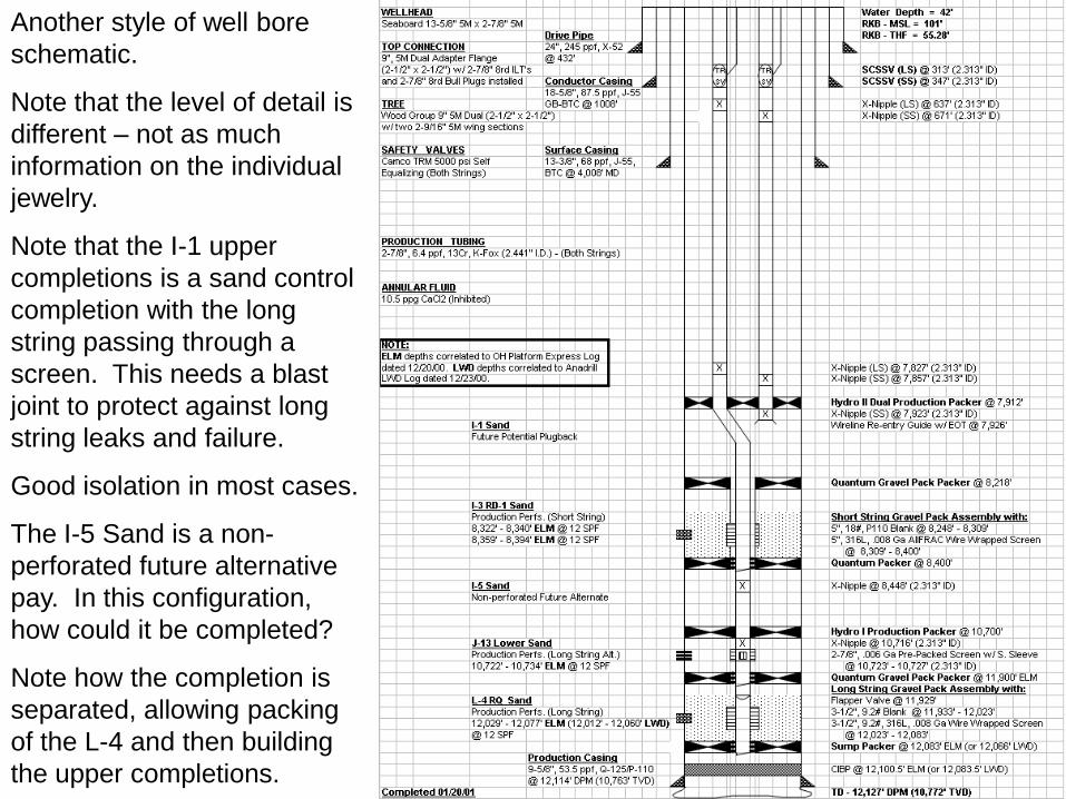
Another style of well bore
schematic.
Note that the level of detail is
different – not as much
information on the individual
jewelry.
Note that the I-1 upper
completions is a sand control
completion with the long
string passing through a
screen. This needs a blast
joint to protect against long
string leaks and failure.
Good isolation in most cases.
The I-5 Sand is a non-
perforated future alternative
pay. In this configuration,
how could it be completed?
Note how the completion is
separated, allowing packing
of the L-4 and then building
the upper completions.

Gas Lift Valve Locations:
Depth
Size?
Dummied or Active?
Condition?
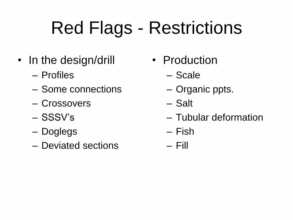
Red Flags - Restrictions
• In the design/drill
– Profiles
– Some connections
– Crossovers
– SSSV’s
– Doglegs
– Deviated sections
• Production
– Scale
– Organic ppts.
– Salt
– Tubular deformation
– Fish
– Fill
Workover Concerns
• Tubing end – entry of tool strings
• Latching plugs and fish
– Deviated set points
– Fill
• Swell of elastomers on plugs
• Swell and bow in fired perforating guns
• Overlap sections for perforating
• Liner tops (leaks)
• How to circulate out the back side.

Common Mistakes and Errors
• Schematic not current: – Last redesign, workover, failure not listed.
– Corrosion, fill, collapses, or fish not listed.
– Does pipe/wellhead need to be derated?
– Deviation shortens tool length that will run through the bend.
• So, how do you know what’s there? – Drift / tag, bailer, dummy tool runs, impression blocks,
camera…
– Talk to the field and last engineer who had the well.