wells screens and gravel packs - ohio department...
TRANSCRIPT

M I D W E S T C O N F E R E N C E 2 0 1 3
WELLS SCREENS AND
GRAVEL PACKS
WELL SCREENS
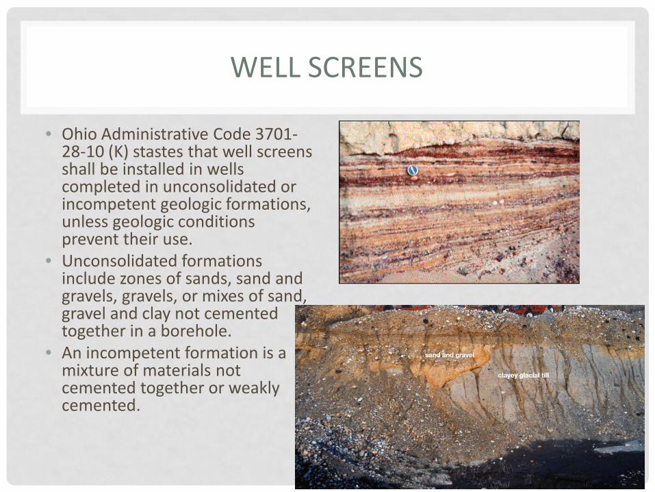
• Ohio Administrative Code 3701-28-10 (K) stastes that well screens shall be installed in wells completed in unconsolidated or incompetent geologic formations, unless geologic conditions prevent their use.
• Unconsolidated formations include zones of sands, sand and gravels, gravels, or mixes of sand, gravel and clay not cemented together in a borehole.
• An incompetent formation is a mixture of materials not cemented together or weakly cemented.

WELL SCREEN INSTALLED IN AN UNCONSOLIDATED GEOLOGIC FORMATION

GEOLOGIC CONDITIONS THAT MIGHT PREVENT THE USE OF A WELL SCREEN
• There are three formation conditions generally acknowledged as being very difficult in which to set a screen: • very thin (less than 1-2 feet thick) • unconsolidated formations, • 2) the presence of "heaving" sand, or • 3) the presence of very large cobbles (loose rocks 2.5 to 10.1 inches in
diameter) or boulders (loose rocks having at least one lineal dimension greater than 10.1 inches).
• Over the years, contractors experiencing these types of geologic formations have developed alternate construction practices to address such borehole conditions. P
• Remember that other rules require a well be properly developed and turbidity in the well minimized, requirements applicable to all wells and geologic formations.
• If sand and silt size particles are mixed in with large cobbles and boulders the formation will still need to be screened to prevent the entrance of sand and silt into the well.
• The contractor should note this information on the well log
WELL SCREENS
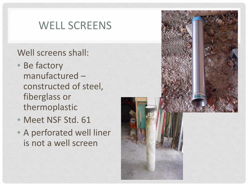
Well screens shall: • Be factory
manufactured – constructed of steel, fiberglass or thermoplastic
• Meet NSF Std. 61 • A perforated well liner
is not a well screen

WELL SCREENS
• Have uniform openings and be of sufficient length to provide a 0.1 feet per second entrance velocity under normal pumping conditions.
• Slot sizes properly sized to facilitate proper well maintenance and development, and minimize entrance of fine materials.
• With the exception of fiberglass casing, hand drilled holes, hand cut slots, torch cut or burned slots are not permitted.

WELL SCREENS
• Screens shall provide sufficient column and collapse strength to withstand installation and borehole pressures.
WELL SCREENS
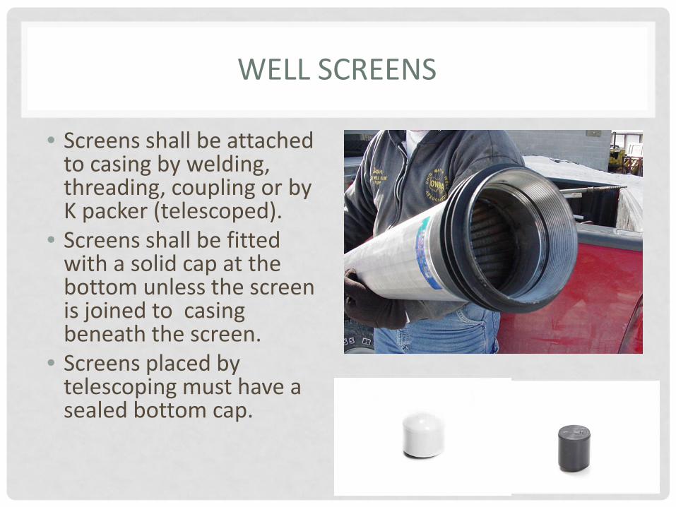
• Screens shall be attached to casing by welding, threading, coupling or by K packer (telescoped).
• Screens shall be fitted with a solid cap at the bottom unless the screen is joined to casing beneath the screen.
• Screens placed by telescoping must have a sealed bottom cap.

WELL SCREENS
• Shale traps may not be substituted for K packers. • Well screens shall not be installed <10 feet from the
natural ground surface.

HOW TO RECORD MULTIPLE WELL SCREENS ON THE WELL LOG
• The Water Mapping and Technical Services Section, Division of Soil and Water Resources, Ohio Department of Natural Resources (ODNR) has established a method for well drillers to record the placement of multiple well screens separated by solid casing in a well. The method also addresses how a driller is to record the use of screens with different slot sizes.
• The following information should be recorded on the Well Log: • Screen length = the combined length of all the screens • Screen slot size = the most predominant size used or smallest size being
used • Screen set from = the shallowest depth below the surface and
Screen set to = the lowest (deepest) depth below the surface

EXAMPLE
• For a well with two screens, one 3 foot, 0.040 slot screen and one 3 foot, 0.050 slot screen placed at 40 feet and 60 feet respectively, the contractor should record: • Screen length = 6 feet (the two 3-foot sections) • Screen slot size = 0.040 (the smallest size screen) • Screen set from = 40 to 63 feet (shallowest depth and deepest depth)
• In the Well Log’s “Comments on water quality, quantity and well construction” box, which allows up to 500 characters, the contractor would explain that a 3 foot, 40 slot screen was installed from 40-43 feet and that a 3 foot, 50 slot screen was installed from 60-63 feet.
• ODNR staff ask drillers using paper Well Logs, which do not have a “Comments” box, to simply write the depths and sizes of all screens in the “Screen” section under “Construction Details” of the Well Log form, separating each piece of information with a slash. The above example would be recorded as such: “6-feet/0.040/40-60 feet.” The information could also be written at the bottom of the “Drilling Log*” section.

FILTER PACKS AND FORMATION STABILIZERS
Filter packs and formation stabilizers installed in an annular space shall be:
- 95% siliceous (quartz, sand, flint, agate, and many other minerals) in composition and free of foreign matter.
- Properly sized, washed and completely disinfected using liquid sodium hypochlorite prior to placement in the well
- stored to prevent contamination prior to placement

FILTER PACKS
Filter packs or formation stabilizers to be placed in accordance with the following: • Placed adjacent to well screen • Extend a maximum of 2 feet
above a screen in wells equal to or smaller than 6 inches in diameter and a maximum of 4 feet above wells larger than 6 inches in diameter.
• Shall not extend less than 10 feet from the natural ground surface.

FILTER PACK/FORMATION STABILIZER
• For wells larger than 20 inches in diameter, filter pack/formation stabilizers shall not be greater than 6 inches per side for wells less than 30 feet deep and shall be no greater than 4 inches per side for wells greater than 30 feet deep.
• Filter packs/formation stabilizers are not to be placed inside casing or liner pipe.
• Except in flowing well conditions, all drilling fluids are to be flushed from the annular space before the filter pack/formation stabilizers are placed.
WELL DEVELOPMENT
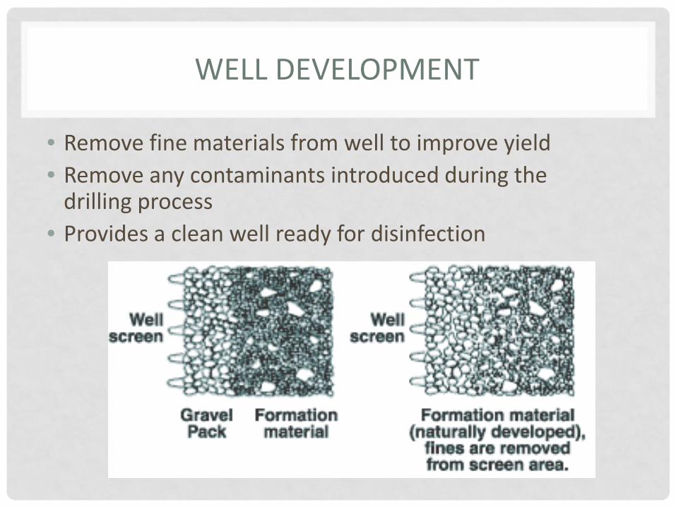
• Remove fine materials from well to improve yield • Remove any contaminants introduced during the
drilling process • Provides a clean well ready for disinfection


OTHER ISSUES
• During the development process fine materials and small pieces of gravel are removed from the formation
• Material is redistributed around the well screen • Some natural collapse of the formation or gravel pack may
occur during devlopment • Contractors often place extra gravel pack in the annular space
to account for this collapse, and may record this volume/height of gravel on the well log
• Contractors should be recording the finished height of the gravel pack AFTER development.
OTHER ISSUES
• When formations stabilizers extend greater distances above the well screen, then the annular space is filled with formation stabilizer and there is no room for the placement of grout in the annular space.
• OAC Rule 3701-28-10(E)(1) states that all annular space is to be filled with grout from the bottom of the annular space or top of any formation stabilizer, filter/gravel pack to the ground surface.
• Large lengths of formation stabilizer in the borehole also allow water from different geologic zones to enter the well which can increase the drawdown in a well, or allow water of poor quality to enter the well.
HOW ARE FORMATION STABILIZERS TO BE USED WHEN THERE ARE MULTIPLE WELL SCREENS?
• There are several things to be considered when using multiple
screens in a well. • In wells where more than one screen is installed, rule OAC 3701-28-
10(E)(3) allows for the placement of formation stabilizer, filter/gravel pack in the annular space between the screens.
• In these cases the formation stabilizer, filter/gravel pack may extend more than two feet above the top of the deeper screen and still be in compliance.

QUESTIONS?