wemco® hydrogritter · diameter grit cyclone(s) per classifier. --for correct sizing of...
TRANSCRIPT

WEMCO® HYDROGRITTER P11-D207
Suggested Specification
1 © 2019 Trillium Pumps USA SLC LLC
PART 1 GENERAL
1.01 DESCRIPTION OF WORK
A. Furnish and install ____ degritting system(s), consisting of ____(qty.) ____-inch minimum diameter screw-type dewatering classifier, complete with ____(qty.) ____-inch minimum diameter grit cyclone(s) per classifier.
--For correct sizing of classifiers and cyclones, see “WEMCO Hydrogritter Sizing Worksheet”.--
Cyclone Size
6-inch (600LC) 10-inch (1000C)
15-inch (1500CA) 20-inch (2000CA)
1.02 QUALITY ASSURANCE
A. All degritting equipment furnished under this Section shall be of a design and manufacture
that has been used in similar applications and it shall be demonstrated to the satisfaction of the Owner that the quality is equal to equipment made by that manufacturer specifically named herein. Manufacturers shall provide evidence of at least five (5) installations in which identically sized equipment has provided satisfactory performance for a minimum of five (5) years in a similar application. No consideration will be given to individually sized equipment that has not been commercially available for at least five (5) years.
B. To insure a consistently high standard of quality, the manufacturer of this pumping equipment shall comply with the requirements of the ISO 9001 Quality System, and such compliance shall be verified by an independent certification agency approved by the International Organization for Standardization. Documentation shall be submitted for approval showing compliance with this requirement, and the equipment will not be released for shipment until approved.
C. The complete degritting system specified in this section shall be furnished by, and be the
product of, one manufacturer including the grit pump, cyclone, classifier and all specified accessories and appurtenances, to ensure compatibility, integrity of individual components and unit responsibility.
1.03 SUBMITTALS
A. Submit shop drawings and product data under provisions of Section ________.
B. Submit manufacturer’s installation instructions under provisions of Section ______.
C. The submittal data shall be prepared, in its entirety, by the equipment manufacturer. Shop drawings prepared by the manufacturer’s sales representative, fabrication shops, or other than the listed manufacturers will not be acceptable. No additions or modifications to the manufacturer’s submittal will be accepted, with the sole exception of a cover sheet provided
Classifier Screw Size 12-inch 18-inch 24-inch 30-inch

WEMCO® HYDROGRITTER P11-D207
Suggested Specification
2 © 2019 Trillium Pumps USA SLC LLC
by the manufacturer’s local Representative.
D. The classifier and cyclone operating parameters, i.e., cyclone feed rate, pressure and underflow and classifier pool area, weir length, screw speed, submergence, and slope, have been selected to avoid build-up of fine grit in the classifier tank, which will cause grit of the desired size to evade capture. Changes in any of these parameters will not be acceptable unless a detailed submittal showing calculations and operating data provides evidence that any such change will not affect the ability of the system to perform as specified.
1.04 OPERATION AND MAINTENANCE DATA
A. Submit operation and maintenance data under provisions of Section ______.
B. Include installation instructions, assembly views, lubrication instructions, and replacement
parts lists. 1.05 DELIVERY, STORAGE AND HANDLING
A. Deliver, store, handle and protect the equipment under provisions of Section ______.
1.06 SERVICES OF MANUFACTURER
A. Furnish the services of a representative of the degritting system manufacturer to assist in adjusting and mechanical testing of the equipment furnished, to supervise the initial operation, and to make final adjustments as may be necessary to assure the Owner that the degritting system is in satisfactory operating condition.
B. Furnish sufficient supervision, data, and information from the manufacturer to train operators in the proper operation and maintenance of the equipment furnished.
1.07 CONDITIONS OF SERVICE AND PERFORMANCE
A. Grit collector underflow shall be pumped to the grit cyclone(s). The cyclone(s) shall separate
inlet feed into two streams: overflow and underflow. The overflow shall include the majority of the liquid along with lighter organic materials which can then be piped downstream or back to the grit collector. The underflow shall be concentrated grit slurry which shall be directed into the grit classifier. The grit classifier shall further remove organic material and shall separate the grit for discharge into a grit disposal system.
B. Each cyclone shall be sized for an inlet feed of ____ gpm at a pressure of ____ psi. At the inlet feed conditions specified, each grit cyclone shall be capable of capturing 95 percent of the grit entering the inlet feed that is larger than 105 micron (150 mesh) and has a specific gravity of 2.65 or greater.
C. At the inlet feed conditions specified, each grit classifier shall be capable of removing 95 percent of 105 micron (150 mesh) and larger grit from the underflow of the cyclone(s).

WEMCO® HYDROGRITTER P11-D207
Suggested Specification
3 © 2019 Trillium Pumps USA SLC LLC
PART 2 PRODUCTS
2.01 CYCLONE
Cyclone Size # Conical sections
Cyclone inlet feed diameter
(inch)
Cyclone overflow
(inch) Apex diameter
(inch) Vortex finder
diameter (inch) 6-inch (600LC) 1 2.5 3 1.5 3
10-inch (1000C) 2 4 6 2 4 15-inch (1500CA) 2 6 8 3 6 20-inch (2000CA) 3 8 10 4.5 7.5
A. Each cyclone shall consist of a heavy-duty cast iron volute feed chamber with one fabricated
steel cylindrical section with ____ conical sections and two apex sections of aluminum to minimize overhung weight.
1. Each section of the cyclone shall be individually lined and protected from the high
velocity grit by a replaceable [Choose one - rubber or neoprene] liner. The cyclone shall be constructed so that any section of the liner can be replaced independently.
2. A hinge and quick disconnect clamp shall be provided between the apex assembly
and lower cone section to allow removal of material which may clog the apex, without disconnecting any piping on the cyclone itself. Cyclone designs that do not provide an equal or greater number of quick disconnect sections will not be accepted due to the decrease in operator access and safety in the event of a clog.
B. The inlet feed to the cyclone shall be ____-inch, the overflow ____-inch, with Victaulic
connections furnished by the cyclone manufacturer. Cast iron adaptor pieces will be provided with ANSI 125 lb. flat face flanges. The adaptor piece will be fitted with a cast iron elbow on the overflow so that the flange face will mate up with horizontal piping.
C. Each cyclone shall be supplied complete with a ____-inch apex.
D. The cyclone vortex finder shall be ____-inch diameter and made of Ni-Hard with a minimum hardness of 500 Brinell.
E. Each cyclone inlet feed shall be tapped for a 1" NPT gauge connection and a diaphragm-
protected pressure gauge shall be provided by the cyclone manufacturer.
F. The cyclone underflow shall feed into the classifier for washing and dewatering, and be sized so that the proper hydraulic loading is provided to the classifier.
G. The cyclone overflow will feed to piping furnished by the contractor which must be properly and adequately vented to prevent siphoning.
H. The cyclone manufacturer shall supply a fabricated [Choose one – steel, galvanized steel,
or 316 stainless steel] support to mount the supplied cyclones.
1. The cyclone shall be attached to a minimum 3/8 inch [Choose one – steel, galvanized steel, or 316 stainless steel] mounting plate, properly oriented such that the cyclone underflow discharges directly into the classifier feedbox.
WEMCO® HYDROGRITTER P11-D207
Suggested Specification
4 © 2019 Trillium Pumps USA SLC LLC
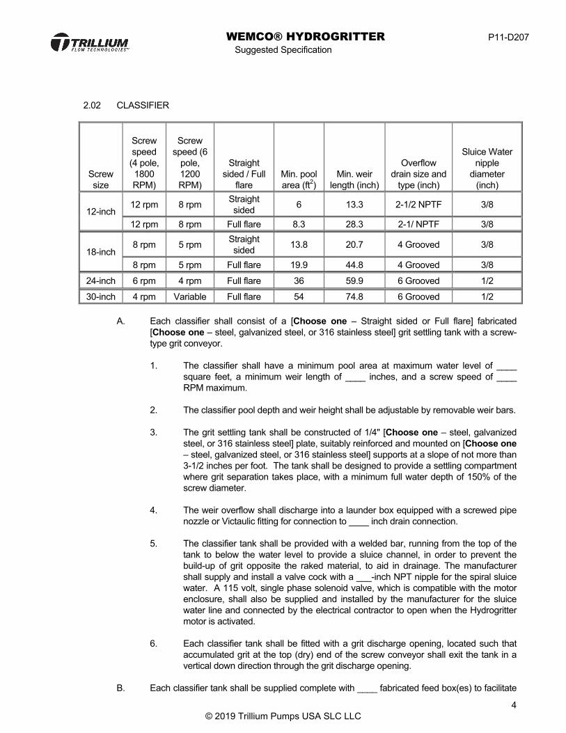
2.02 CLASSIFIER
Screw size
Screw speed (4 pole, 1800 RPM)
Screw
speed (6 pole, 1200 RPM)
Straight sided / Full
flare Min. pool area (ft2)
Min. weir length (inch)
Overflow drain size and
type (inch)
Sluice Water nipple
diameter (inch)
12-inch 12 rpm 8 rpm Straight
sided 6 13.3 2-1/2 NPTF 3/8
12 rpm 8 rpm Full flare 8.3 28.3 2-1/ NPTF 3/8
18-inch 8 rpm 5 rpm Straight
sided 13.8 20.7 4 Grooved 3/8
8 rpm 5 rpm Full flare 19.9 44.8 4 Grooved 3/8
24-inch 6 rpm 4 rpm Full flare 36 59.9 6 Grooved 1/2
30-inch 4 rpm Variable Full flare 54 74.8 6 Grooved 1/2
A. Each classifier shall consist of a [Choose one – Straight sided or Full flare] fabricated [Choose one – steel, galvanized steel, or 316 stainless steel] grit settling tank with a screw-type grit conveyor. 1. The classifier shall have a minimum pool area at maximum water level of ____
square feet, a minimum weir length of ____ inches, and a screw speed of ____ RPM maximum.
2. The classifier pool depth and weir height shall be adjustable by removable weir bars. 3. The grit settling tank shall be constructed of 1/4" [Choose one – steel, galvanized
steel, or 316 stainless steel] plate, suitably reinforced and mounted on [Choose one – steel, galvanized steel, or 316 stainless steel] supports at a slope of not more than 3-1/2 inches per foot. The tank shall be designed to provide a settling compartment where grit separation takes place, with a minimum full water depth of 150% of the screw diameter.
4. The weir overflow shall discharge into a launder box equipped with a screwed pipe
nozzle or Victaulic fitting for connection to ____ inch drain connection. 5. The classifier tank shall be provided with a welded bar, running from the top of the
tank to below the water level to provide a sluice channel, in order to prevent the build-up of grit opposite the raked material, to aid in drainage. The manufacturer shall supply and install a valve cock with a ___-inch NPT nipple for the spiral sluice water. A 115 volt, single phase solenoid valve, which is compatible with the motor enclosure, shall also be supplied and installed by the manufacturer for the sluice water line and connected by the electrical contractor to open when the Hydrogritter motor is activated.
6. Each classifier tank shall be fitted with a grit discharge opening, located such that
accumulated grit at the top (dry) end of the screw conveyor shall exit the tank in a vertical down direction through the grit discharge opening.
B. Each classifier tank shall be supplied complete with ____ fabricated feed box(es) to facilitate

WEMCO® HYDROGRITTER P11-D207
Suggested Specification
5 © 2019 Trillium Pumps USA SLC LLC
the introduction of underflow from the cyclone into the classifier.
C.
Screw size Number of feedboxes
(standard) Number of feedboxes
(option) 12-inch 1 2 18-inch 1 2 24-inch 2 As required 30-inch 2 As required
1. The feed box shall be reinforced minimum 12 gauge [Choose one – steel,
galvanized steel, or 316 stainless steel] plate, and shall be fitted with a wear protector, coated with ¼-inch thick neoprene to protect against abrasion, and to function as a splashguard. The wear protector and splashguard shall be internal to the feedbox such that no splashing will be allowed outside the feedbox. Radial flow diffusers shall not be acceptable.
2. The feed boxes shall have hinged covers, to provide for inspection of the cyclone
apexes without disturbing the cyclone piping or alignment. The hinged covers shall be provided with two snap buckles, one on each side, for quick release. The feedbox must allow the operator to easily view the discharge of the cyclone into the classifier for clog diagnosis of the cyclone. Classifiers that do not incorporate a hinged feedbox or some other type of easy access to the cyclone discharge will not be accepted.
3. The feed boxes shall be designed and located by the manufacturer to minimize
short-circuiting to the overflow weir of the classifier, and to handle maximum cyclone underflow discharge.
4. The classifier manufacturer shall be responsible for ensuring that the feed boxes are
designed to dissipate energy generated from the cyclone underflow, to minimize disruption of the classifier pool.
D. The grit shall be removed from the bottom of the settling compartment and discharged by
means of a 50% pitch, ____-inch diameter screw-type conveyor.
1. The screw shall be made from pre-formed heavy [Choose one – steel, galvanized
steel, or 316 stainless steel] flight sections welded to the shaft and fitted with replaceable wearing shoes.
a. The screw shaft of the conveyor shall be a minimum of ____-inch diameter,
Schedule ____ pipe, and shall be designed with a maximum stress of 3000
Screw size
Raking capacity (tons/hr)
Screw shaft
diameter
Screw shaft
thickness
Flight height (inch)
Flight thickness
Wear shoe
material
Wear shoe height (inch)
Wear shoe
thickness 12-inch 3/4 3-inch Sch. 80 4-1/8 12 gage ARS 4 10 gage
18-inch 2 4-inch Sch. 80 6-3/4 3/16 inch ARS 6-1/2 10 gage
2 4-inch Sch. 80 6-3/4 3/16 inch Ni-Hard 3-1/2 5/8 inch
24-inch 4 8-inch Sch. 40 6-3/4 3/16 inch Ni-Hard 7 3/4 inch 30-inch 5 10-inch Sch. 80 8-3/8 3/8 inch Ni-Hard 8 3/4 inch

WEMCO® HYDROGRITTER P11-D207
Suggested Specification
6 © 2019 Trillium Pumps USA SLC LLC
psi, and a fatigue at 98% reliability of 20 years minimum. If calculations are required, they shall be signed by a registered Professional Engineer, showing compliance with these requirements and shall be submitted for approval.
b. The flights shall be a minimum thickness of _____ [Choose one – steel, galvanized steel, or 316 stainless steel], welded to the pipe shaft. The flights shall be a minimum height of ____ inches, as measures along the face of the flight.
c. Wearing shoes shall be abrasion resistant and mounted on the flights by
means of flat head screws and nuts. The abrasion resistant wearing shoes shall be made of __________, and shall be a minimum of ____ inches in thickness by _________ high.
d. The screw shall have the capacity to remove ____ ton(s) per hour of grit
from the grit settling tank.
e. Shaftless spirals shall not be considered equal and are not acceptable.
E. The screw conveyor shall be rigidly supported at both the upper and lower ends, so that the screw conveyor is mounted above, and does not contact, the classifier tank. This mounting shall provide for a clearance between the screw conveyor and the tank bottom, so that a buildup of sand or grit will provide a bed for the screw, eliminating tank wear, and providing a drainage area for the conveyed grit.
1. The upper end of the screw conveyor shall be connected to a cycloidal motion
speed reducer. The cycloidal speed reducer shall be designed so that all torque is transmitted by rollers, and shall be capable of withstanding shock loads of 500% of rated loading.
a. Gear-type speed reducers are not acceptable.
b. The cyclodrive shall be connected to a ____ HP, totally enclosed motor by
means of a belt drive and fitted with a guard of the same material as the spiral guard.
Screw size Motor Horsepower 12-inch 1/2 18-inch 1 24-inch 2 30-inch 3
c. The motor shall be 2-speed allowing operation at 1200 and 1800 rpm
speeds.
2. The lower end of the screw shall be supported by a submerged bearing, housed in a water-tight cast iron housing, suitable for completely submerged operation in grit service.
a. The bearing shall be designed to accept radial loads from the spiral screw
conveyor.
b. The cast iron housing shall be provided with stainless steel cap screws, and

WEMCO® HYDROGRITTER P11-D207
Suggested Specification
7 © 2019 Trillium Pumps USA SLC LLC
fill and drain plugs.
c. The bearing shall utilize a sealed bronze sleeve-type bearing, running completely submerged in oil, and shall require only yearly inspection and oil change.
d. The bearing shall be provided with permanent stellite seals to prevent the
leakage of oil and infiltration of grit and other foreign particles into the housing. The seal shall be of the self-compensating type, consisting of two mating hardened steel alloy rings, each held in place by a rubber toric. The wearing surfaces of the rings shall be precision lapped to form an initial sealing band of approximately 1/32 inch in width. The seal shall be designed such that as seal rings wear through normal operation, the pressure from the rubber torics shall push the rings further against each other to form a broadened contact band.
e. Lower bearing designs incorporating conventional packing, requiring
external flushing, or bearings located outside the grit tank will not be acceptable.
F. The complete drive assembly, screw conveyor, and lower bearing assembly shall be
designed so that the screw can be raised for inspection without the need to disassemble any components, or to drain the classifier tank.
1. The complete drive assembly shall be pivoted at the shaft centerline so that the
screw assembly can be raised for periodic inspection. 2. The lower end of the assembly shall be attached to a manually operated handwheel
and screw-type lifting device designed to allow the entire
assembly to be lifted above the maximum water level. Cable type lifting systems are not acceptable.
3. The belts and sheaves on the drive assembly shall be covered with a guard of the
same material as the combination classifier spiral guard.
G. The classifier shall be fitted with an OSHA approved classifier spiral guard to enclose the entire settling tank during normal operation. The classifier spiral guard shall be designed to prevent objects from coming into contact with moving parts while the classifier is in operation.
Screw size Guard material Design Vent connections
12-inch
Fiber reinforced plastic (FRP) Air tight (2) 2 inch threaded flanges Fiber reinforced plastic (FRP) Non-air tight N/A
Same material as tank Air tight (2) 2 inch threaded flanges Same material as tank Non-air tight N/A
18-inch Fiber reinforced plastic (FRP) Non-air tight N/A
Same material as tank Air tight (2) 2 inch threaded flanges Same material as tank Non-air tight N/A
24-inch Same material as tank Air tight (1) 6 inch threaded flange Same material as tank Non-air tight N/A

WEMCO® HYDROGRITTER P11-D207
Suggested Specification
8 © 2019 Trillium Pumps USA SLC LLC
30-inch Same material as tank Non-air tight N/A
1. The classifier spiral guard shall be provided in two pieces for ease of removal and to minimize the weight of any single piece.
2. The cover shall be clamped to the classifier tank, to allow for removal, regular maintenance, and inspection. The clamps shall be designed so that they cannot be removed without the use of tools. Welded on or permanently affixed covers are not acceptable.
3. The cover shall be made of ________ with expanded metal viewing windows to
allow for inspection of the settling pool and upper portion of the spiral.
4. Option, Air tight spiral guard: The spiral cover shall be made in an air tight configuration.
a. The cover shall be made of ________, of solid construction without viewing
windows.
b. The cover shall be fitted with a gasket and secured with sufficient number of clamps to provide a gas tight seal.
c. The hand wheel screw extension and upper end of the screw where the
driven assembly extends through the tank shall be enclosed by
a rubber expansion bellows, which allows adjustment of the screw without the need to disconnect the bellows or the loss of odor control integrity.
d. ____ Connection(s) for odor control ductwork and vents shall be furnished
and mounted to the cover, and shall be a ____-inch ANSI B16.1 Class 125 or 150 flange with NPTF threaded connection.
H. For corrosion-resistance, all non-submerged ferrous metal pieces shall be near white metal
blasted to spec SSPC-SP10 before being primed and top coated with a two part epoxy with a minimum solids content of 58% to a dry film thickness of 3 to 5 mils.
1. All submerged metal pieces shall be coated with a two part coal tar epoxy with a
minimum solids content of 75% to a dry film thickness of 16 to 20 mils.
2. Stainless steel parts shall receive a cosmetic blast with non-ferrous media to remove all weld stain markings and give the surface a uniform appearance. Stainless steel parts will not be coated.
2.03 CONTROL PANEL A. The degritting system control panel shall be self-contained providing power and control to the
grit classifier equipment as outlined herein. 1. Provide a UL listed degritting system control panel. The control panel shall be
supplied by the degritting system manufacturer.
B. Included/optional components:
1. Grit classifier/dewatering circuit breaker and variable frequency drive (VFD) 2. Main circuit breaker 3. Grit pump(s) motor starter(s)

WEMCO® HYDROGRITTER P11-D207
Suggested Specification
9 © 2019 Trillium Pumps USA SLC LLC
4. Control power transformer 5. Operator devices 6. Integrated controls / control logic 7. Surge protection device 8. Alarm horn with silence button
9. Alarm beacon, flashing LED type 10. Auxiliary alarm contacts 11. H-O-A 12. Analog surge protection 13. [Choose one – Control relay logic or PLC] 14. Terminal strip for connection of telemetry system
C. Enclosure 1. All components indicated in this specification shall be housed in a single enclosure.
Construction of enclosure shall be NEMA [Choose one – 4, 4SS, or 7]
2. The enclosure shall be provided with [Choose one – wall brackets or mounting feet] for mounting to the floor.
D. Wiring
1. All control wiring shall have permanently marked numbers.
2. Wiring shall be accomplished in a neat manner run in PVC wiring duct with 25%
spare capacity.
E. Main circuit breaker 1. The main circuit breaker shall be a thermal magnetic circuit breaker sized as
required to feed all internal circuits.
2. The main circuit breaker shall include a handle mechanism; door interlocked with padlock lockout provisions.
F. Motor starters
1. Integrated full voltage, non-reversing starters shall be provided for the equipment
noted under “included components” as starters.
2. Starters shall be combination type as follows: a. IEC style contactors with MSP type overload protection.
G. Control power transformer
1. Control power shall be 120 VAC provided by an integral control power transformer.
2. The control power transformer shall include primary and secondary fusing.
3. The control transformer shall be sized to power all of the control equipment and the
sluice water solenoid.
H. Operator devices

WEMCO® HYDROGRITTER P11-D207
Suggested Specification
10 © 2019 Trillium Pumps USA SLC LLC
1. Pilot lights shall be 30mm Oil tight, NEMA 4x rated.
2. Operator devices shall be mounted on enclosure door.
3. The following operator devices shall be supplied:
a. “Hand-Off-Auto” selector switch for each motor. b. “Run” pilot light for each motor starter. c. “Hand-Off-Auto” selector switch for the sluice water solenoid.
I. Controls
1. If HOA switches are specified, the “Hand” mode shall force the equipment on, the
“Off” mode shall force the equipment off, and the “Auto” mode shall follow the control sequence of operation.
2. Provide all control hardware including relays, timers, and operator devices to meet the specified sequence.
3. (Optional) Provide a solid state grit control panel controller with an LCD display including the following features: a. Programmable 24 hour clock for system start/stop. b. LCD display fault indication for each starter. c. LCD display for indicating and programming time delays.
4. If multiple grit pumps are operated by the panel, a selector switch allowing for lead
pump selection or full alternation between all pumps will be provided.
J. Control Sequence of Operation
1. Upon call for system to start, the grit classifier drive motor and sluice water solenoid shall energize.
2. After 0-5 minutes (programmable), the grit pump shall energize.
3. The grit pump shall continue to operate for 0-60 minutes (programmable) and then stop.
4. After the grit pump stops, the grit classifier and sluice water solenoid shall continue
to operate for 0-10 minutes (programmable) and then stop.
5. If multiple pumps are operated, the operating pump will alternate.
6. A cycle timer will start and count down the time until the start of the next cycle (programmable for 0-546 minutes).
K. Customer terminations shall be provided for:
1. Sluice water solenoid control – 120VAC power contact. 2. Grit pump run indication – dry contact, close on run. 3. Grit classifier run indication – dry contact, close on run. 4. Remote emergency stop – Dry contact, open to stop.
WEMCO® HYDROGRITTER P11-D207
Suggested Specification
11 © 2019 Trillium Pumps USA SLC LLC
5. Fault indication.
2.04 OPTIONAL EQUIPMENT
A. Torque Limiter: The driven assembly shall be fitted with a ball and detent type torque limiter, affixed to the driven sheave. 1. The torque limiter shall be set to disengage when the torque on the spiral exceeds
the operating limit of the drive.
2. The torque limiter shall be set so that upon disengaging, it will trip an electrical switch, fitted with one set of normally open and one set of normally closed contacts. The switch will be provided by the classifier Manufacturer. Upon tripping, the switch must be connected by the Contractor in such a way that the classifier motor will immediately shut down.
B. Zero Speed Switch: 1. Provide each screw drive unit with a zero speed switch located and mounted per the
grit dewatering unit manufacturer’s recommendations.
2. Zero speed sensor to be of the non-contacting type using a probe with a pre-amplifier and main electronic assembly.
3. Main electronic unit to operate on 120 volt, single phase, 60 Hz power supply.
4. House main electronic unit in a NEMA [Choose one – 4, 4SS, or 7] enclosure .
5. Furnish and install all accessories required for a complete working system.
6. As manufactured by Milltronics model MFA-4 motion failure alarm, or equal.
C. Classifier safety stop switch: The classifier tank will be fitted with an emergency stop system.
1. The tank will be fitted with a vinyl coated wire rope running the periphery of the
classifier tank and connected to the safety stop switch.
2. When the wire rope is pulled, it will actuate the safety stop switch that must be connected by the Contractor in such a way that the classifier motor will immediately shut down.
3. The switch shall be fitted with a single pole double throw micro switch at each end.
4. The switch shall be fitted with a raised flag for positive identification of when the
switch has been actuated. The switch shall be reset by raising the flag arms to their original position.
D. Grit Chute: Each classifier tank shall be fitted with a fabricated grit chute which will attach to
the grit discharge opening of the classifier tank.

WEMCO® HYDROGRITTER P11-D207
Suggested Specification
12 © 2019 Trillium Pumps USA SLC LLC
E. Freeze Protection Systems: The grit classifier manufacturer shall furnish and install a Freeze Protection System to protect the classifier from freezing at temperatures down to 0 degrees Fahrenheit. The Freeze Protection System shall include self-regulating heating cable, closed cell foam insulation, jacket and support spacers and a control thermostat.
1. The self-regulating heating cable shall be nominally rated for 10 watts per foot, and shall be designed to have a maximum temperature of 150 degrees F. The cable shall be a twin copper cable with semi conductive, polymer core matrix, a thermoplastic rubber jacket, a tinned copper braid protective covering, and a fluoropolymer over braid covering for corrosive environments and moisture protection.
a. U-shaped loops of cable shall be installed on, and wrapped around the
classifier tank and conveyor to provide a nominal input of 20 watts per foot. b. The heat tracing cable shall be secured to the equipment with fiberglass
adhesive tape at one-foot intervals.
c. Heat trace cable systems that do not have a tinned copper braid and fluoropolymer overbraid coating will not be accepted.
2. The insulation shall be of a closed cell foam type, custom fitted to the equipment.
The use of closed cell foam is required to reduce any loss of insulating properties due to moisture being present.
a. Fiberglass batting, or any other insulation having a tendency to wick
moisture will not be accepted. b. The insulation shall have a K factor of a maximum of .24 at 75 degrees
3. The heating system shall be protected by a jacket constructed of 20-gauge type 304
stainless steel. Each protective jacket section shall be fabricated in two pieces to facilitate the ease of installation and removal.
a. Each seam shall be a tap seam with a minimum of ¾ inch overlap. The
seams shall be oriented to shed water. All seams shall be sealed with a silicone sealant.
b. The protective jacket shall be supported by type 304 stainless steel jacket support spacers welded to the equipment. The support spacers shall be constructed of a minimum of 14-gauge type 304 stainless steel, and shall be located on a maximum of 48-inch centers. The jacket shall be secured with stainless steel sheet metal screws at a maximum of 6-inch centers.
4. An adjustable ambient temperature-sensing thermostat shall be mounted in a high
strength polymer, NEMA [Choose one – 4, 4SS, or 7] enclosure. The system shall include a 3-inch stainless steel temperature probe to detect outside ambient temperatures.
a. The enclosure shall be mounted on the equipment protective jacket. b. Heat trace cables will be terminated in this housing, and controlled by this
thermostat. c. The thermostat shall be factory set to activate the heat trace cable at an
ambient temperature of 40 degrees F.

WEMCO® HYDROGRITTER P11-D207
Suggested Specification
13 © 2019 Trillium Pumps USA SLC LLC
d. The heat trace cable shall be powered by a fuse protected 120-volt single-
phase power supply. e. Wiring to the heat trace and thermostat control enclosure shall be provided
under Division 16, Electrical.
5. The control panel shall be provided with a circuit breaker, operational indicator light, and selector switch.
6. Operation: a. The grit classifier manufacturer shall provide evidence that the thermostat
has been factory set to initialize the heat trace cable at the correct temperature.
b. The manufacturer or its Representative shall be present to witness the correct operation of the Freeze Protection System on the occasion of the first predicted drop in ambient temperature to a level where the system should initialize.
PART 3 EQUIPMENT TESTING
3.01 DESCRIPTION OF WORK
A. The grit classifier manufacturer shall provide a method for testing the grit classifier at the specified flow rate, in its own manufacturing facility.
1. The Consultant and/or the Owner or its Representative may elect, at its discretion, to
witness the testing of the grit classifier assembly. Sufficient notice shall be provided by the manufacturer to the Consultant and/or Owner of the date and start time of the factory test.
2. The Consultant and/or the Owner or its Representative will have the opportunity to witness the testing of the grit classifier assembly via a web based private broadcast system. They shall have the ability to observe all collected data in real time as it is collected by the test lab technician; have multiple selectable views of the test floor and the equipment being tested, and converse freely with the operators while the test is performed.
3.02 TEST PROCEDURE
A. It is understood that the factory test will simulate the efficiency of the grit classifier system for
collecting grit only from the test loop. It is further understood that the actual operating conditions at the Owner’s site may vary due to the inclusion of various types and sizes of organics that may not be present in the manufacturers test facility.
B. The test loop shall include the classifier and cyclone purchased by the owner. The grit pump
will be a unit of identical performance characteristics supplied by the grit classifier manufacturer.
1. The test loop shall also include a test hopper, piping and sufficient associated valving
to simulate the actual design characteristics of the final installation. 2. There shall be sufficient sample points in the test loop to allow for an evaluation of
the test fluid before and after the cyclone(s) and classifier.
C. The grit classifier system manufacturer shall provide a documented test procedure to the

WEMCO® HYDROGRITTER P11-D207
Suggested Specification
14 © 2019 Trillium Pumps USA SLC LLC
Consultant and/or Owner at least 2 weeks prior to the factory test, for review by the Consultant and/or Owner.
3.03 FACTORY TEST
A. The test loop shall be filled with clear water, and by utilizing a variable speed drive, the pump shall supply flow to the test loop identical to the design conditions.
1. The flow from the pump to the test loop shall be verified by a calibrated flow-
measuring device, or by measuring the pressure drop across the pump with calibrated gauges and comparing the pressure drop to a factory certified test curve for the pump.
B. A known volume and weight of water and sand shall be added to the test loop via the
hopper, such that the resultant pumped product has a content of approximately 1% solids by weight entering the cyclone.
C. The system shall be run for a minimum of 5 minutes to allow the flow rates and sand concentrations to stabilize. Flow rates shall be measured at the cyclone inlet and at the classifier weir.
D. The resultant flow shall be directed to flow through the cyclone(s), and test samples shall
be taken at the cyclone inlet, cyclone overflow and classifier weir. E. The samples shall be sent to a third party laboratory to be analyzed. Analysis shall be
based on weight, volume and/or screening sieves, as appropriate.
1. By measuring the capture rates at the various sample points, and comparing the results with the original content of the test loop, the capture rate of the grit classifier system shall be determined.
F. If the test results do not meet the design specifications, the grit classifier manufacturer
shall be given the opportunity to make any necessary adjustments to the classifier system, and the tests shall be repeated.
PART 4 EXECUTION
4.01 INSTALLATION
A. Install the degritting system in accordance with the manufacturer’s instructions.
B. Lubricate the equipment before start-up.
C. Conduct field tests to demonstrate that the system performs according to the specifications.