wesfarmers chemicals, energy & fertilisers invitation … · 4.11 troubleshooting guide section...
TRANSCRIPT

DOCUMENT NO. 6307- IOM0
REVISION DATE BY CHECKED APPROVED
0 7-Mar-18 CDI SRW SDR
STERLING REVISION:
DESCRIPTION
ORIGINAL RELEASE
Deaerator
Tag No's
STERLING JOB NO.: 2017-6307
Installation, Operation & Maintenance Manual
STERLING DEAERATOR COMPANY500 NE Colbern Road, Suite 200 • Lee’s Summit, MO 64086
(816) 524-5382 • FAX (816) 524-5480 • www.sterlingdeaerator.com
Wesfarmers Chemicals, Energy & FertilisersINVITATION TO TENDER (ITT) NO 700413 FOR DEAERATOR 1168V0104
Deaerator for the Sodium Cyanide Plant (SCP1) PURCHASE ORDER NO.: 370266 OH

WESFARMERS CHEMICALS, ENERGY & FERTILISERS
INVITATION TO TENDER (ITT) NO. 700413 FOR DEAERATOR 1168V0104
KWINANA, WA, AUSTRALIA
INSTALLATION, OPERATION & MAINTENANCE MANUAL FOR:
MODEL NO.: 72 VTHS-5137-10Ø149 AND
MANUFACTURER’S DATA REPORTS PROVIDED BY: VESSELTECH ENGINEERING
WESTFARMERS CHEMICALS, ENERGY & FERTILISERS
KWINANA, WA, AUSTRALIA PURCHASE ORDER NO.: 58RH44XX-HQ134985
MANUFACTURER:
Sterling Deaerator Company 500 NE Colbern Road, Suite 200
Lee’s Summit, Missouri 64086, U.S.A. Phone: (816) 524-5382 ~ Fax: (816) 524-5480
Sterling Job Number: 2017-6307
SDC DOCUMENT NO.: 6307-IOM REV. 0

Sterling Deaerator Company 500 NE Colbern Road, Suite 200 Lee’s Summit, Missouri 64086 USA (816) 524-5382 FAX (816) 524-5480 www.sterlingdeaerator.com
6307-IOM Rev. 0 P.O. No. 58RH44XX-HQ134985
Page 2
TABLE OF CONTENTS SECTION 1 SAFETY INFORMATION
1.1 Safety Responsibility 1.2 Boiler Plant System 1.3 Deaerator 1.4 High Pressure 1.5 High Temperature 1.6 Internal Danger 1.7 General Maintenance 1.8 Accessory Equipment 1.9 Pumps (If Applicable)
SECTION 2 DESCRIPTION OF DEAERATION EQUIPMENT 2.1 The Deaerating Principle
2.1.1 Deaerator Operation – Stage One 2.1.2. Deaerator Operation – Stage Two
2.1.2.1 Tray Type Deaerator 2.1.2.2 Spray Type Deaerator
2.2 Spray Valve 2.3 Tray Assembly 2.4 Operation of the Deaerator 2.4.1 Venting
2.4.2 Orifice Type Vent 2.5 Insulation 2.6 Elevation of Deaerating Heater 2.7 Installation 2.8 Operation of Equipment 2.8.1 Recommended Good Practice for Temperature Changes 2.8.2 Hydrostatic Testing 2.9 Recommended Procedure for Storage of Pressure Vessels 2.9.1 Internal Preparation 2.9.2 External Preparation 2.9.3 Maintenance Requirements 2.9.4 Suggested Prime and Finish Coats
SECTION 3 DESIGN SPECIFICATION ~ DRAWINGS 1168-4-0104/001 A1-6307-1 Rev. 1 General Notes & Nozzle Schedule
1168-4-0104/000 A1-6307-2 Rev. 3 Outline Drawing 1168-4-0104/002 A1-6307-3 Rev. 1 Slide Plate Details
SECTION 4 DEAERATOR APPARATUS
4.1 Accessories 4.2 Piping Connections 4.3 Relief Valves 4.4 Vacuum Breakers 4.5 Thermometers 4.6 Pressure Gauges 4.7 Other Equipment 4.8 Maintenance and Inspection 4.9 Bill of Material 4.10 Recommended Spare Parts 4.11 Troubleshooting Guide
SECTION 5 MANUFACTURER’S DATA REPORTS: Vesseltech Engineering

Sterling Deaerator Company 500 NE Colbern Road, Suite 200 Lee’s Summit, Missouri 64086 USA (816) 524-5382 FAX (816) 524-5480 www.sterlingdeaerator.com
6307-IOM Rev. 0 P.O. No. 58RH44XX-HQ134985
Page 3
1. Safety Information
1.1 Safety Responsibility All safety begins and ends with a responsible and informed person whose personal welfare is the primary concern. It is the responsibility and obligation of the owner/user of a deaerator to insure that all persons who may come in contact with the deaerator are familiar with its operation, maintenance, and safety requirements. Manways and/or relief valves may or may not be tagged with safety tags, as below:
WARNING!: VESSEL MAY BE PROTECTED BY NITROGEN (NO OXYGEN) GAS PRIOR TO PUTTING THE UNITS IN SERVICE OR DURING EXTENDED PLANT SHUTDOWN. PLEASE READ INSTRUCTION MANUAL BEFORE ENTRY.
1.2 Boiler Plant System The deaerator is only part of a large steam making system. Persons who come in contact with the system must know all safety rules of the deaerator and connecting and related equipment. The owner must provide the overall system safety procedures.

Sterling Deaerator Company 500 NE Colbern Road, Suite 200 Lee’s Summit, Missouri 64086 USA (816) 524-5382 FAX (816) 524-5480 www.sterlingdeaerator.com
6307-IOM Rev. 0 P.O. No. 58RH44XX-HQ134985
Page 4
1.3 Deaerator Following are potential dangers associated with a deaerator. Do not attempt to disassemble, repair, perform maintenance or otherwise work on a deaerator until all of the potential dangers have been considered and their respective safety precautions followed.
1.4 High Pressure The deaerator is pressurized during operation and the pressure may remain high after the equipment is shut off. Removal of manway covers; inspection ports or any bolted connections while pressure exists in the vessel can cause the covers, etc. to break loose or discharge hot, high-pressure fluids, which could cause injury. Therefore, disassembly or work on the deaerator should not begin until the following precautions have been taken: a. Isolate the vessel from the boiler system to insure that there can be no operation, residual
or otherwise, of the deaerator. Plant system safety procedures must be consulted to insure proper isolation.
b. Check to see that pressure gauges are properly functioning and that the pressure gauges or other pressure indicators show zero pressure.
c. Carefully open vent valves provided on vessel. Open valves very slowly. Listen for hissing sounds and observe any escaping steam or fluids. If hissing or escaping fluids are present, do not continue to open until all sound or fluid discharge stops.
1.5 High Temperature The deaerator operates at high temperatures that could cause severe burns. When the vessel is shut off, it can take hours or days to cool to safe temperatures. Any temperature in excess of 212°F (100ºC) could also indicate the presence of internal pressure. Therefore, disassembly or contact with metal parts should not begin until the following precautions have been taken: a. Isolate the vessel from the boiler system to insure that there can be no operation, residual
or otherwise, of the deaerator. Plant system safety procedures must be consulted to insure proper isolation.
b. Check thermometers or other temperature indicators for proper functioning and assure that temperature is less than 100°F (38ºC).
c. Use a temperature sensor or comparable device to determine whether the deaerator has sufficiently cooled.

Sterling Deaerator Company 500 NE Colbern Road, Suite 200 Lee’s Summit, Missouri 64086 USA (816) 524-5382 FAX (816) 524-5480 www.sterlingdeaerator.com
6307-IOM Rev. 0 P.O. No. 58RH44XX-HQ134985
Page 5
1.6 Internal Danger EXTREME CAUTION SHOULD BE EXERCISED BEFORE ENTERING THE DEAERATOR. First, deaerators may contain oxygenless gasses (e.g., nitrogen) that can cause severe illness or death if inhaled. Deaerators are frequently shipped with nitrogen. Many owners and users of deaerators also pressurize the deaerator with nitrogen during short or long-term inactivity. Nitrogen is colorless and odorless and cannot be easily detected. Because of the absence of oxygen in gasses such as nitrogen, inhalation of sufficient amounts can cause severe illness or death. Therefore, do not enter the deaerator until precautions listed below have been taken. Second, the inside of the deaerator may be very tight and confining. It may also contain sharp corners and protrusions, which could cause injury. Any person entering a deaerator should be knowledgeable of the proposed Occupational Safety And Health Act (OSHA) requirements on confined space entry and should follow the precautions listed below. THE FOLLOWING GENERAL PRECAUTIONS MUST BE TAKEN BEFORE ENTERING THE DEAERATOR: a. Isolate the vessel from the boiler system to insure that there can be no operation, residual
or otherwise, of the deaerator. Plant system safety procedures must be consulted to insure proper isolation.
b. The work crew should consist of two or more people at all times. c. Determine that the deaerator contains sufficient oxygen and does not contain any other
dangerous gas. d. Open all vents, manways, or access openings to permit all oxygenless gas to escape and
properly ventilate the deaerator. It may be necessary to utilize exhaust fans, ventilators and blowers to speed the ventilation process. Maintain adequate circulation of oxygen throughout work on the deaerator.
e. Provide adequate scaffolding, platforms, and ladders. f. Provide adequate lighting. g. Understand the construction of the equipment and all relevant safety requirements. h. Use appropriate safety equipment including, but not limited to, hard hats, safety glasses
or goggles, gloves and heavy duty work clothing.

Sterling Deaerator Company 500 NE Colbern Road, Suite 200 Lee’s Summit, Missouri 64086 USA (816) 524-5382 FAX (816) 524-5480 www.sterlingdeaerator.com
6307-IOM Rev. 0 P.O. No. 58RH44XX-HQ134985
Page 6
1.7 General Maintenance The maintenance section of this manual and the instructions in the accessory section provide normal maintenance procedures for the deaerator. Additionally, the following maintenance inspections should be performed to assure continued safe operation. a. Inspect for cracks, breakage of internal parts and internal erosion or corrosion in or near
welds or pressure parts (e.g., shells and heads). b. Inspect pumps for loose bolts or coupling parts. If the pumps are disassembled, examine
all bearings, shafts, impellers, and seals for wear and damage. c. Safety and relief valves should be activated periodically to assure proper performance.
These valves should also be inspected to assure that no external devices such as "gags" or extraneous parts can impede proper operation.
d. Make certain that all safety tags are replaced when maintenance and inspections are complete.
1.8 Accessory Equipment Safety valves, relief valves, and other blow-off type equipment (also vacuum breaking equipment) are used to protect deaerators against damage, and all deaerators are protected by one or more safety devices. These devices are designed to discharge in the event that some operating condition causes the deaerator to exceed the standard operating level. This equipment partially relieves the pressure in the vessel and prevents damage. The discharge from this equipment is extremely hot and can cause severe injury. Therefore, the following safety precautions should be observed in order to prevent personal injury: a. If customer is installing these devices, locate them in areas where personnel cannot come
in close contact during operation. b. Each device should have a suitable exhaust duct, pipe, or deflector to insure the discharge
(or vacuum suction) cannot cause personal injury. c. Since these safety devices are not necessarily provided by Sterling Deaerator, it is
necessary to consult the maintenance, operation, instruction and safety manual of the specific supplier.

Sterling Deaerator Company 500 NE Colbern Road, Suite 200 Lee’s Summit, Missouri 64086 USA (816) 524-5382 FAX (816) 524-5480 www.sterlingdeaerator.com
6307-IOM Rev. 0 P.O. No. 58RH44XX-HQ134985
Page 7
1.9 Pumps (If Applicable) Various pumps are used with every boiler feed water system. Injury can occur if proper operation and maintenance procedures are not followed. Therefore, persons performing maintenance on pumps should obtain all instructions, procedures, and safety requirements. Additionally, the following general safety practices should be followed: a. All pumps must be installed with a negligible pipe load on the pump inlet and outlet
flanges in the cold condition. Excess loading on these nozzles will affect the manufacturer's warranty. If damage to the pump occurs from non-relieving pipe loading during installation then the pump warranty will likely be void.
b. A qualified professional prior to operation of the pump must precisely realign all pumps due to shipping and transit rigors. Failure to do so will affect the manufacturer's warranty. If damage occurs to the pump without proper realignment in the field, the pump warranty will likely be void.
c. Avoid working on the pump while it is operating. d. If running adjustments are necessary, avoid wearing loose clothing that could become
entangled with rotating parts. e. Always assure that proper electrical disconnections and positive valve lockouts are used. f. If the pump must be dismantled, beware of hot fluids and high pressure.

Sterling Deaerator Company 500 NE Colbern Road, Suite 200 Lee’s Summit, Missouri 64086 USA (816) 524-5382 FAX (816) 524-5480 www.sterlingdeaerator.com
6307-IOM Rev. 0 P.O. No. 58RH44XX-HQ134985
Page 8
2. Description of Deaeration Equipment
2.1 The Deaerating Principle Today a deaerator is an essential part of a steam system. Corrosion in boiler cycles is caused mainly by the presence of noncondensable gasses such as oxygen and carbon dioxide, or by a low pH value. While the pH is raised by the addition of chemicals, it is more economical to remove noncondensable gasses mechanically. This mechanical process is known as deaeration and its employment increases the life of a steam system dramatically. Using Henry's law of partial pressures, the principle behind deaeration can be explained as follows: The quantity of a gas dissolved in a given quantity of liquid is directly proportional to its partial pressure surrounding the liquid. Therefore, by reducing the partial pressure of the unwanted gasses in the surrounding atmosphere, the gasses are diminished. These partial pressures are reduced by spraying the liquid into a countercurrent flow of steam. The steam, which is free of noncondensable gasses, is the liquid's new atmosphere and Henry's law prevails. Using steam is advantageous in that the solubility of a gas in a liquid decreases with an increase in the temperature of that liquid. The liquid is sprayed in thin films in order to increase the surface area of the liquid in contact with the steam, which, in turn, provides more rapid oxygen removal and lower gas concentrations. With these principles in mind, Sterling Deaerator employs a two-stage system of heating and deaerating feedwater. This system reduces oxygen concentration to less than 0.005 cc/liter (7 ppb), and completely eliminates the carbon dioxide concentration when tested by the APHA method. Testing for oxygen concentration shall be done in accordance with ASME Performance Test Code 12.3. Other methods of testing may be used if mutually agreed upon by the parties involved.

Sterling Deaerator Company 500 NE Colbern Road, Suite 200 Lee’s Summit, Missouri 64086 USA (816) 524-5382 FAX (816) 524-5480 www.sterlingdeaerator.com
6307-IOM Rev. 0 P.O. No. 58RH44XX-HQ134985
Page 9
2.1.1 Deaerator Operation - Stage One The first stage of deaeration is shown in Figure I. The prime element in our vent condenser zone is the self-adjusting spray valve that allows incoming water, which is to be deaerated, to discharge as a thin-walled, hollow cone spray (See Figure IA). Because steam flows countercurrent, intimate water to steam contact occurs with consequent latent heat transfer. As the falling water reaches the tray stack (tray type deaerator), or the collection basin (spray type deaerator), its temperature is within 2°F (1ºC) of the counter-flowing saturated steam temperature. Most of the dissolved oxygen and free carbon dioxide have been removed at this point. Since nearly all of the steam has been condensed, the noncondensable gasses and the small amount of "transport" steam exits through the vent piping

Sterling Deaerator Company 500 NE Colbern Road, Suite 200 Lee’s Summit, Missouri 64086 USA (816) 524-5382 FAX (816) 524-5480 www.sterlingdeaerator.com
6307-IOM Rev. 0 P.O. No. 58RH44XX-HQ134985
Page 10
2.1.2 Deaerator Operation - Stage Two 2.1.2.1 Tray Type Deaerator The partially deaerated water enters the tray stack at saturation temperature. The heated water flows down over the trays, zigzagging as shown in Figure IB through counterflow steam. This arrangement provides additional retention time to allow a final oxygen strip by the purest steam. The two-stage tray deaeration technique is the most reliable method for meeting critical performance over a complete load range. 2.1.2.2 Spray Type Deaerator Water from the collection basin flows down the vertical downcomer and into the scrubber section where it comes in contact with upcoming steam. Through carefully sized orifices, the steam and water violently mix, heating and removing the remaining gasses from the water. The mixture moves to the top of the scrubber housing and there the steam separates from the water and gasses and continues to flow up into the spray area and the vent condensing zone (Stage One of our deaerator). See Figure I. Water from the collection basin flows down the vertical downcomer and into the scrubber section where it comes in contact with upcoming steam. Through carefully sized orifices, the steam and water violently mix, thus setting off heating and flashing of the water as it propels the mixture to the top of the scrubber housing. At this point steam separates from the mixture and continues to flow up into the vent condensing zone, or Stage One of our deaerator. See Figure I.
2.2 Spray Valve CAUTION!: USE ONLY HAND TOOLS WHEN INSTALLING OR REMOVING NUTS AND ATTACHING SPRAY VALVES TO SPRAY VALVE SUPPORT PLATE. CAUTION!: DO NOT USE ANY POWER ASSISTED TOOLS OR APPLY UNDUE FORCE WHEN REMOVING THESE NUTS. Should the nuts appear to bind, brush the exposed threads with a wire brush and/or apply some type of lubrication (if acceptable).
Sterling Deaerator Company 500 NE Colbern Road, Suite 200 Lee’s Summit, Missouri 64086 USA (816) 524-5382 FAX (816) 524-5480 www.sterlingdeaerator.com
6307-IOM Rev. 0 P.O. No. 58RH44XX-HQ134985
Page 11
CAUTIONSEE CAUTIONS IN SAFETY
RESPONSIBILITY SECTION
Sterling's streamlined spray valve produces maximum water surface, providing ideal heating of the water to be deaerated. This configuration is ruggedly constructed to withstand the severest of deaerator operating conditions. The spring-loaded valve is self-adjusting, thereby assuring over a complete flow range, a well- patterned, hollow thin film cone. It does not clog as guided valves do or corrode and is virtually free of wear vibration. The type 3l6 stainless steel body and valve stem investment castings benefit from A O D (Argon-Oxygen-Carburization) refined steel by precise chemistry control and improved corrosion resistance. The valve body and stem are held in an adjustable, spring-loaded retainer ring by a 1/2 inch (12.7 mm) stainless steel hex nut and lock washer so the stem is never in contact with the valve body. The plug is parabolic in shape and rests against a spherical seat. During operation the smoothly rounded valve plug remains centered in the valve throat, much the same as a balloon supported by an air jet, and the incoming water flows uniformly into the formation of its hollow cone spray pattern. Each spray valve assembly is installed using two 1/2 inch (12.7 mm) hex nut and lock washers. Ring gaskets are made of 100% Teflon. The pressure drop across a spray valve operating at normal design flow rate is 2 psi (0.14 Bar). Two basic problems are encountered in the spray stage of deaerator operation. The first is entrapment of scale or foreign objects in spray valves utilizing steam guides. This condition leads to jamming of the valve plug in a fixed pattern. Even without foreign matter interference, the normal lateral movement of the valve stem against the stem guides can cause rapid wear and breakage. The second problem occurs when low flow rates, start-ups or sudden flow changes are imposed upon spray valves or other devices of fixed orifice design. This results in a collapse of the spray pattern into solid streams with poor surface exposure, sluggish heat transfer and poor utilization of steam in the vent condensing chamber. It also shortens the exposure time during which pure steam is stripping non-condensables from the water droplets in the tray stack or scrubber. Sterling's spray valve assembly eliminates both of these problems. Variations in flow rates are accommodated by utilizing a variable orifice opening which varies in direct proportion to fluctuations in inlet water flow. This results in a thin-walled, hollow cone spray pattern at different flow rates, and the intimate steam-water contact that prevails during this thin-film phase allows for extremely rapid latent heat transfer. Thus the angle and shape of the spray pattern persists despite sudden changes in the flow rates such that first-stage heating and deaeration are assured.

Sterling Deaerator Company 500 NE Colbern Road, Suite 200 Lee’s Summit, Missouri 64086 USA (816) 524-5382 FAX (816) 524-5480 www.sterlingdeaerator.com
6307-IOM Rev. 0 P.O. No. 58RH44XX-HQ134985
Page 12
2.3 Tray Assembly The severe operating conditions, erosive impingement, and occasional upsets to which deaerator trays are subjected have been the criteria for the design, material selection, and hold-down system for the tray stack, now proven in more than 3000 installations. Careful inspection and evaluation of any proposed tray design are strongly suggested. The tray stack is an area of the deaerator in which rugged construction and material durability are mandatory, not only because of this important performance role served by each tray, but also because transient periods and upset conditions can be very punishing to the entire tray system. Each tray assembly consists of eight trays arranged in two staggered tiers of four each, and rigidly fastened between two headers with stainless steel rivets. The trays are formed into channels of 16 gauge, type 430 stainless steel. The assemblies are nested vertically to form tray modules, which sit side-by-side to comprise the tray stack. Very important to note is the tray channel troughs are installed facing upward. There are several operating advantages in this arrangement. First, the water-filled tray channels provide an exclusive "water cushion" effect and absorb the erosive action of the falling water. Second, the staggered tray channels create a series of flow reversals and vigorous scrubbing action as the water cascades downward in the countercurrent of steam. Uniquely, the droplets leaving the bottom of the tray stack are being "stripped" by the steam in its purest state. Third, the detention time afforded by the tray channel troughs is exceedingly important during wide swings in load and steam volume because it allows for the necessary steam-water contact time to assure final deaeration. Finally, it is suggested the tray assembly be viewed from beneath so as to gain a perspective of the strength and relatively low pressure drop that would be presented by the tray stack to an upset condition. The smooth side of the tray channel faces down such that minimum flow resistance and maximum strength are there to absorb pressure differentials.

Sterling Deaerator Company 500 NE Colbern Road, Suite 200 Lee’s Summit, Missouri 64086 USA (816) 524-5382 FAX (816) 524-5480 www.sterlingdeaerator.com
6307-IOM Rev. 0 P.O. No. 58RH44XX-HQ134985
Page 13
CAUTION NOTE: See the safety instructions in the Instruction manual before entering the vessel.
TRAY INSTALLATION PROCEDURE
STEP 1. Prior to assembly of any trays, check the tray enclosure length, width, height and
squareness to assure that no distortion has occurred in the installation area. STEP 2. For alignment and fit-up, install trays (one deep) across the back of the enclosure
(opposite Manway end) and install trays (one deep) along the side of the enclosure to assure proper fit into the enclosure (See Step #2 page).
STEP 3. The correct procedure for stacking trays is shown on Step #3 page. Care shall be
taken to avoid bending or damaging tray tabs. (If edges of trays are serrated, serrations must face downward.) Trays should be flush with the enclosure wall.
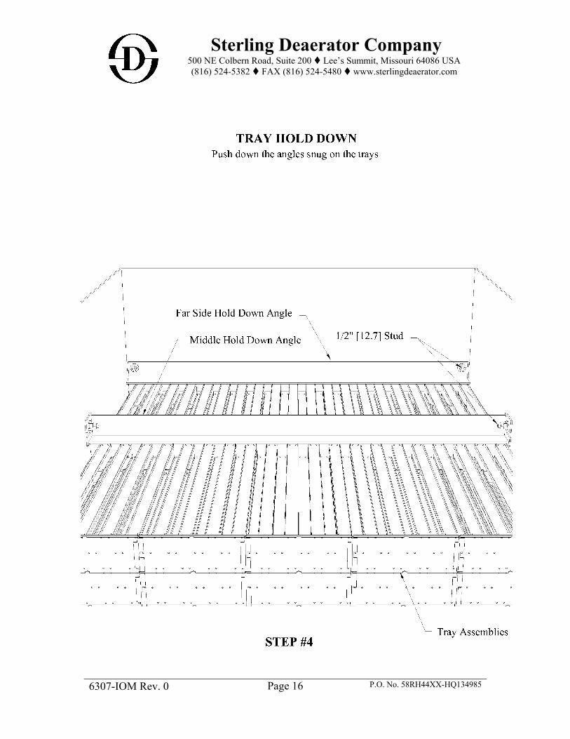
STEP 4. The hold-down angles are installed after all trays have been installed.
Slide the back hold-down angle over the bolts that stick through the back of the enclosure through the slots on the angle. Install the washers and lock nuts on the ½” [12.7mm] studs. Push down the angles snug on the trays and tighten the nuts.
NOTE: Only enclosures that are two bays deep will have a middle hold-down angle. If applicable, install the middle hold-down angle by sliding the angle over the bolts through the slots on the hold-down angle end plates. Install the washers and lock nuts on the ½” [12.7mm] studs. Push down the angles snug on the trays and tighten the nuts.
Slide the front hold-down angle bolts through the front of the enclosure through the slots on the enclosure wall. Install the washers and lock nuts on the ½” [12.7mm] studs. Push down the angles snug on the trays and tighten the nuts.
IMPORTANT: TRAYS SHOULD FIT SNUGLY SO PROCEDURE NEED NOT BE REPEATED.

Sterling Deaerator Company 500 NE Colbern Road, Suite 200 Lee’s Summit, Missouri 64086 USA (816) 524-5382 FAX (816) 524-5480 www.sterlingdeaerator.com
6307-IOM Rev. 0 P.O. No. 58RH44XX-HQ134985
Page 14
* 40 Trays for this Job

Sterling Deaerator Company 500 NE Colbern Road, Suite 200 Lee’s Summit, Missouri 64086 USA (816) 524-5382 FAX (816) 524-5480 www.sterlingdeaerator.com
6307-IOM Rev. 0 P.O. No. 58RH44XX-HQ134985
Page 15
Sterling Deaerator Company 500 NE Colbern Road, Suite 200 Lee’s Summit, Missouri 64086 USA (816) 524-5382 FAX (816) 524-5480 www.sterlingdeaerator.com
6307-IOM Rev. 0 P.O. No. 58RH44XX-HQ134985
Page 16
Sterling Deaerator Company 500 NE Colbern Road, Suite 200 Lee’s Summit, Missouri 64086 USA (816) 524-5382 FAX (816) 524-5480 www.sterlingdeaerator.com
6307-IOM Rev. 0 P.O. No. 58RH44XX-HQ134985
Page 17
2.4 Operation of the Deaerator Efficient removal of the non-condensable gasses from the deaerating heater requires that the vent valve be opened sufficiently to allow complete discharge of the gasses passed to the vent condenser outlet pipe. The maximum concentration of the non-condensable gasses such as oxygen or carbon dioxide passing out the vent depends on the degree of condensation produced by the steam and gas mixture passing through and around the spray created by the special spray valve. The optimum condition is when the unit is venting all non-condensable gasses with the minimum steam loss. This point can only be found through trial and error. A vent condenser is not functioning properly when there is entrainment of water in the plume discharging to the atmosphere or where a steam plume cannot be observed, or the plume appears to be puffing. These malfunctions can be caused by any of a number of reasons such as insufficient vent opening, erratic spray valve action or incorrect vent piping. 2.4.1 Venting The vent valve should not be operated in a closed position. Normally, the valve should be open one or more turns to allow for complete removal of the gasses. To assure that the vent valve is not inadvertently closed completely a small hole may be drilled in the gate of the vent valve. To determine the correct amount of opening required, the vent valve should be opened approximately one or two turns and the effect on the temperature noted. If no appreciable effect on the temperature is noted after a period of one hour, oxygen tests should then be made to determine the effectiveness of venting; satisfactory reduction of oxygen is obtained when tested by a recognized sampling and testing procedure. The vent setting of the valve can be further decreased by tightening the vent valve. Normally, the plume of steam would indicate sufficient venting if it appears firm and rises approximately 18 inches (457.2 mm) to 3 feet (914.4 mm) above the termination of the pipe. If after reducing the vent valve openings a drop in operating temperature is observed, or a difference between outlet temperature of the water in comparison with the saturated temperature of the steam is observed, then the venting is not adequate and the vent valve or orifice must be opened further. 2.4.2 Orifice Type Vent Where loads are very small or where uniform operation (flow rates and pressures) can be expected for long periods of time a fixed orifice may be employed. This would usually consist of a drilled pipe cap mounted above the vent valve. The vent valve should always be full open, and precautions noted above should be observed. The optimum size of the hole in the orifice cap can best be found by drilling a small hole (1/8" to 1/4") (3.2 to 6.4 mm) and checking the dissolved oxygen in the effluent. Also, observe the water temperature to see that it is at saturation temperature of the steam within the heater. If the oxygen reading is high or the temperature is low, increase the hole size in the orifice and recheck. Repeat until oxygen is below the guarantee level and the temperature rises to steam saturation temperature.

Sterling Deaerator Company 500 NE Colbern Road, Suite 200 Lee’s Summit, Missouri 64086 USA (816) 524-5382 FAX (816) 524-5480 www.sterlingdeaerator.com
6307-IOM Rev. 0 P.O. No. 58RH44XX-HQ134985
Page 18
2.5 Insulation The deaerating heater, storage tank and all equipment carrying hot water or containing steam should be thoroughly insulated to prevent loss of heat. This includes all external stiffening rings. Sample connections and thermometer wells should not be covered, and provision should be made to allow for annual inspection through manholes and to inspect control valves, level controllers, etc., without damaging the insulation and covering. The insulation selection, in addition to protecting the vessel and preventing heat loss, must take personnel health and safety into consideration. The outer surface of the insulation and lagging steam must be maintained at a temperature which is safe for personnel working on or near the equipment. Insulation materials must comply with OSHA regulations.
2.6 Elevation of Deaerating Heater Any deaerating heater must be elevated above the boiler feed pump to insure sufficient net positive suction head on the inlet side of the boiler feed pump. The minimum head required on the suction of the pump should be carefully checked with the pump manufacturer, emphasizing the fact that the pump is handling water at a temperature corresponding to the saturated temperature of the steam supplied to the deaerating heater. Flashing and consequent "steam binding" of the pump may occur if the boiler feed pump is operated with low or negative suction head. The suction head is considered that distance from the low water line in the deaerating heater or bottom of storage tank to the centerline of the feed pump.
2.7 Installation Vessel installation should follow all applicable plant and code safety regulations. The vessel installation chronology is as follows: (Note: Lugs should be confirmed adequate for lifting the entire vessel dry weight. On occasion slings are required to lift the entire empty weight since some lugs are added as quides only). 1. Install storage tank slide plates on the support structure per Sterling Installation Drawings.
(SEE: A1-6307-3 Rev. 1 Slide Plate Details drawing) 2. Set storage tank on support structure and add anchor bolting or set vessel on anchor bolts. 3. The heater vessel should then be mounted on top of the storage vessel. 4. The connecting nozzles between the vessels shall be welded. Slight adjustment may be
required to obtain the best fit-up of the connecting nozzles. 5. Add connection bolting between heater supports and corresponding supports on storage
vessel. 6. Secure and tighten anchor bolts and connection bolting. All sliding support bolting should
be hand tightened and tack welded only. 7. Connect process piping in appropriate sequence.

Sterling Deaerator Company 500 NE Colbern Road, Suite 200 Lee’s Summit, Missouri 64086 USA (816) 524-5382 FAX (816) 524-5480 www.sterlingdeaerator.com
6307-IOM Rev. 0 Page 19 P.O. No. 58RH44XX-HQ134985
DEAERATOR AND STORAGE TANK INSTALLATION FLOW CHART

Sterling Deaerator Company 500 NE Colbern Road, Suite 200 Lee’s Summit, Missouri 64086 USA (816) 524-5382 FAX (816) 524-5480 www.sterlingdeaerator.com
6307-IOM Rev. 0 Page 20 P.O. No. 58RH44XX-HQ134985
Inspection should occur before start up. Every deaerating heater has been designed to meet specific operating conditions. Fabricating and inspection procedures are the best known. The material selected for each of the components has been proven over many years of service to be the best for the service within economic considerations. However, before the unit is installed and operated, it is strongly suggested that the deaerating heater be rechecked to insure no damage has occurred to the heater since its inspection. The spray valves should be checked to insure that they are installed correctly with the spring on the water side of the water chamber. Stainless steel hex nuts and lock washers are used to fasten the valve to the vessel so they will not loosenunder any load. The nuts should be tight and the gasket should be firmly seated. Inspection should be made to make sure all internal inspection plates are in place, tightly bolted, and that all debris has been removed from the tank. This is especially true after all piping connections are made and the unit is flushed out. It is recommended that the water side of the water box be checked if the pipe lines have been hydraulically flushed, as often debris will wash in and will lodge in this compartment and eventually work through the deaerating heater to the boiler feed pump. Baffles should be inspected to insure that no damage occurred during shipping or installation, such as cracks of welds or other points that could be subject to damage. Trays are shipped either separately boxed or are sometimes installed within the heater. Refer to your job bill of material under "Tray Assembly" to determine how these are shipped. If shipped within the heater, inspection should be made to ascertain that no damage accrued during shipping or rigging. The trays should be level and nested together with no gaps or spaces between. To inspect or install trays, it is necessary to open the access door and the inner tray door or holding braces. The trays should be installed as indicated on the internal assembly drawing. Some trays have serrated edges; install these with the edges (saw teeth) pointing down. For trays with channel-shaped sections, install with the channel flanges pointed up. The vent piping should be installed with no sharp vent bends or trays that could obstruct the flow of gasses. The ideal vent pipe rises vertically from the heater to the valve located above the junction of the vessel in a short length of pipe above the valve. This is normally satisfactory where a slight amount of steam vapor can be tolerated in the area of the deaerating heater. Where this is not possible and it becomes necessary to pipe the vent line to the outside atmosphere, precautions must be taken to avoid consistently long lines with a great number of turns. Horizontal runs should be avoided wherever possible. Trapped pockets in pipe lines must be eliminated if the heater is to operate successfully. The vent plume should be visible to the operator to enable him to periodically check the plume; therefore, avoid piping the vent to stacks, risers, or other closed systems unless provision is made to allow for this periodic inspection.

Sterling Deaerator Company 500 NE Colbern Road, Suite 200 Lee’s Summit, Missouri 64086 USA (816) 524-5382 FAX (816) 524-5480 www.sterlingdeaerator.com
6307-IOM Rev. 0 P.O. No. 58RH44XX-HQ134985
Page 21
2.8 Operation of Equipment After the unit has been completely installed and all equipment has been tested and checked, the following procedures should be followed when commencing operation of a deaerating heater: CAUTION!: BEFORE OPERATION OF THIS EQUIPMENT, THE USER MUST READ THIS MANUAL, ESPECIALLY THE SECTION CONCERNING SAFETY. a. The start-up period should be carefully planned so that wastage of water and steam to the
drain do not unduly overload existing facilities such as pumps, engines, heaters, etc. b. Flush out all lines and tanks with water until there is no apparent indication of foreign
matter or rust. Spray valves and nozzles should be free of foreign material. c. Manually check all controls to see that each is working freely and that all shipping stops
are removed. Refer to the descriptive literature and operating instructions for proper operation and adjustment of controls, instruments and special equipment.
d. Check to see that all instruments are operating and indicating correctly. e. Open all vent valves or open orifice bypasses to atmosphere. If orifice plates are not
bypassed, remove the orifice plate to allow free venting to atmosphere. f. Close the outlet valve from the heater to the feed pump. g. Start the flow of inlet water and slowly increase to 15% to 30% of the design inlet flow
rate. IMPORTANT NOTE: Large industrial and central station deaerators and most scrubber type
deaerators which operate from 50 PSIG to 150 PSIG (3.4 BarG to 10.3 BarG) frequently have a design temperature rise (inlet water temperature to outlet water temperature) of up to 150°F (66ºC) Starting up with cold water at high inlet water rates can require steam flows exceeding design limits. This can cause violent pressure fluctuations and possible damage to the internals. The following formula shows the relationship to consider.
1@
@
StartUpVolumeSpecificSteamRiseeTemperaturStartUpRateWaterStartUp
DesignVolumeSpecificSteamRiseeTemperaturDesignRateWaterDesign
h. After making certain that adequate steam pressure is available, open steam valve slowly
admitting steam into the deaerator. Expect some rumbling with a cold vessel. Check deaerator pressure gauge and be certain to maintain a positive pressure on the vessel. A proper start-up is not possible with inadequate steam pressure.
i. CAUTION!: Do not fill the deaerator with steam and then start the water. This will create noise and vibration which can damage the internals of the deaerators. Deaerators not designed for full vacuum can be partially collapsed. Caution is urged even if a vacuum relief valve is installed.
A similar condition can occur where the deaerator sits at idle for a time with steam pressure on the vessel but no water entering a condensate inlet. Since the spray valves

Sterling Deaerator Company 500 NE Colbern Road, Suite 200 Lee’s Summit, Missouri 64086 USA (816) 524-5382 FAX (816) 524-5480 www.sterlingdeaerator.com
6307-IOM Rev. 0 P.O. No. 58RH44XX-HQ134985
Page 22
are not water tight, the water box will drain and then fill with steam. Where this situation is likely to occur, provisions for flushing the steam from the condensate line and water box with water from the deaerator storage tank or other source (at saturation temperature) prior to condensate return must be provided. If hot water is not available, the unit must be shut down and started as in steps E, F, and G, etc. above.
j. As water moves up to and reaches the operating level, check the operation of the limit switches and inlet controller. Manually, continue water flow and check high level overflow controls.
k. When a strong flow of steam issues from the vents, start throttling back on the vent valves and check storage tank temperatures. The gauge should read 2°F to 3°F (1ºC to 2ºC) below saturation temperature at the existing pressure.
l. Open steam valve full open so that steam pressure control is operating. m. Throttle back vent valves to operating positions. Install orifice plates if removed. Final
vent valve position or orifice plate sizing must be determined in conjunction with oxygen tests during unit operation.
n. Deaerator is now ready for operation. Open outlet to feed pumps. 2.8.1 Recommended Good Practice for Temperature Changes A deaerator is a direct contact heat exchanger. This type of equipment can be exposed to severe thermal and pressure excursions which can cause damage to the vessel due to stress corrosion, corrosion fatigue and similar phenomena. Cyclic operation is a major contributor to the damage. These practices apply to cyclic and non-cyclic equipment. To assure long life, the guidelines below should be followed: a. Changing cold or hot water admission to the waterbox must be accomplished in a
controlled manner. The control must assure that rate of temperature change of the metal in the shell or the water box does not exceed 400°F (222ºC) per hour with instantaneous changes not greater than 50°F (28ºC) per minute for total excursion of 150°F (83ºC).
b. Pressure changes in the heater must be gradual. Pressure changes are accompanied by changes in temperature. The change in temperature should not exceed the limitations above.
c. Cold start-up can severely stress a deaerator. It is not unusual to have start-up steam with temperatures of 600°F (315ºC) and higher. To avoid severe thermal shock, it is recommended that cold start-ups be preceded by a warm-up period. The warm-up consists of slowly admitting start-up steam with the vents open and no flow into the water box. The steam flow should be regulated to permit the steel shells to heat at a rate of 50°F (28ºC) per minute up to about 200°F (93ºC). Water in the storage tank should also be heated to the same value. Note that the heating of the storage tank and its water will be much slower than the heater portion of the deaerator.
When the entire vessel and its contents are heated, the steam supply should be shut off and any remaining steam vapor should be vented. Then proceed with the normal start-up.

Sterling Deaerator Company 500 NE Colbern Road, Suite 200 Lee’s Summit, Missouri 64086 USA (816) 524-5382 FAX (816) 524-5480 www.sterlingdeaerator.com
6307-IOM Rev. 0 P.O. No. 58RH44XX-HQ134985
Page 23
d. Accelerated cooling is often desirable for repair or maintenance. However, accelerated cooling using cold water can cause thermal shock and equipment damage. Accelerated cooling can be accomplished using a cooling fluid which is 100°F to 150°F (56ºC to 83ºC) lower than the metal temperature until the metal has cooled to about 250°F (121ºC). The rate of change of metal temperature should stay in the 100°F/hr.(56ºC/hr.) range. Once the metal is at or below 250°F (121ºC), cooling water of 60°F to 70°F (16º to 21ºC) may be used.
2.8.2 Hydrostatic Testing Hydrostatic test pressure may create stresses higher than the equipment design stress. This is not harmful unless hydrostatic tests are performed using very cold water. In general, the hydrostatic tests should be done using the guidelines of the ASME Code, Section VIII, Div. 1, Paragraph UG-99.
2.9 Recommended Procedure for Storage of Pressure Vessels 2.9.1 Internal Preparation Vapor Absorption - The shell and all carbon steel internal parts are to be blast or power wire brush cleaned and given a protective coating such as Leeder 228. All openings are to be sealed and taped and a vapor absorbing chemical installed in the shell. The normally used absorption chemicals are Silica Gel or activated alumina and are used in quantities of one (l) pound (0.45 Kg) for every 100 cu. ft.(2.8 Cu.M) of vessel. This method is suited for storage periods of six to twelve months depending upon the environment. Longer periods would require that the chemicals be replaced periodically as the manufacturer recommends. Nitrogen Blanketing - No internal preparation of the vessel shell is required. This method requires that all openings are tightly sealed, gasketed, and/or welded shut. Nitrogen (or other inert gas) is injected into the shell. The vessel is pressurized to 3 to 5 PSI (0.2 to 0.3 BarG) and all air vented. Vessels may be stored in any environment for indefinite periods but constant checking of the pressure must be made and the nitrogen cylinders replaced as required.

Sterling Deaerator Company 500 NE Colbern Road, Suite 200 Lee’s Summit, Missouri 64086 USA (816) 524-5382 FAX (816) 524-5480 www.sterlingdeaerator.com
6307-IOM Rev. 0 P.O. No. 58RH44XX-HQ134985
Page 24
2.9.2 External Preparation Application and dry film thickness are to be in accordance with the manufacturer's recommendations for the paint selected. In selecting the type of external preparation, consideration must be given to the environmental conditions and maintenance provisions available. Exposure environments arranged in order of increasing severity are as follows: A. Dry interior climate or arid regions. B. Rural or light industrial areas. C. Frequently wet climates.
D. Continuously wet climates. E. Corrosive areas.
Paint systems for exposure A usually consists of a single coat of Red Oxide Primer. For the remaining exposures, paint systems would normally consist of one or two coats of rust inhibiting primer and one or two finish coats depending on the severity of the conditions. Before selecting painting systems and materials for exposures C through E, consideration must be given to the specific climate conditions at the storage site. Where day/night temperature changes exceed 30°F (16.7ºC), special attention should be given to the preparation of the metal surface and selection of the primer paint. Under these conditions, the metal surfaces should be blast cleaned to remove all mill scale which might otherwise flake off due to expansion and contracting of the vessel. The type of primer and finish system selected should be compatible with the particular expansion characteristics of the vessel and the final operating temperatures. Suggested Paint Systems are as follows:
Primer Coat Finish Coat Exposure First Coat Second Coat First Coat Second Coat
A Dry Interior
climate or arid regions
Red Oxide Not Required Not Required Not Required
B Rural or light
industrial areas Inorganic Zinc Not Required Not Required Not Required
C Frequently wet
climates Inorganic Zinc Inorganic Zinc Not Required Not Required
D Continuously wet
climates Inorganic Zinc Inorganic Zinc
Customer Preference
Not Required
E Corrosive areas Inorganic Zinc Inorganic Zinc
Customer Preference
Customer Preference

Sterling Deaerator Company 500 NE Colbern Road, Suite 200 Lee’s Summit, Missouri 64086 USA (816) 524-5382 FAX (816) 524-5480 www.sterlingdeaerator.com
6307-IOM Rev. 0 P.O. No. 58RH44XX-HQ134985
Page 25
2.9.3 Maintenance Requirements Short-term Storage (Up to 12 Months) The absorption material should be checked after three (3) months and then monthly thereafter. Expanded material is replaced as required. The exterior portions of the shell are to be visually inspected periodically. Long-term Storage (Over 12 Months) The inert gas cylinders and vessel must be checked weekly for any loss of pressure and replaced as required. The exterior portions of the shell are to be visually inspected periodically and the finish repaired as required using the finish paint specified. 2.9.4 Suggested Prime and Finish Coats Primer Coat Red Iron Oxide - Sherwin-Williams Company Inorganic Zinc - Carboline Corporation Finish Coat Polyamide Epoxy - Porter Company Zinc-Lock No. 500 Series

Sterling Deaerator Company 500 NE Colbern Road, Suite 200 Lee’s Summit, Missouri 64086 USA (816) 524-5382 FAX (816) 524-5480 www.sterlingdeaerator.com
6307-IOM Rev. 0 P.O. No. 58RH44XX-HQ134985
Page 26
3. Design Specification ~ Drawings INVITATION TO TENDER (ITT) NO 700413 FOR DEAERATOR 1168V0104 SDC JOB: 2017-6307 KWINANA, WA, AUSTRALIA P.O. NO.: 58RH44XX-HQ134985 WESFARMERS CHEMICALS, ENERGY & FERTILISERS KWINANA, WA, AUSTRALIA
MODEL NO: 72 VTHS-5137-10Ø149 ASME SECTION VIII, DIV I
HEATER VESSEL: 6’-0” OD Heads 5’-0” Shell Tan-Tan Length 9.5 mm Shell Thickness 9.5 mm Head Thickness SA-516-70 Head/Shell Material
STORAGE VESSEL: 10’-0” OD Heads 14’-9” Shell Tan-Tan Length 12.7 mm Shell Thickness 12.7 mm Head Thickness SA-516-70 Head/Shell Material
Design Pressure (Internal): 94.28 psig (5.10 kg/cm²g) Full Vacuum Design Temperature (Heater/Storage): 392° F (392° F Steam) (200.0°C (200.0°C Steam) Operating Pressure: 1.39 kg/cm²abs (19.78 psia) Operating Temperature: 227° F (109º C) Outlet Capacity: 183,879 lbs/hr (83,407 kg/hr) Storage Capacity: Storage capacity is based on specified dimensions (3048 mm OD x 4490 mm T-T). Oxygen Guarantee: 0.005 ml/l (7 ppb) Spray Valves: 316-L S.S. / Quantity: 6 Trays: 37” Length / 430 S.S. / Quantity: 40 Reference Drawings: 1168-4-0104/001 A1-6307-1 Rev. 1 General Notes & Nozzle Schedule 1168-4-0104/000 A1-6307-2 Rev. 3 Outline Drawing 1168-4-0104/002 A1-6307-3 Rev. 1 Slide Plate Details

NOZZLE SCHEDULE
MARK QUAN DNSIZE
ENDPREP./RATING STYLE MATERIAL
CUSTPIPESCH.
DESCRIPTION REMARKS
N1
N2
N6
N10
N13
K1
M2
DCH
EQH
N3
N4
N5, N15
N7
N8
N9
N11, N12
N14
K2A/B, K3A/B
K4
K5
M1
DCS
EQS
1
1
1
1
1
1
1
1
1
1
1
2
1
1
1
2
1
4
1
1
1
1
1
80
100
200
50
80
50
600
300
250
150
50
50
150
100
50
50
50
50
50
50
600
300
250
150#
150#
150#
150#
150#
150#
150#
150#
150#
150#
150#
150#
150#
150#
150#
150#
150#
150#
150#
150#
150#
150#
150#
RFWN
RFWN
RFWN
RFWN
RFWN
RFWN
RFWN
RFWN
RFWN
RFWN
RFWN
RFWN
RFWN
RFWN
RFWN
RFWN
RFWN
RFWN
RFWN
RFWN
RFWN
RFWN
RFWN
316-L SS
C.S.
C.S.
316-L SS
C.S.
C.S.
C.S.
C.S.
C.S.
C.S.
C.S.
C.S.
C.S.
C.S.
C.S.
316-L SS
C.S.
C.S.
C.S.
C.S.
C.S.
C.S.
C.S.
---
---
---
---
---
---
---
---
---
---
---
---
---
---
---
---
---
---
---
---
---
---
---
MAKEUP INLET (THROUGH SPRAY VALVES)
PUMPED CONDENSATE (THROUGH SPRAY PIPE ABOVE TRAYS)
STEAM INLET
VENT
SAFETY VALVE
PRESSURE
MANWAY
DOWNCOMER
EQUALIZER
FLASHING CONDENSATE INLET
MANUAL FILL
PUMP RECIRC
PUMP SUCTION
OVERFLOW
DRAIN
CHEMICAL INLET
VACUUM BREAKER
BRIDLE CONNECTIONS
PRESSURE
TEMPERATURE
MANWAY
DOWNCOMER
EQUALIZER
NOMINALSIZE
3"
4"
8"
2"
3"
2"
24"
12"
10"
6"
2"
2"
6"
4"
2"
2"
2"
2"
2"
2"
24"
12"
10"
W/ SPRAY PIPE - SEE NOTE 20
W/ BAFFLE
W/ VORTEX BREAKER
W/ DRIP SHIELD
W/ BAFFLE
W/ VORTEX BREAKER
W/ SCREEN
FLUSH INSIDE
W/ STAND PIPE
W/ TEE BAFFLE
W/ 150 mm INTERNAL PROJECTION
W/ DAVIT
W/ DAVIT
GENERAL NOTES 1) CONSTRUCTION PER ASME SECT VIII, DIV. 1, 2015 EDITION / HEI COMPLIANT / AS1210 WITH STAMP.
2) DESIGN:PRESSURE (INT): 5.10 kg/cm²GPRESSURE (EXT): FULL VACUUMTEMPERATURE: 200.0 °C (200.0 °C STEAM)
OPERATING:PRESSURE: 1.39 kg/cm²ABS
TEMPERATURE: 109 °CHYDROTEST PRESSURE: 6.63 kg/cm²G]
3) NDE REQUIREMENTS:RADIOGRAPHY:
LONGITUDINAL SEAMS: RT1 (100% JOINT EFFICIENCY)CIRCUMFERENTIAL SEAMS: RT1 (100% JOINT EFFICIENCY)
MT OR PT ON INTERNAL NOZZLE WELDS BEFORE PWHT
4) CORROSION ALLOWANCE INCLUDED: 3 mm
5) HEAD MATERIAL: SA-516-70 SHELL MATERIAL: SA-516-70
6) STRESS RELIEF: 1 STAGE PWHT @ 593 °C - 649 °C
7) HEADS: 2:1 ELLIPTICAL
8) ALL MATERIAL FOR NOZZLES SHALL CONFORM TO CUSTOMER SPECIFICATION AND A SUITABLE ASME SPECIFICATION.
9) ANY PIPE FABRICATED FROM ROLLED PLATE SHALL CONFORM DIMENSIONALLY TO CUSTOMER SPECIFICATION AND TOWELDED PIPE SPECIFICATION ASME SA-53.
10) SURFACE PREPARATION:(INTERNAL) SSPC-SP6 COMMERCIAL BLAST ONE COAT WATER-SOLUBLE RUST INHIBITOR APPLIED.(EXTERNAL) VESSEL SURFACE: SSPC-SP10 NEAR WHITE BLAST WITH PAINT PER SYSTEM G. COLOR: GRAY.
SADDLES: SSPC-SP10 NEAR WHITE BLAST WITH PAINT PER SYSTEM D. COLOR: LIGHT BLUE GRAY.
11) UNLESS NOTED OTHERWISE, ALL FLANGE BOLTING SHALL STRADDLE LONGITUDINAL VESSEL CENTERLINES.
12) UNLESS NOTED OTHERWISE, INTERNAL NOZZLE PROJECTION SHALL NOT EXCEED LENGTH REQUIRED FOR NOZZLEREINFORCEMENT.
13) UNLESS NOTED OTHERWISE, ALL PIPING FOR ACCESSORIES SHALL BE SUPPLIED BY OTHERS.
14) UNLESS NOTED OTHERWISE, ALL FOUNDATION AND CONNECTION BOLTING SHALL BE SUPPLIED BY OTHERS. BOLTINGAND GASKETS BETWEEN TANKS SHALL BE SUPPLIED BY FABRICATOR.
15) UNLESS NOTED OTHERWISE, ALL PIPE FOR NOZZLES SHALL BE ASME SA-106-B.
16) ALL CONNECTIONS SHALL BE SUITABLY PREPARED FOR SHIPMENT TO PREVENT CORROSION OR DAMAGE. HYDROTESTBLANKS SHALL BE REMOVED PRIOR TO SHIPMENT.
17) ASBESTOS OR ASBESTOS BEARING MATERIAL IS NOT ALLOWED.
18) NOZZLES SHALL HAVE FULL PENETRATION ATTACHMENT WELDS.
19) INSULATION SUPPORTS PER ES-14-102-14 FOR 70 mm THICK INSULATION. INSULATION BY OTHERS.
20) NOZZLE HAS INTERNAL SPRAY PIPE WITH 22 Ø25 mm HOLES.
6307
NOTE 1) FABRICATOR SHALL STAMP (2) NAMEPLATES AS SHOWN ABOVE.
2) THIS IS NOT THE ASME NAMEPLATE. THE ASME NAMEPLATE SHALL BE SUPPLIEDBY THE VESSEL FABRICATOR.
EQUIPMENT NO.: 1168V0104
500 N.E. Colbern Road, Suite 200, Lee's Summit, MO 64086Phone: (816) 524-5382 Fax: (816) 524-5480
www.sterlingdeaerator.comRGA8-31-170 DET
MICHAEL HANLIN9-6-17
FIRST ISSUE1 1168-4-0104/000 OUTLINE OF DEAERATORRGA9-6-171 DETDRAWING RENUMBERED & FOR APPROVAL

M1
N6
N8K3BK5N7N9K2B
EQSDCS
N2N1N10 N13
N14N15K4
N5K3A
DCHEQH
K2AN3N4
N12 N11
M2K1
1065
600550
10501050
1500 1500
500
200
600
1190
1500
1950
1250
1450
1650
1950
940 REQUIRED TOREMOVE TRAYS
1020
GRAB BAR
INTERNAL LADDERRUNGS
FIXEDSADDLE
SLIDINGSADDLE
249
LLW
L
500
LWL
2090
NW
L
2342
HW
L
2591
HH
WL
300
1140 TYPICAL
FARSIDE
FARSIDE
FARSIDE
1750
TYP
ICAL
1750
TYP
ICAL
(2) LIFTING LUGS
NAMEPLATE BRACKET.INCLUDES STERLING NAMEPLATE.
600
"A" "A"
M1
N1
N11N12
N13N4 N3K3A
N5K4
N15
N14
M2
K1
300 300
2245
4490 STRAIGHT (TANGENT - TANGENT)6405 OVERALL APPROXIMATE
13
13
N10
N2
INSULATION SUPPORTS PERA1-6307-1 NOTE "19"
45°
3048
OU
TSID
E DI
AMET
ER
3354
OVE
RALL
APP
ROXI
MAT
E
N6
K1
N6
N11 N12
M1
N8
N2N10 N13
N1
K3BN7
N9K2B
K5
M2
N14
DCHEQH
N15K4
N5K3A
DCSEQS
K2AN3
N4
150
25
1770
1720
710
1524
STR
AIG
HT
(TAN
GEN
T - T
ANG
ENT)
680
3490
2914
6404
OVE
RALL
APP
ROXI
MAT
E
1750
700
1829 OUTSIDE DIAMETER
10
10
450200
(2) LIFTING LUGS
1750
45°
NAMEPLATE BRACKET.INCLUDES STERLING NAMEPLATE.
FARSIDE
FARSIDE
EARTHING LUGEACH SADDLE
500 N.E. Colbern Road, Suite 200, Lee's Summit, MO 64086Phone: (816) 524-5382 Fax: (816) 524-5480
www.sterlingdeaerator.comRGA0 DET
MICHAEL HANLIN9-6-17
8-31-17 FIRST ISSUE
PLAN VIEW SCALE: AS SHOWN
PLAN VIEW SCALE: AS SHOWN
END VIEW SCALE: AS SHOWN
WEIGHTS (Approximate) EMPTY (HEATER)EMPTY (STORAGE)OPERATINGFLOODED
NOT INCLUDING FORCES AND MOMENTS FROMCUSTOMERS PIPING SYSTEM, SEISMIC OR WIND
LOADS, OR WEIGHT OF INSULATION
2397 kg 9819 kg45301 kg57096 kg
1) VACUUM RING QUANTITY, SIZE AND LOCATION SHALL BE DETERMINEDBY FABRICATOR.
1 1168-4-0104/001 GENERAL NOTES & NOZZLE SCHEDULE
WITH Ø28FIXED SUPPORT
SLOTSWITH 28 x 67
SLIDING SUPPORT
XX
LC
SECTION "A-A" BOLT SIZE = M24
HOLES
LC
89 89 89 89
1273000
2489
1244
.512
44.5
2286
1143
1143
1500 1500
127
NOTES:
HHWL : HIGH HIGH WATER LEVELHWL : HIGH WATER LEVELNWL : NORMAL WATER LEVELLWL : LOW WATER LEVELLLWL : LOW LOW WATER LEVEL
LEGEND:
2 1168-4-0104/002 SLIDE PLATE DIMENSION & INSTALLATION RGA1 DET9-6-17 DRAWING RENUMBERED & FOR APPROVAL
STERLING DWG. NO.A1-6307-02-R1
RGA2 DET9-29-17 MOVED NOZZLES "K5" & "N9". FOR APPROVAL
3 1-3-18 UPDATED STORAGE LOWER SADDLE DESIGN RGADET

1500 1500
3000
1143
1143
2286
178
6464
127
1245
7070
140
191
89 89 89 89
3(TYP.)
(4) Ø28HOLES FOR M24
BOLTS (TYP.)
(4) Ø28HOLES FOR M24
BOLTS (TYP.)
89 8989 89
76
152
1143
1143
2286
1500 1500
3000
76
1245
16583
83
229
241
3(TYP.)
(4) Ø28HOLES FOR M24
BOLTS (TYP.)(4) 28 x 67LONG SLOT
TYPICAL CROSS SECTION (FIXED SUPPORT) SCALE 1:4
TIGHTEN BASE NUT,THEN TIGHTEN TOPNUT TO BASE NUT.
(TYP.)
305
FIXED SADDLE
STRUCTURAL STEELSUPPORT (BY OTHERS)
3 (TYP.)
3(TYP.)
TYPICAL CROSS SECTION (SLIDING SUPPORT) (COLD POSITION)
NTS
191
241
STRUCTURAL STEELSUPPORT (BY OTHERS)
SLIDING SADDLEBASE NUT TO BE HANDTIGHTENED ONLY.
TACK WELD TO THEBOLT. (TYP.)
3.4
2.4
11.6
1770
TO
OF
SADD
LE
1758
.4 B
OTT
OM
OF
SLID
ING
SAD
DLE
500 N.E. Colbern Road, Suite 200, Lee's Summit, MO 64086Phone: (816) 524-5382 Fax: (816) 524-5480
www.sterlingdeaerator.comRGA0 DET
MICHAEL HANLIN9-6-17
8-31-17 FIRST ISSUE
SECTION "A-A" SUPPORT STEEL
SECTION "B-B" BOTTOM OF SUPPORTS
(COLD POSITION)
1 1168-4-0104/000 OUTLINE OF DEAERATORRGA1 DET9-6-17 DRAWING RENUMBERED, SCALE ADDED & FOR APPROVAL

Sterling Deaerator Company 500 NE Colbern Road, Suite 200 Lee’s Summit, Missouri 64086 USA (816) 524-5382 FAX (816) 524-5480 www.sterlingdeaerator.com
6307-IOM Rev. 0 P.O. No. 58RH44XX-HQ134985
Page 30
4. Deaerator Apparatus
4.1 Accessories The Bill of Material lists all accessories purchased with the deaerator. This could include any of the following: control valves and level controllers, gauge glasses, water thermometers, steam thermometers, steam pressure gauges, oil separators, oxygen test equipment, level or pressure recorders, relief valves, piping, etc. Sterling Deaerator furnishes only that equipment listed on the engineering Bill of Material. For operating any of the accessories or auxiliary equipment supplied with the deaerator, refer to separate instructions in this section, and to the accessory equipment which is contained elsewhere in this manual. ACCESS CAUTION: BEFORE ANY ENTRY OR ACCESS TO THIS VESSEL, REFER TO THE SAFETY SECTION OF THIS MANUAL. Provisions should be made for platforms or ladders so that various valves, controls, and instruments are accessible to the operator. Manholes should be accessible for internal inspection of the equipment.
4.2 Piping Connections Prior to connecting the deaerating heater to the piping, the heater and storage tank should be bolted firmly to the foundation and the interior should be inspected to ascertain that all interior parts are in position and working order. When connecting steam and water lines to the heater, care should be exercised in the piping arrangement. Include expansion joints, if necessary, to avoid imposing excessive piping loads upon the shell. Isolating gate valves in these lines are desirable, as they allow for complete isolation for cleaning or repairing, and are bypassed around inlet control valves or steam pressure reducing valves. Piping should be supported independently to avoid loads from being exerted upon the heater or storage shell or any nozzles. The pump suction line should be as large as practical and the use of sharp angle bends should be avoided. The line should be as direct to the boiler feed pump suction as possible. Vent piping should be installed with care to avoid any traps or pockets. A vertical line, short as possible, is best. A gate valve should be installed in this line. An alternative to this would be a gate valve with a pipe cap mounted above the valve. This pipe cap should be drilled with an orifice that

Sterling Deaerator Company 500 NE Colbern Road, Suite 200 Lee’s Summit, Missouri 64086 USA (816) 524-5382 FAX (816) 524-5480 www.sterlingdeaerator.com
6307-IOM Rev. 0 P.O. No. 58RH44XX-HQ134985
Page 31
will allow sufficient venting. This method is most feasible for a system that would have a fairly uniform amount of noncondensable gasses venting from it. Care must also be taken to avoid closing the gate valve at any time except for maintenance or change of the orifice. The drain line should be piped to waste and all of the connections made in accordance with the outline drawings using usual piping practice. Sampling lines should be installed using extreme care to avoid leakage of air into the line. For a full description of the installation of sampling lines, refer to the section under Oxygen Testing.
4.3 Relief Valves Relief valves, when furnished, are not designed to prevent excess pressure in the steam line. They are designed to relieve excess pressure which might occur in the deaerating heater when steam is flashed from high temperature waters returned to the heater in the form of trapped discharges, condensate returns, etc. These relief valves are sentinel type valves. Main steam line should be protected external to the deaerating heater to avoid over pressuring from any cause. They must be sized to completely remove any steam formed from pressure reducing stations, or other control devices, which may be installed between the deaerating heater and point of supply. They must also be capable of relieving the complete volume of steam flowing to the deaerating heater. Normally, the relief valves supplied have a release, and it is recommended that occasionally this release be manipulated to check free movement and to avoid freezing of the valve seat. This can also be opened when starting the deaerating heater to relieve displaced air when filling the unit. WARNING: THE DISCHARGE FROM THESE VALVES CAN CAUSE SEVERE INJURY. PERSONNEL PROTECTION SHOULD BE INSTALLED BY THE OWNER OR OPERATOR. REFER TO THE SAFETY SECTION OF THIS MANUAL.
4.4 Vacuum Breakers Vacuum breakers are occasionally supplied to protect shells from external pressure where the vessel has not been designed to withstand this force. When a vacuum breaker opens, there is a definite malfunction within the deaerating heater, as normally this vacuum breaker should never open. It will only open when there is an insufficient supply of steam. Water going to service during these times could conceivably contain dissolved oxygen. Vacuum breakers which are supplied are steam tight, suitable for the design pressure of the vessel, and are set to open at the slightest vacuum. These should be checked periodically to insure that the seats have not frozen or allowed to become excessively dirty.

Sterling Deaerator Company 500 NE Colbern Road, Suite 200 Lee’s Summit, Missouri 64086 USA (816) 524-5382 FAX (816) 524-5480 www.sterlingdeaerator.com
6307-IOM Rev. 0 P.O. No. 58RH44XX-HQ134985
Page 32
4.5 Thermometers Thermometers are supplied only when ordered and then they are usually of the indicating type. They are installed to indicate the temperature within the storage tank. The thermometer wells are usually of the separable socket type with extension neck and with union connections. It is possible to remove the thermometer for calibration without reducing the pressure in the deaerating heater. For special installations, indicating, remote, or recording, instruments can be supplied. Temperatures external to the heater often supply useful information. This would be the temperature of any water stream coming to the heater, temperature of steam to the heater, and the temperature of the water at the boiler feed pump.
4.6 Pressure Gauges Pressure gauges are only supplied when ordered and are usually of the bourdon tube type which are used to indicate the steam pressure. A siphon should be installed between the vessel and the gauge to insure accurate reading of the gauge. The gauge is usually installed to indicate steam pressure in the shell of the deaerating heater. On special installations or where specifically required for remote control, indicating or recording pressure gauges can be supplied. It is often useful to have pressure at sources external to the heater should information ever be required, such as pressure upstream of the inlet control valves, steam header piping and feed pump suction.
4.7 Other Equipment For a description of the other equipment sometimes furnished with deaerators, such as inlet valves and controllers, overflow valves and controllers, tray banks, spray valves, etc., refer to the appropriate sections of this manual which outline installation and operating procedures to be used.

Sterling Deaerator Company 500 NE Colbern Road, Suite 200 Lee’s Summit, Missouri 64086 USA (816) 524-5382 FAX (816) 524-5480 www.sterlingdeaerator.com
6307-IOM Rev. 0 P.O. No. 58RH44XX-HQ134985
Page 33
4.8 Maintenance and Inspection Normally, deaerating equipment requires relatively minimal maintenance. The operation should be completely automatic. For normal operation, little or no maintenance is required, except for the usual attention required for instrumentation and controls. Complete annual inspection should be made of this equipment. In plants where duty is unusually severe, or abnormal water supplies are used, inspection should be required semi-annually or more frequently. CAUTION: BEFORE ANY ENTRY OR ACCESS TO THIS VESSEL FOR INSPECTION PURPOSES, REFER TO THE SAFETY SECTION OF THIS MANUAL. These inspections should include the following: a. Internal inspection for evidence of corrosion, scaling, cracking, or broken or worn parts. b. Spray Valve: Valve must seat firmly. Check the plug for debris. Valve nuts should be
tight with no evidence of leakage under gasket. If a disc appears to hang down, the spray valve can easily be adjusted by removing it from the tank, loosening the top hex nut and hand tighten the spring retainer until the valve disc just seats, then turn one-quarter turn more. Tighten top hex nut firmly and reinstall.
c. Spray Nozzle: Should likewise be checked for foreign matter and see that all holes are clean and clear.
d. Check manhole gasket, replace if there is evidence of leaks or deterioration of the gasket. e. Check operation of all controllers; they should move freely and not have excessive play.
Make any necessary adjustments, paying particular attention to the overflow valve and controller as this is not used frequently and may have a tendency to corrode and freeze into position.
f. Open and close all gate valves that have not been used since last inspection. Lubricate when necessary.
g. Recalibrate thermometers, pressure gauges and any other instruments. h. Inspect insulation. i. After unit is returned to service, oxygen testing should be performed with more
frequency to ascertain that the vent setting is correct.

Sterling Deaerator Company 500 NE Colbern Road, Suite 200 Lee’s Summit, Missouri 64086 USA (816) 524-5382 FAX (816) 524-5480 www.sterlingdeaerator.com
6307-IOM Rev. 0 Page 34 P.O. No. 58RH44XX-HQ134985
4.9 Bill of Material
WESFARMERS CHEMICALS, ENERGY & FERTILISERS INVITAION TO TENDER (ITT) NO. 700413 FOR
DEAERATOR 1168V0104 DEAERATOR FOR THE SODIUM CYANIDE PLANT (SCP1)
PURCHASE ORDER NO.: 370266 OH
STERLING JOB NO.: 2017-6307
BILL OF MATERIAL DOCUMENT NO.: 6307-BOM
STERLING REVISION: 0
REVISION DATE DESCRIPTION BY CHECKED APPROVED
0 1-Sep-17 Initial Transmittal MRH SRW SDR

Sterling Deaerator Company500 NE Colbern Road, Suite 200 • Lee’s Summit, MO 64086 (816) 524-5382 • FAX (816) 524-5480 • www.sterlingdeaerator.com
BILL OF MATERIAL6307-BOM
PAGE 1 of 1
SDC PO
ITEM QTY TAG NO'S DESCRIPTION SIZE DWG PART NO MAT’L SUPPLIED BY NOTES
-01
1 1 SPRAY-TRAY DEAERATING HEATER
Heater
Storage
OPERATING PRESSURE: 1.36 barabsOPERATING TEMPERATURE: 109 ºCOXYGEN GUARANTEE: 0.005 ML/L (7 PPB)CONSTRUCTION CODE: Section VIII, Div. 1, 2015 edition, HEI Compliant, AS1210DESIGN PRESSURE, INTERNAL / EXTERNAL:5.00 barG/ FULL VACUUMDESIGN TEMPERATURE: 200°C (200°C Steam)
83,407 kg/hr
1,829 mm OD X 1,524 mm Str(TAN-TAN)
3,048 mm OD X 4,490 mm Str (TAN-
TAN)
A1-6307-1A1-6307-2
72 VTHS-5137 -10ø149
SA-516-70
SA-516-70
STERLING/VESSELTECH
ALL NUTS/BOLTS AND GASKETS FOR ANY ACCESSORY ITEM (EXCEPT AS LISTED) ARE SUPPLIED BY OTHERS ITEMS LISTED BELOW SHALL BE SHIPPED LOOSE WITH ALL PIPING, EXCEPT AS NOTED, BY OTHERS
SEE DETAIL DRAWINGS FOR PIPING INFORMATION
2 6 SDC SPRAY VALVES PN400 316L SS STERLING INSTALLED PRIOR TO SHIPMENT3 6 Spray Valve Canister PN445-316LSS 316L SS STERLING/
VESSELTECHINSTALLED PRIOR TO SHIPMENT
-034 40 SDC 37" LENGTH TRAY ASSEMBLIES 340mm L x 280mm
W x 102mm HPN402-37-SL-430
SS430 SS STERLING INSTALLED PRIOR TO SHIPMENT
5 2 NAMEPLATE SDC 102mm X 178mm 304 SS STERLING STERLING DEAERATOR COMPANY6 2 TAG WARNING MANWAY ENTRY 76mm X 127mm SA-113 PN452 304 SS STERLING
7 2
TOP SLIDE PLATES 229mm X 152mm A1-6307-3 FC1010-CS 1/4L SEE NOTE STERLING/SLIDE
BEARINGS, L.P.
3/32" THICK FLUOROGOLD PLATE EPOXY BONDED TO 10 GA. C.S. PLATE (1/4" LIP)Installed and protected prior to shipment
8 2
BOTTOM SLIDE PLATES 178mm X 127mm A1-6307-3 FC1010-CS 1/4L SEE NOTE STERLING/SLIDE
BEARINGS, L.P.
3/32" THICK FLUOROGOLD PLATE EPOXY BONDED TO 10 GA. C.S. PLATE (1/4" LIP)Shipped Loose

Sterling Deaerator Company 500 NE Colbern Road, Suite 200 Lee’s Summit, Missouri 64086 USA (816) 524-5382 FAX (816) 524-5480 www.sterlingdeaerator.com
6307-IOM Rev. 0 Page 36 P.O. No. 58RH44XX-HQ134985
4.10 Recommended Spare Parts List
WESFARMERS CHEMICALS, ENERGY & FERTILISERS INVITAION TO TENDER (ITT) NO. 700413 FOR
DEAERATOR 1168V0104 DEAERATOR FOR THE SODIUM CYANIDE PLANT (SCP1)
PURCHASE ORDER NO.: 370266 OH
STERLING JOB NO.: 2017-6307
Recommended Spare Parts List DOCUMENT NO.: 6307-SP STERLING REVISION: 0
REVISION DATE DESCRIPTION BY CHECKED APPROVED
0 7-Mar-18
ORIGINAL RELEASE MRH SRW SDR

Sterling Deaerator Company 500 NE Colbern Road, Suite 200 Lee’s Summit, Missouri 64086 USA (816) 524-5382 FAX (816) 524-5480 www.sterlingdeaerator.com
6307-IOM Rev. 0 Page 37 P.O. No. 58RH44XX-HQ134985
SPARE PARTS LIST DOCUMENT NO.: 6307-SP STERLING REVISION: 0
Recommended Spare Parts List: (Not Included in Base Price) Part No.: Item/Description Price Each 2 Year PN400 Spray Valve - 316-L SS $ 251.00 1 PN402-37-SN Tray Assembly - 430 SS (37”) $ 211.00 4 PNF24 24" Round Manway Gasket $ 215.00 6 Note: All prices are current. Orders will be processed with prices in effect at time of shipment.
Minimum order: $250.00 (Rev. 3/06) NOTE: There are no lubricants needed for this equipment.
Spare & Replacement Parts Contact: Michelle Smith Aftermarket Parts & Sales Manager Sterling Deaerator Company 514 West Maple Street, Suite 205 Cumming, Georgia 30040 Email: [email protected] Phone: 770-205-1969 Fax: 770-205-2882

Sterling Deaerator Company 500 NE Colbern Road, Suite 200 Lee’s Summit, Missouri 64086 USA (816) 524-5382 FAX (816) 524-5480 www.sterlingdeaerator.com
6307-IOM Rev. 0 P.O. No. 58RH44XX-HQ134985
Page 38
4.11 Troubleshooting Guide
1. High 02 Possible Causes Comments or Possible Solutions - Air in-leakage - Insufficient stabilization period* - Trays upset - Not steady state conditions* - O2 inlet not in accordance with specified Design conditions - Spray valves - Check for broken spring - Check for worn components or debris - Water inlet temperature too low - Improper venting - Check vent lines for obstructions and Adequate design - Incorrect testing - Loose fittings - Shut scavenger off - Remove chemical interferences - Operation outside of design conditions - Verify design conditions
- Shut scavenger off
* Often, high oxygen measurements can be traced to inadequate test procedures. In order to conduct a proper test, it is important that there be a sufficient stabilization period and steady state conditions. The proper length of a stabilization period is extremely dependent on system-specific conditions, particularly the size of the system. As a general rule, if there is a downward trend in oxygen content measurements, steady state condition has not yet been attained.
2. Excessive Pressure Fluctuation
Possible Causes Comments or Possible Solutions - Inlet steam pressure too high or too low - Excessive inlet temperature variation - Keep within design range - Steam PRV Improperly Sized or - Check Size and Calibration Calibrated

Sterling Deaerator Company 500 NE Colbern Road, Suite 200 Lee’s Summit, Missouri 64086 USA (816) 524-5382 FAX (816) 524-5480 www.sterlingdeaerator.com
6307-IOM Rev. 0 P.O. No. 58RH44XX-HQ134985
Page 39
Troubleshooting Guide, Continued: 3. Low Outlet Temperature
Possible Causes Comments or Possible Solutions - Incorrect thermometer reading - Check calibration - Insufficient steam flow - Check steam supply
- Check for restrictions - Incorrect steam/water ratio - Check heat and mass balances - Spray valves or internals malfunctioning - Check spray valves, trays, etc. - Heater flooding - Check all valve and control settings - Inlet flows piped incorrectly - Check all inlet flows and temperatures
4. Water Hammer
Possible Causes Comments or Possible Solutions - Inlet flows mixing just prior to - Mix flows farther upstream of deaerator inlet deaerator - Improper pipe design - Check and/or redesign - High inlet velocities
5. High CO2
Possible Causes Comments or Possible Solutions - High CO2 at inlet - Verify CO2 design condition - High pH - Lower pH - Improper venting - Review vent system
6. Tray Upsets
Possible Causes Comments or Possible Solutions - Tray hold down not secure - Install correctly - Flashing - Gradual increase/decrease of controlled flows
7. Unexpected Storage Tank Level Excursions
Possible Causes Comments or Possible Solutions - Malfunctioning level control system - Check setting and system operation - Malfunctioning overflow or improper - Check overflow level and boiler boiler feed pump operation feed pump operation - Pressure fluctuations

Sterling Deaerator Company 500 NE Colbern Road, Suite 200 Lee’s Summit, Missouri 64086 USA (816) 524-5382 FAX (816) 524-5480 www.sterlingdeaerator.com
6307-IOM Rev. 0 P.O. No. 58RH44XX-HQ134985
Page 40
5. Manufacturer’s Data Reports:
NOTE: SEPARATE DOCUMENT
6307-MDR