west virginia department of health human - wv dhhr€¦ · west virginia department of human...
TRANSCRIPT
ES-52 9/03
HealthWEST VIRGINIA Department of
Human Resources
&
TITLE 64
INTERPRETIVE RULES SERIES 47
SEWAGE TREATMENT AND
COLLECTION SYSTEM DESIGN STANDARDS
EXCERPTS
INDIVIDUAL AND ON-SITE
SEWAGE SYSTEMS
Effective July 1, 2003

64CSR47
ExcerptsINDIVIDUAL AND ON-SITE SEWAGE SYSTEMS
TABLE OF CONTENTS §64-47-1. General. ....................................................................................................................................... 1 §64-47-2. Definitions. .................................................................................................................................. 1 §64-47-6. Individual Sewage Systems........................................................................................................ 3
6.1 General. ...................................................................................................................................... 3 6.2 General Site Requirements. ............................................................................................................. 3 6.3. Site Evaluation. .............................................................................................................................. 4 6.4. Septic Tanks. .................................................................................................................................. 5 6.5. The Standard Soil Absorption System............................................................................................ 6 6.6. Absorption Beds. ............................................................................................................................ 8 6.7. Dual Soil Absorption Fields. .......................................................................................................... 9 6.8. Shallow and Elevated Soil Absorption Systems............................................................................ 9 6.9. Shallow Field.................................................................................................................................. 9 6.10. Individual Sewage Systems with Surface Water Discharge....................................................... 10 6.11. Individual Home Aeration Units. ............................................................................................... 10 6.12. Intermittent Surface Sand Filters................................................................................................ 10 6.13. Composting Toilets. ................................................................................................................... 11 6.14. Incinerating and Chemical Toilets.............................................................................................. 11 6.15. Grey Water Disposal Systems. ................................................................................................... 11 6.16. Privies. .................................................................................................................................... 12 6.17. Recirculating Toilets. ................................................................................................................. 12 6.18. Self-Contained Excreta Disposal Systems. ................................................................................ 13 6.19. Sewage Holding Tanks............................................................................................................... 13 6.20. Alternative and Experimental Sewer Systems............................................................................ 14 6.21. Effluent Pumping for Individual Sewer Systems. ...................................................................... 14
§64-47-10. Grease Traps............................................................................................................................ 15 §64-47-4. Sewage Collection Systems....................................................................................................... 15
4.2.s.4. Relation to Water Lines. ......................................................................................................... 15 4.2.s.5. Special Construction Requirements. ....................................................................................... 15
§64-47-11. Administrative Due Process. ................................................................................................. 16 §64-47-12. Enforcement. ........................................................................................................................... 16 Table 64-47-K Minimum Distances to Natural & Manmade Features....................................................... 17 Table 64-47-L Sizing System for Single-Family Dwelling ........................................................................ 17 Table 64-47-M Sizing System for Non-Single-Family Dwelling............................................................... 17 Illustrations ............................................................................................................................................18-27 Local Health Departments .......................................................................................................................... 28

64CSR47 Excerpts
INDIVIDUAL AND ON-SITE SEWAGE SYSTEMS §64-47-1. General. 1.1 Scope. -- This legislative rule establishes the design standards for sewage treatment or collection system construction and operation. This rule should be read in conjunction with W. Va. Code §§16-1-6 and -9. The W. Va. Code is available in public libraries and on the Legislature’s web page: http://www.legis.state.wv.us/. 1.2. Authority. -- W. Va. Code §§16-1-4 and -9. 1.3. Filing Date. -- April 4, 2003. 1.4. Effective Date. -- July 1, 2003. 1.5. Repeal and Replacement of Former Rules. -- This legislative rule repeals and replaces Interpretive rule, 64CSR47, “Sewage Treatment and Collection System Design Standards,” effective December 1, 1983. 1.6. Applicability. -- This rule applies to any person involved in the construction or operation of sewage treatment or collection systems requiring approval by the Bureau for Public Health. 1.7. Enforcement. -- This rule is enforced by the Commissioner of the Bureau for Public Health or his or her designee. §64-47-2. Definitions. 2.1. Acceptable Application. -- The completed forms, plans, specifications, fee, if required, and other data as specified by this rule or by instructions issued by the commissioner of the Bureau for Public Health. 2.2. Accessible. -- When the location of a public sewer system is adjacent to, or available by right-of-way to, a particular lot, and sewage can discharge by gravity. 2.3. Approved. -- A procedure of operation or construction that is in accordance with design standards, specifications and instructions established by the Department. 2.4. BOD. -- Biochemical oxygen demand. 2.5. Bureau. -- The Bureau for Public Health. 2.6. Chief. -- The chief of the Office of Water Resources of the department of environmental protection, or his or her designee. 2.7. Commissioner. -- The Commissioner of the Bureau for Public Health, or his or her designee. 2.8. Department. -- The West Virginia Department of Health and Human Resources. 2.9. Design Standards. -- Application procedures, design requirements, specifications and construction standards promulgated by the Bureau for Public Health.
1

2.10. Effluent. -- Liquid discharge from a sewage treatment or disposal system. 2.11. Establishment. -- A building, structure or place used or intended to be used for multiple dwelling units, or for manufacturing, commercial, religious, institutional, educational or recreational purposes. 2.12. Individual Sewer System. -- A system with a daily design flow not to exceed one thousand (1,000) gallons per day with subsurface discharge or not to exceed six hundred (600) gallons per day design flow with surface discharge. A single entity owns and performs maintenance of the system. 2.13. Municipal Sewer System. -- A system or group of systems that receives sewage from more than one (1) dwelling or establishment that is operated and maintained by an incorporated municipality, public service district, or sanitary board. 2.14. Percolation Test. -- A method described in this rule for evaluating soils in a particular area for subsurface effluent disposal. 2.15. Permit. -- A written document issued by the Commissioner that gives permission to construct, install, extend, alter or operate an approved sewer system, use a method of sewage disposal, or to collect, remove, transport or dispose of sewage. 2.16. Person. -- Individual, partnership, association, syndicate, company, firm, trust, corporation, government corporation, institution, department, division, bureau, agency, or any other entity recognized by law. 2.17. Public Sewer System. -- A sewage collection system or systems, including municipal sewer systems. with or without treatment facilities, with a daily design flow greater than one thousand (1000) gallons per day with subsurface discharge or greater than six hundred (600) gallons per day with surface discharge, serving one (1) or more dwellings or establishments. A single entity owns and performs maintenance on the system. 2.18. Sewage. -- Excreta or liquid waste containing animal or vegetable matter in suspension or solution including, but not limited to, waste from commodes, urinals, lavatories, bathtubs, laundry tubs, washing machines, drinking fountains, sinks, kitchen equipment, and other sanitary fixtures or facilities. 2.19. Sewer System. -- A publicly or privately owned system that receives and treats sewage and provides for the disposal of effluent and sludge that comes from it. This definition includes individual sewer systems and public sewer systems. 2.20. Sewage Tank. -- A watertight receptacle designed and constructed to receive and retain sewage solids. Sewage tanks include, but are not limited to, septic tanks, aeration type sewage treatment systems, privy vaults, holding tanks or receptacles and self-contained excreta disposal facilities. 2.21. Sewage Tank Cleaner. -- A person engaged in the collection, removal, transportation or disposal of sewage. 2.22. Standard Soil Absorption System -- A system designed to receive effluent from a septic tank and dispose of it at depths ranging from eighteen (18) to thirty-six (36) inches from the original ground surface.
2

2.23. Subdivision. -- The result of the division of a tract of land into two (2) or more lots, tracts, parcels, plats, sites, areas, units, interests, or other division for the purpose of dwelling or establishment development and including the division of land by deed, metes and bounds description, lease, map, plat or other instrument, or by act of construction. 2.24. Wastewater. -- Water containing human, animal or domestic waste. 2.25. Water Well. -- Any excavation or penetration in the ground, that enters or passes through an aquifer for purposes that may include, but are not limited to, a water supply, exploration for water, dewatering, or heat pump wells. This definition does not include ground water monitoring activities and all activities for the exploration, development, production, storage and recovery of coal, oil, and gas and other mineral resources regulated under W. Va. Code §§22-1-1 et seq., 22A-1-1 et seq., or 22B-1-1 et seq. §64-47-6. Individual Sewage Systems. 6.1 General. The design standards apply to the site requirements, design, construction, and maintenance of individual sewage treatment systems including septic tank soil absorption systems with standard soil absorption fields; serial distribution soil absorption fields; soil absorption beds; shallow soil absorption fields; mound systems; home aeration units; effluent disposal ponds; composting toilets; grey water disposal systems; holding tanks; privies; recycle systems; and any other systems that provide waste treatment and disposal for individual dwellings and commercial establishments. 6.1.a. When applying for approval for systems using soil absorption or on-site effluent disposal, an applicant shall submit to the Commissioner one (1) copy of the completed application, the design data sheet, and the plan. 6.1.b. When applying for approval for systems using other methods of effluent disposal, an applicant shall submit to the Commissioner four (4) copies of the completed application, the design data sheet, and the plan. 6.2 General Site Requirements. 6.2.a. The location of an individual sewage system shall not be in a poorly drained or filled area, or in any area where seasonal flooding occurs, without the prior written approval of the Commissioner. There may be exceptions if the construction of the fill area has been in accordance with directions of the Commissioner, or if an applicant provided evidence to the Commissioner that the fill area is suitable and of acceptable composition. 6.2.b. No part of an individual sewage system location shall be within ten (10) feet of a building, foundation or property line. 6.2.c. No part of an individual sewage system location shall be within twenty-five (25) feet of a public water supply line, or within ten (10) feet of a private water supply line. 6.2.d. The Commissioner shall determine the distance between a septic tank, home aeration unit, vault privy, or other sewage tank, and a public water system well or water supply. 6.2.e. The location of a septic tank, home aeration unit, vault privy, or other sewage tank shall be at least fifty (50) feet from a private water well or groundwater supply. 6.2.f. The location of absorption fields, serial distribution systems, absorption beds, mound systems, and other soil absorption systems shall comply with the distances contained in Table 64-47-K. at the end of this rule.
3

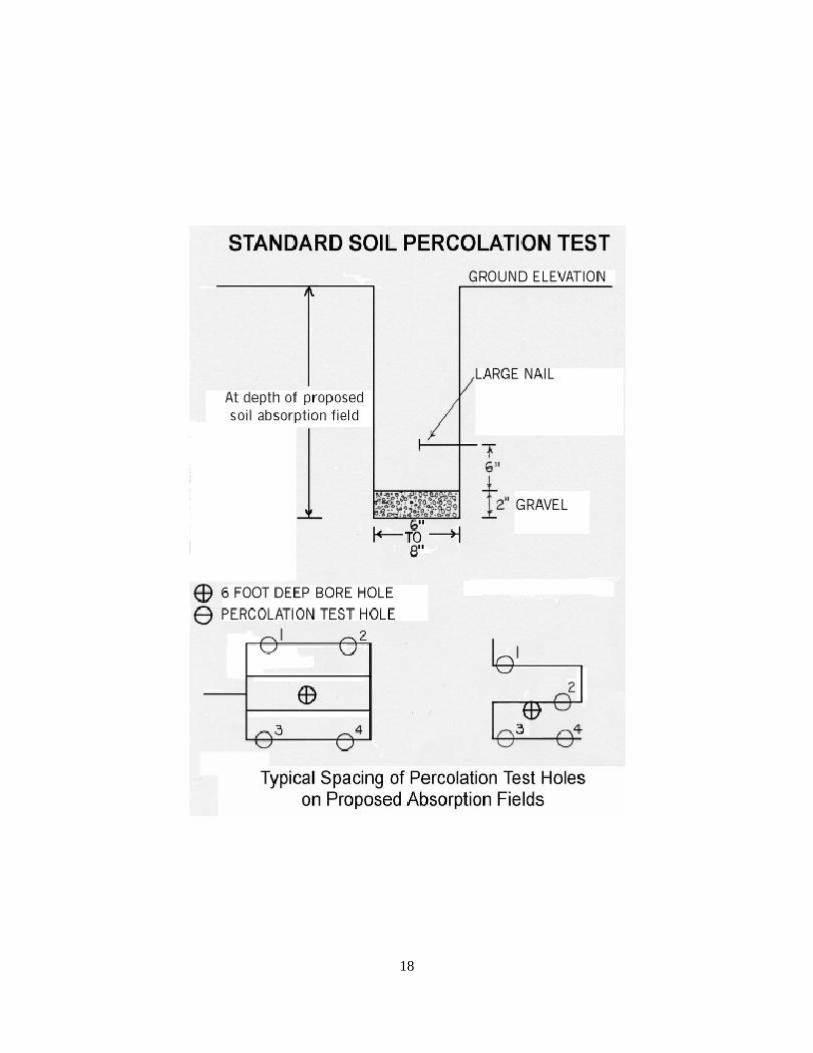
6.2.g. Roof drains, foundation drains, sump pumps, surface drains, or similar drains shall not connect to an individual sewage system. 6.2.h. The location of a septic tank or other treatment unit or disposal field shall not be under area to be paved, parking lots, driving surfaces, or any type of structure. 6.2.i. There shall be a minimum of three (3) feet between any portion of a standard soil absorption system and seasonal groundwater bedrock, and any other impermeable layer. 6.2.j. There shall be no standard septic tank soil absorption system installed in soils where percolation test results show an average percolation time of less than five (5) minutes per inch. 6.3. Site Evaluation. 6.3.a. The evaluation of a site for the installation of a soil absorption system, including absorption fields, serial systems, absorption beds, and others, shall include but not be limited to, percolation test results and evaluation of soils in a six (6) foot excavation. Percolation tests shall be performed according to the following: 6.3.a.1. A minimum of four (4) test holes shall be placed at equal distances over the entire absorption field site. If the results of the tests are reasonably close, it shall be considered an average test result. If the tests results show extreme variations, it may be considered necessary to relocate the field in a more suitable area; 6.3.a.2. Holes shall be bored to the depth of the proposed soil absorption field from six (6) to eight (8) inches in diameter at the site where the installation of the soil-absorption field is to take place; 6.3.a.3. The bottom and sides of the hole shall be scratched with a sharp pointed instrument or wire brush to remove any smeared soil surfaces that interfere with the absorption of water into the soil; 6.3.a.4. The loose dirt shall be removed from the bottom of the test holes and two (2) inches of gravel shall be placed into the holes to prevent sealing; 6.3.a.5. A nail or a marked measuring device shall be placed in the wall of each hole exactly six (6) inches above the level of the gravel; 6.3.a.6. The test hole shall be completely filled with water to ground level and maintained to a depth of at least twelve (12) inches for a minimum period of four (4) hours before beginning the percolation rate measurement. 6.3.b. Percolation Rate Measurement. After completing the requirements in Paragraph 6.3.a.1. - 6.3.a.6., the water depth shall be adjusted in the holes to the six (6) inch level. Determine how many minutes it takes for all of the water to absorb into the soil. The resulting time in minutes, divided by six (6), shall be the rate of fall or absorption per inch. 6.3.b.1. The average rate of fall for all test holes shall be determined by adding the rate of fall for each test hole together and dividing by the number of test holes. This figure is the average rate of fall per inch. See Table 64-47-L at the end of this rule. 6.3.b.2. If desired, an applicant may use an alternate test, if approved by the local health department.
4

6.3.b.3. Observation Hole. A hole shall be excavated six (6) feet deep in the center of the proposed soil absorption system area to evaluate the soil depth to bedrock and the seasonal water table. If slopes at the proposed site exceed fifteen percent (15%), the excavated observation hole shall be placed at the location of the lowest proposed trench of the system. Additional observation holes may be required when there are extreme variations in soil or geology in the test area. 6.3.b.4. Six (6) feet deep slit trenches of a specified length may be required in limestone geology to determine depth to bedrock. 6.4. Septic Tanks. 6.4.a. Liquid capacities for tanks serving single-family dwellings shall be in accordance with the following: 6.4.a.1. For four (4) or less bedrooms, the minimum tank capacity shall be one thousand (1,000) gallons; and 6.4.a.2. For each additional bedroom, the minimum tank capacity shall be two hundred fifty (250) gallons per bedroom. 6.4.b. When using a dual compartment tank or dual tanks, the volume ratio of the first compartment or tank to the second compartment or tank shall approximate two (2) to one (1). In a dual compartment tank, the connection between compartments shall be an elbow with a minimum diameter of four (4) inches, placed so that the invert at the partition is approximately sixteen (16) inches below the liquid level. 6.4.c. The construction of septic tanks may be of reinforced concrete, fiberglass or other watertight and durable materials approved by the Commissioner. All tanks shall meet the general requirements of Subdivision 6.4.g. of this rule, regardless of construction material. Septic tank construction shall comply with the following: 6.4.c.1. Precast Concrete Septic Tanks. Concrete used shall consist of at least six (6) bags of cement per yard of concrete mix or the equivalent, with a minimum compressive strength of four thousand (4000) pounds per square inch based on a twenty-eight (28) day compression test. Reinforcement shall be at least six (6) inch by six (6) inch mesh number ten (10) welded wire fabric or the equivalent. Aggregate used in the concrete shall be no larger than one (1) inch in size. There shall be vibrated concrete to minimize honey-combing. The sidewalls of the tanks shall be at least two and one-half (2½) inches in thickness. The top and bottom shall have a minimum thickness of four (4) inches. 6.4.d. The manufacturers of concrete septic tanks shall obtain approval from the Commissioner for the construction of and compliance with the Design Standards. 6.4.e. Metal Septic Tanks. Metal septic tanks shall not be approved due to their potential to leak into ground water. 6.4.f. Plastic and Fiberglass Tanks. The Commissioner shall approve plastic and fiberglass tanks. 6.4.g. General requirements for tanks shall be as follows: 6.4.g.1. The invert of the inlet pipe shall be a minimum of two (2) inches above the invert of the outlet pipe.
5

6.4.g.2. Inlets and outlets shall be a minimum of four (4) inches in diameter and equipped with a flexible watertight seal. 6.4.g.3. The inlet shall equip a cast-in-place or inserted baffle or a sanitary tee. The inlet baffle or sanitary tee shall extend to a minimum depth of six (6) inches, but to no more than twenty percent (20%) of the liquid depth. 6.4.g.4. The outlet shall equip a cast-in-place or inserted baffle or sanitary tee. The effluent baffle shall extend to at least thirty-five percent (35%) of the liquid depth, but to no more than forty percent (40%) of the liquid depth. 6.4.g.5. The top of the inlet and outlet baffles or tees shall extend at least six (6) inches above the flow line. 6.4.g.6. Minimum liquid depth shall be thirty (30) inches. 6.4.g.7 There shall be a minimum of nine (9) inches clearance above the liquid level. 6.4.g.8. The top of the tank, above the outlet, shall have embossing, imprinting, stenciling or other form of marking in an indelible and legible manner with the manufacturer's name, the liquid capacity and date of manufacture. 6.4.g.9. Access. There shall be adequate access to each compartment of the tank for inspection and cleaning. Both the inlet and outlet devices shall be accessible. When installing a septic tank at a depth greater than twelve (12) inches below grade, it shall be required to install an extended manhole riser to within twelve (12) inches of final grade. 6.4.g.10. All septic tanks shall have a four (4) inch gas tight inspection port that extends to the surface of the ground to measure sludge and scum accumulations. 6.5. The Standard Soil Absorption System. 6.5.a. The pipe for gravity distribution systems shall have a minimum diameter of four (4) inches. Pressure distribution systems may use smaller size pipe. 6.5.b. Pipe used in the construction of soil absorption fields shall conform to the ASTM Standards for wastewater piping. This includes, but is not limited to: 6.5.c. Plastic pipe ASTM - D 2729, D 2852, D 3350, D 2751, D 2836, D 3033, D 3034, D 3298, F 789. 6.5.d. The septic tank inlet and outlet piping shall be schedule forty (40) or the equivalent. This pipe shall span the tank hole excavation and rest on a minimum of two (2) feet of undisturbed soil. 6.5.e. Perforated pipe used in the construction of soil absorption systems shall have a minimum of two (2) rows of downward facing holes approximately ninety (90) degrees apart. 6.5.f. Aggregate used in the construction of a soil absorption field shall be washed gravel, crushed stone, or slag, one-half (½) to two and one-half (2½) inches in size, with a hardness of three (3) on the Moh scale of hardness. The field test for hardness is that the aggregate shall scratch a copper penny without leaving a residue.
6

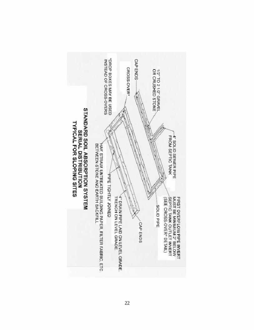
6.5.g. The installation of graveless soil absorption systems shall be in accordance with manufacturers’ specifications as approved by the Commissioner. 6.5.h. The construction of the standard soil absorption field with either level or sloping topography shall be in accordance with the following specifications: 6.5.h.1. The trenches shall be one (1) to three (3) feet wide with a maximum depth of thirty-six (36) inches and a minimum depth of eighteen (18) inches. 6.5.h.2. If distribution lines of greater than one hundred (100) feet are necessary, the connection of the inlet line shall be so that the lengths on either side of the connection shall not exceed one hundred (100) feet each. Absorption fields dosed by a pump or dosing siphon may utilize trenches of greater length, if reviewed and approved by the Commissioner. 6.5.h.3. There shall be a minimum of six (6) inches of aggregate placed in the bottom of the trench beneath the pipe, and a minimum of two (2) inches placed above the pipe. 6.5.h.4. The construction of the bottom of each trench and its distribution line shall be level. The construction of trenches shall be consistent with the topography and in such a manner so as to minimize the compaction or smearing of the sides and bottoms. Construction of the trenches shall not take place if the soil is so wet that it forms a "wire" instead of breaking apart when rolled between the hands. Construction shall not take place during rain or inclement weather that may interfere with or preclude correct construction procedures. 6.5.h.5. The surface of the aggregate shall have a cover of a minimum of three (3)inches of straw or hay, or one (1) layer of untreated building paper or filter fabric prior to backfilling. 6.5.h.6. There shall be a minimum of six (6) feet of undisturbed earth between the sidewalls of each trench. Additional separation may be a requirement in areas of severe topography and poor soil characteristics to avoid interaction between the trenches. 6.5.h.7. The design of soil absorption fields constructed in flat areas shall be to provide a closed continuous system or closed circuit design. 6.5.h.8. Performing the backfilling of the absorption field shall be in such a manner as to minimize compaction. There shall be a mound of backfill over the system to allow for settling and to promote run-off from the system. There shall be no grading to the absorption field construction area after backfilling. There shall be no backfilling if the ground is frozen. 6.5.h.9. The sewer line from the structure to the septic tank shall lay on a grade of not less than one-eighth (1/8) of an inch per foot (1%). 6.5.h.10. The installation of the absorption field shall be so that the invert of the absorption field piping is a minimum of eight (8) inches lower than the invert of the sewage tank outlet. 6.5.h.11. The construction of the standard soil absorption field in areas of sloping topography shall be in accordance with the following specifications: 6.5.h.11.A. Soil absorption fields constructed on sloping ground shall use a serial distribution system. This rule recommends the use of drop boxes;
7

6.5.h.11.B. The construction of soil absorption systems shall not be on ground with a slope in excess of twenty-five percent (25%); 6.5.h.11.C. The bottom of each trench and its distribution line shall be level; 6.5.h.11.D. There shall be a minimum of six (6) inches of ground cover over the gravel fill in each trench; and 6.5.h.11.E. The absorption trenches shall follow the approximate ground surface contours to minimize variation in trench depth. 6.5.h.12. Adjacent trenches shall connect with a relief line, cross over, or drop box arrangement in such a manner that each trench is completely filled with septic tank effluent to the full depth of the gravel before effluent flows to succeeding trenches. The construction of the relief line, cross-over, or drop box arrangement shall incorporate the following requirements: 6.5.h.12.A. The relief line or crossover shall be a solid four (4) inch sewer line with tight joints and with direct connection to the distribution lines or a drop box installation. 6.5.h.12.B. The construction of relief lines, cross-overs, and drop boxes shall not be in any location or manner where they shall be subject to damage during or following construction. An applicant shall mark the location of these relief lines, cross-overs, or drop boxes prior to backfilling to avoid damage from heavy equipment. The line shall rest on undisturbed earth with care given to carefully tamping the backfill. 6.5.h.12.C. The trench for the relief pipe or cross-over shall be no deeper than the top of the gravel of the trenches being connected. The line shall rest on undisturbed earth with care given to carefully tamping the backfill. An applicant shall exercise care in construction of the relief or cross-over line to insure that an undisturbed block of earth remains between the trenches. 6.5.h.12.D. The invert of the overflow pipe in the first relief or cross-over line should be at least two (2) inches lower than the invert of the septic tank outlet. 6.5.i. When servicing a structure other than a single-family dwelling, there shall be a reservation of land for the construction of two (2) standard soil-absorptions fields, each of adequate size to serve the proposed structure. 6.5.j. If the soil absorption field is greater than one thousand five hundred (1500) square feet in area, a siphon chamber or pump chamber may be required by the Commissioner to ensure even distribution of effluent. 6.5.k. Absorption fields over three thousand (3,000) square feet in total area shall include some form of dosing. 6.5.l. When a total field area over five thousand (5,000) square feet is necessary, the field shall be split into two (2) or more fields of approximately equal size. 6.6. Absorption Beds. 6.6.a. The construction of absorption beds shall only be when topography or space limitations prevent installation of a standard absorption field.
8

6.6.b. The size of absorption beds shall be to provide an area thirty percent (30%) greater than that calculated for a standard absorption field to make up for sidewall loss. 6.6.c. The installation of the piping distribution network within the bed shall be in such a manner that the location of the pipes are eighteen (18) to thirty-six (36) inches from the sides of the bed with a minimum of three (3) feet between pipes and a maximum of six (6) feet between pipes in a continuous or closed circuit design. Construction of the bed shall be in accordance with the general design and construction requirements of the standard absorption field. 6.6.d. Maximum depth of an absorption bed shall be thirty-six (36) inches, minimum depth shall be eighteen (18) inches. 6.7. Dual Soil Absorption Fields. 6.7.a. Use of dual absorption fields may receive approval if percolation rates are between sixty (60) minutes and ninety (90) minutes per inch. 6.7.b. Area reserved for absorption shall provide sufficient area for the replacement of dual soil absorption fields. 6.7.c. Construction of the dual absorption fields shall be in accordance with the dosing requirements of the standard soil absorption system, with a junction box or valving arrangement to provide for alternation of the fields. The size of each of the fields shall be in accordance with the percolation test results. Both fields shall be of the maximum sizing required for a sixty (60) minutes per inch rate. 6.8. Shallow and Elevated Soil Absorption Systems. 6.8.a. Due to the shallowness of many West Virginia soils, a soil absorption system shall often have to be shallow or the elevation shall be above the original ground surface to maintain the minimum distance above the seasonal high water table, rock table, or impermeable soil layer. The construction of a shallow or elevated system is permissible where there is a suitable layer of soil, sufficient room, and the natural slope is not excessive. Shallow and elevated soil absorption systems presently approved for use are: shallow fields, shallow beds, elevated fields and unique systems designed for specific situations. Shallow systems are similar to the standard absorption field and they may receive consideration for new residences. 6.8.b. Use of shallow and elevated systems using gravity distribution may receive approval under conditions where pervious rock table, an impermeable layer of any type, or seasonal water table is less than four and one-half (4½) feet of the ground surface, on either level topography or sites of up to approximately fifteen percent (15%) slope. When additional treatment precedes shallow or elevated fields, or designed as low pressure distribution systems, the Commissioner may waive the separation distance to an impermeable layer, or seasonal water table from three (3) feet to two (2) feet. Due to a potential for groundwater contamination, the depth to pervious rock table shall not be less than three (3)feet from any portion of the soil absorption system. Slope limitations of fifteen percent (15%) do not apply to low pressure systems. 6.9. Shallow Field.. 6.9.a. The construction of shallow systems shall in general be in accordance with the procedures and requirements for standard absorption fields. However, the depth of the trenches in natural ground may vary from twelve (12) to eighteen (18) inches. The space between trenches may vary from six (6) to twelve (12) feet, and the depth of cover material may vary from six (6) to twelve (12) inches, depending on the trench depth.
9

6.9.b. There shall be cover material placed prior to the construction of the trench system. 6.9.c. Topography of the site may be level, less than three percent (3%) slope, or up to fifteen (15) percent slope if using a serial type distribution system. 6.9.d. The percolation rate for design considerations shall be the rate recorded for the natural soil at installation depth. 6.9.e. Elevated Systems are systems installed at a depth of six (6) inches into the original ground and have a portion of the gravel or distribution piping in select fill above the original ground. All applicable provisions of Subsection 6.2 of this rule apply to elevated systems. 6.10. Individual Sewage Systems with Surface Water Discharge. 6.10.a. Individual systems with surface water discharge may receive consideration for approval under the following conditions: 6.10.a.1. To correct existing failures when other means of treatment and disposal have proven ineffective; and 6.10.a.2. On lots greater than two (2) acres in size that cannot qualify for standard or shallow soil absorption systems. All mechanical systems with surface water discharge shall have a perpetual maintenance agreement as approved by the Commissioner. 6.11. Individual Home Aeration Units. 6.11.a. Individual home aeration units shall be used only when there is a provision for additional treatment, such as soil absorption or other means of effluent disposal approved by the Commissioner. The Commissioner may require ownership, operation, and maintenance of a home aeration unit to be under the control of a public or private utility regulated by the Public Service Commission. 6.11.b. Individual home aeration units shall bear the NSF seal demonstrating conformance with NSF Standard 40 or other recognized testing agency approved by the Commissioner. 6.11.c. Individual home aeration units may receive approval providing an applicant meets the following criteria: 6.11.c.1. Shall have a perpetual maintenance agreement approved by the Commissioner; 6.11.c.2. May use Class I NSF plants or equivalent where there is surface water discharge; and 6.11.c.3. May use Class II NSF plants or equivalent where there is a provision for additional treatment. 6.12 Intermittent Surface Sand Filters. 6.12.a. Effluent from a home aeration unit may discharge to intermittent surface sand filters. 6.12.b. Effluent from a surface sand filter may discharge to a stream after disinfection in accordance with the regulations and requirements pertaining to surface discharge of waste water.
10

6.12.c. The design of intermittent surface sand filters preceded by a home aeration unit shall be on a filtration rate of ten (10) gallons per day per square foot. There shall be two (2) filters of design size to provide for alternation of operation. 6.12.d. Intermittent surface sand filters serving individual sewage systems shall have an insulated cover. 6.12.e. The intermittent surface sand filter shall receive dosing by either a pump or sewage siphon. 6.13. Composting Toilets. 6.13.a. Utilization of composting toilets may be only in conjunction with an approved grey water treatment and disposal system. 6.13.b. The design and construction of a composting toilet shall meet the requirements of NSF Standard 41. 6.14. Incinerating and Chemical Toilets. 6.14.a. Use of incinerating and chemical toilets may be only in conjunction with an approved grey water disposal system. 6.14.b. The design, construction, and application of incinerating or chemical toilets shall receive approval by the Commissioner. The use of chemical or incinerating toilets may receive approval by the Commissioner in emergency situations, temporary usage situations, or for recreational residences, or isolated residences. 6.15. Grey Water Disposal Systems. 6.15.a. Those houses served by a grey water disposal system shall have a house sewer of not more than two (2) inches in diameter. 6.15.b. Houses served by grey water disposal systems shall not have garbage disposal units connected to the grey water disposal system . 6.15.c. Manufactured grey water disposal systems shall receive approval by the Commissioner. 6.15.d. Non-commercial grey water disposal systems shall consist of the following: 6.15.d.1. A soil absorption field designed on the basis of a thirty percent (30%) reduction in water usage, and constructed in accordance with the design requirements for the standard soil absorption fields; and 6.15.d.2. A septic tank sized according to the following: 6.15.d.2.A. For four (4) or less bedrooms, the minimum tank capacity shall be one thousand (1,000) gallons; and 6.15.d.2.B. For each additional bedroom, the minimum tank capacity shall be two hundred fifty (250) gallons per bedroom.
11

6.16. Privies. 6.16.a. Every privy shall equip: 6.16.a.1. An earthen bottom pit or a watertight vault or other watertight receptacle with walls extending at least six (6) inches above ground level. 6.16.a.2. A crowned curb constructed of compacted earth or other suitable material, at least six (6) inches thick, extending from the top of the walls of the pit, vault, or receptacle, in all directions over the surface of the ground for a distance of eighteen (18) inches. 6.16.a.3. A riser that is fly tight when not in use. 6.16.a.4. There shall be an enclosed superstructure constructed with a vent pipe extending from the pit, vault, or receptacle to a point at least twenty-four (24) inches above the roof of the of the superstructure or through the wall of the superstructure. The vent shall have a screen to prevent the entrance of flies and other insects. 6.16.a.5. Privy pits may have an earthen bottom if: 6.16.a.5.A. The location of the privy is below and one hundred (100) feet or more from a groundwater supply or individual well, and its location is so that the disposal of any leaching from there is in a manner that does not create a nuisance or insanitary condition. 6.16.a.5.B. The pit is four (4) feet or less in depth and determined by the excavation of a seven (7) foot hole that rock or water table does not exist within three (3) feet of the bottom of the pit. 6.16.a.6. There shall be no privy located within twenty (20) feet of any dwelling, roadside cut, stream, establishment, or within ten (10) feet of any property line. 6.16.a.7. The construction and design of the privy superstructure, vault, pit or other type receptacle shall be such as to prevent access to the vault or receptacle and the contents thereof, by flies, rats, and wild or domestic animals. 6.16.a.8. Privy vaults, pits or receptacles shall have the contents removed as often as necessary to prevent creating a nuisance or unsanitary condition. 6.16.a.9. There shall be an approved grey water disposal system installed to serve those residences with indoor plumbing or running water for sinks and showers. For those residences without indoor plumbing, there shall be a shallow leach trench installed for disposal of grey water as approved by the Commissioner. 6.17. Recirculating Toilets. 6.17.a. Recirculating toilets and the piping for the toilets shall be separate from and not connected to the potable water system of any residence or other structure under any circumstances. There shall be color coded pipe used to facilitate inspection and maintenance of the installations. 6.17.b. Recirculating toilets shall: 6.17.b.1. Be installed and operated in accordance with the manufacturer's instructions; and 6.17.b.2. Be approved by the Commissioner before installation.
12

6.18. Self-Contained Excreta Disposal Systems. 6.18.a. The design of self-contained excreta disposal systems shall be so as to prevent flies, rats, and wild or domestic animals from having access to the contents thereof. 6.18.b. The construction of all fixtures, tanks, or receptacles shall be of impervious, easily cleanable material. 6.18.c. Tanks and receptacles shall: 6.18.c.1. Be watertight and vented to the outside air; 6.18.c.2. Be constantly supplied with sufficient amounts of an approved chemical agent to process and deodorize the contents thereof; and 6.18.c.3. Have the contents removed and the tank or receptacle thoroughly cleaned as often as necessary to prevent creating a nuisance, or an unsanitary condition. 6.19. Sewage Holding Tanks. 6.19.a. The approval of sewage holding tanks shall only be for new construction after a contract awarded for the development of a public or private sewage collection system or treatment facility, or both, to serve the proposed new construction. 6.19.b. A holding tank shall be watertight and constructed of the same materials and by the same procedures as a watertight septic tank. 6.19.c. The liquid capacity of the holding tank shall be sufficient to contain a one (1) week design flow from the facility it is to service. 6.19.d. The location of holding tanks shall be in an area readily accessible for pumping under all weather conditions and where accidental spillage during pumping presents the least hazard to public health. 6.19.e. The location of holding tanks shall be in accordance with the distance requirements established for septic tanks in Subsection 6.3 of this rule. 6.19.f. Construction and installation of the holding tank shall provide adequate access to the tank for pumping, cleaning and maintenance through manhole and cleanouts. 6.19.g. A holding tank installation shall equip an audiovisual high level alarm when the tank is approximately two-thirds (2/3) full and shall require pumping shortly. The location of the alarm shall be inside the facility served. 6.19.h. A contract with a licensed sewage tank cleaner with a valid permit for pumping and maintenance of the tank on a regular schedule shall be required. 6.19.i. A letter from a wastewater treatment plant owner accepting the pumpings shall be a requirement. This facility shall be approved by the Commissioner. There shall be an examination of the receiving wastewater treatment plant to ensure there shall be adequate treatment, and there shall be no effect on the normal operation of the wastewater treatment plant. 6.19.j. When it is necessary to protect the public health, the Commissioner reserves the right to require additional assurances before approving holding tanks.
13

6.20. Alternative and Experimental Sewer Systems. 6.20.a. The construction of alternative and experimental sewer systems may be where there is a suitable layer of soil, sufficient area and the natural slope is not excessive. 6.20.b. Alternative soil absorption systems presently approved for use are: shallow fields, soil absorption mounds, shallow beds, low pressure pipe systems, elevated fields, evapotranspiration systems and unique systems designed for specific situations. 6.20.c. Alternative soil absorption systems may receive consideration for new construction on lots two(2) acres and over providing soil and site limitations can be met. 6.21. Effluent Pumping for Individual Sewer Systems. 6.21.a. Pump type shall be non-clog submersible centrifugal effluent pumps or progressing cavity positive displacement pumps. 6.21.b. Pumps shall be readily removable and replaceable without dewatering the wet well. 6.21.c. The pump size should be to dose a soil absorption system two (2) to four (4) times a day. The recommended dosing cycle is twice a day, however, the dose shall be no more than seventy-five percent (75%) of the distribution pipe volume for all soil absorption systems using four (4) inch pipe. 6.21.d. The location of the pump shall be six (6) to eight (8) inches off the tank bottom to provide additional volume for sludge settlement. 6.21.e. The location of relays and electrical plug-ins or sockets shall not be inside the wet well or access manhole. The location of the devices must be above-ground in a weatherproof box or in the residence. 6.21.f. There shall be a high water alarm placed within the residence. 6.21.g. Pipe used for the distribution system, the force main, shall be PVC SDR 21, PVC SDR 26, or Schedule 40 1 1/4" to 2" diameter. 6.21.h. All parts of the distribution system, the manifold and laterals, shall slope slightly toward the inlet to avoid freezing and ponding of water in the system between dosing. 6.21.i. The installation of piping shall be below the frost line. 6.21.j. The wet well shall be watertight and constructed of materials that will not corrode. 6.21.k. The wet well shall have an access manhole of twenty four (24) inches or greater in diameter. The installation of the manhole shall be level with or above the ground surface and the cover secured. 6.21.l. The size of a wet well shall be to provide adequate volume not only for one day reserve capacity, but also for single dose capacity plus additional capacity to maintain minimum depth for operation. 6.21.m. The wet well tank shall be set lower than the septic tank to provide usage of maximum capacity of the wet well.
14
§64-47-10. Grease Traps. 10.1. There shall be grease traps for all restaurants and similar establishments where a large quantity of grease and fats in liquid wastes will occur. 10.2. The location of the external grease trap shall be within thirty (30) feet from the fixtures served. If meeting this distance requirement is not possible and thus, external grease traps are not possible due to existing conditions or physical limitations, the Commissioner may allow internal grease traps. 10.3. Only those plumbing fixtures into which the grease and fats are discharging shall connect to the grease trap. 10.4. The external grease trap shall be a minimum one hundred fifty (150) gallons capacity. Larger grease traps may be a requirement depending upon the loading. 10.5. The external grease trap shall be in an easily accessible place outside the building served. §64-47-4. Sewage Collection Systems. 4.2.s.4. Relation to Water Lines. 4.2.s.4.A. Horizontal Separation. Gravity or pressure sanitary sewers shall be at a minimum of ten (10) feet horizontally away from any existing or proposed water lines. However, if maintaining the ten (10) foot horizontal separation is not possible, the construction of the sewer and testing shall be as prescribed in Paragraph 4.2.s.5. of this rule. A sewer shall not be constructed closer than three (3) feet edge to edge to a water line. 4.2.s.4.B. Vertical Separation. When a gravity or pressure sanitary sewer must cross water lines, its construction shall be at an elevation so that the top of the sewer line is a minimum of eighteen (18) inches beneath the bottom of the water main. However, if meeting the eighteen (18) inch vertical separation requirement is not possible, then the construction of the sewer and testing shall be as prescribed in Paragraph 4.2.s.5. of this rule. 4.2.s.5. Special Construction Requirements. 4.2.s.5.A. Horizontal. In cases where water and gravity or pressure sanitary sewer lines must lay closer than ten (10) feet apart, the sewer line construction shall be a minimum of eighteen (18) inches lower than the water line and constructed of a pressure type pipe meeting requirements for water lines. The installation shall undergo hydraulic testing for a period of not less than twenty-four (24) hours and considered satisfactory if leakage is not more than 0.25 gallons per inch diameter of pipe per joint. In lieu of hydraulic testing, the sewer line can be air tested. The placement of the water line shall be upon an undisturbed earth shelf or bench. Backfilling to create the bench is not permissible. Maintaining maximum possible horizontal distance between the lines is a requirement. Where meeting these conditions is not possible, an applicant shall obtain written approval for a variance from the Commissioner. When placement of the lines is within five (5) feet of each other, each line shall have a metallic impregnated, permanent identification tape buried directly above it denoting "sewer line" or "potable water line."
15

4.2.s.5.B. Vertical. If maintaining a vertical clearance of eighteen (18) inches as specified in Subparagraph 4.2.s.4.B. of this rule is not possible, the location of the gravity or pressure sanitary sewer shall be so that it crosses between joints of the water line. Also, construction of the sewer line shall be so that it crosses under the water line at mid joint. The construction of the sewer shall be of a pressure type pipe meeting the requirements for water lines at the crossing. This rule requires maintaining a minimum vertical clearance of six (6) inches between the sewer and water lines. The construction of a gravity or pressure sanitary sewer line, or both, shall not be over the top of a water line. However, when meeting the standard vertical installation requirements is not possible, encase the sewer line so that the casing extends at least ten (10) feet on each side of the crossing. This rule requires maintaining a minimum vertical separation of eighteen (18) inches between the lines. §64-47-11. Administrative Due Process. Those persons adversely affected by the enforcement of this rule desiring a contested case hearing to determine any rights, duties, interests or privileges shall do so in a manner prescribed in the Rules of Procedure for Contested Case Hearings and Declaratory Rulings, 64 CSR 1. §64-47-12. Enforcement. This rule is enforced under W. Va. Code §§ 16-1-6, -9, -17, -18 and other applicable Code provisions.
16

TABLE 64-47-K Minimum Horizontal Separation Distances Between Soil Absorption Systems and Natural and Manmade Features
Distance Feature
10 feet Foundation drain upslope from disposal area.
20 feet Stream banks and open drainage features, whether manmade or natural.
20 feet Manmade cuts in soil and curtain drains.
20 feet Foundation drains downslope from disposal area.
50 feet Manmade cuts that intersect rock or shale.
100 feet Water supply springs and water supply wells.
50 feet Water Supply Cistern
TABLE 64-47-L Standard Septic Tank Soil Absorption System
Sizing for Single-Family Dwellings Percolation Test Results
(Average Time in Minutes Required for Water to Fall 1 Inch)
Minimum Area of Soil Absorption System
(Square Feet per Bedroom)
Less than 5 minutes Consult with local health department
5 - 30 minutes 300
31 - 60 minutes 400
over 60 minutes Consult with local health department
TABLE 64-47-M Single Absorption System Sizing for
Establishment Other than Single-Family Dwelling
Percolation Test Results Square Feet Per 1000 Gallons Sewage Per Day
Less than 5 minutes Consult with your local health department
5 - 10 minutes 1650
11 - 30 minutes 2500
31 - 45 minutes 2950
46 - 60 minutes 3300
Over 60 minutes Consult with your local health department
17
18

19

20

21
22

23

24

25

26

27

LOCAL HEALTH DEPARTMENTS
Barbour Co. Health Dept. Berkeley Co. Health Dept. Boone Co. Health Dept. Braxton Co. Health Dept. Brooke Co. Health Dept. Cabell-Huntington Health Dept. Calhoun Co. Service Center Clay Co. Health Dept. Doddridge Co. Health Dept. Fayette Co. Health Dept. Gilmer Co. Health Dept. Grant Co. Health Dept. Greenbrier Co. Health Dept. Hampshire Co. Health Dept. Hancock Co. Health Dept. Hardy Co. Health Dept. Harrison Co. Health Dept. Jackson Co. Health Dept. Jefferson Co. Health Dept. Kanawha-Charleston Health Dept. Lewis Co. Health Dept. Lincoln Co. Health Dept. Logan Co. Health Dept. Marion Co. Health Dept. Marshall Co. Health Dept. Mason Co. Health Dept. McDowell Co. Health Dept. Mercer Co. Health Dept. Mineral Co. Health Dept. Mingo Co. Health Dept. Monongalia Co. Health Dept. Monroe Co. Health Dept. Morgan Co. Health Dept. Nicholas Co. Health Dept. Wheeling-Ohio Health Dept. Pendleton Co. Health Dept. Pleasants Co. Service Center Pocahontas Co. Health Dept. Preston Co. Health Dept. Putnam Co. Health Dept. Beckley-Raleigh Health Dept. Randolph Co. Health Dept. Ritchie Co. Service Center Roane Co. Service Center Summers Co. Health Dept. Taylor Co. Health Dept. Tucker Co. Health Dept. Tyler Co. Health Dept. Upshur Co. Health Dept. Wayne Co. Health Dept. Webster Co. Health Dept. Wetzel Co. Health Dept. Wirt Co. Service Center Wood Co. Service Center Wyoming Co. Health Dept.
23 Walbash Ave., Philippi, WV 26416 800 So. Queen St., Martinsburg, WV 25401 P O Box 209, Courthouse, Madison, WV 25130 495 Old Turnpike Road, Sutton, WV 26601 632 Main St., Courthouse, Wellsburg, WV 26070 1336 Hal Greer Blvd., Huntington, WV 25701 P O Box 33, Grantsville, WV 26147 P O Box 36, Clay, WV 25043 Rt. 2, Box 54, West Union, WV 26456 202 Church St., Fayetteville, WV 25840 809 Mineral Road, Glenville, WV 26351 P O Box 608, Petersburg, WV 26847 P O Box 5910, Fairlea, WV 24902 HC 71 Box 9, Augusta, WV 26704 P O Box 578, New Cumberland, WV 26047 411 Spring Ave., Suite 101, Moorefield, WV 26836 116 So. Third St., Suite 201, Clarksburg, WV 26301 504 So. Church St., Ripley, WV 25271 44-1 Wiltshire Rd., Kearneysville, WV 25430 108 Lee St. E, PO Box 927 Charleston, WV 25323 125 Court St., P O Box 1750, Weston, WV 26452 P O Box 527, Hamlin, WV 25523 Courthouse Rm 203, P O Box 1316, Logan, WV 25601 300 2nd St., Fairmont, WV 26554 P O Box 429, Moundsville, WV 26041 216 Fifth St., Point Pleasant, WV 25550 P O Box 218, Wilcoe, WV 24895 Rt. 2, Box 382, Bluefield, WV 24701 Rt. 3, Box 3045, Keyser, WV 26726 Box 1096, Memorial Bldg., Williamson, WV 25661 453 Van Voorhis Rd., Morgantown, WV 26505 P O Box 590, Union, WV 24983 404 So. Green St., Berkeley Springs, WV 25411 One Stevens Rd., Summersville, WV 26651 1500 Chapline St Rm. 106, Wheeling, WV 26003 P O Box 520, Franklin, WV 26807 605 Cherry St. #3, St. Marys, WV 26170 Courthouse 900-10th Ave., Marlinton, WV 24954 425 E. Main St., Kingwood, WV 26537 4237 St. Rt. 34, Hurricane, WV 25526 1602 Harper Rd., Beckley, WV 25801 201 Henry Ave., Elkins, WV 26241 125 W. Main St., Harrisville, WV 26362 P O Box 909, Spencer, WV 25276 P O Box 898, Hinton, WV 25951 P O Box 15, Grafton, WV 26354 206 ½ - 3rd St., Parsons, WV 26287 425 So. 4th Ave., P O Box 273, Paden City WV 26159 15 N. Locust St., Buckhannon, WV 26201 P O Box 368, Wayne, WV 25570 324 Miller Mt. Dr, Webster Springs, WV 26288 425 So. 4th Ave., P O Box 273, Paden City WV 26159 P O Box 670, Elizabeth, WV 26143 211 – 6th St., Parkersburg, WV 26101 P O Box 1679, Pineville, WV 24874
(304) 457-1670(304) 267-7130(304) 369-7967(304) 765-2851(304) 737-3665(304) 523-6483(304) 354-6101(304) 587-4269(304) 873-1531(304) 574-1617(304) 462-7351(304) 257-4922(304) 645-1539(304) 496-9640(304) 564-3343(304) 538-6355(304) 623-9308 (304) 372-2634(304) 728-8415(304) 348-8050(304) 269-8218(304) 824-3330(304) 792-8630(304) 367-1746(304) 845-7844(304) 675-3050(304) 448-2174(304) 324-8836(304) 788-1321(304) 235-3570(304) 598-5131(304) 772-3064(304) 258-1513(304) 872-5329(304) 234-3682(304) 358-7565(304) 684-2461(304) 799-4154(304) 329-0096(304) 757-2541(304) 252-8532(304) 636-0396(304) 643-2917(304) 927-1480(304) 466-3388(304) 265-1288(304) 478-3572(304) 337-2001(304) 472-2810(304) 272-6761(304) 847-5483(304) 337-2001(304) 275-3131(304) 485-1416(304) 732-7941
28