western digital hard drive handling guide
TRANSCRIPT
For service and literature:
800.ASK.4WDC USA+31.20.4467651 Europe949.672.4WDC Mexicosupport.wdc.com Internetwww.westerndigital.com
Western Digital 20511 Lake Forest DriveLake Forest, California 92630
2579-001027-006 S0999 12/02
3.5Guide
i n c h
Western Digital
h a r d d r i v e h a n d l i n g

Information furnished by Western Digital is believed to be accurate and reliable. However, no responsibility is assumed by Western Digital for its use; nor for any infringement of patents or other rights of third parties which may result from its use. No license is granted by implication or otherwise under any patent or patent rights of Western Digital. Western Digital reserves the right to change specifications at any time without notice.
© 2002 Western Digital Technologies, Inc. All rights reserved.
Western Digital and the Western Digital logo are registered trademarks of Western Digital Technologies, Inc. Other marks may be mentioned herein that belong to other companies.
2579-001027-006 12/02
DrvHndGd.book Page 1 Sunday, December 22, 2002 3:42 PM

Contents
1 Overview
2 Introduction
Electrostatic Discharge (ESD) . . . . . . . . . . . . . . . . . . . . . . . . . . . . 2
General Handling Procedures . . . . . . . . . . . . . . . . . . . . . . . . . . . . 3
7 Receiving and Inspection of Hard Drive Shipments
Box Handling . . . . . . . . . . . . . . . . . . . . . . . . . . . . . . . . . . . . . . . . 7
Pallet Handling . . . . . . . . . . . . . . . . . . . . . . . . . . . . . . . . . . . . . . . 8
Removing Hard Drives from Shipping Containers . . . . . . . . . . . . 9
10 Installation
Testing . . . . . . . . . . . . . . . . . . . . . . . . . . . . . . . . . . . . . . . . . . . . 10
12 Hard Drive Transportation in Manufacturing Facility
14 Returning Western Digital Hard Drives
Repackaging Guidelines . . . . . . . . . . . . . . . . . . . . . . . . . . . . . . . 14
16 Appendix
Power Supply Requirements . . . . . . . . . . . . . . . . . . . . . . . . . . . . 16
Recommended Hard Drive Mounting Screw Information . . . . . 18
Examples of Low-Impact (non-ratcheting) Torque Screwdrivers . 18
ESD Products and Vendors. . . . . . . . . . . . . . . . . . . . . . . . . . . . . 18
Temperature Stabilization Chart . . . . . . . . . . . . . . . . . . . . . . . . . 19
ESD Voltages Generated by Common Materials and Actions . . 20
Drop Height Table . . . . . . . . . . . . . . . . . . . . . . . . . . . . . . . . . . . 20
Connector Mating Cycles . . . . . . . . . . . . . . . . . . . . . . . . . . . . . . 21
DrvHndGd.book Page 1 Sunday, December 22, 2002 3:42 PM
OVERVIEW - 1
OverviewThe 3.5-Inch Hard Drive Handling Guide illustrates the proper techniques for the receipt, storage, handling, and shipment of Western Digital hard drives.
Hard drives are precision instruments that read, write, and store information on spinning magnetic disks. Special care must be used in the handling of these drives to protect them from damage.
This guide is divided into the following sections for your convenience. Read the Introduction first, as it contains important precautions and handling procedures.
! Introduction! Receiving and Inspection of Hard Drive Shipments! Software Load and Hard Drive Test! Assembly of Hard Drives into Systems! System Test! Returning Western Digital Hard Drives! Appendix
CAUTION: Hard drives are typically damaged because of electrostatic discharge (ESD), rough handling, or shock and vibration. Always handle with care.
DrvHndGd.book Page 1 Sunday, December 22, 2002 3:42 PM

2 - INTRODUCTION
2 - INTRODUCTION
IntroductionHard drives are precision instruments that read, write, and store information on spinning magnetic disks. Special handling is required to protect hard drives from damage. Always read any section marked with a Caution note.
Electrostatic Discharge (ESD)Hard drives are typically damaged because of rough handling, shock and vibration, or electrostatic discharge (ESD). ESD can ruin a hard drive or incur hidden damage which may not show up until after the hard drive has left your factory.
ESD is caused by a variety of environmental and human factors. Dry air is more likely to contribute to ESD than humid air. Certain materials like polyester, carpet, hard rubber and vinyl found in shoes and floors, styrofoam cups, and cellophane tape have a tendency to build up a charge. The padding in your chair can build up a charge as you sit. See “ESD Voltages Generated by Common Materials and Actions” on page 20 for voltages generated by typical activites performed during the handling of hard drives.
CAUTION: ESD damage is usually invisible to the eye and may not be discovered until much later, either through intermittent performance or failure. By using the proper grounding procedures outlined in this manual and testing your grounding straps daily, you can reduce hard drive damage caused by ESD.
DrvHndGd.book Page 2 Sunday, December 22, 2002 3:42 PM

INTRODUCTION - 3
General Handling Procedures
Avoid extreme temperatures.
Do not drop, bump, shake, or otherwise jar a hard drive. Hold a hard drive by the sides.
Do not touch the printed circuit board assembly with your hand or tools.
DrvHndGd.book Page 3 Sunday, December 22, 2002 3:42 PM
4 - INTRODUCTION
4 - INTRODUCTION
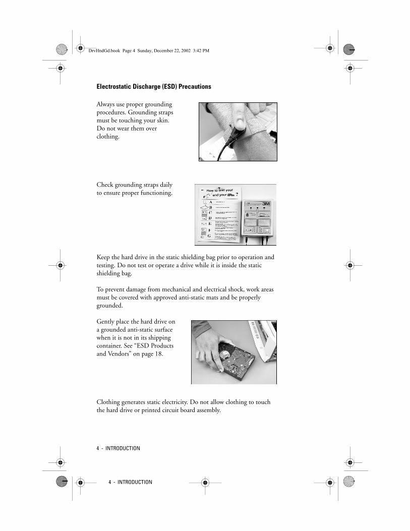
Electrostatic Discharge (ESD) Precautions
Always use proper grounding procedures. Grounding straps must be touching your skin. Do not wear them over clothing.
Check grounding straps daily to ensure proper functioning.
Keep the hard drive in the static shielding bag prior to operation and testing. Do not test or operate a drive while it is inside the static shielding bag.
To prevent damage from mechanical and electrical shock, work areas must be covered with approved anti-static mats and be properly grounded.
Gently place the hard drive on a grounded anti-static surface when it is not in its shipping container. See “ESD Products and Vendors” on page 18.
Clothing generates static electricity. Do not allow clothing to touch the hard drive or printed circuit board assembly.
DrvHndGd.book Page 4 Sunday, December 22, 2002 3:42 PM

INTRODUCTION - 5
Hard Drive Handling Precautions
Do not stack hard drives.
Do not stand hard drives on their sides.
Do not place anything on top of a hard drive.
CAUTION: Western Digital hard drives install easily. Never force a hard drive into a bay, hammer on the hard drive, or touch its printed circuit board assembly. Use caution when installing data and power connectors to avoid damaging pins. Double-check that all cables are properly connected.
DrvHndGd.book Page 5 Sunday, December 22, 2002 3:42 PM

6 - INTRODUCTION
6 - INTRODUCTION
When moving hard drives, do not roll carts over cracks or cords on the floor.
Place hard drives on the cart so that they do not come in contact with each other or the edges of the cart.
Western Digital hard drives have one to four small air filter holes on either the top or side of the drive enclosure. Do not obstruct or cover these holes with items such as stickers, and do not insert any objects into these holes.
DrvHndGd.book Page 6 Sunday, December 22, 2002 3:42 PM

RECEIVING AND INSPECTION OF HARD DRIVE SHIPMENTS - 7
Receiving and Inspection of Hard Drive ShipmentsExamine shipments carefully. Look for external damage and excessive moisture on boxes.
Box HandlingFollow guidelines for the shipping symbols on the side of the boxes.
Up Arrow - indicates the direction the top of the box must face.
Fragile Keep Dry - avoid exposing the box to moisture.
Cracked Glass - indicates the contents are breakable. Do not drop!
Umbrella - keep contents dry.
Stacking number - the maximum number of boxes to stack per pallet.
CAUTION: Stack boxes no more than five high on a single pallet. Leave the corner stiffeners on in case the pallets need to be stacked.
DrvHndGd.book Page 7 Sunday, December 22, 2002 3:42 PM

8 - RECEIVING AND INSPECTION OF HARD DRIVE SHIPMENTS
8 - RECEIVING AND INSPECTION OF HARD DRIVE SHIPMENTS
Pallet HandlingTransport carefully to storage area. Stack only two pallets high.
Stack Western Digital pallets together; do not stack with other manufacturers’ pallets. Never walk on top of the boxes.
Leave hard drives in their original packaging until testing or assembly takes place. To avoid condensation, allow hard drives ample time to reach room temperature before unpacking. Follow the “Temperature Stabilization Chart” on page 19 for a list of temperatures and the corresponding time periods that must expire prior to unpacking the drives.
DrvHndGd.book Page 8 Sunday, December 22, 2002 3:42 PM

RECEIVING AND INSPECTION OF HARD DRIVE SHIPMENTS - 9
Removing Hard Drives from Shipping Containers
Pick up the static shielding bag by the edge, making sure to avoid touching the hard drive inside the bag.
Hold the bag below the V-notch with one hand and tear off the top at the V-notch with the other hand.
Remove the hard drive by grasping it by its sides. Do not touch the circuit boards.
Carefully place the hard drive on approved anti-static padding only. See “ESD Products and Vendors” on page 18.
CAUTION: Leave the hard drive in its anti-static bag until it is ready to be installed.
DrvHndGd.book Page 9 Sunday, December 22, 2002 3:42 PM

10 - INSTALLATION
10 - INSTALLATION
InstallationObserve the following precautions and procedures when installing hard drives.
The parallel IDE cable length should not exceed 18 inches (45.72 cm). Serial ATA cable length should not exceed 39.37 inches (1 m). Check that the cable is in good physical condition.
Test the grounding device and straps daily.
TestingDo not use test racks with wheels as they are subject to movement.
Always use stationary racks or benches. When a system is on, avoid bumping or moving the test racks. This can cause head media damage.
DrvHndGd.book Page 10 Sunday, December 22, 2002 3:42 PM

INSTALLATION - 11
Remove the hard drive from the static shielding bag using the procedure outlined in the Electrostatic Discharge (ESD) Protection section. Do not test or operate a hard drive while it is inside the static shielding bag.
Confirm that the system power is off.
Carefully insert power and data connectors. Avoid excessive force.
Do not turn the system on until all power and connector cables are properly attached.
If the hard drive fails, make sure the failure is not due to faulty connections by replacing the connector and power cables and testing the hard drive again.
After turning the system off, wait 10 seconds for the hard drive to spin down and the heads to park before moving the hard drive. If not installing the hard drive immediately, return it to its static shielding bag.
CAUTION: Always use surge suppressors at test stations. Confirm that system power is off.
CAUTION: Do not use excessive force when installing data and power connectors.
00:10
DrvHndGd.book Page 11 Sunday, December 22, 2002 3:42 PM
12 - HARD DRIVE TRANSPORTATION IN MANUFACTURING FACILITY
12 - HARD DRIVE TRANSPORTATION IN MANUFACTURING FACILITY
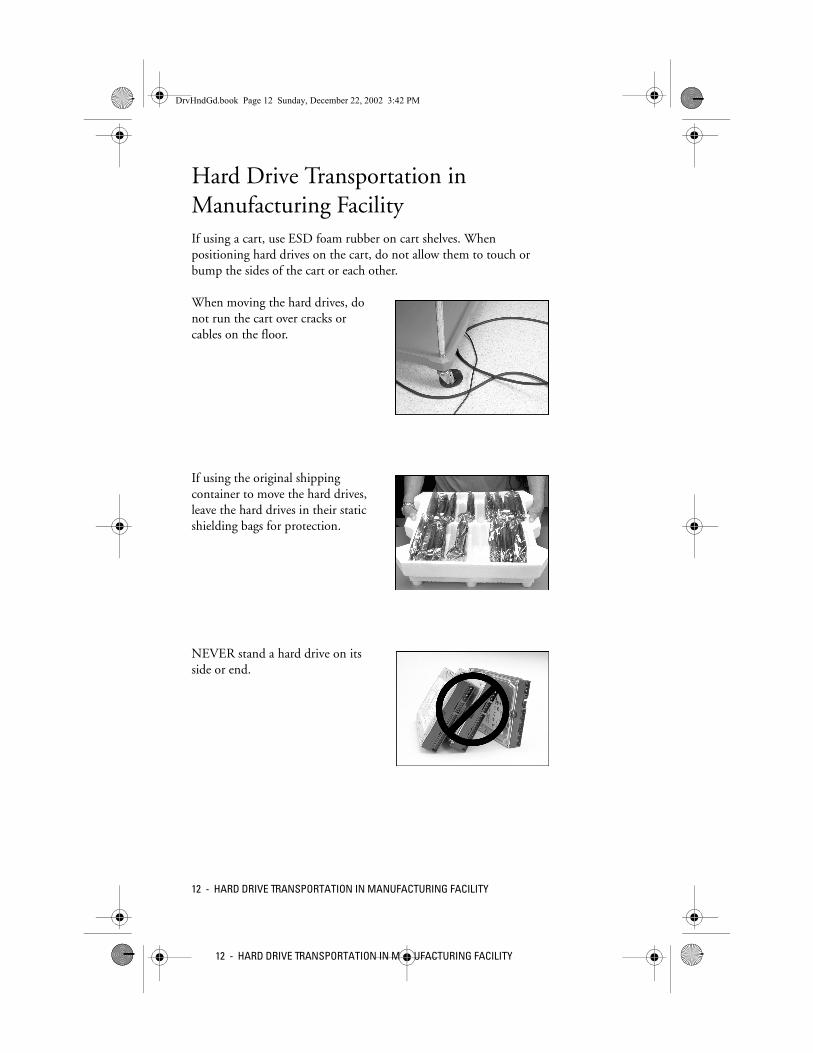
Hard Drive Transportation in Manufacturing FacilityIf using a cart, use ESD foam rubber on cart shelves. When positioning hard drives on the cart, do not allow them to touch or bump the sides of the cart or each other.
When moving the hard drives, do not run the cart over cracks or cables on the floor.
If using the original shipping container to move the hard drives, leave the hard drives in their static shielding bags for protection.
NEVER stand a hard drive on its side or end.
DrvHndGd.book Page 12 Sunday, December 22, 2002 3:42 PM

HARD DRIVE TRANSPORTATION IN MANUFACTURING FACILITY - 13
NEVER stack hard drives.
NEVER set anything on top of a hard drive.
Assembly tools must be well-maintained and properly calibrated. Use only low impact (non-ratcheting) power drivers for assembly. Screw torque specifications and examples of low impact tools are in the Appendix of this guide.
When installing into a hard drive bracket, avoid sudden, jerky movements. Also, do not force the hard drive in any way (no bumping, shoving, slapping, pounding, or other forms of coercion). Western Digital hard drives install easily.
CAUTION: NEVER force a hard drive into a bay, hammer on the hard drive, or touch its printed circuit board assembly. Double-check that all cables are properly connected.
DrvHndGd.book Page 13 Sunday, December 22, 2002 3:42 PM
14 - RETURNING WESTERN DIGITAL HARD DRIVES
14 - RETURNING WESTERN DIGITAL HARD DRIVES
Returning Western Digital Hard Drives
The following guidelines provide general information for Western Digital hard drive returns. For further information on returning hard drives, request the How to Return Western Digital Hard Drives Information Sheet, Literature Order Number S0198, from the Western Digital Literature Distribution Center.
If a hard drive is faulty and is under warranty, you can return it by first obtaining a Return Material Authorization (RMA) number and instructions for product return from Western Digital. The returned hard drive must meet the required conditions in order to return it to Western Digital for repair. The drive must be under warranty. It must not show signs of tampering. Moreover, it cannot arrive damaged upon its return to Western Digital because it was not properly repackaged according to the following repackaging guidelines.
Once you have determined that you can return the hard drive to Western Digital, you must be sure to package the hard drive according to Western Digital approved standards.
Repackaging Guidelines1. Remove and keep all add-on items, such as cables and brackets,
that are not included on the RMA. Western Digital is not responsible for them and cannot return them to you. Only items specified on the RMA are returned to you.
2. Handle the hard drive with care, holding it by the sides only.
3. Be sure it is a Western Digital hard drive. Check the hard drive label on the top surface of the hard drive.
4. Place the hard drive in the original static shielding bag prior to shipment. If the original bag is not available, please use an
CAUTION: Be sure to handle a failed hard drive as carefully as you would an operational one by strictly following proper handling procedures. By using these procedures, Western Digital can better determine the cause of the hard drive’s failure.
DrvHndGd.book Page 14 Sunday, December 22, 2002 3:42 PM

RETURNING WESTERN DIGITAL HARD DRIVES - 15
equivalent static shielding bag. Do not place anything inside the bag with the hard drive. If you need to attach a note, place it on the outside of the static shielding bag.
5. Use the original Western Digital packaging when available. If you do not have the original Western Digital packaging, use an outer carton made of corrugated cardboard. Do not use chipboard because it is not strong enough to withstand the rigors of transit.
6. Make sure the corrugated carton used is free from defects, structurally sound, and able to withstand the rigors of transit.
7. To protect the hard drive from shock, use a cushioning material. Foam is best and should be used on all sides of the hard drive inside the corrugated carton. You can substitute any of the following if foam is not available:
! Bubble wrap - wrap completely around the hard drive.
! Shredded newspaper - pack box full.
Packaging a single hard drive in one carton: Firmly cushion the hard drive on all sides to ensure that it cannot move inside the corrugated carton. This helps protect the hard drive in case it is dropped during shipping.
Packaging more than one hard drive in a carton: Make sure that all hard drives are cushioned individually and do not touch the sides of the box or each other. If using foam, surround the hard drives with a minimum of two inches of foam. Do not use peanuts or flowables as they do not support the hard drives from all sides during shipping.
8. Seal the carton firmly using adhesive back tape. Make sure all corrugated carton edges are sealed to prevent tearing.
For more repackaging information, visit the Western Digital Web site at support.wdc.com.
DrvHndGd.book Page 15 Sunday, December 22, 2002 3:42 PM

16 - APPENDIX
16 - APPENDIX
Appendix
Power Supply RequirementsIt is recommended that the power supply have a current rating for each output that is 5 percent greater than the maximum requirements of the drive in use.
Electrical Specifications—7200 RPM Hard Drives
Current Requirements and Power Dissipation
Power Management Commands
Voltage Ripple Frequency
+12 VDC ±10% 200 mV (peak to peak) max. 0 to 30 MHz
+5 VDC ±5% 100 mV (peak to peak) max. 0 to 30 MHz
Operating Mode RMS Current Power, Average1
12 VDC 5 VDC
Spinup 1.3A max 675 mA 19.0W
Read/Write 380 mA 800 mA 8.25W
Seek 675 mA 825 mA 12.25W
Operating Mode RMS Current1 Power, Average1
12 VDC 5 VDC
Idle (E1H) 370 mA 750 mA 8.25W
Standby (E0H) 15 mA 180 mA 1.10W
Sleep (E6H) 15 mA 75 mA 0.6W1 All values are typical (25°C, 5.0V, and 12V input) except where specified as maximum.Note: Current measurements cut off frequency at 1 kHz.
DrvHndGd.book Page 16 Sunday, December 22, 2002 3:42 PM

APPENDIX - 17
Electrical Specifications—5400 RPM Hard Drives
Current Requirements and Power Dissipation
Power Management Commands
Operating Mode RMS Current Power, Average1
12 VDC 5 VDC
Spinup 1.410A max 440 mA 14.0W
Read/Write 237 mA 650 mA 6.09W
Seek 600 mA 700 mA 10.7W
Operating Mode RMS Current1 Power, Average1
12 VDC 5 VDC
Idle (E1H) 220 mA 600 mA 5.64W
Standby (E0H) 28 mA 160 mA 1.21W
Sleep (E6H) 28 mA 100 mA 0.85W1 All values are typical (25°C, 5.0V, and 12V input) except where specified as maximum.Note: Current measurements cut off frequency at 1 kHz.
DrvHndGd.book Page 17 Sunday, December 22, 2002 3:42 PM

18 - APPENDIX
18 - APPENDIX
Recommended Hard Drive Mounting Screw Information
Examples of Low-Impact (non-ratcheting) Torque Screwdrivers
ESD Products and Vendors
Screw Type Recommended Torque
6-32 screws 5 in./lb, MAX 10
Electric Screwdrivers Maker - DenseiModel DLV-7339 (ESD Version)Distributor: Ingersoll-Rand(562) 777-0808
ESD Product Vendor
ESD Protective PaddingMicastat® PadsP/N 10385 or 10387)1/8-inch Pad
SVS Static Control Products231 Charcot Ave.San Jose, CA 95131(800) 870-8827
Metal Out Shielding BagESD Shielded Anti-static BagP/N 13035 or 13230 (zipper)
Highland™ Wrist StrapWith Ground CordP/N 2272
3M6801 Riverplace Blvd.Austin, TX 78726-9000(800) 328-1368
Heel Grounding AssemblyP/N 2059
DrvHndGd.book Page 18 Sunday, December 22, 2002 3:42 PM
APPENDIX - 19
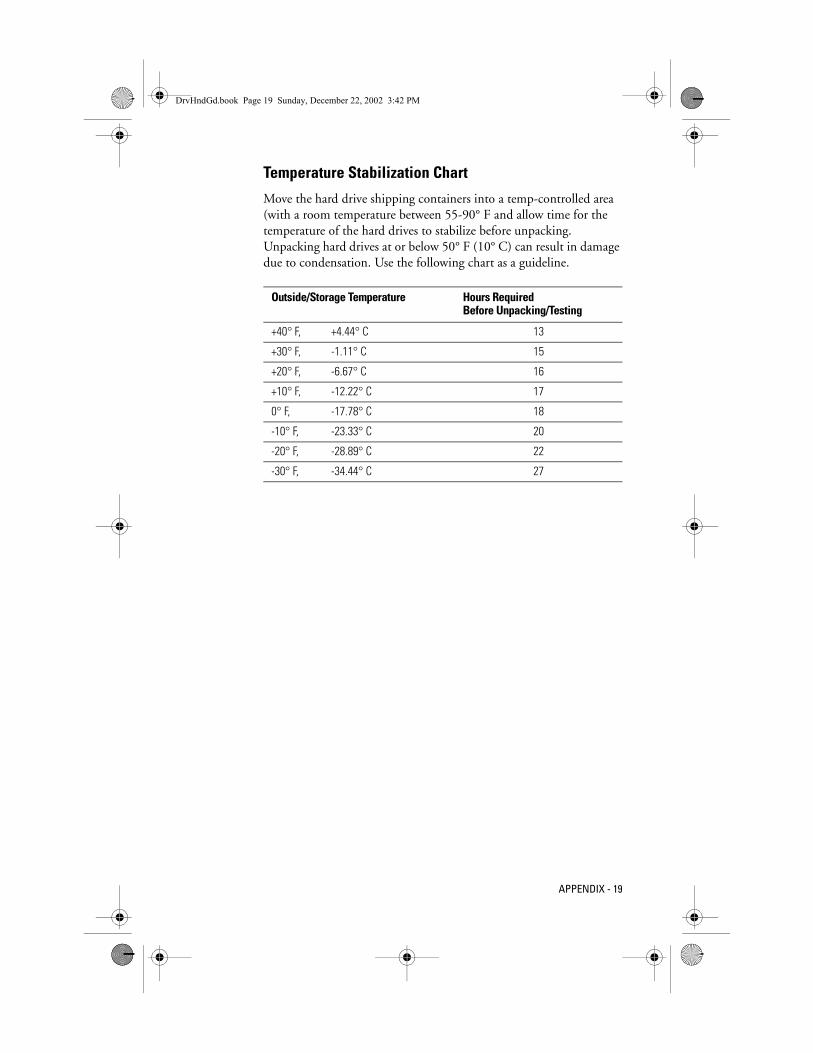
Temperature Stabilization Chart
Move the hard drive shipping containers into a temp-controlled area (with a room temperature between 55-90° F and allow time for the temperature of the hard drives to stabilize before unpacking. Unpacking hard drives at or below 50° F (10° C) can result in damage due to condensation. Use the following chart as a guideline.
Outside/Storage Temperature Hours Required Before Unpacking/Testing
+40° F, +4.44° C 13
+30° F, -1.11° C 15
+20° F, -6.67° C 16
+10° F, -12.22° C 17
0° F, -17.78° C 18
-10° F, -23.33° C 20
-20° F, -28.89° C 22
-30° F, -34.44° C 27
DrvHndGd.book Page 19 Sunday, December 22, 2002 3:42 PM

20 - APPENDIX
20 - APPENDIX
ESD Voltages Generated by Common Materials and Actions
Drop Height Table The shock rating of a hard drive is typically 200Gs (when the drive is in a non-operational state). The following table depicts the drop height versus Gs onto selected surfaces.
ESD Voltages
Means of ESD Generation 10 to 20 %Relative Humidity
65 to 90 %Relative Humidity
Walking across carpet 35,000 1,500
Walking over vinyl floor 12,000 250
Worker at bench 6,000 100
Common poly bag picked up from the bench
20,000 1,200
Work chair padded with polyurethane foam
18,000 1,500
Packing drives in foam lined box 21,000 1,200
Drop Height Gs - Force
Granite Surface
Concrete Floor
Formica Table
Anti-Static Foam
.5 in. / 12.7 mm 387 217 200 26
1.0 in. / 25.4 mm 595 457 310 37
2.0 in. / 50.8 mm 1,133 600 680 70
4.0 in. / 101.6 mm 1,795 1,040 1,050 267
DrvHndGd.book Page 20 Sunday, December 22, 2002 3:42 PM

APPENDIX - 21
Connector Mating Cycles
To avoid intermittent electrical connection problems, monitor and change the interface test cables on a regular basis. To maximize the number of reliable mating cycles, select extended life connectors where possible.
The following table shows connector life expectancy. Please note that these figures are just guidelines. Actual mating cycle life depends on specific connector materials, internal contact geometry, and other factors. Consult your connector vendor for specifications.
Connectors Plating and Configuration
Typical Mating Cycle Life Expectancy
Tin/Lead Plating 10 to 25 Connections
Standard Gold Plating (15µ - 40µ in.) 100 to 200 Connections
Extended Life with Thick Gold Plating (50m in. plus typical)*
500 to 1000 Connections
* Typically available only from connector direct suppliers as special orders.
DrvHndGd.book Page 21 Sunday, December 22, 2002 3:42 PM

For service and literature:
800.ASK.4WDC USA+31.20.4467651 Europe949.672.4WDC Mexicosupport.wdc.com Internetwww.westerndigital.com
Western Digital 20511 Lake Forest DriveLake Forest, California 92630
2579-001027-006 S0999 12/02
3.5Guide
i n c h
Western Digital
h a r d d r i v e h a n d l i n g