western electricity coordinating council modeling … 2017-11 report to...western electricity...
TRANSCRIPT

Page 1 of 15
Western Electricity Coordinating Council Modeling and Validation Work Group
Progress Report to Modeling Subcommittee
November 2017 The WECC Modeling and Validation Work Group (M&VWG) meeting were held in Salt Lake City, Utah on October 4‐5, 2017. The following Task Force Meetings were held before MVWG:
LMVTF – October 3 @ 1pm‐5pm MT
PPMVDTF ‐‐ October 4 @ 8am‐12pm MT
REMTF – October 4 @ 8am‐12pm MT At the M&VWG meeting, the following topics were discussed:
I. Next Meetings II. Load Modeling III. Renewable Energy Modeling IV. System Model Validation V. Generator Modeling, Testing, and Model Validation VI. HVDC Modeling VII. RAS and Relay Modeling VIII. NERC Updates IX. Approved Dynamic Model List X. Program Updates XI. Others
Page 2 of 15
I. NEXT MEETINGS AND WORKSHOPS
The next MVWG meeting is planned to be at Salt Lake City UT on January 24‐26, 2017. The MVWG meeting will be held in the afternoon of January 24th, 25th all day and morning of 26th.
II. LOAD MODELING
LMTF chair Irina Green (CAISO) provided an update of the LMTF work. A) CMPLDWG model
Following up with last MVWG meeting, the Load Modeling Task Force Chair, Irina Green from the California ISO, presented composite load model with distributed generation (cmpldwg) and discussed recommendation for its approval. It is becoming critical today to have dynamic model for large and growing amount of behind the meter solar PV generation. Netting this generation with load, as was done previously, or even modeling behind the meter generation at transmission buses provides less accurate study results than modeling it as a part of dynamic load. After discussed in the meeting, the group agreed that the composite load model with aggregated distributed generation should be approved as high priority. In order to get the model approval, in next several month, the LMTF will prepare evidence that show the cmpldwg model meet WECC Criteria for Acceptance of New Dynamic Models. Bill Price (GE) presented his latest on implementing the new DER_A model in the composite load model. DER_A is to be implemented in the existing composite load model with distribution generation ‐ cmpldwg initially, and later will be into “modular” format load model ‐ cmpldw2. The software changes have been made and the Beta version should be ready for testing by Nov. 30. It will be finalized when the REMTF finalizes the DER_A model (hopefully in January), and it will then be an easy change to cmpldw2 when it is time for that transition. B) Load model current status and next step
Dmitry Kosterev (BPA) summarized the load model development status and gave the future direction of the model development. With many years’ efforts, we are currently at the stage of 1st generation/phase II load models. Successful development of this model is a milestone in WECC. It captured load profile better than other load models in the past and provides more accurate system performance results. However, we also realized that this model is rigid with respect to model components. Compared with the load model development cycle, the load pattern changes much faster recently in last few years. More and more electronically connected loads (VFDs, ECMs, chargers) in the
Page 3 of 15
system, and also there is increasing percentage of distributed energy resources (PV solar, batteries) connected behind the meter in recent years. All of those changed load characteristics significantly. It requires us to think about to develop 2nd generation load model. The new load model should have more flexibility with respect to model components, should have consistent rules for model data interpretation and have efficient data management. The next step, LMTF will focus on the modular type model development/approval. In order to keep load model accurate/mature in the planning studies, several steps need to be taken for the model development as below. These steps not only apply to 2nd generation load model development, but also for continued supports of 1st generation for next serval years.
Load model structure research
Appliance industry outreach
Load composition model data
Load model validation and system impact studies
Tools for load model data management
Load monitoring C) Air conditioner model development
Anish Gaikwad (EPRI) presented the study results of the testing of air‐conditioners. The goal of
these tests was to refine the parameters of single‐phase air‐conditioners (Motor D). Two A/C units were tested. One is 2 Ton Trane unit scroll compressor, and another one is 4 Ton Armstrong unit scroll compressor. Both units are single speed no VFD. From previous cognition of single phase motor, we recognize that the motor will stall at certain level of voltage for certain length of time. The default value in WECC case is Vstall = 0.45 p.u. and Tstall = 2 cycles. One of the ERPI’s test confirmed that default Vstall and Tstall value, and also shows that they were temperatures independent. But another test shows that some of the single phase motors may drop out by the contactor opens at 0.5‐0.55 p.u. of voltage. They never stall. This behavior cannot be captured by the present Motor D model. Motor protection need further studied. D) CMPLDW Studies and Criteria
Irina Green (CAISO) presented dynamic stability study results with Phase 2 (single‐phase air conditioners stalling enabled) of the composite load model and comparison with Phase 1 (single‐phase air conditioners stalling disabled). There was a discussion of the WECC Transient Voltage Recovery Criteria. This criteria might have some ambiguous interpretation and is not very clear. It was decided to request the clarification of the criteria from WECC. E) Load Composition Modeling Update
Page 4 of 15
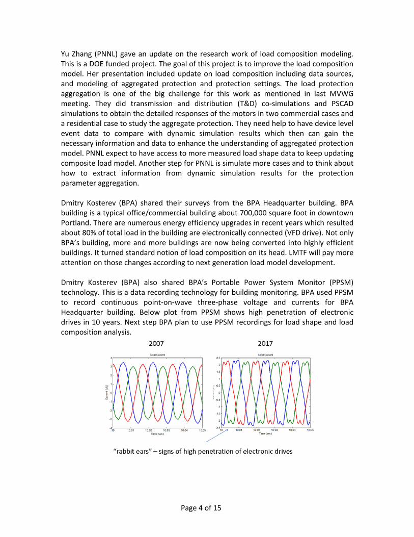
Yu Zhang (PNNL) gave an update on the research work of load composition modeling. This is a DOE funded project. The goal of this project is to improve the load composition model. Her presentation included update on load composition including data sources, and modeling of aggregated protection and protection settings. The load protection aggregation is one of the big challenge for this work as mentioned in last MVWG meeting. They did transmission and distribution (T&D) co‐simulations and PSCAD simulations to obtain the detailed responses of the motors in two commercial cases and a residential case to study the aggregate protection. They need help to have device level event data to compare with dynamic simulation results which then can gain the necessary information and data to enhance the understanding of aggregated protection model. PNNL expect to have access to more measured load shape data to keep updating composite load model. Another step for PNNL is simulate more cases and to think about how to extract information from dynamic simulation results for the protection parameter aggregation. Dmitry Kosterev (BPA) shared their surveys from the BPA Headquarter building. BPA building is a typical office/commercial building about 700,000 square foot in downtown Portland. There are numerous energy efficiency upgrades in recent years which resulted about 80% of total load in the building are electronically connected (VFD drive). Not only BPA’s building, more and more buildings are now being converted into highly efficient buildings. It turned standard notion of load composition on its head. LMTF will pay more attention on those changes according to next generation load model development. Dmitry Kosterev (BPA) also shared BPA’s Portable Power System Monitor (PPSM) technology. This is a data recording technology for building monitoring. BPA used PPSM to record continuous point‐on‐wave three‐phase voltage and currents for BPA Headquarter building. Below plot from PPSM shows high penetration of electronic drives in 10 years. Next step BPA plan to use PPSM recordings for load shape and load composition analysis.
Page 5 of 15
III. RENEWABLE ENERGY MODELING
REMTF chair Spencer Tacke (MID) provided an update of the SMVTF work. A) NERC Inverter Based Power Plant Model Validation Document Updates
Pouyan Pourbeik (PEACE) provided an overview of the NERC document (that Ryan Quint from NERC has been coordinating), the work completed to date, and the intent of the document. REMTF members have been contributing to this document, as originally the REMTF was starting to work on a similar wind model validation document, but it was determined that a lot of the same people from NERC working on this document would also be working on the REMTF document, so it was decided to work on just one document instead, the NERC document. The focus of this document is on how to validate any inverter‐based renewable generating resource, including wind, PV solar, and energy storage, in compliance with NERC Standards MOD‐025, MOD‐026, and MOD‐027. Progress has been good, with the intent to have it finalized by the end of 2017, and approved by NERC sometime in early 2018. The document in‐progress is currently available on the NERC website. Pouyan also encouraged anyone on the REMTF that wants to help with the remaining work on this document, to contact Ryan Quint at NERC. B) Experience with Field Testing of Type 3 WTGs
Pouyan Pourbeik (PEACE) discussed experience with wind power plant modeling and verification. He presented a detailed account of field testing five large wind power plants in order to build and validate the dynamic models for the plants using 2nd generation generic models. Several key insights are high‐lighted relative to the process and approach to model validation, including some unique circumstances for a few of these wind power plants, which are in close electrical proximity to each other. It is shown that these simplified models are able to match the field tests and yield reasonable and well‐behaved models for use in large scale stability studies. C) Distributed Energy Resource (DER_A) Model Status
At our March Meeting, Pouyan presented his prepared specification to the group for discussion and approval. During the group discussion at that time, several proposed revisions were discussed in detail, including addition of two time delays for frequency tripping, and a basic representation of the voltage source converter model for the network interface in order to reduce potential numerical problems for low SCR (short circuit ratio) systems. Also, the non‐symmetric option for partial tripping of the aggregated DG load was adopted.
Page 6 of 15
The revised specification was approved, and the four software vendors were asked to proceed with development of the Beta version of this meeting. Subsequently, Anish Gaikwad and Deepak Ramasubramanian of EPRI were asked to develop a testing protocol and proceed with Beta version software testing. They presented their results at the Meeting. Eleven different tests were developed. There were some observed inconsistencies in the response to voltage and frequency disturbance play‐in values displayed across the four software platforms. The inconsistencies varied from differences in ramp recovery of active and reactive power, frequency trip logic, level of load tripped for frequency and voltage disturbances, and spikes in measured bus frequency. The ensuing discussion between the software vendors and modelers revealed likely fixes to be: With these proposed changes, the software vendors will create new Beta versions and Deepak and Anish will then rerun the tests. The Group felt that these changes would eliminate most, if not all, the inconsistencies displayed across the software platforms. D) New Low Short‐Circuit Ratio System Generator/Convertor Model
Implementation of the REGC_B model is paralleling the development of the DER_A model. The software vendors have implemented beta versions and have been paralleling their testing as they have been testing the DER_A model. The final results of the Beta testing for DER_A will essentially dictate the completion date for implementation of the new REGC_B model. As you may recall, low SCR systems give numerical solution issues with the present current source inverter model (i.e., REGC_A), so there is a need to go to the voltage source inverter model, based on the IEEE paper by Deepak Ramasubramanian (EPRI), Ziwei Yu, Rajapandian Ayyanar, Vijay Vittal and John Undrill (ASU). Just three more parameters need to be added: Re, Xe, and Te. The software vendors had agreed to proceed with development of the BETA version of the model. Testing will proceed on low SCR systems simulations after that is completed, to verify the effectiveness of the new REGC_B model to help eliminate the numerical solution issues experienced with REPC_A in the past. E) Update on Weak Grid Operational (WGO) Control for Wind Turbines on Low SCR
System, Development of a New Model, REEC_D As Joergen Nielsen (SIEMENS Wind Power—Denmark) and Pouyan have been very busy with other priorities, it was noted that very little to no progress has been made on writing a specification for the new REEC_D model. Hope was expressed for a draft specification by early next year.
Page 7 of 15
As background, Hongtao Ma (formerly from SIEMENS‐Florida, now with NERC) had presented proposed changes to the wind turbine models SIEMENS had implemented to help eliminate the problems they had experienced when operating wind turbines in low SCR systems (low frequency oscillations and swings in power). The idea or concept is to hold the active current value down and allow it to recover after a fault with a controlled ramp, instead of allowing it to return in an almost instantaneous fashion. This thereby allows for some reactive current margin for more reactive current voltage support. Hongtao’s simulation results had shown a big improvement in response in low SCR systems. The REMTF agreed to write a specification for an additional module, called REEC_D. F) Suggestions for Enhancement of WECC 2nd Generation Wind Turbine Models to
Better Replicate the Dynamic Performance of Siemens Turbines At the March REMTF Meeting, Joergen Nielsen (Siemens Wind Power—Denmark) had presented the background of SIEMENS – Denmark’s various levels of modeling wind turbines. Joergen has some suggestions to improve the performance of our current 2nd Generation renewable wind turbine generator models, in regards to better matching their actual behavior of SIEMENS wind turbine generators. Some of the suggestions Joergen mentioned:
1. Active Power ramp up, instead of step change after fault clearing 2. Intermediate FRT (Fault Ride Through) method with reduced power and
voltage control for a certain time period (e.g., 3 seconds) 3. Asymmetric P‐Q Capability 4. FRT De‐Activation Hysteresis
However, as mentioned already in Item 6 above, Joergen and Pouyan have been very busy and their current priorities have not allowed either of them to pursue these possible enhancements to the 2nd Generation wind models. Joergen is hopeful that he will be freed up in the New Year to pursue these issues with Pouyan and others, and have some specific proposed changes by early 2018. G) Modeling of Inverter Momentary Cessation (NERC IRPTF updates)
Songzhe Zhu (CAISO) updated the work the NERC Inverter Based Resource Performance Task Force (IRPTF) Modeling and Simulation subgroup has been doing in trying to better match the actual responses of inverter‐ based PV systems in the field during the Aug. 16, 2016, a set of disturbance events in the Western Interconnection identified a potential risk of fault‐induced solar resource tripping. In the WECC base case, the PV electrical control was modeled by reec_b model. This model was a simplified reec_a model developed for PV electrical control. The issue is that this model has no capability to capture momentary cessation. It ignored Voltage_dip parameters and voltage error
Page 8 of 15
deadband (dbd1 & dbd2). To convert all the renewable generator models in the WECC basecase into regc_a/reec_a/repc_a is not straightforward. It would be parameter fitting with engineer judgement. IRPTF then developed an “In-run” epcl to simulate momentary cessation. It gets rid of the issues of changing any parameters provided by the GO, but significantly slows simulations. For the future permanent solution, the group decided to wait for the final results of the IRPTF work before proceeding with any model changes. One of another finding from this work is that some dynamic model errors in the WECC basecase for the renewable generation was found, which we didn’t realize in our dynamic data checking process. Some of them are the transducer time constant for terminal voltage shouldn’t be zero; wrong lhfrt settings; wrong plant controller flags; wrong MVA base; invalid reactive control models, etc. MVWG will add renewable data checking in the dynamic data error list. H) Update on Inertia Based (“Synthetic Inertia”) Fast‐Frequency Response for Wind
Turbine Generators Pouyan updated us on some recent considerations for this issue. Pouyan presented a proposed typical power versus time type of characteristic that would represent the “synthetic inertia” response. It is step‐wise linear, but he wonders how that would match up with G.E.’s current implementation of “synthetic inertia” in PSLF. It was noted that when the G.E. implementation hits its limits, the characteristic is piece‐wise linear, too. Pouyan indicated that EPRI may be available in 2018 to fund the starting of this work. As a background: One of the issues in implementing a generic model for this function is the differences between G.E.’s implementation and SIEMENS Wind / Enercon’s (and most other manufacturer’s) method of providing “synthetic inertia”. The G.E. approach is a kind of power shaping, while the others use a piece‐wise linear response. The question was: Can we model this generically? Also, will we need to keep track of wind speed and shaft speed to make the wind turbine model accurate, too, as both methods tap the rotating energy of the wind turbine generator to provide frequency support. So we need wind speed and rotor speed. The type 3 wind turbine model has rotor speed available, but not wind speed, while the type 4 model has neither. Hongtao Ma had previously indicated that that Hydro Quebec really requires this function in their wind turbines, and hence a generic model needs to be developed now. Hongtao asked if we could just implement the piece‐wise linear model as a start, and Pouyan had previously expressed his concern that someone from G.E. needed to provide input as to the implications of this type of generic model on the existing G.E. synthetic inertia method. The REMTF has been keeping this issue on its “to do” list, but it now seems some work may be starting on this topic in early 2018 through EPRI funding.

Page 9 of 15
IV. SYSTEM MODEL VALIDATION
SMVTF chair Slaven Kincic (PeakRC) provided an update of the SMVTF work. A) Model Validation Studies & NERC MOD‐033
Slaven Kincic (Peak RC) provided an update on SMVTF activities and talked about the current WECC wide system model validation procedure and then shared April 14th 2017 event validation that the Peak RC performed. April 14th 2017 event results system frequency drop to 59.830 Hz momentarily. WECC‐1 Remedial Action Scheme initiated tripping 1295 MW of generation in the Pacific Northwest. WECC Transfer Path 66 (COI) limited. This event and related case can be found from peakrc.org>Model>WSM Library. B) Updates on WECC Wide Events
Below are the time/date/frequency drop of the WECC wide system events. More detailed information can be found from Peak RC’s website. https://secure.peakrc.org/model/Pages/WSM-Model-Library.aspx Monday October 16, 2017 15:45 PDT – System frequency to 59.844 Hz Thursday September 14, 2017 21.04 PDT – System frequency to 59.818 Hz Monday September 11, 2017 17:24 PDT – System frequency to 59.911 Hz Friday September 9, 2017 20:46 PDT‐ System frequency to 59.878 Hz Tuesday August 8, 2017 03:08 PDT – System frequency to 59.827 Hz Saturday July 29, 2017 16:48 PDT – System frequency to 59.905 Hz Sunday July 30, 2017 18:55 PDT – System frequency to 59.875 Hz Friday June 23, 2017 14:45 PDT – System frequency to 59.760 Hz Monday June 19, 2017 14:43 PDT – System frequency to 59.853 Hz Friday June 16, 2017 05:14 PDT – System frequency to 59.668 Hz Thursday June 15, 2017 13:00 PDT –System frequency to 59.889 Hz Thursday June 8, 2017 07:47 PDT ‐ System frequency to 59.892 Hz Wednesday May 10, 2017 10:13 PDT‐ System frequency to 59.891 Hz Friday April 14, 2017 09:34 PDT‐ System frequency to 59.830 Hz Friday March 17, 2017 13:09 PDT‐ System frequency to 59.883 Hz Wednesday March 8, 2017 19:07 PST‐ System frequency to 59.783 Hz Tuesday March 7, 2017 19:23 PST ‐ System frequency to 59.850 Hz Friday March 3, 2017 20:06 PST‐ System frequency to 59.902 Hz Wednesday January 18, 2017 20:22 PST – System frequency to 59.890 Hz Saturday February 11, 2017 05:45 PST ‐ System frequency to 59.928 Hz Monday January 23, 2017 17:27 PST ‐ System frequency to 59.876 Friday January 20, 2017 00:01 PST ‐ System frequency to 59.857 Hz

Page 10 of 15
V. GENERATOR MODELING, TESTING, AND MODEL VALIDATION
PPMVDTF chair Steve Yang (BPA) provided an update of the PPMVDTF work.
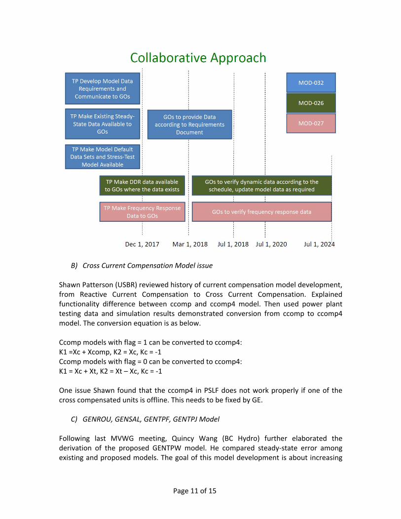
A) Wind and Solar Modeling Roadmap and Examples Dmitry Kosterev (BPA) reviewed NERC MOD 032, 025, 026, 027 standards requirements. Those standards require Generator Owner to provide data for Transmission Planner to develop steady‐state, dynamic and short‐circuit models. Blow couple of guidelines developed by WECC REMTF can be used for Planning Coordinator and Transmission Planner as a starting point for developing model requirements for wind power plants.
WECC Wind Power Plant Power Flow Modeling Guide https://www.wecc.biz/Reliability/WECC%20Wind%20Plant%20Power%20Flow%20Modeling%20Guide.pdf
WECC Wind Power Plant Dynamic Modeling Guide https://www.wecc.biz/Reliability/WECC%20Wind%20Plant%20Dynamic%20Modeling%20Guidelines.pdf Even with these guidelines, it is still difficult for TP to develop stable, reasonable and accurate model for grid simulations, because of the complexity of Wind Power Plant dynamic models. PPMVDTF proposed a collaborative roadmap to leverage collective expertise and experience of wind power plant operators, transmission planners, equipment manufacturers and industry experts. The key is to promote better collaboration while respecting compliance requirements of TPs and GOs – “Help you to help me”. We will develop a collaborative approach to wind power plant modeling and verification.
Page 11 of 15
B) Cross Current Compensation Model issue Shawn Patterson (USBR) reviewed history of current compensation model development, from Reactive Current Compensation to Cross Current Compensation. Explained functionality difference between ccomp and ccomp4 model. Then used power plant testing data and simulation results demonstrated conversion from ccomp to ccomp4 model. The conversion equation is as below. Ccomp models with flag = 1 can be converted to ccomp4: K1 =Xc + Xcomp, K2 = Xc, Kc = ‐1 Ccomp models with flag = 0 can be converted to ccomp4: K1 = Xc + Xt, K2 = Xt – Xc, Kc = ‐1 One issue Shawn found that the ccomp4 in PSLF does not work properly if one of the cross compensated units is offline. This needs to be fixed by GE.
C) GENROU, GENSAL, GENTPF, GENTPJ Model Following last MVWG meeting, Quincy Wang (BC Hydro) further elaborated the derivation of the proposed GENTPW model. He compared steady‐state error among existing and proposed models. The goal of this model development is about increasing

Page 12 of 15
transient‐state accuracy. Below is the proposed GENTPW model block diagram. The model structure still under review at this stage.
D) Turbine‐Governor h6e Model Update The initialization part of the h6e model has been changed to an explicit form that gives better assurance of a clean start. The latest code was sent to GE PSLF and Powerworld. John Undrill will forward the up‐to‐date code to PTI and TSAT as soon as he has it in the proper “non‐proprietary” format.
E) Generator Dynamic Model Testing Tool
Page 13 of 15
Yunzhi Cheng (ERCOT) introduced a dynamic model review tool. The tool developed in python. It uses a single power plant – infinite bus system to test the model individually. The tool has below features which can help Transmission Planners to check the generator dynamic model, especially user defined/generic renewable model. Voltage scan
ERUN
High voltage ride through
Low voltage ride through
Multi‐Low voltage ride through
Any other Voltage Response Test Frequency scan
GRUN
Any other Frequency Response Test SCR scan
Large Disturbance
Small Disturbance Yunzhi also shared model testing experiences.
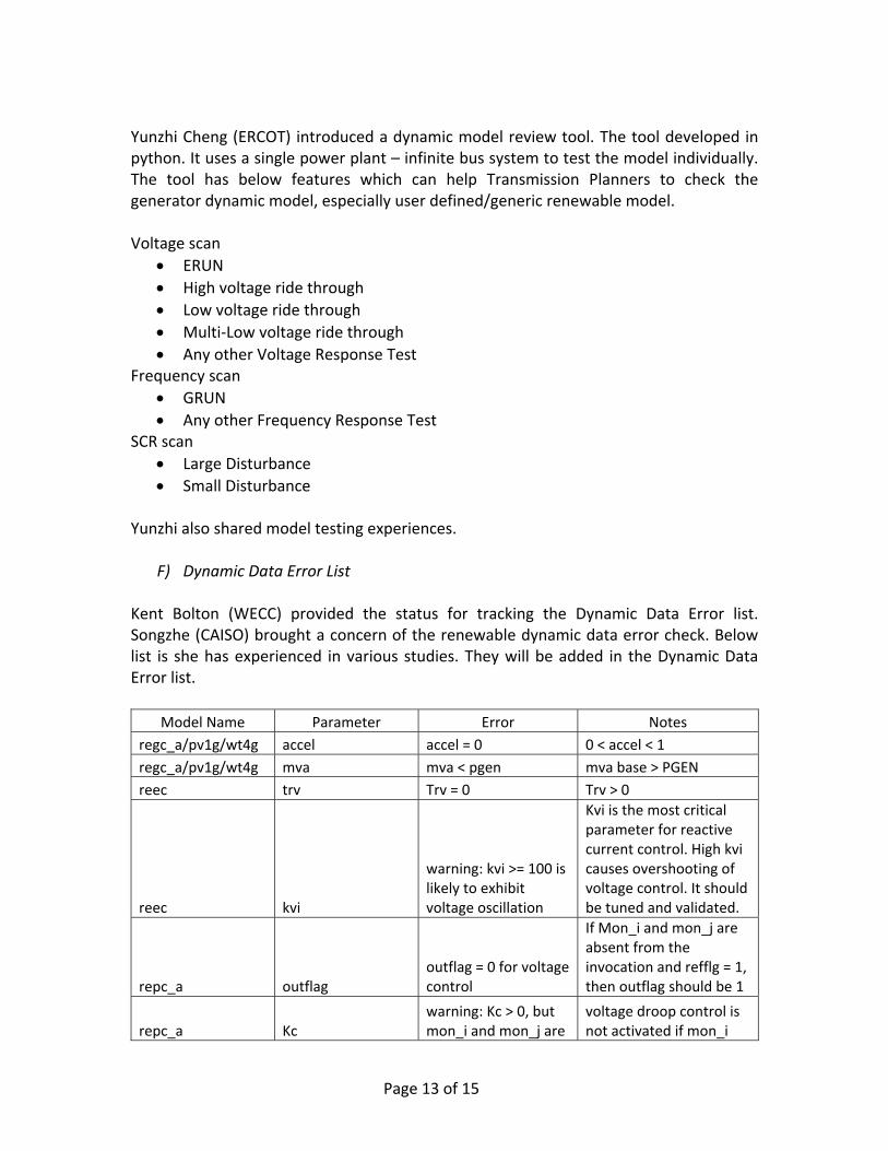
F) Dynamic Data Error List Kent Bolton (WECC) provided the status for tracking the Dynamic Data Error list. Songzhe (CAISO) brought a concern of the renewable dynamic data error check. Below list is she has experienced in various studies. They will be added in the Dynamic Data Error list.
Model Name Parameter Error Notes
regc_a/pv1g/wt4g accel accel = 0 0 < accel < 1
regc_a/pv1g/wt4g mva mva < pgen mva base > PGEN
reec trv Trv = 0 Trv > 0
reec kvi
warning: kvi >= 100 is likely to exhibit voltage oscillation
Kvi is the most critical parameter for reactive current control. High kvi causes overshooting of voltage control. It should be tuned and validated.
repc_a outflag outflag = 0 for voltage control
If Mon_i and mon_j are absent from the invocation and refflg = 1, then outflag should be 1
repc_a Kc warning: Kc > 0, but mon_i and mon_j are
voltage droop control is not activated if mon_i

Page 14 of 15
not provided in the invocation
and mon_j are not provided
reec and repc pfflag, vflag, qflag, refflag
The set of these four flags do not match any of the reactive power control options
lhfrt dftrp, dttrp not PRC‐024 compliant
dftrp is frequency change in Hz, not %
VI. HVDC MODELING
HVDCTF chair Pouyan Pourbeik provided an update on HVDC modeling development. Pouyan presented two years efforts of LCC dynamic model (chvdc2) development. The simple LCC planning model specification was issued in 2015. Presently, the four commercial software vendors GE PSLF, Siemens PTI PSS/E, PowerWorld Simulator and Power Tech Labs TSAT, have adopted the model. A simple benchmark test case system, based on the CIGRE benchmark case, was established for the testing the model. AC faults at both ends of the DC line as well as play‐in voltage and frequency waveforms were tested. Pouyan provided the test results from GE PSLF, PowerWorld Simulator and PowerTec Labs TSAT. Test results show that there is good agreement across all three platforms. The group reviewed test results and the model specification. Siemens PTI is hoping to get there testing completed soon to also release the model in PSS®E. The LCC dynamic model (chvdc2) was unanimously approved. For VSC dynamic model, the status is still under code‐debugging process for the concept implemented model being implemented by Pouyan. Once this is ready we will start the process of commercial software tool beta implementation and testing. For the high‐level documentation of PDCI and IPP, it is still work in progress and there is no draft to be shared at this moment. The draft document is presently under review by the HVDC owners and vendor. Once the review is complete, ABB will share the documents with WECC for WECC MVWG review and comments.
VII. RAS AND RELAY MODELING
The global line relay monitoring model specification approved at June MVWG meeting and has been implemented to commercial software platforms. This model gives Transmission Planners a capability to comply with NERC TPL standard requirement R4.1 and R4.3. However, there is still issue for the line relay applied to multi‐section, series‐
Page 15 of 15
compensated lines. Bill Price (GE) brought up this issue and proposed relay model changes. Modify global line relay (zlinw) to do the following when applied to multi‐section lines with series capacitors:
For zone 1, apply the reach fraction to the combined reactance of all line sections minus the reactance of any series capacitor at the near end of the line.
If zone 1 from one end or the other does not “see” all line faults, consider applying directional comparison blocking using zone 2 reach fraction times total Xl of the line and far‐end zone 3 reach equal to negative of the zone 1 reach. This trip function should only have sufficient delay to account for communication channel and detection delays.
If a line has more than one real line section separated by series capacitor(s), apply the relay logic to the combination of the line sections and intermediate capacitor(s).
Add zone 3 and add time delay for zone1 to zlinw. MVWG plan to form a relay task force to solve all the relay protection issues.
VIII. APPROVED DYNAMIC MODEL LIST
The latest version of the WECC Approved Dynamic Model Library available at WECC MVWG website. https://www.wecc.biz/Reliability/Approved%20Dynamic%20Models%20October%202017.pdf
IX. PROGRAM UPDATES
Software vendors updated programs.
X. OTHERS
Energy Storage Device Test Requirements was discussed in the meeting.