western star driver's manual
TRANSCRIPT

®WESTERN STAR
Driver’s Manual
STI-444-6A24-01242-000
IntroductionThis manual provides information needed to operateand understand the vehicle and its components.More detailed information is contained in the Owner’sWarranty Information for North America booklet andin the vehicle’s workshop and maintenance manuals.
Custom-built Western Star vehicles are equippedwith various chassis and cab components. Not all ofthe information contained in this manual applies toevery vehicle. For details about components in yourvehicle, refer to the chassis specification pages in-cluded in all new vehicles and to the vehicle specifi-cation decal located inside the vehicle.
For your reference, keep this manual in the vehicleat all times.
IMPORTANT: Descriptions and specifications inthis manual were in effect at the time of printing.Western Star Trucks reserves the right to dis-continue models and to change specifications ordesign at any time without notice and withoutincurring obligation. Descriptions and specifica-tions contained in this publication provide nowarranty, expressed or implied, and are subjectto revisions and editions without notice.
Environmental Concerns andRecommendationsWhenever you see instructions in this manual to dis-card materials, you should first attempt to reclaimand recycle them. To preserve our environment, fol-low appropriate environmental rules and regulationswhen disposing of materials.
Event Data RecorderThis vehicle is equipped with one or more devicesthat record specific vehicle data. The type andamount of data recorded varies depending on howthe vehicle is equipped (such as the brand of engine,if an air bag is installed, or if the vehicle features acollision avoidance system, etc.).
This vehicle is equipped with an event data recorder(EDR). The main purpose of an EDR is to recorddata in certain crash or near-crash situations, suchas air bag deployment or hitting a road obstacle, thatwill assist in understanding how a vehicle’s systems
performed. The EDR is designed to record data re-lated to vehicle dynamics and safety systems for ap-proximately 60 seconds. This data can help providea better understanding of the circumstances in whichcrashes and injuries occur. Data recorded includesthe following items:
• how various systems in the vehicle were oper-ating
• engine system information
• how far (if at all) the driver was depressing theaccelerator
• if the driver was depressing the brake pedal
• how fast the vehicle was traveling
NOTE: Data is not recorded by the EDR undernormal driving conditions. Personal data suchas name, gender, age, and crash location arenot recorded. However, other parties such aslaw enforcement could combine the EDR datawith the type of personally identifying data rou-tinely acquired during a crash investigation.
To read data recorded by an EDR, special equipmentis required, and access to the vehicle or the EDR isneeded. In addition to the vehicle manufacturer, otherparties that have the special equipment, such as lawenforcement, can read the information if they haveaccess to the vehicle or the EDR.
Emissions and Fuel EfficiencyComplianceThis vehicle must be regularly inspected and main-tained as indicated in the Western Star MaintenanceManual, and in the Pre- and Post-Trip Inspectionsand Maintenance chapter in this manual, in order tocontinue satisfactory performance and ensure cover-age of the vehicle under the manufacturer’s warranty.Many maintenance procedures ensure that the ve-hicle and engine continue to comply with applicableemissions standards. Maintenance procedures, usingcomponents engineered to comply with greenhousegas emissions and fuel efficiency regulations, may beperformed by an authorized Daimler Trucks NorthAmerica dealer, an independent outlet, or the vehicleowner or operator.
The vehicle owner is responsible for determining thesuitability of replacement components to maintain
Foreword
STI-444-6 (12/15)A24-01242-000
Printed in U.S.A.
compliance with federal and local jurisdictional regu-lations. Components including, but not limited to,tires, cab/sleeper side extenders, chassis fairings,bumper, hood, vehicle speed limiters, and idle reduc-tion timers are specifically designed and manufac-tured to exacting standards for regulatory fuel effi-ciency and greenhouse gas emissions compliance. Itis important that these components are always re-placed with components that meet or exceed the per-formance of the originally installed components.
Customer Assistance CenterHaving trouble finding service? For over-the-roadbreakdown assistance, customer concerns, literaturerequests, and the location of the nearest dealer, call1-866-850-STAR (7827). Call night or day, weekdaysor weekends. Our people are knowledgeable, profes-sional, and committed to following through to helpyou keep your truck moving.
Reporting Safety DefectsIf you believe that your vehicle has a defect whichcould cause a crash or could cause injury ordeath, you should immediately inform the NationalHighway Traffic Safety Administration (NHTSA) inaddition to notifying Western Star Trucks.
If the NHTSA receives similar complaints, it mayopen an investigation, and if it finds that a safetydefect exists in a group of vehicles, it may order arecall and remedy campaign. However, NHTSAcannot become involved in individual problemsbetween you, your dealer, or Western Star Trucks.
To contact NHTSA, you may call the VehicleSafety Hotline toll-free at 1-888-327-4236 (TTY:1-800-424-9153); go to www.safercar.gov; orwrite to: Administrator, NHTSA, 1200 New JerseyAvenue, SE, Washington, DC 20590. You can alsoobtain other information about motor vehicle safetyfrom www.safercar.gov.
Canadian customers who wish to report a safety-related defect to Transport Canada, Defect Investi-gations and Recalls, may telephone the toll-freehotline 1-800-333-0510, or contact TransportCanada by mail at: Transport Canada, ASFAD,
Place de Ville Tower C, 330 Sparks Street, Ot-tawa, Ontario, Canada K1A 0N5.
For additional road safety information, please visitthe Road Safety website at: www.tc.gc.ca/roadsafety.
© 2001–2016 Daimler Trucks North America LLC. All rights reserved. Daimler Trucks North America LLC is a Daimler
company.
No part of this publication, in whole or part, may be translated, reproduced, stored in a retrieval system, or transmittedin any form by any means, electronic, mechanical, photocopying, recording, or otherwise, without the prior written per-mission of Daimler Trucks North America LLC. For additional information, please contact Daimler Trucks NorthAmerica LLC, Service Systems and Documentation, P.O. Box 3849, Portland OR 97208–3849 U.S.A. or refer towww.Daimler-TrucksNorthAmerica.comand www.WesternStarTrucks.com.
Foreword

ContentsChapter Page
Introduction, Environmental Concerns and Recommendations,Event Data Recorder, Emissions and Fuel Efficiency Compliance,Customer Assistance Center, Reporting Safety Defects . . . . . . . . . . . . . . . . . . . . Foreword
1 Vehicle Identification . . . . . . . . . . . . . . . . . . . . . . . . . . . . . . . . . . . . . . . . . . . . . . . . . . . . . . 1.12 Vehicle Access . . . . . . . . . . . . . . . . . . . . . . . . . . . . . . . . . . . . . . . . . . . . . . . . . . . . . . . . . . 2.13 Instruments . . . . . . . . . . . . . . . . . . . . . . . . . . . . . . . . . . . . . . . . . . . . . . . . . . . . . . . . . . . . . 3.14 Driver Controls . . . . . . . . . . . . . . . . . . . . . . . . . . . . . . . . . . . . . . . . . . . . . . . . . . . . . . . . . . 4.15 Climate Controls . . . . . . . . . . . . . . . . . . . . . . . . . . . . . . . . . . . . . . . . . . . . . . . . . . . . . . . . . 5.16 Seats and Restraints . . . . . . . . . . . . . . . . . . . . . . . . . . . . . . . . . . . . . . . . . . . . . . . . . . . . . 6.17 Cab and Sleeper Features . . . . . . . . . . . . . . . . . . . . . . . . . . . . . . . . . . . . . . . . . . . . . . . . . 7.18 Electrical System . . . . . . . . . . . . . . . . . . . . . . . . . . . . . . . . . . . . . . . . . . . . . . . . . . . . . . . . 8.19 Engine Starting, Operation, and Shutdown . . . . . . . . . . . . . . . . . . . . . . . . . . . . . . . . . . . . 9.1
10 Optional Engine Systems . . . . . . . . . . . . . . . . . . . . . . . . . . . . . . . . . . . . . . . . . . . . . . . . . 10.111 Emissions and Fuel Efficiency . . . . . . . . . . . . . . . . . . . . . . . . . . . . . . . . . . . . . . . . . . . . . 11.112 Brake Systems . . . . . . . . . . . . . . . . . . . . . . . . . . . . . . . . . . . . . . . . . . . . . . . . . . . . . . . . . 12.113 Steering System . . . . . . . . . . . . . . . . . . . . . . . . . . . . . . . . . . . . . . . . . . . . . . . . . . . . . . . . 13.114 Manual Transmissions and Clutch . . . . . . . . . . . . . . . . . . . . . . . . . . . . . . . . . . . . . . . . . . 14.115 Automated and Automatic Transmissions . . . . . . . . . . . . . . . . . . . . . . . . . . . . . . . . . . . . 15.116 Drive Axles . . . . . . . . . . . . . . . . . . . . . . . . . . . . . . . . . . . . . . . . . . . . . . . . . . . . . . . . . . . . 16.117 Fifth Wheels . . . . . . . . . . . . . . . . . . . . . . . . . . . . . . . . . . . . . . . . . . . . . . . . . . . . . . . . . . . 17.118 Trailer Couplings . . . . . . . . . . . . . . . . . . . . . . . . . . . . . . . . . . . . . . . . . . . . . . . . . . . . . . . . 18.119 Headlight Aiming . . . . . . . . . . . . . . . . . . . . . . . . . . . . . . . . . . . . . . . . . . . . . . . . . . . . . . . . 19.120 Vehicle Appearance and Care . . . . . . . . . . . . . . . . . . . . . . . . . . . . . . . . . . . . . . . . . . . . . 20.121 In An Emergency . . . . . . . . . . . . . . . . . . . . . . . . . . . . . . . . . . . . . . . . . . . . . . . . . . . . . . . 21.122 Pre- and Post-Trip Checklists . . . . . . . . . . . . . . . . . . . . . . . . . . . . . . . . . . . . . . . . . . . . . 22.123 Pre- and Post-Trip Inspections and Maintenance . . . . . . . . . . . . . . . . . . . . . . . . . . . . . . 23.1
Index . . . . . . . . . . . . . . . . . . . . . . . . . . . . . . . . . . . . . . . . . . . . . . . . . . . . . . . . . . . . . . . . . . I.1

1
Vehicle IdentificationComponent Information Label . . . . . . . . . . . . . . . . . . . . . . . . . . . . . . . . . . . . . . . . . . . . . . . . . . . . . . . 1.1Federal Motor Vehicle Safety Standard Labels . . . . . . . . . . . . . . . . . . . . . . . . . . . . . . . . . . . . . . . . . . 1.1Canadian Motor Vehicle Safety Standard Labels . . . . . . . . . . . . . . . . . . . . . . . . . . . . . . . . . . . . . . . . 1.1Component GWR Label . . . . . . . . . . . . . . . . . . . . . . . . . . . . . . . . . . . . . . . . . . . . . . . . . . . . . . . . . . . . 1.1Emissions Labels . . . . . . . . . . . . . . . . . . . . . . . . . . . . . . . . . . . . . . . . . . . . . . . . . . . . . . . . . . . . . . . . . 1.2

Component Information LabelNOTE: Labels shown in this chapter are ex-amples only. Actual specifications may vary fromvehicle to vehicle.
The component information label lists the vehiclemodel, identification number, and major componentmodels. It also lists the major assemblies and instal-lations shown on the chassis specification sheet.One copy of the component information label is at-tached to the inside of the glove box; another copy isinside the rear cover of the Owner’s Warranty Infor-mation for North America booklet. An illustration ofthe label is shown in Fig. 1.1.
Federal Motor Vehicle SafetyStandard LabelsNOTE: Due to the variety of Federal Motor Ve-hicle Safety Standard (FMVSS) certification re-quirements, not all of the labels shown will applyto your vehicle.
The FMVSS labels are attached to the driver-sidedoor frame B-pillar, as shown in Fig. 1.2. Tractorswith or without fifth wheels purchased in the U.S. arecertified by means of a certification label. SeeFig. 1.3.
Trucks built without a cargo body that are intendedfor service in the U.S. have an incomplete vehiclecertification label attached by the final-stage manu-facturer. See Fig. 1.4. This label will be attached tothe incomplete vehicle document included with thevehicle, and certifies that the vehicle conforms to allapplicable FMVSS regulations in effect on the date ofcompletion.
Canadian Motor Vehicle SafetyStandard LabelsIn Canada, tractors with fifth wheels are certified bymeans of a statement of compliance label with theCanadian National Safety Mark attached to thedriver-side door frame B-pillar. See Fig. 1.5.
Trucks built without a cargo body and tractors builtwithout a fifth wheel that are intended for service inCanada have an incomplete vehicle certification label(similar to Fig. 1.4) attached to the driver-sideB-pillar. After completion of the vehicle, a completecertification label must be attached by the final-stagemanufacturer to certify that the vehicle conforms toall applicable Canada Motor Vehicle Safety Standard(CMVSS) regulations in effect on the date ofcompletion.
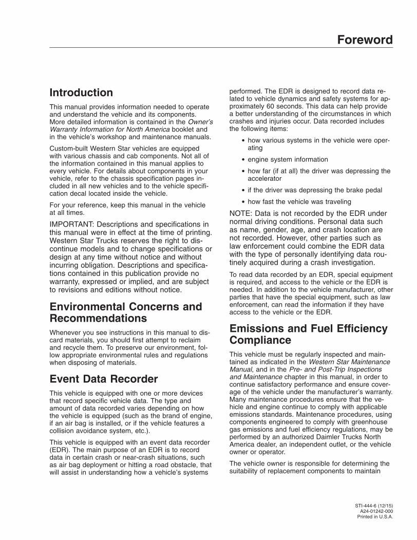
Component GWR LabelThe component GWR label is located on the A-pillarof the driver-side door frame. The label providesmaximum GWR ratings for each component.
See Fig. 1.6 for a typical component GWR label.
06/28/2011 f080173
Fig. 1.1, Component Information Label
06/28/2011
1
2
f602081
1. Certification Label2. Noise Emission Label
Fig. 1.2, Label Locations
Vehicle Identification
1.1

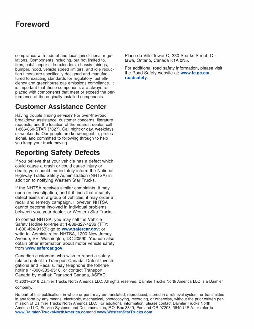
Emissions LabelsAftertreatment System IndicatorsLabelEngines and vehicles manufactured after December31, 2006 and domiciled in the U.S. or Canada arerequired to meet all EPA regulations effective as ofthe vehicle build date, and are equipped with anemission aftertreatment system (ATS). Vehicles do-miciled outside of the U.S. and Canada may nothave aftertreatment equipment, depending upon localstatutory emissions guidelines. See Table 1.1.
A warning label on the driver-side visor contains im-portant warning indicators in the instrument clusterthat pertain to the ATS. See Fig. 1.7 or Fig. 1.8.
It is a violation of U.S. federal law to alter exhaustplumbing, ATS, or other components in any way thatwould bring the engine/vehicle out of compliance withcertification requirements [Ref: 42 U.S.C. S7522(a)
(3)]. It is the owner’s responsibility to maintain thevehicle so that it conforms to EPA regulations.
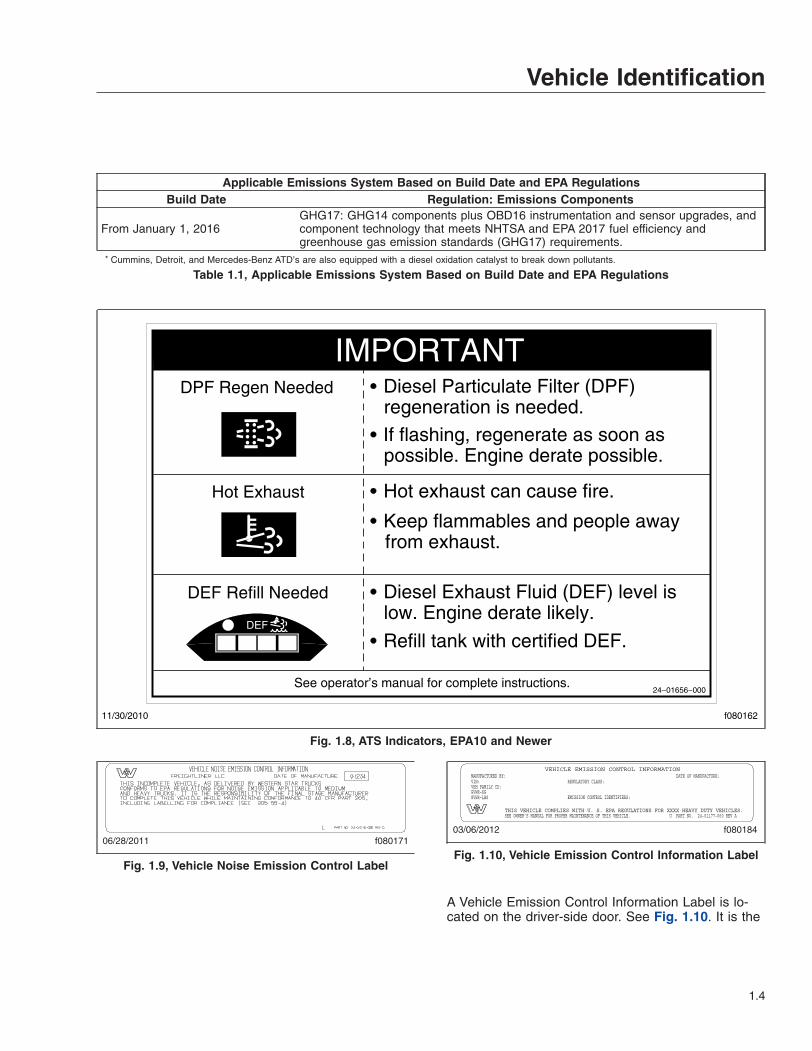
EPA Noise Emission Control LabelA vehicle noise emission control label (Fig. 1.9) islocated on the driver-side B-pillar as shown inFig. 1.2. It is the owner’s responsibility to maintainthe vehicle so that it conforms to EPA regulations.
IMPORTANT: Certain Western Star incompletevehicles may be produced with incomplete noisecontrol hardware. Such vehicles will not have avehicle noise emission control information label.For such vehicles, it is the final-stage manufac-turer’s responsibility to complete the vehicle inconformity to U.S. EPA regulations (40 CFR Part205) and label it for compliance.
Vehicle Emission Control InformationLabelModel year 2013 and later vehicles meet additionalrequirements as specified by federal greenhouse gasand fuel efficiency regulations (GHG14). Model year2017 and later vehicles meet similar requirements asspecified by GHG17 requirements. These vehiclesare equipped with components that increase fuel effi-ciency and reduce GHG emissions. Componentsmay include, but are not limited to, low rolling resis-tance tires; aerodynamic devices such as hood, cabside extenders, and fuel tank fairings; vehicle speedlimiters; and idle shutdown timers.
06/28/2011 f080175
Fig. 1.3, Vehicle Certification Label
06/28/2011 f080174
Fig. 1.4, Incomplete Vehicle Certification Label
f08002410/10/2006
Fig. 1.5, Canadian National Safety Mark
Vehicle Identification
1.2
Applicable Emissions System Based on Build Date and EPA RegulationsBuild Date Regulation: Emissions Components
January 1, 2007–December 31,2009
EPA07 (reduce nitrogen oxides (NOx) emissions to 1.1 g/bhp-hr, and reduceparticulate matter emissions to 0.01 g/bhp-hr): Aftertreatment device (ATD) containinga diesel particulate filter that traps soot and ash.*
January 1, 2010–December 31,2012
EPA10 (reduce NOx emissions to 0.2 g/bhp-hr): EPA07-type ATD, with additionalselective catalyst reduction (SCR) technology that utilizes diesel exhaust fluid (DEF)to convert NOx to nitrogen and water vapor.
From March 5, 2012–December31, 2015
GHG14: Aerodynamic and fuel efficiency components including, but not limited to,tires, cab/sleeper side extenders, chassis fairings, bumper, hood, vehicle speedlimiters, and idle reduction timers specifically designed to meet regulatory fuelefficiency and greenhouse gas emissions standards.
06/28/2011 f080172
Fig. 1.6, Component GWR Label
f080156
EXHAUST AFTERTREATMENT SYSTEM INFORMATION
Switch.
Level 1 Level 3Level 2 Level 4Filter RegenerationRecommended.
Filter is reaching
Bring vehicle tohighway speeds to
Filter Regeneration
Filter is nowreaching maximumcapacity.
To avoid enginederate, bring vehicle
Parked RegenerationRequired − EngineDerate
Filter has reachedmaximum capacity.
Vehicle must beparked, and a Parked
Service Regeneration Required.Engine Derate To Idle Only.
Filter has exceeded maximumcapacity.
Vehicle must be parked, and aService Regeneration must be
(Solid) (Flashing) (Flashing)
CHECKINDICATORLAMP(S)
Indicator LampMessage(s)
Diesel ParticulateFilter Condition
Required Action
capacity.
STOP
allow for an AutomaticRegeneration orperform a Parked
to highway speedsto allow for anAutomaticRegeneration, orperform a ParkedRegeneration assoon as possible.
Regeneration mustbe performed.Engine will beginderate.
performed. Check engineoperator’s manual for details.Engine will shut down.
For a driver performed Parked Regeneration, vehicle must be equipped with a dash mounted Regeneration Switch.
02/20/2009
WARNING
HEST (High ExhaustSystem Temperature)
Exhaust componentsand exhaust gas are athigh temperature. Whenstationary, keep awayfrom people andflammable materials orvapors.
A regeneration is inprogress.
Flashing
Solid
Regeneration.
Necessary
Fig. 1.7, ATS Indicators, EPA07
Vehicle Identification
1.3
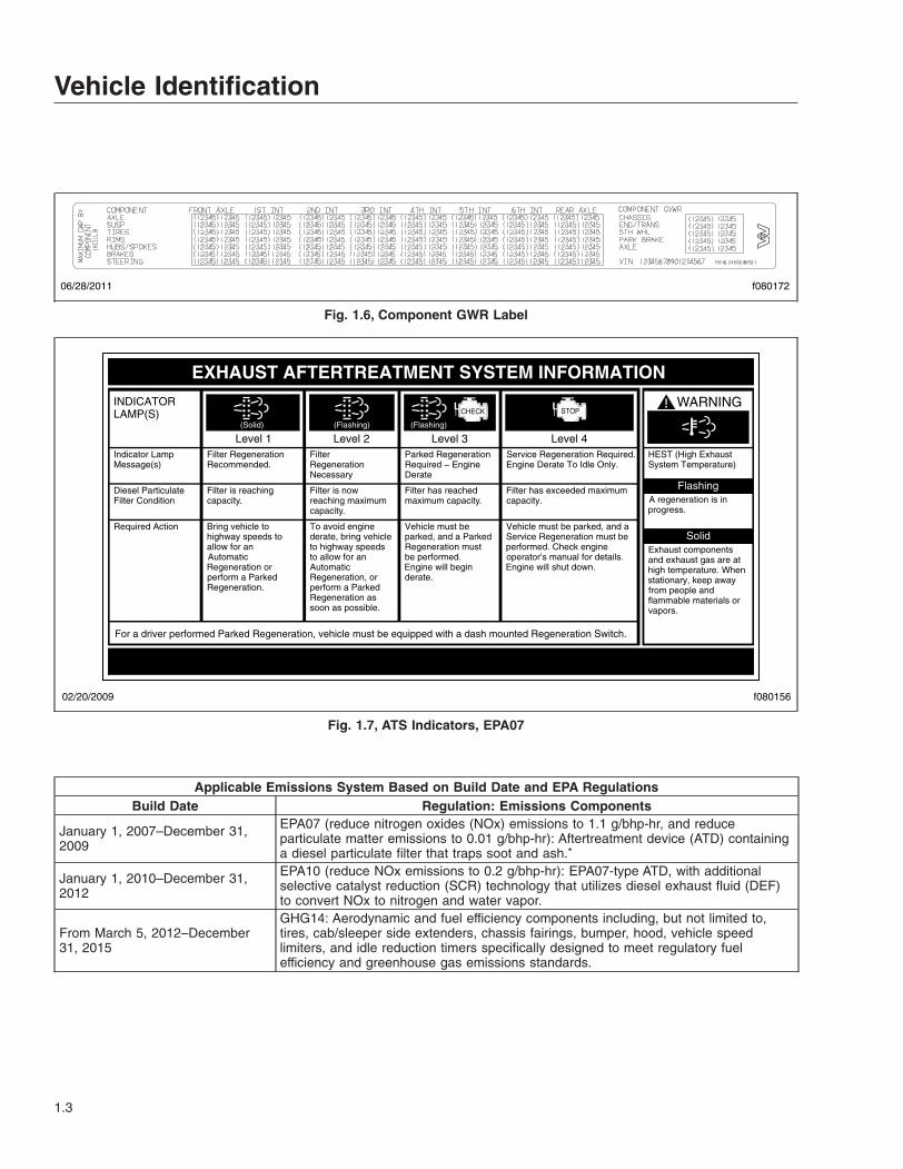
Applicable Emissions System Based on Build Date and EPA RegulationsBuild Date Regulation: Emissions Components
From January 1, 2016GHG17: GHG14 components plus OBD16 instrumentation and sensor upgrades, andcomponent technology that meets NHTSA and EPA 2017 fuel efficiency andgreenhouse gas emission standards (GHG17) requirements.
* Cummins, Detroit, and Mercedes-Benz ATD’s are also equipped with a diesel oxidation catalyst to break down pollutants.
Table 1.1, Applicable Emissions System Based on Build Date and EPA Regulations
A Vehicle Emission Control Information Label is lo-cated on the driver-side door. See Fig. 1.10. It is the
DPF Regen Needed
Hot Exhaust
DEF Refill Needed
Diesel Particulate Filter (DPF)regeneration is needed.
If flashing, regenerate as soon aspossible. Engine derate possible.
Hot exhaust can cause fire.
Keep flammables and people awayfrom exhaust.
Diesel Exhaust Fluid (DEF) level islow. Engine derate likely.
Refill tank with certified DEF.
24−01656−000
IMPORTANT
DEF
11/30/2010 f080162
See operator’s manual for complete instructions.
Fig. 1.8, ATS Indicators, EPA10 and Newer
06/28/2011 f080171
Fig. 1.9, Vehicle Noise Emission Control Label
f08018403/06/2012
MANUFACTURED BY:VIN:VEH FAMILY CD:GVWR−KGGVWR−LBS
REGULATORY CLASS:
EMISSION CONTROL IDENTIFIERS:
DATE OF MANUFACTURE:VEHICLE EMISSION CONTROL INFORMATION
THIS VEHICLE COMPLIES WITH U. S. EPA REGULATIONS FOR XXXX HEAVY DUTY VEHICLES.SEE OWNER’S MANUAL FOR PROPER MAINTENANCE OF THIS VEHICLE. U PART NO. 24−01177−060 REV A
Fig. 1.10, Vehicle Emission Control Information Label
Vehicle Identification
1.4

owner’s responsibility to maintain the vehicle so thatit conforms to EPA and NHTSA regulations.
Certified Clean Idle LabelThe California Air Resources Board (CARB) requiresmodel year 2008 and newer heavy-duty diesel en-gines to be equipped with a non-programmable en-gine shutdown system that automatically shuts downthe engine after five minutes of idling in order to limitemissions of particulate matter and NOx.
Certified vehicles are equipped with a label placednear the bottom edge of the driver-side door. SeeFig. 1.11.
CERTIFIEDCLEAN IDLE
02/20/2012 f080179
Fig. 1.11, CARB Clean Idle Label
Vehicle Identification
1.5
2
Vehicle AccessDoor Locks and Handles . . . . . . . . . . . . . . . . . . . . . . . . . . . . . . . . . . . . . . . . . . . . . . . . . . . . . . . . . . . 2.1Grab Handles and Access Steps . . . . . . . . . . . . . . . . . . . . . . . . . . . . . . . . . . . . . . . . . . . . . . . . . . . . . 2.2Back-of-Cab Access . . . . . . . . . . . . . . . . . . . . . . . . . . . . . . . . . . . . . . . . . . . . . . . . . . . . . . . . . . . . . . . 2.5Hood Opening and Closing . . . . . . . . . . . . . . . . . . . . . . . . . . . . . . . . . . . . . . . . . . . . . . . . . . . . . . . . . 2.7
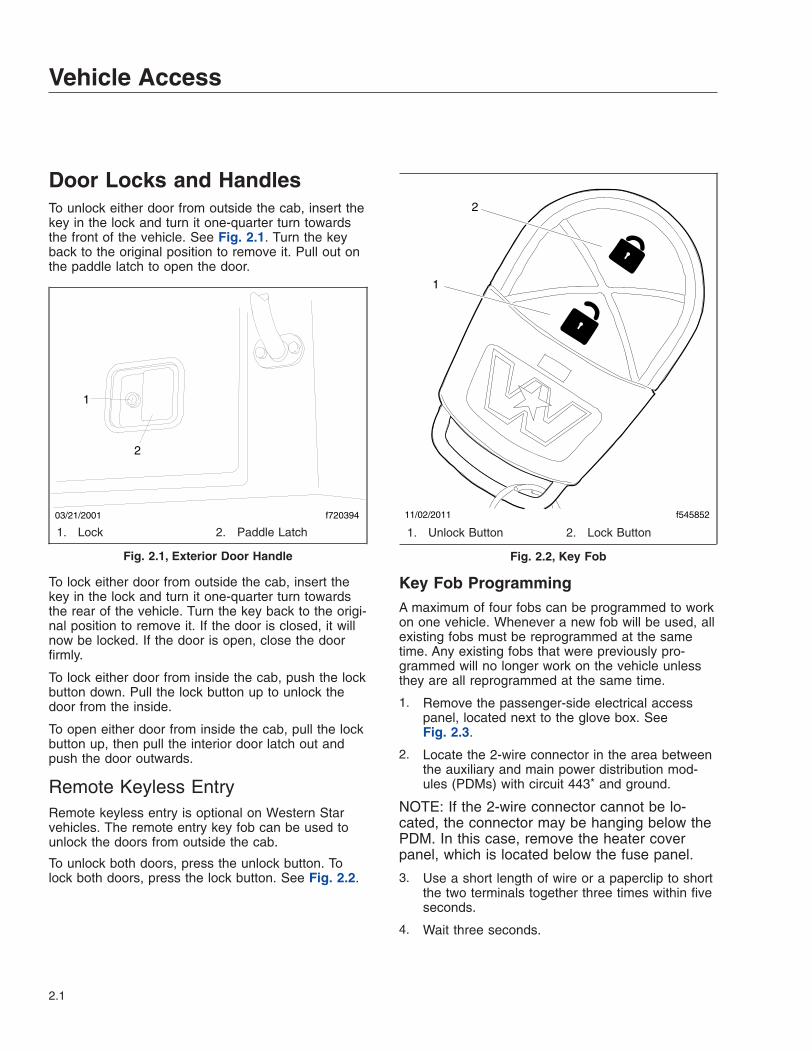
Door Locks and HandlesTo unlock either door from outside the cab, insert thekey in the lock and turn it one-quarter turn towardsthe front of the vehicle. See Fig. 2.1. Turn the keyback to the original position to remove it. Pull out onthe paddle latch to open the door.
To lock either door from outside the cab, insert thekey in the lock and turn it one-quarter turn towardsthe rear of the vehicle. Turn the key back to the origi-nal position to remove it. If the door is closed, it willnow be locked. If the door is open, close the doorfirmly.
To lock either door from inside the cab, push the lockbutton down. Pull the lock button up to unlock thedoor from the inside.
To open either door from inside the cab, pull the lockbutton up, then pull the interior door latch out andpush the door outwards.
Remote Keyless EntryRemote keyless entry is optional on Western Starvehicles. The remote entry key fob can be used tounlock the doors from outside the cab.
To unlock both doors, press the unlock button. Tolock both doors, press the lock button. See Fig. 2.2.
Key Fob ProgrammingA maximum of four fobs can be programmed to workon one vehicle. Whenever a new fob will be used, allexisting fobs must be reprogrammed at the sametime. Any existing fobs that were previously pro-grammed will no longer work on the vehicle unlessthey are all reprogrammed at the same time.
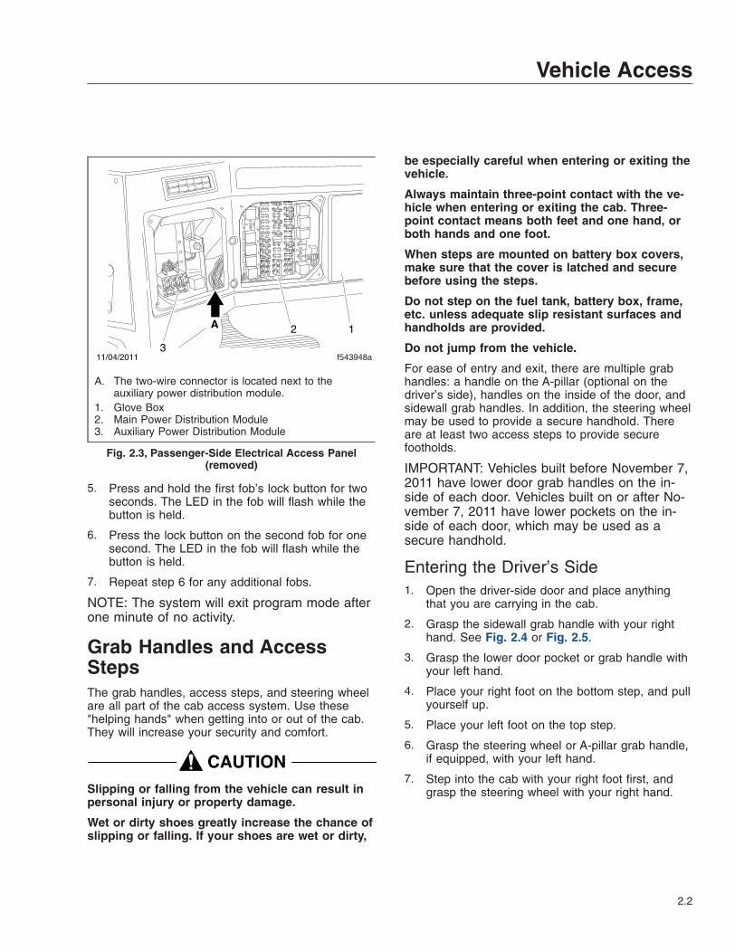
1. Remove the passenger-side electrical accesspanel, located next to the glove box. SeeFig. 2.3.
2. Locate the 2-wire connector in the area betweenthe auxiliary and main power distribution mod-ules (PDMs) with circuit 443* and ground.
NOTE: If the 2-wire connector cannot be lo-cated, the connector may be hanging below thePDM. In this case, remove the heater coverpanel, which is located below the fuse panel.
3. Use a short length of wire or a paperclip to shortthe two terminals together three times within fiveseconds.
4. Wait three seconds.
03/21/2001 f720394
1
2
1. Lock 2. Paddle Latch
Fig. 2.1, Exterior Door Handle
11/02/2011 f545852
1
2
1. Unlock Button 2. Lock Button
Fig. 2.2, Key Fob
Vehicle Access
2.1
5. Press and hold the first fob’s lock button for twoseconds. The LED in the fob will flash while thebutton is held.
6. Press the lock button on the second fob for onesecond. The LED in the fob will flash while thebutton is held.
7. Repeat step 6 for any additional fobs.
NOTE: The system will exit program mode afterone minute of no activity.
Grab Handles and AccessStepsThe grab handles, access steps, and steering wheelare all part of the cab access system. Use these"helping hands" when getting into or out of the cab.They will increase your security and comfort.
CAUTIONSlipping or falling from the vehicle can result inpersonal injury or property damage.
Wet or dirty shoes greatly increase the chance ofslipping or falling. If your shoes are wet or dirty,
be especially careful when entering or exiting thevehicle.
Always maintain three-point contact with the ve-hicle when entering or exiting the cab. Three-point contact means both feet and one hand, orboth hands and one foot.
When steps are mounted on battery box covers,make sure that the cover is latched and securebefore using the steps.
Do not step on the fuel tank, battery box, frame,etc. unless adequate slip resistant surfaces andhandholds are provided.
Do not jump from the vehicle.
For ease of entry and exit, there are multiple grabhandles: a handle on the A-pillar (optional on thedriver’s side), handles on the inside of the door, andsidewall grab handles. In addition, the steering wheelmay be used to provide a secure handhold. Thereare at least two access steps to provide securefootholds.
IMPORTANT: Vehicles built before November 7,2011 have lower door grab handles on the in-side of each door. Vehicles built on or after No-vember 7, 2011 have lower pockets on the in-side of each door, which may be used as asecure handhold.
Entering the Driver’s Side1. Open the driver-side door and place anything
that you are carrying in the cab.
2. Grasp the sidewall grab handle with your righthand. See Fig. 2.4 or Fig. 2.5.
3. Grasp the lower door pocket or grab handle withyour left hand.
4. Place your right foot on the bottom step, and pullyourself up.
5. Place your left foot on the top step.
6. Grasp the steering wheel or A-pillar grab handle,if equipped, with your left hand.
7. Step into the cab with your right foot first, andgrasp the steering wheel with your right hand.
f543948a
12
311/04/2011
A
A. The two-wire connector is located next to theauxiliary power distribution module.
1. Glove Box2. Main Power Distribution Module3. Auxiliary Power Distribution Module
Fig. 2.3, Passenger-Side Electrical Access Panel(removed)
Vehicle Access
2.2
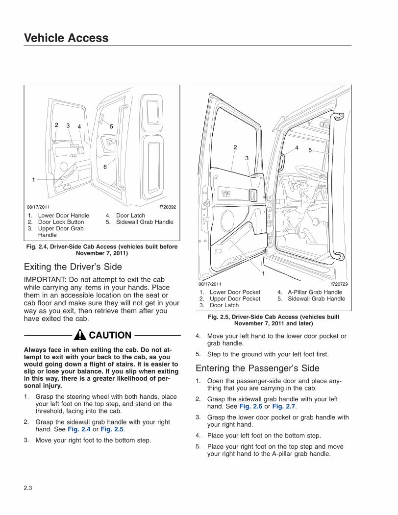
Exiting the Driver’s SideIMPORTANT: Do not attempt to exit the cabwhile carrying any items in your hands. Placethem in an accessible location on the seat orcab floor and make sure they will not get in yourway as you exit, then retrieve them after youhave exited the cab.
CAUTIONAlways face in when exiting the cab. Do not at-tempt to exit with your back to the cab, as youwould going down a flight of stairs. It is easier toslip or lose your balance. If you slip when exitingin this way, there is a greater likelihood of per-sonal injury.
1. Grasp the steering wheel with both hands, placeyour left foot on the top step, and stand on thethreshold, facing into the cab.
2. Grasp the sidewall grab handle with your righthand. See Fig. 2.4 or Fig. 2.5.
3. Move your right foot to the bottom step.
4. Move your left hand to the lower door pocket orgrab handle.
5. Step to the ground with your left foot first.
Entering the Passenger’s Side1. Open the passenger-side door and place any-
thing that you are carrying in the cab.
2. Grasp the sidewall grab handle with your lefthand. See Fig. 2.6 or Fig. 2.7.
3. Grasp the lower door pocket or grab handle withyour right hand.
4. Place your left foot on the bottom step.
5. Place your right foot on the top step and moveyour right hand to the A-pillar grab handle.
1
6
2 3 4
f72039208/17/2011
5
1. Lower Door Handle2. Door Lock Button3. Upper Door Grab
Handle
4. Door Latch5. Sidewall Grab Handle
Fig. 2.4, Driver-Side Cab Access (vehicles built beforeNovember 7, 2011)
08/17/2011 f720729
1
2
3
4 5
1. Lower Door Pocket2. Upper Door Pocket3. Door Latch
4. A-Pillar Grab Handle5. Sidewall Grab Handle
Fig. 2.5, Driver-Side Cab Access (vehicles builtNovember 7, 2011 and later)
Vehicle Access
2.3
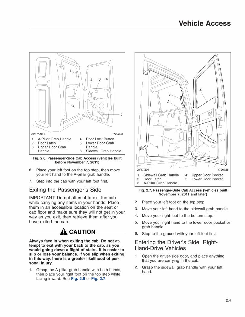
6. Place your left foot on the top step, then moveyour left hand to the A-pillar grab handle.
7. Step into the cab with your left foot first.
Exiting the Passenger’s SideIMPORTANT: Do not attempt to exit the cabwhile carrying any items in your hands. Placethem in an accessible location on the seat orcab floor and make sure they will not get in yourway as you exit, then retrieve them after youhave exited the cab.
CAUTIONAlways face in when exiting the cab. Do not at-tempt to exit with your back to the cab, as youwould going down a flight of stairs. It is easier toslip or lose your balance. If you slip when exitingin this way, there is a greater likelihood of per-sonal injury.
1. Grasp the A-pillar grab handle with both hands,then place your right foot on the top step whilefacing inward. See Fig. 2.6 or Fig. 2.7.
2. Place your left foot on the top step.
3. Move your left hand to the sidewall grab handle.
4. Move your right foot to the bottom step.
5. Move your right hand to the lower door pocket orgrab handle.
6. Step to the ground with your left foot first.
Entering the Driver’s Side, Right-Hand-Drive Vehicles1. Open the driver-side door, and place anything
that you are carrying in the cab.
2. Grasp the sidewall grab handle with your lefthand.
1
2 3 4
5
f72039308/17/2011
6
1. A-Pillar Grab Handle2. Door Latch3. Upper Door Grab
Handle
4. Door Lock Button5. Lower Door Grab
Handle6. Sidewall Grab Handle
Fig. 2.6, Passenger-Side Cab Access (vehicles builtbefore November 7, 2011)
08/17/2011 f7207285
1
2
34
1. Sidewall Grab Handle2. Door Latch3. A-Pillar Grab Handle
4. Upper Door Pocket5. Lower Door Pocket
Fig. 2.7, Passenger-Side Cab Access (vehicles builtNovember 7, 2011 and later)
Vehicle Access
2.4
3. Grasp the lower door pocket or grab handle withyour right hand.
4. Place your left foot on the bottom step.
5. Place your right foot on the top step.
6. Move your right hand to the steering wheel orA-pillar grab handle, if equipped.
7. Step into the cab with your left foot first, andgrasp the steering wheel with your left hand.
Exiting the Driver’s Side, Right-Hand-Drive VehiclesIMPORTANT: Do not attempt to exit the cabwhile carrying any items in your hands. Placethem in an accessible location on the seat orcab floor and make sure they will not get in yourway as you exit, then retrieve them after youhave exited the cab.
CAUTIONAlways face in when exiting the cab. Do not at-tempt to exit with your back to the cab, as youwould going down a flight of stairs. It is easier toslip or lose your balance. If you slip when exitingin this way, there is a greater likelihood of per-sonal injury.
1. Grasp the steering wheel with both hands, placeyour right foot on the top step, and stand on thethreshold, facing into the cab.
2. Grasp the sidewall grab handle with your lefthand.
3. Move your left foot to the bottom step.
4. Move your right hand to the lower door pocket orgrab handle.
5. Step to the ground with your right foot first.
Entering the Passenger’s Side, Right-Hand-Drive Vehicles1. Open the passenger-side door and place any-
thing that you are carrying in the cab.
2. Grasp the sidewall grab handle with your righthand.
3. Grasp the lower door pocket or grab handle withyour left hand.
4. Place your right foot on the bottom step.
5. Place your left foot on the top step and moveyour left hand to the A-pillar grab handle.
6. Place your right foot on the top step, then moveyour right hand to the A-pillar grab handle.
7. Step into the cab with your right foot first.
Exiting the Passenger’s Side, Right-Hand-Drive VehiclesIMPORTANT: Do not attempt to exit the cabwhile carrying any items in your hands. Placethem in an accessible location on the seat orcab floor and make sure they will not get in yourway as you exit, then retrieve them after youhave exited the cab.
CAUTIONAlways face in when exiting the cab. Do not at-tempt to exit with your back to the cab, as youwould going down a flight of stairs. It is easier toslip or lose your balance. If you slip when exitingin this way, there is a greater likelihood of per-sonal injury.
1. Grasp the A-pillar grab handle with both hands,then place your left foot on the top step whilestanding up from the seat facing inward.
2. Place your right foot on the top step.
3. Move your right hand to the sidewall grabhandle.
4. Move your right foot to the bottom step.
5. Move your left hand to the lower door pocket orgrab handle.
6. Step to the ground with your left foot first.
Back-of-Cab AccessWhen trailer air and electrical connections cannot bereached conveniently from the ground, Federal MotorCarrier Safety Regulations require that tractors haveadequate back-of-cab access. Grab handles are typi-cally located on the backwall of the cab or sleeper, oron the inside of the cab extender, if equipped. See
Vehicle Access
2.5
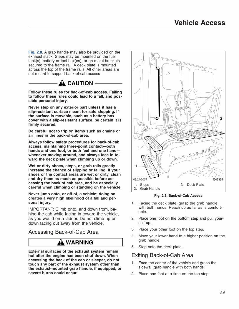
Fig. 2.8. A grab handle may also be provided on theexhaust stack. Steps may be mounted on the fueltank(s), battery or tool box(es), or on metal bracketssecured to the frame rail. A deck plate is mountedacross the top of the frame rails. All other areas arenot meant to support back-of-cab access
CAUTIONFollow these rules for back-of-cab access. Failingto follow these rules could lead to a fall, and pos-sible personal injury.
Never step on any exterior part unless it has aslip-resistant surface meant for safe stepping. Ifthe surface is movable, such as a battery boxcover with a slip-resistant surface, be certain it isfirmly secured.
Be careful not to trip on items such as chains orair lines in the back-of-cab area.
Always follow safety procedures for back-of-cabaccess, maintaining three-point contact—bothhands and one foot, or both feet and one hand—whenever moving around, and always face in to-ward the deck plate when climbing up or down.
Wet or dirty shoes, steps, or grab rails greatlyincrease the chance of slipping or falling. If yourshoes or the contact areas are wet or dirty, cleanand dry them as much as possible before ac-cessing the back of cab area, and be especiallycareful when climbing or standing on the vehicle.
Never jump onto, or off of, a vehicle; doing socreates a very high likelihood of a fall and per-sonal injury.
IMPORTANT: Climb onto, and down from, be-hind the cab while facing in toward the vehicle,as you would on a ladder. Do not climb up ordown facing out away from the vehicle.
Accessing Back-of-Cab Area
WARNINGExternal surfaces of the exhaust system remainhot after the engine has been shut down. Whenaccessing the back of the cab or sleeper, do nottouch any part of the exhaust system other thanthe exhaust-mounted grab handle, if equipped, orsevere burns could occur.
1. Facing the deck plate, grasp the grab handlewith both hands. Reach up as far as is comfort-able.
2. Place one foot on the bottom step and pull your-self up.
3. Place your other foot on the top step.
4. Move your lower hand to a higher position on thegrab handle.
5. Step onto the deck plate.
Exiting Back-of-Cab Area1. Face the center of the vehicle and grasp the
sidewall grab handle with both hands.
2. Place one foot at a time on the top step.
09/24/2007 f602335
2
1
1
3
1. Steps2. Grab Handle
3. Deck Plate
Fig. 2.8, Back-of-Cab Access
Vehicle Access
2.6
3. Move your upper hand to a lower position on thegrab handle.
4. Move one foot to the bottom step.
5. Step to the ground with your upper foot first.
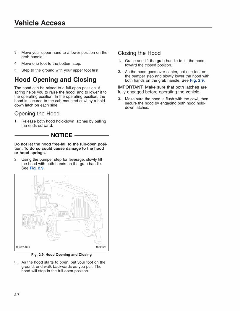
Hood Opening and ClosingThe hood can be raised to a full-open position. Aspring helps you to raise the hood, and to lower it tothe operating position. In the operating position, thehood is secured to the cab-mounted cowl by a hold-down latch on each side.
Opening the Hood1. Release both hood hold-down latches by pulling
the ends outward.
NOTICEDo not let the hood free-fall to the full-open posi-tion. To do so could cause damage to the hoodor hood springs.
2. Using the bumper step for leverage, slowly tiltthe hood with both hands on the grab handle.See Fig. 2.9.
3. As the hood starts to open, put your foot on theground, and walk backwards as you pull. Thehood will stop in the full-open position.
Closing the Hood1. Grasp and lift the grab handle to tilt the hood
toward the closed position.
2. As the hood goes over center, put one foot onthe bumper step and slowly lower the hood withboth hands on the grab handle. See Fig. 2.9.
IMPORTANT: Make sure that both latches arefully engaged before operating the vehicle.
3. Make sure the hood is flush with the cowl, thensecure the hood by engaging both hood hold-down latches.
03/22/2001 f880526
Fig. 2.9, Hood Opening and Closing
Vehicle Access
2.7
3
InstrumentsWarning and Indicator Lights . . . . . . . . . . . . . . . . . . . . . . . . . . . . . . . . . . . . . . . . . . . . . . . . . . . . . . . . 3.1Standard Instruments . . . . . . . . . . . . . . . . . . . . . . . . . . . . . . . . . . . . . . . . . . . . . . . . . . . . . . . . . . . . . . 3.3Optional Instruments . . . . . . . . . . . . . . . . . . . . . . . . . . . . . . . . . . . . . . . . . . . . . . . . . . . . . . . . . . . . . . 3.6Overhead Instrument Panel, Optional . . . . . . . . . . . . . . . . . . . . . . . . . . . . . . . . . . . . . . . . . . . . . . . . . 3.8
Warning and Indicator LightsVehicles built since January 1, 2007 are equippedwith a located behind the steering wheel, and con-tains all standard and optional warning and indicatorlamps, or telltales.
See Table 3.1 for a listing of standard and commonlyused optional telltales.
The following fixed-position lamps are standard:
• left-turn signal
• high-beam headlights
• daytime running lights
• right-turn signal
• low air pressure
• wait to start (EPA10 and newer vehicles)
• high exhaust system temperature (HEST)
• diesel particulate filter (DPF) status
• malfunction indicator lamp (MIL)
• CHECK engine
• STOP engine
• trailer antilock braking system (ABS)
• tractor ABS
• parking brake engaged
The following lamps are optional:
• rear suspension air pressure
• check transmission
• transmission temperature
• service transmission
• wheel spin
• unfastened seat belt
• intake heater
• water in fuel
• fuel filter restriction
• optimized idle
• power takeoff (PTO) engaged
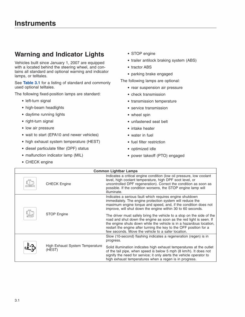
Common Lightbar Lamps
CHECK Engine
Indicates a critical engine condition (low oil pressure, low coolantlevel, high coolant temperature, high DPF soot level, oruncontrolled DPF regeneration). Correct the condition as soon aspossible. If the condition worsens, the STOP engine lamp willilluminate.
STOP Engine
Indicates a serious fault which requires engine shutdownimmediately. The engine protection system will reduce themaximum engine torque and speed, and, if the condition does notimprove, will shut down the engine within 30 to 60 seconds.
The driver must safely bring the vehicle to a stop on the side of theroad and shut down the engine as soon as the red light is seen. Ifthe engine shuts down while the vehicle is in a hazardous location,restart the engine after turning the key to the OFF position for afew seconds. Move the vehicle to a safer location.
High Exhaust System Temperature(HEST)
Slow (10-second) flashing indicates a regeneration (regen) is inprogress.
Solid illumination indicates high exhaust temperatures at the outletof the tail pipe, when speed is below 5 mph (8 km/h). It does notsignify the need for service; it only alerts the vehicle operator tohigh exhaust temperatures when a regen is in progress.
Instruments
3.1
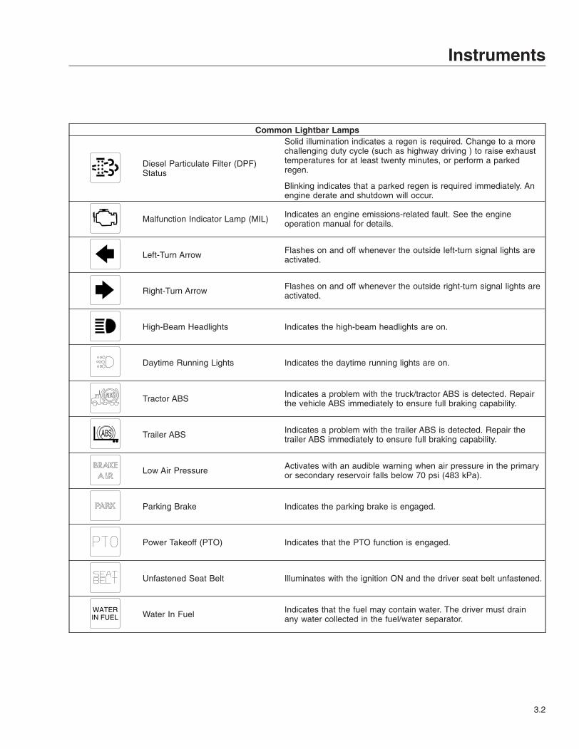
Common Lightbar Lamps
Diesel Particulate Filter (DPF)Status
Solid illumination indicates a regen is required. Change to a morechallenging duty cycle (such as highway driving ) to raise exhausttemperatures for at least twenty minutes, or perform a parkedregen.
Blinking indicates that a parked regen is required immediately. Anengine derate and shutdown will occur.
Malfunction Indicator Lamp (MIL) Indicates an engine emissions-related fault. See the engineoperation manual for details.
Left-Turn Arrow Flashes on and off whenever the outside left-turn signal lights areactivated.
Right-Turn Arrow Flashes on and off whenever the outside right-turn signal lights areactivated.
High-Beam Headlights Indicates the high-beam headlights are on.
Daytime Running Lights Indicates the daytime running lights are on.
Tractor ABS Indicates a problem with the truck/tractor ABS is detected. Repairthe vehicle ABS immediately to ensure full braking capability.
Trailer ABS Indicates a problem with the trailer ABS is detected. Repair thetrailer ABS immediately to ensure full braking capability.
Low Air Pressure Activates with an audible warning when air pressure in the primaryor secondary reservoir falls below 70 psi (483 kPa).
Parking Brake Indicates the parking brake is engaged.
Power Takeoff (PTO) Indicates that the PTO function is engaged.
Unfastened Seat Belt Illuminates with the ignition ON and the driver seat belt unfastened.
WATERIN FUEL Water In Fuel Indicates that the fuel may contain water. The driver must drain
any water collected in the fuel/water separator.
Instruments
3.2
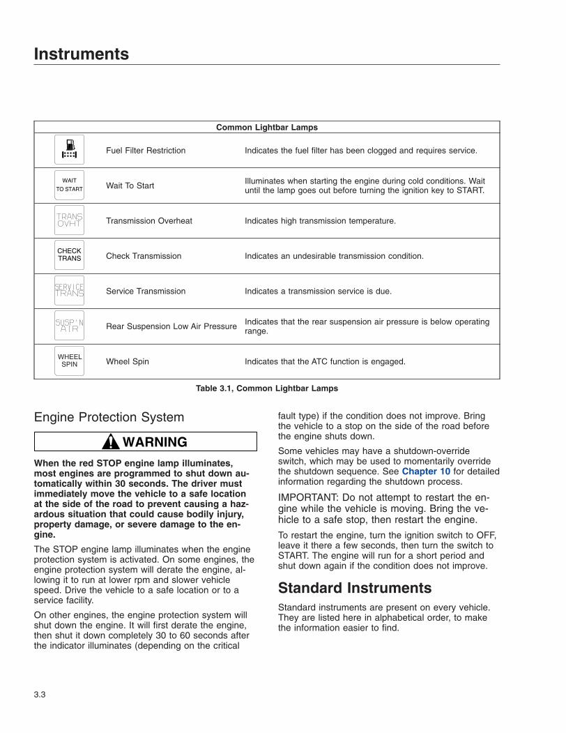
Common Lightbar Lamps
Fuel Filter Restriction Indicates the fuel filter has been clogged and requires service.
WAIT
TO START Wait To Start Illuminates when starting the engine during cold conditions. Waituntil the lamp goes out before turning the ignition key to START.
Transmission Overheat Indicates high transmission temperature.
CHECKTRANS Check Transmission Indicates an undesirable transmission condition.
Service Transmission Indicates a transmission service is due.
Rear Suspension Low Air Pressure Indicates that the rear suspension air pressure is below operatingrange.
WHEELSPIN Wheel Spin Indicates that the ATC function is engaged.
Table 3.1, Common Lightbar Lamps
Engine Protection System
WARNINGWhen the red STOP engine lamp illuminates,most engines are programmed to shut down au-tomatically within 30 seconds. The driver mustimmediately move the vehicle to a safe locationat the side of the road to prevent causing a haz-ardous situation that could cause bodily injury,property damage, or severe damage to the en-gine.
The STOP engine lamp illuminates when the engineprotection system is activated. On some engines, theengine protection system will derate the engine, al-lowing it to run at lower rpm and slower vehiclespeed. Drive the vehicle to a safe location or to aservice facility.
On other engines, the engine protection system willshut down the engine. It will first derate the engine,then shut it down completely 30 to 60 seconds afterthe indicator illuminates (depending on the critical
fault type) if the condition does not improve. Bringthe vehicle to a stop on the side of the road beforethe engine shuts down.
Some vehicles may have a shutdown-overrideswitch, which may be used to momentarily overridethe shutdown sequence. See Chapter 10 for detailedinformation regarding the shutdown process.
IMPORTANT: Do not attempt to restart the en-gine while the vehicle is moving. Bring the ve-hicle to a safe stop, then restart the engine.
To restart the engine, turn the ignition switch to OFF,leave it there a few seconds, then turn the switch toSTART. The engine will run for a short period andshut down again if the condition does not improve.
Standard InstrumentsStandard instruments are present on every vehicle.They are listed here in alphabetical order, to makethe information easier to find.
Instruments
3.3
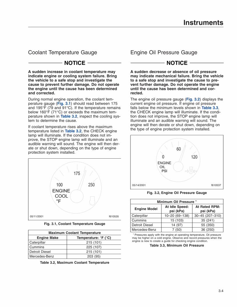
Coolant Temperature Gauge
NOTICEA sudden increase in coolant temperature mayindicate engine or cooling system failure. Bringthe vehicle to a safe stop and investigate thecause to prevent further damage. Do not operatethe engine until the cause has been determinedand corrected.
During normal engine operation, the coolant tem-perature gauge (Fig. 3.1) should read between 175and 195°F (79 and 91°C). If the temperature remainsbelow 160°F (71°C) or exceeds the maximum tem-perature shown in Table 3.2, inspect the cooling sys-tem to determine the cause.
If coolant temperature rises above the maximumtemperature listed in Table 3.2, the CHECK enginelamp will illuminate. If the condition does not im-prove, the STOP engine lamp will illuminate and anaudible warning will sound. The engine will then der-ate or shut down, depending on the type of engineprotection system installed.
Maximum Coolant TemperatureEngine Make Temperature: °F (°C)
Caterpillar 215 (101)Cummins 225 (107)Detroit Diesel 215 (101)Mercedes-Benz 203 (95)
Table 3.2, Maximum Coolant Temperature
Engine Oil Pressure Gauge
NOTICEA sudden decrease or absence of oil pressuremay indicate mechanical failure. Bring the vehicleto a safe stop and investigate the cause to pre-vent further damage. Do not operate the engineuntil the cause has been determined and cor-rected.
The engine oil pressure gauge (Fig. 3.2) displays thecurrent engine oil pressure. If engine oil pressurefalls below the minimum levels shown in Table 3.3,the CHECK engine lamp will illuminate. If the condi-tion does not improve, the STOP engine lamp willilluminate and an audible warning will sound. Theengine will then derate or shut down, depending onthe type of engine protection system installed.
Minimum Oil Pressure *
Engine ModelAt Idle Speed:
psi (kPa)At Rated RPM:
psi (kPa)Caterpillar 10–20 (69–138) 30–45 (207–310)Cummins 15 (103) 35 (241)Detroit Diesel 14 (97) 55 (350)Mercedes-Benz 7 (50) 36 (250)* Pressures apply with the engine at operating temperature. Oil pressure
may be higher on a cold engine. Observe and record pressures when theengine is new to create a guide for checking engine condition.
Table 3.3, Minimum Oil Pressure
05/11/2001 f610535
Fig. 3.1, Coolant Temperature Gauge
05/14/2001 f610537
Fig. 3.2, Engine Oil Pressure Gauge
Instruments
3.4
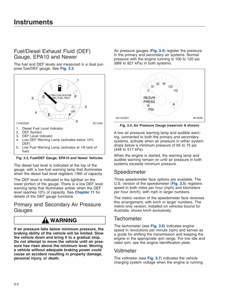
Fuel/Diesel Exhaust Fluid (DEF)Gauge, EPA10 and NewerThe fuel and DEF levels are measured in a dual pur-pose fuel/DEF gauge. See Fig. 3.3.
The diesel fuel level is indicated at the top of thegauge, with a low-fuel warning lamp that illuminateswhen the diesel fuel level registers 1/8th of capacity.
The DEF level is indicated in the lightbar on thelower portion of the gauge. There is a low DEF levelwarning lamp that illuminates amber when the DEFlevel reaches 10% of capacity. See Chapter 11 fordetails of the DEF gauge functions.
Primary and Secondary Air PressureGauges
WARNINGIf air pressure falls below minimum pressure, thebraking ability of the vehicle will be limited. Slowthe vehicle down and bring it to a gradual stop.Do not attempt to move the vehicle until air pres-sure has risen above the minimum level. Movinga vehicle without adequate braking power couldcause an accident resulting in property damage,personal injury, or death.
Air pressure gauges (Fig. 3.4) register the pressurein the primary and secondary air systems. Normalpressure with the engine running is 100 to 120 psi(689 to 827 kPa) in both systems.
A low air pressure warning lamp and audible warn-ing, connected to both the primary and secondarysystems, activate when air pressure in either systemdrops below a minimum pressure of 65 to 75 psi(448 to 517 kPa).
When the engine is started, the warning lamp andaudible warning remain on until air pressure in bothsystems exceeds minimum pressure.
SpeedometerThree speedometer face options are available. TheU.S. version of the speedometer (Fig. 3.5) registersspeed in both miles per hour (mph) and kilometersper hour (km/h), with mph in larger numbers.
The metric version of the speedometer face reversesthis arrangement, with km/h in larger numbers. Themetric-only version, installed on vehicles bound forAustralia, shows km/h exclusively.
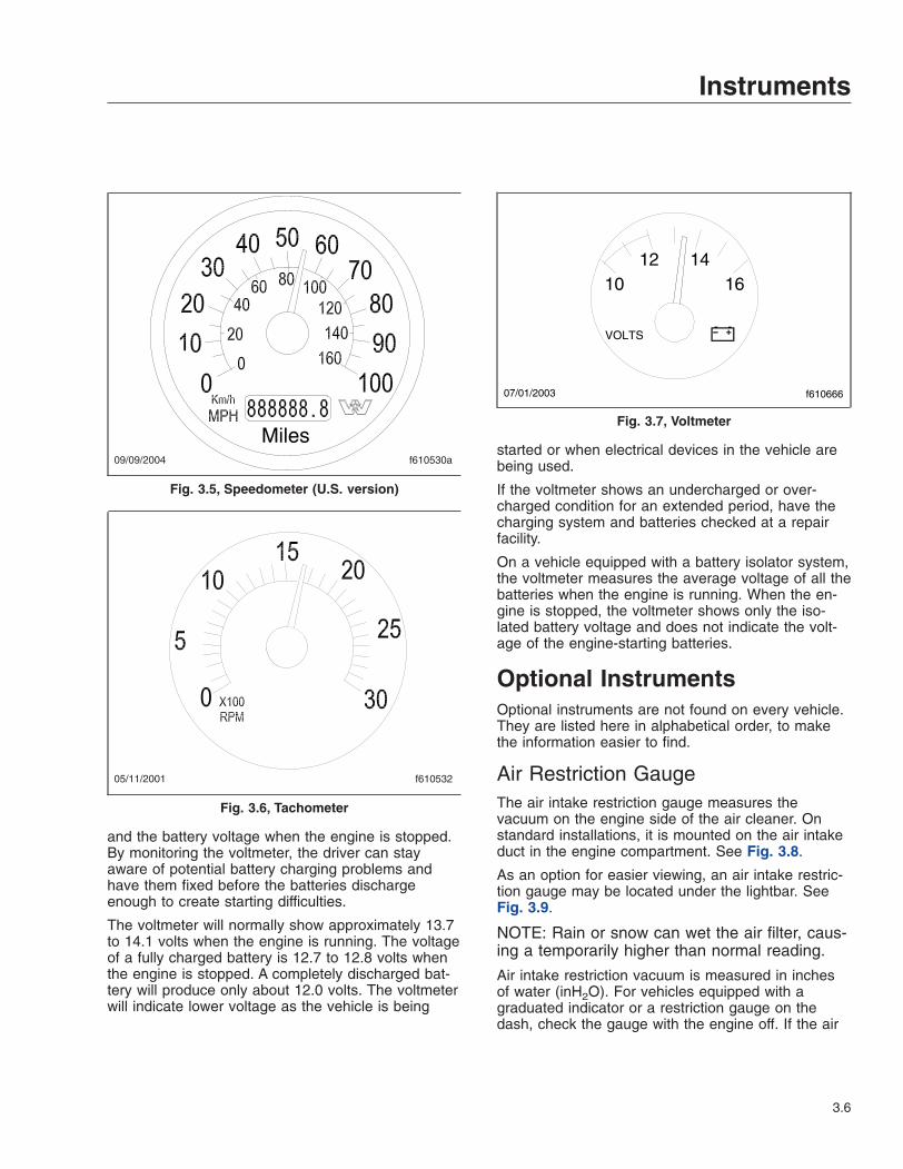
TachometerThe tachometer (see Fig. 3.6) indicates enginespeed in revolutions per minute (rpm) and serves asa guide for shifting the transmission and keeping theengine in the appropriate rpm range. For low idle andrated rpm, see the engine identification plate.
VoltmeterThe voltmeter (see Fig. 3.7) indicates the vehiclecharging system voltage when the engine is running
11/09/2009 f611046
1
2
3
4
5
1. Diesel Fuel Level Indicator2. DEF Symbol3. DEF Level Indicator4. Low DEF Warning Lamp (activates below 10%
DEF)5. Low Fuel Warning Lamp (activates at 1/8 tank of
fuel)
Fig. 3.3, Fuel/DEF Gauge, EPA10 and Newer Vehicles
05/14/2001 f610556
Fig. 3.4, Air Pressure Gauge (reservoir A shown)
Instruments
3.5
and the battery voltage when the engine is stopped.By monitoring the voltmeter, the driver can stayaware of potential battery charging problems andhave them fixed before the batteries dischargeenough to create starting difficulties.
The voltmeter will normally show approximately 13.7to 14.1 volts when the engine is running. The voltageof a fully charged battery is 12.7 to 12.8 volts whenthe engine is stopped. A completely discharged bat-tery will produce only about 12.0 volts. The voltmeterwill indicate lower voltage as the vehicle is being
started or when electrical devices in the vehicle arebeing used.
If the voltmeter shows an undercharged or over-charged condition for an extended period, have thecharging system and batteries checked at a repairfacility.
On a vehicle equipped with a battery isolator system,the voltmeter measures the average voltage of all thebatteries when the engine is running. When the en-gine is stopped, the voltmeter shows only the iso-lated battery voltage and does not indicate the volt-age of the engine-starting batteries.
Optional InstrumentsOptional instruments are not found on every vehicle.They are listed here in alphabetical order, to makethe information easier to find.
Air Restriction GaugeThe air intake restriction gauge measures thevacuum on the engine side of the air cleaner. Onstandard installations, it is mounted on the air intakeduct in the engine compartment. See Fig. 3.8.
As an option for easier viewing, an air intake restric-tion gauge may be located under the lightbar. SeeFig. 3.9.
NOTE: Rain or snow can wet the air filter, caus-ing a temporarily higher than normal reading.
Air intake restriction vacuum is measured in inchesof water (inH2O). For vehicles equipped with agraduated indicator or a restriction gauge on thedash, check the gauge with the engine off. If the air
09/09/2004 f610530a
Miles
Fig. 3.5, Speedometer (U.S. version)
05/11/2001 f610532
Fig. 3.6, Tachometer
07/01/2003 f610666
1012 14
16
VOLTS
Fig. 3.7, Voltmeter
Instruments
3.6
restriction value equals or exceeds the value shownin Table 3.4, the air cleaner element needs to bereplaced.
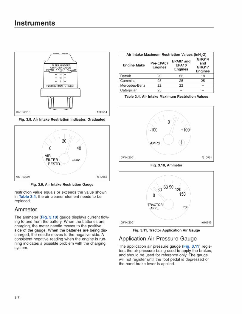
AmmeterThe ammeter (Fig. 3.10) gauge displays current flow-ing to and from the battery. When the batteries arecharging, the meter needle moves to the positiveside of the gauge. When the batteries are being dis-charged, the needle moves to the negative side. Aconsistent negative reading when the engine is run-ning indicates a possible problem with the chargingsystem.
Air Intake Maximum Restriction Values (inH2O)
Engine Make Pre-EPA07Engines
EPA07 andEPA10
Engines
GHG14and
GHG17Engines
Detroit 20 22 18Cummins 25 25 25Mercedes-Benz 22 22 –Caterpillar 25 – –
Table 3.4, Air Intake Maximum Restriction Values
Application Air Pressure GaugeThe application air pressure gauge (Fig. 3.11) regis-ters the air pressure being used to apply the brakes,and should be used for reference only. The gaugewill not register until the foot pedal is depressed orthe hand brake lever is applied.
02/12/2015 f090514
Fig. 3.8, Air Intake Restriction Indicator, Graduated
05/14/2001 f610552
Fig. 3.9, Air Intake Restriction Gauge
05/14/2001 f610551
Fig. 3.10, Ammeter
05/14/2001 f610549
TRACTORAPPL. PSI
Fig. 3.11, Tractor Application Air Gauge
Instruments
3.7
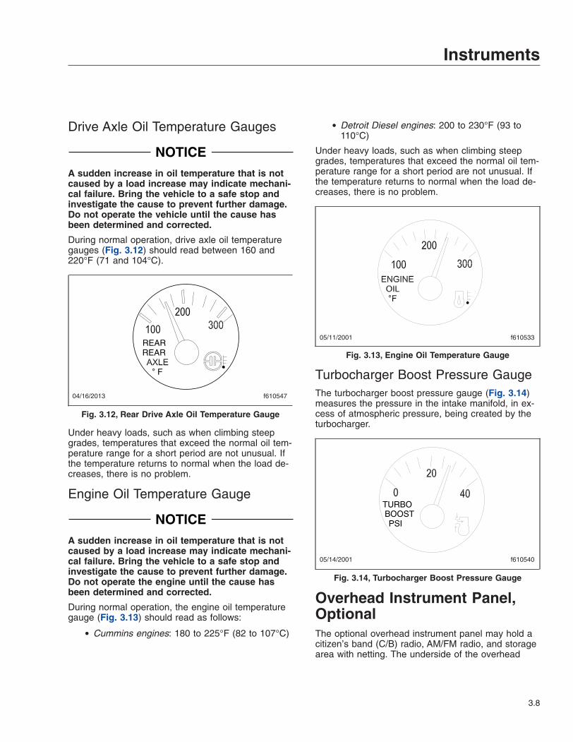
Drive Axle Oil Temperature Gauges
NOTICEA sudden increase in oil temperature that is notcaused by a load increase may indicate mechani-cal failure. Bring the vehicle to a safe stop andinvestigate the cause to prevent further damage.Do not operate the vehicle until the cause hasbeen determined and corrected.
During normal operation, drive axle oil temperaturegauges (Fig. 3.12) should read between 160 and220°F (71 and 104°C).
Under heavy loads, such as when climbing steepgrades, temperatures that exceed the normal oil tem-perature range for a short period are not unusual. Ifthe temperature returns to normal when the load de-creases, there is no problem.
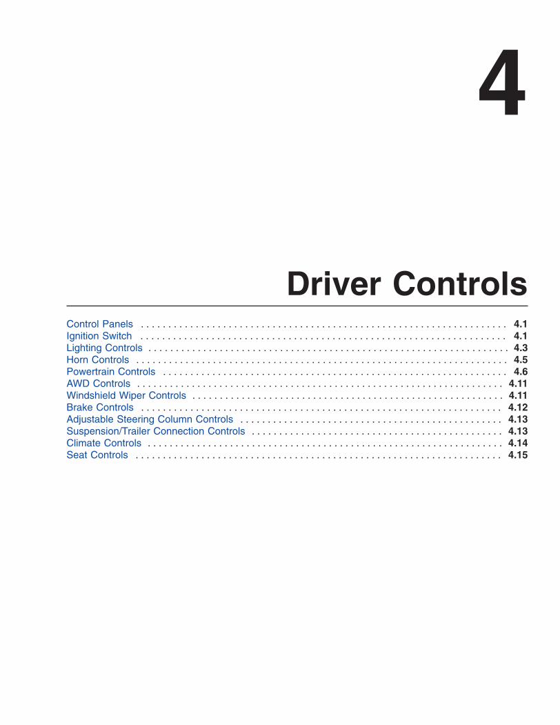
Engine Oil Temperature Gauge
NOTICEA sudden increase in oil temperature that is notcaused by a load increase may indicate mechani-cal failure. Bring the vehicle to a safe stop andinvestigate the cause to prevent further damage.Do not operate the engine until the cause hasbeen determined and corrected.
During normal operation, the engine oil temperaturegauge (Fig. 3.13) should read as follows:
• Cummins engines: 180 to 225°F (82 to 107°C)
• Detroit Diesel engines: 200 to 230°F (93 to110°C)
Under heavy loads, such as when climbing steepgrades, temperatures that exceed the normal oil tem-perature range for a short period are not unusual. Ifthe temperature returns to normal when the load de-creases, there is no problem.
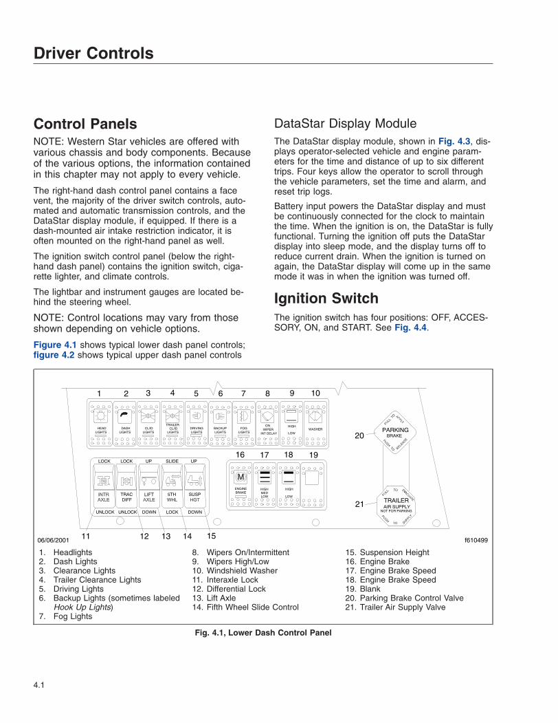
Turbocharger Boost Pressure GaugeThe turbocharger boost pressure gauge (Fig. 3.14)measures the pressure in the intake manifold, in ex-cess of atmospheric pressure, being created by theturbocharger.
Overhead Instrument Panel,OptionalThe optional overhead instrument panel may hold acitizen’s band (C/B) radio, AM/FM radio, and storagearea with netting. The underside of the overhead
04/16/2013 f610547
REARREAR
F
Fig. 3.12, Rear Drive Axle Oil Temperature Gauge
05/11/2001 f610533
Fig. 3.13, Engine Oil Temperature Gauge
05/14/2001 f610540
Fig. 3.14, Turbocharger Boost Pressure Gauge
Instruments
3.8

console also holds the sun visors and the optionaldome/reading light assembly. For more informationon the dome/reading light assembly, see Chapter 7.
Instruments
3.9
4
Driver ControlsControl Panels . . . . . . . . . . . . . . . . . . . . . . . . . . . . . . . . . . . . . . . . . . . . . . . . . . . . . . . . . . . . . . . . . . . 4.1Ignition Switch . . . . . . . . . . . . . . . . . . . . . . . . . . . . . . . . . . . . . . . . . . . . . . . . . . . . . . . . . . . . . . . . . . . 4.1Lighting Controls . . . . . . . . . . . . . . . . . . . . . . . . . . . . . . . . . . . . . . . . . . . . . . . . . . . . . . . . . . . . . . . . . . 4.3Horn Controls . . . . . . . . . . . . . . . . . . . . . . . . . . . . . . . . . . . . . . . . . . . . . . . . . . . . . . . . . . . . . . . . . . . . 4.5Powertrain Controls . . . . . . . . . . . . . . . . . . . . . . . . . . . . . . . . . . . . . . . . . . . . . . . . . . . . . . . . . . . . . . . 4.6AWD Controls . . . . . . . . . . . . . . . . . . . . . . . . . . . . . . . . . . . . . . . . . . . . . . . . . . . . . . . . . . . . . . . . . . . 4.11Windshield Wiper Controls . . . . . . . . . . . . . . . . . . . . . . . . . . . . . . . . . . . . . . . . . . . . . . . . . . . . . . . . . 4.11Brake Controls . . . . . . . . . . . . . . . . . . . . . . . . . . . . . . . . . . . . . . . . . . . . . . . . . . . . . . . . . . . . . . . . . . 4.12Adjustable Steering Column Controls . . . . . . . . . . . . . . . . . . . . . . . . . . . . . . . . . . . . . . . . . . . . . . . . 4.13Suspension/Trailer Connection Controls . . . . . . . . . . . . . . . . . . . . . . . . . . . . . . . . . . . . . . . . . . . . . . 4.13Climate Controls . . . . . . . . . . . . . . . . . . . . . . . . . . . . . . . . . . . . . . . . . . . . . . . . . . . . . . . . . . . . . . . . . 4.14Seat Controls . . . . . . . . . . . . . . . . . . . . . . . . . . . . . . . . . . . . . . . . . . . . . . . . . . . . . . . . . . . . . . . . . . . 4.15
Control PanelsNOTE: Western Star vehicles are offered withvarious chassis and body components. Becauseof the various options, the information containedin this chapter may not apply to every vehicle.
The right-hand dash control panel contains a facevent, the majority of the driver switch controls, auto-mated and automatic transmission controls, and theDataStar display module, if equipped. If there is adash-mounted air intake restriction indicator, it isoften mounted on the right-hand panel as well.
The ignition switch control panel (below the right-hand dash panel) contains the ignition switch, ciga-rette lighter, and climate controls.
The lightbar and instrument gauges are located be-hind the steering wheel.
NOTE: Control locations may vary from thoseshown depending on vehicle options.
Figure 4.1 shows typical lower dash panel controls;figure 4.2 shows typical upper dash panel controls
DataStar Display ModuleThe DataStar display module, shown in Fig. 4.3, dis-plays operator-selected vehicle and engine param-eters for the time and distance of up to six differenttrips. Four keys allow the operator to scroll throughthe vehicle parameters, set the time and alarm, andreset trip logs.
Battery input powers the DataStar display and mustbe continuously connected for the clock to maintainthe time. When the ignition is on, the DataStar is fullyfunctional. Turning the ignition off puts the DataStardisplay into sleep mode, and the display turns off toreduce current drain. When the ignition is turned onagain, the DataStar display will come up in the samemode it was in when the ignition was turned off.
Ignition SwitchThe ignition switch has four positions: OFF, ACCES-SORY, ON, and START. See Fig. 4.4.
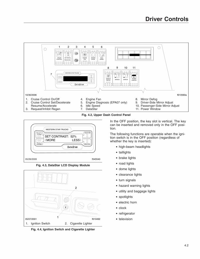
f61049906/06/2001
1 2 3 4 5 6 7 8 9 10
11 12 13 14 15
16 17 18 19
20
21
1. Headlights2. Dash Lights3. Clearance Lights4. Trailer Clearance Lights5. Driving Lights6. Backup Lights (sometimes labeled
Hook Up Lights)7. Fog Lights
8. Wipers On/Intermittent9. Wipers High/Low10. Windshield Washer11. Interaxle Lock12. Differential Lock13. Lift Axle14. Fifth Wheel Slide Control
15. Suspension Height16. Engine Brake17. Engine Brake Speed18. Engine Brake Speed19. Blank20. Parking Brake Control Valve21. Trailer Air Supply Valve
Fig. 4.1, Lower Dash Control Panel
Driver Controls
4.1
In the OFF position, the key slot is vertical. The keycan be inserted and removed only in the OFF posi-tion.
The following functions are operable when the igni-tion switch is in the OFF position (regardless ofwhether the key is inserted):
• high-beam headlights
• taillights
• brake lights
• road lights
• dome lights
• clearance lights
• turn signals
• hazard warning lights
• utility and baggage lights
• spotlights
• electric horn
• clock
• refrigerator
• television
f610560a
1 2 4 5 6
7
8 9 10 11
10/30/2006
3
1. Cruise Control On/Off2. Cruise Control Set/Decelerate
Resume/Accelerate3. Request/Inhibit Regen
4. Engine Fan5. Engine Diagnosis (EPA07 only)6. Idle Speed7. DataStar
8. Mirror Defog9. Driver-Side Mirror Adjust10. Passenger-Side Mirror Adjust11. Power Window
Fig. 4.2, Upper Dash Control Panel
05/26/2009 f545540
SET CONTRAST: 52% MORE LESS
Fig. 4.3, DataStar LCD Display Module
05/07/2001 f6104921
2
1. Ignition Switch 2. Cigarette Lighter
Fig. 4.4, Ignition Switch and Cigarette Lighter
Driver Controls
4.2
Turn the key counterclockwise to the ACCESSORYposition. In addition to all the functions that are oper-able with the ignition switch in the OFF position, thefollowing functions are operable when the switch is inthe ACCESSORY position:
• radio/stereo system
• heater and A/C fan
• mirror defog
• windshield wipers
• beacons
• power windows
• windshield washer
• outside air temperature display
Turn the key clockwise past the OFF position to theON position. With the switch in the ON position, thewarning and indicator lamps illuminate. Wait for threeseconds before starting the engine.
Turn the key clockwise past the ON position to theSTART position and start the engine. Do not operatethe starter longer than thirty seconds, and wait atleast two minutes between starting attempts to allowthe starter to cool. Release the key the moment theengine starts.
Switching on the ignition and releasing the parkingbrake automatically activates the daytime runninglights, if equipped. The daytime running lights willoperate until the parking brake is applied or theheadlights are turned on.
Lighting ControlsIMPORTANT: Unless otherwise noted below,press the upper half of the switch to activate thedesired light(s). Press the lower half of theswitch to turn the light(s) off.
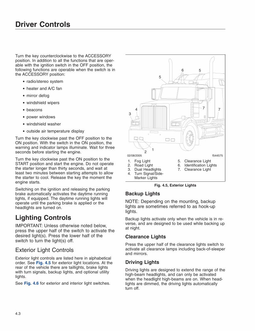
Exterior Light ControlsExterior light controls are listed here in alphabeticalorder. See Fig. 4.5 for exterior light locations. At therear of the vehicle there are taillights, brake lightswith turn signals, backup lights, and optional utilitylights.
See Fig. 4.6 for exterior and interior light switches.
Backup Lights
NOTE: Depending on the mounting, backuplights are sometimes referred to as hook-uplights.
Backup lights activate only when the vehicle is in re-verse, and are designed to be used while backing upat night.
Clearance LightsPress the upper half of the clearance lights switch toactivate all clearance lamps including back-of-sleeperand mirrors.
Driving LightsDriving lights are designed to extend the range of thehigh-beam headlights, and can only be activatedwhen the headlight high-beams are on. When head-lights are dimmed, the driving lights automaticallyturn off.
02/08/2005 f544575
12
34
5
6 5
7 7
1. Fog Light2. Road Light3. Dual Headlights4. Turn Signal/Side-
Marker Lights
5. Clearance Light6. Identification Lights7. Clearance Light
Fig. 4.5, Exterior Lights
Driver Controls
4.3

Fog LightsFog lights are designed to reduce glare in foggy con-ditions. The headlights must be on and set on lowbeam for the fog lights to activate.
Hazard Warning LightsThe hazard flasher switch is located underneath theturn signal lever, as shown in Fig. 4.7. Pull the haz-ard light switch tab out to activate all of the turn sig-nal lights and both of the telltales on the lightbar willflash. To cancel the hazard lights, move the turn sig-nal lever up or down.
Western Star vehicles may be equipped with an op-tional hazard light switch located on the right-handdash panel. To operate the hazard lights, press theupper half of the switch. To cancel the hazard lights,press the lower half of the switch.
Headlight InterruptWhen the headlight interrupt switch is activated, thedaytime running lights blink. The headlight interruptswitch only operates when the headlights are on.
HeadlightsThe headlight switch is operated by pushing theupper half of the switch once for the parking lights,illuminating the taillights and side marker lamps onboth the tractor and trailer. Pressing the upper half ofthe switch a second time activates the headlights. Anaudible warning will sound if the lights are left onwhen the ignition is turned off.
High-Beam HeadlightsWith the low-beam headlights on, push the button onthe end of the turn-signal lever to turn on the high-beam headlights. See Fig. 4.7. Push the buttonagain to turn the high-beams off.
FOGLIGHTS
DRIVINGLIGHTS
CL / IDLIGHTS
HEADLIGHTS
HEAD LT.INTERRUPT
CL / IDLIGHTS
SLEEPERLIGHTS
DASHLIGHTS
TRAILER
BACKUPLIGHTS
08/22/2011
1
9 8 7 6
2 3 4 5
f545815
1. Headlights Switch2. Tractor Clearance Lights Switch3. Driving Lights Switch4. Fog Lights Switch
5. Backup Lights Switch (sometimeslabeled Hook Up Lights)
6. Headlight Interrupt Switch
7. Trailer Clearance Lights Switch8. Sleeper Lights Switch9. Dash Lights Switch
Fig. 4.6, Exterior and Interior Light Switches
Driver Controls
4.4
When the high-beam headlights are on, a blue lightilluminates on the lightbar.
Trailer Clearance LightsThe trailer clearance lights switch activates the trailerclearance lamps independent of the tractor lamps.
Turn SignalsThe turn-signal switch is typically a non-cancelingcombination turn-signal, hazard, and headlight-dimmer unit that mounts to a bracket on the left sideof the steering column. See Fig. 4.7.
Moving the turn signal switch down turns on the left-turn signal; moving it up turns on the right-turn sig-nal. To manually cancel the signal, move the lever tothe neutral position.
When a turn signal is activated, a green telltale lightflashes on the lightbar.
On a self-canceling turn signal switch, the switch au-tomatically returns to the neutral position when thesteering wheel returns to the straight ahead positionafter a turn.
Interior Light ControlsThe cab is equipped with a dome light and optionalhigh-intensity reading lights. The sleeper section isequipped with accessory lights and high-intensityreading lights. Baggage compartments may beequipped with accessory lights.
When the panel lights are on, most switch icons arebacklit with a colored light to allow the driver to findswitches more easily in the dark. When a switch isactivated, the lightbar on the switch is backlit with acolored light.
Dash LightsThe dash lights switch is operated by pushing theupper half of the switch and holding to obtain thebrightness desired. Pushing and holding the lowerhalf of the switch will dim the dash lights.
Overhead Console LightsIn cabs with an overhead console, there is an op-tional overhead light assembly containing a diffusedome light and clear reading lights.
Rear Dome LightThe standard rear dome light is installed on the backof the cab above the rear window.
Horn ControlsAir HornThe air horn is controlled by a wire lanyard hangingfrom the center of the overhead console. Pull down-ward on the lanyard to sound the air horn.
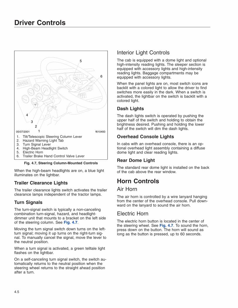
Electric HornThe electric horn button is located in the center ofthe steering wheel. See Fig. 4.7. To sound the horn,press down on the button. The horn will sound aslong as the button is pressed, up to 60 seconds.
05/07/2001 f61049312
3
4
5
6
1. Tilt/Telescopic Steering Column Lever2. Hazard Warning Light Tab3. Turn Signal Lever4. High-Beam Headlight Switch5. Electric Horn6. Trailer Brake Hand Control Valve Lever
Fig. 4.7, Steering Column-Mounted Controls
Driver Controls
4.5
Powertrain ControlsAftertreatment System RegenSwitchesNOTE: See Chapter 11 for detailed informationabout the operation of the regeneration (regen)switches and the aftertreatment system (ATS).
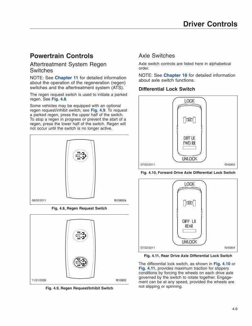
The regen request switch is used to initiate a parkedregen. See Fig. 4.8.
Some vehicles may be equipped with an optionalregen request/inhibit switch; see Fig. 4.9. To requesta parked regen, press the upper half of the switch.To stop a regen in progress or prevent the start of aregen, press the lower half of the switch. Regen willnot occur until the switch is no longer active.
Axle SwitchesAxle switch controls are listed here in alphabeticalorder.
NOTE: See Chapter 16 for detailed informationabout axle switch functions.
Differential Lock Switch
The differential lock switch, as shown in Fig. 4.10 orFig. 4.11, provides maximum traction for slipperyconditions by forcing the wheels on each drive axlegoverned by the switch to rotate together. Engage-ment can be at any speed, provided the wheels arenot slipping or spinning.
08/02/2011 f610852a
Fig. 4.8, Regen Request Switch
11/01/2006 f610852
Fig. 4.9, Regen Request/Inhibit Switch
07/22/2011 f545803
Fig. 4.10, Forward Drive Axle Differential Lock Switch
07/22/2011 f545804
Fig. 4.11, Rear Drive Axle Differential Lock Switch
Driver Controls
4.6

Interaxle Lock SwitchThe interaxle lock switch allows the driver to lock thedrive axles together, causing the drive axle shafts torotate together. See Fig. 4.12. Use this feature onlyunder adverse road conditions where greater tractionis needed.
Leave the control in the UNLOCK position for normalhighway operation. When a spinning or slipping ac-tion occurs at any of the drive wheels, press theupper half of the switch to LOCK the differential andprevent the wheels from spinning.
NOTICEDo not shift into LOCK while the rear wheels arespinning. Come to a halt before engaging to pre-vent damage to the interaxle and main differen-tials.
Do not permit rear wheels to spin freely for morethan ten seconds when traction is lost. Shift intoLOCK to prevent damage to the interaxle andmain differentials.
Lift Axle SwitchThe lift axle switch controls the lift axle operation.See Fig. 4.13. Pushing the upper half of the switchwill lower the lift axle.
Cruise Control SwitchesNOTE: See Chapter 10 for detailed informationabout cruise control operation.
On/Off SwitchPress the upper half of the cruise control on/offswitch to activate it. See Fig. 4.14.
NOTE: Cruise control is canceled if the brake orclutch pedal is depressed, or engine speeddrops below 1200 rpm.
07/22/2011 f545802
Fig. 4.12, Interaxle Lock Switch
08/22/2011 f545817
LIFTAXLE
Fig. 4.13, Lift Axle Switch
07/15/2011 f545790
CRUISECONTROL
SET/DECEL
RES/ACCEL
1. Cruise Control On/Off Switch2. Cruise Control Set/Resume Switch
Fig. 4.14, Cruise Control Switches
Driver Controls
4.7

Set/Decelerate/Resume/Accelerate SwitchThe set/decelerate/resume/accelerate switch canonly be used when cruise control has been activated.See Fig. 4.14.
Press the upper half of the switch momentarily to setthe cruise speed (with the engine running at the de-sired speed). Press and hold the upper half of theswitch to decelerate slowly. Release the switch whenthe desired speed is reached.
Press the lower half of the switch momentarily to re-sume the previously set cruise speed. Press thelower half of the switch and hold to accelerate slowly.Release the switch when the desired speed isachieved.
NOTICEWhen the cruise control is engaged, do not at-tempt to shift gears without using the clutchpedal. Failure to follow this precaution will resultin a temporarily uncontrolled increase in enginespeed. Transmission damage and gear strippingcould result.
Engine Brake SwitchesNOTE: See Chapter 10 for detailed informationabout engine brake operation.
Whenever vehicle braking is required on good roadconditions, the engine brake may be used in con-junction with the service brakes. There is no timelimit for operation of the engine brake. However, anengine brake does not provide the precise control of,and is not a substitute for, service brakes.
Two dash-mounted switches control the enginebrake:
• The ENGINE BRAKE switch is used to turn theengine brake on and off. See Fig. 4.15.
• The HIGH/MED/LOW engine brake intensityswitch (HIGH/LOW in some cases) controls theamount of engine braking. When the enginebrake is on, the status bar illuminates, indicat-ing the current intensity setting.
Engine Diagnostic Switch (EPA07vehicles)The engine diagnostic switch is used to signal theengine ECM to flash codes on the indicator light.Press the upper half of the switch once to activate it.See Fig. 4.16.
Engine Fan SwitchPress the upper half of the engine fan switch to over-ride the automatic fan control and cause the enginefan to run continuously. See Fig. 4.17. This switch isintended for temporary use, or if the automatic fancontrol fails. Press the lower half of the switch to re-turn to automatic fan control.
07/15/2011 f545791
ENGINEBRAKE
M
HIGHMEDLOW
1. Engine Brake On/Off2. Engine Brake Intensity Switch
Fig. 4.15, Engine Brake Switches
08/22/2011 f545819
ENGINEDIAGN
Fig. 4.16, Engine Diagnostic Switch
Driver Controls
4.8
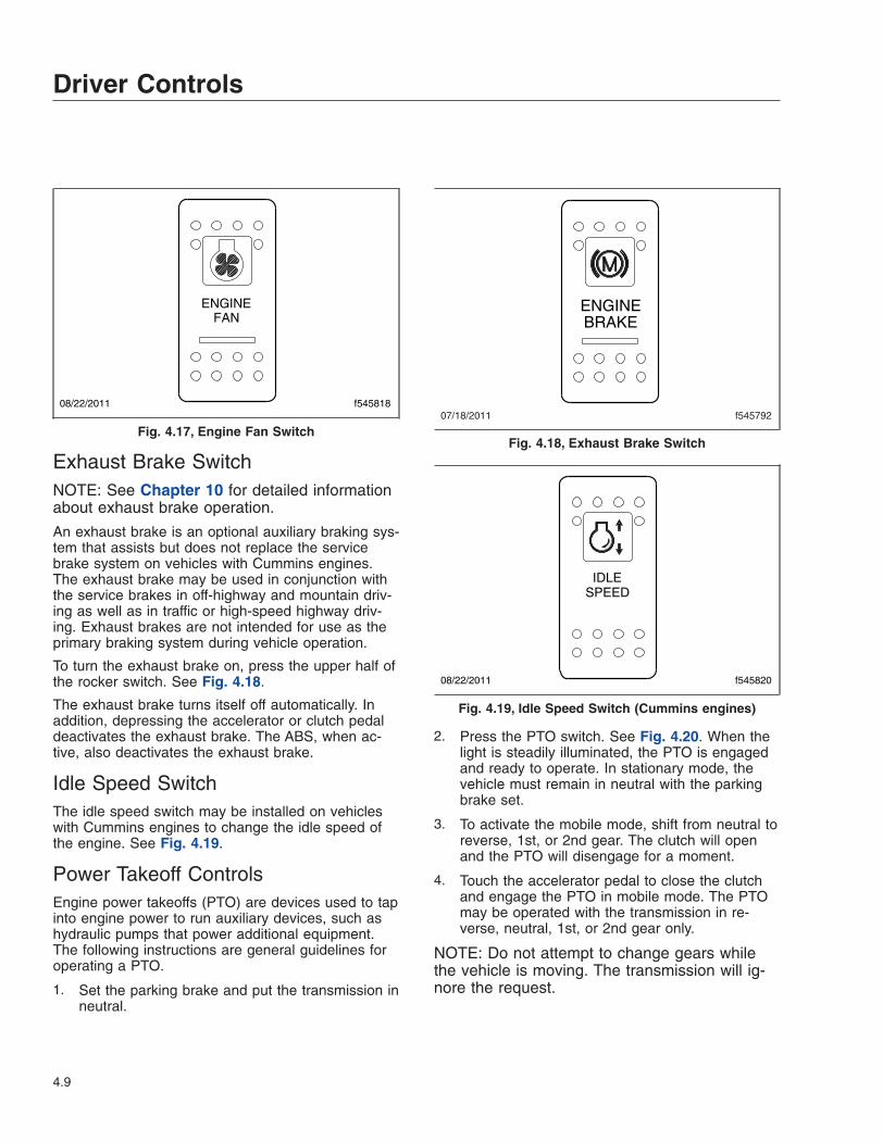
Exhaust Brake SwitchNOTE: See Chapter 10 for detailed informationabout exhaust brake operation.
An exhaust brake is an optional auxiliary braking sys-tem that assists but does not replace the servicebrake system on vehicles with Cummins engines.The exhaust brake may be used in conjunction withthe service brakes in off-highway and mountain driv-ing as well as in traffic or high-speed highway driv-ing. Exhaust brakes are not intended for use as theprimary braking system during vehicle operation.
To turn the exhaust brake on, press the upper half ofthe rocker switch. See Fig. 4.18.
The exhaust brake turns itself off automatically. Inaddition, depressing the accelerator or clutch pedaldeactivates the exhaust brake. The ABS, when ac-tive, also deactivates the exhaust brake.
Idle Speed SwitchThe idle speed switch may be installed on vehicleswith Cummins engines to change the idle speed ofthe engine. See Fig. 4.19.
Power Takeoff ControlsEngine power takeoffs (PTO) are devices used to tapinto engine power to run auxiliary devices, such ashydraulic pumps that power additional equipment.The following instructions are general guidelines foroperating a PTO.
1. Set the parking brake and put the transmission inneutral.
2. Press the PTO switch. See Fig. 4.20. When thelight is steadily illuminated, the PTO is engagedand ready to operate. In stationary mode, thevehicle must remain in neutral with the parkingbrake set.
3. To activate the mobile mode, shift from neutral toreverse, 1st, or 2nd gear. The clutch will openand the PTO will disengage for a moment.
4. Touch the accelerator pedal to close the clutchand engage the PTO in mobile mode. The PTOmay be operated with the transmission in re-verse, neutral, 1st, or 2nd gear only.
NOTE: Do not attempt to change gears whilethe vehicle is moving. The transmission will ig-nore the request.
08/22/2011 f545818
ENGINEFAN
Fig. 4.17, Engine Fan Switch07/18/2011 f545792
ENGINEBRAKE
Fig. 4.18, Exhaust Brake Switch
08/22/2011 f545820
SPEEDIDLE
Fig. 4.19, Idle Speed Switch (Cummins engines)
Driver Controls
4.9
5. To end the mobile mode, bring the vehicle to astop. The clutch will open and shut down powerto the PTO.
6. To resume stationary mode, shift to neutral. ThePTO will engage.
7. To end stationary mode, press the dash switch.When the light in the switch goes out, power tothe PTO is shut off.
Transmission ControlsManual Transmissions
NOTE: See Chapter 14 for complete manualtransmission operating instructions.
if equipped, the transmission range control and split-ter valves are attached to the gear shift knob.
To operate a range-shift transmission, move the shiftknob through all the low-range gear positions andthen pull the range-preselection lever up to move intothe high-range ratios. Use the same shift knob posi-tions in both the low and high ranges.
Dependent on the transmission model, some ratioscan be split using the splitter-control button (locatedon the side of the shift knob).
Eaton Automated Transmissions
NOTE: See Chapter 15 for complete automatedtransmission operating instructions.
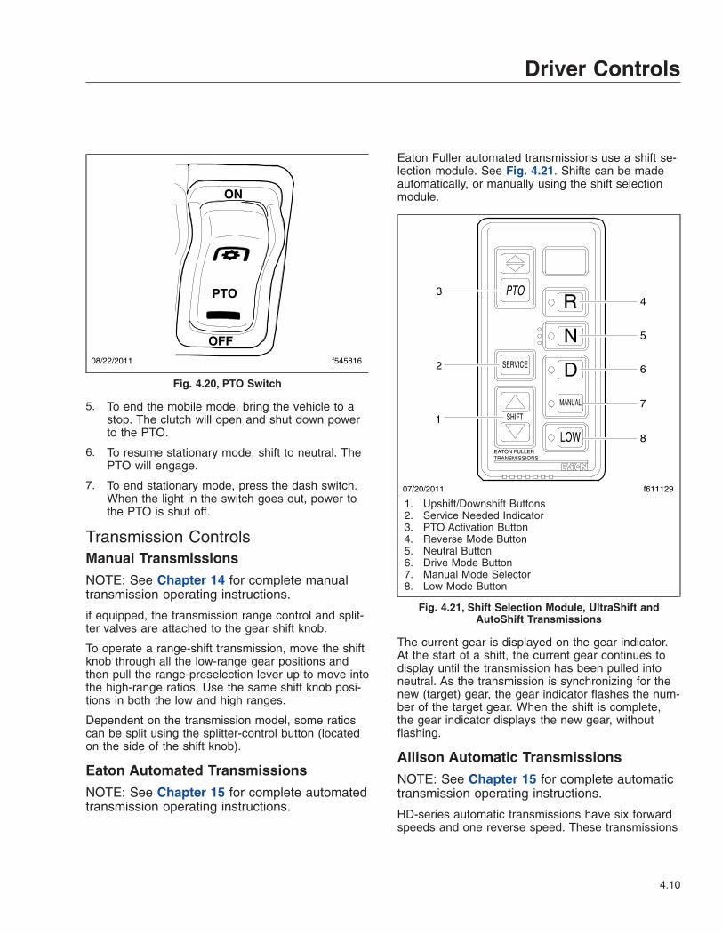
Eaton Fuller automated transmissions use a shift se-lection module. See Fig. 4.21. Shifts can be madeautomatically, or manually using the shift selectionmodule.
The current gear is displayed on the gear indicator.At the start of a shift, the current gear continues todisplay until the transmission has been pulled intoneutral. As the transmission is synchronizing for thenew (target) gear, the gear indicator flashes the num-ber of the target gear. When the shift is complete,the gear indicator displays the new gear, withoutflashing.
Allison Automatic Transmissions
NOTE: See Chapter 15 for complete automatictransmission operating instructions.
HD-series automatic transmissions have six forwardspeeds and one reverse speed. These transmissions
ON
OFF
PTO
08/22/2011 f545816
Fig. 4.20, PTO Switch
SERVICE
SHIFT
MANUAL
EATON FULLERTRANSMISSIONS
LOW
D
N
RPTO
07/20/2011 f611129
1
4
2
3
5
6
7
8
1. Upshift/Downshift Buttons2. Service Needed Indicator3. PTO Activation Button4. Reverse Mode Button5. Neutral Button6. Drive Mode Button7. Manual Mode Selector8. Low Mode Button
Fig. 4.21, Shift Selection Module, UltraShift andAutoShift Transmissions
Driver Controls
4.10
have electronic shift controls that can be pro-grammed to allow the use of different numbers ofgeared speeds. See Fig. 4.22.
AWD ControlsThe AWD switch allows the driver to direct power tothe steer axle. For more information about transfercases and driven steer axles, see Chapter 16.
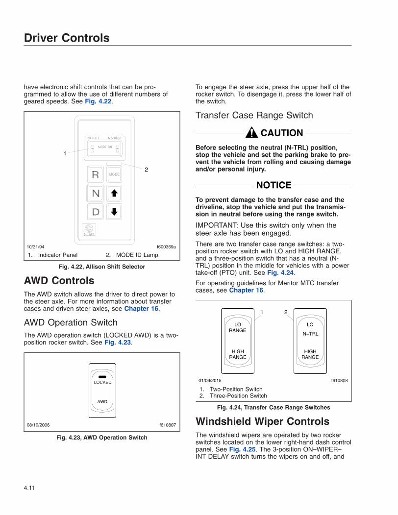
AWD Operation SwitchThe AWD operation switch (LOCKED AWD) is a two-position rocker switch. See Fig. 4.23.
To engage the steer axle, press the upper half of therocker switch. To disengage it, press the lower half ofthe switch.
Transfer Case Range Switch
CAUTIONBefore selecting the neutral (N-TRL) position,stop the vehicle and set the parking brake to pre-vent the vehicle from rolling and causing damageand/or personal injury.
NOTICETo prevent damage to the transfer case and thedriveline, stop the vehicle and put the transmis-sion in neutral before using the range switch.
IMPORTANT: Use this switch only when thesteer axle has been engaged.
There are two transfer case range switches: a two-position rocker switch with LO and HIGH RANGE,and a three-position switch that has a neutral (N-TRL) position in the middle for vehicles with a powertake-off (PTO) unit. See Fig. 4.24.
For operating guidelines for Meritor MTC transfercases, see Chapter 16.
Windshield Wiper ControlsThe windshield wipers are operated by two rockerswitches located on the lower right-hand dash controlpanel. See Fig. 4.25. The 3-position ON–WIPER–INT DELAY switch turns the wipers on and off, and
10/31/94 f600369a
1
2
1. Indicator Panel 2. MODE ID Lamp
Fig. 4.22, Allison Shift Selector
08/10/2006 f610807
LOCKED
AWD
Fig. 4.23, AWD Operation Switch
1
f610808
LO
RANGEHIGH
RANGELO
RANGEHIGH
N−TRL
01/06/2015
2
1. Two-Position Switch2. Three-Position Switch
Fig. 4.24, Transfer Case Range Switches
Driver Controls
4.11
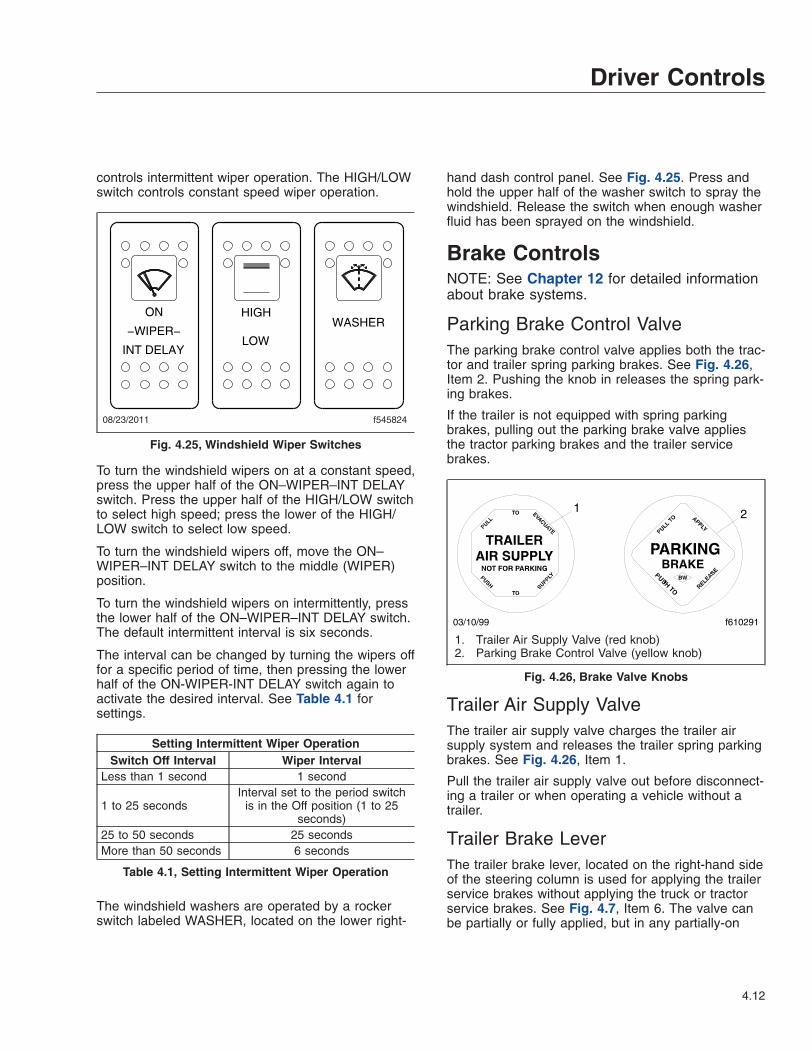
controls intermittent wiper operation. The HIGH/LOWswitch controls constant speed wiper operation.
To turn the windshield wipers on at a constant speed,press the upper half of the ON–WIPER–INT DELAYswitch. Press the upper half of the HIGH/LOW switchto select high speed; press the lower of the HIGH/LOW switch to select low speed.
To turn the windshield wipers off, move the ON–WIPER–INT DELAY switch to the middle (WIPER)position.
To turn the windshield wipers on intermittently, pressthe lower half of the ON–WIPER–INT DELAY switch.The default intermittent interval is six seconds.
The interval can be changed by turning the wipers offfor a specific period of time, then pressing the lowerhalf of the ON-WIPER-INT DELAY switch again toactivate the desired interval. See Table 4.1 forsettings.
Setting Intermittent Wiper OperationSwitch Off Interval Wiper Interval
Less than 1 second 1 second
1 to 25 secondsInterval set to the period switch
is in the Off position (1 to 25seconds)
25 to 50 seconds 25 secondsMore than 50 seconds 6 seconds
Table 4.1, Setting Intermittent Wiper Operation
The windshield washers are operated by a rockerswitch labeled WASHER, located on the lower right-
hand dash control panel. See Fig. 4.25. Press andhold the upper half of the washer switch to spray thewindshield. Release the switch when enough washerfluid has been sprayed on the windshield.
Brake ControlsNOTE: See Chapter 12 for detailed informationabout brake systems.
Parking Brake Control ValveThe parking brake control valve applies both the trac-tor and trailer spring parking brakes. See Fig. 4.26,Item 2. Pushing the knob in releases the spring park-ing brakes.
If the trailer is not equipped with spring parkingbrakes, pulling out the parking brake valve appliesthe tractor parking brakes and the trailer servicebrakes.
Trailer Air Supply ValveThe trailer air supply valve charges the trailer airsupply system and releases the trailer spring parkingbrakes. See Fig. 4.26, Item 1.
Pull the trailer air supply valve out before disconnect-ing a trailer or when operating a vehicle without atrailer.
Trailer Brake LeverThe trailer brake lever, located on the right-hand sideof the steering column is used for applying the trailerservice brakes without applying the truck or tractorservice brakes. See Fig. 4.7, Item 6. The valve canbe partially or fully applied, but in any partially-on
08/23/2011 f545824
ON HIGHWASHER
LOW−WIPER−
INT DELAY
Fig. 4.25, Windshield Wiper Switches
f610291
1 2
03/10/99
1. Trailer Air Supply Valve (red knob)2. Parking Brake Control Valve (yellow knob)
Fig. 4.26, Brake Valve Knobs
Driver Controls
4.12

position it will be overridden by a full application ofthe service brake pedal. Moving the lever down ap-plies the trailer brakes, while moving it up releasesthe trailer brakes. The lever will automatically returnto the up position when it is released.
Antilock Braking SystemThe Meritor WABCO® Antilock Braking System(ABS) controls wheel speed during emergency stopsor wheel lock situations.
During emergency or reduced-traction stops, fullydepress the brake pedal until the vehicle comes to asafe stop. Do not pump the brake pedal. With thebrake pedal fully depressed, the ABS will control allwheels to provide steering control and a reducedbraking distance.
Vehicles with ABS may have Automatic Traction Con-trol (ATC). The ATC system automatically limitswheel spin during reduced-traction situations. If thevehicle has ATC, there will be an ATC switch locatedon the right-hand control panel. See Fig. 4.27.Pressing the switch will temporarily allow more drivewheel spin. Pressing the switch again will cause thesystem to go back to normal operation.
NOTICEThe ATC option is intended to be used underspecific slippery conditions that require momen-tary increased wheel spin. Using this option for
an extended period of time may damage the ve-hicle brake system.
Adjustable Steering ColumnControlsAdjust the seat to the desired ride position, then tiltor telescope the steering column as needed usingthe steering column lever in Fig. 4.7.
To tilt the steering column, pull the lever up towardthe driver. Tilt the wheel to the desired position andrelease the lever.
To telescope the steering column, push the leverdown (away from the driver) and pull or push thesteering wheel to the desired position. Release thelever to lock the steering column in place.
WARNINGMake sure that the control lever is back in theneutral position and the steering column islocked before driving the vehicle. Never tilt thecolumn while driving the vehicle. Doing so couldcause loss of vehicle control, personal injury,and property damage.
Suspension/Trailer ConnectionControlsAir-Suspension Dump Control Switch
NOTICEDo not operate the vehicle over uneven groundsuch as ramps, speed bumps, curbs, etc., withthe air springs deflated. Doing this may lead toair bag separation from the piston, preventing thesuspension air springs from inflating.
The suspension dump switch allows the air in the airsuspension to be quickly exhausted, lowering therear of the vehicle. Fig. 4.28. This makes it easier toconnect to, or disconnect from, a trailer.
05/15/2001 f610494
Fig. 4.27, ATC Switch
Driver Controls
4.13
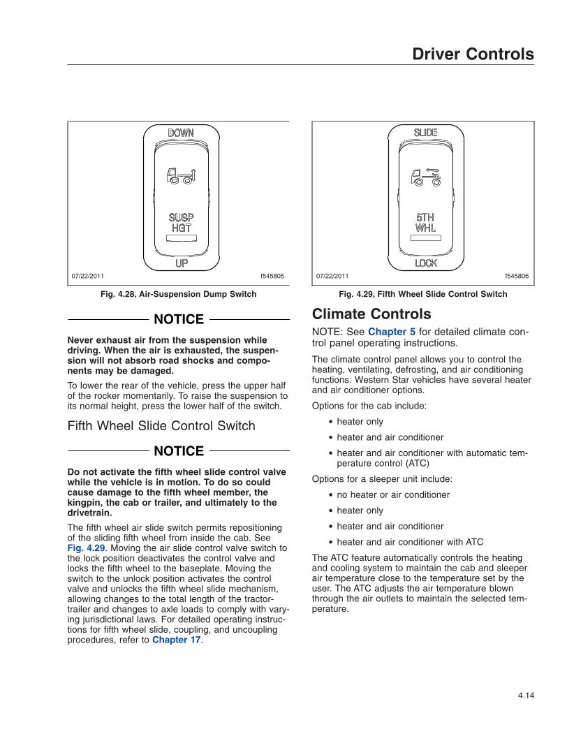
NOTICENever exhaust air from the suspension whiledriving. When the air is exhausted, the suspen-sion will not absorb road shocks and compo-nents may be damaged.
To lower the rear of the vehicle, press the upper halfof the rocker momentarily. To raise the suspension toits normal height, press the lower half of the switch.
Fifth Wheel Slide Control Switch
NOTICEDo not activate the fifth wheel slide control valvewhile the vehicle is in motion. To do so couldcause damage to the fifth wheel member, thekingpin, the cab or trailer, and ultimately to thedrivetrain.
The fifth wheel air slide switch permits repositioningof the sliding fifth wheel from inside the cab. SeeFig. 4.29. Moving the air slide control valve switch tothe lock position deactivates the control valve andlocks the fifth wheel to the baseplate. Moving theswitch to the unlock position activates the controlvalve and unlocks the fifth wheel slide mechanism,allowing changes to the total length of the tractor-trailer and changes to axle loads to comply with vary-ing jurisdictional laws. For detailed operating instruc-tions for fifth wheel slide, coupling, and uncouplingprocedures, refer to Chapter 17.
Climate ControlsNOTE: See Chapter 5 for detailed climate con-trol panel operating instructions.
The climate control panel allows you to control theheating, ventilating, defrosting, and air conditioningfunctions. Western Star vehicles have several heaterand air conditioner options.
Options for the cab include:
• heater only
• heater and air conditioner
• heater and air conditioner with automatic tem-perature control (ATC)
Options for a sleeper unit include:
• no heater or air conditioner
• heater only
• heater and air conditioner
• heater and air conditioner with ATC
The ATC feature automatically controls the heatingand cooling system to maintain the cab and sleeperair temperature close to the temperature set by theuser. The ATC adjusts the air temperature blownthrough the air outlets to maintain the selected tem-perature.
07/22/2011 f545805
Fig. 4.28, Air-Suspension Dump Switch
07/22/2011 f545806
Fig. 4.29, Fifth Wheel Slide Control Switch
Driver Controls
4.14
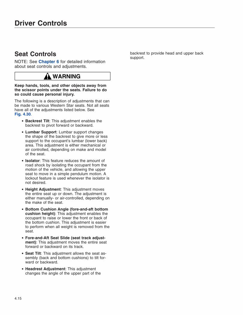
Seat ControlsNOTE: See Chapter 6 for detailed informationabout seat controls and adjustments.
WARNINGKeep hands, tools, and other objects away fromthe scissor points under the seats. Failure to doso could cause personal injury.
The following is a description of adjustments that canbe made to various Western Star seats. Not all seatshave all of the adjustments listed below. SeeFig. 4.30.
• Backrest Tilt: This adjustment enables thebackrest to pivot forward or backward.
• Lumbar Support: Lumbar support changesthe shape of the backrest to give more or lesssupport to the occupant’s lumbar (lower back)area. This adjustment is either mechanical orair controlled, depending on make and modelof the seat.
• Isolator: This feature reduces the amount ofroad shock by isolating the occupant from themotion of the vehicle, and allowing the upperseat to move in a simple pendulum motion. Alockout feature is used whenever the isolator isnot desired.
• Height Adjustment: This adjustment movesthe entire seat up or down. The adjustment iseither manually- or air-controlled, depending onthe make of the seat.
• Bottom Cushion Angle (fore-and-aft bottomcushion height): This adjustment enables theoccupant to raise or lower the front or back ofthe bottom cushion. This adjustment is easierto perform when all weight is removed from theseat.
• Fore-and-Aft Seat Slide (seat track adjust-ment): This adjustment moves the entire seatforward or backward on its track.
• Seat Tilt: This adjustment allows the seat as-sembly (back and bottom cushions) to tilt for-ward or backward.
• Headrest Adjustment: This adjustmentchanges the angle of the upper part of the
backrest to provide head and upper backsupport.
Driver Controls
4.15
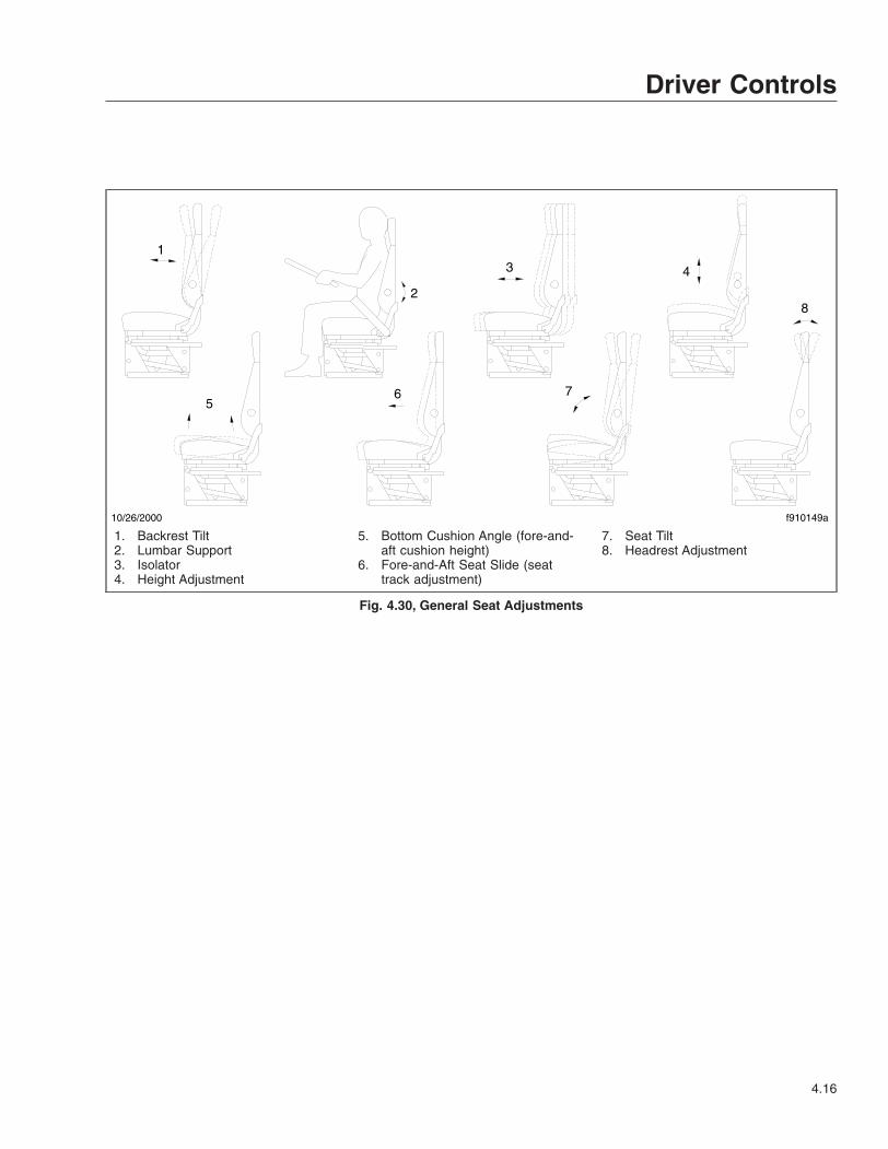
10/26/2000 f910149a
1
2
3 4
56 7
8
1. Backrest Tilt2. Lumbar Support3. Isolator4. Height Adjustment
5. Bottom Cushion Angle (fore-and-aft cushion height)
6. Fore-and-Aft Seat Slide (seattrack adjustment)
7. Seat Tilt8. Headrest Adjustment
Fig. 4.30, General Seat Adjustments
Driver Controls
4.16

5
Climate ControlsClimate Control Options . . . . . . . . . . . . . . . . . . . . . . . . . . . . . . . . . . . . . . . . . . . . . . . . . . . . . . . . . . . . 5.1Cab Climate Control Panels . . . . . . . . . . . . . . . . . . . . . . . . . . . . . . . . . . . . . . . . . . . . . . . . . . . . . . . . 5.1Sleeper Climate Control Panels . . . . . . . . . . . . . . . . . . . . . . . . . . . . . . . . . . . . . . . . . . . . . . . . . . . . . . 5.4
Climate Control OptionsThe climate control panel allows you to control theheating, ventilating, defrosting, and air conditioningfunctions. Western Star vehicles have several heaterand air conditioner options.
Options for the cab include:
• heater only
• heater and air conditioner
• heater and air conditioner with automatic tem-perature control (ATC)
Options for a sleeper unit include:
• no heater or air conditioner
• heater only
• heater and air conditioner
• heater and air conditioner with ATC
The ATC feature automatically controls the heatingand cooling system to maintain the cab and sleeperair temperature close to the temperature set by theuser. The ATC adjusts the air temperature blownthrough the air outlets to maintain the selected tem-perature.
Cab Climate Control PanelsThe standard cab climate control panel has a fanswitch, a temperature control switch, and a modecontrol switch that allows the driver to control heat-ing, cooling, defrosting, and ventilating. The controlpanel may also be equipped with an optional A/Cswitch and/or an optional BUNK switch. See Fig. 5.1.
Vehicles equipped with ATC have an LED display.See Fig. 5.2.
ControlsFan SwitchThe fan switch activates the fan, which forces freshair or recirculated air through the air outlets. The fanswitch has four fan speed settings and an off posi-tion. See Fig. 5.1.
To operate the fan switch, turn the fan switch clock-wise to increase airflow; turn the fan switch counter-clockwise to decrease airflow.
On vehicles equipped with ATC, the AUTO setting onthe fan switch places the heater and air conditionersystem in the automatic fan speed control mode.When the fan switch is set to AUTO, the fan speedwill vary as necessary to maintain the temperatureset by the user.
Temperature Control SwitchTo select the desired temperature:
• Vehicles Without ATC: Turn the switch to theleft (counterclockwise) for cool air, or to theright (clockwise) for hot air.
• Vehicles With ATC: Press and release the rightside of the temperature up/down switch to in-crease the temperature to the desired setting.Press and release the left side of the tempera-ture up/down switch to decrease the tempera-ture to the desired setting. Press and hold thetemperature up/down switch to change the de-sired temperature in large increments.
Mode Control SwitchThe mode control switch allows the driver to controlthe flow of air through the face outlets, the floor out-lets, the defrost (windshield) outlets, or a combinationof these outlets to provide six air selection modes.See Fig. 5.3.
• Face Mode (using recirculating air): Directs allairflow through the face or instrument paneloutlets, using recirculated air.
• Face Mode (using fresh air): Directs all airflowthrough the face or instrument panel outlets,using fresh air.
• Bi-Level Mode: Directs the airflow equally tothe face outlets and the floor outlets.
• Floor Mode: Directs all airflow through the flooroutlets.
• Floor/Defrost Mode: Directs the airflow equallyto the floor outlets and the defrost outlets.
• Defrost Mode: Directs all airflow through thedefrost outlets.
NOTE: The face mode using recirculating air isthe only mode that recirculates the air in thecab. All other modes draw in fresh air from out-side the vehicle.
Climate Controls
5.1

Bunk SwitchThe optional BUNK switch allows the driver to controlthe sleeper heater and air conditioner from the cab.Press the BUNK switch to turn the sleeper heaterand air conditioner on. When the bunk switch is on,the indicator light is on. The sleeper heater and air
conditioner can still be controlled from the sleeperwhen the BUNK switch is on.
Air Conditioner (A/C) SwitchThe air conditioner cools and dehumidifies the airinside the cab. Press the optional A/C switch to turn
f610640
A/CBUNK
1
2 3 4
6 5702/10/2003
1. Fan Off Position2. Fan Switch3. Temperature Control Switch
4. Mode Control Switch5. Air Conditioner Switch
6. Bunk Switch7. Indicator
Fig. 5.1, Cab Climate Control Panel, No ATC
12/13/2002
Automatic Temperature Control
f610628
1
2
3
456
1. Fan Off Position2. LED Display
3. Mode Control Switch4. Bunk Switch (optional)
5. Temperature Up/Down Switch6. Fan Switch
Fig. 5.2, Cab Climate Control Panel With ATC
Climate Controls
5.2
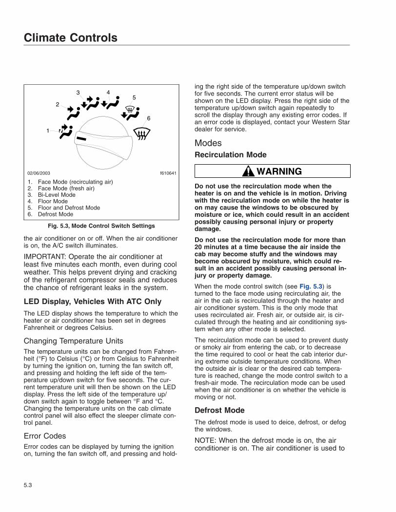
the air conditioner on or off. When the air conditioneris on, the A/C switch illuminates.
IMPORTANT: Operate the air conditioner atleast five minutes each month, even during coolweather. This helps prevent drying and crackingof the refrigerant compressor seals and reducesthe chance of refrigerant leaks in the system.
LED Display, Vehicles With ATC OnlyThe LED display shows the temperature to which theheater or air conditioner has been set in degreesFahrenheit or degrees Celsius.
Changing Temperature UnitsThe temperature units can be changed from Fahren-heit (°F) to Celsius (°C) or from Celsius to Fahrenheitby turning the ignition on, turning the fan switch off,and pressing and holding the left side of the tem-perature up/down switch for five seconds. The cur-rent temperature unit will then be shown on the LEDdisplay. Press the left side of the temperature up/down switch again to toggle between °F and °C.Changing the temperature units on the cab climatecontrol panel will also effect the sleeper climate con-trol panel.
Error CodesError codes can be displayed by turning the ignitionon, turning the fan switch off, and pressing and hold-
ing the right side of the temperature up/down switchfor five seconds. The current error status will beshown on the LED display. Press the right side of thetemperature up/down switch again repeatedly toscroll the display through any existing error codes. Ifan error code is displayed, contact your Western Stardealer for service.
ModesRecirculation Mode
WARNINGDo not use the recirculation mode when theheater is on and the vehicle is in motion. Drivingwith the recirculation mode on while the heater ison may cause the windows to be obscured bymoisture or ice, which could result in an accidentpossibly causing personal injury or propertydamage.
Do not use the recirculation mode for more than20 minutes at a time because the air inside thecab may become stuffy and the windows maybecome obscured by moisture, which could re-sult in an accident possibly causing personal in-jury or property damage.
When the mode control switch (see Fig. 5.3) isturned to the face mode using recirculating air, theair in the cab is recirculated through the heater andair conditioner system. This is the only mode thatuses recirculated air. Fresh air, or outside air, is cir-culated through the heating and air conditioning sys-tem when any other mode is selected.
The recirculation mode can be used to prevent dustyor smoky air from entering the cab, or to decreasethe time required to cool or heat the cab interior dur-ing extreme outside temperature conditions. Whenthe outside air is clear or the desired cab tempera-ture is reached, change the mode control switch to afresh-air mode. The recirculation mode can be usedwhen the air conditioner is on whether the vehicle ismoving or not.
Defrost ModeThe defrost mode is used to deice, defrost, or defogthe windows.
NOTE: When the defrost mode is on, the airconditioner is on. The air conditioner is used to
02/06/2003 f610641
1
2
3 45
6
1. Face Mode (recirculating air)2. Face Mode (fresh air)3. Bi-Level Mode4. Floor Mode5. Floor and Defrost Mode6. Defrost Mode
Fig. 5.3, Mode Control Switch Settings
Climate Controls
5.3
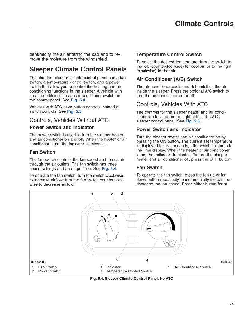
dehumidify the air entering the cab and to re-move the moisture from the windshield.
Sleeper Climate Control PanelsThe standard sleeper climate control panel has a fanswitch, a temperature control switch, and a powerswitch that allow you to control the heating and airconditioning functions in the sleeper. A vehicle withan air conditioner has an air conditioner switch onthe control panel. See Fig. 5.4.
Vehicles with ATC have button controls instead ofswitch controls. See Fig. 5.5.
Controls, Vehicles Without ATCPower Switch and IndicatorThe power switch is used to turn the sleeper heaterand air conditioner on and off. When the heater or airconditioner is on, the indicator illuminates.
Fan SwitchThe fan switch controls the fan speed and forces airthrough the air outlets. The fan switch has threespeed settings and an off position. See Fig. 5.4.
To operate the fan switch, turn the switch clockwiseto increase airflow; turn the fan switch counterclock-wise to decrease airflow.
Temperature Control SwitchTo select the desired temperature, turn the switch tothe left (counterclockwise) for cool air, or to the right(clockwise) for hot air.
Air Conditioner (A/C) SwitchThe air conditioner cools and dehumidifies the airinside the sleeper. Press the optional A/C switch toturn the air conditioner on or off.
Controls, Vehicles With ATCThe controls for the sleeper heater and air condi-tioner are located on the right side of the ATCsleeper control panel. See Fig. 5.5.
Power Switch and IndicatorTurn the sleeper heater and air conditioner on bypressing the ON button. The current set temperatureis displayed for five seconds, after which it returns tothe time display. When the heater or air conditioneris on, the indicator illuminates. To turn the sleeperheater and air conditioner off, press the OFF button.
Fan SwitchTo operate the fan switch, press the fan up or fandown button repeatedly to incrementally increase ordecrease the fan speed. Press either button for at
f610642
1 2 3
5 402/11/2003
1. Fan Switch2. Power Switch
3. Indicator4. Temperature Control Switch
5. Air Conditioner Switch
Fig. 5.4, Sleeper Climate Control Panel, No ATC
Climate Controls
5.4
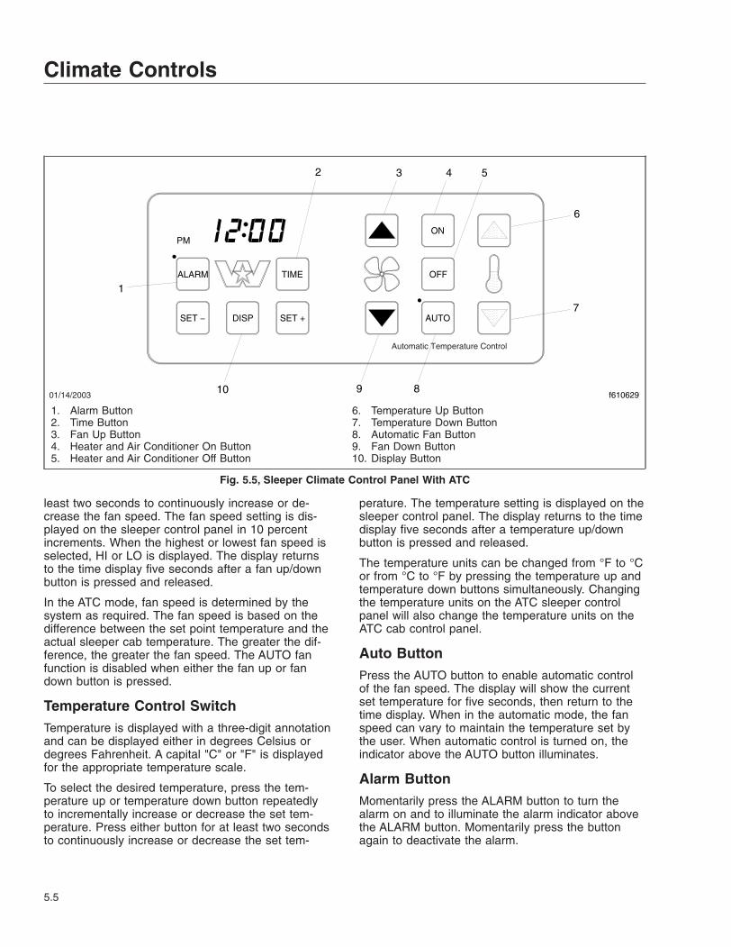
least two seconds to continuously increase or de-crease the fan speed. The fan speed setting is dis-played on the sleeper control panel in 10 percentincrements. When the highest or lowest fan speed isselected, HI or LO is displayed. The display returnsto the time display five seconds after a fan up/downbutton is pressed and released.
In the ATC mode, fan speed is determined by thesystem as required. The fan speed is based on thedifference between the set point temperature and theactual sleeper cab temperature. The greater the dif-ference, the greater the fan speed. The AUTO fanfunction is disabled when either the fan up or fandown button is pressed.
Temperature Control SwitchTemperature is displayed with a three-digit annotationand can be displayed either in degrees Celsius ordegrees Fahrenheit. A capital "C" or "F" is displayedfor the appropriate temperature scale.
To select the desired temperature, press the tem-perature up or temperature down button repeatedlyto incrementally increase or decrease the set tem-perature. Press either button for at least two secondsto continuously increase or decrease the set tem-
perature. The temperature setting is displayed on thesleeper control panel. The display returns to the timedisplay five seconds after a temperature up/downbutton is pressed and released.
The temperature units can be changed from °F to °Cor from °C to °F by pressing the temperature up andtemperature down buttons simultaneously. Changingthe temperature units on the ATC sleeper controlpanel will also change the temperature units on theATC cab control panel.
Auto ButtonPress the AUTO button to enable automatic controlof the fan speed. The display will show the currentset temperature for five seconds, then return to thetime display. When in the automatic mode, the fanspeed can vary to maintain the temperature set bythe user. When automatic control is turned on, theindicator above the AUTO button illuminates.
Alarm ButtonMomentarily press the ALARM button to turn thealarm on and to illuminate the alarm indicator abovethe ALARM button. Momentarily press the buttonagain to deactivate the alarm.
01/14/2003
Automatic Temperature Control
f610629
ALARM
SET −
TIME
SET +
ON
OFF
AUTO
PM
DISP
1
2 3 4 5
6
7
8910
1. Alarm Button2. Time Button3. Fan Up Button4. Heater and Air Conditioner On Button5. Heater and Air Conditioner Off Button
6. Temperature Up Button7. Temperature Down Button8. Automatic Fan Button9. Fan Down Button10. Display Button
Fig. 5.5, Sleeper Climate Control Panel With ATC
Climate Controls
5.5
When pressing the ALARM button, the display showsthe alarm time setting for five seconds before return-ing to the current time display. If the ALARM buttonis pressed and held down continuously for more thanone second, the alarm time setting can be viewedwithout changing the state of the alarm indicator. Ifeither the SET+ or SET– buttons are pressed simul-taneously with the ALARM button held down, thealarm time setting will increase or decrease. Whenthe ALARM button is released after changing thealarm time, the alarm will be turned on and the indi-cator will be illuminated. When the ALARM is sound-ing, press the ALARM button to turn the alarm offand to reset the alarm for the next 24-hour cycle.
To set the snooze function, press any button on thecontrol panel, except the ALARM button, when thealarm is sounding. The alarm will sound again afterseven minutes. The alarm indicator flashes when thesnooze function is set.
To cancel the snooze function, press the ALARM but-ton. This will also reset the alarm for the next 24-hour cycle.
Time ButtonThe clock controls are located on the left side of theATC sleeper control panel under the display. The dis-play will show the clock time as the default mode.
Press the TIME button to display the current time. Ifthe TIME button is held down and either the SET+ orSET– buttons are pressed simultaneously with theTIME button, the clock setting will increase or de-crease.
Display ButtonPress the DISP button to allow the display and illumi-nation of the control panel to scroll through three illu-mination levels: bright, dim, and off. If you want thealarm, time, or temperature setting to be displayedwhen the display is in the off mode, press theALARM, TIME, or temperature up/down buttons todisplay the corresponding display for five seconds.After five seconds, the display will turn off. If thealarm sounds while in the display off mode, the cur-rent time will be displayed simultaneously. The dis-play will remain on for five minutes, then turn off.
When the vehicle ignition is not powered, the sleeperclimate control panel is in a power-saving mode andthe display and illumination of the control panel will
be off. All clock functions, including the alarm, willcontinue to work internally.
Temperature Slave Mode FeatureThe temperature slave mode allows the set tempera-ture of the cab heater and air conditioner to be auto-matically tied to the sleeper heater and air condi-tioner. In this mode, the set temperature in thevehicle will be the same whether the set temperatureis changed on the cab climate control panel or thesleeper climate control panel. To enable the tempera-ture slave mode, press the SET+ and SET– buttonssimultaneously. The display will read S–ON when thetemperature slave mode is enabled.
To disable the temperature slave mode, press theSET+ and SET– buttons simultaneously. The displaywill read S–OFF indicating that the temperature slavemode is disabled. When disabled, the temperaturesfor the cab and sleeper can be changed indepen-dently for separate temperature control. If you wishto maintain a temperature in the sleeper that is differ-ent than the temperature in the front of the cab, it isrecommended that a curtain be used between thesleeper and the front of the cab.
Turning on the Sleeper Air ConditionerWhen the Cab Air Conditioner is OffThe sleeper ATC control panel can turn on the airconditioner even if the cab HVAC unit is turned offbut the engine is running. By pressing the ON button,the ATC sleeper control panel will turn on the cabunit and the bunk indicator light on the cab controlpanel will be illuminated. If cooling is needed in thesleeper, the cab HVAC unit will switch on to a lowblower fan setting and the A/C compressor clutch willengage. If cooling is no longer required in thesleeper or if heat is needed, the cab unit fan and thecompressor clutch will be turned off after a five-minute delay.
Accessory HeatersOptional accessary heaters are available from thefactory in several configurations. Familiarize yourselfwith the equipment on your specific vehicle, and fol-low the manufacturer’s operating and maintenanceinstructions.
Climate Controls
5.6
WARNINGDo not operate fuel-operated heaters in an areawhere flammable vapors, including gasoline ordiesel fumes, are present, such as at filling sta-tions and tank farms. Turn off a fuel-operatedheater and allow it shut down completely beforeentering an area where flammable gases or liq-uids are present. Heaters continue to operate forup to three minutes after being turned off.
Failure to observe these precautions could causean explosion or fire, resulting in serious propertydamage, and personal injury or death.
Climate Controls
5.7

6
Seats and RestraintsSeats, General Information . . . . . . . . . . . . . . . . . . . . . . . . . . . . . . . . . . . . . . . . . . . . . . . . . . . . . . . . . 6.1Western Star High-Back Seat . . . . . . . . . . . . . . . . . . . . . . . . . . . . . . . . . . . . . . . . . . . . . . . . . . . . . . . 6.2Bostrom Seat . . . . . . . . . . . . . . . . . . . . . . . . . . . . . . . . . . . . . . . . . . . . . . . . . . . . . . . . . . . . . . . . . . . . 6.3National Seat . . . . . . . . . . . . . . . . . . . . . . . . . . . . . . . . . . . . . . . . . . . . . . . . . . . . . . . . . . . . . . . . . . . . 6.4ABTS Seat . . . . . . . . . . . . . . . . . . . . . . . . . . . . . . . . . . . . . . . . . . . . . . . . . . . . . . . . . . . . . . . . . . . . . . 6.4Seat Belts and Tether Belts . . . . . . . . . . . . . . . . . . . . . . . . . . . . . . . . . . . . . . . . . . . . . . . . . . . . . . . . . 6.5Sleeper Compartment Restraints . . . . . . . . . . . . . . . . . . . . . . . . . . . . . . . . . . . . . . . . . . . . . . . . . . . . . 6.9
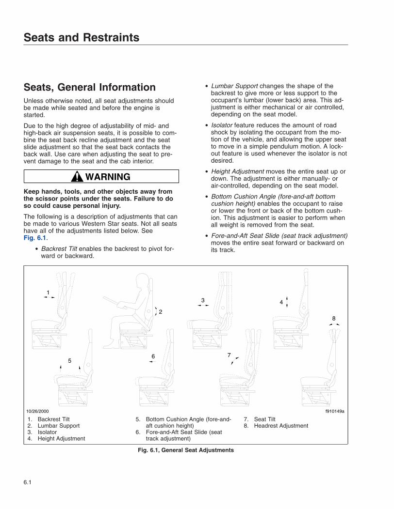
Seats, General InformationUnless otherwise noted, all seat adjustments shouldbe made while seated and before the engine isstarted.
Due to the high degree of adjustability of mid- andhigh-back air suspension seats, it is possible to com-bine the seat back recline adjustment and the seatslide adjustment so that the seat back contacts theback wall. Use care when adjusting the seat to pre-vent damage to the seat and the cab interior.
WARNINGKeep hands, tools, and other objects away fromthe scissor points under the seats. Failure to doso could cause personal injury.
The following is a description of adjustments that canbe made to various Western Star seats. Not all seatshave all of the adjustments listed below. SeeFig. 6.1.
• Backrest Tilt enables the backrest to pivot for-ward or backward.
• Lumbar Support changes the shape of thebackrest to give more or less support to theoccupant’s lumbar (lower back) area. This ad-justment is either mechanical or air controlled,depending on the seat model.
• Isolator feature reduces the amount of roadshock by isolating the occupant from the mo-tion of the vehicle, and allowing the upper seatto move in a simple pendulum motion. A lock-out feature is used whenever the isolator is notdesired.
• Height Adjustment moves the entire seat up ordown. The adjustment is either manually- orair-controlled, depending on the seat model.
• Bottom Cushion Angle (fore-and-aft bottomcushion height) enables the occupant to raiseor lower the front or back of the bottom cush-ion. This adjustment is easier to perform whenall weight is removed from the seat.
• Fore-and-Aft Seat Slide (seat track adjustment)moves the entire seat forward or backward onits track.
10/26/2000 f910149a
1
2
3 4
56 7
8
1. Backrest Tilt2. Lumbar Support3. Isolator4. Height Adjustment
5. Bottom Cushion Angle (fore-and-aft cushion height)
6. Fore-and-Aft Seat Slide (seattrack adjustment)
7. Seat Tilt8. Headrest Adjustment
Fig. 6.1, General Seat Adjustments
Seats and Restraints
6.1
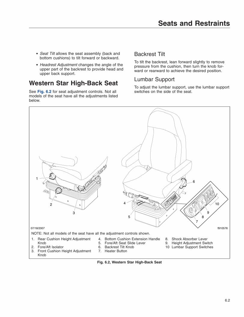
• Seat Tilt allows the seat assembly (back andbottom cushions) to tilt forward or backward.
• Headrest Adjustment changes the angle of theupper part of the backrest to provide head andupper back support.
Western Star High-Back SeatSee Fig. 6.2 for seat adjustment controls. Not allmodels of the seat have all the adjustments listedbelow.
Backrest TiltTo tilt the backrest, lean forward slightly to removepressure from the cushion, then turn the knob for-ward or rearward to achieve the desired position.
Lumbar SupportTo adjust the lumbar support, use the lumbar supportswitches on the side of the seat.
f910576
5
4
78
9
10
6
07/18/2007
1
2
3
NOTE: Not all models of the seat have all the adjustment controls shown.
1. Rear Cushion Height AdjustmentKnob
2. Fore/Aft Isolator3. Front Cushion Height Adjustment
Knob
4. Bottom Cushion Extension Handle5. Fore/Aft Seat Slide Lever6. Backrest Tilt Knob7. Heater Button
8. Shock Absorber Lever9. Height Adjustment Switch10 Lumbar Support Switches
Fig. 6.2, Western Star High-Back Seat
Seats and Restraints
6.2
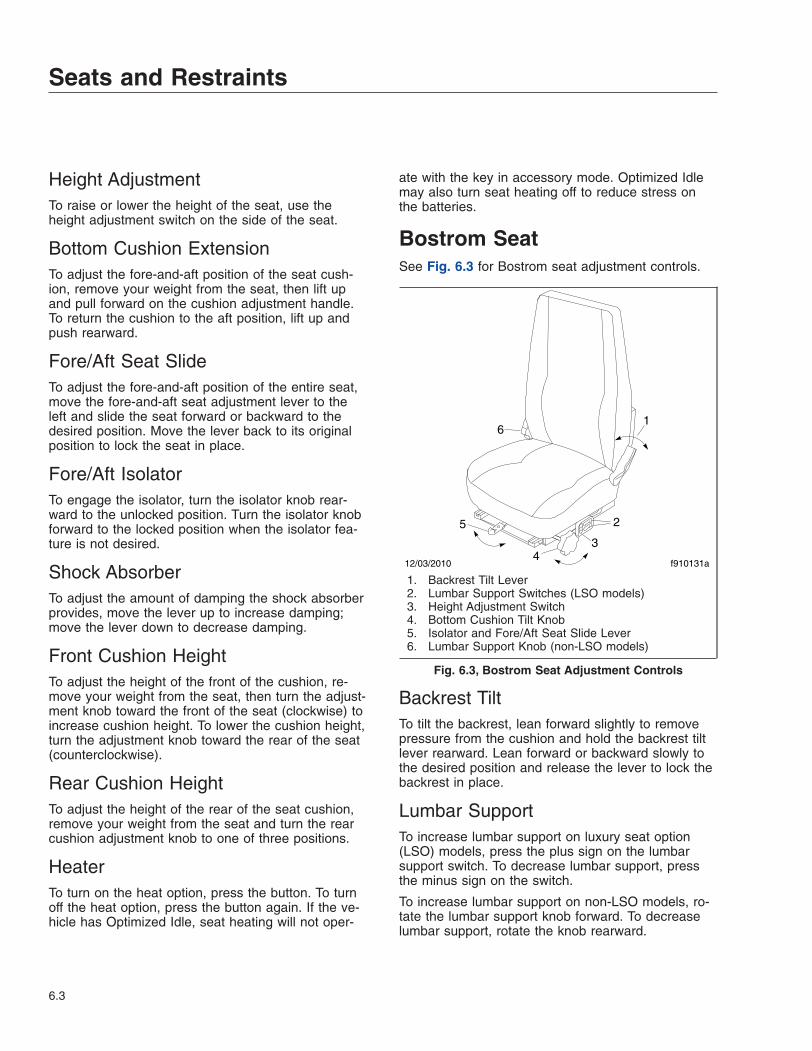
Height AdjustmentTo raise or lower the height of the seat, use theheight adjustment switch on the side of the seat.
Bottom Cushion ExtensionTo adjust the fore-and-aft position of the seat cush-ion, remove your weight from the seat, then lift upand pull forward on the cushion adjustment handle.To return the cushion to the aft position, lift up andpush rearward.
Fore/Aft Seat SlideTo adjust the fore-and-aft position of the entire seat,move the fore-and-aft seat adjustment lever to theleft and slide the seat forward or backward to thedesired position. Move the lever back to its originalposition to lock the seat in place.
Fore/Aft IsolatorTo engage the isolator, turn the isolator knob rear-ward to the unlocked position. Turn the isolator knobforward to the locked position when the isolator fea-ture is not desired.
Shock AbsorberTo adjust the amount of damping the shock absorberprovides, move the lever up to increase damping;move the lever down to decrease damping.
Front Cushion HeightTo adjust the height of the front of the cushion, re-move your weight from the seat, then turn the adjust-ment knob toward the front of the seat (clockwise) toincrease cushion height. To lower the cushion height,turn the adjustment knob toward the rear of the seat(counterclockwise).
Rear Cushion HeightTo adjust the height of the rear of the seat cushion,remove your weight from the seat and turn the rearcushion adjustment knob to one of three positions.
HeaterTo turn on the heat option, press the button. To turnoff the heat option, press the button again. If the ve-hicle has Optimized Idle, seat heating will not oper-
ate with the key in accessory mode. Optimized Idlemay also turn seat heating off to reduce stress onthe batteries.
Bostrom SeatSee Fig. 6.3 for Bostrom seat adjustment controls.
Backrest TiltTo tilt the backrest, lean forward slightly to removepressure from the cushion and hold the backrest tiltlever rearward. Lean forward or backward slowly tothe desired position and release the lever to lock thebackrest in place.
Lumbar SupportTo increase lumbar support on luxury seat option(LSO) models, press the plus sign on the lumbarsupport switch. To decrease lumbar support, pressthe minus sign on the switch.
To increase lumbar support on non-LSO models, ro-tate the lumbar support knob forward. To decreaselumbar support, rotate the knob rearward.
1
2
34
5
6
12/03/2010 f910131a
1. Backrest Tilt Lever2. Lumbar Support Switches (LSO models)3. Height Adjustment Switch4. Bottom Cushion Tilt Knob5. Isolator and Fore/Aft Seat Slide Lever6. Lumbar Support Knob (non-LSO models)
Fig. 6.3, Bostrom Seat Adjustment Controls
Seats and Restraints
6.3
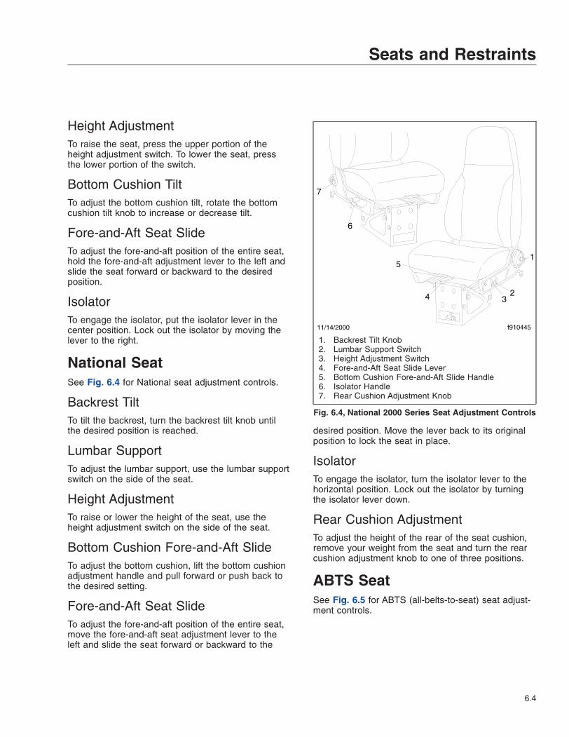
Height AdjustmentTo raise the seat, press the upper portion of theheight adjustment switch. To lower the seat, pressthe lower portion of the switch.
Bottom Cushion TiltTo adjust the bottom cushion tilt, rotate the bottomcushion tilt knob to increase or decrease tilt.
Fore-and-Aft Seat SlideTo adjust the fore-and-aft position of the entire seat,hold the fore-and-aft adjustment lever to the left andslide the seat forward or backward to the desiredposition.
IsolatorTo engage the isolator, put the isolator lever in thecenter position. Lock out the isolator by moving thelever to the right.
National SeatSee Fig. 6.4 for National seat adjustment controls.
Backrest TiltTo tilt the backrest, turn the backrest tilt knob untilthe desired position is reached.
Lumbar SupportTo adjust the lumbar support, use the lumbar supportswitch on the side of the seat.
Height AdjustmentTo raise or lower the height of the seat, use theheight adjustment switch on the side of the seat.
Bottom Cushion Fore-and-Aft SlideTo adjust the bottom cushion, lift the bottom cushionadjustment handle and pull forward or push back tothe desired setting.
Fore-and-Aft Seat SlideTo adjust the fore-and-aft position of the entire seat,move the fore-and-aft seat adjustment lever to theleft and slide the seat forward or backward to the
desired position. Move the lever back to its originalposition to lock the seat in place.
IsolatorTo engage the isolator, turn the isolator lever to thehorizontal position. Lock out the isolator by turningthe isolator lever down.
Rear Cushion AdjustmentTo adjust the height of the rear of the seat cushion,remove your weight from the seat and turn the rearcushion adjustment knob to one of three positions.
ABTS SeatSee Fig. 6.5 for ABTS (all-belts-to-seat) seat adjust-ment controls.
11/14/2000
1
234
5
f910445
6
7
1. Backrest Tilt Knob2. Lumbar Support Switch3. Height Adjustment Switch4. Fore-and-Aft Seat Slide Lever5. Bottom Cushion Fore-and-Aft Slide Handle6. Isolator Handle7. Rear Cushion Adjustment Knob
Fig. 6.4, National 2000 Series Seat Adjustment Controls
Seats and Restraints
6.4
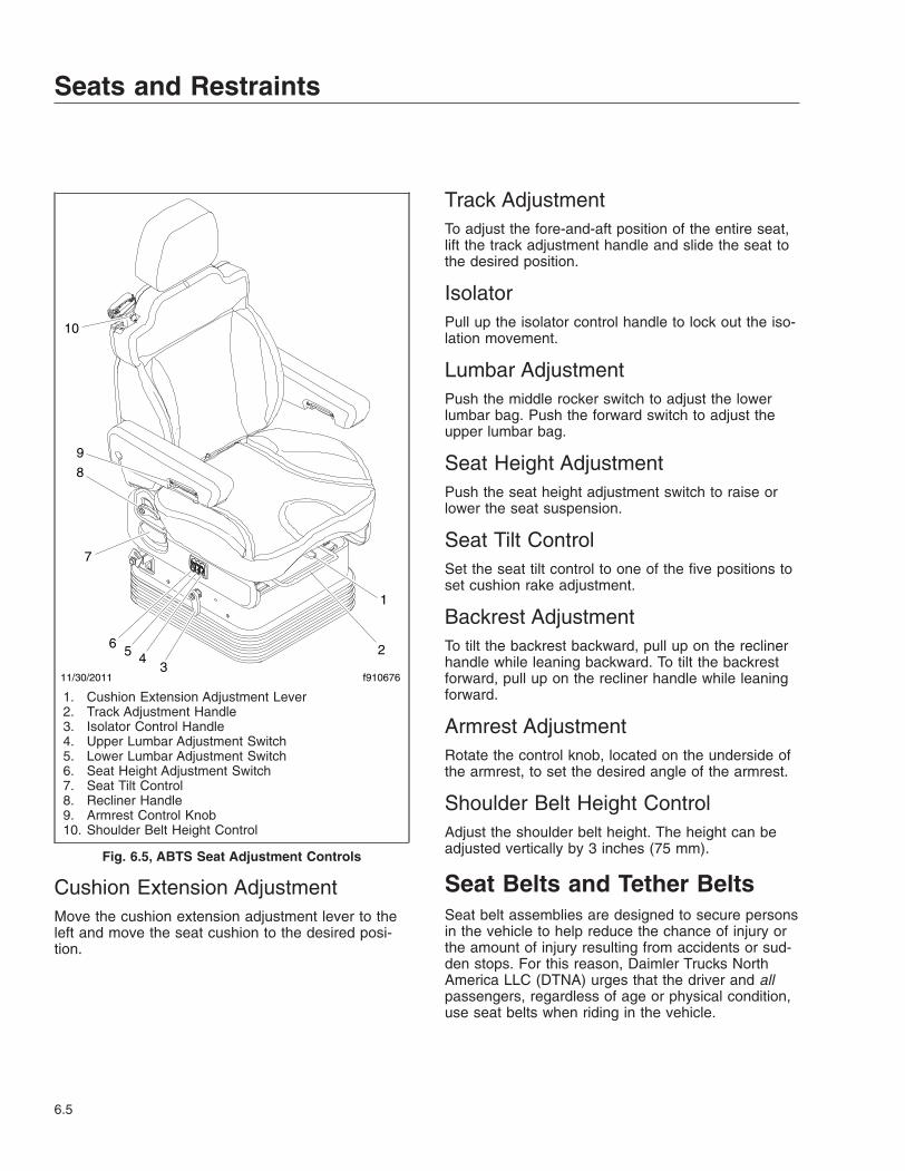
Cushion Extension AdjustmentMove the cushion extension adjustment lever to theleft and move the seat cushion to the desired posi-tion.
Track AdjustmentTo adjust the fore-and-aft position of the entire seat,lift the track adjustment handle and slide the seat tothe desired position.
IsolatorPull up the isolator control handle to lock out the iso-lation movement.
Lumbar AdjustmentPush the middle rocker switch to adjust the lowerlumbar bag. Push the forward switch to adjust theupper lumbar bag.
Seat Height AdjustmentPush the seat height adjustment switch to raise orlower the seat suspension.
Seat Tilt ControlSet the seat tilt control to one of the five positions toset cushion rake adjustment.
Backrest AdjustmentTo tilt the backrest backward, pull up on the reclinerhandle while leaning backward. To tilt the backrestforward, pull up on the recliner handle while leaningforward.
Armrest AdjustmentRotate the control knob, located on the underside ofthe armrest, to set the desired angle of the armrest.
Shoulder Belt Height ControlAdjust the shoulder belt height. The height can beadjusted vertically by 3 inches (75 mm).
Seat Belts and Tether BeltsSeat belt assemblies are designed to secure personsin the vehicle to help reduce the chance of injury orthe amount of injury resulting from accidents or sud-den stops. For this reason, Daimler Trucks NorthAmerica LLC (DTNA) urges that the driver and allpassengers, regardless of age or physical condition,use seat belts when riding in the vehicle.
11/30/2011 f910676
1
23
456
7
8
9
10
1. Cushion Extension Adjustment Lever2. Track Adjustment Handle3. Isolator Control Handle4. Upper Lumbar Adjustment Switch5. Lower Lumbar Adjustment Switch6. Seat Height Adjustment Switch7. Seat Tilt Control8. Recliner Handle9. Armrest Control Knob10. Shoulder Belt Height Control
Fig. 6.5, ABTS Seat Adjustment Controls
Seats and Restraints
6.5
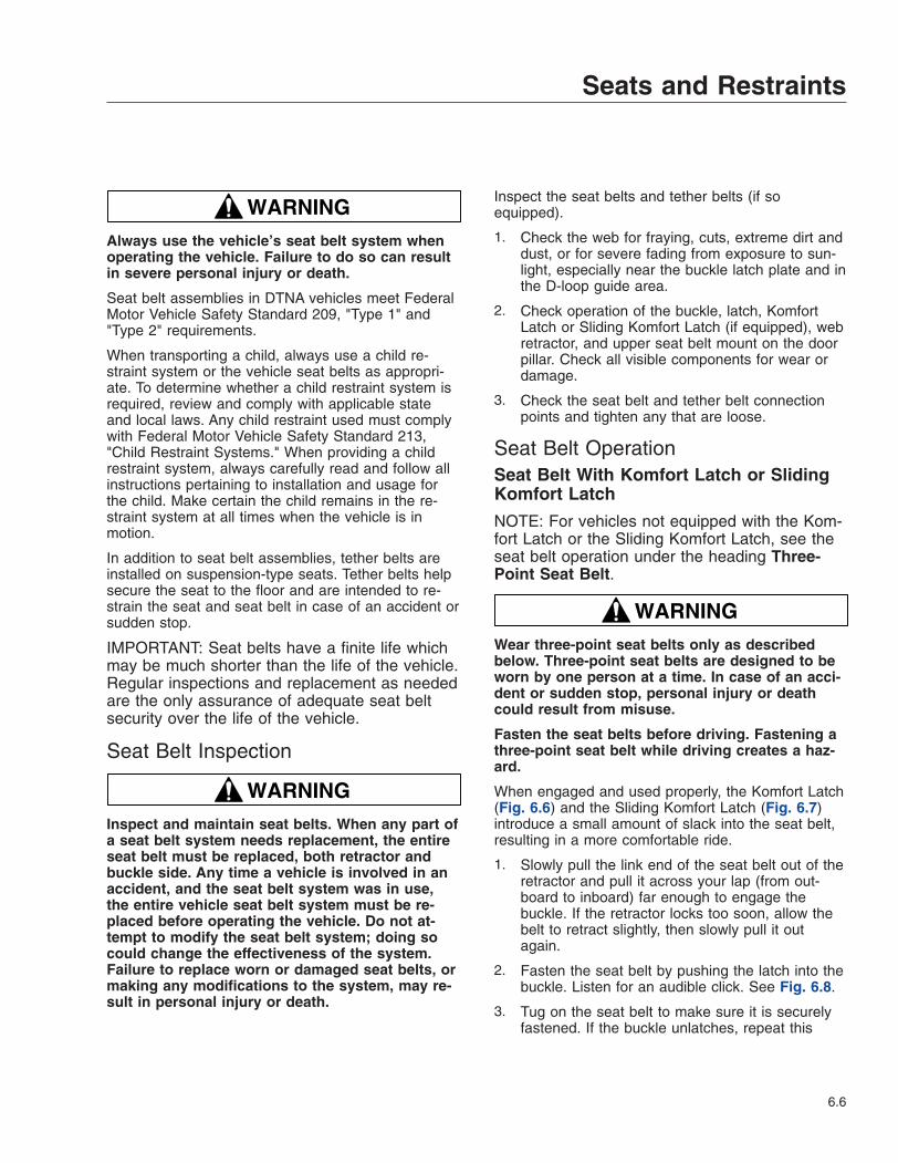
WARNINGAlways use the vehicle’s seat belt system whenoperating the vehicle. Failure to do so can resultin severe personal injury or death.
Seat belt assemblies in DTNA vehicles meet FederalMotor Vehicle Safety Standard 209, "Type 1" and"Type 2" requirements.
When transporting a child, always use a child re-straint system or the vehicle seat belts as appropri-ate. To determine whether a child restraint system isrequired, review and comply with applicable stateand local laws. Any child restraint used must complywith Federal Motor Vehicle Safety Standard 213,"Child Restraint Systems." When providing a childrestraint system, always carefully read and follow allinstructions pertaining to installation and usage forthe child. Make certain the child remains in the re-straint system at all times when the vehicle is inmotion.
In addition to seat belt assemblies, tether belts areinstalled on suspension-type seats. Tether belts helpsecure the seat to the floor and are intended to re-strain the seat and seat belt in case of an accident orsudden stop.
IMPORTANT: Seat belts have a finite life whichmay be much shorter than the life of the vehicle.Regular inspections and replacement as neededare the only assurance of adequate seat beltsecurity over the life of the vehicle.
Seat Belt Inspection
WARNINGInspect and maintain seat belts. When any part ofa seat belt system needs replacement, the entireseat belt must be replaced, both retractor andbuckle side. Any time a vehicle is involved in anaccident, and the seat belt system was in use,the entire vehicle seat belt system must be re-placed before operating the vehicle. Do not at-tempt to modify the seat belt system; doing socould change the effectiveness of the system.Failure to replace worn or damaged seat belts, ormaking any modifications to the system, may re-sult in personal injury or death.
Inspect the seat belts and tether belts (if soequipped).
1. Check the web for fraying, cuts, extreme dirt anddust, or for severe fading from exposure to sun-light, especially near the buckle latch plate and inthe D-loop guide area.
2. Check operation of the buckle, latch, KomfortLatch or Sliding Komfort Latch (if equipped), webretractor, and upper seat belt mount on the doorpillar. Check all visible components for wear ordamage.
3. Check the seat belt and tether belt connectionpoints and tighten any that are loose.
Seat Belt OperationSeat Belt With Komfort Latch or SlidingKomfort Latch
NOTE: For vehicles not equipped with the Kom-fort Latch or the Sliding Komfort Latch, see theseat belt operation under the heading Three-Point Seat Belt.
WARNINGWear three-point seat belts only as describedbelow. Three-point seat belts are designed to beworn by one person at a time. In case of an acci-dent or sudden stop, personal injury or deathcould result from misuse.
Fasten the seat belts before driving. Fastening athree-point seat belt while driving creates a haz-ard.
When engaged and used properly, the Komfort Latch(Fig. 6.6) and the Sliding Komfort Latch (Fig. 6.7)introduce a small amount of slack into the seat belt,resulting in a more comfortable ride.
1. Slowly pull the link end of the seat belt out of theretractor and pull it across your lap (from out-board to inboard) far enough to engage thebuckle. If the retractor locks too soon, allow thebelt to retract slightly, then slowly pull it outagain.
2. Fasten the seat belt by pushing the latch into thebuckle. Listen for an audible click. See Fig. 6.8.
3. Tug on the seat belt to make sure it is securelyfastened. If the buckle unlatches, repeat this
Seats and Restraints
6.6
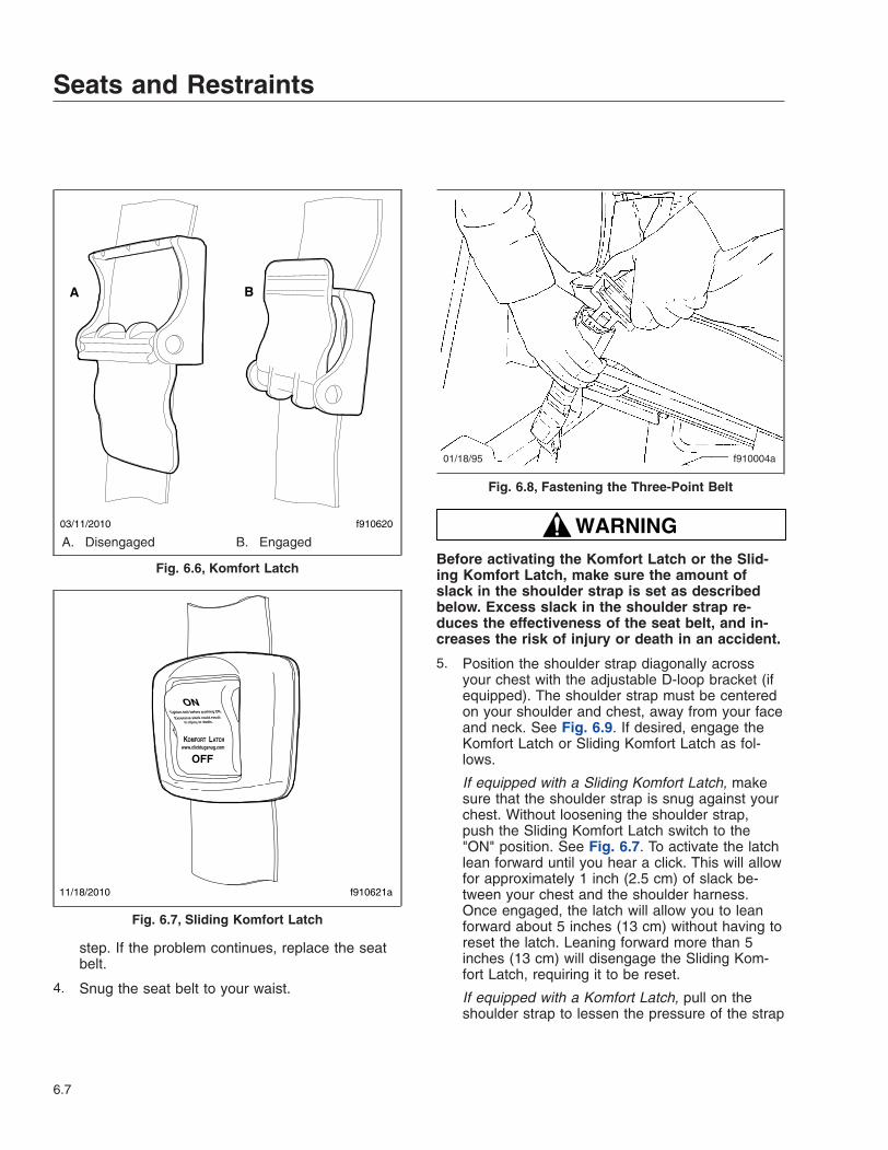
step. If the problem continues, replace the seatbelt.
4. Snug the seat belt to your waist.
WARNINGBefore activating the Komfort Latch or the Slid-ing Komfort Latch, make sure the amount ofslack in the shoulder strap is set as describedbelow. Excess slack in the shoulder strap re-duces the effectiveness of the seat belt, and in-creases the risk of injury or death in an accident.
5. Position the shoulder strap diagonally acrossyour chest with the adjustable D-loop bracket (ifequipped). The shoulder strap must be centeredon your shoulder and chest, away from your faceand neck. See Fig. 6.9. If desired, engage theKomfort Latch or Sliding Komfort Latch as fol-lows.
If equipped with a Sliding Komfort Latch, makesure that the shoulder strap is snug against yourchest. Without loosening the shoulder strap,push the Sliding Komfort Latch switch to the"ON" position. See Fig. 6.7. To activate the latchlean forward until you hear a click. This will allowfor approximately 1 inch (2.5 cm) of slack be-tween your chest and the shoulder harness.Once engaged, the latch will allow you to leanforward about 5 inches (13 cm) without having toreset the latch. Leaning forward more than 5inches (13 cm) will disengage the Sliding Kom-fort Latch, requiring it to be reset.
If equipped with a Komfort Latch, pull on theshoulder strap to lessen the pressure of the strap
03/11/2010 f910620
A B
A. Disengaged B. Engaged
Fig. 6.6, Komfort Latch
11/18/2010 f910621a
Fig. 6.7, Sliding Komfort Latch
01/18/95 f910004a
Fig. 6.8, Fastening the Three-Point Belt
Seats and Restraints
6.7
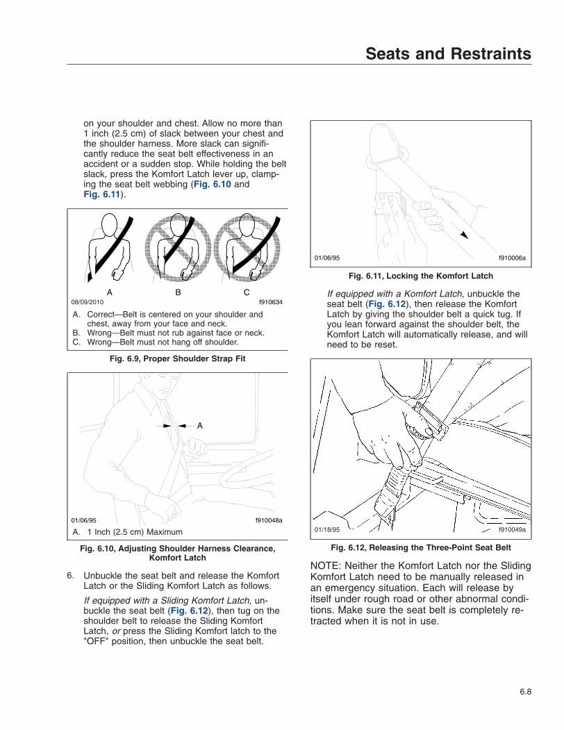
on your shoulder and chest. Allow no more than1 inch (2.5 cm) of slack between your chest andthe shoulder harness. More slack can signifi-cantly reduce the seat belt effectiveness in anaccident or a sudden stop. While holding the beltslack, press the Komfort Latch lever up, clamp-ing the seat belt webbing (Fig. 6.10 andFig. 6.11).
6. Unbuckle the seat belt and release the KomfortLatch or the Sliding Komfort Latch as follows.
If equipped with a Sliding Komfort Latch, un-buckle the seat belt (Fig. 6.12), then tug on theshoulder belt to release the Sliding KomfortLatch, or press the Sliding Komfort latch to the"OFF" position, then unbuckle the seat belt.
If equipped with a Komfort Latch, unbuckle theseat belt (Fig. 6.12), then release the KomfortLatch by giving the shoulder belt a quick tug. Ifyou lean forward against the shoulder belt, theKomfort Latch will automatically release, and willneed to be reset.
NOTE: Neither the Komfort Latch nor the SlidingKomfort Latch need to be manually released inan emergency situation. Each will release byitself under rough road or other abnormal condi-tions. Make sure the seat belt is completely re-tracted when it is not in use.
08/09/2010 f910634A B C
A. Correct—Belt is centered on your shoulder andchest, away from your face and neck.
B. Wrong—Belt must not rub against face or neck.C. Wrong—Belt must not hang off shoulder.
Fig. 6.9, Proper Shoulder Strap Fit
A
01/06/95 f910048a
A. 1 Inch (2.5 cm) Maximum
Fig. 6.10, Adjusting Shoulder Harness Clearance,Komfort Latch
01/06/95 f910006a
Fig. 6.11, Locking the Komfort Latch
01/18/95 f910049a
Fig. 6.12, Releasing the Three-Point Seat Belt
Seats and Restraints
6.8
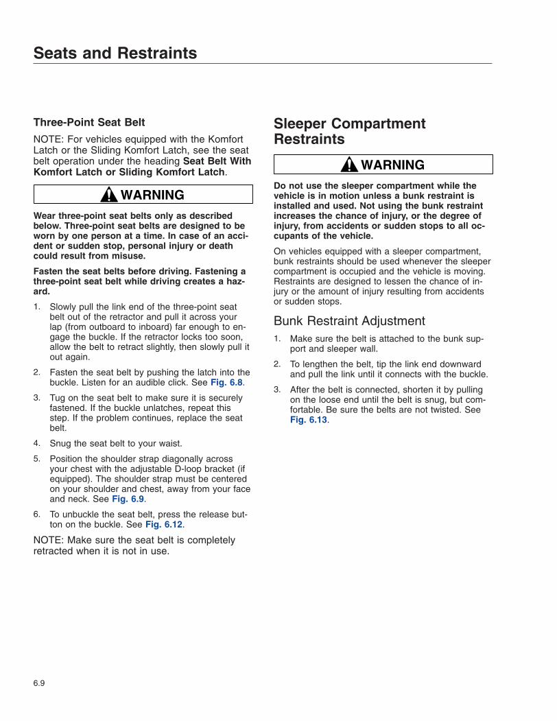
Three-Point Seat Belt
NOTE: For vehicles equipped with the KomfortLatch or the Sliding Komfort Latch, see the seatbelt operation under the heading Seat Belt WithKomfort Latch or Sliding Komfort Latch.
WARNINGWear three-point seat belts only as describedbelow. Three-point seat belts are designed to beworn by one person at a time. In case of an acci-dent or sudden stop, personal injury or deathcould result from misuse.
Fasten the seat belts before driving. Fastening athree-point seat belt while driving creates a haz-ard.
1. Slowly pull the link end of the three-point seatbelt out of the retractor and pull it across yourlap (from outboard to inboard) far enough to en-gage the buckle. If the retractor locks too soon,allow the belt to retract slightly, then slowly pull itout again.
2. Fasten the seat belt by pushing the latch into thebuckle. Listen for an audible click. See Fig. 6.8.
3. Tug on the seat belt to make sure it is securelyfastened. If the buckle unlatches, repeat thisstep. If the problem continues, replace the seatbelt.
4. Snug the seat belt to your waist.
5. Position the shoulder strap diagonally acrossyour chest with the adjustable D-loop bracket (ifequipped). The shoulder strap must be centeredon your shoulder and chest, away from your faceand neck. See Fig. 6.9.
6. To unbuckle the seat belt, press the release but-ton on the buckle. See Fig. 6.12.
NOTE: Make sure the seat belt is completelyretracted when it is not in use.
Sleeper CompartmentRestraints
WARNINGDo not use the sleeper compartment while thevehicle is in motion unless a bunk restraint isinstalled and used. Not using the bunk restraintincreases the chance of injury, or the degree ofinjury, from accidents or sudden stops to all oc-cupants of the vehicle.
On vehicles equipped with a sleeper compartment,bunk restraints should be used whenever the sleepercompartment is occupied and the vehicle is moving.Restraints are designed to lessen the chance of in-jury or the amount of injury resulting from accidentsor sudden stops.
Bunk Restraint Adjustment1. Make sure the belt is attached to the bunk sup-
port and sleeper wall.
2. To lengthen the belt, tip the link end downwardand pull the link until it connects with the buckle.
3. After the belt is connected, shorten it by pullingon the loose end until the belt is snug, but com-fortable. Be sure the belts are not twisted. SeeFig. 6.13.
Seats and Restraints
6.9
08/18/2011 f910472
1
3
A
2
A. Pull on the loose end to shorten the belt.1. Belt2. Connector
3. Release Buckle
Fig. 6.13, Bunk Restraint Adjustment
Seats and Restraints
6.10
7
Cab and Sleeper FeaturesWindows and Mirrors . . . . . . . . . . . . . . . . . . . . . . . . . . . . . . . . . . . . . . . . . . . . . . . . . . . . . . . . . . . . . . 7.1Cab Amenities . . . . . . . . . . . . . . . . . . . . . . . . . . . . . . . . . . . . . . . . . . . . . . . . . . . . . . . . . . . . . . . . . . . 7.2Sleeper Amenities . . . . . . . . . . . . . . . . . . . . . . . . . . . . . . . . . . . . . . . . . . . . . . . . . . . . . . . . . . . . . . . . . 7.3
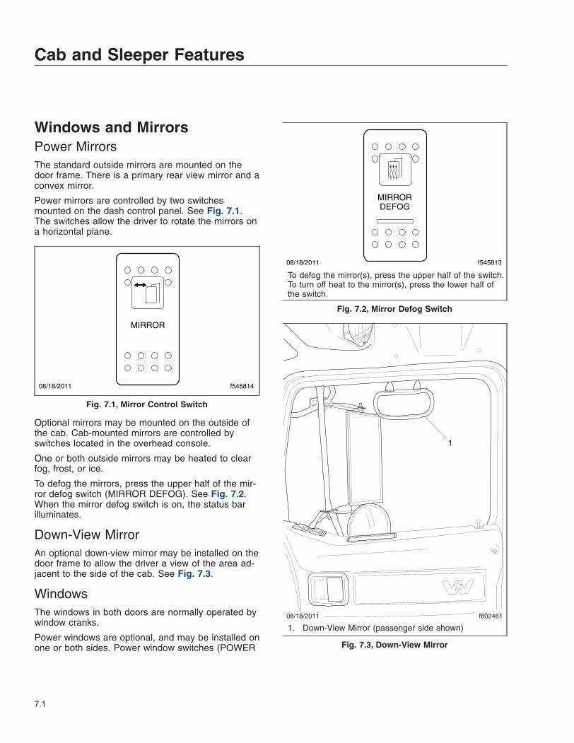
Windows and MirrorsPower MirrorsThe standard outside mirrors are mounted on thedoor frame. There is a primary rear view mirror and aconvex mirror.
Power mirrors are controlled by two switchesmounted on the dash control panel. See Fig. 7.1.The switches allow the driver to rotate the mirrors ona horizontal plane.
Optional mirrors may be mounted on the outside ofthe cab. Cab-mounted mirrors are controlled byswitches located in the overhead console.
One or both outside mirrors may be heated to clearfog, frost, or ice.
To defog the mirrors, press the upper half of the mir-ror defog switch (MIRROR DEFOG). See Fig. 7.2.When the mirror defog switch is on, the status barilluminates.
Down-View MirrorAn optional down-view mirror may be installed on thedoor frame to allow the driver a view of the area ad-jacent to the side of the cab. See Fig. 7.3.
WindowsThe windows in both doors are normally operated bywindow cranks.
Power windows are optional, and may be installed onone or both sides. Power window switches (POWER
08/18/2011 f545814
MIRROR
Fig. 7.1, Mirror Control Switch
08/18/2011 f545813
MIRRORDEFOG
To defog the mirror(s), press the upper half of the switch.To turn off heat to the mirror(s), press the lower half ofthe switch.
Fig. 7.2, Mirror Defog Switch
08/18/2011
1
f602461
1. Down-View Mirror (passenger side shown)
Fig. 7.3, Down-View Mirror
Cab and Sleeper Features
7.1
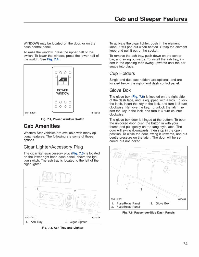
WINDOW) may be located on the door, or on thedash control panel.
To raise the window, press the upper half of theswitch. To lower the window, press the lower half ofthe switch. See Fig. 7.4.
Cab AmenitiesWestern Star vehicles are available with many op-tional features. The following are some of thoseoptions.
Cigar Lighter/Accessory PlugThe cigar lighter/accessory plug (Fig. 7.5) is locatedon the lower right-hand dash panel, above the igni-tion switch. The ash tray is located to the left of thecigar lighter.
To activate the cigar lighter, push in the elementknob. It will pop out when heated. Grasp the elementknob and pull it out of the socket.
To remove the ash tray, push down on the centerbar, and swing outwards. To install the ash tray, in-sert in the opening then swing upwards until the barsnaps into place.
Cup HoldersSingle and dual cup holders are optional, and arelocated below the right-hand dash control panel.
Glove BoxThe glove box (Fig. 7.6) is located on the right sideof the dash face, and is equipped with a lock. To lockthe latch, insert the key in the lock, and turn it ½-turnclockwise. Remove the key. To unlock the latch, in-sert the key in the lock, and turn it ½-turn counter-clockwise.
The glove box door is hinged at the bottom. To openthe unlocked door, push the button in with yourthumb and pull gently on the tang-style latch. Thedoor will swing downwards, then stop in the openposition. To close the door, swing it upwards, and putgentle pressure on the latch. The door will be se-cured, but not locked.
08/18/2011 f545812
POWERWINDOW
Fig. 7.4, Power Window Switch
03/21/2001 f610479
12
1. Ash Tray 2. Cigar Lighter
Fig. 7.5, Ash Tray and Lighter
03/21/2001 f610481
1 2
3
1. Fuse/Relay Panel2. Fuse/Relay Panel
3. Glove Box
Fig. 7.6, Passenger-Side Dash Panels
Cab and Sleeper Features
7.2
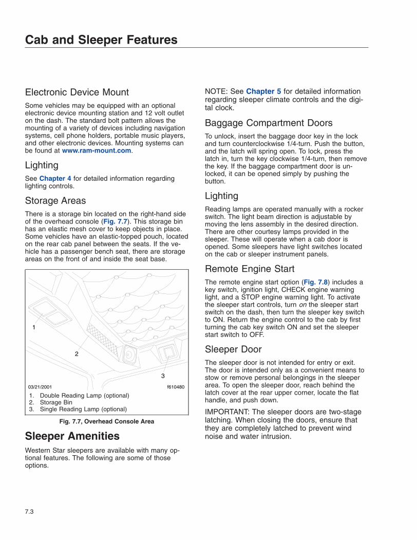
Electronic Device MountSome vehicles may be equipped with an optionalelectronic device mounting station and 12 volt outleton the dash. The standard bolt pattern allows themounting of a variety of devices including navigationsystems, cell phone holders, portable music players,and other electronic devices. Mounting systems canbe found at www.ram-mount.com.
LightingSee Chapter 4 for detailed information regardinglighting controls.
Storage AreasThere is a storage bin located on the right-hand sideof the overhead console (Fig. 7.7). This storage binhas an elastic mesh cover to keep objects in place.Some vehicles have an elastic-topped pouch, locatedon the rear cab panel between the seats. If the ve-hicle has a passenger bench seat, there are storageareas on the front of and inside the seat base.
Sleeper AmenitiesWestern Star sleepers are available with many op-tional features. The following are some of thoseoptions.
NOTE: See Chapter 5 for detailed informationregarding sleeper climate controls and the digi-tal clock.
Baggage Compartment DoorsTo unlock, insert the baggage door key in the lockand turn counterclockwise 1/4-turn. Push the button,and the latch will spring open. To lock, press thelatch in, turn the key clockwise 1/4-turn, then removethe key. If the baggage compartment door is un-locked, it can be opened simply by pushing thebutton.
LightingReading lamps are operated manually with a rockerswitch. The light beam direction is adjustable bymoving the lens assembly in the desired direction.There are other courtesy lamps provided in thesleeper. These will operate when a cab door isopened. Some sleepers have light switches locatedon the cab or sleeper instrument panels.
Remote Engine StartThe remote engine start option (Fig. 7.8) includes akey switch, ignition light, CHECK engine warninglight, and a STOP engine warning light. To activatethe sleeper start controls, turn on the sleeper startswitch on the dash, then turn the sleeper key switchto ON. Return the engine control to the cab by firstturning the cab key switch ON and set the sleeperstart switch to OFF.
Sleeper DoorThe sleeper door is not intended for entry or exit.The door is intended only as a convenient means tostow or remove personal belongings in the sleeperarea. To open the sleeper door, reach behind thelatch cover at the rear upper corner, locate the flathandle, and push down.
IMPORTANT: The sleeper doors are two-stagelatching. When closing the doors, ensure thatthey are completely latched to prevent windnoise and water intrusion.
03/21/2001 f610480
1
2
3
1. Double Reading Lamp (optional)2. Storage Bin3. Single Reading Lamp (optional)
Fig. 7.7, Overhead Console Area
Cab and Sleeper Features
7.3

Sliding Side WindowThe sliding side window is locked with an over-centertoggle lever. When unlocked, the window may beadjusted to suit.
VentThe air vent is operated using a simple, over-centerlatch. The vent will open in two directions. Push theknob firmly forward or back to open. The center posi-tion is closed.
05/14/2001 f610564
1
24
3
1. Sleeper Start2. Digital Clock
3. Climate Control Panel4. Warning Lights
Fig. 7.8, Sleeper Control Panel
Cab and Sleeper Features
7.4
8
Electrical SystemVehicle Power Distribution . . . . . . . . . . . . . . . . . . . . . . . . . . . . . . . . . . . . . . . . . . . . . . . . . . . . . . . . . . 8.1Battery Disconnect Switches . . . . . . . . . . . . . . . . . . . . . . . . . . . . . . . . . . . . . . . . . . . . . . . . . . . . . . . . 8.2Battery Access . . . . . . . . . . . . . . . . . . . . . . . . . . . . . . . . . . . . . . . . . . . . . . . . . . . . . . . . . . . . . . . . . . . 8.3

Vehicle Power DistributionPower Distribution, EPA10 and NewerThere are three standard power distribution modules(PDMs) on vehicles that are compliant with EPA10and newer regulations: the dash electrical panel, thepowertrain PDM, and the powernet distribution box(PNDB). See Fig. 8.1 for the typical locations of thepower distribution modules located in the enginecompartment.
IMPORTANT: The covers on the underhoodPDM units must be in place to protect againstwater splash and dust intrusion.
The powertrain PDM houses many of the fuses andrelays for the engine, transmission, and aftertreat-ment system (ATS). There is a label on the cover ofthe powertrain PDM identifying the fuses and relays.
The PNDB houses up to three MIDI fuses and fourATO fuses. A label on the cover of the PNDB identi-fies the fuses.
08/17/2011
1
2
3
f545811
1. MEGA Fuse Location (EPA07 and earlier vehicles)2. Powertrain PDM (EPA10 and newer vehicles)3. PNDB (EPA10 and newer vehicles)
Fig. 8.1, PDM Locations
Electrical System
8.1

Vehicles may also be equipped with a secondaryPNDB. The secondary PNDB sources power to anyof the following:
• fleet management communications
• trailer end-of-frame connection
• shore power inverter
• bodybuilder PDM (housing any fuses and re-lays necessary for customer-installed truckbody equipment)
The dash electrical panel is located inboard of thepassenger-side glove box. Access to the panel isachieved by removing the four screws located ineach corner of the panel cover. See Fig. 8.2. A decalshowing the layout of the fuses, breakers, and relaysis on the back of the panel cover. See Fig. 8.3.
Pre-EPA10 Power DistributionVehicles that are not compliant with EPA10 or newerregulations have one PDM in the engine compart-ment (see Fig. 8.1) and two MEGA fuses in the dashelectrical panel.
The dash electrical panel is located inboard of thepassenger-side glove box. Access to the panel isachieved by removing the four screws located ineach corner of the panel. See Fig. 8.2. A decal,showing the layout of the fuses, breakers and relays,is on the back of the panel cover. See Fig. 8.3.
Battery Disconnect SwitchesYour Western Star vehicle may be equipped with acab load disconnect switch (CLDS) or a battery isola-tion switch.
Cab Load Disconnect Switch, EPA10and NewerThe optional CLDS (Fig. 8.4) is used to minimizedraw on the battery, and should be turned off whenthe vehicle is parked for an extended period of time.
When the CLDS is set to OFF, it signals the PNDB todisconnect battery power to the circuits powered bythe MIDI fuses.
The CLDS is mounted on the cab floor outboard ofthe driver’s seat, on the lower driver-side dash panel,or near the battery box.
IMPORTANT: The ignition should be turned OFFbefore using the CLDS.
Pre-EPA10 Battery Isolation SwitchThe optional battery isolation switch (see Fig. 8.5) islocated on the cab floor outboard of the driver’s seat,on a bracket near the driver-side kick panel belowthe dash, or near the battery box. The battery isola-tion switch disconnects the power to most cab cir-cuits and engine power wiring. Use it whenever the
11/13/2001 f543947
2
1
1. Electrical Panel Cover2. Mounting Screws
Fig. 8.2, Dash Panel
11/13/2001 f5439491 2
1. Decal Option Panel2. Decal Main Panel
Fig. 8.3, Electrical Panel Decals
Electrical System
8.2
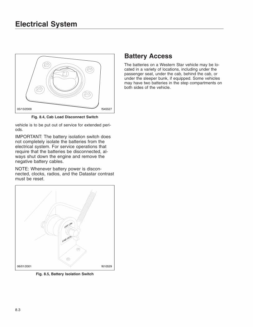
vehicle is to be put out of service for extended peri-ods.
IMPORTANT: The battery isolation switch doesnot completely isolate the batteries from theelectrical system. For service operations thatrequire that the batteries be disconnected, al-ways shut down the engine and remove thenegative battery cables.
NOTE: Whenever battery power is discon-nected, clocks, radios, and the Datastar contrastmust be reset.
Battery AccessThe batteries on a Western Star vehicle may be lo-cated in a variety of locations, including under thepassenger seat, under the cab, behind the cab, orunder the sleeper bunk, if equipped. Some vehiclesmay have two batteries in the step compartments onboth sides of the vehicle.
05/13/2009 f545527
Fig. 8.4, Cab Load Disconnect Switch
06/01/2001 f610529
Fig. 8.5, Battery Isolation Switch
Electrical System
8.3
9
Engine Starting, Operation,and Shutdown
Engine Starting . . . . . . . . . . . . . . . . . . . . . . . . . . . . . . . . . . . . . . . . . . . . . . . . . . . . . . . . . . . . . . . . . . . 9.1Engine Operation . . . . . . . . . . . . . . . . . . . . . . . . . . . . . . . . . . . . . . . . . . . . . . . . . . . . . . . . . . . . . . . . . 9.1Engine Shutdown . . . . . . . . . . . . . . . . . . . . . . . . . . . . . . . . . . . . . . . . . . . . . . . . . . . . . . . . . . . . . . . . . 9.3Engine Cooling . . . . . . . . . . . . . . . . . . . . . . . . . . . . . . . . . . . . . . . . . . . . . . . . . . . . . . . . . . . . . . . . . . . 9.3
Engine StartingThis engine chapter is to serve as a guide for bestpractices only. Each engine model may have operat-ing characteristics that are unique to that particularengine, and will be documented in the engine manu-facturer’s literature. Always refer to specific instruc-tions and recommendations from the engine manu-facturer.
NOTE: Before starting the engine, read Chap-ter 3 for detailed information on how to read theinstruments and see Chapter 4 for detailed in-formation on how to operate the controls. Readthe engine manufacturer’s operating instructionsbefore starting the engine.
WARNINGNever pour fuel or other flammable liquid into theair inlet opening in the air intake in an attempt tostart the vehicle. This could result in a flash firecausing serious personal injury or propertydamage.
1. Before engine start-up, complete the engine pre-trip inspections in Chapter 23.
2. Set the parking brake.
3. Place the transmission in neutral. On vehicleswith manual transmissions, fully depress theclutch pedal.
4. Turn the ignition switch to the ON position. Thebuzzer will sound for three seconds.
During cold conditions, the WAIT TO STARTlamp may illuminate. Wait until the lamp goes outbefore turning the ignition key to START.
NOTE: The length of time the WAIT TO STARTlamp remains illuminated depends on the ambi-ent temperature. The lower the ambient tem-perature, the longer the lamp will be illuminated.
NOTE: The engine electronics supply the cor-rect amount of fuel for starting the engine. Ac-celerator pedal pressure is unnecessary andcould interfere with engine starting.
5. Turn the ignition key to the START position. Re-lease the key the moment the engine starts.
6. Apply load gradually during the warm-up period.
NOTICEIf the oil pressure gauge indicates no oil pres-sure, shut down the engine within approximatelyten seconds to avoid engine damage.
7. Check the oil pressure gauge for any drop in lu-bricating oil pressure or mechanical malfunctionin the lubricating oil system.
Cold-Weather StartingSee the engine manufacturer’s operation manual forstarting aids that are approved for specific engines.
Starting After Extended ShutdownBefore engine start-up, complete the engine pretripinspections in Chapter 23.
NOTICEFailure to eliminate water-diluted lubricating oilmay lead to serious engine damage at startup.
An engine in storage for an extended period of time(over winter, for example) may accumulate water inthe oil pan through normal condensation of moistureon the internal surfaces of the engine. Oil diluted bywater cannot provide adequate bearing protection atstart-up. For this reason, change the engine oil andfilters after extended storage.
Engine OperationSafety and EnvironmentalConsiderationsAll engines on Western Star vehicles comply with therequirements of the Federal (U.S.) Clean Air Act.Once an engine is placed in service, the responsibil-ity for meeting both state and local regulations is withthe owner/operator.
IMPORTANT: Depending upon local jurisdic-tional emissions guidelines, vehicles that aredomiciled outside of the U.S. and Canada maynot have engines and/or emissions aftertreat-ment systems that are compliant with EPA07,EPA10, GHG14, or GHG17 regulations.
Engine Starting, Operation, and Shutdown
9.1
NOTICEIt is extremely important that the following guide-lines be followed for engines that comply withEPA07 or newer regulations, or damage mayoccur to the aftertreatment device, and the war-ranty may be compromised.
• Use ultralow-sulfur diesel with 15 ppm sul-fur content or less.
• Do not use fuel blended with used enginelube oil or kerosene.
• Use only engine lube oil with a sulfated ashlevel less than 1.0 wt%; currently referredto as CJ-4 oil.
Adequate maintenance of the engine and the dieselparticulate filter (DPF) are the responsibility of theowner/operator, and are essential to keep the emis-sion levels low. Good operating practices, regularmaintenance, and correct adjustments are factorsthat will help keep emissions within the regulations.
The driver should be familiar with the vehicle warningsystem in order to bring the vehicle to a safe stop ifthe engine malfunctions. If the driver doesn’t under-stand how the warning system works, an engineshutdown could occur, causing a safety hazard. SeeChapter 10 for more information.
Engine Break-InEach engine must pass a full-load operating test ona dynamometer before shipment, thereby eliminatingthe need for a break-in. Before running the enginefor the first time, follow the instructions in the enginemanufacturer’s operation manual specific to yourengine.
Normal Operation
WARNINGDo not operate the engine in an area where flam-mable vapors such as gasoline or diesel fumesare present. Shut off the engine when in an areawhere flammable liquids or gases are beinghandled. Failure to observe these precautionscould result in serious injury or death.
Every engine has an operating range in which it per-forms most efficiently. The operating range extends
from maximum torque rpm at the low end, to enginerated speed at the high end. Most engines deliverbest fuel economy when operated in the low- andmid-speed segments of the efficiency range and pro-duce maximum horsepower at rated speed, which isalso the recommended maximum speed of the en-gine. For further engine-specific information, refer tothe engine manufacturer’s operation manual.
Prolonged idling of engines is not recommended, andis illegal in some states. Idling produces sulfuric acid,that is absorbed by the lubricating oil, and eats intobearings, rings, valve stems, and engine surfaces. Ifyou must idle the engine for cab heat or cooling, usethe high idle function of the cruise control switches.An idle speed of 900 rpm should be enough to pro-vide cab heat in ambient temperatures that areabove freezing.
If the engine is programmed with the idle shutdowntimer, ninety seconds before the preset shutdowntime, the CHECK engine light will begin to flash at arapid rate. If the position of the clutch pedal or ser-vice brake changes during this final ninety secondsthe idle shutdown timer will be disabled until reset.
Cold-Weather OperationSatisfactory performance of a diesel engine operatingin low ambient temperatures requires modification ofthe engine, surrounding equipment, operating prac-tices, and maintenance procedures. The lower thetemperature, the greater the amount of modificationrequired. For service products approved for use incold weather for your engine, see the engine manu-facturer’s engine operation manual.
If satisfactory engine temperature is not maintained,maintenance costs will increase due to greater en-gine wear. If the engine coolant gets too cold, rawfuel will wash the lubricating oil off the cylinder wallsand dilute the crankcase oil, causing all moving partsof the engine to suffer from poor lubrication.
If the engine is in good mechanical condition and theprecautions necessary for cold-weather operation aretaken, ordinary cold weather will not cause difficultyin starting or loss of efficiency.
The following points are important to observe whenoperating in cold weather:
• Check for cracks in the batteries, for corrosionof the terminals, and for tightness of the cableclamps at the terminals.
Engine Starting, Operation, and Shutdown
9.2

• Charge the batteries to full capacity. Replacedamaged batteries.
• If equipped, turn off the load disconnect switchafter the engine is shut down, to prevent bat-tery discharge.
• Have the alternator output checked at an au-thorized service provider.
• Check the condition and tension of the drivebelts.
• Refer to the engine manufacturer’s operationmanual for recommended heaters, low-viscosity lubricating oils, winter-grade fuels,and approved coolants.
NOTICEFor Detroit engines (EPA07 and newer), use of awinterfront is not recommended, as it can causefalse fault codes with the engine and aftertreat-ment system, and possible emission componentfailures.
If using a winterfront, leave at least 25% of the grilleopening exposed in sectioned stripes that run per-pendicular to the charge-air-cooler tube-flow direc-tion. This assures even cooling across each tube,and reduces header-to-tube stress, and possiblechance of component failure. For engine-specificguidelines, see below:
Cummins and Mercedes-Benz engines: A winterfrontmay be used to improve cab heating while idling, andonly when the ambient temperature remains below10°F (-12°C).
Detroit engines (EPA07 and newer): Use of a winter-front is not recommended. Using a winterfront cancause excessive fan run time, increased fuel con-sumption, and failure of the DEF system heaters tooperate correctly, resulting in fault codes, poor per-formance, and power reduction. A winterfront shouldonly be used temporarily in the following situations:
• to improve cab heating while idling in an ex-tremely cold ambient temperature;
• when the ambient temperature remains below-22°F (-30°C) and the engine is unable tomaintain a running coolant temperature of175°F (80°C) during normal over-the-road op-eration.
Engine Shutdown1. With the vehicle stopped, set the parking brake
and place the transmission in neutral.
NOTICEIdle the engine one to two minutes before shut-ting it down. After hard operation, shutting downthe engine without idling may cause damage tothe turbocharger.
2. Allow the engine to idle one to two minutes be-fore shutting it down.
NOTICEExcept in an emergency, do not shut down theengine when the coolant temperature is above194°F (90°C). To do so could damage the engine.
3. Turn off the ignition switch and shut down theengine.
Engine CoolingThe cooling system used on all Western Star ve-hicles is a pressure type system. This raises thecoolant boiling point, permitting higher operating tem-peratures. The coolant supplied in your vehicle willbe a 50/50 mix of antifreeze and water, giving protec-tion down to –35°F (–37°C). It is recommended thatan antifreeze mixture be used at all times, as, in ad-dition to providing frost protection, it is a more effec-tive coolant, and has a higher boiling point than tapwater.
Over-concentration of antifreeze or coolant condi-tioner can cause silicate to precipitate out of thecoolant, forming silica gel on cooling system heattransfer surfaces (fuel coolers, oil coolers, radiators,and heater cores), resulting in reduced coolant flowand overheating.
Hard water (with high levels of calcium and magne-sium ions) encourages formation of silica gel. Do notuse softened water as the salt used to artificiallysoften it is corrosive. Most engine manufacturers pre-fer the use of distilled or de-ionized water to reducethe potential and severity of silicate dropouts.
Never exceed a 60/40 antifreeze-to-water ratio. If thelevel is low, add a 50/50 antifreeze solution to main-tain solution concentrations. Note that checking the
Engine Starting, Operation, and Shutdown
9.3

engine coolant level is part of the pretrip inspection.See Chapter 23 for more information.
Engine Starting, Operation, and Shutdown
9.4

10
Optional Engine SystemsEngine Protection—Warning and Shutdown . . . . . . . . . . . . . . . . . . . . . . . . . . . . . . . . . . . . . . . . . . . 10.1Engine Idle Limiting . . . . . . . . . . . . . . . . . . . . . . . . . . . . . . . . . . . . . . . . . . . . . . . . . . . . . . . . . . . . . . 10.1Cruise Control . . . . . . . . . . . . . . . . . . . . . . . . . . . . . . . . . . . . . . . . . . . . . . . . . . . . . . . . . . . . . . . . . . . 10.2Auxiliary Braking Applications . . . . . . . . . . . . . . . . . . . . . . . . . . . . . . . . . . . . . . . . . . . . . . . . . . . . . . 10.3Power Takeoff (PTO) Governor . . . . . . . . . . . . . . . . . . . . . . . . . . . . . . . . . . . . . . . . . . . . . . . . . . . . . 10.5
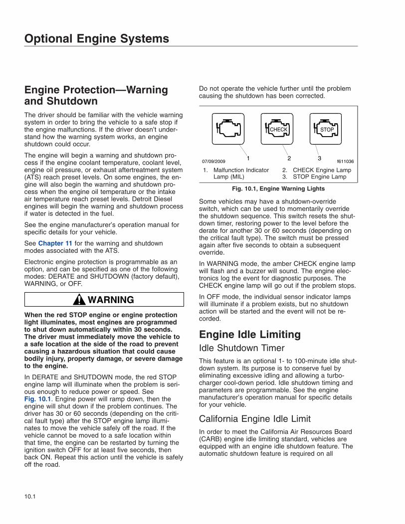
Engine Protection—Warningand ShutdownThe driver should be familiar with the vehicle warningsystem in order to bring the vehicle to a safe stop ifthe engine malfunctions. If the driver doesn’t under-stand how the warning system works, an engineshutdown could occur.
The engine will begin a warning and shutdown pro-cess if the engine coolant temperature, coolant level,engine oil pressure, or exhaust aftertreatment system(ATS) reach preset levels. On some engines, the en-gine will also begin the warning and shutdown pro-cess when the engine oil temperature or the intakeair temperature reach preset levels. Detroit Dieselengines will begin the warning and shutdown processif water is detected in the fuel.
See the engine manufacturer’s operation manual forspecific details for your vehicle.
See Chapter 11 for the warning and shutdownmodes associated with the ATS.
Electronic engine protection is programmable as anoption, and can be specified as one of the followingmodes: DERATE and SHUTDOWN (factory default),WARNING, or OFF.
WARNINGWhen the red STOP engine or engine protectionlight illuminates, most engines are programmedto shut down automatically within 30 seconds.The driver must immediately move the vehicle toa safe location at the side of the road to preventcausing a hazardous situation that could causebodily injury, property damage, or severe damageto the engine.
In DERATE and SHUTDOWN mode, the red STOPengine lamp will illuminate when the problem is seri-ous enough to reduce power or speed. SeeFig. 10.1. Engine power will ramp down, then theengine will shut down if the problem continues. Thedriver has 30 or 60 seconds (depending on the criti-cal fault type) after the STOP engine lamp illumi-nates to move the vehicle safely off the road. If thevehicle cannot be moved to a safe location withinthat time, the engine can be restarted by turning theignition switch OFF for at least five seconds, thenback ON. Repeat this action until the vehicle is safelyoff the road.
Do not operate the vehicle further until the problemcausing the shutdown has been corrected.
Some vehicles may have a shutdown-overrideswitch, which can be used to momentarily overridethe shutdown sequence. This switch resets the shut-down timer, restoring power to the level before thederate for another 30 or 60 seconds (depending onthe critical fault type). The switch must be pressedagain after five seconds to obtain a subsequentoverride.
In WARNING mode, the amber CHECK engine lampwill flash and a buzzer will sound. The engine elec-tronics log the event for diagnostic purposes. TheCHECK engine lamp will go out if the problem stops.
In OFF mode, the individual sensor indicator lampswill illuminate if a problem exists, but no shutdownaction will be started and the event will not be re-corded.
Engine Idle LimitingIdle Shutdown TimerThis feature is an optional 1- to 100-minute idle shut-down system. Its purpose is to conserve fuel byeliminating excessive idling and allowing a turbo-charger cool-down period. Idle shutdown timing andparameters are programmable. See the enginemanufacturer’s operation manual for specific detailsfor your vehicle.
California Engine Idle LimitIn order to meet the California Air Resources Board(CARB) engine idle limiting standard, vehicles areequipped with an engine idle shutdown feature. Theautomatic shutdown feature is required on all
07/09/2009 f6110361 2 3
CHECK STOP
1. Malfunction IndicatorLamp (MIL)
2. CHECK Engine Lamp3. STOP Engine Lamp
Fig. 10.1, Engine Warning Lights
Optional Engine Systems
10.1
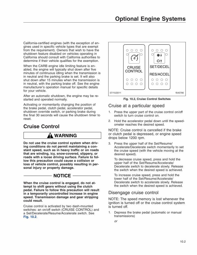
California-certified engines (with the exception of en-gines used in specific vehicle types that are exemptfrom the requirement). Owners that wish to have theshutdown feature disabled on vehicles operating inCalifornia should consult with California authorities todetermine if their vehicle qualifies for the exemption.
When the CARB engine idle limiting feature is en-abled, the engine will typically shut down after fiveminutes of continuous idling when the transmission isin neutral and the parking brake is set. It will alsoshut down after 15 minutes when the transmission isin neutral, with the parking brake off. See the enginemanufacturer’s operation manual for specific detailsfor your vehicle.
After an automatic shutdown, the engine may be re-started and operated normally.
Activating or momentarily changing the position ofthe brake pedal, clutch pedal, accelerator pedal,shutdown override switch, or parking brake duringthe final 30 seconds will cause the shutdown timer toreset.
Cruise Control
WARNINGDo not use the cruise control system when driv-ing conditions do not permit maintaining a con-stant speed, such as in heavy traffic or on roadsthat are winding, icy, snow-covered, slippery, orroads with a loose driving surface. Failure to fol-low this precaution could cause a collision orloss of vehicle control, possibly resulting in per-sonal injury or property damage.
NOTICEWhen the cruise control is engaged, do not at-tempt to shift gears without using the clutchpedal. Failure to follow this precaution will resultin a temporarily uncontrolled increase in enginespeed. Transmission damage and gear strippingcould result.
Cruise control is activated by two dash-mountedswitches: an on/off switch (CRUISE CONTROL) anda Set/Decelerate/Resume/Accelerate switch. SeeFig. 10.2.
Cruise at a particular speed1. Press the upper part of the cruise control on/off
switch to turn cruise control on.
2. Hold the accelerator pedal down until the speed-ometer reaches the desired speed.
NOTE: Cruise control is cancelled if the brakeor clutch pedal is depressed, or engine speeddrops below 1200 rpm.
3. Press the upper half of the Set/Resume/Accelerate/Decelerate switch momentarily to setthe cruise speed (with the vehicle moving at thedesired speed).
To decrease cruise speed, press and hold theupper half of the Set/Resume/Accelerate/Decelerate switch to decelerate slowly. Releasethe switch when the desired speed is achieved.
To increase cruise speed, press and hold thelower half of the Set/Resume/Accelerate/Decelerate switch to accelerate slowly. Releasethe switch when the desired speed is achieved.
Disengage cruise controlNOTE: The speed memory is lost whenever theignition is turned off or the cruise control systemis turned off.
1. Depress the brake pedal (automatic or manualtransmissions)
or
07/15/2011 f545790
CRUISECONTROL
SET/DECEL
RES/ACCEL
Fig. 10.2, Cruise Control Switches
Optional Engine Systems
10.2
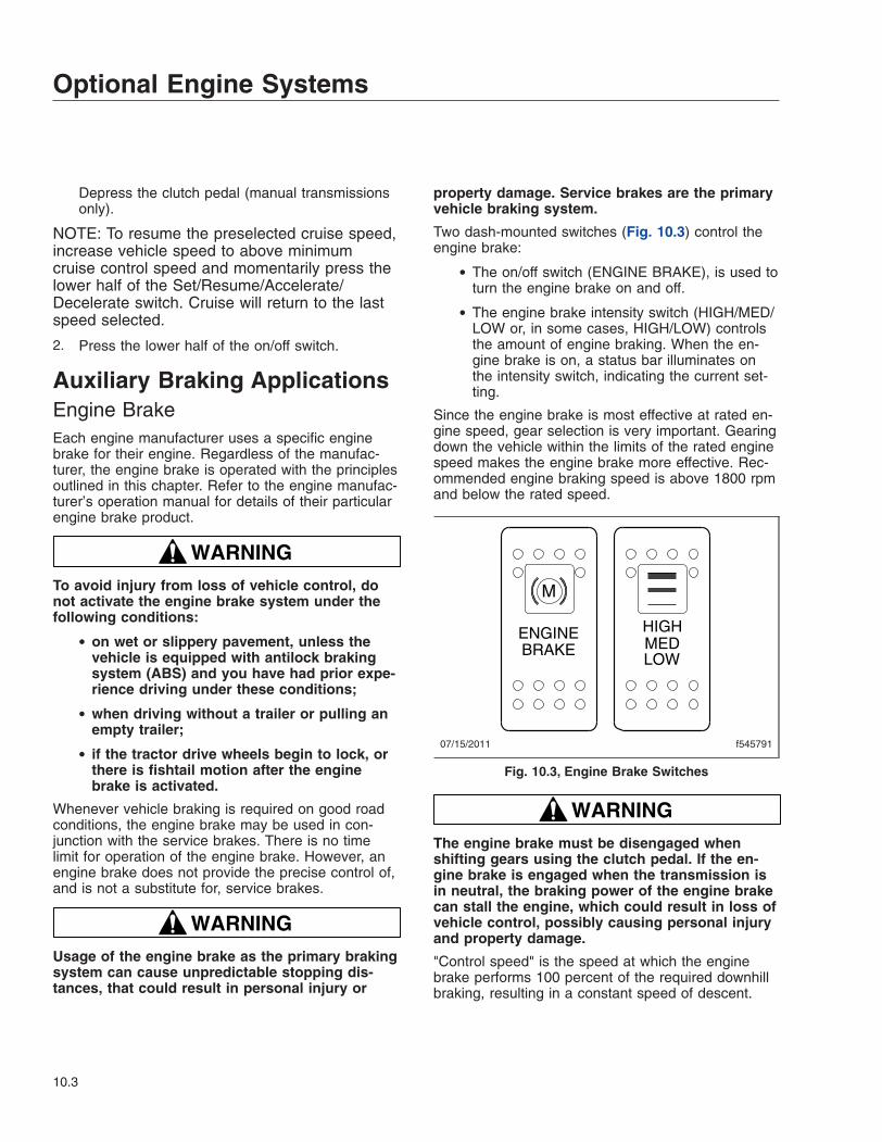
Depress the clutch pedal (manual transmissionsonly).
NOTE: To resume the preselected cruise speed,increase vehicle speed to above minimumcruise control speed and momentarily press thelower half of the Set/Resume/Accelerate/Decelerate switch. Cruise will return to the lastspeed selected.
2. Press the lower half of the on/off switch.
Auxiliary Braking ApplicationsEngine BrakeEach engine manufacturer uses a specific enginebrake for their engine. Regardless of the manufac-turer, the engine brake is operated with the principlesoutlined in this chapter. Refer to the engine manufac-turer’s operation manual for details of their particularengine brake product.
WARNINGTo avoid injury from loss of vehicle control, donot activate the engine brake system under thefollowing conditions:
• on wet or slippery pavement, unless thevehicle is equipped with antilock brakingsystem (ABS) and you have had prior expe-rience driving under these conditions;
• when driving without a trailer or pulling anempty trailer;
• if the tractor drive wheels begin to lock, orthere is fishtail motion after the enginebrake is activated.
Whenever vehicle braking is required on good roadconditions, the engine brake may be used in con-junction with the service brakes. There is no timelimit for operation of the engine brake. However, anengine brake does not provide the precise control of,and is not a substitute for, service brakes.
WARNINGUsage of the engine brake as the primary brakingsystem can cause unpredictable stopping dis-tances, that could result in personal injury or
property damage. Service brakes are the primaryvehicle braking system.
Two dash-mounted switches (Fig. 10.3) control theengine brake:
• The on/off switch (ENGINE BRAKE), is used toturn the engine brake on and off.
• The engine brake intensity switch (HIGH/MED/LOW or, in some cases, HIGH/LOW) controlsthe amount of engine braking. When the en-gine brake is on, a status bar illuminates onthe intensity switch, indicating the current set-ting.
Since the engine brake is most effective at rated en-gine speed, gear selection is very important. Gearingdown the vehicle within the limits of the rated enginespeed makes the engine brake more effective. Rec-ommended engine braking speed is above 1800 rpmand below the rated speed.
WARNINGThe engine brake must be disengaged whenshifting gears using the clutch pedal. If the en-gine brake is engaged when the transmission isin neutral, the braking power of the engine brakecan stall the engine, which could result in loss ofvehicle control, possibly causing personal injuryand property damage.
"Control speed" is the speed at which the enginebrake performs 100 percent of the required downhillbraking, resulting in a constant speed of descent.
07/15/2011 f545791
ENGINEBRAKE
M
HIGHMEDLOW
Fig. 10.3, Engine Brake Switches
Optional Engine Systems
10.3
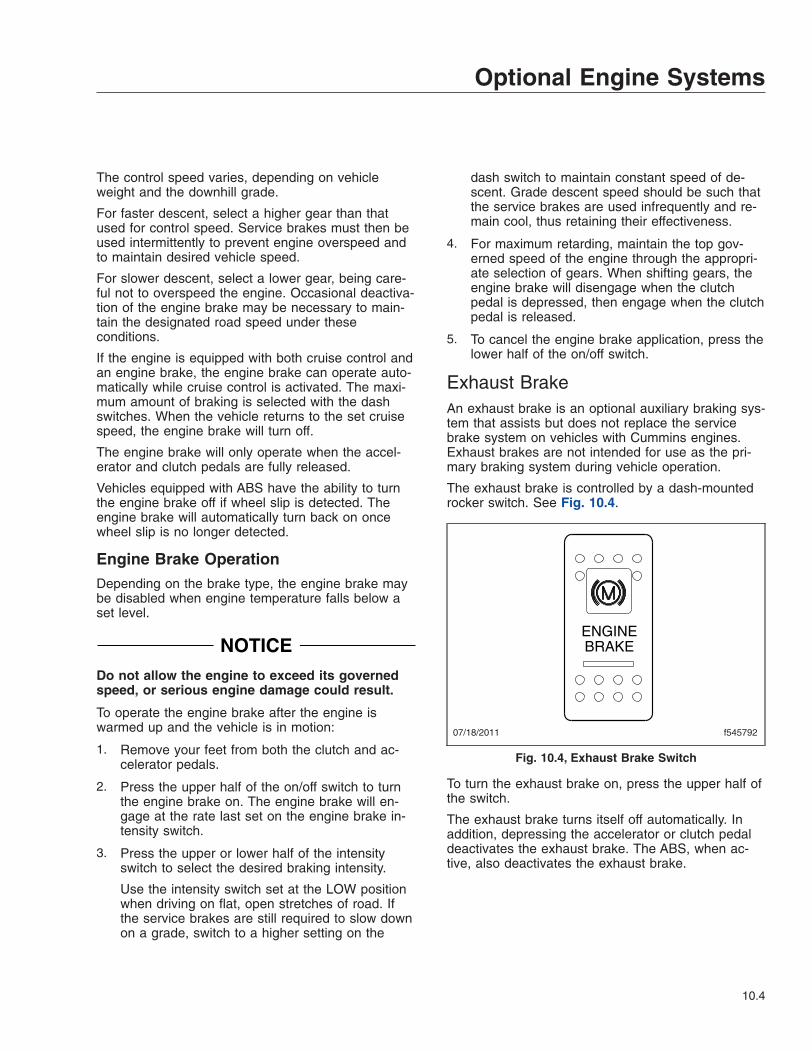
The control speed varies, depending on vehicleweight and the downhill grade.
For faster descent, select a higher gear than thatused for control speed. Service brakes must then beused intermittently to prevent engine overspeed andto maintain desired vehicle speed.
For slower descent, select a lower gear, being care-ful not to overspeed the engine. Occasional deactiva-tion of the engine brake may be necessary to main-tain the designated road speed under theseconditions.
If the engine is equipped with both cruise control andan engine brake, the engine brake can operate auto-matically while cruise control is activated. The maxi-mum amount of braking is selected with the dashswitches. When the vehicle returns to the set cruisespeed, the engine brake will turn off.
The engine brake will only operate when the accel-erator and clutch pedals are fully released.
Vehicles equipped with ABS have the ability to turnthe engine brake off if wheel slip is detected. Theengine brake will automatically turn back on oncewheel slip is no longer detected.
Engine Brake OperationDepending on the brake type, the engine brake maybe disabled when engine temperature falls below aset level.
NOTICEDo not allow the engine to exceed its governedspeed, or serious engine damage could result.
To operate the engine brake after the engine iswarmed up and the vehicle is in motion:
1. Remove your feet from both the clutch and ac-celerator pedals.
2. Press the upper half of the on/off switch to turnthe engine brake on. The engine brake will en-gage at the rate last set on the engine brake in-tensity switch.
3. Press the upper or lower half of the intensityswitch to select the desired braking intensity.
Use the intensity switch set at the LOW positionwhen driving on flat, open stretches of road. Ifthe service brakes are still required to slow downon a grade, switch to a higher setting on the
dash switch to maintain constant speed of de-scent. Grade descent speed should be such thatthe service brakes are used infrequently and re-main cool, thus retaining their effectiveness.
4. For maximum retarding, maintain the top gov-erned speed of the engine through the appropri-ate selection of gears. When shifting gears, theengine brake will disengage when the clutchpedal is depressed, then engage when the clutchpedal is released.
5. To cancel the engine brake application, press thelower half of the on/off switch.
Exhaust BrakeAn exhaust brake is an optional auxiliary braking sys-tem that assists but does not replace the servicebrake system on vehicles with Cummins engines.Exhaust brakes are not intended for use as the pri-mary braking system during vehicle operation.
The exhaust brake is controlled by a dash-mountedrocker switch. See Fig. 10.4.
To turn the exhaust brake on, press the upper half ofthe switch.
The exhaust brake turns itself off automatically. Inaddition, depressing the accelerator or clutch pedaldeactivates the exhaust brake. The ABS, when ac-tive, also deactivates the exhaust brake.
07/18/2011 f545792
ENGINEBRAKE
Fig. 10.4, Exhaust Brake Switch
Optional Engine Systems
10.4
Exhaust Brake Operation
WARNINGDo not use the exhaust brake when driving onslippery or low-traction road surfaces. Failure tofollow this precaution could result in a loss ofvehicle control and possible personal injury orproperty damage.
1. Before starting the engine, make sure that theexhaust brake is off. Wait until the engine hasreached normal operating temperature beforeactivating the exhaust brake.
2. When approaching a downhill grade, press theupper half of the exhaust brake switch to turn theexhaust brake on. When the exhaust brake is on,the status bar is illuminated.
3. Remove your feet from the accelerator andclutch pedals.
NOTICEDo not allow the engine to exceed its governedspeed, or serious engine damage could result.
NOTE: The exhaust brake is only active whenengine speed is between 1100 and 2700 rpm.
4. While going down a grade, use a low enoughgear to safely descend with a minimum applica-tion of the service brakes. As a general guide-line, use the same gear as you would to ascendthe hill.
The following conditions should exist if the brakeis operating properly:
• A slight change in the sound of the enginemay be noticeable.
• Exhaust smoke should appear normal.
• Engine temperature should remain in thenormal operating range.
• Road speed will usually decrease when theexhaust brake is applied during a descent.When the vehicle is carrying a heavy loador the grade is extremely steep, you mayneed to apply the service brakes occasion-ally.
• The exhaust brake retards the vehicle witha smooth braking effect.
• During a descent, the tachometer usuallyshows a drop in rpm, depending on thegrade and the vehicle load.
• Depending on the grade and vehicle load,the retarding force of the exhaust brakemay be noticeable.
5. Apply the service brakes to reduce engine rpmor make a slower descent by using a lower gear.
6. Make sure the exhaust brake is turned off beforeshutting down the engine.
Power Takeoff (PTO) GovernorEngine power takeoffs (PTO) are devices used to tapinto engine power to run auxiliary devices, such ashydraulic pumps that power additional equipment.The following are general guidelines for operating aPTO.
• Set the parking brake and put the transmissionin neutral.
• Press the upper half of the PTO switch. Whenthe status bar light is steadily illuminated, thePTO is engaged and ready to operate. In sta-tionary mode, the vehicle must remain in neu-tral with the parking brake set.
• To activate the mobile mode, shift from neutralto reverse, 1st, or 2nd gear. The clutch willopen and the PTO will disengage for a mo-ment.
• Touch the accelerator pedal to close the clutchand engage the PTO in mobile mode. ThePTO may be operated with the transmission inneutral or reverse, 1st, or 2nd gears only. Donot attempt to change gears while the vehicleis moving. The transmission will ignore the re-quest.
• To deactivate mobile mode, bring the vehicle toa stop. The clutch will open and shut downpower to the PTO.
• To resume stationary mode, shift to neutral.The PTO will engage.
• To deactivate stationary mode, press the lowerhalf of the PTO switch. When the light in theswitch goes out, power to the PTO is shut off.
Optional Engine Systems
10.5
11
Emissions and FuelEfficiency
Greenhouse Gas Emissions and Fuel Consumption Standards . . . . . . . . . . . . . . . . . . . . . . . . . . . 11.1EPA-Regulated Emissions Aftertreatment Systems . . . . . . . . . . . . . . . . . . . . . . . . . . . . . . . . . . . . . 11.1Diesel Exhaust Fluid and Tank, EPA10 and Newer Engines . . . . . . . . . . . . . . . . . . . . . . . . . . . . . . 11.4
Greenhouse Gas Emissionsand Fuel ConsumptionStandardsVehicles and/or engines manufactured after Decem-ber 31, 2006 and domiciled in the U.S. or Canadaare required to meet all EPA and NHTSA regulationseffective as of the vehicle build date. Engines manu-factured between January 1, 2007 and December 31,2009 meet EPA07 requirements. Engines manufac-tured between January 1, 2010 and December 31,2012 meet EPA10 requirements. Engines manufac-tured from January 1, 2013 meet NHTSA and EPA2014 fuel efficiency and greenhouse gas emissionstandards (GHG14) requirements. Engines manufac-tured from January 1, 2016 meet NHTSA and EPA2017 fuel efficiency and greenhouse gas emissionstandards (GHG17) requirements.
Model year 2013 and later vehicles meet additionalrequirements as specified by GHG14 requirements.Model year 2017 and later vehicles meet similar re-quirements as specified by GHG17 requirements.These vehicles are equipped with components thatincrease fuel efficiency and reduce GHG emissions.Components may include, but are not limited to, low-rolling resistance tires; aerodynamic devices such ashood, cab/sleeper extenders, and fuel tank fairings;vehicle speed limiter; and idle shutdown timer. If re-placement of any drag-reducing component is re-quired, the replacement component must meet orexceed the drag reduction performance of the origi-nally installed component in order to maintain compli-ance with GHG14 and GHG17.
EPA-Regulated EmissionsAftertreatment SystemsIMPORTANT: Depending on local jurisdictionalguidelines, vehicles that are domiciled outside ofthe U.S. and Canada may not have emissionsaftertreatment systems (ATS) that are compliantwith EPA regulations.
NOTICEFollow these guidelines for engines that complywith EPA07 or newer regulations, or damage mayoccur to the aftertreatment device (ATD) and thewarranty may be compromised.
• Use ultralow-sulfur diesel with 15 ppm sul-fur content or less.
• Do not use fuel blended with used enginelube oil or kerosene.
• Engine lube oil must have a sulfated ashlevel less than 1.0 wt %; currently referredto as CJ-4 oil.
IMPORTANT: Using non-specification fuels oroils can lead to shortened diesel particulate filter(DPF) cleaning or replacement intervals. Forexample, using CJ-4+ oil with 1.3% sulfated ash(30% more ash content) may result in the needfor DPF cleaning or replacement 20 to 30%sooner than would normally be required.
IMPORTANT: See the engine manufacturer’soperation manual for complete details and op-eration of the ATS.
EPA07 EnginesEngines built between January 1, 2007 and Decem-ber 31, 2009 are required to meet EPA07 guidelinesfor reduced exhaust emissions of particulate matterand nitrogen oxides (NOx). NOx is limited to justover 1 gram per brake horsepower hour (g/bhp-hr),and particulate matter cannot exceed 0.01 g/bhp-hr.
The EPA07 ATS varies according to engine manufac-turer and vehicle configuration, but the exhaust muf-fler is replaced by an aftertreatment device (ATD).Inside the ATD, the exhaust first passes over the die-sel oxidation catalyst (DOC), then passes throughthe diesel particulate filter (DPF), which traps sootparticles. The soot is burned to ash during a processcalled regeneration (regen).
EPA10 and Newer EnginesThe EPA mandates that all engines built after De-cember 31, 2009 must reduce the level of emissionsexhausted by the engine to the following levels:
• Nitrogen Oxides (NOx) – 0.2 g/bhp-hr
• Particulate Matter (PM) – .01 g/bhp-hr
To meet EPA guidelines, engines that are compliantwith EPA10 and newer regulations use an ATS thathas, in addition to a DOC/DPF device like that usedin an EPA07 ATD, a Selective Catalytic Reduction(SCR) devide to reduce NOx downstream of the en-gine. After exhaust gases leave the DPF, a controlled
Emissions and Fuel Efficiency
11.1
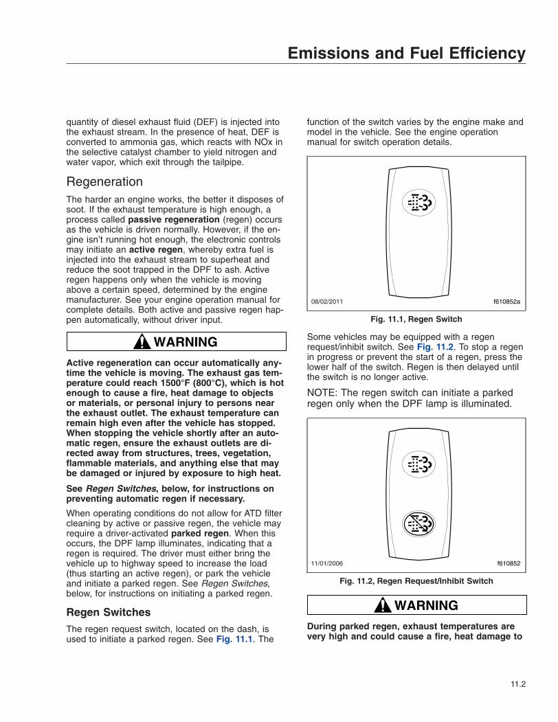
quantity of diesel exhaust fluid (DEF) is injected intothe exhaust stream. In the presence of heat, DEF isconverted to ammonia gas, which reacts with NOx inthe selective catalyst chamber to yield nitrogen andwater vapor, which exit through the tailpipe.
RegenerationThe harder an engine works, the better it disposes ofsoot. If the exhaust temperature is high enough, aprocess called passive regeneration (regen) occursas the vehicle is driven normally. However, if the en-gine isn’t running hot enough, the electronic controlsmay initiate an active regen, whereby extra fuel isinjected into the exhaust stream to superheat andreduce the soot trapped in the DPF to ash. Activeregen happens only when the vehicle is movingabove a certain speed, determined by the enginemanufacturer. See your engine operation manual forcomplete details. Both active and passive regen hap-pen automatically, without driver input.
WARNINGActive regeneration can occur automatically any-time the vehicle is moving. The exhaust gas tem-perature could reach 1500°F (800°C), which is hotenough to cause a fire, heat damage to objectsor materials, or personal injury to persons nearthe exhaust outlet. The exhaust temperature canremain high even after the vehicle has stopped.When stopping the vehicle shortly after an auto-matic regen, ensure the exhaust outlets are di-rected away from structures, trees, vegetation,flammable materials, and anything else that maybe damaged or injured by exposure to high heat.
See Regen Switches, below, for instructions onpreventing automatic regen if necessary.
When operating conditions do not allow for ATD filtercleaning by active or passive regen, the vehicle mayrequire a driver-activated parked regen. When thisoccurs, the DPF lamp illuminates, indicating that aregen is required. The driver must either bring thevehicle up to highway speed to increase the load(thus starting an active regen), or park the vehicleand initiate a parked regen. See Regen Switches,below, for instructions on initiating a parked regen.
Regen SwitchesThe regen request switch, located on the dash, isused to initiate a parked regen. See Fig. 11.1. The
function of the switch varies by the engine make andmodel in the vehicle. See the engine operationmanual for switch operation details.
Some vehicles may be equipped with a regenrequest/inhibit switch. See Fig. 11.2. To stop a regenin progress or prevent the start of a regen, press thelower half of the switch. Regen is then delayed untilthe switch is no longer active.
NOTE: The regen switch can initiate a parkedregen only when the DPF lamp is illuminated.
WARNINGDuring parked regen, exhaust temperatures arevery high and could cause a fire, heat damage to
08/02/2011 f610852a
Fig. 11.1, Regen Switch
11/01/2006 f610852
Fig. 11.2, Regen Request/Inhibit Switch
Emissions and Fuel Efficiency
11.2

objects or materials, or personal injury to per-sons near the exhaust outlet.
Before initiating a parked regen, make certain theexhaust outlets are directed away from struc-tures, trees, vegetation, flammable materials, andanything else that may be damaged or injured byprolonged exposure to high heat.
To initiate a parked regen, perform the followingsteps.
1. Park the vehicle away from all flammable materi-als, put the transmission in neutral, and set theparking brake.
2. Start and warm the engine until the coolant tem-perature is at least 150°F (66°C).
3. Press and hold the regen switch for five sec-onds. The engine will increase rpm and initiatethe regen process. As the regen process is initi-ated, engine rpm increases and the HEST lampilluminates to indicate extremely high exhausttemperatures.
IMPORTANT: The driver must remain with thevehicle during the entire regen cycle.
4. The regen cycle will finish after 20 to 60 minutes,at which time engine idle speed drops to normaland the vehicle can be driven normally. TheHEST lamp is extinguished when vehicle speedexceeds 5 mph (8 km/h) or the system hascooled to normal operating temperature.
5. To stop a parked regen at any time during theprocess:
• depress the clutch pedal, brake pedal, oraccelerator pedal;
• press and hold the regen inhibit switch untilidle returns to normal;
• shut down the engine.
ATS Warning LampsThere are three warning lamps that alert the driver ofhigh exhaust temperature, the need to perform aparked regen or service the DPF, or of an enginefault that affects emissions. A decal attached to thedriver’s sun visor explains the ATS warning lamps.See Fig. 11.3.
See Fig. 11.4 for an explanation of the ATS warn-ings, and actions required to avoid engine protectionsequences.
Malfunction Indicator Lamp (MIL)A steadily illuminated yellow malfunction indicatorlamp (MIL) indicates an engine fault that affects theemissions. See Fig. 11.5.
DPF LampWhen soot accumulates in the DPF and the DPF sta-tus lamp illuminates, see Fig. 11.6, perform a parkedregen or bring the vehicle up to highway speed toincrease the load (thus starting an active regen).
If the DPF status lamp blinks while the CHECK en-gine lamp is illuminated, initiate a parked regen im-mediately in order to prevent an engine derate.
If the red STOP engine lamp illuminates with theblinking DPF lamp and the CHECK engine lamp,begin a parked regen in order to prevent an engineshutdown. Park the vehicle and perform a parkedregen.
High Exhaust System Temperature(HEST) LampSlow (10-second) flashing of the high exhaust sys-tem temperature (HEST) lamp indicates that aparked regen is in progress, and the engine’s highidle speed is being controlled by the engine software,not the vehicle driver.
Steady illumination of the HEST lamp alerts thedriver of high exhaust temperature during the regenprocess if the vehicle speed is below 5 mph (8 km/h), or during a parked regen. See Fig. 11.7.
MaintenanceAuthorized service facilities must perform any DPFservice. For warranty purposes, maintain a recordthat includes:
• date of cleaning or replacement;
• vehicle mileage;
• particulate filter part number and serial number.
Emissions and Fuel Efficiency
11.3
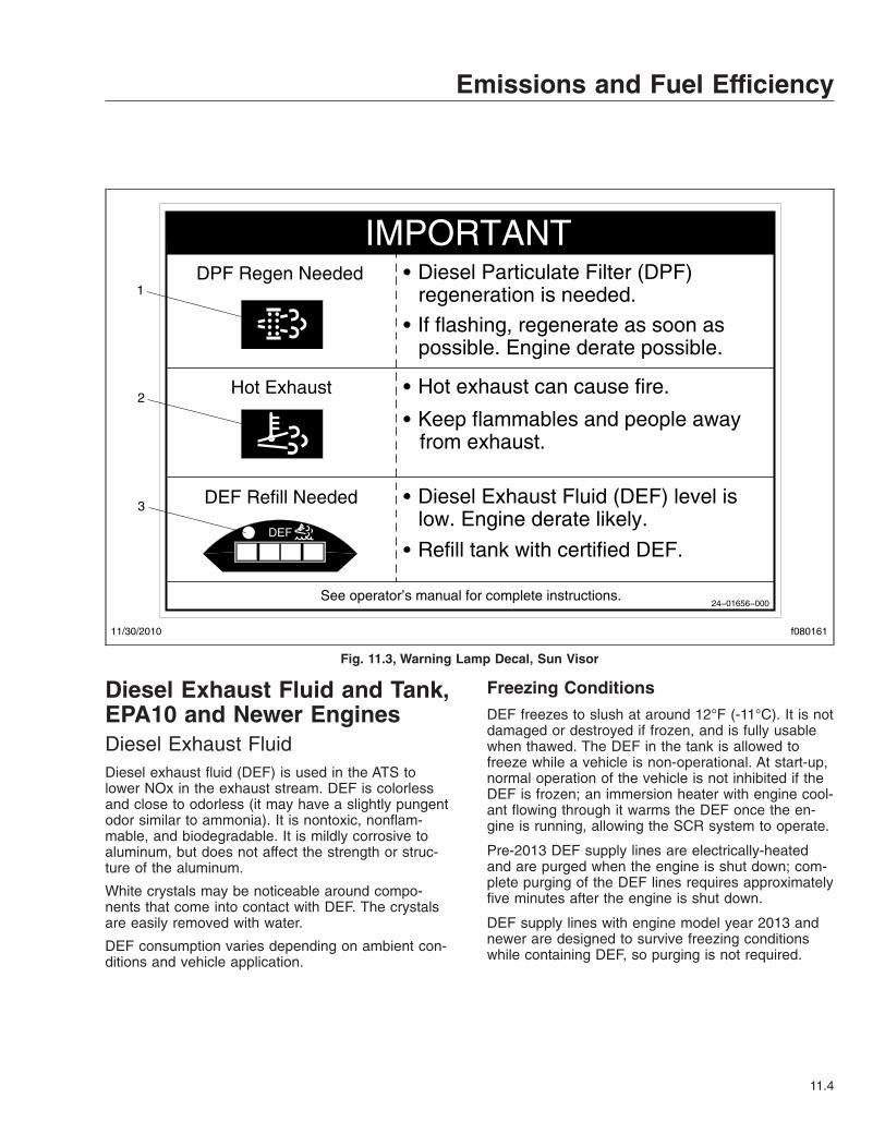
Diesel Exhaust Fluid and Tank,EPA10 and Newer EnginesDiesel Exhaust FluidDiesel exhaust fluid (DEF) is used in the ATS tolower NOx in the exhaust stream. DEF is colorlessand close to odorless (it may have a slightly pungentodor similar to ammonia). It is nontoxic, nonflam-mable, and biodegradable. It is mildly corrosive toaluminum, but does not affect the strength or struc-ture of the aluminum.
White crystals may be noticeable around compo-nents that come into contact with DEF. The crystalsare easily removed with water.
DEF consumption varies depending on ambient con-ditions and vehicle application.
Freezing ConditionsDEF freezes to slush at around 12°F (-11°C). It is notdamaged or destroyed if frozen, and is fully usablewhen thawed. The DEF in the tank is allowed tofreeze while a vehicle is non-operational. At start-up,normal operation of the vehicle is not inhibited if theDEF is frozen; an immersion heater with engine cool-ant flowing through it warms the DEF once the en-gine is running, allowing the SCR system to operate.
Pre-2013 DEF supply lines are electrically-heatedand are purged when the engine is shut down; com-plete purging of the DEF lines requires approximatelyfive minutes after the engine is shut down.
DEF supply lines with engine model year 2013 andnewer are designed to survive freezing conditionswhile containing DEF, so purging is not required.
DPF Regen Needed
Hot Exhaust
DEF Refill Needed
Diesel Particulate Filter (DPF)regeneration is needed.
If flashing, regenerate as soon aspossible. Engine derate possible.
Hot exhaust can cause fire.
Keep flammables and people awayfrom exhaust.
Diesel Exhaust Fluid (DEF) level islow. Engine derate likely.
Refill tank with certified DEF.
See operator’s manual for complete instructions.24−01656−000
IMPORTANT
DEF
11/30/2010 f080161
1
2
3
Fig. 11.3, Warning Lamp Decal, Sun Visor
Emissions and Fuel Efficiency
11.4

DEF TankEngines that are compliant with EPA10 and newerregulations are equipped with a DEF tank located onthe driver’s side of the vehicle behind the battery boxor forward of the fuel tank. See Fig. 11.8. The DEFtank has a 19 mm filler neck inlet that prevents thehose from a diesel outlet from being inserted, andhas a blue cap for easy identification.
Fuel/DEF GaugeThe diesel fuel and DEF levels are measured in adual-purpose gauge. See Fig. 11.9.
Fuel level is indicated at the top of the gauge. Belowthe fuel level, a low fuel warning lamp illuminatesamber when the fuel level drops below 1/8th of thecapacity.
The lower portion of the gauge has a DEF warninglamp that illuminates amber when the DEF tank isnear empty, and a lightbar that indicates the level of
f080147
EXHAUST AFTERTREATMENT SYSTEM INFORMATION
Switch.
Level 1 Level 3Level 2 Level 4Filter RegenerationRecommended
Filter is reaching
Bring vehicle tohighway speeds to
Filter RegenerationNecessary
Filter is nowreaching maximumcapacity.
To avoid enginederate bring vehicle
Parked RegenerationRequired − EngineDerate
Filter has reachedmaximum capacity.
Vehicle must beparked and a Parked
Parked Regeneration Required −Engine Shut Down
Filter has exceededmaximum capacity
Vehicle must be parked and aParked Regeneration or Service
(Solid) (Flashing) (Flashing)
CHECK CHECK
(Flashing)
INDICATORLAMP(S)
Indicator LampMessage(s)
Diesel ParticulateFilter Condition
Required Action
capacity. .
STOP
See Engine Operator’s Manual for complete Regeneration Instructions.
allow for an AutomaticRegeneration orperform a ParkedRegeneration.
to highway speedsto allow for anAutomaticRegeneration orperform a ParkedRegeneration assoon as possible.
Regeneration mustbe performed −engine will beginderate.
Regeneration must be performed.Check engine operator’s manualfor details −engine will shut down.
For a driver performed Parked Regeneration, vehicle must be equipped with a dash mounted Regeneration Switch.
06/29/2009
24−01583−000B
WARNING
HEST (High ExhaustSystem Temperature)
Exhaust Componentsand exhaust gas areat high temperature. When stationary, keepaway from people andflammable materialsor vapors.
A regeneration is inprogress.
Flashing
Solid
Fig. 11.4, ATS Warning Lamps
09/25/2006 f610814a
Fig. 11.5, Malfunction Indicator Lamp (MIL)
09/25/2006 f610815a
Fig. 11.6, Diesel Particulate Filter (DPF) Status Lamp
Emissions and Fuel Efficiency
11.5

DEF in the tank. The DEF light bar illuminates as fol-lows.
• Four bars illuminated green—Between 75%and 100% full
• Three bars illuminated green—Between 50%and 75% full
• Two bars illuminated green—Between 25%and 50% full
• One bar illuminated green—Between approxi-mately 10% and 25% full
• One bar illuminated amber—DEF very low, re-fill DEF
• One bar flashing red—DEF empty, refill DEF
DEF Warnings and Engine LimitsIMPORTANT: Ignoring the DEF warning lightsresults in limited engine power, with the applica-tion of a 5 mph (8 km/h) speed limit.
DEF Level Low—Initial WarningWhen the DEF level is low, the following lamps notifythe driver. See Fig. 11.10. Refill the DEF tank inorder to cancel the warning sequence.
• One bar of the DEF level indicator illuminatesamber—DEF very low, refill DEF.
• The DEF warning lamp illuminates solid amber.
DEF EmptyWhen the DEF level reads empty, the followinglamps notify the drive. See Fig. 11.11.
• One bar of the DEF level indicator flashesred—DEF empty, refill DEF.
• The DEF warning lamp flashes amber.
• The MIL lamp illuminates.
Pre-2013 Detroit engines: Power is limited, with a 55mph (90 km/h) speed limit.
Cummins and 2013 Detroit engines: Power is limitedwith progressively harsher engine power limitsapplied.
DEF Tank Empty and IgnoredIf the empty warning is ignored and the DEF tank isnot refilled, the red STOP engine lamp illuminates inaddition to the MIL lamp and CHECK engine lamp(on vehicles with a Cummins ISB or ISC/L engine.)See Fig. 11.12.
If the DEF is not refilled, a 5 mph (8 km/h) speedlimit is applied after the next engine shutdown, whileparked and idling, or if a fuel refill is detected.
DEF Contamination or SCR Tampering
NOTICEOnce contaminated DEF or tampering has beendetected, the vehicle must be taken to an autho-rized service facility to check the SCR system fordamage and to deactivate the warning lights andengine limits.
09/25/2006 f610816a
Fig. 11.7, High Exhaust System Temperature (HEST)Lamp
07/24/2009 f470541
12
1. DEF Tank 2. Fuel Tank
Fig. 11.8, DEF Tank Located Forward of the Fuel Tank
Emissions and Fuel Efficiency
11.6
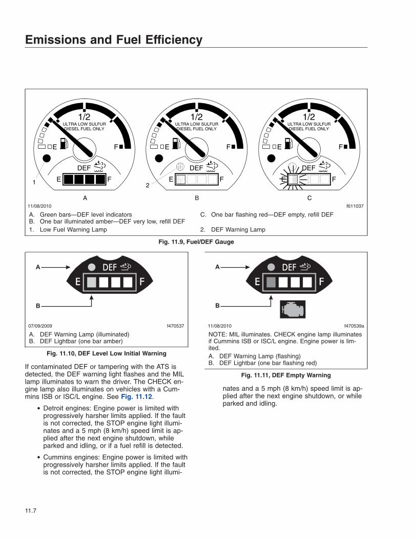
If contaminated DEF or tampering with the ATS isdetected, the DEF warning light flashes and the MILlamp illuminates to warn the driver. The CHECK en-gine lamp also illuminates on vehicles with a Cum-mins ISB or ISC/L engine. See Fig. 11.12.
• Detroit engines: Engine power is limited withprogressively harsher limits applied. If the faultis not corrected, the STOP engine light illumi-nates and a 5 mph (8 km/h) speed limit is ap-plied after the next engine shutdown, whileparked and idling, or if a fuel refill is detected.
• Cummins engines: Engine power is limited withprogressively harsher limits applied. If the faultis not corrected, the STOP engine light illumi-
nates and a 5 mph (8 km/h) speed limit is ap-plied after the next engine shutdown, or whileparked and idling.
11/08/2010 f611037
B
1/2ULTRA LOW SULFURDIESEL FUEL ONLY
E F
DEF
FE
1/2ULTRA LOW SULFURDIESEL FUEL ONLY
E F
DEF
FE
1/2ULTRA LOW SULFURDIESEL FUEL ONLY
E F
DEF
FE
A C
1 2
A. Green bars—DEF level indicatorsB. One bar illuminated amber—DEF very low, refill DEF
C. One bar flashing red—DEF empty, refill DEF
1. Low Fuel Warning Lamp 2. DEF Warning Lamp
Fig. 11.9, Fuel/DEF Gauge
A
B
07/09/2009 f470537
A. DEF Warning Lamp (illuminated)B. DEF Lightbar (one bar amber)
Fig. 11.10, DEF Level Low Initial Warning
A
B
11/08/2010 f470539a
NOTE: MIL illuminates. CHECK engine lamp illuminatesif Cummins ISB or ISC/L engine. Engine power is lim-ited.A. DEF Warning Lamp (flashing)B. DEF Lightbar (one bar flashing red)
Fig. 11.11, DEF Empty Warning
Emissions and Fuel Efficiency
11.7
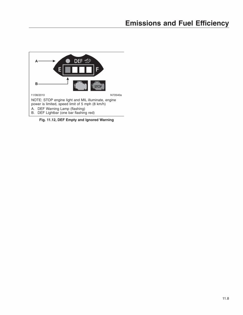
A
B
11/08/2010 f470540a
NOTE: STOP engine light and MIL illuminate, enginepower is limited, speed limit of 5 mph (8 km/h)A. DEF Warning Lamp (flashing)B. DEF Lightbar (one bar flashing red)
Fig. 11.12, DEF Empty and Ignored Warning
Emissions and Fuel Efficiency
11.8
12
Brake SystemsAir Brake System . . . . . . . . . . . . . . . . . . . . . . . . . . . . . . . . . . . . . . . . . . . . . . . . . . . . . . . . . . . . . . . . 12.1Meritor WABCO® Antilock Braking System . . . . . . . . . . . . . . . . . . . . . . . . . . . . . . . . . . . . . . . . . . . 12.3Roll-Stability Control . . . . . . . . . . . . . . . . . . . . . . . . . . . . . . . . . . . . . . . . . . . . . . . . . . . . . . . . . . . . . . 12.5
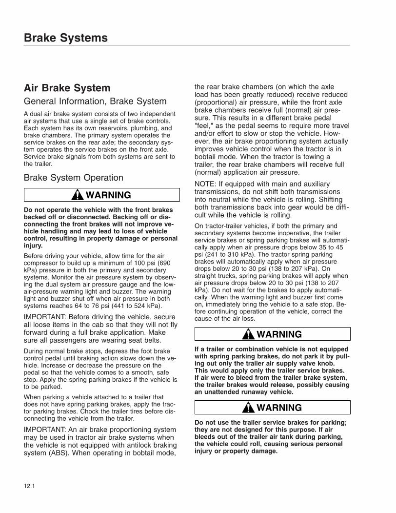
Air Brake SystemGeneral Information, Brake SystemA dual air brake system consists of two independentair systems that use a single set of brake controls.Each system has its own reservoirs, plumbing, andbrake chambers. The primary system operates theservice brakes on the rear axle; the secondary sys-tem operates the service brakes on the front axle.Service brake signals from both systems are sent tothe trailer.
Brake System Operation
WARNINGDo not operate the vehicle with the front brakesbacked off or disconnected. Backing off or dis-connecting the front brakes will not improve ve-hicle handling and may lead to loss of vehiclecontrol, resulting in property damage or personalinjury.
Before driving your vehicle, allow time for the aircompressor to build up a minimum of 100 psi (690kPa) pressure in both the primary and secondarysystems. Monitor the air pressure system by observ-ing the dual system air pressure gauge and the low-air-pressure warning light and buzzer. The warninglight and buzzer shut off when air pressure in bothsystems reaches 64 to 76 psi (441 to 524 kPa).
IMPORTANT: Before driving the vehicle, secureall loose items in the cab so that they will not flyforward during a full brake application. Makesure all passengers are wearing seat belts.
During normal brake stops, depress the foot brakecontrol pedal until braking action slows down the ve-hicle. Increase or decrease the pressure on thepedal so that the vehicle comes to a smooth, safestop. Apply the spring parking brakes if the vehicle isto be parked.
When parking a vehicle attached to a trailer thatdoes not have spring parking brakes, apply the trac-tor parking brakes. Chock the trailer tires before dis-connecting the vehicle from the trailer.
IMPORTANT: An air brake proportioning systemmay be used in tractor air brake systems whenthe vehicle is not equipped with antilock brakingsystem (ABS). When operating in bobtail mode,
the rear brake chambers (on which the axleload has been greatly reduced) receive reduced(proportional) air pressure, while the front axlebrake chambers receive full (normal) air pres-sure. This results in a different brake pedal"feel," as the pedal seems to require more traveland/or effort to slow or stop the vehicle. How-ever, the air brake proportioning system actuallyimproves vehicle control when the tractor is inbobtail mode. When the tractor is towing atrailer, the rear brake chambers will receive full(normal) application air pressure.
NOTE: If equipped with main and auxiliarytransmissions, do not shift both transmissionsinto neutral while the vehicle is rolling. Shiftingboth transmissions back into gear would be diffi-cult while the vehicle is rolling.
On tractor-trailer vehicles, if both the primary andsecondary systems become inoperative, the trailerservice brakes or spring parking brakes will automati-cally apply when air pressure drops below 35 to 45psi (241 to 310 kPa). The tractor spring parkingbrakes will automatically apply when air pressuredrops below 20 to 30 psi (138 to 207 kPa). Onstraight trucks, spring parking brakes will apply whenair pressure drops below 20 to 30 psi (138 to 207kPa). Do not wait for the brakes to apply automati-cally. When the warning light and buzzer first comeon, immediately bring the vehicle to a safe stop. Be-fore continuing operation of the vehicle, correct thecause of the air loss.
WARNINGIf a trailer or combination vehicle is not equippedwith spring parking brakes, do not park it by pull-ing out only the trailer air supply valve knob.This would apply only the trailer service brakes.If air were to bleed from the trailer brake system,the trailer brakes would release, possibly causingan unattended runaway vehicle.
WARNINGDo not use the trailer service brakes for parking;they are not designed for this purpose. If airbleeds out of the trailer air tank during parking,the vehicle could roll, causing serious personalinjury or property damage.
Brake Systems
12.1
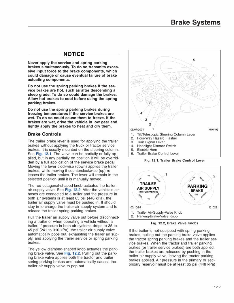
NOTICENever apply the service and spring parkingbrakes simultaneously. To do so transmits exces-sive input force to the brake components, whichcould damage or cause eventual failure of brakeactuating components.
Do not use the spring parking brakes if the ser-vice brakes are hot, such as after descending asteep grade. To do so could damage the brakes.Allow hot brakes to cool before using the springparking brakes.
Do not use the spring parking brakes duringfreezing temperatures if the service brakes arewet. To do so could cause them to freeze. If thebrakes are wet, drive the vehicle in low gear andlightly apply the brakes to heat and dry them.
Brake ControlsThe trailer brake lever is used for applying the trailerbrakes without applying the truck or tractor servicebrakes. It is usually mounted on the steering column.See Fig. 12.1. The valve can be partially or fully ap-plied, but in any partially on position it will be overrid-den by a full application of the service brake pedal.Moving the lever clockwise (down) applies the trailerbrakes, while moving it counterclockwise (up) re-leases the trailer brakes. The lever will remain in theselected position until it is manually moved.
The red octagonal-shaped knob actuates the trailerair supply valve. See Fig. 12.2. After the vehicle’s airhoses are connected to a trailer and the pressure inboth air systems is at least 65 psi (448 kPa), thetrailer air supply valve must be pushed in. It shouldstay in to charge the trailer air supply system and torelease the trailer spring parking brakes.
Pull the trailer air supply valve out before disconnect-ing a trailer or when operating a vehicle without atrailer. If pressure in both air systems drops to 35 to45 psi (241 to 310 kPa), the trailer air supply valveautomatically pops out, exhausting the trailer air sup-ply, and applying the trailer service or spring parkingbrakes.
The yellow diamond-shaped knob actuates the park-ing brake valve. See Fig. 12.2. Pulling out the park-ing brake valve applies both the tractor and trailerspring parking brakes and automatically causes thetrailer air supply valve to pop out.
If the trailer is not equipped with spring parkingbrakes, pulling out the parking brake valve appliesthe tractor spring parking brakes and the trailer ser-vice brakes. When the tractor and trailer parkingbrakes (or trailer service brakes) are both applied,the trailer brakes are released by pushing in thetrailer air supply valve, leaving the tractor parkingbrakes applied. Air pressure in the primary or sec-ondary reservoir must be at least 65 psi (448 kPa)
05/07/2001 f61049312
3
4
5
6
1. Tilt/Telescopic Steering Column Lever2. Four-Way Hazard Flasher3. Turn Signal Lever4. Headlight Dimmer Switch5. Electric Horn6. Trailer Brake Control Lever
Fig. 12.1, Trailer Brake Control Lever
f610291
1 2
03/10/99
1. Trailer Air-Supply-Valve Knob2. Parking-Brake-Valve Knob
Fig. 12.2, Brake Valve Knobs
Brake Systems
12.2
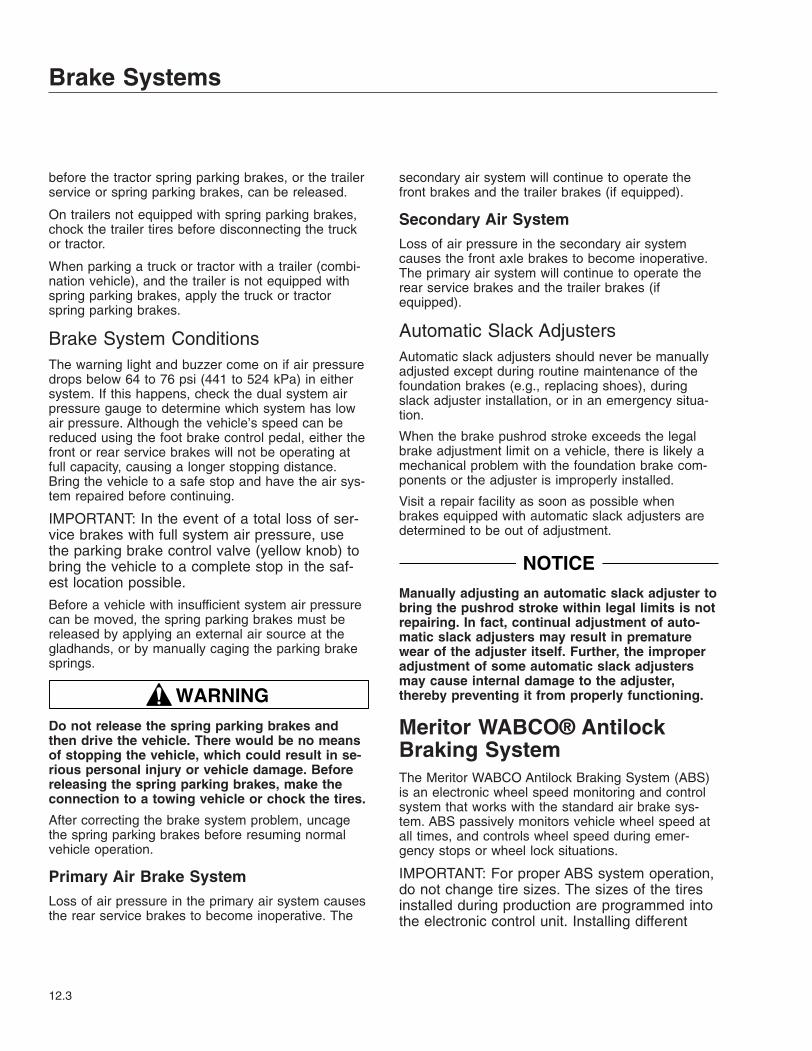
before the tractor spring parking brakes, or the trailerservice or spring parking brakes, can be released.
On trailers not equipped with spring parking brakes,chock the trailer tires before disconnecting the truckor tractor.
When parking a truck or tractor with a trailer (combi-nation vehicle), and the trailer is not equipped withspring parking brakes, apply the truck or tractorspring parking brakes.
Brake System ConditionsThe warning light and buzzer come on if air pressuredrops below 64 to 76 psi (441 to 524 kPa) in eithersystem. If this happens, check the dual system airpressure gauge to determine which system has lowair pressure. Although the vehicle’s speed can bereduced using the foot brake control pedal, either thefront or rear service brakes will not be operating atfull capacity, causing a longer stopping distance.Bring the vehicle to a safe stop and have the air sys-tem repaired before continuing.
IMPORTANT: In the event of a total loss of ser-vice brakes with full system air pressure, usethe parking brake control valve (yellow knob) tobring the vehicle to a complete stop in the saf-est location possible.
Before a vehicle with insufficient system air pressurecan be moved, the spring parking brakes must bereleased by applying an external air source at thegladhands, or by manually caging the parking brakesprings.
WARNINGDo not release the spring parking brakes andthen drive the vehicle. There would be no meansof stopping the vehicle, which could result in se-rious personal injury or vehicle damage. Beforereleasing the spring parking brakes, make theconnection to a towing vehicle or chock the tires.
After correcting the brake system problem, uncagethe spring parking brakes before resuming normalvehicle operation.
Primary Air Brake SystemLoss of air pressure in the primary air system causesthe rear service brakes to become inoperative. The
secondary air system will continue to operate thefront brakes and the trailer brakes (if equipped).
Secondary Air SystemLoss of air pressure in the secondary air systemcauses the front axle brakes to become inoperative.The primary air system will continue to operate therear service brakes and the trailer brakes (ifequipped).
Automatic Slack AdjustersAutomatic slack adjusters should never be manuallyadjusted except during routine maintenance of thefoundation brakes (e.g., replacing shoes), duringslack adjuster installation, or in an emergency situa-tion.
When the brake pushrod stroke exceeds the legalbrake adjustment limit on a vehicle, there is likely amechanical problem with the foundation brake com-ponents or the adjuster is improperly installed.
Visit a repair facility as soon as possible whenbrakes equipped with automatic slack adjusters aredetermined to be out of adjustment.
NOTICEManually adjusting an automatic slack adjuster tobring the pushrod stroke within legal limits is notrepairing. In fact, continual adjustment of auto-matic slack adjusters may result in prematurewear of the adjuster itself. Further, the improperadjustment of some automatic slack adjustersmay cause internal damage to the adjuster,thereby preventing it from properly functioning.
Meritor WABCO® AntilockBraking SystemThe Meritor WABCO Antilock Braking System (ABS)is an electronic wheel speed monitoring and controlsystem that works with the standard air brake sys-tem. ABS passively monitors vehicle wheel speed atall times, and controls wheel speed during emer-gency stops or wheel lock situations.
IMPORTANT: For proper ABS system operation,do not change tire sizes. The sizes of the tiresinstalled during production are programmed intothe electronic control unit. Installing different
Brake Systems
12.3
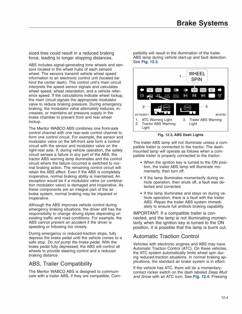
sized tires could result in a reduced brakingforce, leading to longer stopping distances.
ABS includes signal-generating tone wheels and sen-sors located in the wheel hubs of each sensedwheel. The sensors transmit vehicle wheel speedinformation to an electronic control unit (located be-hind the center dash). The control unit’s main circuitinterprets the speed sensor signals and calculateswheel speed, wheel retardation, and a vehicle refer-ence speed. If the calculations indicate wheel lockup,the main circuit signals the appropriate modulatorvalve to reduce braking pressure. During emergencybraking, the modulator valve alternately reduces, in-creases, or maintains air pressure supply in thebrake chamber to prevent front and rear wheellockup.
The Meritor WABCO ABS combines one front-axlecontrol channel with one rear-axle control channel toform one control circuit. For example, the sensor andmodulator valve on the left-front axle form a controlcircuit with the sensor and modulator valve on theright-rear axle. If, during vehicle operation, the safetycircuit senses a failure in any part of the ABS, thetractor ABS warning lamp illuminates and the controlcircuit where the failure occurred is switched to nor-mal braking action. The remaining control circuit willretain the ABS effect. Even if the ABS is completelyinoperative, normal braking ability is maintained. Anexception would be if a modulator valve (or combina-tion modulator valve) is damaged and inoperative. Asthese components are an integral part of the airbrake system, normal braking may be impaired orinoperative.
Although the ABS improves vehicle control duringemergency braking situations, the driver still has theresponsibility to change driving styles depending onexisting traffic and road conditions. For example, theABS cannot prevent an accident if the driver isspeeding or following too closely.
During emergency or reduced-traction stops, fullydepress the brake pedal until the vehicle comes to asafe stop. Do not pump the brake pedal. With thebrake pedal fully depressed, the ABS will control allwheels to provide steering control and a reducedbraking distance.
ABS, Trailer CompatibilityThe Meritor WABCO ABS is designed to communi-cate with a trailer ABS, if they are compatible. Com-
patibility will result in the illumination of the trailerABS lamp during vehicle start-up and fault detection.See Fig. 12.3.
The trailer ABS lamp will not illuminate unless a com-patible trailer is connected to the tractor. The dash-mounted lamp will operate as follows when a com-patible trailer is properly connected to the tractor:
• When the ignition key is turned to the ON posi-tion, the trailer ABS lamp will illuminate mo-mentarily, then turn off.
• If the lamp illuminates momentarily during ve-hicle operation, then shuts off, a fault was de-tected and corrected.
• If the lamp illuminates and stays on during ve-hicle operation, there is a fault with the trailerABS. Repair the trailer ABS system immedi-ately to ensure full antilock braking capability.
IMPORTANT: If a compatible trailer is con-nected, and the lamp is not illuminating momen-tarily when the ignition key is turned to the ONposition, it is possible that the lamp is burnt out.
Automatic Traction ControlVehicles with electronic engines and ABS may haveAutomatic Traction Control (ATC). On these vehicles,the ATC system automatically limits wheel spin dur-ing reduced-traction situations. In normal braking ap-plications, the standard air brake system is in effect.
If the vehicle has ATC, there will be a momentary-contact rocker switch on the dash labeled Deep Mudand Snow with an ATC icon. See Fig. 12.4. Pressing
07/15/2011 f610752
1
2
WHEELSPIN
3
1. ATC Warning Light2. Tractor ABS Warning
Light
3. Trailer ABS WarningLight
Fig. 12.3, ABS Dash Lights
Brake Systems
12.4
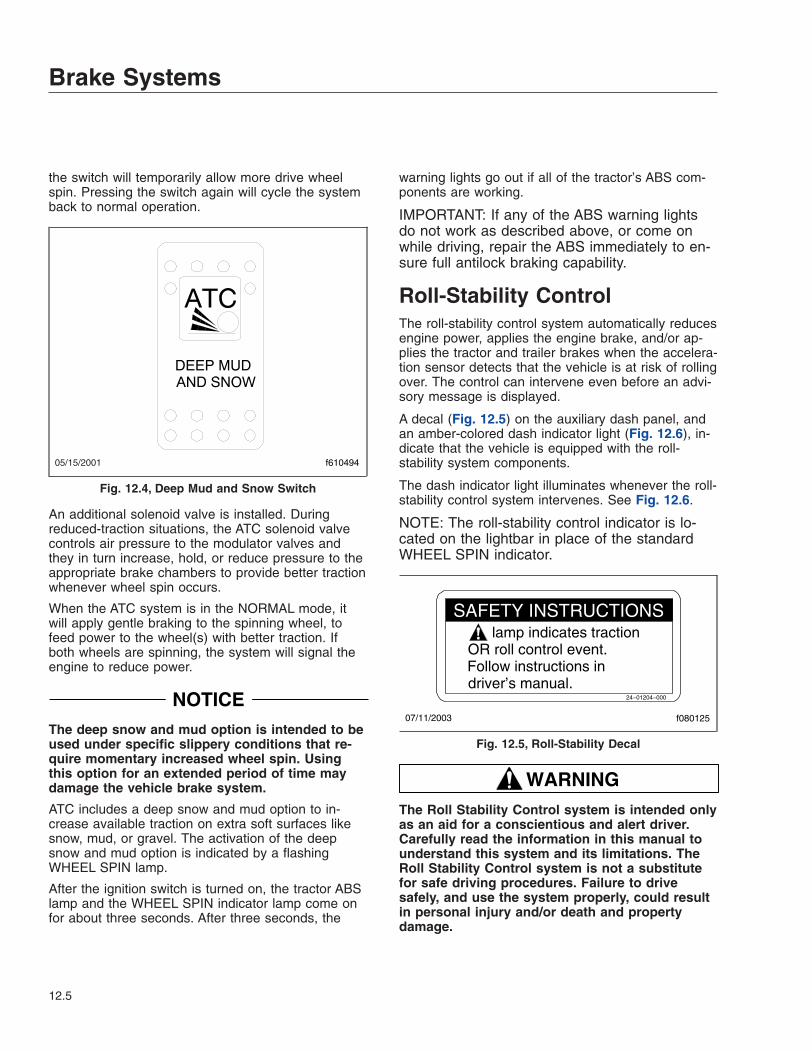
the switch will temporarily allow more drive wheelspin. Pressing the switch again will cycle the systemback to normal operation.
An additional solenoid valve is installed. Duringreduced-traction situations, the ATC solenoid valvecontrols air pressure to the modulator valves andthey in turn increase, hold, or reduce pressure to theappropriate brake chambers to provide better tractionwhenever wheel spin occurs.
When the ATC system is in the NORMAL mode, itwill apply gentle braking to the spinning wheel, tofeed power to the wheel(s) with better traction. Ifboth wheels are spinning, the system will signal theengine to reduce power.
NOTICEThe deep snow and mud option is intended to beused under specific slippery conditions that re-quire momentary increased wheel spin. Usingthis option for an extended period of time maydamage the vehicle brake system.
ATC includes a deep snow and mud option to in-crease available traction on extra soft surfaces likesnow, mud, or gravel. The activation of the deepsnow and mud option is indicated by a flashingWHEEL SPIN lamp.
After the ignition switch is turned on, the tractor ABSlamp and the WHEEL SPIN indicator lamp come onfor about three seconds. After three seconds, the
warning lights go out if all of the tractor’s ABS com-ponents are working.
IMPORTANT: If any of the ABS warning lightsdo not work as described above, or come onwhile driving, repair the ABS immediately to en-sure full antilock braking capability.
Roll-Stability ControlThe roll-stability control system automatically reducesengine power, applies the engine brake, and/or ap-plies the tractor and trailer brakes when the accelera-tion sensor detects that the vehicle is at risk of rollingover. The control can intervene even before an advi-sory message is displayed.
A decal (Fig. 12.5) on the auxiliary dash panel, andan amber-colored dash indicator light (Fig. 12.6), in-dicate that the vehicle is equipped with the roll-stability system components.
The dash indicator light illuminates whenever the roll-stability control system intervenes. See Fig. 12.6.
NOTE: The roll-stability control indicator is lo-cated on the lightbar in place of the standardWHEEL SPIN indicator.
WARNINGThe Roll Stability Control system is intended onlyas an aid for a conscientious and alert driver.Carefully read the information in this manual tounderstand this system and its limitations. TheRoll Stability Control system is not a substitutefor safe driving procedures. Failure to drivesafely, and use the system properly, could resultin personal injury and/or death and propertydamage.
05/15/2001 f610494
Fig. 12.4, Deep Mud and Snow Switch
lamp indicates tractionOR roll control event.Follow instructions indriver’s manual.
24−01204−000
07/11/2003 f080125
SAFETY INSTRUCTIONS
Fig. 12.5, Roll-Stability Decal
Brake Systems
12.5

06/26/2003 f602128
Fig. 12.6, Roll-Stability Indicator Lamp
Brake Systems
12.6
13
Steering SystemPower Steering System . . . . . . . . . . . . . . . . . . . . . . . . . . . . . . . . . . . . . . . . . . . . . . . . . . . . . . . . . . . 13.1
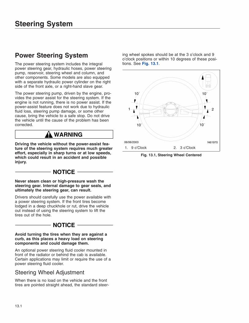
Power Steering SystemThe power steering system includes the integralpower steering gear, hydraulic hoses, power steeringpump, reservoir, steering wheel and column, andother components. Some models are also equippedwith a separate hydraulic power cylinder on the rightside of the front axle, or a right-hand slave gear.
The power steering pump, driven by the engine, pro-vides the power assist for the steering system. If theengine is not running, there is no power assist. If thepower-assist feature does not work due to hydraulicfluid loss, steering pump damage, or some othercause, bring the vehicle to a safe stop. Do not drivethe vehicle until the cause of the problem has beencorrected.
WARNINGDriving the vehicle without the power-assist fea-ture of the steering system requires much greatereffort, especially in sharp turns or at low speeds,which could result in an accident and possibleinjury.
NOTICENever steam clean or high-pressure wash thesteering gear. Internal damage to gear seals, andultimately the steering gear, can result.
Drivers should carefully use the power available witha power steering system. If the front tires becomelodged in a deep chuckhole or rut, drive the vehicleout instead of using the steering system to lift thetires out of the hole.
NOTICEAvoid turning the tires when they are against acurb, as this places a heavy load on steeringcomponents and could damage them.
An optional power steering fluid cooler mounted infront of the radiator or behind the cab is available.Certain applications may limit or require the use of apower steering fluid cooler.
Steering Wheel AdjustmentWhen there is no load on the vehicle and the fronttires are pointed straight ahead, the standard steer-
ing wheel spokes should be at the 3 o’clock and 9o’clock positions or within 10 degrees of these posi-tions. See Fig. 13.1.
06/06/2003 f461970
1 2
10
1010
10
1. 9 o’Clock 2. 3 o’Clock
Fig. 13.1, Steering Wheel Centered
Steering System
13.1

14
Manual Transmissions andClutch
Eaton® Fuller® Transmission Operation Tips . . . . . . . . . . . . . . . . . . . . . . . . . . . . . . . . . . . . . . . . . . 14.1Eaton Fuller Splitter and Range-Shift Transmissions . . . . . . . . . . . . . . . . . . . . . . . . . . . . . . . . . . . . 14.1Eaton Fuller Deep Reduction Transmissions . . . . . . . . . . . . . . . . . . . . . . . . . . . . . . . . . . . . . . . . . . 14.4Clutch . . . . . . . . . . . . . . . . . . . . . . . . . . . . . . . . . . . . . . . . . . . . . . . . . . . . . . . . . . . . . . . . . . . . . . . . . 14.7

Eaton® Fuller® TransmissionOperation TipsRefer to the Eaton website (www.roadranger.com)for additional information.
Follow these important operation principles:
• For all conditions, use the highest gear that isstill low enough to start the vehicle moving withthe engine at or near idle speed, and withoutslipping the clutch excessively.
When operating on-highway with no load orunder ideal conditions, use 1st gear to start thevehicle moving forward.
When operating off-road or under adverse con-ditions, use LOW gear to start the vehicle mov-ing forward.
• Use the clutch brake to stop gear rotationwhen shifting into LOW or reverse while thevehicle is stationary. The clutch brake is actu-ated by depressing the clutch pedal all the wayto the floor.
• Partially disengage the clutch to break enginetorque during normal gear shifts.
• Double-clutch between all upshifts and down-shifts that require movement of the shift knob.Splitting of gears does not require movementof the shift knob.
• Never push the range-preselection lever downinto low range while operating in high range,except when downshifting from 5th gear to 4thgear.
• Do not shift from high range to low range athigh vehicle speeds.
• Never make a range shift or a splitter shiftwhile the vehicle is in reverse.
• Never move the range-preselection lever withthe transmission in neutral while the vehicle ismoving.
• Skip ratios while shifting only when operatingconditions permit, depending on the load,grade, and road speed.
• Never coast with the transmission in neutral.
Eaton Fuller Splitter andRange-Shift TransmissionsCombination splitter and range-shift transmissionsallow the choice of two splitter ratios in each gear, aswell as the additional ratios provided by a low rangeand a high range.
General Information, Range-ShiftTransmissionsIMPORTANT: Not all ratios are used in eachrange, and the shift patterns vary betweentransmissions. Read the shift pattern decal onthe dash for the operating instructions for thetransmission installed in your vehicle.
The range-preselection lever selects the low or highrange for each transmission ratio. It is used onceduring an upshift sequence and once during a down-shift sequence.
To operate a range-shift transmission, move the gearshift lever through all the low-range gear positionsand then pull the range-preselection lever up tomove into the high-range ratios.
IMPORTANT: Always preselect range shiftswhen upshifting or downshifting. Preselectionrequires that the range lever be moved to thenecessary position before starting to shift. Pre-selecting range shifts prevents damage to thetransmission and provides for smoother shifts.
General Information, Splitter ControlDependent on the transmission model, some ratioscan be split using the splitter-control button (locatedon the side of the gear shift lever).
IMPORTANT: Always preselect splitter shifts.Preselection requires that the splitter-controlbutton be moved to the necessary position be-fore starting to shift. Preselecting splitter shiftsallows for smoother and faster shifting. Com-plete the shift immediately after preselecting thesplit to avoid unnecessary wear on transmissioncomponents.
Manual Transmissions and Clutch
14.1
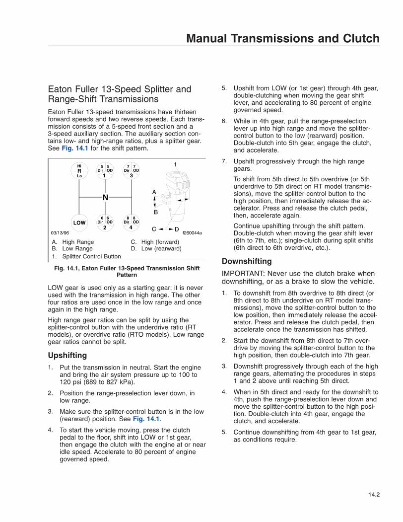
Eaton Fuller 13-Speed Splitter andRange-Shift TransmissionsEaton Fuller 13-speed transmissions have thirteenforward speeds and two reverse speeds. Each trans-mission consists of a 5-speed front section and a3-speed auxiliary section. The auxiliary section con-tains low- and high-range ratios, plus a splitter gear.See Fig. 14.1 for the shift pattern.
LOW gear is used only as a starting gear; it is neverused with the transmission in high range. The otherfour ratios are used once in the low range and onceagain in the high range.
High range gear ratios can be split by using thesplitter-control button with the underdrive ratio (RTmodels), or overdrive ratio (RTO models). Low rangegear ratios cannot be split.
Upshifting1. Put the transmission in neutral. Start the engine
and bring the air system pressure up to 100 to120 psi (689 to 827 kPa).
2. Position the range-preselection lever down, inlow range.
3. Make sure the splitter-control button is in the low(rearward) position. See Fig. 14.1.
4. To start the vehicle moving, press the clutchpedal to the floor, shift into LOW or 1st gear,then engage the clutch with the engine at or nearidle speed. Accelerate to 80 percent of enginegoverned speed.
5. Upshift from LOW (or 1st gear) through 4th gear,double-clutching when moving the gear shiftlever, and accelerating to 80 percent of enginegoverned speed.
6. While in 4th gear, pull the range-preselectionlever up into high range and move the splitter-control button to the low (rearward) position.Double-clutch into 5th gear, engage the clutch,and accelerate.
7. Upshift progressively through the high rangegears.
To shift from 5th direct to 5th overdrive (or 5thunderdrive to 5th direct on RT model transmis-sions), move the splitter-control button to thehigh position, then immediately release the ac-celerator. Press and release the clutch pedal,then, accelerate again.
Continue upshifting through the shift pattern.Double-clutch when moving the gear shift lever(6th to 7th, etc.); single-clutch during split shifts(6th direct to 6th overdrive, etc.).
Downshifting
IMPORTANT: Never use the clutch brake whendownshifting, or as a brake to slow the vehicle.
1. To downshift from 8th overdrive to 8th direct (or8th direct to 8th underdrive on RT model trans-missions), move the splitter-control button to thelow position, then immediately release the accel-erator. Press and release the clutch pedal, thenaccelerate once the transmission has shifted.
2. Start the downshift from 8th direct to 7th over-drive by moving the splitter-control button to thehigh position, then double-clutch into 7th gear.
3. Downshift progressively through each of the highrange gears, alternating the procedures in steps1 and 2 above until reaching 5th direct.
4. When in 5th direct and ready for the downshift to4th, push the range-preselection lever down andmove the splitter-control button to the high posi-tion. Double-clutch into 4th gear, engage theclutch, and accelerate.
5. Continue downshifting from 4th gear to 1st gear,as conditions require.
R1 3
2 4LOW
Dir OD5 5
Dir OD
Dir OD Dir OD
7 7
6 6 8 8
Hi
Lo
A
B
C D
1
03/13/96 f260044a
N
A. High RangeB. Low Range
C. High (forward)D. Low (rearward)
1. Splitter Control Button
Fig. 14.1, Eaton Fuller 13-Speed Transmission ShiftPattern
Manual Transmissions and Clutch
14.2

Eaton Fuller 18-Speed Splitter andRange-Shift TransmissionsEaton Fuller 18-speed transmissions have eighteenforward speeds and four reverse speeds. Each trans-mission consists of a 5-speed front section and a4-speed auxiliary section. The auxiliary section con-tains low- and high-range ratios, plus a splitter gear.See Fig. 14.2.
LOW gear in the front section is used only as a start-ing gear; it is never used when the transmission is inhigh range. LOW gear can be split, to provide both adirect and an overdrive ratio.
Upshifting1. Put the transmission in neutral. Start the engine
and bring the air system pressure up to 100 to120 psi (689 to 827 kPa).
2. Position the range-preselection lever down, inlow range and make sure the splitter-control but-ton is in the low position. See Fig. 14.2.
3. To start the vehicle moving, press the clutchpedal to the floor, shift into LOW, then engagethe clutch with the engine at or near idle speed.To shift from LOW direct to LOW overdrive,move the splitter-control button into the overdrive(forward) position, then immediately release theaccelerator. Press and release the clutch pedal,and accelerate.
4. Upshift from LOW overdrive to 1st direct by firstmoving the splitter-control button into the direct
drive (rearward) position (Fig. 14.2). Double-clutch into 1st gear.
Continue upshifting through the shift pattern.Double-clutch when moving the gear shift lever(1st to 2nd to 3rd to 4th); single-clutch duringsplit shifts (1st direct to 1st overdrive, etc.).
5. When in 4th overdrive, use the range-preselection lever and the splitter-control buttonto upshift to 5th gear.
While in 4th gear, pull the range-preselectionlever up into high range and move the splitter-control button to the low position. Double-clutchinto 5th gear, engage the clutch, and accelerate.
6. Upshift progressively through the high rangegears.
To shift from 5th direct to 5th overdrive (or 5thunderdrive to 5th direct on RT model transmis-sions), move the splitter-control button to thehigh position, then immediately release the ac-celerator. Press and release the clutch pedal,and accelerate.
Continue upshifting through the shift pattern.Double-clutch when moving the gear shift lever(6th to 7th, etc.); single-clutch during split shifts(6th direct to 6th overdrive, etc.).
Downshifting
IMPORTANT: Never use the clutch brake whendownshifting, or as a brake to slow the vehicle.
1. To downshift from 8th overdrive to 8th direct (or8th direct to 8th underdrive on RT model trans-missions), move the splitter-control button to thelow position, then immediately release the accel-erator. Press and release the clutch pedal, thenaccelerate once the transmission has shifted.
2. Start the downshift from 8th direct to 7th over-drive by moving the splitter-control button to thehigh position, then immediately double-clutch into7th gear.
3. Downshift progressively through each of the highrange gears, alternating the procedures in steps1 and 2 above until reaching 5th direct.
4. When in 4th overdrive, push the range-preselection lever down and move the splitter-control button to the high position. Double-clutch
N
R 1Dir
5Dir
5OD1
OD3
Dir
7Dir
7OD3
OD
2Dir
6Dir
6OD2
OD4
Dir
8Dir
8OD4
ODLOWDir
LOWOD
A
B
C D
1
03/13/96 f260157a
A. High RangeB. Low Range
C. Overdrive (forward)D. Direct Drive (rearward)
1. Splitter Control Button
Fig. 14.2, Eaton Fuller 18-Speed Transmission ShiftPattern
Manual Transmissions and Clutch
14.3
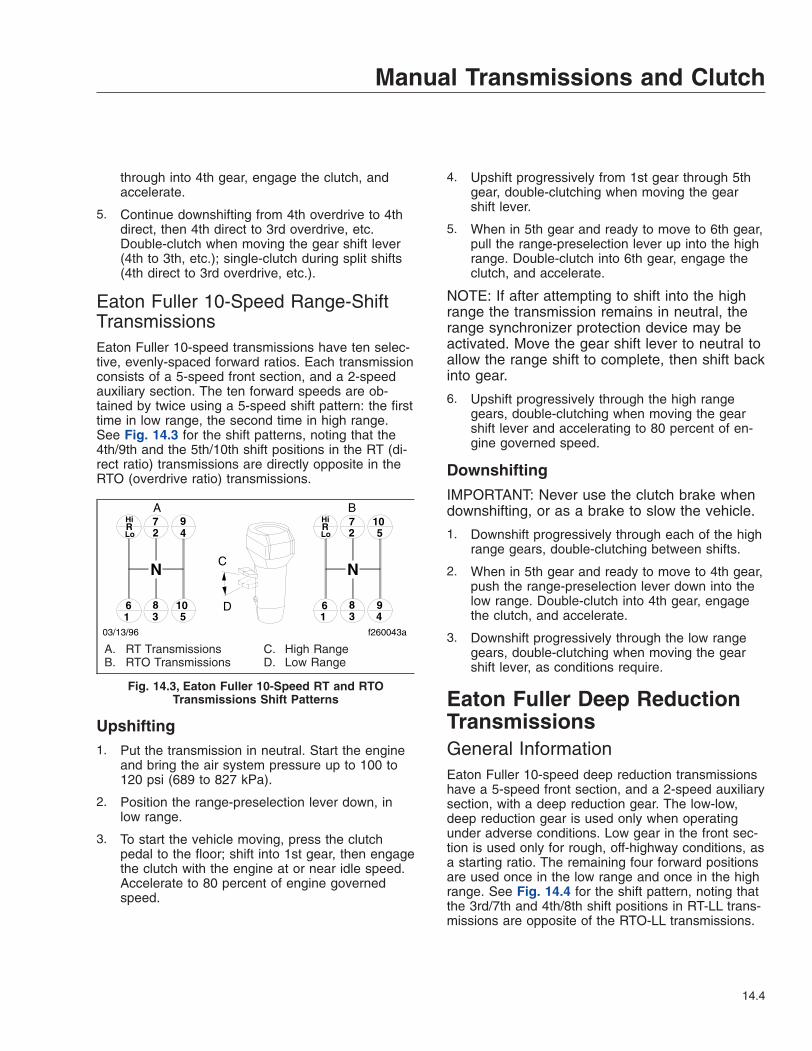
through into 4th gear, engage the clutch, andaccelerate.
5. Continue downshifting from 4th overdrive to 4thdirect, then 4th direct to 3rd overdrive, etc.Double-clutch when moving the gear shift lever(4th to 3th, etc.); single-clutch during split shifts(4th direct to 3rd overdrive, etc.).
Eaton Fuller 10-Speed Range-ShiftTransmissionsEaton Fuller 10-speed transmissions have ten selec-tive, evenly-spaced forward ratios. Each transmissionconsists of a 5-speed front section, and a 2-speedauxiliary section. The ten forward speeds are ob-tained by twice using a 5-speed shift pattern: the firsttime in low range, the second time in high range.See Fig. 14.3 for the shift patterns, noting that the4th/9th and the 5th/10th shift positions in the RT (di-rect ratio) transmissions are directly opposite in theRTO (overdrive ratio) transmissions.
Upshifting1. Put the transmission in neutral. Start the engine
and bring the air system pressure up to 100 to120 psi (689 to 827 kPa).
2. Position the range-preselection lever down, inlow range.
3. To start the vehicle moving, press the clutchpedal to the floor; shift into 1st gear, then engagethe clutch with the engine at or near idle speed.Accelerate to 80 percent of engine governedspeed.
4. Upshift progressively from 1st gear through 5thgear, double-clutching when moving the gearshift lever.
5. When in 5th gear and ready to move to 6th gear,pull the range-preselection lever up into the highrange. Double-clutch into 6th gear, engage theclutch, and accelerate.
NOTE: If after attempting to shift into the highrange the transmission remains in neutral, therange synchronizer protection device may beactivated. Move the gear shift lever to neutral toallow the range shift to complete, then shift backinto gear.
6. Upshift progressively through the high rangegears, double-clutching when moving the gearshift lever and accelerating to 80 percent of en-gine governed speed.
Downshifting
IMPORTANT: Never use the clutch brake whendownshifting, or as a brake to slow the vehicle.
1. Downshift progressively through each of the highrange gears, double-clutching between shifts.
2. When in 5th gear and ready to move to 4th gear,push the range-preselection lever down into thelow range. Double-clutch into 4th gear, engagethe clutch, and accelerate.
3. Downshift progressively through the low rangegears, double-clutching when moving the gearshift lever, as conditions require.
Eaton Fuller Deep ReductionTransmissionsGeneral InformationEaton Fuller 10-speed deep reduction transmissionshave a 5-speed front section, and a 2-speed auxiliarysection, with a deep reduction gear. The low-low,deep reduction gear is used only when operatingunder adverse conditions. Low gear in the front sec-tion is used only for rough, off-highway conditions, asa starting ratio. The remaining four forward positionsare used once in the low range and once in the highrange. See Fig. 14.4 for the shift pattern, noting thatthe 3rd/7th and 4th/8th shift positions in RT-LL trans-missions are opposite of the RTO-LL transmissions.
4
N
72
9
61
83
105
72
105
61
83
94
RHi
LoRHi
Lo
A B
C
D
03/13/96 f260043a
N
A. RT TransmissionsB. RTO Transmissions
C. High RangeD. Low Range
Fig. 14.3, Eaton Fuller 10-Speed RT and RTOTransmissions Shift Patterns
Manual Transmissions and Clutch
14.4
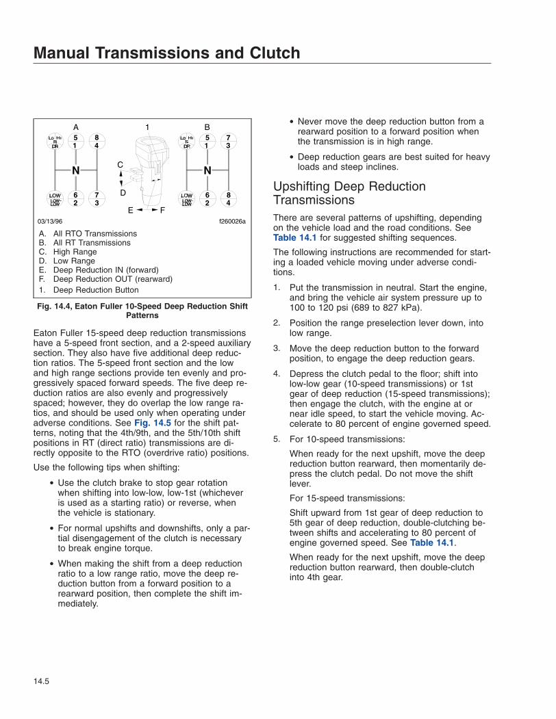
Eaton Fuller 15-speed deep reduction transmissionshave a 5-speed front section, and a 2-speed auxiliarysection. They also have five additional deep reduc-tion ratios. The 5-speed front section and the lowand high range sections provide ten evenly and pro-gressively spaced forward speeds. The five deep re-duction ratios are also evenly and progressivelyspaced; however, they do overlap the low range ra-tios, and should be used only when operating underadverse conditions. See Fig. 14.5 for the shift pat-terns, noting that the 4th/9th, and the 5th/10th shiftpositions in RT (direct ratio) transmissions are di-rectly opposite to the RTO (overdrive ratio) positions.
Use the following tips when shifting:
• Use the clutch brake to stop gear rotationwhen shifting into low-low, low-1st (whicheveris used as a starting ratio) or reverse, whenthe vehicle is stationary.
• For normal upshifts and downshifts, only a par-tial disengagement of the clutch is necessaryto break engine torque.
• When making the shift from a deep reductionratio to a low range ratio, move the deep re-duction button from a forward position to arearward position, then complete the shift im-mediately.
• Never move the deep reduction button from arearward position to a forward position whenthe transmission is in high range.
• Deep reduction gears are best suited for heavyloads and steep inclines.
Upshifting Deep ReductionTransmissionsThere are several patterns of upshifting, dependingon the vehicle load and the road conditions. SeeTable 14.1 for suggested shifting sequences.
The following instructions are recommended for start-ing a loaded vehicle moving under adverse condi-tions.
1. Put the transmission in neutral. Start the engine,and bring the vehicle air system pressure up to100 to 120 psi (689 to 827 kPa).
2. Position the range preselection lever down, intolow range.
3. Move the deep reduction button to the forwardposition, to engage the deep reduction gears.
4. Depress the clutch pedal to the floor; shift intolow-low gear (10-speed transmissions) or 1stgear of deep reduction (15-speed transmissions);then engage the clutch, with the engine at ornear idle speed, to start the vehicle moving. Ac-celerate to 80 percent of engine governed speed.
5. For 10-speed transmissions:
When ready for the next upshift, move the deepreduction button rearward, then momentarily de-press the clutch pedal. Do not move the shiftlever.
For 15-speed transmissions:
Shift upward from 1st gear of deep reduction to5th gear of deep reduction, double-clutching be-tween shifts and accelerating to 80 percent ofengine governed speed. See Table 14.1.
When ready for the next upshift, move the deepreduction button rearward, then double-clutchinto 4th gear.
1 45 8
6 732
1 35 7
26 8
4
A B
C
D
E F
1
03/13/96 f260026a
N N
A. All RTO TransmissionsB. All RT TransmissionsC. High RangeD. Low RangeE. Deep Reduction IN (forward)F. Deep Reduction OUT (rearward)1. Deep Reduction Button
Fig. 14.4, Eaton Fuller 10-Speed Deep Reduction ShiftPatterns
Manual Transmissions and Clutch
14.5
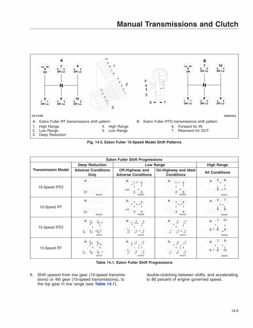
Eaton Fuller Shift Progressions
Transmission ModelDeep Reduction Low Range High Range
Adverse ConditionsOnly
Off-Highway andAdverse Conditions
On-Highway and IdealConditions
All Conditions
10-Speed RTO
R
f260335
LOW−LOW
R 1
2 3
4
LOW
f260333
R 1
2 3
4
f260336
R
6 7
f260337
5 8
10-Speed RT
R
f260335
LOW−LOW
R 1
2 4
3
f260338
LOW
R 1
2 4
3
f260339
R
6 8
f260340
5 7
15-Speed RTO
f260341
R
2 5
31DRDRDR
DR DR
4
f260342
R
LoLo Lo
LoLo
1
2
4
5
3
f260343
R
1
2
3 4
5
Lo
LoLo
LoLo
R
6
7
8 9
10
f260344
15-Speed RT
f260345
R
DR DR
DRDRDR1
2
3
4
5
f260346
R
Lo Lo Lo
LoLo42
3 51
f260347
R
Lo Lo Lo
LoLo2
3 5
4
1
R
6
7
8 10
f260348
6
Table 14.1, Eaton Fuller Shift Progressions
6. Shift upward from low gear (10-speed transmis-sions) or 4th gear (15-speed transmissions), tothe top gear in low range (see Table 14.1),
double-clutching between shifts, and acceleratingto 80 percent of engine governed speed.
7 9
6 8 10
7 10
6 8 9
R Lo Hi
DR DR Lo 2 2
DR Lo
DR Lo DR Lo DR Lo
4 4
1 1 3 3 5 5
R Lo Hi
DR DR Lo DR Lo
DR Lo DR Lo DR Lo
2 2 5 5
1 1 3 3 4 4
1
1
2
2
3
3
4
4
5
5
6 7
8 9
10
1
2
3
4
5
6 7
03/13/96 f260045a
N N
A B
A. Eaton Fuller RT transmissions shift pattern B. Eaton Fuller RTO transmissions shift pattern1. High Range2. Low Range3. Deep Reduction
4. High Range5. Low Range
6. Forward for IN7. Rearward for OUT
Fig. 14.5, Eaton Fuller 15-Speed Model Shift Patterns
Manual Transmissions and Clutch
14.6
7. While in the top gear of the low-range shift pat-tern, flip the range preselection lever up. Double-clutch into the bottom gear in high range (seeTable 14.1).
8. With the transmission in high range, shift pro-gressively upward through each of the highrange gears (see Table 14.1), double-clutchingbetween shifts.
Downshifting Deep ReductionTransmissions1. With the transmission in high range, shift pro-
gressively downward to the bottom gear in highrange, double-clutching between shifts.
2. When in the bottom gear of the high-range shiftpattern, push the range preselection lever down.Double-clutch into the top gear of the low-rangeshift pattern.
IMPORTANT: Never move the deep reductionbutton to a forward position when the transmis-sion is in high range.
3. With the transmission in low range, downshiftthrough the low range gears, as conditions re-quire.
ClutchClutch General InformationTo ensure long service life of the clutch, start in theright gear, be alert to clutch malfunctions, and knowwhen to adjust the clutch.
Typical operation will not break down the clutch fric-tion surfaces. Heat and wear are almost nonexistentwhen a clutch is fully engaged. However, during themoment of engagement, when the clutch is pickingup the load, considerable heat is generated. If aclutch slips excessively, high temperatures developquickly between the flywheel, driven discs, and pres-sure plates. An improperly adjusted or slipping clutchcan generate temperatures high enough to destroythe clutch.
Clutch OperationClutch Break-InThe clutch may slip for a short time while the frictionsurfaces break-in on a new or newly-installed clutch.
NOTICEDo not allow the clutch to slip longer than twoseconds. Clutch slippage for longer than twoseconds may severely damage the clutch disc,pressure plate, or flywheel. Damage caused byclutch slippage due to improper break-in is notwarrantable.
During initial operation of a new vehicle or a vehiclewith a new clutch, check for clutch slippage duringacceleration. If the clutch slips, decelerate until theclutch does not slip. Allow the clutch to cool 15 to 30seconds, then gradually accelerate again. If theclutch continues to slip, repeat the procedure asmany as five times. If the clutch slips after five at-tempts, stop the vehicle and allow the clutch to coolfor at least one hour. Notify your Western Star dealerof the problem.
Moving the Vehicle in the Proper GearAn empty vehicle can be started in a higher gearthan can a partially- or fully-loaded vehicle. Selectthe gear combination that allows the vehicle to startmoving with an idling engine or, if necessary, justenough throttle to prevent stalling the engine.
Gear Shifting TechniquesUpshift into a higher gear only when the vehiclespeed allows the transmission input shaft speed tomatch the flywheel speed when engaging the clutch.This technique results in the smallest speed differ-ence between the clutch disc and the flywheel, andcauses the least heat and wear on the clutch assem-bly. When downshifting, increase the input shaftspeed to match the flywheel by slightly revving theengine.
Vehicle LoadingClutches are designed for specific vehicle applica-tions and loads.
NOTICEExceeding vehicle load limits can result in dam-age to the clutch and the entire powertrain.
Manual Transmissions and Clutch
14.7
Clutch BrakeApply the clutch brake by depressing the clutchpedal all the way to the floor plate. The last part ofpedal travel will compress the clutch brake platestogether, stopping the transmission input shaft. Theclutch brake stops the transmission gears from rotat-ing in order to quickly engage a transmission gearafter idling in neutral.
NOTICENever apply the clutch brake when making down-shifts or upshifts. If the clutch brake is appliedwhen the vehicle is moving, the clutch brake willtry to stop or decelerate the vehicle, causingrapid wear of the clutch brake friction discs. Con-siderable heat will be generated, causing damageto the release bearings and the transmissionfront bearings.
Using the ClutchUse the clutch pedal only when starting the engine,launching the vehicle from a stop, or shifting. Tolaunch a stationary vehicle, depress the clutch pedalall the way to the floor plate (see Clutch Brakeabove) and shift from neutral to a low gear. Slowlyraise your foot until the clutch starts to engage. Inthis position the clutch is starting to connect thetransmission input shaft to the flywheel and is caus-ing the most heat and wear. Slightly increase the en-gine speed and smoothly allow the clutch pedal toreturn to the rest position. Do not allow the clutch toremain in the partially-engaged position any longerthan necessary to obtain a smooth start.
Double-clutch to shift gears while the vehicle is mov-ing. Depress the clutch pedal most of the way in, butnot all the way to the floor plate. Depressing theclutch pedal to the floor plate will engage the clutchbrake. Shift the transmission into neutral and fullyrelease the clutch pedal. When upshifting, wait forthe engine speed to decrease to the road speed.When downshifting, increase the engine speed tomatch the road speed. Fully release the clutch pedalafter completing the shift.
NOTICERiding the clutch while driving is damaging tothe clutch because partial clutch engagementcauses slippage and heat. Resting your foot on
the clutch pedal will also put a constant thrustload on the release bearing, thinning the bearinglubricant and increasing the wear on the bearing.
Holding the Vehicle On an InclineAlways use the vehicle service brakes to prevent thevehicle from rolling backwards while stopped on ahill. Slipping the clutch on a hill to maintain vehicleposition will quickly damage the clutch assembly.
CoastingCoasting with the clutch pedal depressed and thetransmission in a low gear can cause high drivendisc speed. The clutch speed can be much higherunder these conditions than when the engine is driv-ing the clutch. This condition creates a hazardoussituation due to the lack of vehicle control and due tothe high clutch disc speed. Engaging the clutchunder these conditions can cause component dam-age because of the shock loads to the clutch anddrivetrain.
WARNINGAlways shift into the gear that is correct for thetraveling speed of the vehicle and engage theclutch. Coasting with the clutch disengaged canprevent engagement of the correct transmissiongear which can cause loss of vehicle control,possibly resulting in personal injury or propertydamage.
High clutch disc speeds while coasting can alsocause the clutch facing to be thrown off the disc.Flying debris from the clutch can cause injury topersons in the cab.
Clutch MaintenanceChecking the Clutch AdjustmentReport erratic clutch operation as soon as possible togive maintenance personnel a chance to inspect, lu-bricate, and adjust the clutch components. Noticeany gradual decrease in the distance the clutchpedal moves before resistance is felt.
NOTICEOperating the vehicle with incorrect free pedalcould result in clutch damage.
Manual Transmissions and Clutch
14.8
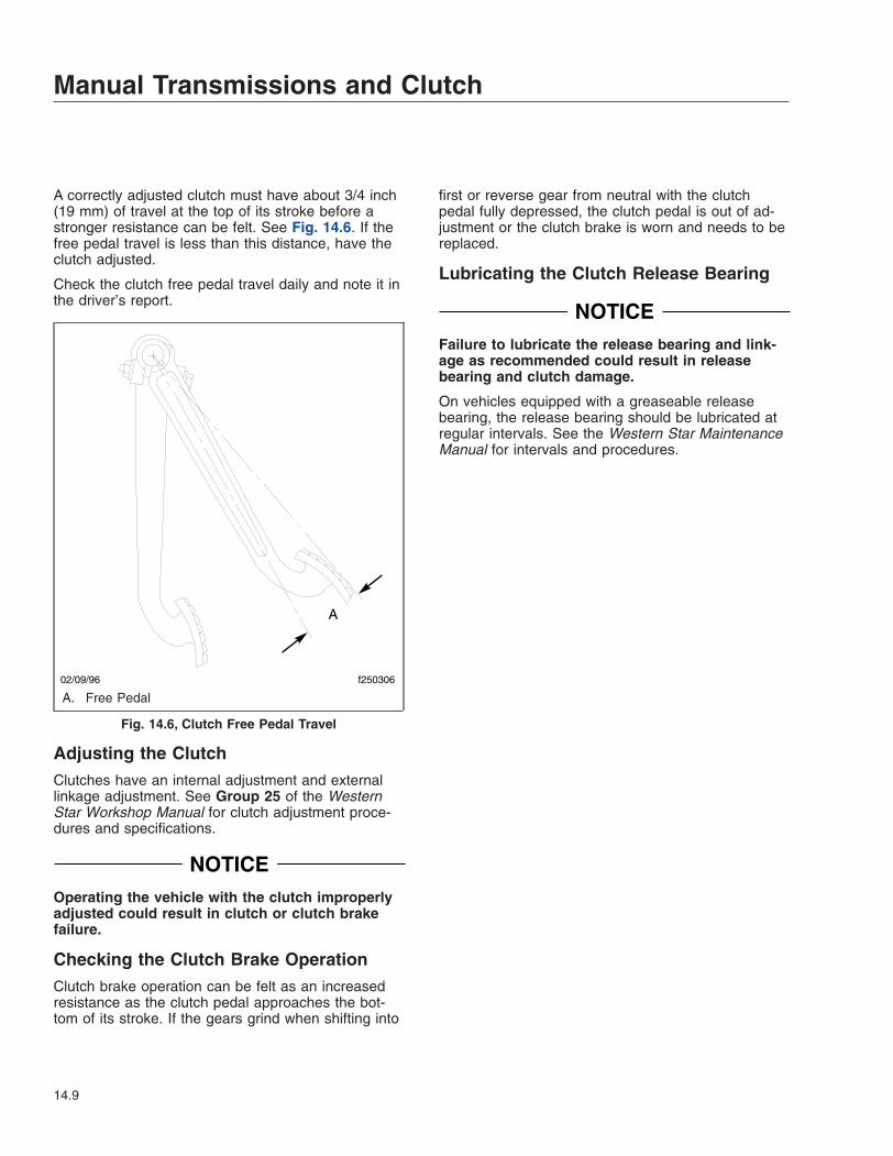
A correctly adjusted clutch must have about 3/4 inch(19 mm) of travel at the top of its stroke before astronger resistance can be felt. See Fig. 14.6. If thefree pedal travel is less than this distance, have theclutch adjusted.
Check the clutch free pedal travel daily and note it inthe driver’s report.
Adjusting the ClutchClutches have an internal adjustment and externallinkage adjustment. See Group 25 of the WesternStar Workshop Manual for clutch adjustment proce-dures and specifications.
NOTICEOperating the vehicle with the clutch improperlyadjusted could result in clutch or clutch brakefailure.
Checking the Clutch Brake OperationClutch brake operation can be felt as an increasedresistance as the clutch pedal approaches the bot-tom of its stroke. If the gears grind when shifting into
first or reverse gear from neutral with the clutchpedal fully depressed, the clutch pedal is out of ad-justment or the clutch brake is worn and needs to bereplaced.
Lubricating the Clutch Release Bearing
NOTICEFailure to lubricate the release bearing and link-age as recommended could result in releasebearing and clutch damage.
On vehicles equipped with a greaseable releasebearing, the release bearing should be lubricated atregular intervals. See the Western Star MaintenanceManual for intervals and procedures.
02/09/96 f250306
A. Free Pedal
Fig. 14.6, Clutch Free Pedal Travel
Manual Transmissions and Clutch
14.9

15
Automated and AutomaticTransmissions
Eaton® Fuller® Automated Transmissions . . . . . . . . . . . . . . . . . . . . . . . . . . . . . . . . . . . . . . . . . . . . 15.1Allison Automatic Transmissions . . . . . . . . . . . . . . . . . . . . . . . . . . . . . . . . . . . . . . . . . . . . . . . . . . . . 15.5
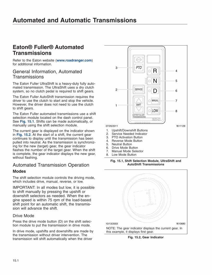
Eaton® Fuller® AutomatedTransmissionsRefer to the Eaton website (www.roadranger.com)for additional information.
General Information, AutomatedTransmissionsThe Eaton Fuller UltraShift is a heavy-duty fully auto-mated transmission. The UltraShift uses a dry clutchsystem, so no clutch pedal is required to shift gears.
The Eaton Fuller AutoShift transmission requires thedriver to use the clutch to start and stop the vehicle.However, the driver does not need to use the clutchto shift gears.
The Eaton Fuller automated transmissions use a shiftselection module located on the dash control panel.See Fig. 15.1. Shifts can be made automatically, ormanually using the shift selection module.
The current gear is displayed on the indicator shownin Fig. 15.2. At the start of a shift, the current gearcontinues to display until the transmission has beenpulled into neutral. As the transmission is synchroniz-ing for the new (target) gear, the gear indicatorflashes the number of the target gear. When the shiftis complete, the gear indicator displays the new gear,without flashing.
Automated Transmission OperationModesThe shift selection module controls the driving mode,which includes drive, manual, reverse, or low.
IMPORTANT: In all modes but low, it is possibleto shift manually by pressing the upshift ordownshift selectors as needed. When the en-gine speed is within 75 rpm of the load-basedshift point for an automatic shift, the transmis-sion will advance the shift.
Drive ModePress the drive mode button (D) on the shift selec-tion module to put the transmission in drive mode.
In drive mode, upshifts and downshifts are made bythe transmission without driver intervention. Thetransmission will shift automatically when the driver
SERVICE
SHIFT
MANUAL
EATON FULLERTRANSMISSIONS
LOW
D
N
RPTO
07/20/2011 f611129
1
4
2
3
5
6
7
8
1. Upshift/Downshift Buttons2. Service Needed Indicator3. PTO Activation Button4. Reverse Mode Button5. Neutral Button6. Drive Mode Button7. Manual Mode Selector8. Low Mode Button
Fig. 15.1, Shift Selection Module, UltraShift andAutoShift Transmissions
10/13/2003 f610680
NOTE: The gear indicator displays the current gear. Inthis example, it displays first gear.
Fig. 15.2, Gear Indicator
Automated and Automatic Transmissions
15.1
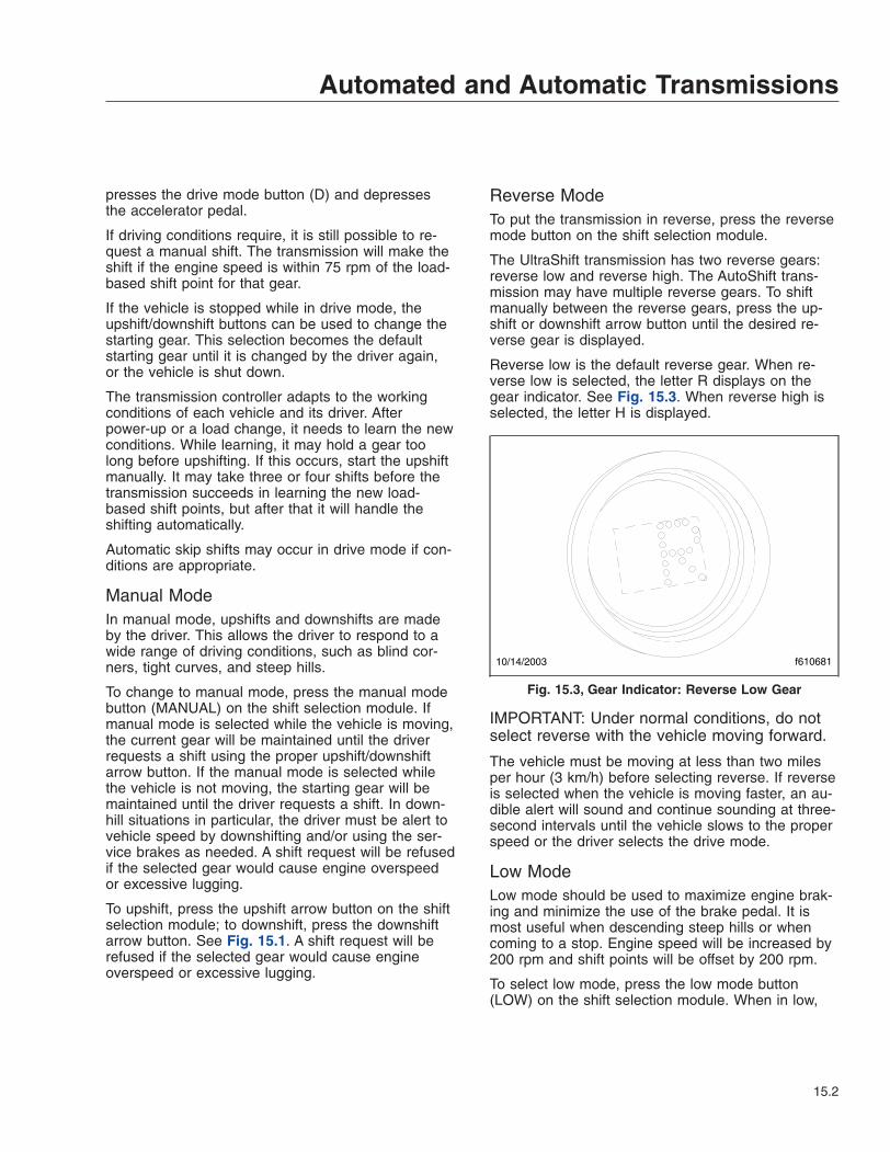
presses the drive mode button (D) and depressesthe accelerator pedal.
If driving conditions require, it is still possible to re-quest a manual shift. The transmission will make theshift if the engine speed is within 75 rpm of the load-based shift point for that gear.
If the vehicle is stopped while in drive mode, theupshift/downshift buttons can be used to change thestarting gear. This selection becomes the defaultstarting gear until it is changed by the driver again,or the vehicle is shut down.
The transmission controller adapts to the workingconditions of each vehicle and its driver. Afterpower-up or a load change, it needs to learn the newconditions. While learning, it may hold a gear toolong before upshifting. If this occurs, start the upshiftmanually. It may take three or four shifts before thetransmission succeeds in learning the new load-based shift points, but after that it will handle theshifting automatically.
Automatic skip shifts may occur in drive mode if con-ditions are appropriate.
Manual ModeIn manual mode, upshifts and downshifts are madeby the driver. This allows the driver to respond to awide range of driving conditions, such as blind cor-ners, tight curves, and steep hills.
To change to manual mode, press the manual modebutton (MANUAL) on the shift selection module. Ifmanual mode is selected while the vehicle is moving,the current gear will be maintained until the driverrequests a shift using the proper upshift/downshiftarrow button. If the manual mode is selected whilethe vehicle is not moving, the starting gear will bemaintained until the driver requests a shift. In down-hill situations in particular, the driver must be alert tovehicle speed by downshifting and/or using the ser-vice brakes as needed. A shift request will be refusedif the selected gear would cause engine overspeedor excessive lugging.
To upshift, press the upshift arrow button on the shiftselection module; to downshift, press the downshiftarrow button. See Fig. 15.1. A shift request will berefused if the selected gear would cause engineoverspeed or excessive lugging.
Reverse ModeTo put the transmission in reverse, press the reversemode button on the shift selection module.
The UltraShift transmission has two reverse gears:reverse low and reverse high. The AutoShift trans-mission may have multiple reverse gears. To shiftmanually between the reverse gears, press the up-shift or downshift arrow button until the desired re-verse gear is displayed.
Reverse low is the default reverse gear. When re-verse low is selected, the letter R displays on thegear indicator. See Fig. 15.3. When reverse high isselected, the letter H is displayed.
IMPORTANT: Under normal conditions, do notselect reverse with the vehicle moving forward.
The vehicle must be moving at less than two milesper hour (3 km/h) before selecting reverse. If reverseis selected when the vehicle is moving faster, an au-dible alert will sound and continue sounding at three-second intervals until the vehicle slows to the properspeed or the driver selects the drive mode.
Low ModeLow mode should be used to maximize engine brak-ing and minimize the use of the brake pedal. It ismost useful when descending steep hills or whencoming to a stop. Engine speed will be increased by200 rpm and shift points will be offset by 200 rpm.
To select low mode, press the low mode button(LOW) on the shift selection module. When in low,
10/14/2003 f610681
Fig. 15.3, Gear Indicator: Reverse Low Gear
Automated and Automatic Transmissions
15.2
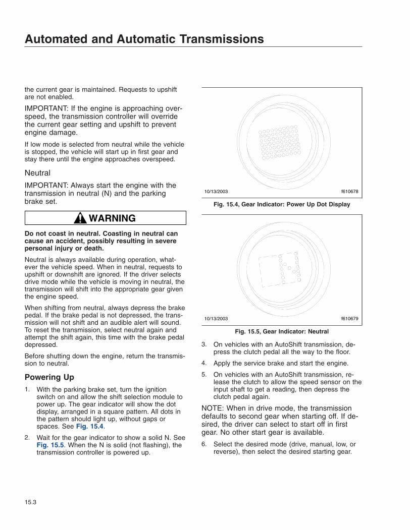
the current gear is maintained. Requests to upshiftare not enabled.
IMPORTANT: If the engine is approaching over-speed, the transmission controller will overridethe current gear setting and upshift to preventengine damage.
If low mode is selected from neutral while the vehicleis stopped, the vehicle will start up in first gear andstay there until the engine approaches overspeed.
Neutral
IMPORTANT: Always start the engine with thetransmission in neutral (N) and the parkingbrake set.
WARNINGDo not coast in neutral. Coasting in neutral cancause an accident, possibly resulting in severepersonal injury or death.
Neutral is always available during operation, what-ever the vehicle speed. When in neutral, requests toupshift or downshift are ignored. If the driver selectsdrive mode while the vehicle is moving in neutral, thetransmission will shift into the appropriate gear giventhe engine speed.
When shifting from neutral, always depress the brakepedal. If the brake pedal is not depressed, the trans-mission will not shift and an audible alert will sound.To reset the transmission, select neutral again andattempt the shift again, this time with the brake pedaldepressed.
Before shutting down the engine, return the transmis-sion to neutral.
Powering Up1. With the parking brake set, turn the ignition
switch on and allow the shift selection module topower up. The gear indicator will show the dotdisplay, arranged in a square pattern. All dots inthe pattern should light up, without gaps orspaces. See Fig. 15.4.
2. Wait for the gear indicator to show a solid N. SeeFig. 15.5. When the N is solid (not flashing), thetransmission controller is powered up.
3. On vehicles with an AutoShift transmission, de-press the clutch pedal all the way to the floor.
4. Apply the service brake and start the engine.
5. On vehicles with an AutoShift transmission, re-lease the clutch to allow the speed sensor on theinput shaft to get a reading, then depress theclutch pedal again.
NOTE: When in drive mode, the transmissiondefaults to second gear when starting off. If de-sired, the driver can select to start off in firstgear. No other start gear is available.
6. Select the desired mode (drive, manual, low, orreverse), then select the desired starting gear.
10/13/2003 f610678
Fig. 15.4, Gear Indicator: Power Up Dot Display
10/13/2003 f610679
Fig. 15.5, Gear Indicator: Neutral
Automated and Automatic Transmissions
15.3

WARNINGWhen starting or stopping on hills and grades,use extra care to prevent the vehicle from rollingback. A rollback accident could cause death, seri-ous personal injury, or property damage.
7. On a level grade, release the parking and ser-vice brakes.
8. Move the vehicle forward by doing one of thefollowing:
• Vehicles with an UltraShift transmission:depress the accelerator pedal.
• Vehicles with an AutoShift transmission:release the clutch and depress the accel-erator pedal.
Powering Down1. On vehicles equipped with an Autoshift transmis-
sion, depress the clutch pedal to the floor.
2. Bring the vehicle to a halt
3. Apply the service brakes.
4. Select neutral (N) on the shift selection module.When the N on the gear indicator is solid (notflashing), the transmission controller is ready topower down.
5. Set the parking brake and shut down the engine.
UpshiftingTo request an upshift, push the upshift arrow buttonon the shift selection module. If the gear is available,the transmission will upshift and the new gear willdisplay on the gear indicator. If the gear requested isunavailable, a tone will sound.
Upshifts are not available in low mode, except to pre-vent engine overspeed.
NOTE: The AutoShift transmission is able toperform triple upshifts when the next threehigher gears are available and conditions areappropriate.
Skip shifts can be performed only in manual mode.To skip shift, press the upshift button twice or threetimes. The number of the gear engaged will appearon the gear indicator.
DownshiftingTo request a downshift, push the downshift arrowbutton on the shift selection module. If the gear isavailable, the transmission will downshift and thenew gear will display on the gear indicator. If thegear requested is unavailable, a tone will sound.
Before starting down a hill, downshift to a speed thatyou can control without hard pressure on the servicebrakes. Before entering a curve, downshift if neces-sary. This lets you use some power through thecurve to help the vehicle be more stable in the turn.It also allows you to regain speed faster as youcome out of the curve.
NOTE: The AutoShift transmission is able toperform triple downshifts when the next threelower gears are available and conditions areappropriate.
Skip shifts can be performed only in manual mode.To skip shift, press the downshift button twice orthree times. The number of the gear engaged willappear on the gear indicator.
For best engine braking, select low mode while mov-ing. In low, downshifts are performed at higher rpmthan in drive.
IMPORTANT: If the engine is approaching over-speed, the transmission controller will overridethe current gear setting and upshift to preventengine damage.
Transmission DiagnosticsClutch Protection Fault, UltraShiftTransmissionsEven though a vehicle with an UltraShift transmissiondoes not have a clutch pedal, it does have a me-chanical clutch. As you slowly increase and decreaseengine rpm from a stop, the mechanical clutch is en-gaging and disengaging, just like slipping the clutchwith a manual transmission. Excessive clutch slip-page creates heat and reduces the life of the clutch.Conditions that can cause clutch damage include:
• Using the accelerator pedal to hold the vehicleon a hill
• Starting the vehicle from a stop in a gear that’stoo high
• Overloading the vehicle
Automated and Automatic Transmissions
15.4
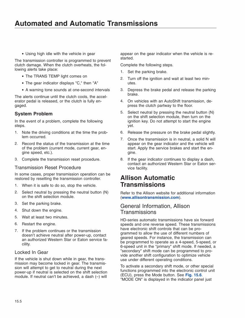
• Using high idle with the vehicle in gear
The transmission controller is programmed to preventclutch damage. When the clutch overheats, the fol-lowing alerts take place:
• The TRANS TEMP light comes on
• The gear indicator displays "C," then "A"
• A warning tone sounds at one-second intervals
The alerts continue until the clutch cools, the accel-erator pedal is released, or the clutch is fully en-gaged.
System ProblemIn the event of a problem, complete the followingsteps.
1. Note the driving conditions at the time the prob-lem occurred.
2. Record the status of the transmission at the timeof the problem (current mode, current gear, en-gine speed, etc.).
3. Complete the transmission reset procedure.
Transmission Reset ProcedureIn some cases, proper transmission operation can berestored by resetting the transmission controller.
1. When it is safe to do so, stop the vehicle.
2. Select neutral by pressing the neutral button (N)on the shift selection module.
3. Set the parking brake.
4. Shut down the engine.
5. Wait at least two minutes.
6. Restart the engine.
7. If the problem continues or the transmissiondoesn’t achieve neutral after power-up, contactan authorized Western Star or Eaton service fa-cility.
Locked In GearIf the vehicle is shut down while in gear, the trans-mission may become locked in gear. The transmis-sion will attempt to get to neutral during the nextpower-up if neutral is selected on the shift selectionmodule. If neutral can’t be achieved, a dash (–) will
appear on the gear indicator when the vehicle is re-started.
Complete the following steps.
1. Set the parking brake.
2. Turn off the ignition and wait at least two min-utes.
3. Depress the brake pedal and release the parkingbrake.
4. On vehicles with an AutoShift transmission, de-press the clutch partway to the floor.
5. Select neutral by pressing the neutral button (N)on the shift selection module, then turn on theignition key. Do not attempt to start the engineyet.
6. Release the pressure on the brake pedal slightly.
7. Once the transmission is in neutral, a solid N willappear on the gear indicator and the vehicle willstart. Apply the service brakes and start the en-gine.
8. If the gear indicator continues to display a dash,contact an authorized Western Star or Eaton ser-vice facility.
Allison AutomaticTransmissionsRefer to the Allison website for additional information(www.allisontransmission.com).
General Information, AllisonTransmissionsHD-series automatic transmissions have six forwardspeeds and one reverse speed. These transmissionshave electronic shift controls that can be pro-grammed to allow the use of different numbers ofgeared speeds. For instance, the transmission canbe programmed to operate as a 4-speed, 5-speed, or6-speed unit in the "primary" shift mode. If needed, a"secondary" shift mode can be programmed to pro-vide another shift configuration to optimize vehicleuse under different operating conditions.
To activate a secondary shift mode, or other specialfunctions programmed into the electronic control unit(ECU), press the Mode button. See Fig. 15.6."MODE ON" is displayed in the indicator panel just
Automated and Automatic Transmissions
15.5
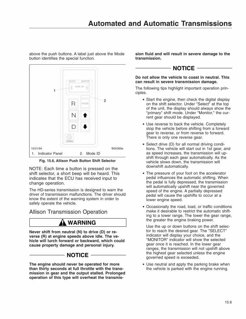
above the push buttons. A label just above the Modebutton identifies the special function.
NOTE: Each time a button is pressed on theshift selector, a short beep will be heard. Thisindicates that the ECU has received input tochange operation.
The HD-series transmission is designed to warn thedriver of transmission malfunctions. The driver shouldknow the extent of the warning system in order tosafely operate the vehicle.
Allison Transmission Operation
WARNINGNever shift from neutral (N) to drive (D) or re-verse (R) at engine speeds above idle. The ve-hicle will lurch forward or backward, which couldcause property damage and personal injury.
NOTICEThe engine should never be operated for morethan thirty seconds at full throttle with the trans-mission in gear and the output stalled. Prolongedoperation of this type will overheat the transmis-
sion fluid and will result in severe damage to thetransmission.
NOTICEDo not allow the vehicle to coast in neutral. Thiscan result in severe transmission damage.
The following tips highlight important operation prin-ciples.
• Start the engine, then check the digital displayon the shift selector. Under "Select" at the topof the unit, the display should always show the"primary" shift mode. Under "Monitor," the cur-rent gear should be displayed.
• Use reverse to back the vehicle. Completelystop the vehicle before shifting from a forwardgear to reverse, or from reverse to forward.There is only one reverse gear.
• Select drive (D) for all normal driving condi-tions. The vehicle will start out in 1st gear, andas speed increases, the transmission will up-shift through each gear automatically. As thevehicle slows down, the transmission willdownshift automatically.
• The pressure of your foot on the acceleratorpedal influences the automatic shifting. Whenthe pedal is fully depressed, the transmissionwill automatically upshift near the governedspeed of the engine. A partially depressedpedal will cause the upshifts to occur at alower engine speed.
• Occasionally the road, load, or traffic conditionsmake it desirable to restrict the automatic shift-ing to a lower range. The lower the gear range,the greater the engine braking power.
Use the up or down buttons on the shift selec-tor to reach the desired gear. The "SELECT"indicator will display your choice, and the"MONITOR" indicator will show the selectedgear once it is reached. In the lower gearranges, the transmission will not upshift abovethe highest gear selected unless the enginegoverned speed is exceeded.
• Use neutral and apply the parking brake whenthe vehicle is parked with the engine running.
10/31/94 f600369a
1
2
1. Indicator Panel 2. Mode ID
Fig. 15.6, Allison Push Button Shift Selector
Automated and Automatic Transmissions
15.6
16
Drive AxlesDrive Axles with Differential Lock . . . . . . . . . . . . . . . . . . . . . . . . . . . . . . . . . . . . . . . . . . . . . . . . . . . 16.1Interaxle Lock . . . . . . . . . . . . . . . . . . . . . . . . . . . . . . . . . . . . . . . . . . . . . . . . . . . . . . . . . . . . . . . . . . . 16.2Transfer Cases . . . . . . . . . . . . . . . . . . . . . . . . . . . . . . . . . . . . . . . . . . . . . . . . . . . . . . . . . . . . . . . . . . 16.3

Drive Axles with DifferentialLockThe driver-controlled differential lock feature (side-to-side wheel lock, traction control, or traction equalizer)provides maximum traction for slippery conditions byforcing the wheels on each drive axle governed bythe switch to rotate together. When the differentiallock is engaged, the clutch collar completely locksthe differential case, gearing, and axle shafts to-gether, maximizing the traction of both wheels.
Differential Lock SwitchThere are several differential lock options available:
• a switch to control the differential lock on theforward drive axle (see Fig. 16.1).
• a switch to control the differential lock on themiddle drive axle.
• a switch to control the differential lock on therear drive axle (see Fig. 16.2).
Differential Lock OperationNOTE: On some vehicles, the differential locksystem is connected through the low speedrange of the transmission. If this system is used,the transmission must be in the low speedrange for the wheels to fully lock. In addition,shifting out of low speed range will also disen-gage the differential lock.
WARNINGLocking the wheels when the vehicle is travelingdown steep grades or when the wheels are slip-ping could damage the differential and/or lead toloss of vehicle control, causing personal injuryand property damage.
NOTICEEngage the differential lock only when the ve-hicle is stopped or moving at less than 5 mph (8km/h). Engaging the differential lock at highspeeds can cause internal axle damage.
1. With the engine running, press the upper half ofthe differential lock switch to engage the differen-tial lock.
2. If the vehicle is moving, briefly let up on the ac-celerator to relieve torque on the gearing, allow-ing the differential to fully lock.
WARNINGBe especially careful when driving under slipperyconditions with the differential locked. Thoughforward traction is improved, the vehicle can stillslip sideways, causing possible loss of vehiclecontrol, personal injury, and property damage.
3. Drive cautiously and do not exceed 25 mph (40km/h). When the differential is fully locked, the
07/22/2011 f545803
Fig. 16.1, Forward Drive Axle Differential Lock Switch
07/22/2011 f545804
Fig. 16.2, Rear Drive Axle Differential Lock Switch
Drive Axles
16.1
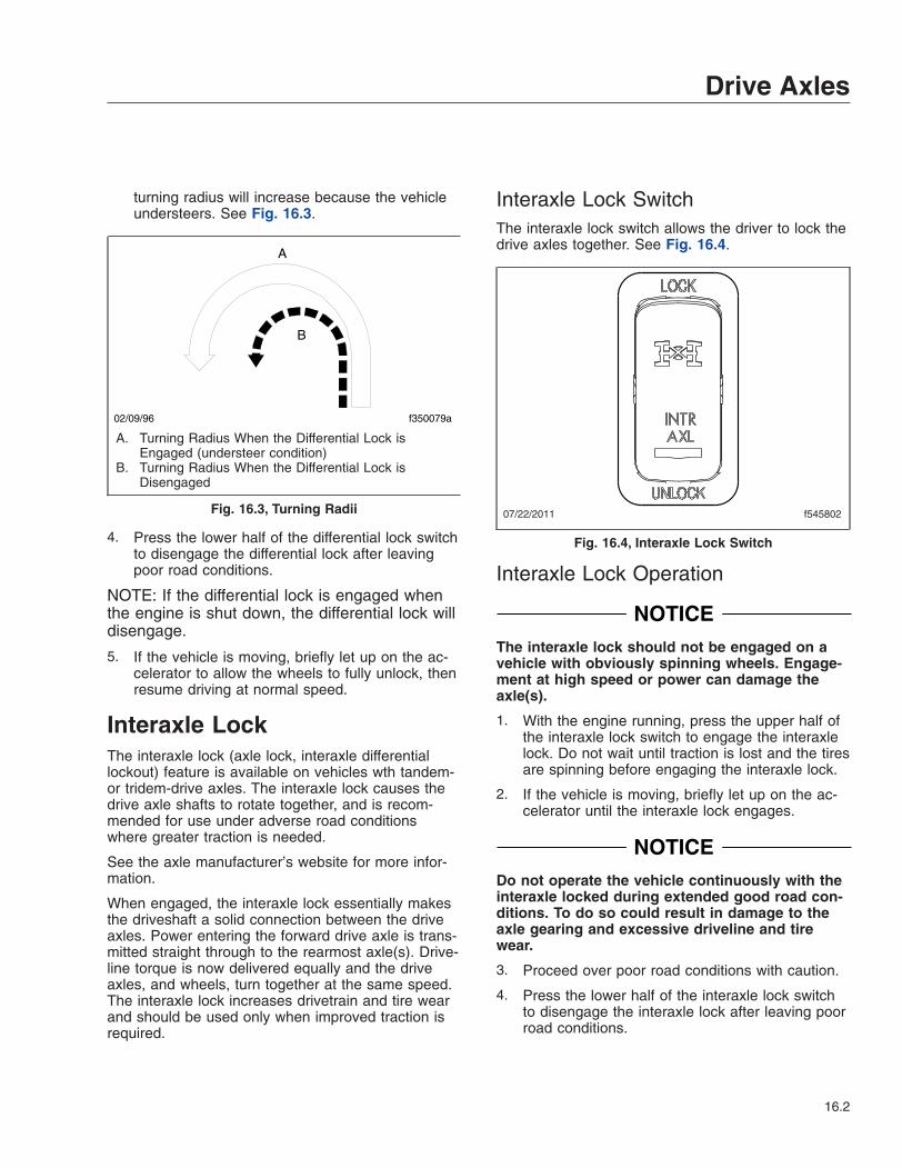
turning radius will increase because the vehicleundersteers. See Fig. 16.3.
4. Press the lower half of the differential lock switchto disengage the differential lock after leavingpoor road conditions.
NOTE: If the differential lock is engaged whenthe engine is shut down, the differential lock willdisengage.
5. If the vehicle is moving, briefly let up on the ac-celerator to allow the wheels to fully unlock, thenresume driving at normal speed.
Interaxle LockThe interaxle lock (axle lock, interaxle differentiallockout) feature is available on vehicles wth tandem-or tridem-drive axles. The interaxle lock causes thedrive axle shafts to rotate together, and is recom-mended for use under adverse road conditionswhere greater traction is needed.
See the axle manufacturer’s website for more infor-mation.
When engaged, the interaxle lock essentially makesthe driveshaft a solid connection between the driveaxles. Power entering the forward drive axle is trans-mitted straight through to the rearmost axle(s). Drive-line torque is now delivered equally and the driveaxles, and wheels, turn together at the same speed.The interaxle lock increases drivetrain and tire wearand should be used only when improved traction isrequired.
Interaxle Lock SwitchThe interaxle lock switch allows the driver to lock thedrive axles together. See Fig. 16.4.
Interaxle Lock Operation
NOTICEThe interaxle lock should not be engaged on avehicle with obviously spinning wheels. Engage-ment at high speed or power can damage theaxle(s).
1. With the engine running, press the upper half ofthe interaxle lock switch to engage the interaxlelock. Do not wait until traction is lost and the tiresare spinning before engaging the interaxle lock.
2. If the vehicle is moving, briefly let up on the ac-celerator until the interaxle lock engages.
NOTICEDo not operate the vehicle continuously with theinteraxle locked during extended good road con-ditions. To do so could result in damage to theaxle gearing and excessive driveline and tirewear.
3. Proceed over poor road conditions with caution.
4. Press the lower half of the interaxle lock switchto disengage the interaxle lock after leaving poorroad conditions.
02/09/96 f350079a
A
B
A. Turning Radius When the Differential Lock isEngaged (understeer condition)
B. Turning Radius When the Differential Lock isDisengaged
Fig. 16.3, Turning Radii 07/22/2011 f545802
Fig. 16.4, Interaxle Lock Switch
Drive Axles
16.2
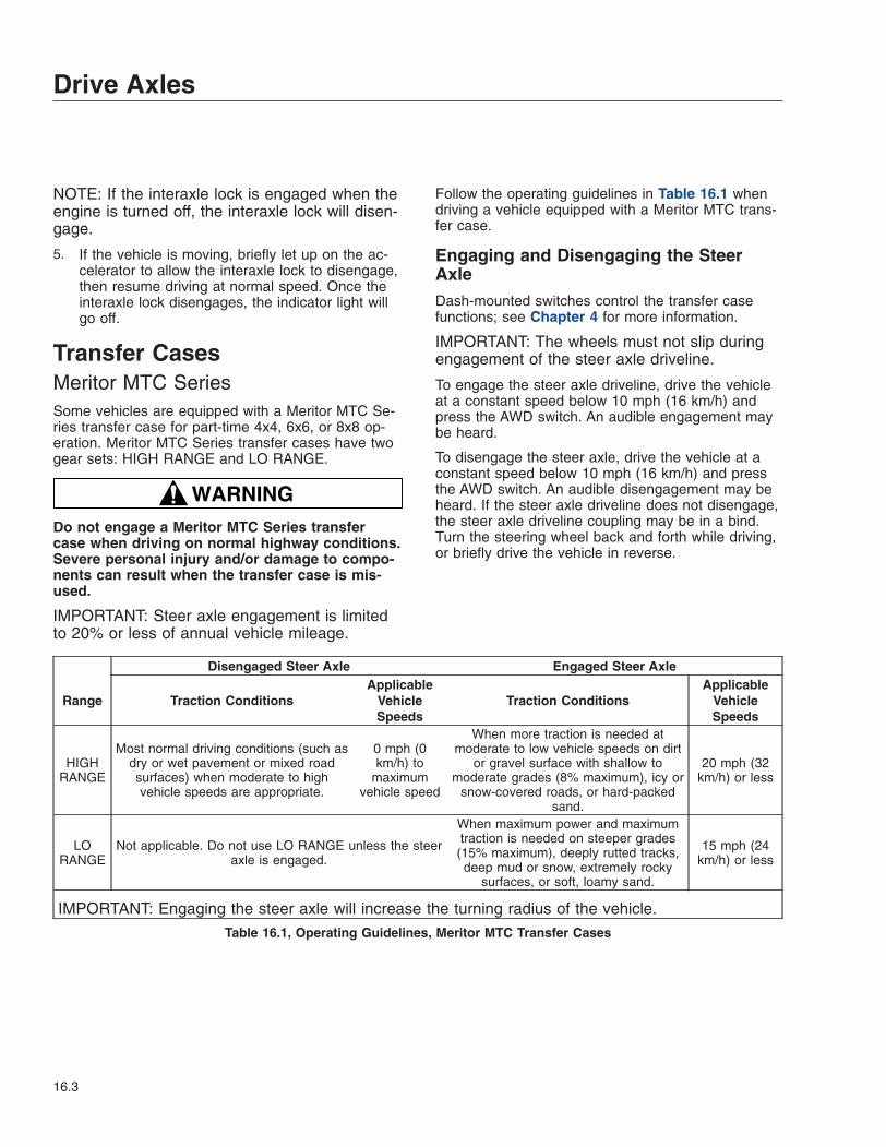
NOTE: If the interaxle lock is engaged when theengine is turned off, the interaxle lock will disen-gage.
5. If the vehicle is moving, briefly let up on the ac-celerator to allow the interaxle lock to disengage,then resume driving at normal speed. Once theinteraxle lock disengages, the indicator light willgo off.
Transfer CasesMeritor MTC SeriesSome vehicles are equipped with a Meritor MTC Se-ries transfer case for part-time 4x4, 6x6, or 8x8 op-eration. Meritor MTC Series transfer cases have twogear sets: HIGH RANGE and LO RANGE.
WARNINGDo not engage a Meritor MTC Series transfercase when driving on normal highway conditions.Severe personal injury and/or damage to compo-nents can result when the transfer case is mis-used.
IMPORTANT: Steer axle engagement is limitedto 20% or less of annual vehicle mileage.
Follow the operating guidelines in Table 16.1 whendriving a vehicle equipped with a Meritor MTC trans-fer case.
Engaging and Disengaging the SteerAxleDash-mounted switches control the transfer casefunctions; see Chapter 4 for more information.
IMPORTANT: The wheels must not slip duringengagement of the steer axle driveline.
To engage the steer axle driveline, drive the vehicleat a constant speed below 10 mph (16 km/h) andpress the AWD switch. An audible engagement maybe heard.
To disengage the steer axle, drive the vehicle at aconstant speed below 10 mph (16 km/h) and pressthe AWD switch. An audible disengagement may beheard. If the steer axle driveline does not disengage,the steer axle driveline coupling may be in a bind.Turn the steering wheel back and forth while driving,or briefly drive the vehicle in reverse.
Disengaged Steer Axle Engaged Steer Axle
Range Traction ConditionsApplicable
VehicleSpeeds
Traction ConditionsApplicable
VehicleSpeeds
HIGHRANGE
Most normal driving conditions (such asdry or wet pavement or mixed roadsurfaces) when moderate to highvehicle speeds are appropriate.
0 mph (0km/h) to
maximumvehicle speed
When more traction is needed atmoderate to low vehicle speeds on dirt
or gravel surface with shallow tomoderate grades (8% maximum), icy or
snow-covered roads, or hard-packedsand.
20 mph (32km/h) or less
LORANGE
Not applicable. Do not use LO RANGE unless the steeraxle is engaged.
When maximum power and maximumtraction is needed on steeper grades(15% maximum), deeply rutted tracks,deep mud or snow, extremely rocky
surfaces, or soft, loamy sand.
15 mph (24km/h) or less
IMPORTANT: Engaging the steer axle will increase the turning radius of the vehicle.
Table 16.1, Operating Guidelines, Meritor MTC Transfer Cases
Drive Axles
16.3
Shifting Between HIGH RANGE and LORANGEMTC Series transfer cases use an air cylinder to shiftbetween HIGH RANGE and LO RANGE. A dash-mounted switch operates the shift mechanism (seeChapter 4 for more information).
Shift between HIGH RANGE and LO RANGE, asfollows:
1. Stop the vehicle.
2. Shift the transmission to NEUTRAL.
3. Apply the parking brake.
4. Move the dash-mounted switch to the HIGH orLO RANGE position to pressurize the shiftmechanism in the transfer case. An audible en-gagement may be heard (which is normal).
5. Shift the transmission to FIRST gear and applylight torque to test the engagement.
If the shifter does not engage when shifting fromHIGH RANGE to LO RANGE, shift the transmis-sion into REVERSE, then NEUTRAL, and applylight torque to engage the LO RANGE.
Engaging PTOSome vehicles are equipped with a PTO mounted toa Meritor MTC transfer case. For these vehicles, en-gage the PTO only when the transfer case is in neu-tral, the transmission is in neutral/park, and the park-ing brake is applied. To begin using the PTO, selectthe drive gear based on the PTO system operatorsmanual.
Drive Axles
16.4

17
Fifth WheelsFifth Wheels, General Information . . . . . . . . . . . . . . . . . . . . . . . . . . . . . . . . . . . . . . . . . . . . . . . . . . . 17.1Fifth Wheel Coupling . . . . . . . . . . . . . . . . . . . . . . . . . . . . . . . . . . . . . . . . . . . . . . . . . . . . . . . . . . . . . 17.1Fifth Wheel Uncoupling . . . . . . . . . . . . . . . . . . . . . . . . . . . . . . . . . . . . . . . . . . . . . . . . . . . . . . . . . . . 17.5Fifth Wheel Slide . . . . . . . . . . . . . . . . . . . . . . . . . . . . . . . . . . . . . . . . . . . . . . . . . . . . . . . . . . . . . . . . 17.7
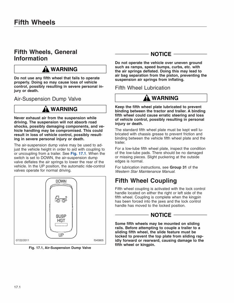
Fifth Wheels, GeneralInformation
WARNINGDo not use any fifth wheel that fails to operateproperly. Doing so may cause loss of vehiclecontrol, possibly resulting in severe personal in-jury or death.
Air-Suspension Dump Valve
WARNINGNever exhaust air from the suspension whiledriving. The suspension will not absorb roadshocks, possibly damaging components, and ve-hicle handling may be compromised. This couldresult in loss of vehicle control, possibly result-ing in severe personal injury or death.
The air-suspension dump valve may be used to ad-just the vehicle height in order to aid with coupling toor uncoupling from a trailer. See Fig. 17.1. When theswitch is set to DOWN, the air-suspension dumpvalve deflates the air springs to lower the rear of thevehicle. In the UP position, the automatic ride-controlvalves operate for normal driving.
NOTICEDo not operate the vehicle over uneven groundsuch as ramps, speed bumps, curbs, etc. withthe air springs deflated. Doing this may lead toair bag separation from the piston, preventing thesuspension air springs from inflating.
Fifth Wheel Lubrication
WARNINGKeep the fifth wheel plate lubricated to preventbinding between the tractor and trailer. A bindingfifth wheel could cause erratic steering and lossof vehicle control, possibly resulting in personalinjury or death.
The standard fifth wheel plate must be kept well lu-bricated with chassis grease to prevent friction andbinding between the vehicle fifth wheel plate and thetrailer.
For a low-lube fifth wheel plate, inspect the conditionof the low-lube pads. There should be no damagedor missing pieces. Slight puckering at the outsideedges is normal.
For lubrication instructions, see Group 31 of theWestern Star Maintenance Manual.
Fifth Wheel CouplingFifth wheel coupling is activated with the lock controlhandle located on either the right or left side of thefifth wheel. Coupling is complete when the kingpinhas been forced into the jaws and the lock controlhandle has moved to the locked position.
NOTICESome fifth wheels may be mounted on slidingrails. Before attempting to couple a trailer to asliding fifth wheel, the slide feature must belocked to prevent the top plate from sliding rap-idly forward or rearward, causing damage to thefifth wheel or kingpin.
07/22/2011 f545805
Fig. 17.1, Air-Suspension Dump Valve
Fifth Wheels
17.1

Coupling, Fontaine and Holland FifthWheelsNOTE: For a tractor equipped with a Jost fifthwheel, see the heading Coupling, Jost FifthWheel below.
1. Chock the front and rear trailer tires.
2. Ensure the fifth wheel jaw is fully open and theoperating rod is in the unlocked position. SeeFig. 17.2 or Fig. 17.3.
3. Make sure the fifth wheel top plate is tilted so theramps are as low as possible.
4. Position the tractor so that the center of the fifthwheel is in line with the trailer kingpin. The king-pin should be in a position to enter the throat ofthe locking mechanism. NOTICE
Attempting to couple at the wrong height maycause improper coupling, which could result indamage to the fifth wheel or kingpin.
5. Adjust the trailer height if required.
1
1
2
2 10/26/2010 f310110a
A
B
NOTE: Make sure the safety latch is down when thecontrol handle is locked.
A. Unlocked B. Locked1. Safety Latch 2. Lock Control Handle
Fig. 17.2, Fontaine Locking Mechanism
1
1
2
3
11/02/2010 f310447
1. Safety Latch2. Operating Rod
(locked)
3. Operating Rod(unlocked)
Fig. 17.3, Holland Simplex SE Locking Mechanism
10/28/2010 f311124
A
B
C
D
A. Fifth wheel must lifttrailer
B. Adjust trailer height
C. Ramps tilted downD. 4 to 8 inches
Fig. 17.4, Trailer Connection Point, Standard FifthWheel Plate
Fifth Wheels
17.2

For a standard fifth wheel plate, the trailershould contact the fifth wheel approximately 4 to8 inches (10 to 20 cm) behind the fifth wheelpivot. See Fig. 17.4.
For a low-lube fifth wheel plate, the fifth wheelmust slide freely under the trailer, and the trailershould contact the fifth wheel at the pivot. SeeFig. 17.5.
6. With the fifth wheel lock opening aligned with thetrailer kingpin, back the tractor slowly toward thetrailer. After sliding under the trailer, stop to avoidhitting the kingpin too hard, then resume backingslowly until the fifth wheel locks.
For a standard fifth wheel plate, the fifth wheelmust lift the trailer.
For a low-lube fifth wheel plate, do not lift thetrailer as this may damage the fifth wheel plate.
7. Set the tractor parking brake.
WARNINGA visual inspection is required by law. Some im-proper couplings can pass a pull test. Sound isnot reliable. Get out of the cab and look. Incor-rect coupling could cause the trailer to discon-nect, possibly resulting in serious personal injuryor death.
8. Perform a coupling inspection, checking thatthere is no gap between the bottom of the trailerand the fifth wheel, and that the kingpin is se-curely locked. See Fig. 17.6.
When lockup has occurred, the fifth wheel con-trol handle moves to the locked position. Makesure that the safety latch is down over the lockcontrol handle to hold the control handle in thelocked position (the safety latch will only rotatedown if the operating rod is fully retracted in thelocked position). See Fig. 17.2 or Fig. 17.3.
9. Release the tractor parking brake. Test for king-pin lockup by slowly inching the tractor forward,pulling on the trailer against the chocks.
10. After lockup is completed, connect the tractor-to-trailer air system lines and the electrical cable tothe trailer. Take care to prevent dirt or foreignmaterial from entering the air system lines.
NOTICEAlways make sure the connection hanger keepsthe trailer air hoses and electrical cables posi-tioned so that they do not rub on anything. Rub-bing may wear through hoses or cables, resultingin air leaks, or exposed or broken wires, poten-tially affecting trailer brake or electrical systems.
11. Charge the air brake system and check that theair connections do not leak.
WARNINGIncorrect fifth wheel lock adjustment could causethe trailer to disconnect, possibly resulting in se-rious personal injury or death.
12. With the trailer tires chocked and the brakes set,check for clearance between the kingpin and thefifth wheel jaws by moving the tractor forwardand backward against the locked kingpin. If slackis present, uncouple the trailer and have the fifth
09/10/2010 f311125
A
B
A. Adjust trailer height B. Ramps tilted down
Fig. 17.5, Trailer Connection Point, Low-Lube FifthWheel Plate
09/10/2010 f311126
A B
A. No gap between trailerand fifth wheel
B. Kingpin inside lock
Fig. 17.6, Coupling Inspection
Fifth Wheels
17.3
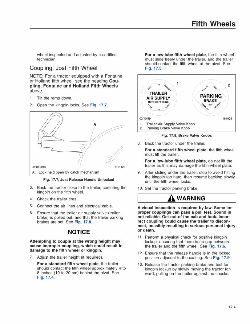
wheel inspected and adjusted by a certifiedtechnician.
Coupling, Jost Fifth WheelNOTE: For a tractor equipped with a Fontaineor Holland fifth wheel, see the heading Cou-pling, Fontaine and Holland Fifth Wheelsabove.
1. Tilt the ramp down.
2. Open the kingpin locks. See Fig. 17.7.
3. Back the tractor close to the trailer, centering thekingpin on the fifth wheel.
4. Chock the trailer tires.
5. Connect the air lines and electrical cable.
6. Ensure that the trailer air supply valve (trailerbrake) is pulled out, and that the trailer parkingbrakes are set. See Fig. 17.8.
NOTICEAttempting to couple at the wrong height maycause improper coupling, which could result indamage to the fifth wheel or kingpin.
7. Adjust the trailer height (if required).
For a standard fifth wheel plate, the trailershould contact the fifth wheel approximately 4 to8 inches (10 to 20 cm) behind the pivot. SeeFig. 17.4.
For a low-lube fifth wheel plate, the fifth wheelmust slide freely under the trailer, and the trailershould contact the fifth wheel at the pivot. SeeFig. 17.5.
8. Back the tractor under the trailer.
For a standard fifth wheel plate, the fifth wheelmust lift the trailer.
For a low-lube fifth wheel plate, do not lift thetrailer as this may damage the fifth wheel plate.
9. After sliding under the trailer, stop to avoid hittingthe kingpin too hard, then resume backing slowlyuntil the fifth wheel locks.
10. Set the tractor parking brake.
WARNINGA visual inspection is required by law. Some im-proper couplings can pass a pull test. Sound isnot reliable. Get out of the cab and look. Incor-rect coupling could cause the trailer to discon-nect, possibly resulting in serious personal injuryor death.
11. Perform a physical check for positive kingpinlockup, ensuring that there is no gap betweenthe trailer and the fifth wheel. See Fig. 17.6.
12. Ensure that the release handle is in the lockedposition adjacent to the casting. See Fig. 17.9.
13. Release the tractor parking brake and test forkingpin lockup by slowly moving the tractor for-ward, pulling on the trailer against the chocks.
09/10/2010 f311128
A
A. Lock held open by catch mechanism
Fig. 17.7, Jost Release Handle Unlocked
f610291
1 2
03/10/99
1. Trailer Air Supply Valve Knob2. Parking Brake Valve Knob
Fig. 17.8, Brake Valve Knobs
Fifth Wheels
17.4
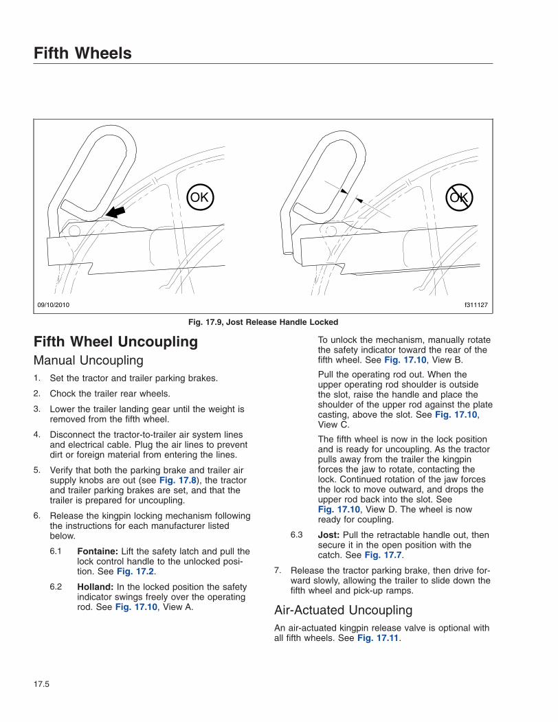
Fifth Wheel UncouplingManual Uncoupling1. Set the tractor and trailer parking brakes.
2. Chock the trailer rear wheels.
3. Lower the trailer landing gear until the weight isremoved from the fifth wheel.
4. Disconnect the tractor-to-trailer air system linesand electrical cable. Plug the air lines to preventdirt or foreign material from entering the lines.
5. Verify that both the parking brake and trailer airsupply knobs are out (see Fig. 17.8), the tractorand trailer parking brakes are set, and that thetrailer is prepared for uncoupling.
6. Release the kingpin locking mechanism followingthe instructions for each manufacturer listedbelow.
6.1 Fontaine: Lift the safety latch and pull thelock control handle to the unlocked posi-tion. See Fig. 17.2.
6.2 Holland: In the locked position the safetyindicator swings freely over the operatingrod. See Fig. 17.10, View A.
To unlock the mechanism, manually rotatethe safety indicator toward the rear of thefifth wheel. See Fig. 17.10, View B.
Pull the operating rod out. When theupper operating rod shoulder is outsidethe slot, raise the handle and place theshoulder of the upper rod against the platecasting, above the slot. See Fig. 17.10,View C.
The fifth wheel is now in the lock positionand is ready for uncoupling. As the tractorpulls away from the trailer the kingpinforces the jaw to rotate, contacting thelock. Continued rotation of the jaw forcesthe lock to move outward, and drops theupper rod back into the slot. SeeFig. 17.10, View D. The wheel is nowready for coupling.
6.3 Jost: Pull the retractable handle out, thensecure it in the open position with thecatch. See Fig. 17.7.
7. Release the tractor parking brake, then drive for-ward slowly, allowing the trailer to slide down thefifth wheel and pick-up ramps.
Air-Actuated UncouplingAn air-actuated kingpin release valve is optional withall fifth wheels. See Fig. 17.11.
09/10/2010 f311127
OK OK
Fig. 17.9, Jost Release Handle Locked
Fifth Wheels
17.5

NOTE: In the event of an air system failure, air-actuated kingpins can be manually released fol-lowing the instructions for manual unlocking.
WARNINGOnce the kingpin release valve has been pulledthe kingpin lock is released. The vehicle MUSTNOT be driven with the trailer until the trailer hasbeen uncoupled and coupled again. Failure to doso may result in separation of the trailer from the
11/02/2010 f311133
A
B
C
D
1
2
3
4
A. Locked PositionB. Unlatched Position (safety indicator rotated towards the rear of the fifth wheel)C. Lock Position (upper rod resting against casting above slot)D. Open Position (ready for coupling)1. Safety Indicator2. Operating Rod
3. Upper Rod4. Plate Casting
Fig. 17.10, Holland Kingpin Locking Mechanism
Fifth Wheels
17.6
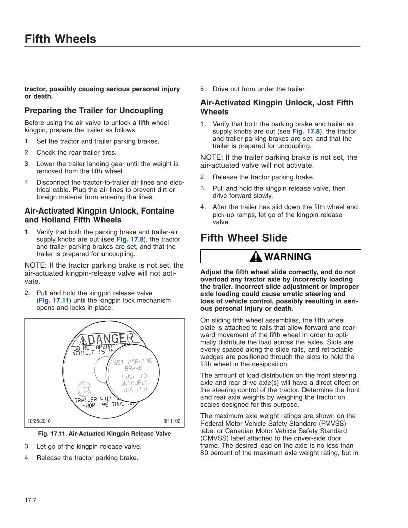
tractor, possibly causing serious personal injuryor death.
Preparing the Trailer for UncouplingBefore using the air valve to unlock a fifth wheelkingpin, prepare the trailer as follows.
1. Set the tractor and trailer parking brakes.
2. Chock the rear trailer tires.
3. Lower the trailer landing gear until the weight isremoved from the fifth wheel.
4. Disconnect the tractor-to-trailer air lines and elec-trical cable. Plug the air lines to prevent dirt orforeign material from entering the lines.
Air-Activated Kingpin Unlock, Fontaineand Holland Fifth Wheels1. Verify that both the parking brake and trailer-air
supply knobs are out (see Fig. 17.8), the tractorand trailer parking brakes are set, and that thetrailer is prepared for uncoupling.
NOTE: If the tractor parking brake is not set, theair-actuated kingpin-release valve will not acti-vate.
2. Pull and hold the kingpin release valve(Fig. 17.11) until the kingpin lock mechanismopens and locks in place.
3. Let go of the kingpin release valve.
4. Release the tractor parking brake.
5. Drive out from under the trailer.
Air-Activated Kingpin Unlock, Jost FifthWheels1. Verify that both the parking brake and trailer air
supply knobs are out (see Fig. 17.8), the tractorand trailer parking brakes are set, and that thetrailer is prepared for uncoupling.
NOTE: If the trailer parking brake is not set, theair-actuated valve will not activate.
2. Release the tractor parking brake.
3. Pull and hold the kingpin release valve, thendrive forward slowly.
4. After the trailer has slid down the fifth wheel andpick-up ramps, let go of the kingpin releasevalve.
Fifth Wheel Slide
WARNINGAdjust the fifth wheel slide correctly, and do notoverload any tractor axle by incorrectly loadingthe trailer. Incorrect slide adjustment or improperaxle loading could cause erratic steering andloss of vehicle control, possibly resulting in seri-ous personal injury or death.
On sliding fifth wheel assemblies, the fifth wheelplate is attached to rails that allow forward and rear-ward movement of the fifth wheel in order to opti-mally distribute the load across the axles. Slots areevenly spaced along the slide rails, and retractablewedges are positioned through the slots to hold thefifth wheel in the desiposition.
The amount of load distribution on the front steeringaxle and rear drive axle(s) will have a direct effect onthe steering control of the tractor. Determine the frontand rear axle weights by weighing the tractor onscales designed for this purpose.
The maximum axle weight ratings are shown on theFederal Motor Vehicle Safety Standard (FMVSS)label or Canadian Motor Vehicle Safety Standard(CMVSS) label attached to the driver-side doorframe. The desired load on the axle is no less than80 percent of the maximum axle weight rating, but in
10/26/2010 f611102
Fig. 17.11, Air-Actuated Kingpin Release Valve
Fifth Wheels
17.7
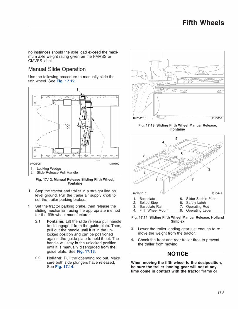
no instances should the axle load exceed the maxi-mum axle weight rating given on the FMVSS orCMVSS label.
Manual Slide OperationUse the following procedure to manually slide thefifth wheel. See Fig. 17.12.
1. Stop the tractor and trailer in a straight line onlevel ground. Pull the trailer air supply knob toset the trailer parking brakes.
2. Set the tractor parking brake, then release thesliding mechanism using the appropriate methodfor the fifth wheel manufacturer.
2.1 Fontaine: Lift the slide release pull handleto disengage it from the guide plate. Then,pull out the handle until it is in the un-locked position and can be positionedagainst the guide plate to hold it out. Thehandle will stay in the unlocked positionuntil it is manually disengaged from theguide plate. See Fig. 17.13.
2.2 Holland: Pull the operating rod out. Makesure both side plungers have released.See Fig. 17.14.
3. Lower the trailer landing gear just enough to re-move the weight from the tractor.
4. Chock the front and rear trailer tires to preventthe trailer from moving.
NOTICEWhen moving the fifth wheel to the desiposition,be sure the trailer landing gear will not at anytime come in contact with the tractor frame or
07/25/95 f310190
1
2
1. Locking Wedge2. Slide Release Pull Handle
Fig. 17.12, Manual Release Sliding Fifth Wheel,Fontaine
10/26/2010 f310050
Fig. 17.13, Sliding Fifth Wheel Manual Release,Fontaine
1
2
3
45
6
3
10/26/2010 f310445
7
8
1. Baseplate2. Bolted Stop3. Baseplate Rail4. Fifth Wheel Mount
5. Slider Saddle Plate6. Safety Latch7. Operating Rod8. Operating Lever
Fig. 17.14, Sliding Fifth Wheel Manual Release, HollandSimplex
Fifth Wheels
17.8
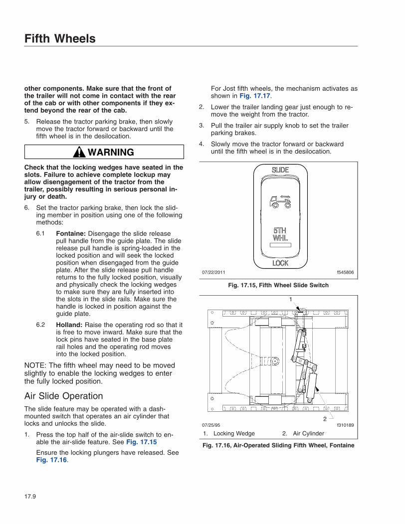
other components. Make sure that the front ofthe trailer will not come in contact with the rearof the cab or with other components if they ex-tend beyond the rear of the cab.
5. Release the tractor parking brake, then slowlymove the tractor forward or backward until thefifth wheel is in the desilocation.
WARNINGCheck that the locking wedges have seated in theslots. Failure to achieve complete lockup mayallow disengagement of the tractor from thetrailer, possibly resulting in serious personal in-jury or death.
6. Set the tractor parking brake, then lock the slid-ing member in position using one of the followingmethods:
6.1 Fontaine: Disengage the slide releasepull handle from the guide plate. The sliderelease pull handle is spring-loaded in thelocked position and will seek the lockedposition when disengaged from the guideplate. After the slide release pull handlereturns to the fully locked position, visuallyand physically check the locking wedgesto make sure they are fully inserted intothe slots in the slide rails. Make sure thehandle is locked in position against theguide plate.
6.2 Holland: Raise the operating rod so that itis free to move inward. Make sure that thelock pins have seated in the base platerail holes and the operating rod movesinto the locked position.
NOTE: The fifth wheel may need to be movedslightly to enable the locking wedges to enterthe fully locked position.
Air Slide OperationThe slide feature may be operated with a dash-mounted switch that operates an air cylinder thatlocks and unlocks the slide.
1. Press the top half of the air-slide switch to en-able the air-slide feature. See Fig. 17.15
Ensure the locking plungers have released. SeeFig. 17.16.
For Jost fifth wheels, the mechanism activates asshown in Fig. 17.17.
2. Lower the trailer landing gear just enough to re-move the weight from the tractor.
3. Pull the trailer air supply knob to set the trailerparking brakes.
4. Slowly move the tractor forward or backwarduntil the fifth wheel is in the desilocation.
07/22/2011 f545806
Fig. 17.15, Fifth Wheel Slide Switch
07/25/95 f310189
1
2
1. Locking Wedge 2. Air Cylinder
Fig. 17.16, Air-Operated Sliding Fifth Wheel, Fontaine
Fifth Wheels
17.9
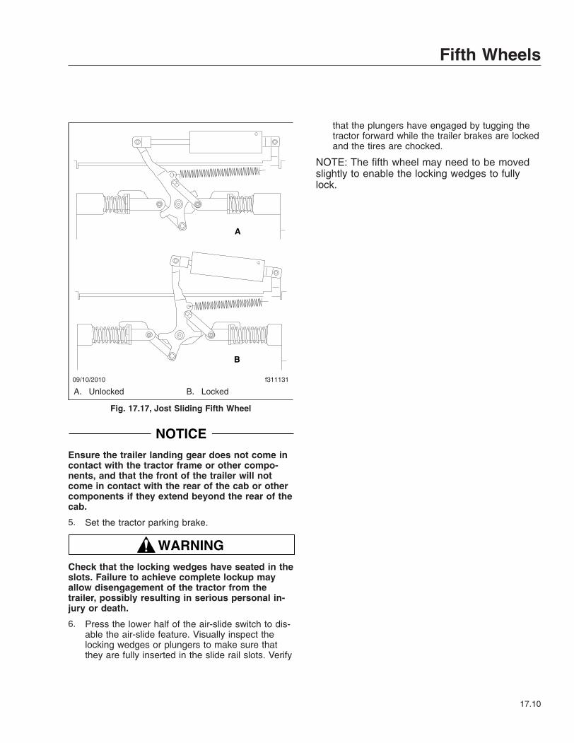
NOTICEEnsure the trailer landing gear does not come incontact with the tractor frame or other compo-nents, and that the front of the trailer will notcome in contact with the rear of the cab or othercomponents if they extend beyond the rear of thecab.
5. Set the tractor parking brake.
WARNINGCheck that the locking wedges have seated in theslots. Failure to achieve complete lockup mayallow disengagement of the tractor from thetrailer, possibly resulting in serious personal in-jury or death.
6. Press the lower half of the air-slide switch to dis-able the air-slide feature. Visually inspect thelocking wedges or plungers to make sure thatthey are fully inserted in the slide rail slots. Verify
that the plungers have engaged by tugging thetractor forward while the trailer brakes are lockedand the tires are chocked.
NOTE: The fifth wheel may need to be movedslightly to enable the locking wedges to fullylock.
09/10/2010 f311131
A
B
A. Unlocked B. Locked
Fig. 17.17, Jost Sliding Fifth Wheel
Fifth Wheels
17.10
18
Trailer CouplingsAir-Suspension Dump Valve . . . . . . . . . . . . . . . . . . . . . . . . . . . . . . . . . . . . . . . . . . . . . . . . . . . . . . . 18.1Premier Trailer Couplings . . . . . . . . . . . . . . . . . . . . . . . . . . . . . . . . . . . . . . . . . . . . . . . . . . . . . . . . . 18.1
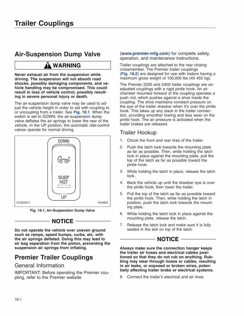
Air-Suspension Dump Valve
WARNINGNever exhaust air from the suspension whiledriving. The suspension will not absorb roadshocks, possibly damaging components, and ve-hicle handling may be compromised. This couldresult in loss of vehicle control, possibly result-ing in severe personal injury or death.
The air-suspension dump valve may be used to ad-just the vehicle height in order to aid with coupling toor uncoupling from a trailer. See Fig. 18.1. When theswitch is set to DOWN, the air-suspension dumpvalve deflates the air springs to lower the rear of thevehicle. In the UP position, the automatic ride-controlvalves operate for normal driving.
NOTICEDo not operate the vehicle over uneven groundsuch as ramps, speed bumps, curbs, etc. withthe air springs deflated. Doing this may lead toair bag separation from the piston, preventing thesuspension air springs from inflating.
Premier Trailer CouplingsGeneral InformationIMPORTANT: Before operating the Premier cou-pling, refer to the Premier website
(www.premier-mfg.com) for complete safety,operation, and maintenance instructions.
Trailer couplings are attached to the rear closingcrossmember. The Premier trailer couplings(Fig. 18.2) are designed for use with trailers having amaximum gross weight of 100,000 lbs (45 455 kg).
The Premier 2200 and 2400 trailer couplings are air-adjusted couplings with a rigid pintle hook. An airchamber mounted forward of the coupling operates apush rod, which pushes against a shoe inside thecoupling. The shoe maintains constant pressure onthe eye of the trailer drawbar when it’s over the pintlehook. This takes up any slack in the trailer connec-tion, providing smoother towing and less wear on thepintle hook. The air pressure is activated when thetrailer brakes are released.
Trailer Hookup1. Chock the front and rear tires of the trailer.
2. Push the latch lock towards the mounting plateas far as possible. Then, while holding the latchlock in place against the mounting plate, pull thetop of the latch as far as possible toward thepintle hook.
3. While holding the latch in place, release the latchlock.
4. Back the vehicle up until the drawbar eye is overthe pintle hook, then lower the trailer.
5. Pull the top of the latch as far as possible towardthe pintle hook. Then, while holding the latch inposition, push the latch lock towards the mount-ing plate.
6. While holding the latch lock in place against themounting plate, release the latch.
7. Release the latch lock and make sure it is fullyseated in the slot on top of the latch.
NOTICEAlways make sure the connection hanger keepsthe trailer air hoses and electrical cables posi-tioned so that they do not rub on anything. Rub-bing may wear through hoses or cables, resultingin air leaks, or exposed or broken wires, poten-tially affecting trailer brake or electrical systems.
8. Connect the trailer’s electrical and air lines.
07/22/2011 f545805
Fig. 18.1, Air-Suspension Dump Valve
Trailer Couplings
18.1

Trailer Release1. Set the vehicle and trailer parking brakes.
WARNINGIf a trailer or combination vehicle is not equippedwith spring parking brakes, do not park it by pull-ing out only the trailer air supply valve knob.This would apply only the trailer service brakes.If air were to bleed from the trailer brake system,the trailer brakes would release, possibly causingan unattended runaway vehicle.
2. Chock the front and rear tires of the trailer.
3. Disconnect the trailer air and electrical lines.Plug the air lines to keep them free of dirt.
4. Take the weight of the trailer drawbar eye off thepintle hook.
5. Push the latch lock towards the mounting plateas far as possible. Then, while holding the latchlock in this position, pull the top of the latch asfar as possible toward the pintle hook.
6. While holding the latch in place, release the latchlock.
7. Slowly drive the vehicle away from the trailer.
12/08/2010 f311138
1 1
2
2
3 3A B
A. Premiere 2400 Trailer Coupling B. Premiere 2200 Trailer Coupling1. Latch Lock2. Latch
3. Pintle Hook
Fig. 18.2, Premiere 2200 and 2400 Trailer Couplings
Trailer Couplings
18.2
19
Headlight AimingPreliminary Checks . . . . . . . . . . . . . . . . . . . . . . . . . . . . . . . . . . . . . . . . . . . . . . . . . . . . . . . . . . . . . . . 19.1Checking Headlight Aim . . . . . . . . . . . . . . . . . . . . . . . . . . . . . . . . . . . . . . . . . . . . . . . . . . . . . . . . . . . 19.1Adjusting Headlight Aim . . . . . . . . . . . . . . . . . . . . . . . . . . . . . . . . . . . . . . . . . . . . . . . . . . . . . . . . . . . 19.1
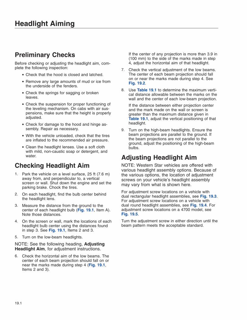
Preliminary ChecksBefore checking or adjusting the headlight aim, com-plete the following inspection:
• Check that the hood is closed and latched.
• Remove any large amounts of mud or ice fromthe underside of the fenders.
• Check the springs for sagging or brokenleaves.
• Check the suspension for proper functioning ofthe leveling mechanism. On cabs with air sus-pensions, make sure that the height is properlyadjusted.
• Check for damage to the hood and hinge as-sembly. Repair as necessary.
• With the vehicle unloaded, check that the tiresare inflated to the recommended air pressure.
• Clean the headlight lenses. Use a soft clothwith mild, non-caustic soap or detergent, andwater.
Checking Headlight Aim1. Park the vehicle on a level surface, 25 ft (7.6 m)
away from, and perpendicular to, a verticalscreen or wall. Shut down the engine and set theparking brake. Chock the tires.
2. On each headlight, find the bulb center behindthe headlight lens.
3. Measure the distance from the ground to thecenter of each headlight bulb (Fig. 19.1, Item A).Note those distances.
4. On the screen or wall, mark the locations of eachheadlight bulb center using the distances foundin step 3. See Fig. 19.1, Items 2 and 3.
5. Turn on the low-beam headlights.
NOTE: See the following heading, AdjustingHeadlight Aim, for adjustment instructions.
6. Check the horizontal aim of the low beams. Thecenter of each beam projection should fall on ornear the marks made during step 4 (Fig. 19.1,Items 2 and 3).
If the center of any projection is more than 3.9 in(100 mm) to the side of the marks made in step4, adjust the horizontal aim of that headlight.
7. Check the vertical adjustment of the low beams.The center of each beam projection should fallon or near the marks made during step 4. SeeFig. 19.2.
8. Use Table 19.1 to determine the maximum verti-cal distance allowable between the marks on thewall and the center of each low-beam projection.
If the distance between either projection centerand the mark made on the wall or screen isgreater than the maximum distance given inTable 19.1, adjust the vertical positioning of thatheadlight.
9. Turn on the high-beam headlights. Ensure thebeam projections are parallel to the ground. Ifthe beam projections are not parallel to theground, adjust the positioning of the high-beambulbs.
Adjusting Headlight AimNOTE: Western Star vehicles are offered withvarious headlight assembly options. Because ofthe various options, the location of adjustmentscrews on your vehicle’s headlight assemblymay vary from what is shown here.
For adjustment screw locations on a vehicle withdual rectangular headlight assemblies, see Fig. 19.3.For adjustment screw locations on a vehicle withdual round headlight assemblies, see Fig. 19.4. Foradjustment screw locations on a 4700 model, seeFig. 19.5.
Turn the adjustment screw in either direction until thebeam pattern meets the acceptable standard.
Headlight Aiming
19.1
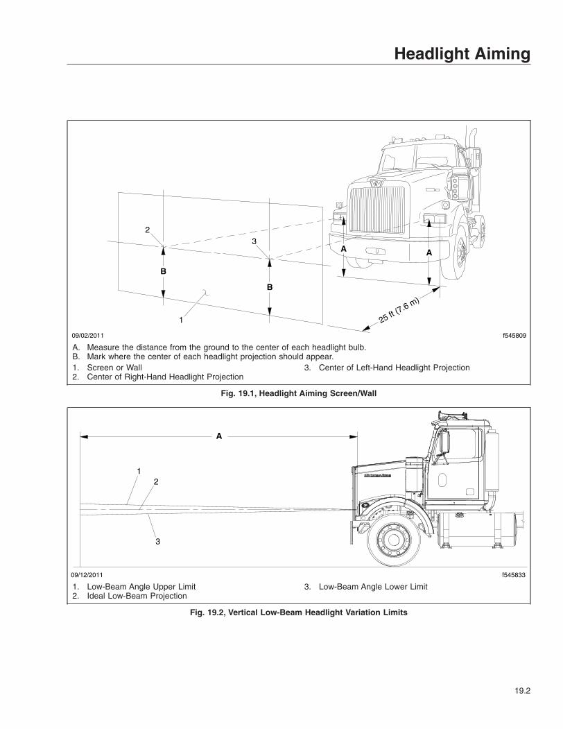
f545809
25 ft (7.6 m)
09/02/2011
AA
B
B
1
23
A. Measure the distance from the ground to the center of each headlight bulb.B. Mark where the center of each headlight projection should appear.1. Screen or Wall2. Center of Right-Hand Headlight Projection
3. Center of Left-Hand Headlight Projection
Fig. 19.1, Headlight Aiming Screen/Wall
09/12/2011 f545833
A
12
3
1. Low-Beam Angle Upper Limit2. Ideal Low-Beam Projection
3. Low-Beam Angle Lower Limit
Fig. 19.2, Vertical Low-Beam Headlight Variation Limits
Headlight Aiming
19.2

Vertical Low-Beam Headlight Variation LimitsDistance Between Ground
and Headlight: in (mm)Desired Variation (Fig. 19.2,
Item 2) : in (mm)Upper Limit (Fig. 19.2, Item
1): in (mm) upLower Limit (Fig. 19.2, Item
3): in (mm) down22–36 (560–900) 0 3.9 (100) 3.9 (100)
36–48 (900–1200) 2 (50) down 2 (50) 6 (150)48–54 (1200–1400) 2.5 (64) down 1.6 (40) 6.5 (165)
Table 19.1, Vertical Low-Beam Headlight Variation Limits
02/17/2005 f544577a
NOTE: The vertical adjustment screws are on top ofeach bulb; the horizontal adjustment screws are on theside of each bulb.
Fig. 19.3, Adjustment Screw Locations, DualRectangular Headlights
09/14/2011 f545834
1
2
3
1. Horizontal Adjustment Screw2. Vertical Adjustment Screw3. Bezel Mounting Screw
Fig. 19.4, Adjustment Screw Locations, Dual RoundHeadlights
Headlight Aiming
19.3
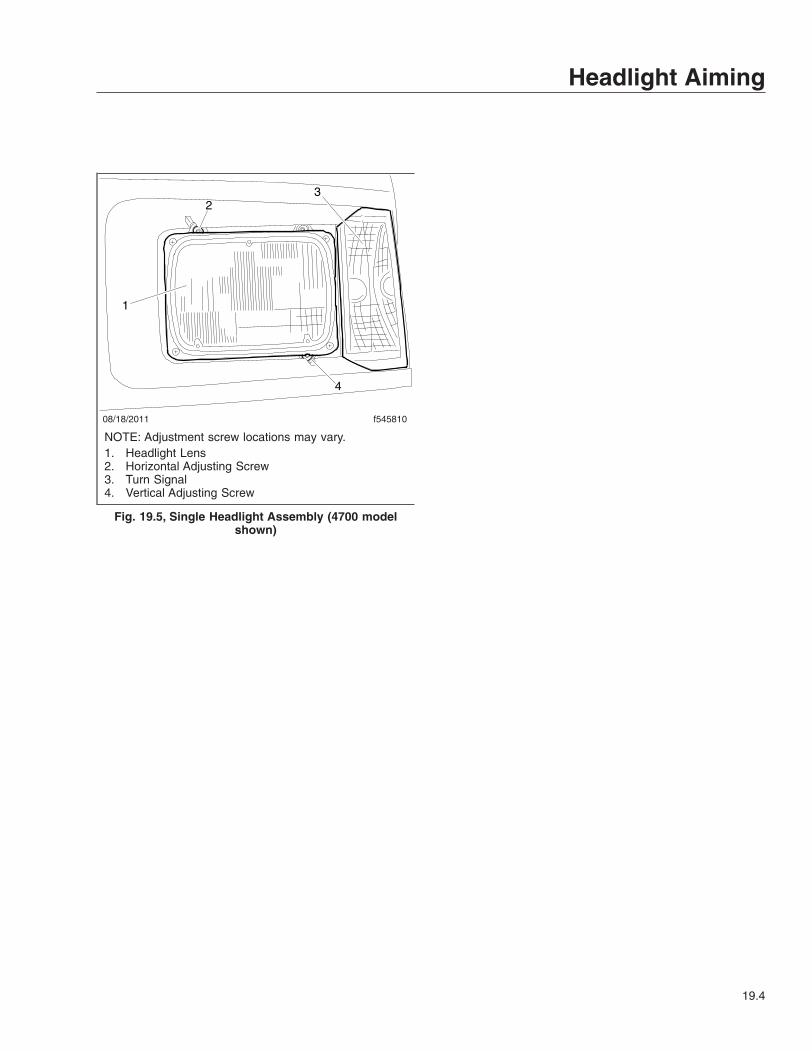
08/18/2011 f545810
1
23
4
NOTE: Adjustment screw locations may vary.1. Headlight Lens2. Horizontal Adjusting Screw3. Turn Signal4. Vertical Adjusting Screw
Fig. 19.5, Single Headlight Assembly (4700 modelshown)
Headlight Aiming
19.4

20
Vehicle Appearance andCare
Cab Washing and Polishing . . . . . . . . . . . . . . . . . . . . . . . . . . . . . . . . . . . . . . . . . . . . . . . . . . . . . . . . 20.1Care of Chrome Parts . . . . . . . . . . . . . . . . . . . . . . . . . . . . . . . . . . . . . . . . . . . . . . . . . . . . . . . . . . . . 20.1Dashboard Care . . . . . . . . . . . . . . . . . . . . . . . . . . . . . . . . . . . . . . . . . . . . . . . . . . . . . . . . . . . . . . . . . 20.1Vinyl Upholstery Cleaning . . . . . . . . . . . . . . . . . . . . . . . . . . . . . . . . . . . . . . . . . . . . . . . . . . . . . . . . . 20.2Velour Upholstery Cleaning . . . . . . . . . . . . . . . . . . . . . . . . . . . . . . . . . . . . . . . . . . . . . . . . . . . . . . . . 20.2Star Gauge Face Care . . . . . . . . . . . . . . . . . . . . . . . . . . . . . . . . . . . . . . . . . . . . . . . . . . . . . . . . . . . . 20.3Care of Exterior Lights . . . . . . . . . . . . . . . . . . . . . . . . . . . . . . . . . . . . . . . . . . . . . . . . . . . . . . . . . . . . 20.3

Cab Washing and PolishingIMPORTANT: Carefully read all instructions be-fore using or applying any cleaner or product tothe vehicle or components. Failure to followmanufacturers’ recommendations can result indamage to the finish.
To protect the finish of a new vehicle, follow theseguidelines carefully:
• During the first 30 days, rinse the vehicle fre-quently with water. If the vehicle is dirty, use amild liquid soap. Do not use detergent.
• During the first 30 days, do not use anythingabrasive on the vehicle. Brushes, chemicals,and cleaners may scratch the finish.
• During the first 120 days, do not wax thevehicle.
To extend the life of the vehicle’s finish, follow theseguidelines:
• Avoid washing the vehicle in the hot sun.
• Always wash the vehicle with water. After thecab is completely washed, dry it with a towel orchamois.
• Do not dust painted surfaces with a dry cloth,as this will scratch the paint.
• Do not remove ice or snow from a painted sur-face with a scraper of any sort.
• To prevent damage to the finish, wax it regu-larly. Before waxing, if the finish has becomedull, remove oxidized paint using a cleanerspecifically designed for this purpose. Removeall road tar and tree sap before waxing. West-ern Star Trucks recommends using a highquality brand of cleaner or cleaner-polish andpolishing wax.
• Do not let diesel fuel or antifreeze stand on apainted surface. If either should occur, rinsethe surface off with water.
• To prevent rust, have any nicks or other dam-age on the finish touched up as soon as pos-sible.
• Park the vehicle in a sheltered area wheneverpossible.
To prevent delamination and deterioration of labelsand stickers on the cab, follow these guidlines care-fully:
• Do not pressure wash the label or sticker orsurfaces near it.
• Do not use strong alkaline soaps on or nearthe label or sticker.
Care of Fiberglass PartsWash unpainted fiberglass air fairings and shieldsmonthly with a mild detergent, such as dishwashingliquid. Avoid strong alkaline cleansers.
Apply a wax specifically designed for fiberglass.
Care of Chrome PartsTo prevent rust, keep chrome parts clean and pro-tected at all times. This is especially important duringwinter driving and in coastal areas where there isexposure to salt air.
When cleaning chrome, use clean water and a softcloth or sponge. A mild detergent may also be used.
Sponge gently, then rinse. If necessary, use a non-abrasive chrome cleaner to remove stubborn rust orother material. Do not use steel wool.
To help protect chrome after cleaning, apply a coat ofpolishing wax to the surface. Never use wax on com-ponents that are exposed to high heat, such as ex-haust pipes.
Dashboard Care
NOTICEWhen cleaning the dashboard, instrument panel,or gauge lens covers, do not use Armor-All Pro-tectant®, STP Son-of-a-Gun®, window cleaner, orother equivalent treatments. These cleaners con-tain vinyl plasticizers which can cause stresscrazing in the interior plastic panels and can re-sult in cracking of the panels. Some cleaners canalso have an adverse effect on the clear plasticof instrument panels and gauge lens covers, re-sulting in a foggy or cloudy appearance. Thistype of damage is not covered by vehicle war-ranty.
Vehicle Appearance and Care
20.1
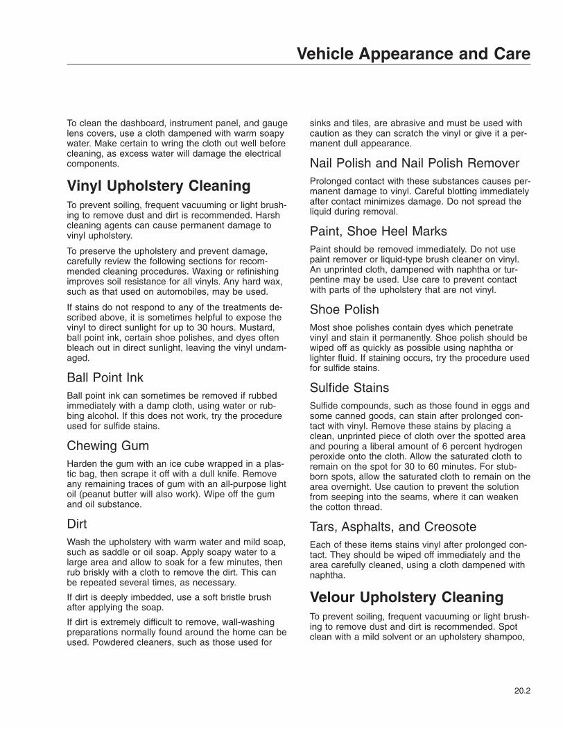
To clean the dashboard, instrument panel, and gaugelens covers, use a cloth dampened with warm soapywater. Make certain to wring the cloth out well beforecleaning, as excess water will damage the electricalcomponents.
Vinyl Upholstery CleaningTo prevent soiling, frequent vacuuming or light brush-ing to remove dust and dirt is recommended. Harshcleaning agents can cause permanent damage tovinyl upholstery.
To preserve the upholstery and prevent damage,carefully review the following sections for recom-mended cleaning procedures. Waxing or refinishingimproves soil resistance for all vinyls. Any hard wax,such as that used on automobiles, may be used.
If stains do not respond to any of the treatments de-scribed above, it is sometimes helpful to expose thevinyl to direct sunlight for up to 30 hours. Mustard,ball point ink, certain shoe polishes, and dyes oftenbleach out in direct sunlight, leaving the vinyl undam-aged.
Ball Point InkBall point ink can sometimes be removed if rubbedimmediately with a damp cloth, using water or rub-bing alcohol. If this does not work, try the procedureused for sulfide stains.
Chewing GumHarden the gum with an ice cube wrapped in a plas-tic bag, then scrape it off with a dull knife. Removeany remaining traces of gum with an all-purpose lightoil (peanut butter will also work). Wipe off the gumand oil substance.
DirtWash the upholstery with warm water and mild soap,such as saddle or oil soap. Apply soapy water to alarge area and allow to soak for a few minutes, thenrub briskly with a cloth to remove the dirt. This canbe repeated several times, as necessary.
If dirt is deeply imbedded, use a soft bristle brushafter applying the soap.
If dirt is extremely difficult to remove, wall-washingpreparations normally found around the home can beused. Powdered cleaners, such as those used for
sinks and tiles, are abrasive and must be used withcaution as they can scratch the vinyl or give it a per-manent dull appearance.
Nail Polish and Nail Polish RemoverProlonged contact with these substances causes per-manent damage to vinyl. Careful blotting immediatelyafter contact minimizes damage. Do not spread theliquid during removal.
Paint, Shoe Heel MarksPaint should be removed immediately. Do not usepaint remover or liquid-type brush cleaner on vinyl.An unprinted cloth, dampened with naphtha or tur-pentine may be used. Use care to prevent contactwith parts of the upholstery that are not vinyl.
Shoe PolishMost shoe polishes contain dyes which penetratevinyl and stain it permanently. Shoe polish should bewiped off as quickly as possible using naphtha orlighter fluid. If staining occurs, try the procedure usedfor sulfide stains.
Sulfide StainsSulfide compounds, such as those found in eggs andsome canned goods, can stain after prolonged con-tact with vinyl. Remove these stains by placing aclean, unprinted piece of cloth over the spotted areaand pouring a liberal amount of 6 percent hydrogenperoxide onto the cloth. Allow the saturated cloth toremain on the spot for 30 to 60 minutes. For stub-born spots, allow the saturated cloth to remain on thearea overnight. Use caution to prevent the solutionfrom seeping into the seams, where it can weakenthe cotton thread.
Tars, Asphalts, and CreosoteEach of these items stains vinyl after prolonged con-tact. They should be wiped off immediately and thearea carefully cleaned, using a cloth dampened withnaphtha.
Velour Upholstery CleaningTo prevent soiling, frequent vacuuming or light brush-ing to remove dust and dirt is recommended. Spotclean with a mild solvent or an upholstery shampoo,
Vehicle Appearance and Care
20.2

or the foam from a mild detergent. When using a sol-vent or a dry-cleaning product, follow the instructionscarefully, and clean only in a well-ventilated area.Avoid any product that contains carbon tetrachlorideor other toxic materials. With either method, pretest asmall area before proceeding. Use a professionalupholstery cleaning service when extensive cleaningis needed.
Chewing Gum or WaxHarden the gum or wax with an ice cube wrapped ina plastic bag, then scrape it off with a dull knife. Ex-cess wax can be absorbed by placing a thick whiteblotter over the wax and heating with a warm (nothot) iron. Remove the remainder by using the proce-dure for grease and oil-based stains.
Grease and Oil-Based StainsDampen a small absorbent cloth with dry-cleaningsolvent or spot remover. Apply the cloth carefully tothe spot from the outer edge to the center. Pat andblot the spot with a clean, dry cloth. Repeat as nec-essary, turning the cloth so that the stain does notredeposit on the fabric.
MildewBrush the dry fabric with a soft brush. Sponge withdetergent, and blot. If the fabric is colorfast, dilute ateaspoon of bleach in one quart (one liter) of coolwater. Apply with a swab, directly on the mildewstain. Dab repeatedly with clear, cool water, and blotdry.
Sugar and Water-Based StainsApply water-based detergent or cleaner, working incircular motions. Pat and blot as dry as possible. Re-peat, if necessary, before drying thoroughly.
Star Gauge Face CareUse only a damp cloth to clean gauge faces. A milddetergent solution may be used. Wipe dry with aclean dry cloth.
Care of Exterior LightsClean the headlight lenses by hand only. Use a flan-nel cloth with mild, non-caustic soap or detergent,and water.
NOTICEDo not use a power buffer, paper towels, chemi-cal solvents, or abrasive cleaners on the head-light lens, all of which can remove the UV coatingfrom the surface, and result in yellowing of thelens.
Vehicle Appearance and Care
20.3

21
In An EmergencyHazard Warning Lights . . . . . . . . . . . . . . . . . . . . . . . . . . . . . . . . . . . . . . . . . . . . . . . . . . . . . . . . . . . . 21.1Fire Extinguisher . . . . . . . . . . . . . . . . . . . . . . . . . . . . . . . . . . . . . . . . . . . . . . . . . . . . . . . . . . . . . . . . . 21.1Emergency Kit . . . . . . . . . . . . . . . . . . . . . . . . . . . . . . . . . . . . . . . . . . . . . . . . . . . . . . . . . . . . . . . . . . 21.1Emergency Filter Replacement, DAVCO Fuel/Water Separator . . . . . . . . . . . . . . . . . . . . . . . . . . . 21.1Starting with Jumper Cables . . . . . . . . . . . . . . . . . . . . . . . . . . . . . . . . . . . . . . . . . . . . . . . . . . . . . . . 21.2Towing . . . . . . . . . . . . . . . . . . . . . . . . . . . . . . . . . . . . . . . . . . . . . . . . . . . . . . . . . . . . . . . . . . . . . . . . . 21.4Fire in the Cab . . . . . . . . . . . . . . . . . . . . . . . . . . . . . . . . . . . . . . . . . . . . . . . . . . . . . . . . . . . . . . . . . . 21.6
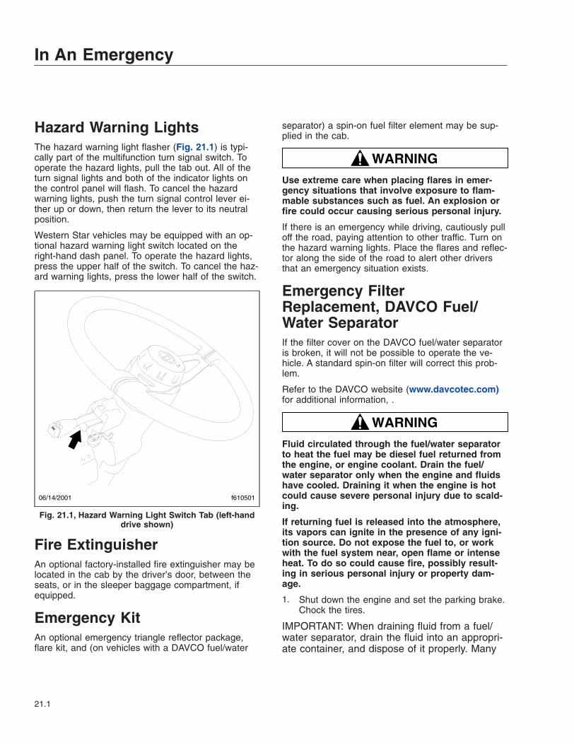
Hazard Warning LightsThe hazard warning light flasher (Fig. 21.1) is typi-cally part of the multifunction turn signal switch. Tooperate the hazard lights, pull the tab out. All of theturn signal lights and both of the indicator lights onthe control panel will flash. To cancel the hazardwarning lights, push the turn signal control lever ei-ther up or down, then return the lever to its neutralposition.
Western Star vehicles may be equipped with an op-tional hazard warning light switch located on theright-hand dash panel. To operate the hazard lights,press the upper half of the switch. To cancel the haz-ard warning lights, press the lower half of the switch.
Fire ExtinguisherAn optional factory-installed fire extinguisher may belocated in the cab by the driver’s door, between theseats, or in the sleeper baggage compartment, ifequipped.
Emergency KitAn optional emergency triangle reflector package,flare kit, and (on vehicles with a DAVCO fuel/water
separator) a spin-on fuel filter element may be sup-plied in the cab.
WARNINGUse extreme care when placing flares in emer-gency situations that involve exposure to flam-mable substances such as fuel. An explosion orfire could occur causing serious personal injury.
If there is an emergency while driving, cautiously pulloff the road, paying attention to other traffic. Turn onthe hazard warning lights. Place the flares and reflec-tor along the side of the road to alert other driversthat an emergency situation exists.
Emergency FilterReplacement, DAVCO Fuel/Water SeparatorIf the filter cover on the DAVCO fuel/water separatoris broken, it will not be possible to operate the ve-hicle. A standard spin-on filter will correct this prob-lem.
Refer to the DAVCO website (www.davcotec.com)for additional information, .
WARNINGFluid circulated through the fuel/water separatorto heat the fuel may be diesel fuel returned fromthe engine, or engine coolant. Drain the fuel/water separator only when the engine and fluidshave cooled. Draining it when the engine is hotcould cause severe personal injury due to scald-ing.
If returning fuel is released into the atmosphere,its vapors can ignite in the presence of any igni-tion source. Do not expose the fuel to, or workwith the fuel system near, open flame or intenseheat. To do so could cause fire, possibly result-ing in serious personal injury or property dam-age.
1. Shut down the engine and set the parking brake.Chock the tires.
IMPORTANT: When draining fluid from a fuel/water separator, drain the fluid into an appropri-ate container, and dispose of it properly. Many
PUSH
FOR TELE
PULL
FOR TILT
06/14/2001 f610501
Fig. 21.1, Hazard Warning Light Switch Tab (left-handdrive shown)
In An Emergency
21.1
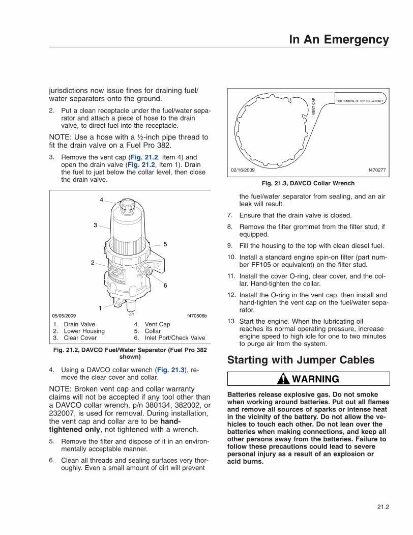
jurisdictions now issue fines for draining fuel/water separators onto the ground.
2. Put a clean receptacle under the fuel/water sepa-rator and attach a piece of hose to the drainvalve, to direct fuel into the receptacle.
NOTE: Use a hose with a ½-inch pipe thread tofit the drain valve on a Fuel Pro 382.
3. Remove the vent cap (Fig. 21.2, Item 4) andopen the drain valve (Fig. 21.2, Item 1). Drainthe fuel to just below the collar level, then closethe drain valve.
4. Using a DAVCO collar wrench (Fig. 21.3), re-move the clear cover and collar.
NOTE: Broken vent cap and collar warrantyclaims will not be accepted if any tool other thana DAVCO collar wrench, p/n 380134, 382002, or232007, is used for removal. During installation,the vent cap and collar are to be hand-tightened only, not tightened with a wrench.
5. Remove the filter and dispose of it in an environ-mentally acceptable manner.
6. Clean all threads and sealing surfaces very thor-oughly. Even a small amount of dirt will prevent
the fuel/water separator from sealing, and an airleak will result.
7. Ensure that the drain valve is closed.
8. Remove the filter grommet from the filter stud, ifequipped.
9. Fill the housing to the top with clean diesel fuel.
10. Install a standard engine spin-on filter (part num-ber FF105 or equivalent) on the filter stud.
11. Install the cover O-ring, clear cover, and the col-lar. Hand-tighten the collar.
12. Install the O-ring in the vent cap, then install andhand-tighten the vent cap on the fuel/water sepa-rator.
13. Start the engine. When the lubricating oilreaches its normal operating pressure, increaseengine speed to high idle for one to two minutesto purge air from the system.
Starting with Jumper Cables
WARNINGBatteries release explosive gas. Do not smokewhen working around batteries. Put out all flamesand remove all sources of sparks or intense heatin the vicinity of the battery. Do not allow the ve-hicles to touch each other. Do not lean over thebatteries when making connections, and keep allother persons away from the batteries. Failure tofollow these precautions could lead to severepersonal injury as a result of an explosion oracid burns.
f470506b05/05/2009
4
1
3
5
2
6
1. Drain Valve2. Lower Housing3. Clear Cover
4. Vent Cap5. Collar6. Inlet Port/Check Valve
Fig. 21.2, DAVCO Fuel/Water Separator (Fuel Pro 382shown)
02/16/2009 f470277
VE
NT
CA
P
FOR REMOVAL OF TOP COLLAR ONLY
Fig. 21.3, DAVCO Collar Wrench
In An Emergency
21.2

NOTICEMake sure both electrical systems are the samevoltage. Electronic devices on both vehicles canbe damaged when connected to a vehicle with adifferent operating voltage.
IMPORTANT: Do not attempt to jump start adamaged or frozen battery.
1. Set the parking brake and turn off all lights andother electrical devices. Ensure that the vehiclesare not touching and both ignition switches areturned to the OFF position.
2. Access the batteries by removing the battery boxcover, if equipped.
NOTICEAlways connect the batteries and jumper cablescorrectly (positive-to-positive and negative-to-negative). Connecting a charging device back-wards (positive-to-negative) can severely damagethe vehicle electrical content and cause non-warrantable failures.
IMPORTANT: On vehicles equipped with op-tional jump start posts, connect to these postsinstead of the battery terminals. Jump startposts may be installed in various locations onthe vehicle. See Fig. 21.4.
3. Connect the positive (+) jumper cable to thepositive terminal or jump start post on the dis-charged battery. See Fig. 21.5.
4. Connect the other end of the positive jumpercable to the positive terminal or jump start poston the booster battery providing the charge.
WARNINGDo the next step exactly as instructed and do notallow the clamps of one cable to touch theclamps of the other cable. Otherwise, a sparkcould occur near a battery, possibly resulting insevere personal injury from explosion or acidburns.
5. Connect the negative (-) jumper cable to thenegative terminal or jump start post on thebooster battery.
6. Connect the other end of the negative jumpercable to the negative ground stud on the vehiclerequiring the jump start.
7. Start the engine of the vehicle providing the jumpstart and let the engine run a few minutes tocharge the batteries of the other vehicle.
8. Attempt to start the engine of the vehicle receiv-ing the jump. Do not operate the starter longerthan 30 seconds, and wait at least two minutesbetween starting attempts to allow the starter tocool.
9. When the engine starts, let it idle a few minutes.
WARNINGDo the next step exactly as instructed and do notallow the clamps of one cable to touch theclamps of the other cable. Otherwise, a sparkcould occur near a battery, possibly resulting insevere personal injury from explosion or acidburns.
10. Disconnect the negative jumper cable from thejump started vehicle.
11. Disconnect the negative jumper cable from thevehicle that provided the jump start.
NEG JUMP
START STUD
POS JUMPSTART STUD
01/07/2011 f545726
1
2
3
1. Frame Rail2. Negative Jump Start Post3. Positive Jump Start Post
Fig. 21.4, Possible Jump Start Post Location(passenger-side engine compartment)
In An Emergency
21.3
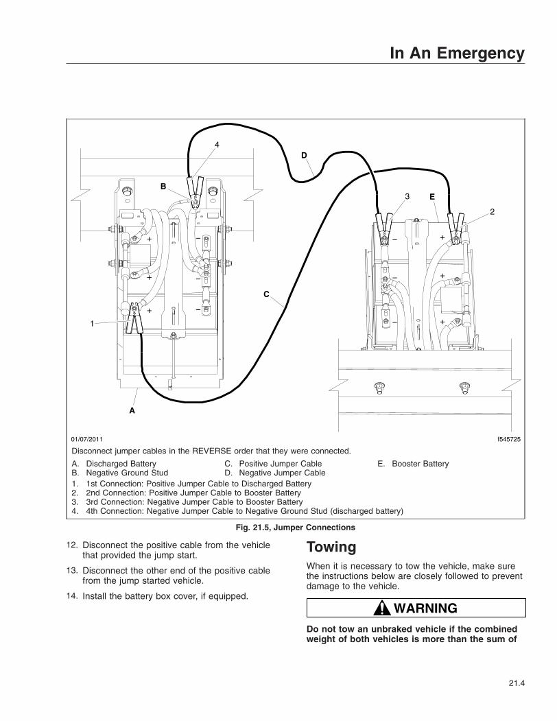
12. Disconnect the positive cable from the vehiclethat provided the jump start.
13. Disconnect the other end of the positive cablefrom the jump started vehicle.
14. Install the battery box cover, if equipped.
TowingWhen it is necessary to tow the vehicle, make surethe instructions below are closely followed to preventdamage to the vehicle.
WARNINGDo not tow an unbraked vehicle if the combinedweight of both vehicles is more than the sum of
01/07/2011 f545725
1
2
3
4
A
C
EB
D
−−
−
−
+
+
+
+
+
+
−
−
Disconnect jumper cables in the REVERSE order that they were connected.
A. Discharged BatteryB. Negative Ground Stud
C. Positive Jumper CableD. Negative Jumper Cable
E. Booster Battery
1. 1st Connection: Positive Jumper Cable to Discharged Battery2. 2nd Connection: Positive Jumper Cable to Booster Battery3. 3rd Connection: Negative Jumper Cable to Booster Battery4. 4th Connection: Negative Jumper Cable to Negative Ground Stud (discharged battery)
Fig. 21.5, Jumper Connections
In An Emergency
21.4
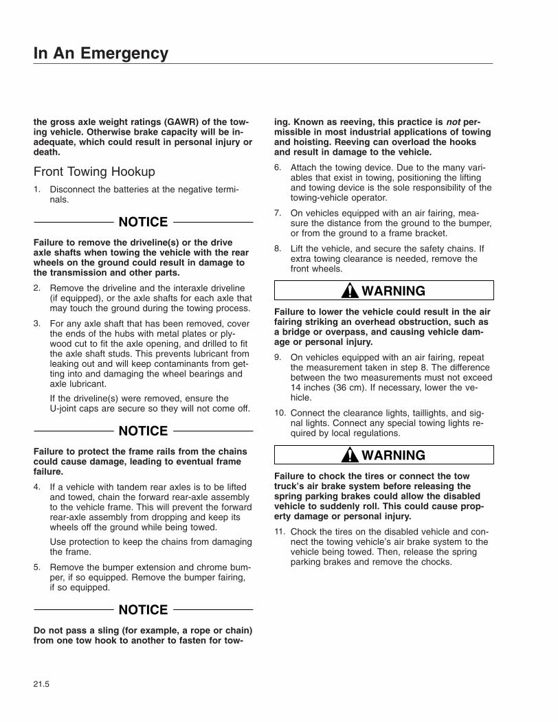
the gross axle weight ratings (GAWR) of the tow-ing vehicle. Otherwise brake capacity will be in-adequate, which could result in personal injury ordeath.
Front Towing Hookup1. Disconnect the batteries at the negative termi-
nals.
NOTICEFailure to remove the driveline(s) or the driveaxle shafts when towing the vehicle with the rearwheels on the ground could result in damage tothe transmission and other parts.
2. Remove the driveline and the interaxle driveline(if equipped), or the axle shafts for each axle thatmay touch the ground during the towing process.
3. For any axle shaft that has been removed, coverthe ends of the hubs with metal plates or ply-wood cut to fit the axle opening, and drilled to fitthe axle shaft studs. This prevents lubricant fromleaking out and will keep contaminants from get-ting into and damaging the wheel bearings andaxle lubricant.
If the driveline(s) were removed, ensure theU-joint caps are secure so they will not come off.
NOTICEFailure to protect the frame rails from the chainscould cause damage, leading to eventual framefailure.
4. If a vehicle with tandem rear axles is to be liftedand towed, chain the forward rear-axle assemblyto the vehicle frame. This will prevent the forwardrear-axle assembly from dropping and keep itswheels off the ground while being towed.
Use protection to keep the chains from damagingthe frame.
5. Remove the bumper extension and chrome bum-per, if so equipped. Remove the bumper fairing,if so equipped.
NOTICEDo not pass a sling (for example, a rope or chain)from one tow hook to another to fasten for tow-
ing. Known as reeving, this practice is not per-missible in most industrial applications of towingand hoisting. Reeving can overload the hooksand result in damage to the vehicle.
6. Attach the towing device. Due to the many vari-ables that exist in towing, positioning the liftingand towing device is the sole responsibility of thetowing-vehicle operator.
7. On vehicles equipped with an air fairing, mea-sure the distance from the ground to the bumper,or from the ground to a frame bracket.
8. Lift the vehicle, and secure the safety chains. Ifextra towing clearance is needed, remove thefront wheels.
WARNINGFailure to lower the vehicle could result in the airfairing striking an overhead obstruction, such asa bridge or overpass, and causing vehicle dam-age or personal injury.
9. On vehicles equipped with an air fairing, repeatthe measurement taken in step 8. The differencebetween the two measurements must not exceed14 inches (36 cm). If necessary, lower the ve-hicle.
10. Connect the clearance lights, taillights, and sig-nal lights. Connect any special towing lights re-quired by local regulations.
WARNINGFailure to chock the tires or connect the towtruck’s air brake system before releasing thespring parking brakes could allow the disabledvehicle to suddenly roll. This could cause prop-erty damage or personal injury.
11. Chock the tires on the disabled vehicle and con-nect the towing vehicle’s air brake system to thevehicle being towed. Then, release the springparking brakes and remove the chocks.
In An Emergency
21.5
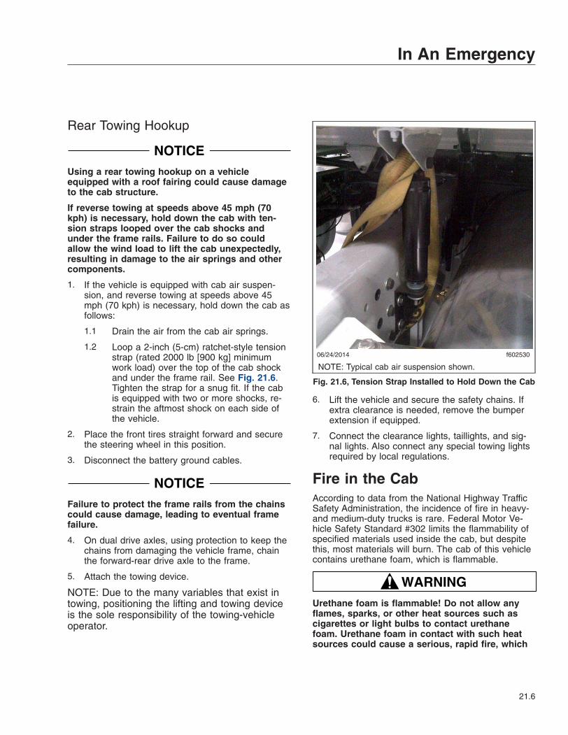
Rear Towing Hookup
NOTICEUsing a rear towing hookup on a vehicleequipped with a roof fairing could cause damageto the cab structure.
If reverse towing at speeds above 45 mph (70kph) is necessary, hold down the cab with ten-sion straps looped over the cab shocks andunder the frame rails. Failure to do so couldallow the wind load to lift the cab unexpectedly,resulting in damage to the air springs and othercomponents.
1. If the vehicle is equipped with cab air suspen-sion, and reverse towing at speeds above 45mph (70 kph) is necessary, hold down the cab asfollows:
1.1 Drain the air from the cab air springs.
1.2 Loop a 2-inch (5-cm) ratchet-style tensionstrap (rated 2000 lb [900 kg] minimumwork load) over the top of the cab shockand under the frame rail. See Fig. 21.6.Tighten the strap for a snug fit. If the cabis equipped with two or more shocks, re-strain the aftmost shock on each side ofthe vehicle.
2. Place the front tires straight forward and securethe steering wheel in this position.
3. Disconnect the battery ground cables.
NOTICEFailure to protect the frame rails from the chainscould cause damage, leading to eventual framefailure.
4. On dual drive axles, using protection to keep thechains from damaging the vehicle frame, chainthe forward-rear drive axle to the frame.
5. Attach the towing device.
NOTE: Due to the many variables that exist intowing, positioning the lifting and towing deviceis the sole responsibility of the towing-vehicleoperator.
6. Lift the vehicle and secure the safety chains. Ifextra clearance is needed, remove the bumperextension if equipped.
7. Connect the clearance lights, taillights, and sig-nal lights. Also connect any special towing lightsrequired by local regulations.
Fire in the CabAccording to data from the National Highway TrafficSafety Administration, the incidence of fire in heavy-and medium-duty trucks is rare. Federal Motor Ve-hicle Safety Standard #302 limits the flammability ofspecified materials used inside the cab, but despitethis, most materials will burn. The cab of this vehiclecontains urethane foam, which is flammable.
WARNINGUrethane foam is flammable! Do not allow anyflames, sparks, or other heat sources such ascigarettes or light bulbs to contact urethanefoam. Urethane foam in contact with such heatsources could cause a serious, rapid fire, which
06/24/2014 f602530
NOTE: Typical cab air suspension shown.
Fig. 21.6, Tension Strap Installed to Hold Down the Cab
In An Emergency
21.6
could result in death, severe burns, or gas poi-soning, as well as damage to the vehicle.
In Case of a Cab FireAs quickly as possible, bring the vehicle to a safestop, apply the parking brake, turn off the ignition,and get out of the vehicle.
In An Emergency
21.7
22
Pre- and Post-TripChecklists
Periodic Inspections and Maintenance, General Information . . . . . . . . . . . . . . . . . . . . . . . . . . . . . . 22.1Checklists . . . . . . . . . . . . . . . . . . . . . . . . . . . . . . . . . . . . . . . . . . . . . . . . . . . . . . . . . . . . . . . . . . . . . . 22.1Fluids Added . . . . . . . . . . . . . . . . . . . . . . . . . . . . . . . . . . . . . . . . . . . . . . . . . . . . . . . . . . . . . . . . . . . . 22.2
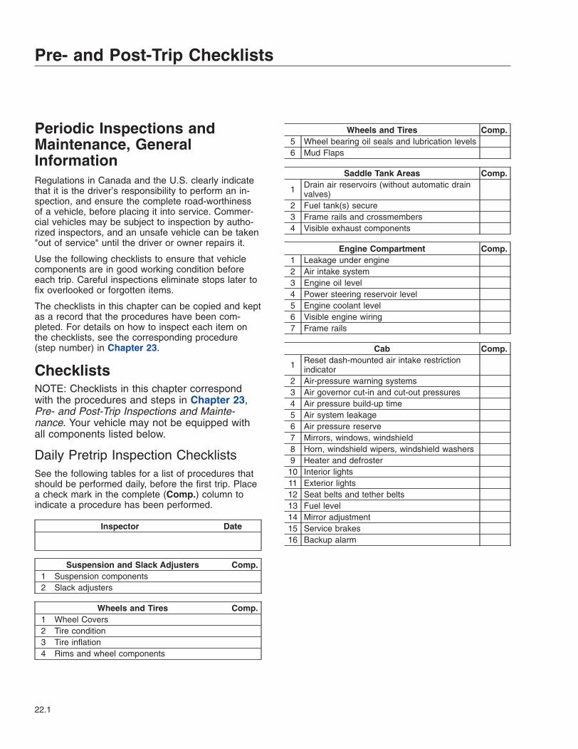
Periodic Inspections andMaintenance, GeneralInformationRegulations in Canada and the U.S. clearly indicatethat it is the driver’s responsibility to perform an in-spection, and ensure the complete road-worthinessof a vehicle, before placing it into service. Commer-cial vehicles may be subject to inspection by autho-rized inspectors, and an unsafe vehicle can be taken"out of service" until the driver or owner repairs it.
Use the following checklists to ensure that vehiclecomponents are in good working condition beforeeach trip. Careful inspections eliminate stops later tofix overlooked or forgotten items.
The checklists in this chapter can be copied and keptas a record that the procedures have been com-pleted. For details on how to inspect each item onthe checklists, see the corresponding procedure(step number) in Chapter 23.
ChecklistsNOTE: Checklists in this chapter correspondwith the procedures and steps in Chapter 23,Pre- and Post-Trip Inspections and Mainte-nance. Your vehicle may not be equipped withall components listed below.
Daily Pretrip Inspection ChecklistsSee the following tables for a list of procedures thatshould be performed daily, before the first trip. Placea check mark in the complete (Comp.) column toindicate a procedure has been performed.
Inspector Date
Suspension and Slack Adjusters Comp.1 Suspension components2 Slack adjusters
Wheels and Tires Comp.1 Wheel Covers2 Tire condition3 Tire inflation4 Rims and wheel components
Wheels and Tires Comp.5 Wheel bearing oil seals and lubrication levels6 Mud Flaps
Saddle Tank Areas Comp.
1 Drain air reservoirs (without automatic drainvalves)
2 Fuel tank(s) secure3 Frame rails and crossmembers4 Visible exhaust components
Engine Compartment Comp.1 Leakage under engine2 Air intake system3 Engine oil level4 Power steering reservoir level5 Engine coolant level6 Visible engine wiring7 Frame rails
Cab Comp.
1 Reset dash-mounted air intake restrictionindicator
2 Air-pressure warning systems3 Air governor cut-in and cut-out pressures4 Air pressure build-up time5 Air system leakage6 Air pressure reserve7 Mirrors, windows, windshield8 Horn, windshield wipers, windshield washers9 Heater and defroster10 Interior lights11 Exterior lights12 Seat belts and tether belts13 Fuel level14 Mirror adjustment15 Service brakes16 Backup alarm
Pre- and Post-Trip Checklists
22.1
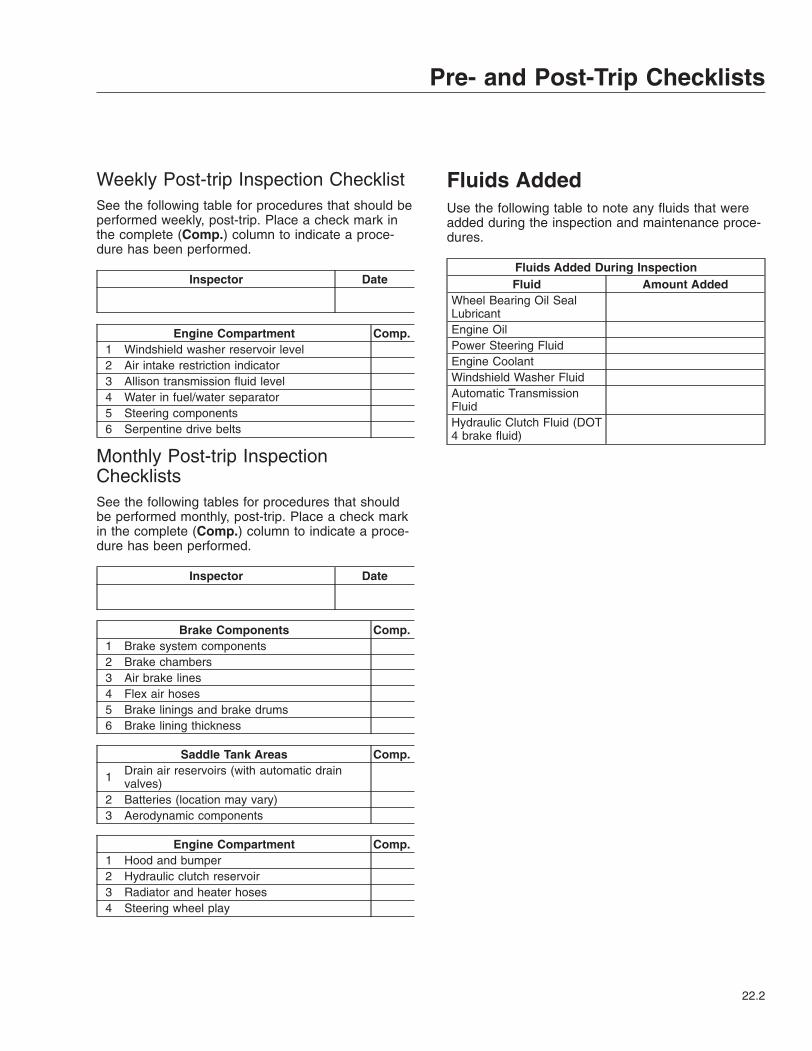
Weekly Post-trip Inspection ChecklistSee the following table for procedures that should beperformed weekly, post-trip. Place a check mark inthe complete (Comp.) column to indicate a proce-dure has been performed.
Inspector Date
Engine Compartment Comp.1 Windshield washer reservoir level2 Air intake restriction indicator3 Allison transmission fluid level4 Water in fuel/water separator5 Steering components6 Serpentine drive belts
Monthly Post-trip InspectionChecklistsSee the following tables for procedures that shouldbe performed monthly, post-trip. Place a check markin the complete (Comp.) column to indicate a proce-dure has been performed.
Inspector Date
Brake Components Comp.1 Brake system components2 Brake chambers3 Air brake lines4 Flex air hoses5 Brake linings and brake drums6 Brake lining thickness
Saddle Tank Areas Comp.
1 Drain air reservoirs (with automatic drainvalves)
2 Batteries (location may vary)3 Aerodynamic components
Engine Compartment Comp.1 Hood and bumper2 Hydraulic clutch reservoir3 Radiator and heater hoses4 Steering wheel play
Fluids AddedUse the following table to note any fluids that wereadded during the inspection and maintenance proce-dures.
Fluids Added During InspectionFluid Amount Added
Wheel Bearing Oil SealLubricantEngine OilPower Steering FluidEngine CoolantWindshield Washer FluidAutomatic TransmissionFluidHydraulic Clutch Fluid (DOT4 brake fluid)
Pre- and Post-Trip Checklists
22.2
23
Pre- and Post-TripInspections and
MaintenanceSafety Precautions . . . . . . . . . . . . . . . . . . . . . . . . . . . . . . . . . . . . . . . . . . . . . . . . . . . . . . . . . . . . . . . 23.1Daily Pretrip Inspections and Maintenance . . . . . . . . . . . . . . . . . . . . . . . . . . . . . . . . . . . . . . . . . . . . 23.1Weekly Post-Trip Inspections and Maintenance . . . . . . . . . . . . . . . . . . . . . . . . . . . . . . . . . . . . . . . . 23.9Monthly Post-Trip Inspections and Maintenance . . . . . . . . . . . . . . . . . . . . . . . . . . . . . . . . . . . . . . 23.12
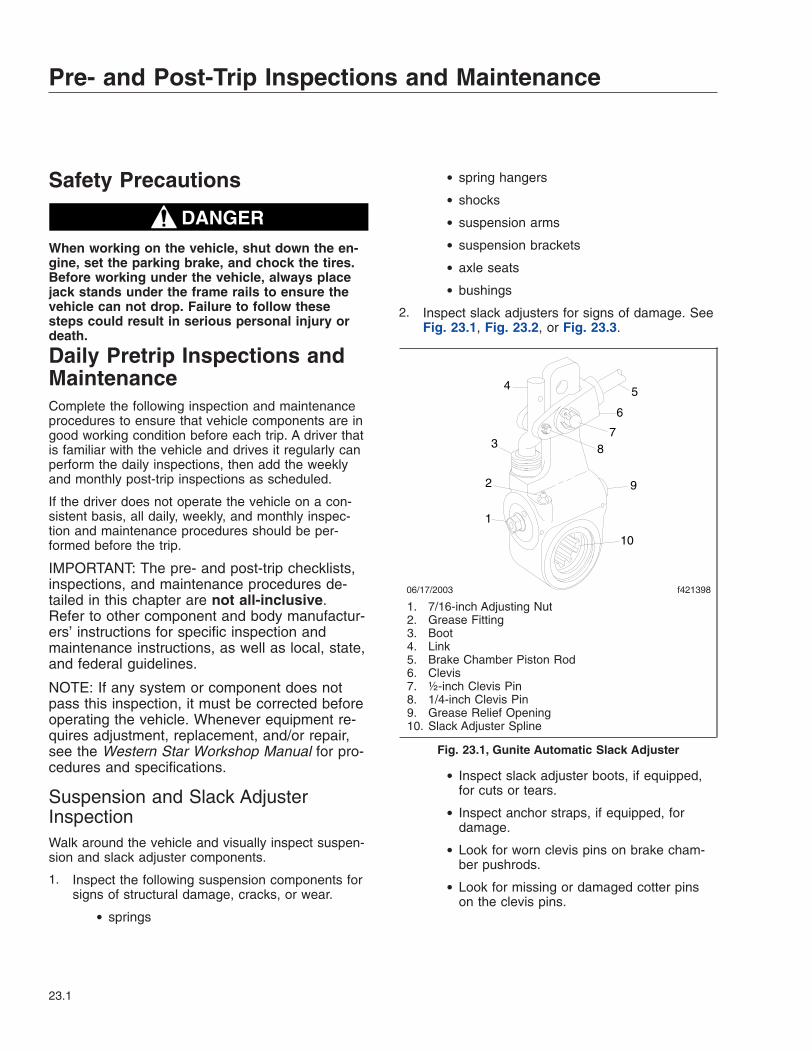
Safety Precautions
DANGERWhen working on the vehicle, shut down the en-gine, set the parking brake, and chock the tires.Before working under the vehicle, always placejack stands under the frame rails to ensure thevehicle can not drop. Failure to follow thesesteps could result in serious personal injury ordeath.
Daily Pretrip Inspections andMaintenanceComplete the following inspection and maintenanceprocedures to ensure that vehicle components are ingood working condition before each trip. A driver thatis familiar with the vehicle and drives it regularly canperform the daily inspections, then add the weeklyand monthly post-trip inspections as scheduled.
If the driver does not operate the vehicle on a con-sistent basis, all daily, weekly, and monthly inspec-tion and maintenance procedures should be per-formed before the trip.
IMPORTANT: The pre- and post-trip checklists,inspections, and maintenance procedures de-tailed in this chapter are not all-inclusive.Refer to other component and body manufactur-ers’ instructions for specific inspection andmaintenance instructions, as well as local, state,and federal guidelines.
NOTE: If any system or component does notpass this inspection, it must be corrected beforeoperating the vehicle. Whenever equipment re-quires adjustment, replacement, and/or repair,see the Western Star Workshop Manual for pro-cedures and specifications.
Suspension and Slack AdjusterInspectionWalk around the vehicle and visually inspect suspen-sion and slack adjuster components.
1. Inspect the following suspension components forsigns of structural damage, cracks, or wear.
• springs
• spring hangers
• shocks
• suspension arms
• suspension brackets
• axle seats
• bushings
2. Inspect slack adjusters for signs of damage. SeeFig. 23.1, Fig. 23.2, or Fig. 23.3.
• Inspect slack adjuster boots, if equipped,for cuts or tears.
• Inspect anchor straps, if equipped, fordamage.
• Look for worn clevis pins on brake cham-ber pushrods.
• Look for missing or damaged cotter pinson the clevis pins.
f42139806/17/2003
1
2
3
4 5
6
78
10
9
1. 7/16-inch Adjusting Nut2. Grease Fitting3. Boot4. Link5. Brake Chamber Piston Rod6. Clevis7. ½-inch Clevis Pin8. 1/4-inch Clevis Pin9. Grease Relief Opening10. Slack Adjuster Spline
Fig. 23.1, Gunite Automatic Slack Adjuster
Pre- and Post-Trip Inspections and Maintenance
23.1
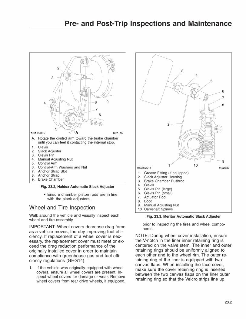
• Ensure chamber piston rods are in linewith the slack adjusters.
Wheel and Tire InspectionWalk around the vehicle and visually inspect eachwheel and tire assembly.
IMPORTANT: Wheel covers decrease drag forceas a vehicle moves, thereby improving fuel effi-ciency. If replacement of a wheel cover is nec-essary, the replacement cover must meet or ex-ceed the drag reduction performance of theoriginally installed cover in order to maintaincompliance with greenhouse gas and fuel effi-ciency regulations (GHG14).
1. If the vehicle was originally equipped with wheelcovers, ensure all wheel covers are present. In-spect wheel covers for damage or wear. Removewheel covers from rear drive wheels, if equipped,
prior to inspecting the tires and wheel compo-nents.
NOTE: During wheel cover installation, ensurethe V-notch in the liner inner retaining ring iscentered on the valve stem. The inner and outerretaining rings should be uniformly aligned toeach other and to the wheel rim. The outer re-taining ring of the liner is equipped with twocanvas flaps. When installing the face cover,make sure the cover retaining ring is insertedbetween the two canvas flaps on the liner outerretaining ring so that the Velcro strips line up
10/11/2005 f421397
1
2
3
4
5
6
7
8 9
A
A. Rotate the control arm toward the brake chamberuntil you can feel it contacting the internal stop.
1. Clevis2. Slack Adjuster3. Clevis Pin4. Manual Adjusting Nut5. Control Arm6. Control-Arm Washers and Nut7. Anchor Strap Slot8. Anchor Strap9. Brake Chamber
Fig. 23.2, Haldex Automatic Slack Adjuster
01/31/2011 f4225301
2
34
5
6
7
8
910
1. Grease Fitting (if equipped)2. Slack Adjuster Housing3. Brake Chamber Pushrod4. Clevis5. Clevis Pin (large)6. Clevis Pin (small)7. Actuator Rod8. Boot9. Manual Adjusting Nut10. Camshaft Splines
Fig. 23.3, Meritor Automatic Slack Adjuster
Pre- and Post-Trip Inspections and Maintenance
23.2
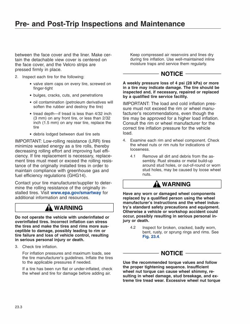
between the face cover and the liner. Make cer-tain the detachable view cover is centered onthe face cover, and the Velcro strips arepressed firmly in place.
2. Inspect each tire for the following:
• valve stem caps on every tire, screwed onfinger-tight
• bulges, cracks, cuts, and penetrations
• oil contamination (petroleum derivatives willsoften the rubber and destroy the tire)
• tread depth—if tread is less than 4/32 inch(3 mm) on any front tire, or less than 2/32inch (1.5 mm) on any rear tire, replace thetire
• debris lodged between duel tire sets
IMPORTANT: Low-rolling resistance (LRR) tiresminimize wasted energy as a tire rolls, therebydecreasing rolling effort and improving fuel effi-ciency. If tire replacement is necessary, replace-ment tires must meet or exceed the rolling resis-tance of the originally installed tires in order tomaintain compliance with greenhouse gas andfuel efficiency regulations (GHG14).
Contact your tire manufacturer/supplier to deter-mine the rolling resistance of the originally in-stalled tires. Visit www.epa.gov/smartway foradditional information and resources.
WARNINGDo not operate the vehicle with underinflated oroverinflated tires. Incorrect inflation can stressthe tires and make the tires and rims more sus-ceptible to damage, possibly leading to rim ortire failure and loss of vehicle control, resultingin serious personal injury or death.
3. Check tire inflation.
For inflation pressures and maximum loads, seethe tire manufacturer’s guidelines. Inflate the tiresto the applicable pressures if needed.
If a tire has been run flat or under-inflated, checkthe wheel and tire for damage before adding air.
Keep compressed air reservoirs and lines dryduring tire inflation. Use well-maintained inlinemoisture traps and service them regularly.
NOTICEA weekly pressure loss of 4 psi (28 kPa) or morein a tire may indicate damage. The tire should beinspected and, if necessary, repaired or replacedby a qualified tire service facility.
IMPORTANT: The load and cold inflation pres-sure must not exceed the rim or wheel manu-facturer’s recommendations, even though thetire may be approved for a higher load inflation.Consult the rim or wheel manufacturer for thecorrect tire inflation pressure for the vehicleload.
4. Examine each rim and wheel component. Checkthe wheel nuts or rim nuts for indications oflooseness.
4.1 Remove all dirt and debris from the as-sembly. Rust streaks or metal build-uparound stud holes, or out-of-round or wornstud holes, may be caused by loose wheelnuts.
WARNINGHave any worn or damaged wheel componentsreplaced by a qualified person using the wheelmanufacturer’s instructions and the wheel indus-try’s standard safety precautions and equipment.Otherwise a vehicle or workshop accident couldoccur, possibly resulting in serious personal in-jury or death.
4.2 Inspect for broken, cracked, badly worn,bent, rusty, or sprung rings and rims. SeeFig. 23.4.
NOTICEUse the recommended torque values and followthe proper tightening sequence. Insufficientwheel nut torque can cause wheel shimmy, re-sulting in wheel damage, stud breakage, and ex-treme tire tread wear. Excessive wheel nut torque
Pre- and Post-Trip Inspections and Maintenance
23.3
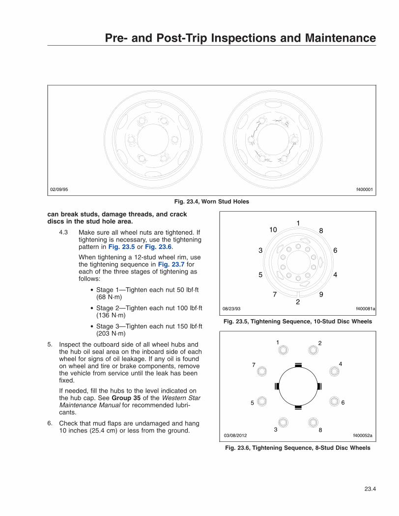
can break studs, damage threads, and crackdiscs in the stud hole area.
4.3 Make sure all wheel nuts are tightened. Iftightening is necessary, use the tighteningpattern in Fig. 23.5 or Fig. 23.6.
When tightening a 12-stud wheel rim, usethe tightening sequence in Fig. 23.7 foreach of the three stages of tightening asfollows:
• Stage 1—Tighten each nut 50 lbf·ft(68 N·m)
• Stage 2—Tighten each nut 100 lbf·ft(136 N·m)
• Stage 3—Tighten each nut 150 lbf·ft(203 N·m)
5. Inspect the outboard side of all wheel hubs andthe hub oil seal area on the inboard side of eachwheel for signs of oil leakage. If any oil is foundon wheel and tire or brake components, removethe vehicle from service until the leak has beenfixed.
If needed, fill the hubs to the level indicated onthe hub cap. See Group 35 of the Western StarMaintenance Manual for recommended lubri-cants.
6. Check that mud flaps are undamaged and hang10 inches (25.4 cm) or less from the ground.
02/09/95 f400001
Fig. 23.4, Worn Stud Holes
1
2
3
45
6
7
8
9
10
f400081a08/23/93
Fig. 23.5, Tightening Sequence, 10-Stud Disc Wheels
f400052a
1 2
3
4
5 6
7
803/08/2012
Fig. 23.6, Tightening Sequence, 8-Stud Disc Wheels
Pre- and Post-Trip Inspections and Maintenance
23.4

Saddle Tank Areas Inspection
WARNINGWhen draining the air reservoir, do not look intothe air jets or direct them toward anyone. Dirt orsludge particles may be in the airstream andcould cause injury.
NOTICEIf the water drained from the air reservoirs iscloudy or oily, it may indicate a problem with thecompressor. If oil is allowed to contaminate theair dryer, it will not remove the water from the airbrake system, which could adversely affect brak-ing.
1. Drain the brake system air reservoirs (reservoirswithout automatic drain valves only).
WARNINGNever operate the engine with the fuel tank shut-off valves partially closed. This could damage thefuel pump, causing sudden loss of engine power,possibly resulting in serious personal injury dueto reduced vehicle control.
2. Ensure fuel tanks are secured to their mountingbrackets and that the mounting brackets are se-cured to the frame.
If equipped with fuel tank shutoff valves, be surethe valves are fully open.
3. Inspect visible frame rails for missing bolts, shinyareas, or rust streaks. Check all visible cross-members for damage or signs of looseness.
4. Inspect visible components of the exhaust sys-tem to ensure connections are tight.
Inspect upstream of the aftertreatment device(ATD), if equipped, for cracking or signs of leaks,such as soot trails. Inspect downstream of theATD for signs of exhaust leaks, such as blister-ing or warping of nearby components.
Engine Compartment Inspection1. Check the ground underneath the engine for fuel,
oil, or coolant leaks.
2. Inspect the air intake system for leaks or dam-age.
NOTICEFailure to maintain a sealed air intake systemcould allow the entry of dirt and contaminantsinto the engine. This could adversely affect en-gine performance and result in engine damage.
2.1 Push the reset button on the air intakerestriction indicator located on the aircleaner, if equipped.
2.2 Check the air intake duct from the aircleaner to the engine intake. Make surethe duct components are secure and air-tight.
2.3 Check the vacuator (spitter) valve(s) fordamage, and make sure the lips of thevalve(s) are pliable and free of debris.
3. Check the engine oil level.
NOTICEOperating the engine with the oil level below theminimum fill (or "add") mark or above the maxi-mum fill (or "full") mark could result in enginedamage.
3.1 Check the oil level with the vehicle parkedon a level surface. See the engine manu-facturer’s guidelines for engine shutdowntime requirements prior to checking the oillevel.
02/02/2012 f400364
18
10
4
6
122
7
9
3
11
5
Fig. 23.7, Tightening Sequence, 12-Stud Wheel Rims
Pre- and Post-Trip Inspections and Maintenance
23.5
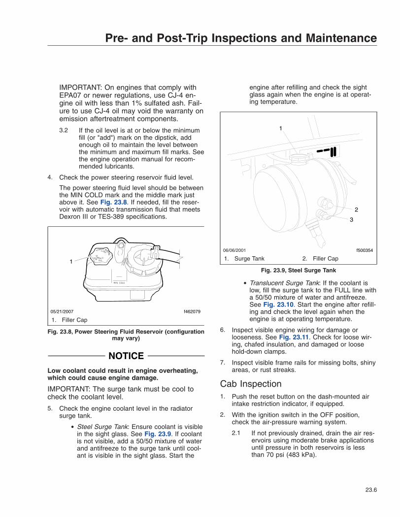
IMPORTANT: On engines that comply withEPA07 or newer regulations, use CJ-4 en-gine oil with less than 1% sulfated ash. Fail-ure to use CJ-4 oil may void the warranty onemission aftertreatment components.
3.2 If the oil level is at or below the minimumfill (or "add") mark on the dipstick, addenough oil to maintain the level betweenthe minimum and maximum fill marks. Seethe engine operation manual for recom-mended lubricants.
4. Check the power steering reservoir fluid level.
The power steering fluid level should be betweenthe MIN COLD mark and the middle mark justabove it. See Fig. 23.8. If needed, fill the reser-voir with automatic transmission fluid that meetsDexron III or TES-389 specifications.
NOTICELow coolant could result in engine overheating,which could cause engine damage.
IMPORTANT: The surge tank must be cool tocheck the coolant level.
5. Check the engine coolant level in the radiatorsurge tank.
• Steel Surge Tank: Ensure coolant is visiblein the sight glass. See Fig. 23.9. If coolantis not visible, add a 50/50 mixture of waterand antifreeze to the surge tank until cool-ant is visible in the sight glass. Start the
engine after refilling and check the sightglass again when the engine is at operat-ing temperature.
• Translucent Surge Tank: If the coolant islow, fill the surge tank to the FULL line witha 50/50 mixture of water and antifreeze.See Fig. 23.10. Start the engine after refill-ing and check the level again when theengine is at operating temperature.
6. Inspect visible engine wiring for damage orlooseness. See Fig. 23.11. Check for loose wir-ing, chafed insulation, and damaged or loosehold-down clamps.
7. Inspect visible frame rails for missing bolts, shinyareas, or rust streaks.
Cab Inspection1. Push the reset button on the dash-mounted air
intake restriction indicator, if equipped.
2. With the ignition switch in the OFF position,check the air-pressure warning system.
2.1 If not previously drained, drain the air res-ervoirs using moderate brake applicationsuntil pressure in both reservoirs is lessthan 70 psi (483 kPa).
05/21/2007
1
f462079
1. Filler Cap
Fig. 23.8, Power Steering Fluid Reservoir (configurationmay vary)
06/06/2001
1
2
3
f500354
1. Surge Tank 2. Filler Cap
Fig. 23.9, Steel Surge Tank
Pre- and Post-Trip Inspections and Maintenance
23.6
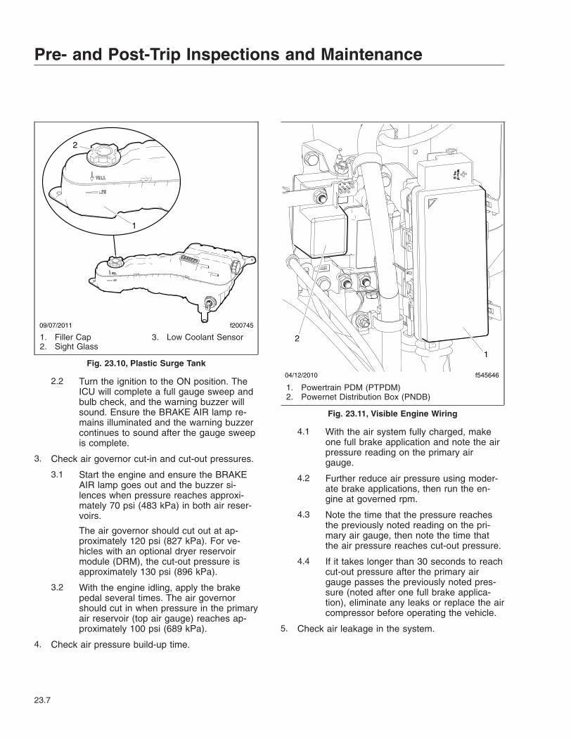
2.2 Turn the ignition to the ON position. TheICU will complete a full gauge sweep andbulb check, and the warning buzzer willsound. Ensure the BRAKE AIR lamp re-mains illuminated and the warning buzzercontinues to sound after the gauge sweepis complete.
3. Check air governor cut-in and cut-out pressures.
3.1 Start the engine and ensure the BRAKEAIR lamp goes out and the buzzer si-lences when pressure reaches approxi-mately 70 psi (483 kPa) in both air reser-voirs.
The air governor should cut out at ap-proximately 120 psi (827 kPa). For ve-hicles with an optional dryer reservoirmodule (DRM), the cut-out pressure isapproximately 130 psi (896 kPa).
3.2 With the engine idling, apply the brakepedal several times. The air governorshould cut in when pressure in the primaryair reservoir (top air gauge) reaches ap-proximately 100 psi (689 kPa).
4. Check air pressure build-up time.
4.1 With the air system fully charged, makeone full brake application and note the airpressure reading on the primary airgauge.
4.2 Further reduce air pressure using moder-ate brake applications, then run the en-gine at governed rpm.
4.3 Note the time that the pressure reachesthe previously noted reading on the pri-mary air gauge, then note the time thatthe air pressure reaches cut-out pressure.
4.4 If it takes longer than 30 seconds to reachcut-out pressure after the primary airgauge passes the previously noted pres-sure (noted after one full brake applica-tion), eliminate any leaks or replace the aircompressor before operating the vehicle.
5. Check air leakage in the system.
09/07/2011 f200745
2
1
1. Filler Cap2. Sight Glass
3. Low Coolant Sensor
Fig. 23.10, Plastic Surge Tank04/12/2010 f545646
1
2
1. Powertrain PDM (PTPDM)2. Powernet Distribution Box (PNDB)
Fig. 23.11, Visible Engine Wiring
Pre- and Post-Trip Inspections and Maintenance
23.7
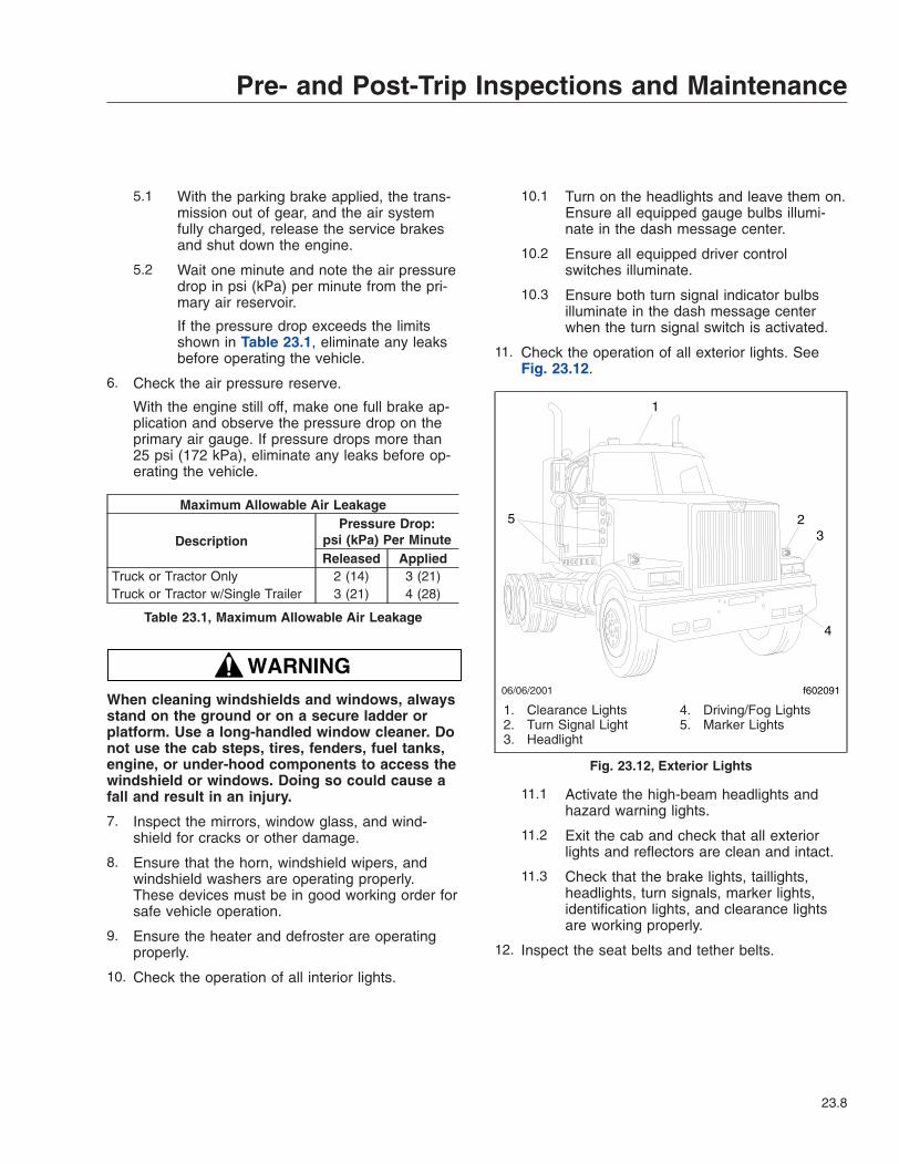
5.1 With the parking brake applied, the trans-mission out of gear, and the air systemfully charged, release the service brakesand shut down the engine.
5.2 Wait one minute and note the air pressuredrop in psi (kPa) per minute from the pri-mary air reservoir.
If the pressure drop exceeds the limitsshown in Table 23.1, eliminate any leaksbefore operating the vehicle.
6. Check the air pressure reserve.
With the engine still off, make one full brake ap-plication and observe the pressure drop on theprimary air gauge. If pressure drops more than25 psi (172 kPa), eliminate any leaks before op-erating the vehicle.
Maximum Allowable Air Leakage
DescriptionPressure Drop:
psi (kPa) Per MinuteReleased Applied
Truck or Tractor Only 2 (14) 3 (21)Truck or Tractor w/Single Trailer 3 (21) 4 (28)
Table 23.1, Maximum Allowable Air Leakage
WARNINGWhen cleaning windshields and windows, alwaysstand on the ground or on a secure ladder orplatform. Use a long-handled window cleaner. Donot use the cab steps, tires, fenders, fuel tanks,engine, or under-hood components to access thewindshield or windows. Doing so could cause afall and result in an injury.
7. Inspect the mirrors, window glass, and wind-shield for cracks or other damage.
8. Ensure that the horn, windshield wipers, andwindshield washers are operating properly.These devices must be in good working order forsafe vehicle operation.
9. Ensure the heater and defroster are operatingproperly.
10. Check the operation of all interior lights.
10.1 Turn on the headlights and leave them on.Ensure all equipped gauge bulbs illumi-nate in the dash message center.
10.2 Ensure all equipped driver controlswitches illuminate.
10.3 Ensure both turn signal indicator bulbsilluminate in the dash message centerwhen the turn signal switch is activated.
11. Check the operation of all exterior lights. SeeFig. 23.12.
11.1 Activate the high-beam headlights andhazard warning lights.
11.2 Exit the cab and check that all exteriorlights and reflectors are clean and intact.
11.3 Check that the brake lights, taillights,headlights, turn signals, marker lights,identification lights, and clearance lightsare working properly.
12. Inspect the seat belts and tether belts.
06/06/2001
1
23
4
5
f602091
1. Clearance Lights2. Turn Signal Light3. Headlight
4. Driving/Fog Lights5. Marker Lights
Fig. 23.12, Exterior Lights
Pre- and Post-Trip Inspections and Maintenance
23.8

WARNINGInspect and maintain seat belts. When any part ofa seat belt system needs replacement, the entireseat belt must be replaced, both retractor andbuckle side. Any time a vehicle is involved in anaccident, and the seat belt system was in use,the entire vehicle seat belt system must be re-placed before operating the vehicle. Do not at-tempt to modify the seat belt system; doing socould change the effectiveness of the system.Failure to replace worn or damaged seat belts, ormaking any modifications to the system, may re-sult in personal injury or death.
12.1 Check the web for fraying, cuts, extremedirt and dust, or for severe fading fromexposure to sunlight, especially near thebuckle latch plate and in the D-loop guidearea.
12.2 Check operation of the buckle, latch, Kom-fort Latch or Sliding Komfort Latch (ifequipped), web retractor, and upper seatbelt mount on the door pillar. Check allvisible components for wear or damage.
12.3 Check the seat belt and tether belt con-nection points and tighten any that areloose.
WARNINGNever fill fuel tanks to more than 95 percent oftheir liquid capacity. This could make them morelikely to rupture from impact, possibly causingfire and resulting in serious personal injury ordeath by burning.
Do not mix gasoline or alcohol with diesel fuel.This mixture could cause an explosion, possiblyresulting in serious personal injury or death. Donot fill the fuel tanks in the presence of sparks,open flames, or intense heat. These could ignitethe fuel, possibly causing severe burns.
IMPORTANT: On engines that comply withEPA07 or newer regulations, use ultralow-sulfurdiesel (ULSD) with 15 ppm sulfur content orless. Failure to use ULSD fuel may void thewarranty on emission components.
13. Check the fuel level in the fuel tank(s). To keepcondensation to a minimum, fuel tanks should befilled at the end of each day.
14. Adjust the rearview and down view mirrors asnecessary.
15. Test the service brakes.
15.1 With the engine running and air systemfully charged, set the parking brake.
15.2 Put the vehicle in the lowest gear andgently attempt to move it forward. The ve-hicle should not move.
If the vehicle moves, the parking brakesare not operating correctly and must berepaired before the vehicle is operated.
16. Test the backup alarm
16.1 Release the parking brake and put thetransmission in reverse.
16.2 Move the vehicle slightly backward to en-sure that the backup alarm is operatingcorrectly.
Weekly Post-Trip Inspectionsand MaintenanceEngine Compartment Inspection
WARNINGWasher fluids may be flammable and poisonous.Do not expose washer fluid to an open flame orany burning material, such as a cigarette. Alwayscomply with the washer fluid manufacturer’s rec-ommended safety precautions.
1. Check the windshield washer reservoir fluid level.The reservoir is usually located near the right-hand frame rail.
2. After resetting the air intake restriction indicatorduring the daily pretrip inspection, check the indi-cator again with the engine off.
2.1 Check an indicator with graduations to seeif air restriction exceeds the value shownin Table 23.2.
Check a go/no-go indicator without gradu-ations to see if the colored bar showsthrough the clear window.
Pre- and Post-Trip Inspections and Maintenance
23.9
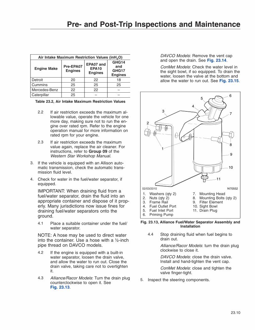
Air Intake Maximum Restriction Values (inH2O)
Engine Make Pre-EPA07Engines
EPA07 andEPA10
Engines
GHG14and
GHG17Engines
Detroit 20 22 18Cummins 25 25 25Mercedes-Benz 22 22 –Caterpillar 25 – –
Table 23.2, Air Intake Maximum Restriction Values
2.2 If air restriction exceeds the maximum al-lowable value, operate the vehicle for onemore day, making sure not to run the en-gine over rated rpm. Refer to the engineoperation manual for more information onrated rpm for your engine.
2.3 If air restriction exceeds the maximumvalue again, replace the air cleaner. Forinstructions, refer to Group 09 of theWestern Star Workshop Manual.
3. If the vehicle is equipped with an Allison auto-matic transmission, check the automatic trans-mission fluid level.
4. Check for water in the fuel/water separator, ifequipped.
IMPORTANT: When draining fluid from afuel/water separator, drain the fluid into anappropriate container and dispose of it prop-erly. Many jurisdictions now issue fines fordraining fuel/water separators onto theground.
4.1 Place a suitable container under the fuel/water separator.
NOTE: A hose may be used to direct waterinto the container. Use a hose with a ½-inchpipe thread on DAVCO models.
4.2 If the engine is equipped with a built-inwater separator, loosen the drain valve,and allow the water to run out. Close thedrain valve, taking care not to overtightenit.
4.3 Alliance/Racor Models: Turn the drain plugcounterclockwise to open it. SeeFig. 23.13.
DAVCO Models: Remove the vent capand open the drain. See Fig. 23.14.
ConMet Models: Check the water level inthe sight bowl, if so equipped. To drain thewater, loosen the valve at the bottom andallow the water to run out. See Fig. 23.15.
4.4 Stop draining fluid when fuel begins todrain out.
Alliance/Racor Models: turn the drain plugclockwise to close it.
DAVCO Models: close the drain valve.Install and hand-tighten the vent cap.
ConMet Models: close and tighten thevalve finger-tight.
5. Inspect the steering components.
02/03/2010 f470552
1
2
34
56
7
8
9
10
11
1. Washers (qty 2)2. Nuts (qty 2)3. Frame Rail4. Fuel Outlet Port5. Fuel Inlet Port6. Priming Pump
7. Mounting Head8. Mounting Bolts (qty 2)9. Filter Element10. Sight Bowl11. Drain Plug
Fig. 23.13, Alliance Fuel/Water Separator Assembly andInstallation
Pre- and Post-Trip Inspections and Maintenance
23.10
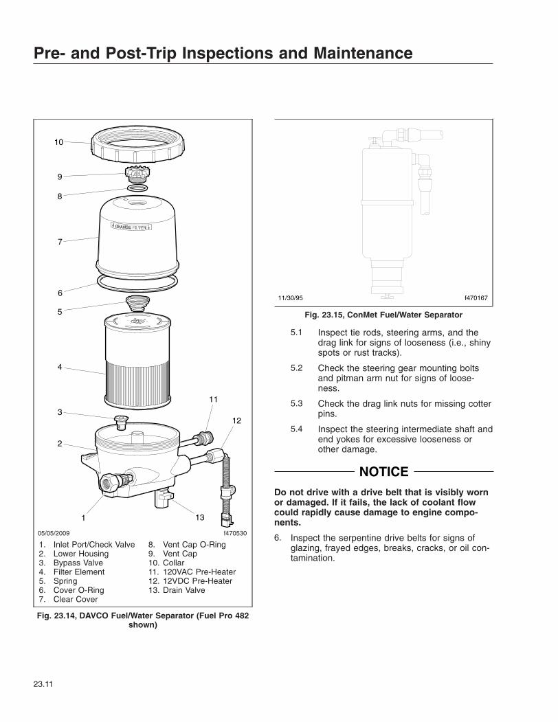
5.1 Inspect tie rods, steering arms, and thedrag link for signs of looseness (i.e., shinyspots or rust tracks).
5.2 Check the steering gear mounting boltsand pitman arm nut for signs of loose-ness.
5.3 Check the drag link nuts for missing cotterpins.
5.4 Inspect the steering intermediate shaft andend yokes for excessive looseness orother damage.
NOTICEDo not drive with a drive belt that is visibly wornor damaged. If it fails, the lack of coolant flowcould rapidly cause damage to engine compo-nents.
6. Inspect the serpentine drive belts for signs ofglazing, frayed edges, breaks, cracks, or oil con-tamination.
05/05/2009 f470530
1
2
3
4
5
6
7
8
9
10
11
12
13
1. Inlet Port/Check Valve2. Lower Housing3. Bypass Valve4. Filter Element5. Spring6. Cover O-Ring7. Clear Cover
8. Vent Cap O-Ring9. Vent Cap10. Collar11. 120VAC Pre-Heater12. 12VDC Pre-Heater13. Drain Valve
Fig. 23.14, DAVCO Fuel/Water Separator (Fuel Pro 482shown)
11/30/95 f470167
Fig. 23.15, ConMet Fuel/Water Separator
Pre- and Post-Trip Inspections and Maintenance
23.11
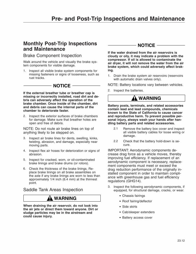
Monthly Post-Trip Inspectionsand MaintenanceBrake Component InspectionWalk around the vehicle and visually the brake sys-tem components for visible damage.
1. Inspect all visible brake system components formissing fasteners or signs of looseness, such asrust tracks.
NOTICEIf the external breather tube or breather cap ismissing or incorrectly installed, road dirt and de-bris can adversely affect the operation of thebrake chamber. Once inside of the chamber, dirtand debris can cause the internal parts of thechamber to deteriorate faster.
2. Inspect the exterior surfaces of brake chambersfor damage. Make sure that breather holes areopen and free of debris.
NOTE: Do not route air brake lines on top ofanything likely to be stepped on.
3. Inspect air brake lines for dents, swelling, kinks,twisting, abrasion, and damage, especially nearmoving parts.
4. Inspect flex air hoses for deterioration or signs ofabrasion.
5. Inspect for cracked, worn, or oil-contaminatedbrake linings and brake drums (or rotors).
6. Check the thickness of the brake linings. Re-place brake linings on all brake assemblies onthe axle if any brake linings are worn to less thanapproximately 1/4 inch (6.4 mm) at the thinnestpoint.
Saddle Tank Areas Inspection
WARNINGWhen draining the air reservoir, do not look intothe air jets or direct them toward anyone. Dirt orsludge particles may be in the airstream andcould cause injury.
NOTICEIf the water drained from the air reservoirs iscloudy or oily, it may indicate a problem with thecompressor. If oil is allowed to contaminate theair dryer, it will not remove the water from the airbrake system, which could adversely affect brak-ing.
1. Drain the brake system air reservoirs (reservoirswith automatic drain valves only).
NOTE: Battery locations vary between vehicles.
2. Inspect the batteries.
WARNINGBattery posts, terminals, and related accessoriescontain lead and lead compounds, chemicalsknown to the State of California to cause cancerand reproductive harm. To prevent possible per-sonal injury, always wash your hands after han-dling battery parts and related accessories.
2.1 Remove the battery box cover and inspectall visible battery cables for loose wiring ordamage.
2.2 Check that the battery hold-down is se-cure.
IMPORTANT: Aerodynamic components de-crease drag force as a vehicle moves, therebyimproving fuel efficiency. If replacement of anaerodynamic component is necessary, replace-ment components must meet or exceed thedrag reduction performance of the originally in-stalled component in order to maintain compli-ance with greenhouse gas and fuel efficiencyregulations (GHG14).
3. Inspect the following aerodynamic components, ifequipped, for structural damage, cracks, or wear.
• Chassis fairings
• Roof fairing/deflector
• Side skirts
• Cab/sleeper extenders
• Battery access cover
Pre- and Post-Trip Inspections and Maintenance
23.12
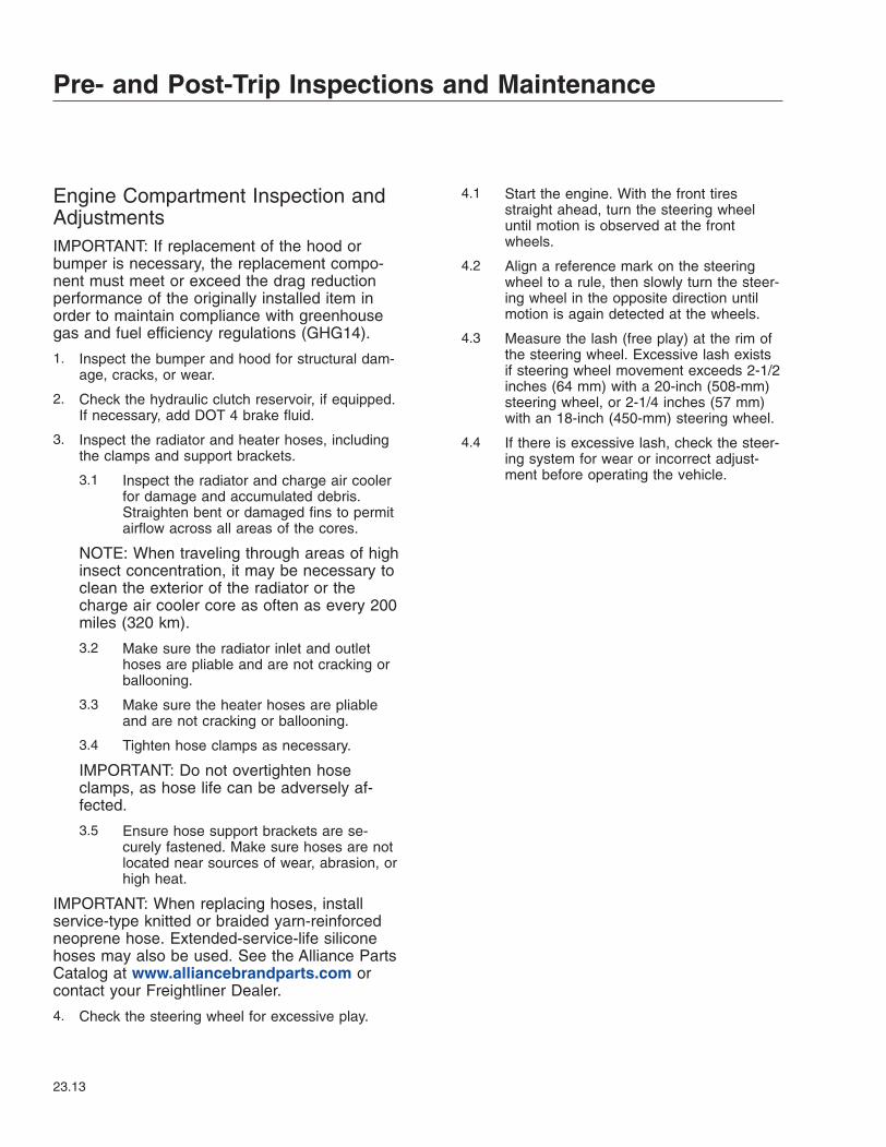
Engine Compartment Inspection andAdjustmentsIMPORTANT: If replacement of the hood orbumper is necessary, the replacement compo-nent must meet or exceed the drag reductionperformance of the originally installed item inorder to maintain compliance with greenhousegas and fuel efficiency regulations (GHG14).
1. Inspect the bumper and hood for structural dam-age, cracks, or wear.
2. Check the hydraulic clutch reservoir, if equipped.If necessary, add DOT 4 brake fluid.
3. Inspect the radiator and heater hoses, includingthe clamps and support brackets.
3.1 Inspect the radiator and charge air coolerfor damage and accumulated debris.Straighten bent or damaged fins to permitairflow across all areas of the cores.
NOTE: When traveling through areas of highinsect concentration, it may be necessary toclean the exterior of the radiator or thecharge air cooler core as often as every 200miles (320 km).
3.2 Make sure the radiator inlet and outlethoses are pliable and are not cracking orballooning.
3.3 Make sure the heater hoses are pliableand are not cracking or ballooning.
3.4 Tighten hose clamps as necessary.
IMPORTANT: Do not overtighten hoseclamps, as hose life can be adversely af-fected.
3.5 Ensure hose support brackets are se-curely fastened. Make sure hoses are notlocated near sources of wear, abrasion, orhigh heat.
IMPORTANT: When replacing hoses, installservice-type knitted or braided yarn-reinforcedneoprene hose. Extended-service-life siliconehoses may also be used. See the Alliance PartsCatalog at www.alliancebrandparts.com orcontact your Freightliner Dealer.
4. Check the steering wheel for excessive play.
4.1 Start the engine. With the front tiresstraight ahead, turn the steering wheeluntil motion is observed at the frontwheels.
4.2 Align a reference mark on the steeringwheel to a rule, then slowly turn the steer-ing wheel in the opposite direction untilmotion is again detected at the wheels.
4.3 Measure the lash (free play) at the rim ofthe steering wheel. Excessive lash existsif steering wheel movement exceeds 2-1/2inches (64 mm) with a 20-inch (508-mm)steering wheel, or 2-1/4 inches (57 mm)with an 18-inch (450-mm) steering wheel.
4.4 If there is excessive lash, check the steer-ing system for wear or incorrect adjust-ment before operating the vehicle.
Pre- and Post-Trip Inspections and Maintenance
23.13
Subject Page
AABTS Seat . . . . . . . . . . . . . . . . . . . . . . . . . . . . . 6.4
Armrest Adjustment . . . . . . . . . . . . . . . . . . . . . 6.5Backrest Adjustment . . . . . . . . . . . . . . . . . . . . . 6.5Cushion Extension
Adjustment . . . . . . . . . . . . . . . . . . . . . . . . . . 6.5Isolator . . . . . . . . . . . . . . . . . . . . . . . . . . . . . 6.5Lumbar Adjustment . . . . . . . . . . . . . . . . . . . . . 6.5Seat Height Adjustment . . . . . . . . . . . . . . . . . . 6.5Seat Tilt Control . . . . . . . . . . . . . . . . . . . . . . . 6.5Shoulder Belt Height Control . . . . . . . . . . . . . . . 6.5Track Adjustment . . . . . . . . . . . . . . . . . . . . . . . 6.5
Adjustable Steering ColumnControls . . . . . . . . . . . . . . . . . . . . . . . . . . . . . 4.13
Adjusting Headlight Aim . . . . . . . . . . . . . . . . . . . 19.1Air Brake System . . . . . . . . . . . . . . . . . . . . . . . . 12.1
Automatic Slack Adjusters . . . . . . . . . . . . . . . . 12.3Brake System Conditions . . . . . . . . . . . . . . . . 12.3Brake System Operation . . . . . . . . . . . . . . . . . 12.1General Information, Brake
System . . . . . . . . . . . . . . . . . . . . . . . . . . . 12.1Air-Suspension Dump Valve . . . . . . . . . . . . . . . . . 18.1Allison Automatic Transmissions . . . . . . . . . . . . . . 15.5
Allison TransmissionOperation . . . . . . . . . . . . . . . . . . . . . . . . . . 15.6
General Information, AllisonTransmissions . . . . . . . . . . . . . . . . . . . . . . . 15.5
Auxiliary Braking Applications . . . . . . . . . . . . . . . . 10.3Engine Brake . . . . . . . . . . . . . . . . . . . . . . . . 10.3Exhaust Brake . . . . . . . . . . . . . . . . . . . . . . . . 10.4
AWD Controls . . . . . . . . . . . . . . . . . . . . . . . . . . 4.11AWD Operation Switch . . . . . . . . . . . . . . . . . . 4.11Transfer Case Range Switch . . . . . . . . . . . . . . 4.11
BBack-of-Cab Access . . . . . . . . . . . . . . . . . . . . . . . 2.5
Accessing Back-of-Cab Area . . . . . . . . . . . . . . . 2.6Exiting Back-of-Cab Area . . . . . . . . . . . . . . . . . 2.6
Battery Access . . . . . . . . . . . . . . . . . . . . . . . . . . 8.3Battery Disconnect Switches . . . . . . . . . . . . . . . . . 8.2
Cab Load DisconnectSwitch, EPA10 and Newer . . . . . . . . . . . . . . . 8.2
Pre-EPA10 Battery IsolationSwitch . . . . . . . . . . . . . . . . . . . . . . . . . . . . . 8.2
Bostrom Seat . . . . . . . . . . . . . . . . . . . . . . . . . . . 6.3Backrest Tilt . . . . . . . . . . . . . . . . . . . . . . . . . . 6.3Bottom Cushion Tilt . . . . . . . . . . . . . . . . . . . . . 6.4Fore-and-Aft Seat Slide . . . . . . . . . . . . . . . . . . 6.4Height Adjustment . . . . . . . . . . . . . . . . . . . . . . 6.4Isolator . . . . . . . . . . . . . . . . . . . . . . . . . . . . . 6.4Lumbar Support . . . . . . . . . . . . . . . . . . . . . . . 6.3
Subject PageBrake Controls . . . . . . . . . . . . . . . . . . . . . . . . . 4.12
Antilock Braking System . . . . . . . . . . . . . . . . . 4.13Parking Brake Control Valve . . . . . . . . . . . . . . . 4.12Trailer Air Supply Valve . . . . . . . . . . . . . . . . . . 4.12Trailer Brake Lever . . . . . . . . . . . . . . . . . . . . . 4.12
CCab Amenities . . . . . . . . . . . . . . . . . . . . . . . . . . . 7.2
Cigar Lighter/Accessory Plug . . . . . . . . . . . . . . . 7.2Cup Holders . . . . . . . . . . . . . . . . . . . . . . . . . . 7.2Electronic Device Mount . . . . . . . . . . . . . . . . . . 7.3Glove Box . . . . . . . . . . . . . . . . . . . . . . . . . . . 7.2Lighting . . . . . . . . . . . . . . . . . . . . . . . . . . . . . 7.3Storage Areas . . . . . . . . . . . . . . . . . . . . . . . . . 7.3
Cab Climate Control Panels . . . . . . . . . . . . . . . . . . 5.1Controls . . . . . . . . . . . . . . . . . . . . . . . . . . . . . 5.1Modes . . . . . . . . . . . . . . . . . . . . . . . . . . . . . . 5.3
Cab Washing and Polishing . . . . . . . . . . . . . . . . . 20.1Care of Fiberglass Parts . . . . . . . . . . . . . . . . . 20.1
Canadian Motor Vehicle SafetyStandard Labels . . . . . . . . . . . . . . . . . . . . . . . . 1.1
Care of Chrome Parts . . . . . . . . . . . . . . . . . . . . . 20.1Care of Exterior Lights . . . . . . . . . . . . . . . . . . . . 20.3Checking Headlight Aim . . . . . . . . . . . . . . . . . . . 19.1Checklists . . . . . . . . . . . . . . . . . . . . . . . . . . . . . 22.1
Daily Pretrip InspectionChecklists . . . . . . . . . . . . . . . . . . . . . . . . . 22.1
Monthly Post-trip InspectionChecklists . . . . . . . . . . . . . . . . . . . . . . . . . 22.2
Weekly Post-trip InspectionChecklist . . . . . . . . . . . . . . . . . . . . . . . . . . 22.2
Climate Control Options . . . . . . . . . . . . . . . . . . . . 5.1Climate Controls . . . . . . . . . . . . . . . . . . . . . . . . 4.14Clutch . . . . . . . . . . . . . . . . . . . . . . . . . . . . . . . 14.7
Clutch General Information . . . . . . . . . . . . . . . 14.7Clutch Maintenance . . . . . . . . . . . . . . . . . . . . 14.8Clutch Operation . . . . . . . . . . . . . . . . . . . . . . 14.7
Component GWR Label . . . . . . . . . . . . . . . . . . . . 1.1Component Information Label . . . . . . . . . . . . . . . . 1.1Control Panels . . . . . . . . . . . . . . . . . . . . . . . . . . 4.1
DataStar Display Module . . . . . . . . . . . . . . . . . . 4.1Cruise Control . . . . . . . . . . . . . . . . . . . . . . . . . . 10.2
Cruise at a particular speed . . . . . . . . . . . . . . . 10.2Disengage cruise control . . . . . . . . . . . . . . . . . 10.2
DDaily Pretrip Inspections and
Maintenance . . . . . . . . . . . . . . . . . . . . . . . . . . 23.1Cab Inspection . . . . . . . . . . . . . . . . . . . . . . . 23.6
Index
I-1
Subject Page
Engine CompartmentInspection . . . . . . . . . . . . . . . . . . . . . . . . . 23.5
Saddle Tank AreasInspection . . . . . . . . . . . . . . . . . . . . . . . . . 23.5
Suspension and SlackAdjuster Inspection . . . . . . . . . . . . . . . . . . . 23.1
Wheel and Tire Inspection . . . . . . . . . . . . . . . . 23.2Dashboard Care . . . . . . . . . . . . . . . . . . . . . . . . 20.1Diesel Exhaust Fluid and Tank,
EPA10 and Newer Engines . . . . . . . . . . . . . . . . 11.4DEF Tank . . . . . . . . . . . . . . . . . . . . . . . . . . . 11.5DEF Warnings and Engine
Limits . . . . . . . . . . . . . . . . . . . . . . . . . . . . . 11.6Diesel Exhaust Fluid . . . . . . . . . . . . . . . . . . . . 11.4Fuel/DEF Gauge . . . . . . . . . . . . . . . . . . . . . . 11.5
Door Locks and Handles . . . . . . . . . . . . . . . . . . . . 2.1Remote Keyless Entry . . . . . . . . . . . . . . . . . . . 2.1
Drive Axles with DifferentialLock . . . . . . . . . . . . . . . . . . . . . . . . . . . . . . . 16.1Differential Lock Operation . . . . . . . . . . . . . . . . 16.1Differential Lock Switch . . . . . . . . . . . . . . . . . . 16.1
EEaton Fuller Deep Reduction
Transmissions . . . . . . . . . . . . . . . . . . . . . . . . . 14.4Downshifting Deep
Reduction Transmissions . . . . . . . . . . . . . . . 14.7General Information . . . . . . . . . . . . . . . . . . . . 14.4Upshifting Deep Reduction
Transmissions . . . . . . . . . . . . . . . . . . . . . . . 14.5Eaton Fuller Splitter and
Range-Shift Transmissions . . . . . . . . . . . . . . . . 14.1Eaton Fuller 10-Speed
Range-Shift Transmissions . . . . . . . . . . . . . . 14.4Eaton Fuller 13-Speed
Splitter and Range-ShiftTransmissions . . . . . . . . . . . . . . . . . . . . . . . 14.2
Eaton Fuller 18-SpeedSplitter and Range-ShiftTransmissions . . . . . . . . . . . . . . . . . . . . . . . 14.3
General Information, Range-Shift Transmissions . . . . . . . . . . . . . . . . . . . 14.1
General Information, SplitterControl . . . . . . . . . . . . . . . . . . . . . . . . . . . 14.1
Eaton® Fuller® AutomatedTransmissions . . . . . . . . . . . . . . . . . . . . . . . . . 15.1Automated Transmission
Operation . . . . . . . . . . . . . . . . . . . . . . . . . . 15.1General Information,
Automated Transmissions . . . . . . . . . . . . . . . 15.1Transmission Diagnostics . . . . . . . . . . . . . . . . 15.4
Eaton® Fuller® TransmissionOperation Tips . . . . . . . . . . . . . . . . . . . . . . . . 14.1
Subject PageEmergency Filter Replacement,
DAVCO Fuel/Water Separator . . . . . . . . . . . . . . 21.1Emergency Kit . . . . . . . . . . . . . . . . . . . . . . . . . . 21.1Emissions Labels . . . . . . . . . . . . . . . . . . . . . . . . . 1.2
Aftertreatment SystemIndicators Label . . . . . . . . . . . . . . . . . . . . . . 1.2
Certified Clean Idle Label . . . . . . . . . . . . . . . . . 1.5EPA Noise Emission Control
Label . . . . . . . . . . . . . . . . . . . . . . . . . . . . . 1.2Vehicle Emission Control
Information Label . . . . . . . . . . . . . . . . . . . . . 1.2Engine Cooling . . . . . . . . . . . . . . . . . . . . . . . . . . 9.3Engine Idle Limiting . . . . . . . . . . . . . . . . . . . . . . 10.1
California Engine Idle Limit . . . . . . . . . . . . . . . 10.1Idle Shutdown Timer . . . . . . . . . . . . . . . . . . . . 10.1
Engine Operation . . . . . . . . . . . . . . . . . . . . . . . . . 9.1Cold-Weather Operation . . . . . . . . . . . . . . . . . . 9.2Engine Break-In . . . . . . . . . . . . . . . . . . . . . . . 9.2Normal Operation . . . . . . . . . . . . . . . . . . . . . . 9.2Safety and Environmental
Considerations . . . . . . . . . . . . . . . . . . . . . . . 9.1Engine Protection—Warning
and Shutdown . . . . . . . . . . . . . . . . . . . . . . . . . 10.1Engine Shutdown . . . . . . . . . . . . . . . . . . . . . . . . 9.3Engine Starting . . . . . . . . . . . . . . . . . . . . . . . . . . 9.1
Cold-Weather Starting . . . . . . . . . . . . . . . . . . . 9.1Starting After Extended
Shutdown . . . . . . . . . . . . . . . . . . . . . . . . . . 9.1EPA-Regulated Emissions
Aftertreatment Systems . . . . . . . . . . . . . . . . . . . 11.1ATS Warning Lamps . . . . . . . . . . . . . . . . . . . . 11.3EPA07 Engines . . . . . . . . . . . . . . . . . . . . . . . 11.1EPA10 and Newer Engines . . . . . . . . . . . . . . . 11.1Maintenance . . . . . . . . . . . . . . . . . . . . . . . . . 11.3Regeneration . . . . . . . . . . . . . . . . . . . . . . . . . 11.2
FFederal Motor Vehicle Safety
Standard Labels . . . . . . . . . . . . . . . . . . . . . . . . 1.1Fifth Wheel Coupling . . . . . . . . . . . . . . . . . . . . . 17.1
Coupling, Fontaine andHolland Fifth Wheels . . . . . . . . . . . . . . . . . . 17.2
Coupling, Jost Fifth Wheel . . . . . . . . . . . . . . . . 17.4Fifth Wheel Slide . . . . . . . . . . . . . . . . . . . . . . . . 17.7
Air Slide Operation . . . . . . . . . . . . . . . . . . . . . 17.9Manual Slide Operation . . . . . . . . . . . . . . . . . . 17.8
Fifth Wheel Uncoupling . . . . . . . . . . . . . . . . . . . . 17.5Air-Actuated Uncoupling . . . . . . . . . . . . . . . . . 17.5Manual Uncoupling . . . . . . . . . . . . . . . . . . . . . 17.5
Fifth Wheels, GeneralInformation . . . . . . . . . . . . . . . . . . . . . . . . . . . 17.1Air-Suspension Dump Valve . . . . . . . . . . . . . . . 17.1
Index
I-2
Subject Page
Fifth Wheel Lubrication . . . . . . . . . . . . . . . . . . 17.1Fire Extinguisher . . . . . . . . . . . . . . . . . . . . . . . . 21.1Fire in the Cab . . . . . . . . . . . . . . . . . . . . . . . . . 21.6
In Case of a Cab Fire . . . . . . . . . . . . . . . . . . . 21.7Fluids Added . . . . . . . . . . . . . . . . . . . . . . . . . . . 22.2
GGrab Handles and Access
Steps . . . . . . . . . . . . . . . . . . . . . . . . . . . . . . . 2.2Entering the Driver’s Side,
Right-Hand-Drive Vehicles . . . . . . . . . . . . . . . 2.4Entering the Driver’s Side . . . . . . . . . . . . . . . . . 2.2Entering the Passenger’s
Side, Right-Hand-DriveVehicles . . . . . . . . . . . . . . . . . . . . . . . . . . . . 2.5
Entering the Passenger’sSide . . . . . . . . . . . . . . . . . . . . . . . . . . . . . . 2.3
Exiting the Driver’s Side,Right-Hand-Drive Vehicles . . . . . . . . . . . . . . . 2.5
Exiting the Driver’s Side . . . . . . . . . . . . . . . . . . 2.3Exiting the Passenger’s
Side, Right-Hand-DriveVehicles . . . . . . . . . . . . . . . . . . . . . . . . . . . . 2.5
Exiting the Passenger’s Side . . . . . . . . . . . . . . . 2.4Greenhouse Gas Emissions
and Fuel ConsumptionStandards . . . . . . . . . . . . . . . . . . . . . . . . . . . . 11.1
HHazard Warning Lights . . . . . . . . . . . . . . . . . . . . 21.1Hood Opening and Closing . . . . . . . . . . . . . . . . . . 2.7
Closing the Hood . . . . . . . . . . . . . . . . . . . . . . . 2.7Opening the Hood . . . . . . . . . . . . . . . . . . . . . . 2.7
Horn Controls . . . . . . . . . . . . . . . . . . . . . . . . . . . 4.5Air Horn . . . . . . . . . . . . . . . . . . . . . . . . . . . . . 4.5Electric Horn . . . . . . . . . . . . . . . . . . . . . . . . . . 4.5
IIgnition Switch . . . . . . . . . . . . . . . . . . . . . . . . . . . 4.1Interaxle Lock . . . . . . . . . . . . . . . . . . . . . . . . . . 16.2
Interaxle Lock Operation . . . . . . . . . . . . . . . . . 16.2Interaxle Lock Switch . . . . . . . . . . . . . . . . . . . 16.2
LLighting Controls . . . . . . . . . . . . . . . . . . . . . . . . . 4.3
Exterior Light Controls . . . . . . . . . . . . . . . . . . . 4.3Interior Light Controls . . . . . . . . . . . . . . . . . . . . 4.5
Subject Page
MMeritor WABCO® Antilock
Braking System . . . . . . . . . . . . . . . . . . . . . . . . 12.3ABS, Trailer Compatibility . . . . . . . . . . . . . . . . 12.4Automatic Traction Control . . . . . . . . . . . . . . . . 12.4
Monthly Post-Trip Inspectionsand Maintenance . . . . . . . . . . . . . . . . . . . . . . 23.12Brake Component Inspection . . . . . . . . . . . . . 23.12Engine Compartment
Inspection andAdjustments . . . . . . . . . . . . . . . . . . . . . . . 23.13
Saddle Tank AreasInspection . . . . . . . . . . . . . . . . . . . . . . . . . 23.12
NNational Seat . . . . . . . . . . . . . . . . . . . . . . . . . . . 6.4
Backrest Tilt . . . . . . . . . . . . . . . . . . . . . . . . . . 6.4Bottom Cushion Fore-and-Aft
Slide . . . . . . . . . . . . . . . . . . . . . . . . . . . . . . 6.4Fore-and-Aft Seat Slide . . . . . . . . . . . . . . . . . . 6.4Height Adjustment . . . . . . . . . . . . . . . . . . . . . . 6.4Isolator . . . . . . . . . . . . . . . . . . . . . . . . . . . . . 6.4Lumbar Support . . . . . . . . . . . . . . . . . . . . . . . 6.4Rear Cushion Adjustment . . . . . . . . . . . . . . . . . 6.4
OOptional Instruments . . . . . . . . . . . . . . . . . . . . . . 3.6
Air Restriction Gauge . . . . . . . . . . . . . . . . . . . . 3.6Ammeter . . . . . . . . . . . . . . . . . . . . . . . . . . . . 3.7Application Air Pressure
Gauge . . . . . . . . . . . . . . . . . . . . . . . . . . . . . 3.7Drive Axle Oil Temperature
Gauges . . . . . . . . . . . . . . . . . . . . . . . . . . . . 3.8Engine Oil Temperature
Gauge . . . . . . . . . . . . . . . . . . . . . . . . . . . . . 3.8Turbocharger Boost
Pressure Gauge . . . . . . . . . . . . . . . . . . . . . . 3.8Overhead Instrument Panel,
Optional . . . . . . . . . . . . . . . . . . . . . . . . . . . . . . 3.8
PPeriodic Inspections and
Maintenance, GeneralInformation . . . . . . . . . . . . . . . . . . . . . . . . . . . 22.1
Power Steering System . . . . . . . . . . . . . . . . . . . . 13.1Steering Wheel Adjustment . . . . . . . . . . . . . . . 13.1
Power Takeoff (PTO) Governor . . . . . . . . . . . . . . . 10.5Powertrain Controls . . . . . . . . . . . . . . . . . . . . . . . 4.6
Aftertreatment SystemRegen Switches . . . . . . . . . . . . . . . . . . . . . . 4.6
Index
I-3
Subject Page
Axle Switches . . . . . . . . . . . . . . . . . . . . . . . . . 4.6Cruise Control Switches . . . . . . . . . . . . . . . . . . 4.7Engine Brake Switches . . . . . . . . . . . . . . . . . . . 4.8Engine Diagnostic Switch
(EPA07 vehicles) . . . . . . . . . . . . . . . . . . . . . . 4.8Engine Fan Switch . . . . . . . . . . . . . . . . . . . . . . 4.8Exhaust Brake Switch . . . . . . . . . . . . . . . . . . . . 4.9Idle Speed Switch . . . . . . . . . . . . . . . . . . . . . . 4.9Power Takeoff Controls . . . . . . . . . . . . . . . . . . . 4.9Transmission Controls . . . . . . . . . . . . . . . . . . . 4.10
Preliminary Checks . . . . . . . . . . . . . . . . . . . . . . . 19.1Premier Trailer Couplings . . . . . . . . . . . . . . . . . . 18.1
General Information . . . . . . . . . . . . . . . . . . . . 18.1Trailer Hookup . . . . . . . . . . . . . . . . . . . . . . . . 18.1Trailer Release . . . . . . . . . . . . . . . . . . . . . . . 18.2
RRoll-Stability Control . . . . . . . . . . . . . . . . . . . . . . 12.5
SSafety Precautions . . . . . . . . . . . . . . . . . . . . . . . 23.1Seat Belts and Tether Belts . . . . . . . . . . . . . . . . . . 6.5
Seat Belt Inspection . . . . . . . . . . . . . . . . . . . . . 6.6Seat Belt Operation . . . . . . . . . . . . . . . . . . . . . 6.6
Seat Controls . . . . . . . . . . . . . . . . . . . . . . . . . . 4.15Seats, General Information . . . . . . . . . . . . . . . . . . 6.1Sleeper Amenities . . . . . . . . . . . . . . . . . . . . . . . . 7.3
Baggage CompartmentDoors . . . . . . . . . . . . . . . . . . . . . . . . . . . . . 7.3
Lighting . . . . . . . . . . . . . . . . . . . . . . . . . . . . . 7.3Remote Engine Start . . . . . . . . . . . . . . . . . . . . 7.3Sleeper Door . . . . . . . . . . . . . . . . . . . . . . . . . 7.3Sliding Side Window . . . . . . . . . . . . . . . . . . . . 7.4Vent . . . . . . . . . . . . . . . . . . . . . . . . . . . . . . . 7.4
Sleeper Climate Control Panels . . . . . . . . . . . . . . . 5.4Accessory Heaters . . . . . . . . . . . . . . . . . . . . . . 5.6Controls, Vehicles With ATC . . . . . . . . . . . . . . . 5.4Controls, Vehicles Without
ATC . . . . . . . . . . . . . . . . . . . . . . . . . . . . . . 5.4Sleeper Compartment
Restraints . . . . . . . . . . . . . . . . . . . . . . . . . . . . 6.9Bunk Restraint Adjustment . . . . . . . . . . . . . . . . 6.9
Standard Instruments . . . . . . . . . . . . . . . . . . . . . . 3.3Coolant Temperature Gauge . . . . . . . . . . . . . . . 3.4Engine Oil Pressure Gauge . . . . . . . . . . . . . . . . 3.4Fuel/Diesel Exhaust Fluid
(DEF) Gauge, EPA10 andNewer . . . . . . . . . . . . . . . . . . . . . . . . . . . . . 3.5
Primary and Secondary AirPressure Gauges . . . . . . . . . . . . . . . . . . . . . 3.5
Speedometer . . . . . . . . . . . . . . . . . . . . . . . . . 3.5
Subject Page
Tachometer . . . . . . . . . . . . . . . . . . . . . . . . . . 3.5Voltmeter . . . . . . . . . . . . . . . . . . . . . . . . . . . . 3.5
Star Gauge Face Care . . . . . . . . . . . . . . . . . . . . 20.3Starting with Jumper Cables . . . . . . . . . . . . . . . . . 21.2Suspension/Trailer Connection
Controls . . . . . . . . . . . . . . . . . . . . . . . . . . . . . 4.13Air-Suspension Dump
Control Switch . . . . . . . . . . . . . . . . . . . . . . . 4.13Fifth Wheel Slide Control
Switch . . . . . . . . . . . . . . . . . . . . . . . . . . . . 4.14
TTowing . . . . . . . . . . . . . . . . . . . . . . . . . . . . . . . 21.4
Front Towing Hookup . . . . . . . . . . . . . . . . . . . 21.5Rear Towing Hookup . . . . . . . . . . . . . . . . . . . 21.6
Transfer Cases . . . . . . . . . . . . . . . . . . . . . . . . . 16.3Meritor MTC Series . . . . . . . . . . . . . . . . . . . . 16.3
VVehicle Power Distribution . . . . . . . . . . . . . . . . . . . 8.1
Power Distribution, EPA10and Newer . . . . . . . . . . . . . . . . . . . . . . . . . . 8.1
Pre-EPA10 PowerDistribution . . . . . . . . . . . . . . . . . . . . . . . . . . 8.2
Velour Upholstery Cleaning . . . . . . . . . . . . . . . . . 20.2Chewing Gum or Wax . . . . . . . . . . . . . . . . . . . 20.3Grease and Oil-Based Stains . . . . . . . . . . . . . . 20.3Mildew . . . . . . . . . . . . . . . . . . . . . . . . . . . . . 20.3Sugar and Water-Based
Stains . . . . . . . . . . . . . . . . . . . . . . . . . . . . 20.3Vinyl Upholstery Cleaning . . . . . . . . . . . . . . . . . . 20.2
Ball Point Ink . . . . . . . . . . . . . . . . . . . . . . . . . 20.2Chewing Gum . . . . . . . . . . . . . . . . . . . . . . . . 20.2Dirt . . . . . . . . . . . . . . . . . . . . . . . . . . . . . . . 20.2Nail Polish and Nail Polish
Remover . . . . . . . . . . . . . . . . . . . . . . . . . . 20.2Paint, Shoe Heel Marks . . . . . . . . . . . . . . . . . 20.2Shoe Polish . . . . . . . . . . . . . . . . . . . . . . . . . 20.2Sulfide Stains . . . . . . . . . . . . . . . . . . . . . . . . 20.2Tars, Asphalts, and Creosote . . . . . . . . . . . . . . 20.2
WWarning and Indicator Lights . . . . . . . . . . . . . . . . . 3.1
Engine Protection System . . . . . . . . . . . . . . . . . 3.3Weekly Post-Trip Inspections
and Maintenance . . . . . . . . . . . . . . . . . . . . . . . 23.9Engine Compartment
Inspection . . . . . . . . . . . . . . . . . . . . . . . . . 23.9Western Star High-Back Seat . . . . . . . . . . . . . . . . . 6.2
Backrest Tilt . . . . . . . . . . . . . . . . . . . . . . . . . . 6.2
Index
I-4
Subject Page
Bottom Cushion Extension . . . . . . . . . . . . . . . . 6.3Fore/Aft Isolator . . . . . . . . . . . . . . . . . . . . . . . . 6.3Fore/Aft Seat Slide . . . . . . . . . . . . . . . . . . . . . . 6.3Front Cushion Height . . . . . . . . . . . . . . . . . . . . 6.3Heater . . . . . . . . . . . . . . . . . . . . . . . . . . . . . . 6.3Height Adjustment . . . . . . . . . . . . . . . . . . . . . . 6.3Lumbar Support . . . . . . . . . . . . . . . . . . . . . . . 6.2Rear Cushion Height . . . . . . . . . . . . . . . . . . . . 6.3Shock Absorber . . . . . . . . . . . . . . . . . . . . . . . . 6.3
Windows and Mirrors . . . . . . . . . . . . . . . . . . . . . . 7.1Down-View Mirror . . . . . . . . . . . . . . . . . . . . . . 7.1Power Mirrors . . . . . . . . . . . . . . . . . . . . . . . . . 7.1Windows . . . . . . . . . . . . . . . . . . . . . . . . . . . . 7.1
Windshield Wiper Controls . . . . . . . . . . . . . . . . . . 4.11
Index
I-5