westside subway extension - metro
TRANSCRIPT

Westside Subway Extension
10-1
407c
mc
©20
10 l
acm
ta
Final Environmental Impact Statement/Environmental Impact Report—Volume 4
APPENDIX F: Notice of Intent/Notice of Preparation/Notices of Availability/
Notice of Completion
March 2012
Final Environmental Impact Statement/Environmental Impact Report—Volume 4
APPENDIX G: Memorandum of Understanding for Paleontological Resources
March 2012

THIS PAGE INTENTIONALLY LEFT BLANK

Appendix G—Memorandum of Understanding for Paleontological Resources
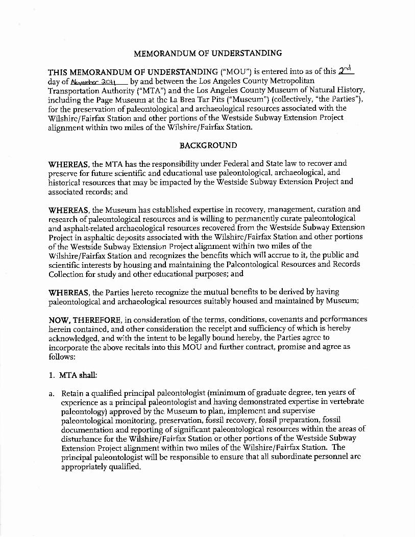
Memorandum of Understanding

THIS PAGE INTENTIONALLY LEFT BLANK


THIS PAGE INTENTIONALLY LEFT BLANK
Appendix G—Memorandum of Understanding for Paleontological Resources
Attachment 1—Paleontological Methods for Mitigation of Fossils in the Vicinity of
Hancock Park

THIS PAGE INTENTIONALLY LEFT BLANK


THIS PAGE INTENTIONALLY LEFT BLANK

Appendix G—Memorandum of Understanding for Paleontological Resources
Attachment 2—Techniques for Excavation, Preparation and Curation of Fossils from the Project 23 Salvage at Rancho La Brea

THIS PAGE INTENTIONALLY LEFT BLANK


Appendix G—Memorandum of Understanding for Paleontological Resources
Attachment 3—Wilshire/Fairfax Station Construction. Paleontological Resources
Extraction

THIS PAGE INTENTIONALLY LEFT BLANK
Wilshire/Fairfax Station Construction. Paleontological Resources Extraction.
December 2011
WESTSIDE SUBWAY EXTENSION PROJECT


Wilshire/Fairfax Station Construction. Paleontological Resources Extraction. Table of Contents
W E S T S I D E S U B W A Y E X T E N S I O N P R O J E C T Page iDecember 2011
Table of Contents 1.0 BACKGROUND ...................................................................................................................... 1 1
2.0 GEOLOGIC CONDITIONS........................................................................................................ 2 1
2.1 Gassy Ground Conditions................................................................................................. 2 2
3.0 EXCAVATION SUPPORT TECHNIQUES.................................................................................... 3 1
3.1 Soldier Piles and Lagging.................................................................................................. 3 3
3.2 Tangent Pile or Secant Pile Walls..................................................................................... 3 5
3.3 Diaphragm/Slurry Walls................................................................................................... 3 5
3.4 Deep Soil Mix Walls ......................................................................................................... 3 7
3.5 Comparison of Excavation Support Techniques ..............................................................3 8
3.6 Construction Staging........................................................................................................ 3 8
3.7 General Approach to Handling Utilities ........................................................................... 3 9
4.0 PALEONTOLOGICAL ISSUES ................................................................................................... 4 1
4.1 Minimize Excavation Done Before Decking Installation ..................................................4 2
4.2 Excavation of the topmost layers beneath the street decking........................................4 3
4.3 Excavate in Layers ............................................................................................................ 4 6
4.4 Fossil Box Size .................................................................................................................. 4 8
4.5 Construction Issues in Tar Laden Soils...........................................................................4 11
4.6 Potential Impacts to Construction Methods from Anticipated Tar Laden Soils............4 11
4.7 Handling Gas Intrusions during Construction Operations .............................................4 12
4.8 Ventilation Schemes ...................................................................................................... 4 13
5.0 CONCLUSIONS AND RECOMMENDATIONS ............................................................................ 5 1

Wilshire/Fairfax Station Construction. Paleontological Resources Extraction. Table of Contents
W E S T S I D E S U B W A Y E X T E N S I O N P R O J E C T Page iiDecember 2011
List of Figures Figure 1 1: Wilshire/Fairfax Station Box .................................................................................................... 1 1Figure 2 1: Core Sample G 118 .................................................................................................................. 2 1Figure 2 2: Core Sample G 123 .................................................................................................................. 2 1Figure 2 3: Core Sample G 124 (1 of 2)...................................................................................................... 2 1Figure 2 4: Core Sample G 124 (2 of 2)...................................................................................................... 2 1Figure 3 1: Open Cut Excavation................................................................................................................ 3 1Figure 3 2: Initial Excavation at Soto Station ............................................................................................. 3 2Figure 3 3: Precast Concrete Decking ........................................................................................................ 3 2Figure 3 4: Installation of Decking (1 of 2)................................................................................................. 3 2Figure 3 5: Installation of Decking (2 of 2)................................................................................................. 3 2Figure 3 6: Roadway Operations Restored on Temporary Decking System..............................................3 3Figure 3 7: Pre augering for Soldier Pile .................................................................................................... 3 4Figure 3 8: Cut and Cover with Soldier Pile and Lagging ........................................................................... 3 4Figure 3 9: Soldier Pile and Lagging ........................................................................................................... 3 4Figure 3 10: Tangent Pile Installation ........................................................................................................ 3 5Figure 3 11: Secant Pile Installation........................................................................................................... 3 5Figure 3 12: Secant Pile Wall at Barnsdall Shaft on Metro Red Line .........................................................3 5Figure 3 13: Steel Reinforcement Cage for Slurry Wall ............................................................................. 3 6Figure 3 14: Slurry Wall Construction Equipment ..................................................................................... 3 6Figure 3 15: Clamshell Digger for Slurry Wall Construction ...................................................................... 3 6Figure 3 16: Deep Soil Mix Construction ................................................................................................... 3 7Figure 3 17: Utilities Hung from Deck Beams ............................................................................................ 3 9Figure 3 18: Utilities Hung from Deck Beams (Close Up) .......................................................................... 3 9Figure 3 19: Backfilling Utilities in Final Location beneath Road Surface................................................3 10Figure 4 1: Tar Deposit Containing Fossils ................................................................................................. 4 1Figure 4 2: Fossil Box Construction at Project 23 ...................................................................................... 4 1Figure 4 3: Smilodon (Sabre Tooth Cat) Pelvic Bone ................................................................................. 4 2Figure 4 4: Smilodon Skull in Fossil Box..................................................................................................... 4 2Figure 4 5: Open Cut Excavation of Side Access Shaft............................................................................... 4 3Figure 4 6: Gradall Excavator East Side Access Project NYC...................................................................4 3Figure 4 7: Cross Section Showing Excavation Procedure of Shallow Lifts at 2:1 (Approx) Slope Beginning
from the Side Access Shaft .............................................................................................. 4 4Figure 4 8: Plan Showing Excavation Procedure of Shallow Lifts with Low Profile Gradall Excavator......4 5Figure 4 9: Compact Track Loader ............................................................................................................. 4 6Figure 4 10: Compact Excavator – 6.75’ Tall/12’ Long/6.5’ Wide ............................................................4 6Figure 4 11: Tracked Loader Removing Muck from Beneath Struts..........................................................4 7Figure 4 12: Hydraulic Excavator between Struts...................................................................................... 4 7
Wilshire/Fairfax Station Construction. Paleontological Resources Extraction. Table of Contents
W E S T S I D E S U B W A Y E X T E N S I O N P R O J E C T Page iiiDecember 2011
Figure 4 13: Track Loader beneath Struts.................................................................................................. 4 7Figure 4 14: Fossil Boxes at Project 23 ...................................................................................................... 4 8Figure 4 15: Fossil Relocation Process. (From Page Museum Whiteboard)..............................................4 9Figure 4 16: Proposed Alternative Boxing Technique Using Auger for Floor Construction ....................4 10Figure 4 17: Aerial View of Project 23 Excavation with Dark Tar Seeps ..................................................4 11Figure 4 18: Fossil Boxes with Worker Donning Oxygen Respirator at Project 23..................................4 12Figure 4 19: Underground Ventilation Ducts........................................................................................... 4 13
List of Tables Table 3 1: Comparison of Excavation Support Types ................................................................................ 3 8
Appendix Appendix A: Example of Raised Decking


December 201
1.0 BThe Wilshbelow streAvenueWilshire aentrancesSouth OgdWilshire Bthe southshafts wilselected fThe statioshoring syshoring syside accestype of sh
W11
BACKGROhire/Fairfax steet level. Thesee Figure 1and Fairfax bes under considden Drive andBoulevard (Mside of Wilsh
l be located afor the stationon box will beystem to suppystem that woss shafts willhoring system
E S T S I D E
OUNDtation box exce station exte1. The statioetween the 99deration; thed; within theay Company)
hire betweenat the construn portal. Thee excavated byport the excaould be integbe excavated
m that is used
Fi
Wilshire/Fai
E S U B W A
cavation willnds beneathn entrance is9 Cent Only Ssouth side oLACMA build). A constructSouth Orang
uction stagingside access sy the cut andvation and derated into the
d by the openon the statio
igure 1-1: Wils
irfax Station Co
Y E X T E N
be approximathe intersectplanned to b
Store and Johf Wilshire beting at the noion staging a
ge Grove Aveng and materiahafts will be ecover metho
ecking systeme permanentcut method an box.
shire/Fairfax S
onstruction. Pa
N S I O N P R
ately 860 ft lotion of Wilshibe located nenie’s Coffee Stween Southrth east cornnd materialsnue and Soutals laydown aexcavated tood and most pm during const station strucand would m
Station Box
aleontological R
R O J E C T
ong, 70 ft widre Boulevardar the northwShop. Two altOrange Grover of Fairfax Alaydown areah Ogden drivrea and at ththe full deptprobably usestruction, thocture could al
most probably
Resources Extra1.0 - Backg
P
de, and 60 toand Fairfax
west corner oternativeve Avenue anAvenue anda is planned f
ve. Side accesse locationh of the statioa temporaryugh a permaso be used. Tuse the same
action.ground
Page 1-1
70 ft
of
d
fors
on.
nentThee

Wilshire/Fairfax Station Construction. Paleontological Resources Extraction. 2.0 - Geologic Conditions
W E S T S I D E S U B W A Y E X T E N S I O N P R O J E C T Page 2-1December 2011
2.0 GEOLOGIC CONDITIONS The geologic conditions in this region consist of soft alluvium deposits of sands, silty sand, clayey sand,gravely sand, silty clay, clayey silt, shell fragments, soil saturated with crude oil, and asphaltic (tar)sands. Several borings were taken within the station area; see Figure 2 1 through Figure 2 4. Core G 118(Figure 2 1) was taken east of the station box between La Brea and Fairfax, the sample at 82 ft belowground surface (bgs) consists of silty clay/clayey silt with traces of crude oil. The portion of ring sampleG 123 shown in Figure 2 2 is located just east of Fairfax at 60 ft bgs and consists of predominantly finegrained soil with channels of medium grained sand saturated with crude oil. Heavy tar was reported inG 123 from 38 – 110 ft bgs. Core sample G 124 (Figure 2 3 and Figure 2 4) was obtained just west ofFairfax by the Standard Penetration Test (SPT). The sample pictured was taken from 80 ft bgs andconsists of medium to coarse grained sand saturated with tar. Heavy tar was reported in G 124 from 45– 105 ft bgs. The consistency of tar in this region ranges from dry and hard to wet and oozing. This reachis also known to contain pockets of pressurized gases and dissolved gases in groundwater. Thegroundwater conditions are measured to have a water table depth of 74 ft bgs, and zones of perchedwater between 10 – 50 ft bgs. Since the station box invert depth will be located between 60 – 70 ft bgs,perched water can be anticipated during excavation.
Figure 2-1: Core Sample G-118 Figure 2-2: Core Sample G-123
Figure 2-3: Core Sample G-124 (1 of 2) Figure 2-4: Core Sample G-124 (2 of 2)
Wilshire/Fairfax Station Construction. Paleontological Resources Extraction. 2.0 - Geologic Conditions
W E S T S I D E S U B W A Y E X T E N S I O N P R O J E C T Page 2-2December 2011
2.1 Gassy Ground ConditionsThe gases present in the soils of this region are methane (CH4) and hydrogen sulfide (H2S). They are likelyto occur in pressurized pockets as well as in a dissolved state in groundwater. These gases can seep intotunnels and other excavations through soil and also through discontinuities (fractures, faults, etc.) inbedrock. CH4 and H2S are considered hazardous gases due to their explosive properties. H2S is also highlytoxic. Being heavier than air, it tends to accumulate at the bottom of poorly ventilated spaces. Althoughvery pungent at first, it quickly deadens the sense of smell, so potential victims may be unaware of itspresence. CH4 is extremely flammable and may form explosive mixtures with air. It is odorless andlighter than air, and it dissipates quickly once at the surface causing no threat of explosion. However, in1985 an explosion occurred at the Ross Dress for Less in the Fairfax area which resulted in injuriesrequiring hospital treatment of twenty three people. The explosion took place in a poorly ventilatedancillary room of the building where CH4 gas had accumulated. There was no gas detection equipment atthis location.

December 201
3.0 ECut and coand coverFigure 3 1decking sy
W11
EXCAVATIover excavatir still leads to1). Traffic inteystem constr
E S T S I D E
ON SUPPion is the prelengthy occu
erruptions canucted at an e
Wilshire/Fai
E S U B W A
PORT TECferred techni
upation of strn be mitigatearly stage (Se
Figure 3-1: O
irfax Station Co
Y E X T E N
CHNIQUESique to excaveets with noid by perform
ee Figure 3 2
Open Cut Exc
onstruction. Pa3
N S I O N P R
Svate the statioise disturbanc
ming most excthrough Figu
cavation
aleontological R3.0 - Excavation
R O J E C T
on box structuces and intercavation belowre 3 6).
Resources Extran Support Techn
P
ure, althoughrupted accessw a temporar
action.niques
Page 3-1
h cuts (seery
Wilshire/Fairfax Station Construction. Paleontological Resources Extraction. 3.0 - Excavation Support Techniques
W E S T S I D E S U B W A Y E X T E N S I O N P R O J E C T Page 3-2December 2011
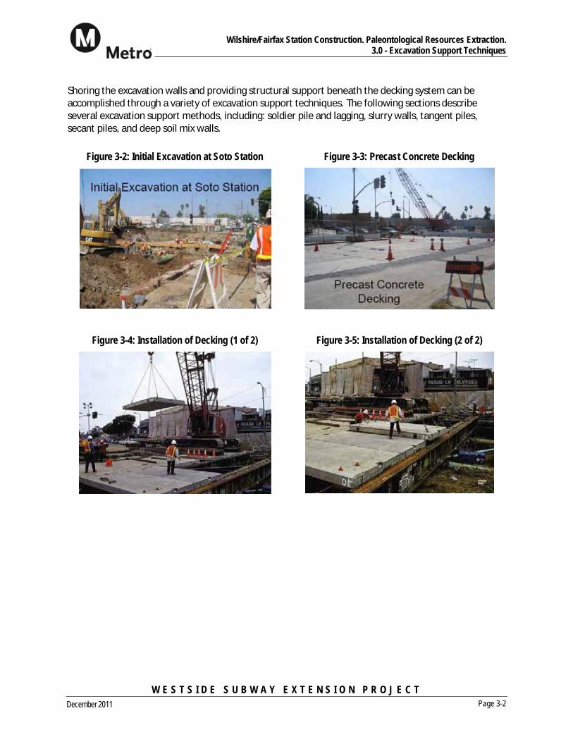
Shoring the excavation walls and providing structural support beneath the decking system can beaccomplished through a variety of excavation support techniques. The following sections describeseveral excavation support methods, including: soldier pile and lagging, slurry walls, tangent piles,secant piles, and deep soil mix walls.
Figure 3-2: Initial Excavation at Soto Station Figure 3-3: Precast Concrete Decking
Figure 3-4: Installation of Decking (1 of 2) Figure 3-5: Installation of Decking (2 of 2)
Wilshire/Fairfax Station Construction. Paleontological Resources Extraction. 3.0 - Excavation Support Techniques
W E S T S I D E S U B W A Y E X T E N S I O N P R O J E C T Page 3-3December 2011
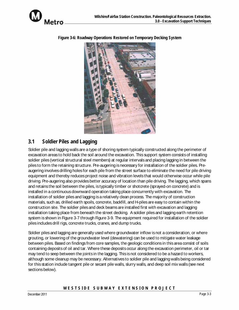
Figure 3-6: Roadway Operations Restored on Temporary Decking System
3.1 Soldier Piles and LaggingSoldier pile and lagging walls are a type of shoring system typically constructed along the perimeter ofexcavation areas to hold back the soil around the excavation. This support system consists of installingsoldier piles (vertical structural steel members) at regular intervals and placing lagging in between thepiles to form the retaining structure. Pre augering is necessary for installation of the soldier piles. Preaugering involves drilling holes for each pile from the street surface to eliminate the need for pile drivingequipment and thereby reduces project noise and vibration levels that would otherwise occur while piledriving. Pre augering also provides better accuracy of location than pile driving. The lagging, which spansand retains the soil between the piles, is typically timber or shotcrete (sprayed on concrete) and isinstalled in a continuous downward operation taking place concurrently with excavation. Theinstallation of soldier piles and lagging is a relatively clean process. The majority of constructionmaterials, such as, drilled earth spoils, concrete, backfill, and H piles are easy to contain within theconstruction site. The soldier piles and deck beams are installed first with excavation and lagginginstallation taking place from beneath the street decking. A soldier piles and lagging earth retentionsystem is shown in Figure 3 7 through Figure 3 9. The equipment required for installation of the soldierpiles includes drill rigs, concrete trucks, cranes, and dump trucks.
Soldier piles and lagging are generally used where groundwater inflow is not a consideration, or wheregrouting, or lowering of the groundwater level (dewatering) can be used to mitigate water leakagebetween piles. Based on findings from core samples, the geologic conditions in this area consist of soilscontaining deposits of oil and tar. Where these deposits occur along the excavation perimeter, oil or tarmay tend to seep between the joints in the lagging. This is not considered to be a hazard to workers,although some cleanup may be necessary. Alternatives to soldier pile and lagging walls being consideredfor this station include tangent pile or secant pile walls, slurry walls, and deep soil mix walls (see nextsections below).

Wilshire/Fairfax Station Construction. Paleontological Resources Extraction. 3.0 - Excavation Support Techniques
W E S T S I D E S U B W A Y E X T E N S I O N P R O J E C T Page 3-4December 2011
Figure 3-7: Pre-augering for Soldier Pile Figure 3-8: Cut and Cover with Soldier Pile and Lagging
Figure 3-9: Soldier Pile and Lagging

Wilshire/Fairfax Station Construction. Paleontological Resources Extraction. 3.0 - Excavation Support Techniques
W E S T S I D E S U B W A Y E X T E N S I O N P R O J E C T Page 3-5December 2011
3.2 Tangent Pile or Secant Pile Walls Tangent pile walls consist of contiguous cast in drilledhole (CIDH) reinforced concrete piles – see Figure 3 10.The contiguous wall generally provides a bettergroundwater seal than the soldier pile and laggingsystem, but some grouting or dewatering could still beneeded to control leakage between piles.
A secant pile wall system is similar to the tangent pile wallbut the piles have some overlap, facilitating better watertightness and rigidity see Figure 3 11. This methodconsists of boring and concreting the primary piles atcenters slightly less than twice the pile diameter.Secondary piles are then bored in between the primarypiles, prior to the concrete achieving much of its strength.
In terms of relative cleanliness, tangent pile andsecant pile walls are comparable to one anotherand both are more difficult to contain than soldierpiles and lagging due to the greater amount ofpumped concrete and the expected largerdiameter of drilled holes. The completed secantpile wall for the Barnsdall Shaft in Hollywood forthe Metro Red Line project is shown on Figure3 12. Secant and Tangent pile shoring systems are slower to construct that soldier pile and lagging andtherefore have the disadvantage of requiring longer lane closures on Wilshire while they are beingconstructed. Furthermore, because of the close spacing of tangentpiles, utilities crossing the wall often require relocation whereas asoldier pile system can often be built around the existing utilities.The equipment required for installation of the tangent pile or secantpile walls includes drill rigs, concrete trucks, cranes, and dumptrucks.
3.3 Diaphragm/Slurry Walls Diaphragm walls (commonly known as slurry walls) are structuralelements used for retention systems and permanent foundationwalls. Use of slurry wall construction can provide a nearly watertightexcavation, eliminating the need to dewater. Slurry walls areconstructed using deep trenches or panels which are kept open byfilling them with a thick bentonite slurry mixture. After the slurryfilled trench is excavated to the required depth, structural elements(typically a steel reinforcement cage see Figure 3 13) are loweredinto the trench and concrete is pumped from the bottom of thetrench, displacing the slurry. Figure 3 14 and Figure 3 15 illustrateslurry wall excavation equipment.
Figure 3-10: Tangent Pile Installation
Figure 3-11: Secant Pile Installation
Figure 3-12: Secant Pile Wall at Barnsdall Shaft on Metro Red
Line

Wilshire/Fairfax Station Construction. Paleontological Resources Extraction. 3.0 - Excavation Support Techniques
W E S T S I D E S U B W A Y E X T E N S I O N P R O J E C T Page 3-6December 2011
Tremie concrete is placed in one continuous operation throughone or more pipes that extend to the bottom of the trench. Theconcrete placement pipes are extracted as the concrete fills thetrench. Once all the concrete is placed and cured, the result is astructural concrete panel. Grout pipes can be placed withinslurry wall panels to be used later in the event that leakagethrough wall sections, particularly at panel joints, is observed.The slurry that is displaced by the concrete is saved and reusedfor subsequent panel excavations.
Slurry wall construction advances in discontinuous sectionssuch that no two adjacent panels are constructedsimultaneously. Stop end steel members are placed vertically ateach end of the primary panel to form joints and guides foradjacent secondary panels. In some cases, these members arewithdrawn as the concrete sets. Secondary panels areconstructed between the primary panels to create a continuous wall. Panels are usually to full depth and8 – 20 ft long and vary from 2 – 5 ft wide.
Similar to other shoring systems, slurry wall construction would occur in stages, working on one side ofthe street at a time. These walls have been constructed in virtually all soil types to provide a watertightsupport system in addition to greater wall stiffness to control ground movement. Because slurry wallsare thicker and more rigid than many other shoring methods, the walls may in some cases be used asthe permanent structural wall, although this application is not anticipated for this project. Where slurrywalls are used, the thickness of the permanent structural walls can sometimes be reduced, i.e. whencompared to wall thicknesses used with a conventional soldier pile and lagging system after removal ofinternal bracing.
Figure 3-13: Steel Reinforcement Cage for Slurry Wall
Figure 3-14: Slurry Wall Construction Equipment Figure 3-15: Clamshell Digger for Slurry Wall
Construction
Wilshire/Fairfax Station Construction. Paleontological Resources Extraction. 3.0 - Excavation Support Techniques
W E S T S I D E S U B W A Y E X T E N S I O N P R O J E C T Page 3-7December 2011
Slurry wall construction materials are the most difficult to contain within the construction site of all theshoring types being considered due to the inherent messy nature of bentonite slurry combined with theoperational characteristics of the clamshell digger which will likely be used to excavate large volumes ofsoil from the wall trench. Slurry walls are generally not adaptable to utility crossings and all utilitiescrossed by the wall would require temporary or permanent relocation. The equipment required forinstallation of the slurry walls includes clamshell or rotary head excavators, concrete trucks, slurrymixing equipment, cranes, slurry treatment plant, and dump trucks. The bentonite slurry would requiredisposal after a number of re use cycles. Slurry walls are also slow to construct and will be verydisruptive to traffic on Wilshire Boulevard.
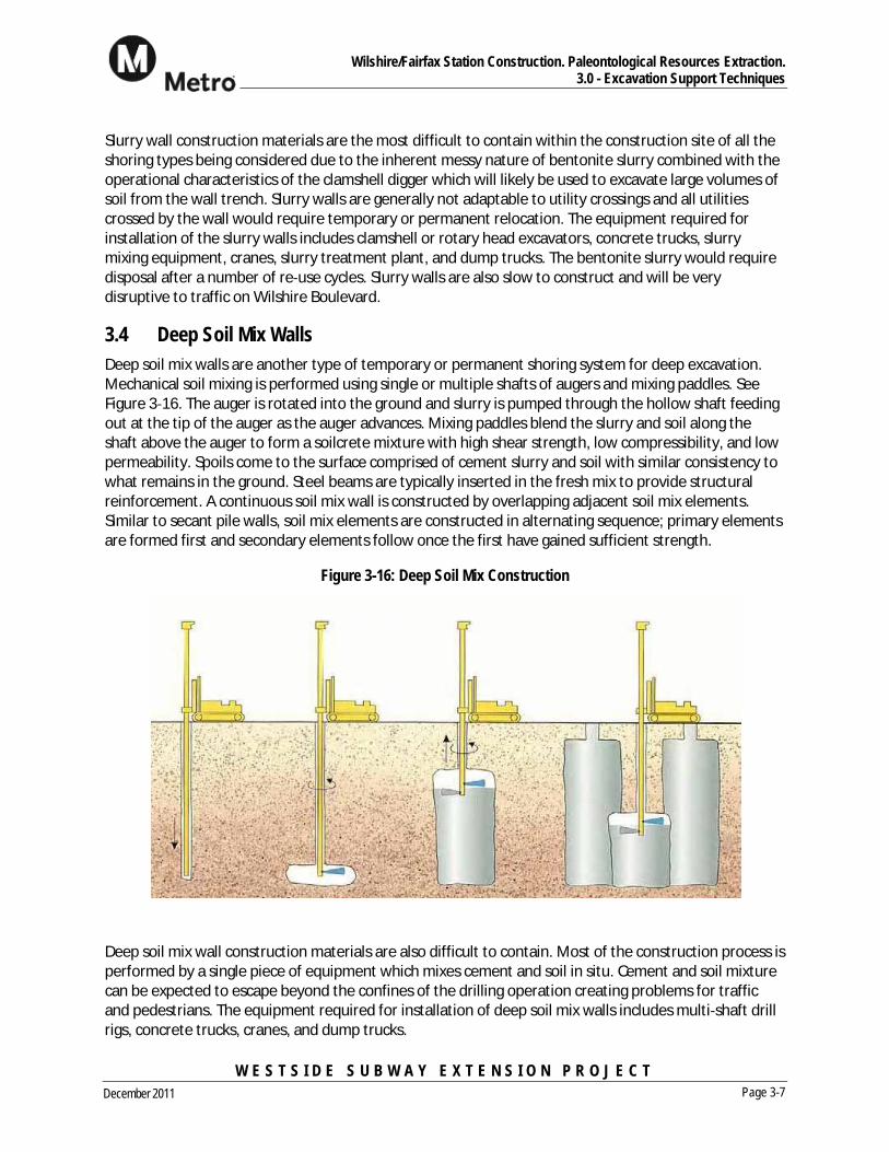
3.4 Deep Soil Mix Walls Deep soil mix walls are another type of temporary or permanent shoring system for deep excavation.Mechanical soil mixing is performed using single or multiple shafts of augers and mixing paddles. SeeFigure 3 16. The auger is rotated into the ground and slurry is pumped through the hollow shaft feedingout at the tip of the auger as the auger advances. Mixing paddles blend the slurry and soil along theshaft above the auger to form a soilcrete mixture with high shear strength, low compressibility, and lowpermeability. Spoils come to the surface comprised of cement slurry and soil with similar consistency towhat remains in the ground. Steel beams are typically inserted in the fresh mix to provide structuralreinforcement. A continuous soil mix wall is constructed by overlapping adjacent soil mix elements.Similar to secant pile walls, soil mix elements are constructed in alternating sequence; primary elementsare formed first and secondary elements follow once the first have gained sufficient strength.
Figure 3-16: Deep Soil Mix Construction
Deep soil mix wall construction materials are also difficult to contain. Most of the construction process isperformed by a single piece of equipment which mixes cement and soil in situ. Cement and soil mixturecan be expected to escape beyond the confines of the drilling operation creating problems for trafficand pedestrians. The equipment required for installation of deep soil mix walls includes multi shaft drillrigs, concrete trucks, cranes, and dump trucks.

Wilshire/Fairfax Station Construction. Paleontological Resources Extraction. 3.0 - Excavation Support Techniques
W E S T S I D E S U B W A Y E X T E N S I O N P R O J E C T Page 3-8December 2011
3.5 Comparison of Excavation Support Techniques Due to the speed of construction, and the ability to work around utilities, soldier piles and lagging ispreferred unless site conditions dictate the use of other methods. See Table 3 1 for a comparison ofexcavation support methods. Soldier piles and lagging is the predominant shoring system used in the LosAngeles area and has been used successfully by Metro on construction of both Red and Gold Linestations. Experience at the LACMA parking garage excavation suggests that soil off gasses immediatelyafter being exposed but with a short period of time, the off gassing slows to levels acceptable for work.This suggest that the relatively impervious seal achieved by slurry walls, secant piles, and deep soil mixwalls may only provide very short term benefits and that gas entering the station box excavationthrough a soldier pile and lagging system could be controlled with a well designed ventilation system.
Since it is anticipated that gassy soils will be encountered regardless of shoring system type, variousmethods of providing a safe and hazard free workplace will be implemented in all situations. No matterwhich type of temporary shoring system is selected; other measures such as, partially open decking,ventilation, gas detection, and Personal Protective Equipment (PPE), will be in use to protect workersfrom gases that may enter the excavation site.
Table 3-1: Comparison of Excavation Support Types
Shoring Method Permeability Installation
DurationContainment
Impacts
Noise / VibrationImpacts
TrafficImpacts
UtilityImpacts
BusinessImpacts
Soldier Pile & Lagging
High concurrent w. excavation
Low Moderate Moderate Moderate Moderate
Slurry Wall Low 3 Months High Moderate High High High
Secant Pile Low 3 Months Moderate Moderate High High High
Tangent Pile Moderate 3 Months Moderate Moderate High High High
Deep Soil Mix Low 3 Months Moderate Moderate High High High
3.6 Construction StagingFor all types of shoring, the contractor would first occupy one side of the street to install one line ofexcavation support piles or wall panels. The installation will require extended closures of 2 – 3 trafficlanes on the side of the street where the equipment would be staged. After installation of piles or wallson both sides of the street at the station excavations, piles or walls would then be installed across thestreet at the station ends. This operation would also require lane closures, and is often done duringnight time or weekend periods. The contractor would then proceed with installation of deck beams,installation of the deck panels and excavation and bracing. Deck panels (decking) allow continued trafficand pedestrian circulation since they will typically be installed flush with the existing street or sidewalklevels though raised decking, which requires less excavation during installation is being discussed withthe traffic authority. Raised decking does have particular advantages at Wilshire / Fairfax Station as lessexcavation during the weekend closures while installing the decking makes it less likely that fossils willbe encountered during the decking operation.

Wilshire/Fairfax Station Construction. Paleontological Resources Extraction. 3.0 - Excavation Support Techniques
W E S T S I D E S U B W A Y E X T E N S I O N P R O J E C T Page 3-9December 2011
Deck installation will require successive full road closures on weekends with traffic detours. The deckingwould be installed in stages, commensurate with the amount of decking that can be installed during aweekend closure. Typical decking installation rates range from 50 100 ft / weekend for an installationcrew. Multiple crews will be used wherever possible to reduce the number of full road closures
3.7 General Approach to Handling Utilities Prior to beginning construction of shoring and decking, it will be necessary to relocate, modify or protectin place all utilities and underground structures that would conflict with excavations. The contractor willverify locations through potholing methods and where feasible, the utility will be relocated so as to stayout of station or other surface structure excavation. Where the utility cannot be relocated outside theexcavation footprint, it will be exposed and hung from the supporting structure (deck beams) for theroadway decking over the cut and cover structure. See Figure 3 17 and Figure 3 18.
Figure 3-17: Utilities Hung from Deck Beams Figure 3-18: Utilities Hung from Deck Beams(Close Up)
Shallow utilities, such as maintenance holes or pull boxes, which would interfere with excavation work,will require relocation. The utilities alignments will be modified and moved away from the proposedfacilities. Utility relocation takes place ahead of station and other underground structure excavation.During this time, it will be necessary to close traffic lanes.
It is possible that in some instances, block long sections of streets would be closed temporarily for utilityrelocation and related construction operations. Pedestrian access (sidewalks) would remain open andvehicular traffic would be re routed. Temporary night sidewalk closures may be necessary in somelocations for the delivery of oversized materials. Special facilities, such as handrails, fences, andwalkways will be provided for the safety of pedestrians.

Wilshire/Fairfax Station Construction. Paleontological Resources Extraction. 3.0 - Excavation Support Techniques
W E S T S I D E S U B W A Y E X T E N S I O N P R O J E C T Page 3-10December 2011
Minor cross streets and alleyways may also be temporarily closed but access to adjacent properties willbe maintained. Major cross streets would require partial closure, half of the street at a time, whilerelocating utilities.
Utilities, such as high pressure water mains andgas lines, which could represent a potential hazardduring cut and cover and open cut stationconstruction and that are not to be permanentlyrelocated away from the work site, would beremoved from the cut and cover or open cut areatemporarily to prevent accidental damage to theutilities, to construction personnel and to theadjoining community. These utilities would berelocated temporarily by the contractor at theearly stages of the operations and reset inessentially their original locations during the finalbackfilling above the constructed station. SeeFigure 3 19
Figure 3-19: Backfilling Utilities in Final Location beneath Road Surface

Wilshire/Fairfax Station Construction. Paleontological Resources Extraction. 4.0 - Paleontological Issues
W E S T S I D E S U B W A Y E X T E N S I O N P R O J E C T Page 4-1December 2011
4.0 PALEONTOLOGICAL ISSUES The Wilshire/Fairfax Station is situated within the vicinity of the Hancock Park Rancho La Brea Tar Pits.The San Pedro Sand layer exists beneath the older and younger alluvium deposits near the surface inthis region. This formation has a high likelihood for producing significant paleontological resources. Theexisting La Brea Tar Pits immediately adjoining the Wilshire/Fairfax Station site is the largest collectionof fossils of extinct mammals in the entire world. Because of the high likelihood of fossil discovery whileexcavating the Wilshire/Fairfax station box, station construction at Wilshire/Fairfax will be given themaximum time available within the overall project schedule, so that excavation can proceed slowly andcarefully and fossils located and removed without schedule pressures.
Before fossil recovery can begin, utility relocation and shoring for the station excavation using one ormore of the shoring methods outlined above must occur. Utility relocations, by their nature (narrowtrenches beneath paved streets) will make recovery of fossils during this phase of the work unlikely.Then, any fossils that lie within the footprint of the shoring will necessarily be destroyed when theshoring is constructed, as there is no way to remove them in advance of the shoring. However, shoringwill at worst occupy less than 10% of the footprint of the station excavation, leaving 90% of the footprintunaffected and suitable for fossil recovery.
The plan for fossil removal has been based on themethods used by the Page Museum for the removal offossils from the nearby LACMA parking garageexcavation, referred to from here on by the PageMuseum name, Project 23. The ground will be excavatedin shallow lifts, with museum staff on land to inspect theexcavated surfaces as earth is removed and to mark thelocations of fossils when discovered. It is assumed thatthe fossils will occur in a manner similar to that at Project23, i.e. concentrated in vertical tar “pipes” which, oncelocated, can be boxed in place and then removed fromthe site for further analysis. As with Project 23, fossils can
also be found away from the tar pipes so all excavatedsurfaces must be inspected, and the contractor’s teammust be alerted to the possibility of finding fossilsanywhere with the excavation. The Project 23 site wasan open excavation, not constrained by a deck atground level. This made boxing and removal of thefossil boxes a good deal more straight forward than willbe the case at Wilshire/Fairfax. Figure 4 1 shows fossilsin a pit at the Page Museum, and Figure 4 2 a boxed“pipe” containing fossils being prepared at the Project23 site. Figure 4 3 and Figure 4 4 show examples offossils recovered from Project 23 after processing.
Figure 4-1: Tar Deposit Containing Fossils
Figure 4-2: Fossil Box Construction at Project 23

Wilshire/Fairfax Station Construction. Paleontological Resources Extraction. 4.0 - Paleontological Issues
W E S T S I D E S U B W A Y E X T E N S I O N P R O J E C T Page 4-2December 2011
Figure 4-3: Smilodon (Sabre Tooth Cat) Pelvic Bone Figure 4-4: Smilodon Skull in Fossil Box
4.1 Minimize Excavation Done Before Decking Installation Although the Project 23 experience suggests that fossils will mainly be 10 ft or more below street level,fossils must be anticipated anywhere within undisturbed ground. Using the cut and cover excavationtechnique, deck beams which support the deck panels are installed in the road bed after the piles orshoring walls are complete. The top of the deck beams sit just below the roadway surface so that thedecking is flush with the roadway. The deck beams are approximately 6 ft tall and joined together withcross bracing so a minimum of 7 ft of excavation is required for their installation. On Red line and GoldLine stations, contractors have normally excavated 10 ft deep when installing the deck beams to provideclear space beneath the beams for better access when commencing to dig out from beneath the deckingand to expose utilities immediately below the deck beams.
Because the street decking requires a full street closure to install, only limited times are available inwhich to close the street. Full street closures, especially along Wilshire Boulevard will be limited toapproximately 52 hours duration on week ends, and this will not provide time to carefully remove soil inlayers to expose fossils nor to box and remove any fossils found in this initial excavation. Therefore,opportunities for fossil recovery from the initial excavation for the street decking will be limited. Ittherefore requires a construction approach to try and reduce the depth of the initial excavation. Twostrategies are being pursued in this regard. One approach is to use raised decking so that the bottoms ofthe deck beams can be raised up by the same height that the station decking is installed above streetlevel. Metro is in discussions with traffic authorities regarding the acceptability of using raised decking atFairfax. See Appendix A for details of raised decking. The other approach is to use shallower deck beams,either for a flush deck system or in conjunction with a raised decking approach. Shallower beams willalmost certainly require installing the deck beams at closer centers, probably 7 ft centers instead of theusual 14 ft centers but the shallow beams will reduce the likelihood of finding fossils during decking.
It should be noted that many utilities in the street are much deeper than the bottom of the deck beams,and any fossils would have been destroyed during the construction of such utilities. Utilities alreadyhave disturbed a significant percentage of the station excavation footprint, and this will increase withthe relocations required prior to the installation of the shoring and decking. Nevertheless, there willremain areas of undisturbed soil within the 10 ft immediately below street level and fossils therefore
Wilshire/Fairfax Station Construction. Paleontological Resources Extraction. 4.0 - Paleontological Issues
W E S T S I D E S U B W A Y E X T E N S I O N P R O J E C T Page 4-3December 2011
could be found in these locations. These areas can be mapped in advance so that they can be excavatedcarefully.
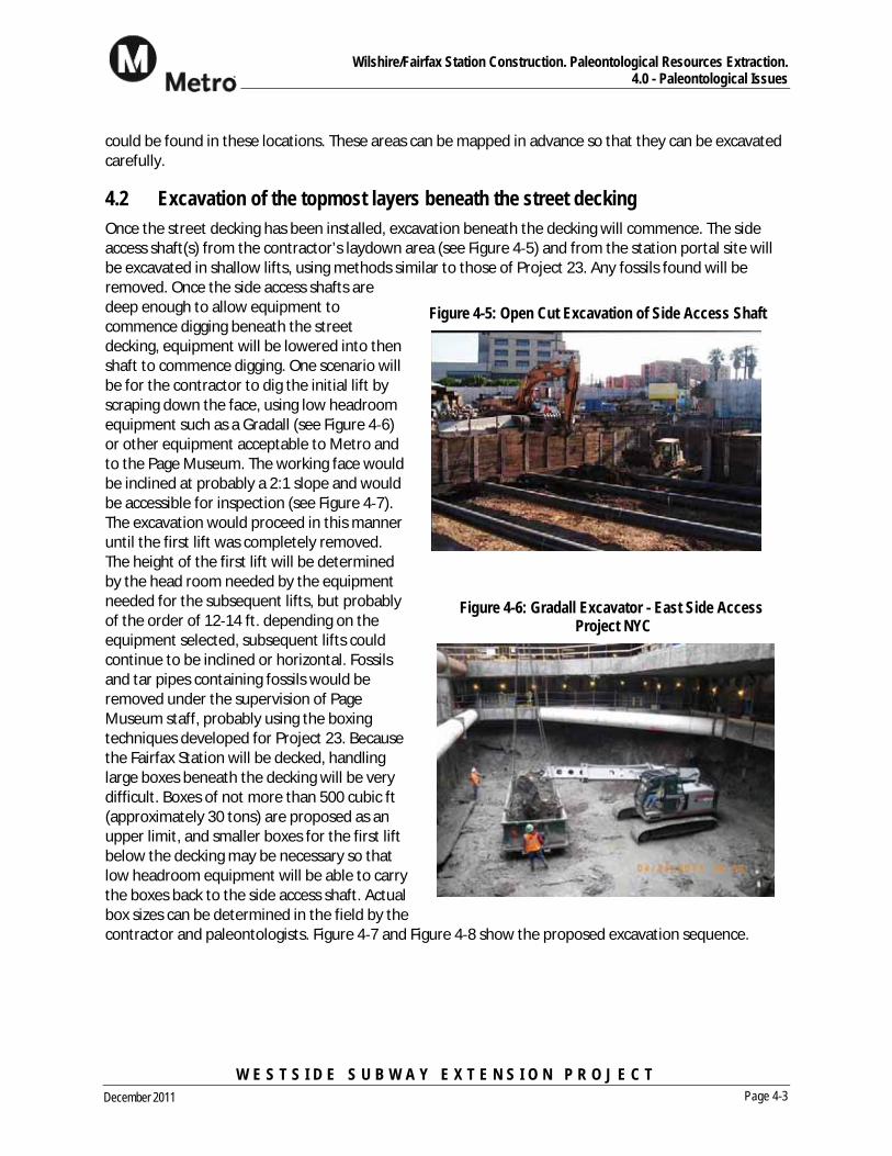
4.2 Excavation of the topmost layers beneath the street decking Once the street decking has been installed, excavation beneath the decking will commence. The sideaccess shaft(s) from the contractor’s laydown area (see Figure 4 5) and from the station portal site willbe excavated in shallow lifts, using methods similar to those of Project 23. Any fossils found will beremoved. Once the side access shafts aredeep enough to allow equipment tocommence digging beneath the streetdecking, equipment will be lowered into thenshaft to commence digging. One scenario willbe for the contractor to dig the initial lift byscraping down the face, using low headroomequipment such as a Gradall (see Figure 4 6)or other equipment acceptable to Metro andto the Page Museum. The working face wouldbe inclined at probably a 2:1 slope and wouldbe accessible for inspection (see Figure 4 7).The excavation would proceed in this manneruntil the first lift was completely removed.The height of the first lift will be determinedby the head room needed by the equipmentneeded for the subsequent lifts, but probablyof the order of 12 14 ft. depending on theequipment selected, subsequent lifts couldcontinue to be inclined or horizontal. Fossilsand tar pipes containing fossils would beremoved under the supervision of PageMuseum staff, probably using the boxingtechniques developed for Project 23. Becausethe Fairfax Station will be decked, handlinglarge boxes beneath the decking will be verydifficult. Boxes of not more than 500 cubic ft(approximately 30 tons) are proposed as anupper limit, and smaller boxes for the first liftbelow the decking may be necessary so thatlow headroom equipment will be able to carrythe boxes back to the side access shaft. Actualbox sizes can be determined in the field by thecontractor and paleontologists. Figure 4 7 and Figure 4 8 show the proposed excavation sequence.
Figure 4-5: Open Cut Excavation of Side Access Shaft
Figure 4-6: Gradall Excavator - East Side Access Project NYC

Wilshire/Fairfax Station Construction. Paleontological Resources Extraction. 4.0 - Paleontological Issues
W E S T S I D E S U B W A Y E X T E N S I O N P R O J E C T Page 4-4December 2011
Figure 4-7: Cross Section Showing Excavation Procedure of Shallow Lifts at 2:1 (Approx) Slope Beginning from the Side Access Shaft

Wilshire/Fairfax Station Construction. Paleontological Resources Extraction. 4.0 - Paleontological Issues
W E S T S I D E S U B W A Y E X T E N S I O N P R O J E C T Page 4-5December 2011
Figure 4-8: Plan Showing Excavation Procedure of Shallow Lifts with Low-Profile Gradall Excavator
Wilshire/Fairfax Station Construction. Paleontological Resources Extraction. 4.0 - Paleontological Issues
W E S T S I D E S U B W A Y E X T E N S I O N P R O J E C T Page 4-6December 2011
4.3 Excavate in LayersThe station box and side access shafts will be excavated in shallow lifts to carefully expose and locatefossils. The Page Museum is suggesting 6” lifts based on experience at the Los Angeles County Museumof Art (LACMA) parking garage. As with Project 23, fossils can also be found away from the tar pipes soall excavated surfaces must be inspected, and the contractor’s team must be alerted to the possibilityof finding fossils anywhere with the excavation.
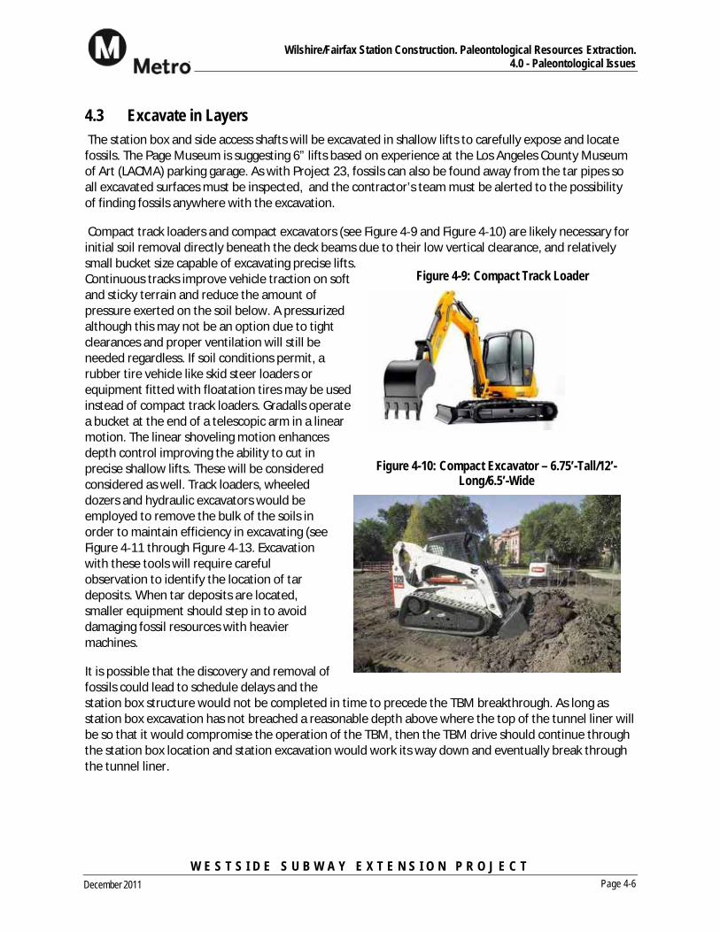
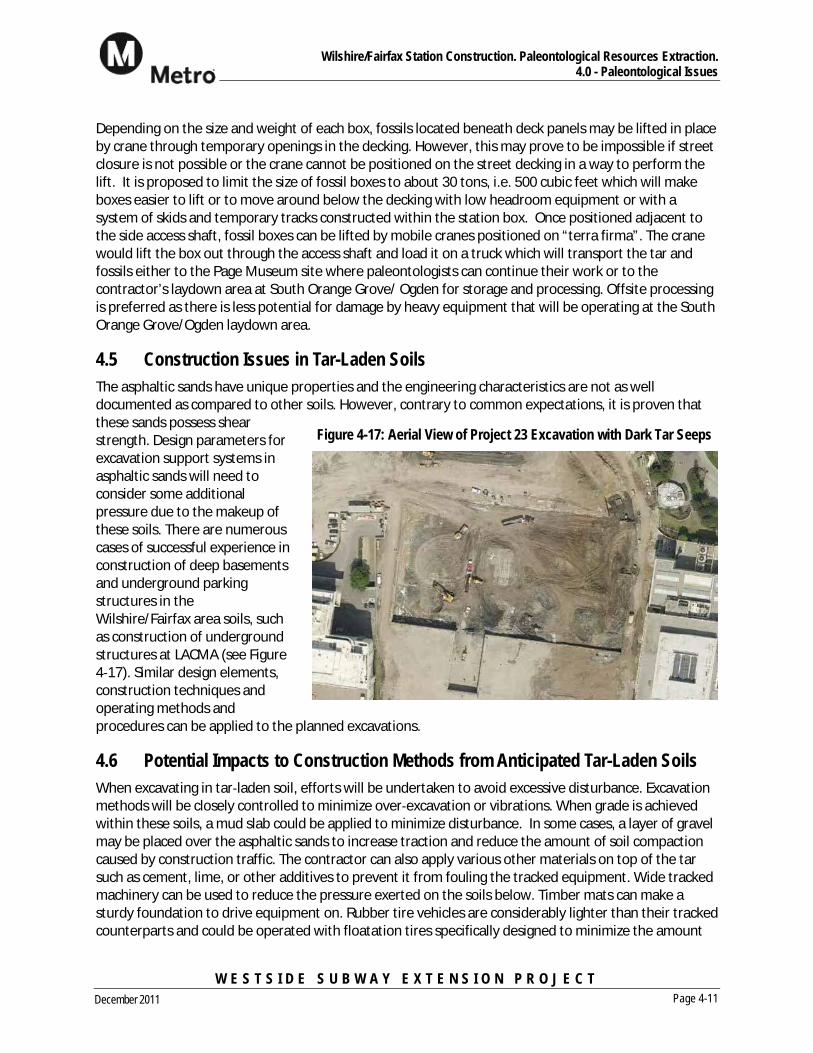
Compact track loaders and compact excavators (see Figure 4 9 and Figure 4 10) are likely necessary forinitial soil removal directly beneath the deck beams due to their low vertical clearance, and relativelysmall bucket size capable of excavating precise lifts.Continuous tracks improve vehicle traction on softand sticky terrain and reduce the amount ofpressure exerted on the soil below. A pressurizedalthough this may not be an option due to tightclearances and proper ventilation will still beneeded regardless. If soil conditions permit, arubber tire vehicle like skid steer loaders orequipment fitted with floatation tires may be usedinstead of compact track loaders. Gradalls operatea bucket at the end of a telescopic arm in a linearmotion. The linear shoveling motion enhancesdepth control improving the ability to cut inprecise shallow lifts. These will be consideredconsidered as well. Track loaders, wheeleddozers and hydraulic excavators would beemployed to remove the bulk of the soils inorder to maintain efficiency in excavating (seeFigure 4 11 through Figure 4 13. Excavationwith these tools will require carefulobservation to identify the location of tardeposits. When tar deposits are located,smaller equipment should step in to avoiddamaging fossil resources with heaviermachines.
It is possible that the discovery and removal offossils could lead to schedule delays and thestation box structure would not be completed in time to precede the TBM breakthrough. As long asstation box excavation has not breached a reasonable depth above where the top of the tunnel liner willbe so that it would compromise the operation of the TBM, then the TBM drive should continue throughthe station box location and station excavation would work its way down and eventually break throughthe tunnel liner.
Figure 4-9: Compact Track Loader
Figure 4-10: Compact Excavator – 6.75’-Tall/12’-Long/6.5’-Wide

Wilshire/Fairfax Station Construction. Paleontological Resources Extraction. 4.0 - Paleontological Issues
W E S T S I D E S U B W A Y E X T E N S I O N P R O J E C T Page 4-7December 2011
Figure 4-13: Track Loader beneath Struts
It may be possible to use an imaging technique to locate fossils ahead of excavating operations thusallowing the pace of excavation to accelerate beyond the recommended 6” lift limit. If the imagingtechnique produces a reliable indication, the boxing of fossils can be pre planned. Some techniques ofscanning for objects below the surface that should be considered are Ground Penetrating Radar (GPR),HAARP Detection using ELF and VLF radio waves, electrical resistivity imaging, and geophysicaldiffraction tomography.
If an Early Work Authorization is obtained, construction can begin on an exploratory shaft to test theeffectiveness of the anticipated geophysical methods. The shaft could be located within the limits of aside access shaft and would ideally reach full station depth in order to learn as much as possible fromthis process. The length and width of the shaft should be a minimum size to allow a variety of theequipment under consideration to perform excavation operations during the exploration process.Construction methods will be tested to determine the best techniques and tools for station boxexcavation. Shoring types will be tested to determine the effectiveness of the planned shoring in thesoils present in the area. Gas levels will be measured to gauge the specifics of the ventilation scheme.
Figure 4-11: Tracked Loader Removing Muck from Beneath Struts Figure 4-12: Hydraulic Excavator between Struts

Wilshire/Fairfax Station Construction. Paleontological Resources Extraction. 4.0 - Paleontological Issues
W E S T S I D E S U B W A Y E X T E N S I O N P R O J E C T Page 4-8December 2011
4.4 Fossil Box Size As layers of soil are removed, tar laden sand deposits containing fossils are likely to be uncovered. Whenthis happens, work is halted within proximity of the fossil to allow the paleontologists on site to assessthe discovery and begin preparations for boxing and removal of the deposit. The technique of boxingand removing fossil deposits to an off site facility for additional paleontological work is an efficientprocess that was first implemented at the La Brea Tar Pits in 1915 and more recently during theconstruction of Project 23. A photo of the 1915 boxing method is contained on Page 8 of Rancho LaBrea, Death Trap and Treasure Trove, Edited by John M. Harris, June 2001.
The box construction technique used onProject 23 is similar to that which is used forboxing palm trees for transport. See Figure4 14. First, the paleontologist defines thelocation of the fossil deposit. Next, trenchesare dug around the sides and excavationcontinues by removing sterile soil fromaround the fossil zone with heavy equipmentleaving an island where the deposit sits. Thebottom of the box is most challenging. Afterthe box is supported by blocks and shims ateach of the four corners, workers must crawlbeneath the box and dig by hand whileinserting the timber boards which make upthe base of the box (Figure 4 15). An alternative approach to creating the bottom of the box whichwould improve worker safety and expedite the excavation process would require an auger to drill holesin the island beneath the fossil deposit. Timbers would be inserted through the auger holes, thusbeginning to form the base of the box. The auger would then remove the balance of soil between thetimbers allowing completion of the box and freeing the deposit from the soil below. See Figure 4 16.During the excavation of Project 23, sixteen tar deposits were discovered. From the sixteen deposits,twenty three boxes were recovered, thus giving the parking garage project its name. The boxes range insize from 5x5x5 ft (weighing 3 tons) to 12x15x10 ft (weighing 56 tons).
Figure 4-14: Fossil Boxes at Project 23

Wilshire/Fairfax Station Construction. Paleontological Resources Extraction. 4.0 - Paleontological Issues
W E S T S I D E S U B W A Y E X T E N S I O N P R O J E C T Page 4-9December 2011
Figure 4-15: Fossil Relocation Process. (From Page Museum Whiteboard)

Wilshire/Fairfax Station Construction. Paleontological Resources Extraction. 4.0 - Paleontological Issues
W E S T S I D E S U B W A Y E X T E N S I O N P R O J E C T Page 4-10December 2011
Figure 4-16: Proposed Alternative Boxing Technique Using Auger for Floor Construction
Wilshire/Fairfax Station Construction. Paleontological Resources Extraction. 4.0 - Paleontological Issues
W E S T S I D E S U B W A Y E X T E N S I O N P R O J E C T Page 4-11December 2011
Depending on the size and weight of each box, fossils located beneath deck panels may be lifted in placeby crane through temporary openings in the decking. However, this may prove to be impossible if streetclosure is not possible or the crane cannot be positioned on the street decking in a way to perform thelift. It is proposed to limit the size of fossil boxes to about 30 tons, i.e. 500 cubic feet which will makeboxes easier to lift or to move around below the decking with low headroom equipment or with asystem of skids and temporary tracks constructed within the station box. Once positioned adjacent tothe side access shaft, fossil boxes can be lifted by mobile cranes positioned on “terra firma”. The cranewould lift the box out through the access shaft and load it on a truck which will transport the tar andfossils either to the Page Museum site where paleontologists can continue their work or to thecontractor’s laydown area at South Orange Grove/ Ogden for storage and processing. Offsite processingis preferred as there is less potential for damage by heavy equipment that will be operating at the SouthOrange Grove/Ogden laydown area.
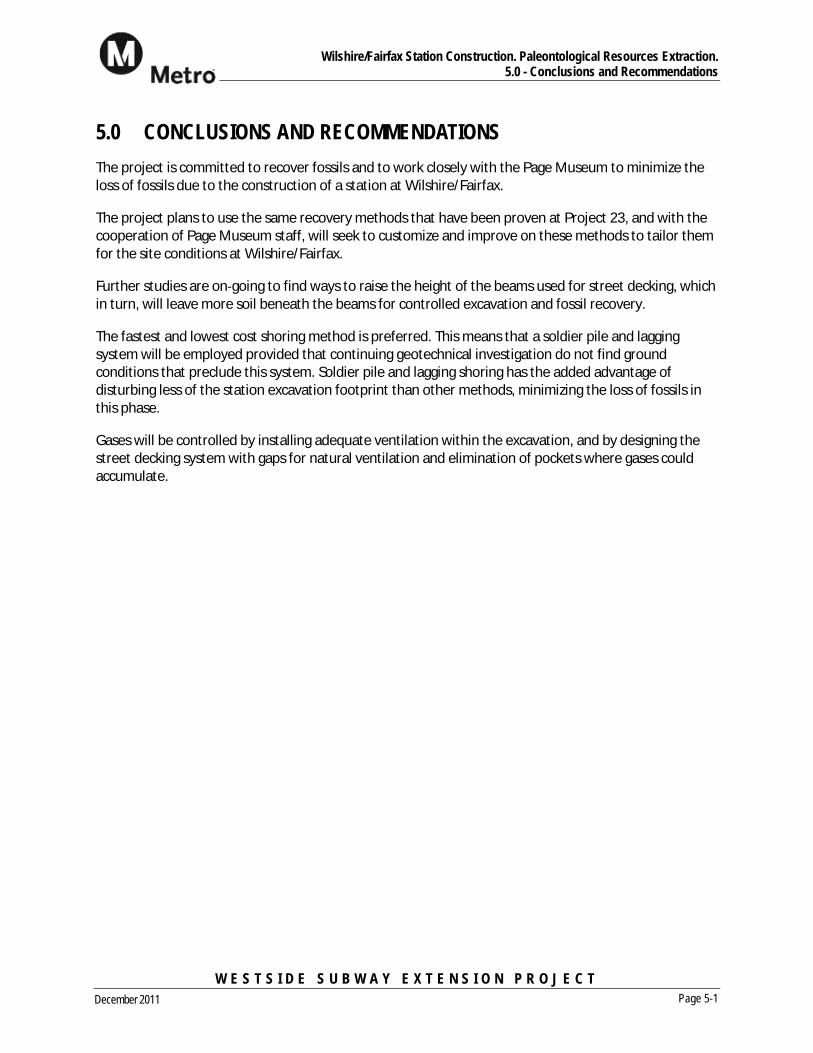
4.5 Construction Issues in Tar-Laden Soils The asphaltic sands have unique properties and the engineering characteristics are not as welldocumented as compared to other soils. However, contrary to common expectations, it is proven thatthese sands possess shearstrength. Design parameters forexcavation support systems inasphaltic sands will need toconsider some additionalpressure due to the makeup ofthese soils. There are numerouscases of successful experience inconstruction of deep basementsand underground parkingstructures in theWilshire/Fairfax area soils, suchas construction of undergroundstructures at LACMA (see Figure4 17). Similar design elements,construction techniques andoperating methods andprocedures can be applied to the planned excavations.
4.6 Potential Impacts to Construction Methods from Anticipated Tar-Laden Soils When excavating in tar laden soil, efforts will be undertaken to avoid excessive disturbance. Excavationmethods will be closely controlled to minimize over excavation or vibrations. When grade is achievedwithin these soils, a mud slab could be applied to minimize disturbance. In some cases, a layer of gravelmay be placed over the asphaltic sands to increase traction and reduce the amount of soil compactioncaused by construction traffic. The contractor can also apply various other materials on top of the tarsuch as cement, lime, or other additives to prevent it from fouling the tracked equipment. Wide trackedmachinery can be used to reduce the pressure exerted on the soils below. Timber mats can make asturdy foundation to drive equipment on. Rubber tire vehicles are considerably lighter than their trackedcounterparts and could be operated with floatation tires specifically designed to minimize the amount
Figure 4-17: Aerial View of Project 23 Excavation with Dark Tar Seeps

Wilshire/Fairfax Station Construction. Paleontological Resources Extraction. 4.0 - Paleontological Issues
W E S T S I D E S U B W A Y E X T E N S I O N P R O J E C T Page 4-12December 2011
of soil compaction caused by heavy equipment. Because the tar is rather sticky or tacky in some areas, itis anticipated that the equipment’s tracks, axles, or buckets could become fouled and would requireoccasional cleaning. Steam cleaners would handle the task well, by heating the tar to a less viscousconsistency.
4.7 Handling Gas Intrusions during Construction OperationsPrevious projects in the Methane Risk Zone have been successfully and safely excavated. Multipleunderground parking garages have been constructed in this area. For example, LACMA built a two levelsubterranean parking structure in the Methane Risk Zone, previously referred to as Project 23. Duringthe excavation, H2S (above safe working levels) was encountered on several occasions. Workers donnedPPE to protect against exposure during these events (se Figure 4 18). Further investigation of operatingunderground structures will be undertaken during future design phases to assess effectiveness of barriersystems and detection equipment used.
Since the majority of gas is expected to enter theexcavation through the excavation surface, therelease of gases may be constricted by applying aground cover to all areas except the area wherecurrent excavation operations are taking place. Animpervious membrane of Visqueen plastic sheeting orgeotextile fabric may serve this purpose.
In areas of potential H2S exposure, there are anumber of techniques that can be used to lower therisk of H2S release or exposure. Because stationexcavations are less confined than tunnels, gasexposure issues are anticipated to be less significant.Although pre treatment of the ground water prior toexcavation, with additives such as hydrogen peroxideor copper zinc, is an option, it is not expected to berequired. If released, H2S will not naturally dissipatebecause it is heavier than air, hence it would build uparound the bottom of the excavation. The first line ofdefense is dewatering since H2S occurs in a dissolvedstate in ground water. Dewatering will remove anycontaminated water from the excavation area. At thesurface, a sealed tank would capture the water andtreat the air for H2S off gassing before discharging it
to the surrounding environment. Additionally, a ventilation system will be used to introduce fresh air inthe workspace. Fans will be used to circulate the air while a gas detection system monitors levels ofhazardous gas. A suction system fitted with scrubbers may be required to collect H2S from the bottomof the excavation and treat the air before discharging clean air at the street surface.
CH4 is a hazard in confined spaces. As such, it is essential that workers be sufficiently protected, andthus detection and monitoring equipment would be required. Fans similar to those used to dilute H2S
Figure 4-18: Fossil Boxes with Worker Donning Oxygen Respirator at Project 23

Wilshire/Fairfax Station Construction. Paleontological Resources Extraction. 4.0 - Paleontological Issues
W E S T S I D E S U B W A Y E X T E N S I O N P R O J E C T Page 4-13December 2011
concentrations would also dilute CH4 concentrations in the station box. Once above ground, CH4dissipates rapidly in the atmosphere and would not be a health hazard.
4.8 Ventilation Schemes Ventilation is required to combat harmful or dangerous gasses when present in undergroundconstruction. Cal OSHA classifies subterranean work areas as “gassy”, “potentially gassy”, “non gassy”,or “extra hazardous”. Excavation equipment in “gassy” spaces must be manufactured to resistaccidental sparks and either be sealed or of explosion proof design.
Since CH4 and H2S gases are expected to be encountered during the excavation of Wilshire/Fairfaxstation, adequate ventilation and continuous air quality monitoring will be in use throughoutconstruction. In addition to maintaining acceptable levels of CH4 and H2S in the air supply, theventilation system must maintain a certain level airflow for workers present in the work space (seeFigure 4 19) . The size of the system is dependent on the number of persons and the size of dieselequipment underground. The air supply shall not be less than 200 CFM (cubic feet per minute) perperson underground, plus 100 CFM per diesel horse brake power.
Use of perforated deck panels, either perforated steel or concrete integrated with steel could be used inplace of concrete only deck panels to allow the free flow of air between the excavation area and thesurface, especially if full decking is required across the entire station box.
Figure 4-19: Underground Ventilation Ducts
Wilshire/Fairfax Station Construction. Paleontological Resources Extraction. 5.0 - Conclusions and Recommendations
W E S T S I D E S U B W A Y E X T E N S I O N P R O J E C T Page 5-1December 2011
5.0 CONCLUSIONS AND RECOMMENDATIONS The project is committed to recover fossils and to work closely with the Page Museum to minimize theloss of fossils due to the construction of a station at Wilshire/Fairfax.
The project plans to use the same recovery methods that have been proven at Project 23, and with thecooperation of Page Museum staff, will seek to customize and improve on these methods to tailor themfor the site conditions at Wilshire/Fairfax.
Further studies are on going to find ways to raise the height of the beams used for street decking, whichin turn, will leave more soil beneath the beams for controlled excavation and fossil recovery.
The fastest and lowest cost shoring method is preferred. This means that a soldier pile and laggingsystem will be employed provided that continuing geotechnical investigation do not find groundconditions that preclude this system. Soldier pile and lagging shoring has the added advantage ofdisturbing less of the station excavation footprint than other methods, minimizing the loss of fossils inthis phase.
Gases will be controlled by installing adequate ventilation within the excavation, and by designing thestreet decking system with gaps for natural ventilation and elimination of pockets where gases couldaccumulate.

Wilshire/Fairfax Station Construction. Paleontological Resources Extraction.Appendix A - Example of Raised Decking
W E S T S I D E S U B W A Y E X T E N S I O N P R O J E C T December 2011
APPENDIX A EXAMPLE OF RAISED DECKING


Wilshire/Fairfax Station Construction. Paleontological Resources Extraction.Appendix A - Example of Raised Decking
W E S T S I D E S U B W A Y E X T E N S I O N P R O J E C T Page A-1December 2011