westt trenchless review
TRANSCRIPT

2 Western Society of Trenchless Technology - Trenchless Review - 2011
SMaRT is a transparent, multi-attribute, sustainable productstandard and third party certification program. Certificationdepends on a robust analysis of a life cycle assessment andthe associated environmental, economic and social impacts.Unlike some single-attribute certifications, you can’t get aSMaRT Certified based only on recycled content. Thisstandard analyzes impacts from raw materials extraction,manufacturing, transportation, and end-use until disposalor recycling.

3Western Society of Trenchless Technology - Trenchless Review - 2011
Western Society of Trenchless Technology -Trenchless Review
Published by:
Unit 1 – 73 Fontaine Crescent
Winnipeg, Manitoba
Canada R2J 2H7
COMMUNICATIONS
© Copyright 2011 PTR Communications. All rights
reserved. The contents of this publication may not be
reproduced by any means, in whole or in part, with-
out the express written permission of the Publisher. Printed in Canada 09/11
While every effort has been made to
ensure the accuracy of the information con-
tained herein and the reliability of the
sources, the Publisher in no way guaran-
tees or warrants the information herein,
and is not responsible for errors, omis-
sions, or statements made by advertisers.
Opinions or recommendations made by
contributors or advertisers are not neces-
sarily those of PTR Communications, its
officers or employees.
Managing PartnerElaine Chouinard
EditorMike Stimpson204.231.4707
Advertising SalesAndrew Pattison
Layout & DesignLunch Pail Productions
fall 2011
Chairman’s Message ~ Jennifer A Glynn 5
NASTT Chairman’s Message ~ George Ragula 6
WESTT Board of Directors, 2010-2011 7
In Memoriam: Paddy Ryan O’Toole 8
No-Dig 2011 Report 9
No-Dig 2012 Update ~ George Ragula and Kim Staheli 10
L.A. Milestone ~ Mary Thomas, Mina Azarnia, Keith Hanks 13
Large Diameter HDD Project Completes LAVWMA Pipeline 21
Biggest Sewer Line in Utah Gets the Slip! 25
St. Helena, California ~ Collins Orton 27
Guidelines for Mini-HDD ~ Lawrence M. Slavin 31
Managing Geotechnical Risks ~ David C. Mathy 34
Trenchless in Montana ~ Jon Vaccaro 36
Breakthrough Technology ~ Mo Ehsani 39
Leave No Trace: The History of Lateral Pipe Bursting ~ John Rafferty 42
Vitrified Clay Jacking Pipe ~ Jeff Boschert 44
NASTT Calendar of Events 47
Index to Advertisers 51
4 Western Society of Trenchless Technology - Trenchless Review - 2011
Table of Contents
5Western Society of Trenchless Technology - Trenchless Review - 2011
Welcome back to our sixth edition of
the Western Regional Trenchless
Review! As our regional chapter contin-
ues to become established in the indus-
try, we are excited to produce and dis-
tribute valuable information and ideas
centered around a region of the coun-
try that continues to grow and thrive
despite the difficult economy. Thank
you to all the advertisers and article
contributors for helping to make this
year’s magazine a success.
This year, the Seventh Annual
Conference will be held in San Jose,
California, at the Wyndham Hotel on
October 3-4. This year’s focus continues
to be about our goal to become a
“local” source for connecting individu-
als interested in learning about various
trenchless technologies as a viable solu-
tion to their infrastructure needs. San
Jose is a prime location in the Bay Area
of Northern California that is accessible
to dozens of municipalities who con-
tinue to face local challenges regarding
state and federal water and wastewater
regulations, the balance of water supply
Chairman’s Message
Jennifer A. Glynn
I will remain active with the Chapter
and I look forward to another excellent
year with great new leadership for
trenchless activities in the Western
region. I also welcome new members to
join the Western Chapter. Please feel
free to contact me at jglynn@rmcwa-
ter.com or (925) 627-4151 or check out
our website at www.westt.org if you
require any information on WESTT or
trenchless in general.
Warmest regards,
Jennifer A. Glynn, P.E.
Chairman, WESTT
Chairman’s Message
versus demand, and the struggling
economy. Trenchless technology can be
an economical and smart solution. We
must all strive to continue to grow and
learn.
I’m excited that this year’s confer-
ence is in my “neck of the woods,” as I
currently work and live the East Bay of
Northern California. I also find it fit-
ting that this is where I will bid my
farewell to the Chair position of WESTT
and welcome in new leadership with
fresh ideas and wonderful energy. My
time as Chair of WESTT has been very
rewarding, and I have learned a
tremendous amount from others in the
industry that I have been fortunate
enough to work with while represent-
ing WESTT.
Specializing in All Methods ofTrenchless Pipe Installation• Electrical • Irrigation • Traffic Signals
• Street Lights • Fiber • Sewer • Gas • Water & Steel Castings up to 24” Diameter
Call us for your next project to see how trenchless can save money andenhance the image of your company!
• Directional Boring • Pipe Jacking/Raming • Auger Boring • Slip Lining • Pipe Bursting • Pipe Splitting
Ph: 951•453•2382 Fax: 951•789•6654 Email: [email protected]
Union & Non-UnionLic. #838671
WESTT Board of Directors:2010 - 2011
6 Western Society of Trenchless Technology - Trenchless Review - 2011
With less than a month from the 7th
annual Western Regional No-Dig
Conference in San Jose, I cannot help
feeling extremely excited for our volun-
teer members of our Western Chapter
(WESTT). By the time most of you get a
chance to read this, the conference will
be well underway. From the presenta-
tions to the exhibits, attendees can
expect another extraordinary event!
Since 2003, the WESTT Chapter has
been and continues to be the focal
point for advancing the use of trench-
less methods and applications in
Arizona, California, New Mexico,
Nevada, and Hawaii. Indeed, the
WESTT Chapter has always been one of
our Society’s strongest.
The Chapter is fortunate to have
great leadership at the helm from
NASTT members, including Jennifer
Glynn, Chair; Matt Wallin, Treasurer;
Jason Lueke, Secretary; Kate Wallin,
Conference Planning Chair; and
Samuel Ariaratnam, who now serves as
Greetings from NaSTT’s Chairman
ISTT’s Chair, just to name a few. Many
other chapter members are active in
NASTT, serving on the No-Dig Program
Committee, as instructors of our
NASTT Good Practices Courses, and as
student chapter faculty advisors.
Others have served with distinction on
NASTT’s Board of Directors.
Commitment and involvement are
essential ingredients for success. The
WESTT Chapter demonstrates an abun-
dance of these attributes as illustrated
by the breadth of its Chapter activities,
which include conducting a first-class
conference in every respect. As a fur-
ther service to the region, WESTT plans
on hosting a NASTT Good Practices
Course in the spring of 2012.
And there’s more! In 2013, NASTT
will host the annual No-Dig Show in
your Chapter’s backyard – Sacramento,
California. Sacramento was chosen as
the location not simply for the obvious
reasons of its attraction as a cosmopoli-
tan destination, but also because of the
strong support we know we will receive
from NASTT members in the region.
I believe strongly in the role NASTT
regional chapters can and must play in
driving the growth of trenchless tech-
nology at the grassroots level. That’s
why I am pleased to be joining you for
the 7th annual Western Regional No-
Dig Conference and to discuss how we
can work together to accomplish the
very worthy mission of NASTT. See you
in San Jose!
NaSTT Chairman’s Message
George Ragula
WESTT Board of Directors:2010 - 2011
7Western Society of Trenchless Technology - Trenchless Review - 2011
WESTT Board of Directors
Jennifer Glynn, Chairman - RMC Water and Environment
Matthew Wallin, Treasurer – Bennett Trenchless Engineers
Jason Lueke, Secretary - Arizona State University
Samuel Ariaratnam, Advisor –Arizona State University
Craig Camp, Director –Jacobs Associates
Collins Orton, Director –TT Technologies
Cindy Preuss, Director –Harris and Associates
Michael Rocco, Director–AUI Incorporated
Paul Reilly, Director –Rain for Rent
Mike Stram, Director –City of Reno
Read the article on page 39 to learn
about full benefits of StifPipe™.
8 Western Society of Trenchless Technology - Trenchless Review - 2011
NASTT extends our deep-
est sympathies to the fami-
ly and friends of Paddy
Ryan O’Toole, founder and
President of PTR
Communications. After a
courageous battle with
cancer, Paddy passed
away peacefully on
Saturday, July 16, with his
family and trusty dog Tessa close by his side.
Even in his final days, health rapidly declining, Paddy
remained dedicated, bravely striving to bring high-
quality magazines such as the next issue of Western
Regional Trenchless Review to completion. For
Paddy, publishing was more than mere work – it was
his passion and higher purpose. He took great delight
and satisfaction from carefully producing magazines
for many of the NASTT Chapters with the highest
written and artistic quality possible.
Paddy was forever attentive to the interests of the
NASTT community and was a notable proponent and
friend of the trenchless technology industry. He
worked relentlessly at raising the profile and helping
to further the cause of numerous NASTT Chapters.
Very simply, Paddy LOVED trenchless! The maga-
zines were his “love made visible.”
For those who knew him professionally and personal-
ly, Paddy was a great humanitarian with a deep love
for the written word. He was a vastly talented writer,
gifted musician and remarkably astute businessman.
Charming, intelligent and a witty conversationalist,
Paddy was always ready with a practical joke or
funny play on words.
On behalf of NASTT and all the Regional Chapters,
we thank Paddy for his significant contribution to the
trenchless technology industry.
Mike Willmets
Executive Director, NASTT
IN MEMORIaM: PADDY RYAN O’TOOLE JUNE 29, 1958 – JUlY 16, 2011
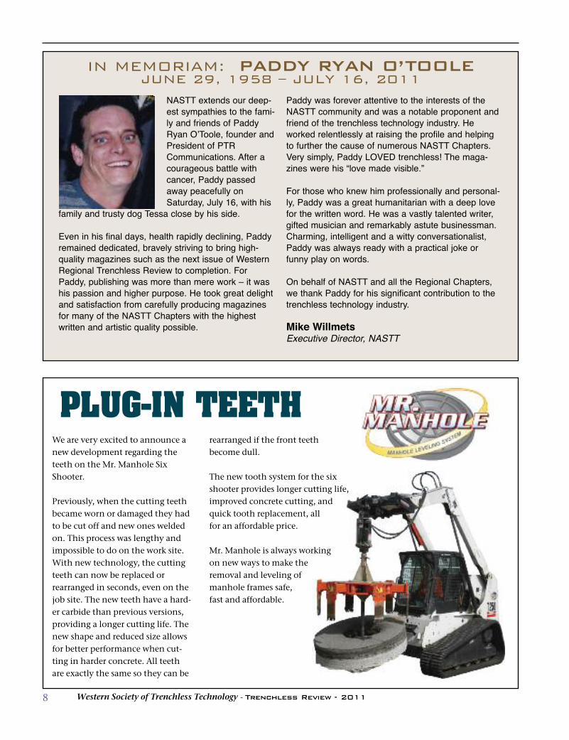
We are very excited to announce anew development regarding theteeth on the Mr. Manhole SixShooter.
Previously, when the cutting teethbecame worn or damaged they hadto be cut off and new ones weldedon. This process was lengthy andimpossible to do on the work site.With new technology, the cuttingteeth can now be replaced orrearranged in seconds, even on thejob site. The new teeth have a hard-er carbide than previous versions,providing a longer cutting life. Thenew shape and reduced size allowsfor better performance when cut-ting in harder concrete. All teethare exactly the same so they can be
rearranged if the front teethbecome dull.
The new tooth system for the sixshooter provides longer cutting life,improved concrete cutting, andquick tooth replacement, all for an affordable price.
Mr. Manhole is always working on new ways to make the removal and leveling of manhole frames safe, fast and affordable.
PLUG-IN TEETH

9Western Society of Trenchless Technology - Trenchless Review - 2011
The No-Dig Show this year inWashington, D.C., drew a recordcrowd to the Gaylord National Resort& Convention Center. The 20thannual show attracted 1,814 people,the second-highest attendance for aNo-Dig in North America (theInternational No-Dig in 2009 saw1,903 members come to Toronto). Nearly 140 exhibiting companies
featured products and industryadvancements in the 73,000-square-foot exhibition hall. There were also140 peer-reviewed technical paperspresented covering condition assess-ment and inspection, horizontaldirectional drilling, microtunneling,large-diameter tunnel, pipe bursting,auger boring, sliplining, cured-in-place pipe relining, and more.Of course, respected awards honor-
ing the people and projects thatshape the industry were given torecipients throughout the three-dayevent. These awards were presentedat various social engagements. Monday, March 28, saw the kick-
off breakfast where the 2011Trenchless Technology Person of theYear Award and the 2010Outstanding Papers in Rehabilitationand New Installation awards weregiven out. Attendees also experienced the
comedy routine of Greg Schwem,labeled by Chicago Magazine as“America’s favorite corporate funnyman.” Schwem tailored his routine,“Comedy With a Byte,” to the trench-less industry. He has previously per-formed to corporate crowds fromMcDonald’s, Microsoft, Motorola andUnited Airlines, among others.The annual Educational Fund
Auction and Reception was laterMonday night with raised funds sup-porting NASTT’s 11 student chapters.Since 2002, the auction has raisedmore than $356,000 and directedthose funds toward educationalactivities. This year, $72,000 wasraised through silent auction and –new this year – an eBay online auc-tion. Machine rentals, laptops, cam-eras, jewelry, golf clubs, various tripsand even maple syrup were some ofthe featured items.On Tuesday, the Gala Awards
Dinner saw the presentation of theTrent Ralston Award for YoungTrenchless Achievement, the JosephL. Abbot, Jr. Innovative ProductAwards, the NASTT Chairman’sAward for Outstanding LifetimeService, and the various winners ofthe 2010 Trenchless TechnologyProjects of the Year in Rehabilitationand New Installation. After the din-ner, the band Black Tie performed awide genre of music spanning fromearly classics to the latest hits.Wednesday’s closing luncheon cel-
ebrated the success of the 2011 show.
No-Dig takes on D.C.The annual show celebrates its 20th anniversary with a big crowd
No-Dig 2011 Report
The 2011 Municipal & UtilityAchievement Awards wereannounced during this event. Theseawards recognized the exceptionalachievement among American andCanadian municipalities and publicutilities. The 2012 No-Dig Show will be in
Nashville, Tenn., at the GaylordOpryland Resort & ConventionCenter, March 11-15. The deadline tosubmit a 300-word abstract onNASTT’s online form is June 30. No e-mail, mail or fax abstracts will beaccepted. George Ragula is the 2012 program
chair and says there will be anincreased emphasis on sustainabilityand cost efficiency for the trenchlessmarket. This will be the third No-Digevent in Tennessee, surely bringingback memories of past successfulshows.Visit www.nodigshow.com for
more information on the upcomingconvention.
Reprinted courtesy NASTT’S Trenchless Today.
The 2011 No-Dig Show attracted nearly 2,000 participants.
10 Western Society of Trenchless Technology - Trenchless Review - 2011
Dear Trenchless Professionals,
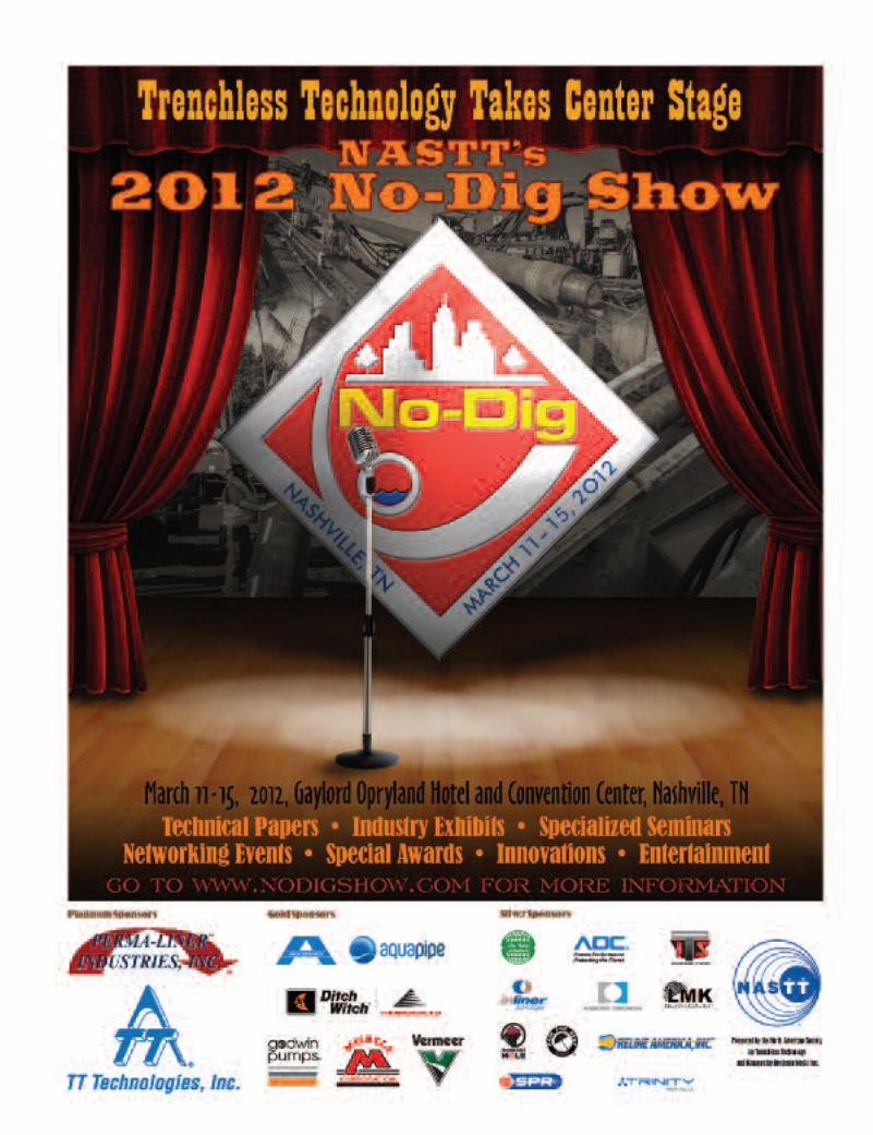
Nashville, home of country music’s hottest stars, will host
the industry’s premier trenchless technology event in North
America – NASTT’s No-Dig Show, the hottest ticket in town.
We invite you to join us March 11-15 at the beautiful and
well-appointed Gaylord Opryland Hotel.
Our 21st annual conference marks the third return of No-
Dig to Nashville, rousing a sense of nostalgia for many. When
we first met here a decade ago, some would say that it was a
turning point, a sort of renaissance for the organization and
the industry itself. The 2001 event sparked a renewed interest
in trenchless technology as a viable method to repair/replace
underground systems while minimizing surface disruption.
Since 2001, No-Dig has nearly doubled in size, keeping pace
with the rapid growth of our industry. Cutting-edge tech-
nologies are continually being developed and introduced to
the marketplace. Each year brings new products, new services
and new players. Projects are continuously pushing the
boundaries of what can be achieved with trenchless technolo-
gies. Our conference creates a unique opportunity for you to
see, hear and interact with leaders in the industry who drive
the trenchless marketplace today.
We have 155 technical papers in the conference program
packed with timely topics and useful information that you
can put to use right away. The papers and presenters are of the
highest quality, making for an excellent technical program.
We are pleased to announce the addition of a sixth track to
the paper schedule, offering you even more educational
opportunities!
That’s not all! The trenchless education provided at the No-
Dig show is unmatched. You can choose to attend one of our
pre- and post-conference courses on HDD, pipebursting, later-
als, new installation methods and CIPP lining. New this year,
we’re offering an expanded one-day “Introduction to
Trenchless Technology” course on Sunday, March 11, with
the latest advances in trenchless techniques.
Benefit from the in-depth sessions and courses offered at
No-Dig in more ways than one. For every 10 hours you
attend, you receive one continuing education unit to advance
your professional career.
The overall No-Dig program is focused on one objective:
helping you maximize your investment in trenchless tech-
nologies, services and applications. Owners, utilities and
municipalities can immediately benefit. You will learn how to
replace/repair and install pipelines with minimal excavation
while reducing the impact to your surroundings. You will find
that trenchless technology is not only the least disruptive
option, but oftentimes is the most cost-effective. The techni-
cal sessions and exhibitions are designed to provide you with
information you need to make the best possible decisions.
Starting with Monday’s Opening Kick-off Breakfast, you’ll
have plenty of opportunities to network with your industry
peers throughout the week. We also invite you to support our
annual Education Fund Auction by donating or bidding on
amazing items to help raise funds for NASTT’s educational
initiatives. This year’s Auction promises to be truly exciting
with a country-western theme and costume dress-up. Also
new this year, NASTT will unveil its Trenchless Technology
Hall of Fame awards at the Tuesday evening Gala Awards
Dinner. Stay tuned for more details!
Please mark your calendars for March 11-15 in Nashville,
where we hope you will join us as “Trenchless Takes Center
Stage.” We look forward to seeing you in attendance. For con-
ference updates and information, be sure to visit our website
at www.nodigshow.com.
Sincerely,
George Ragula
Kim Staheli
No-Dig 2012
George RagulaNo-Dig Program Chair
Trenchless Takes CenterStage in Nashville
Kim StaheliNo-Dig Program Vice-Chair
11Western Society of Trenchless Technology - Trenchless Review - 2011

12 Western Society of Trenchless Technology - Trenchless Review - 2011
All of the benefits of a national conference program in a smaller forum with a personalized touch! Come to San Jose, California and learn about the latest in Trenchless Technology from experts in the field. Registration includes an informative technical program and product exhibit area.
The conference is useful to public officials, engineers, utility company personnel, designers, and contractors alike who are involved with designing, constructing, rehabilitating, and managing underground utilities.
WESTERN REGIONAL NO-DIG CONFERENCE AND EXHIBITION: SAN JOSE, CA OCTOBER 3-4, 2011
For questions about the conference, call: Kate Wallin - 916.294.0095 Jason Lueke - 480.965.7417 Sam Ariaratnam - 480.965.7399
THE WESTERN CHAPTER OF NASTT IS HOSTING THE SEVENTH ANNUAL
REGISTER ONLINE AT: WWW.NASTT.ORG/WESTT
Platinum Sponsorship $1500
Gold Sponsorship $750
Silver Sponsorship $500
Bronze Sponsorship $350
Conference Registration Fees:
Early After 9/3
NASTT Member $275 $325
Non-Member* $325 $375
* Non-Member registration fee includes NASTT membership for one year (2012)
WYNDHAM HOTEL 1350 North 1st St San Jose, CA 95112 408.453.6200
Located 2 miles from the San Jose Airport
to get discounted room rates
13Western Society of Trenchless Technology - Trenchless Review - 2011
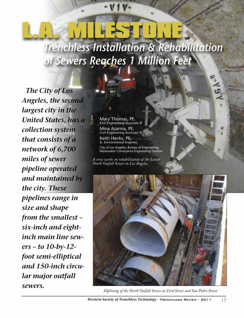
The City of LosAngeles, the secondlargest city in theUnited States, has acollection systemthat consists of anetwork of 6,700miles of sewerpipeline operatedand maintained bythe city. Thesepipelines range insize and shapefrom the smallest –six-inch and eight-inch main line sew-ers – to 10-by-12-foot semi-ellipticaland 150-inch circu-lar major outfallsewers.
L.A. MILESTONETrenchless Installation & Rehabilitation of Sewers Reaches 1 Million Feet
Mary Thomas, PE. Civil Engineering Associate III
Mina Azarnia, PE. Civil Engineering Associate III
Keith Hanks, PE, Sr. Environmental Engineer,
City of Los Angeles, Bureau of Engineering,Wastewater Conveyance Engineering Division
Sliplining of the North Outfall Sewer at 23rd Street and San Pedro Street
A crew works on rehabilitation of the LowerNorth Outfall Sewer in Los Angeles.
14 Western Society of Trenchless Technology - Trenchless Review - 2011
Historically most of these sewers
were constructed and repaired using
conventional cut and cover methods.
In cases where it is appropriate, tun-
neling has been used for new con-
struction. The City has also adopted
the use of trenchless methods for
rehabilitation of the sewer system.
Examples of some of the large sew-
ers that have been constructed or
rehabilitated with trenchless meth-
ods include:
• The 7.2-mile-long, 60” x 73” ellip-
tical Central Outfall Sewer com-
pleted in 1904 using both cut and
cover and tunneling. Half of this
sewer has just been rehabilitated
using trenchless methods, and the
design for the trenchless rehabilita-
tion of the second half of the sewer
has been completed.
• The 9.2-mile-long, 10.5’ x 12.25’
Lower North Outfall Sewer com-
pleted in 1924 using both cut and
cover and tunneling. It has recent-
ly been rehabilitated using trench-
less methods.
• The eight-mile-long, 150-inch
North Outfall Relief Sewer tunnel
completed in 1993.
• The 11-mile-long, 132-inch diame-
ter East Central Interceptor Sewer
tunnel completed in March 2005.
The City of Los Angeles collection
system also includes more than
100,000 maintenance holes and vari-
ous hydraulic structures such as
siphons, diversion structures and
junction structures.
Part of the City’s sewer system
dates back to the late 1800s. The size
of sewers and the materials used in
their construction have changed over
the years. The first known sewer, pri-
vately installed in 1863, was con-
structed of wood and connected the
Bella Union Hotel to the zanja (water
distribution ditch). The first known
public sewer, installed in 1873, was
500 feet long and located in
Commercial Street. It was also made
of wood.
The first major outfall sewer was a
combination of masonry construc-
tion and wood stave construction.
This sewer, which was known as the
Dockweiler sewer and was named
after the City Engineer who built it,
deteriorated rapidly and had a useful
life of only approximately 10 years.
The elliptical Central Outfall Sewer
replaced the Dockweiler sewer as the
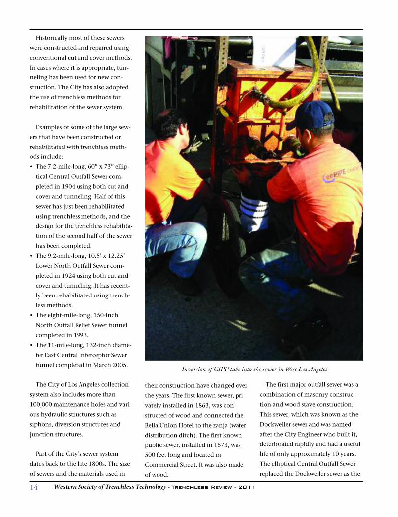
Inversion of CIPP tube into the sewer in West Los Angeles
15Western Society of Trenchless Technology - Trenchless Review - 2011
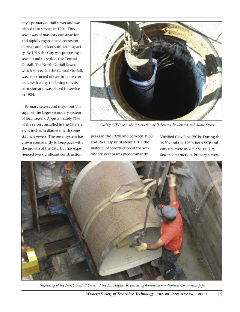
Sliplining of the North Outfall Sewer at the Los Angeles River, using 48-inch semi-elliptical Channeline pipe
city’s primary outfall sewer and was
placed into service in 1904. This
sewer was of masonry construction
and rapidly experienced corrosion
damage and lack of sufficient capaci-
ty. By 1916 the City was proposing a
sewer bond to replace the Central
Outfall. The North Outfall Sewer,
which succeeded the Central Outfall,
was constructed of cast-in-place con-
crete with a clay tile lining to resist
corrosion and was placed in service
in 1924.
Primary sewers and major outfalls
support the larger secondary system
of local sewers. Approximately 75%
of the sewers installed in the City are
eight inches in diameter with some
six-inch sewers. The sewer system has
grown consistently to keep pace with
the growth of the City, but has expe-
rienced two significant construction
peaks in the 1920s and between 1950
and 1960. Up until about 1919, the
material of construction of the sec-
ondary system was predominantly
Vitrified Clay Pipe (VCP). During the
1920s and the 1930s both VCP and
concrete were used for Secondary
Sewer construction. Primary sewers
Curing CIPP near the intersection of Robertson Boulevard and Alcott Street
16 Western Society of Trenchless Technology - Trenchless Review - 2011
were of masonry or tile protected concrete. Since the
1940s the Secondary Sewer system is almost entirely VCP,
and Primary Sewers were of T-lock-protected reinforced
or pre-stressed concrete pipe. The expansion of the City
sewer system is still ongoing with new projects currently
in the pre-design and design phases.
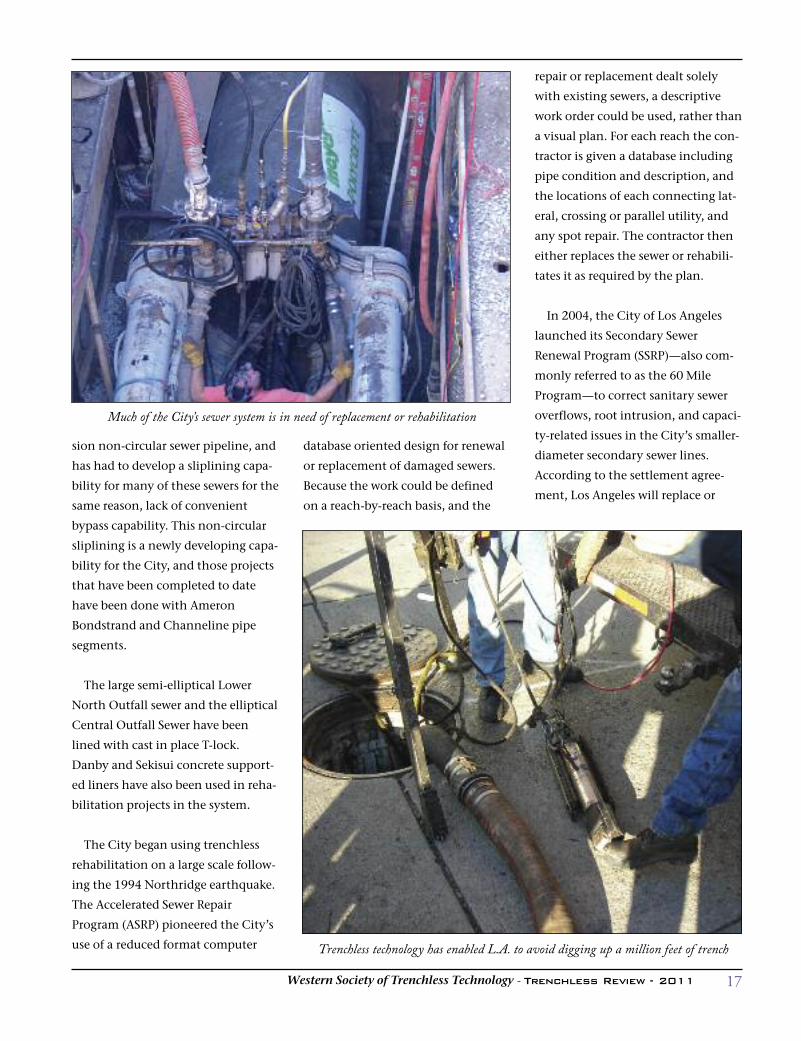
Much of the City’s collection system has reached the
point where replacement or rehabilitation is required.
The primary reasons for rehabilitation include corrosion,
root intrusion, and structural damage. Along with con-
structing new sewers, the Department of Public Works
has embarked on an aggressive program to upgrade the
sewer system and has entered into a settlement agree-
ment with the Environmental Protection Agency (EPA)
and other stakeholders. The City of Los Angeles uses both
traditional open-cut methods and a variety of trenchless
methods for rehabilitation and new installation. Such
trenchless means include sliplining, cured-in-place pipe,
cast-in-place grout-supported liners, microtunneling and
traditional tunneling. Pipe bursting and Horizontal
Directional Drilling (HDD) are other trenchless methods
that have been used when it has been appropriate.
The majority of the rehabilitation in the small-diame-
ter secondary system has been done using CIPP lining.
The City of Los Angeles regulates the materials that will
be used in constructing and rehabilitating the sewer sys-
tem. Approved materials are listed on the Bureau of
Engineering website in the Approved Products Tracking
System. The selection of the particular CIPP lining sys-
tem that will be used to rehabilitate any given sewer has
been left up to the open bidding process, and several
CIPP suppliers have installed their approved products in
the sewer system.
Large-diameter circular pipe rehabilitation has been
performed by sliplining since most of the major sewers
do not offer a convenient bypassing capability and must
be rehabilitated in the wet. As with CIPP products, the
materials used in sliplining large sewers must also come
from the list of products on the Approved Products
Tracking System. Large-diameter circular sliplining has
been predominantly done with Hobas pipe, and some
Spirolite.
The City has approximately 65 miles of large-dimen-
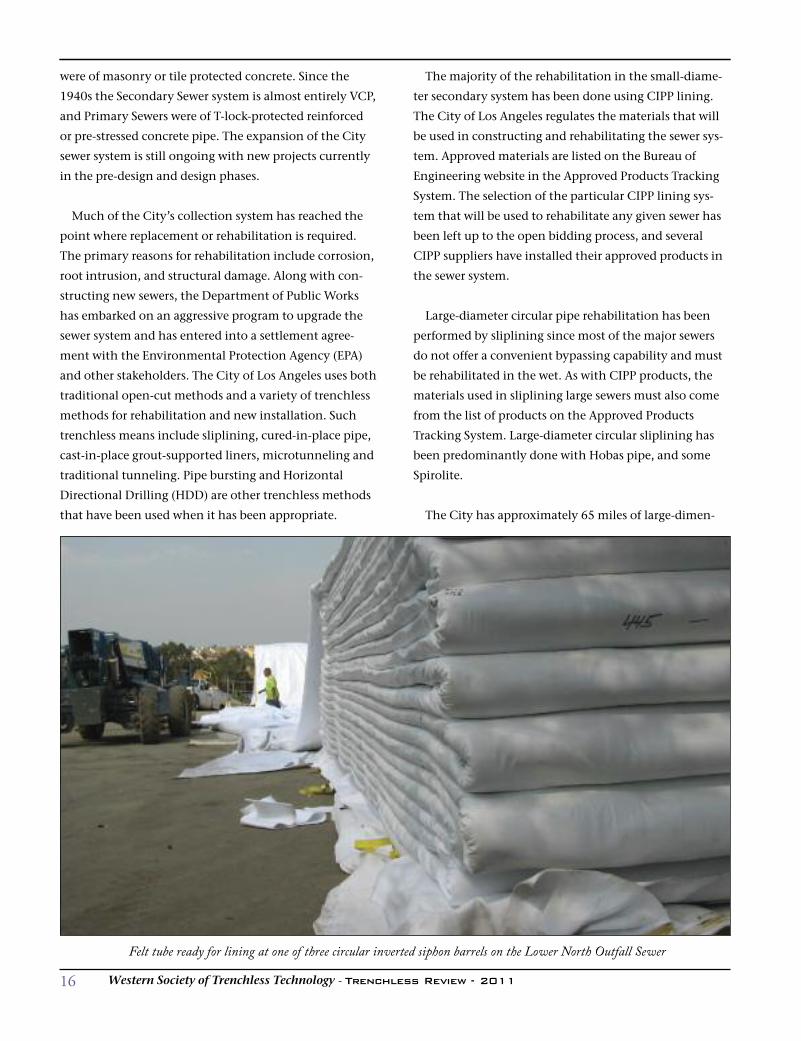
Felt tube ready for lining at one of three circular inverted siphon barrels on the Lower North Outfall Sewer
17Western Society of Trenchless Technology - Trenchless Review - 2011
sion non-circular sewer pipeline, and
has had to develop a sliplining capa-
bility for many of these sewers for the
same reason, lack of convenient
bypass capability. This non-circular
sliplining is a newly developing capa-
bility for the City, and those projects
that have been completed to date
have been done with Ameron
Bondstrand and Channeline pipe
segments.
The large semi-elliptical Lower
North Outfall sewer and the elliptical
Central Outfall Sewer have been
lined with cast in place T-lock.
Danby and Sekisui concrete support-
ed liners have also been used in reha-
bilitation projects in the system.
The City began using trenchless
rehabilitation on a large scale follow-
ing the 1994 Northridge earthquake.
The Accelerated Sewer Repair
Program (ASRP) pioneered the City’s
use of a reduced format computer
database oriented design for renewal
or replacement of damaged sewers.
Because the work could be defined
on a reach-by-reach basis, and the
repair or replacement dealt solely
with existing sewers, a descriptive
work order could be used, rather than
a visual plan. For each reach the con-
tractor is given a database including
pipe condition and description, and
the locations of each connecting lat-
eral, crossing or parallel utility, and
any spot repair. The contractor then
either replaces the sewer or rehabili-
tates it as required by the plan.
In 2004, the City of Los Angeles
launched its Secondary Sewer
Renewal Program (SSRP)—also com-
monly referred to as the 60 Mile
Program—to correct sanitary sewer
overflows, root intrusion, and capaci-
ty-related issues in the City’s smaller-
diameter secondary sewer lines.
According to the settlement agree-
ment, Los Angeles will replace or
Much of the City’s sewer system is in need of replacement or rehabilitation
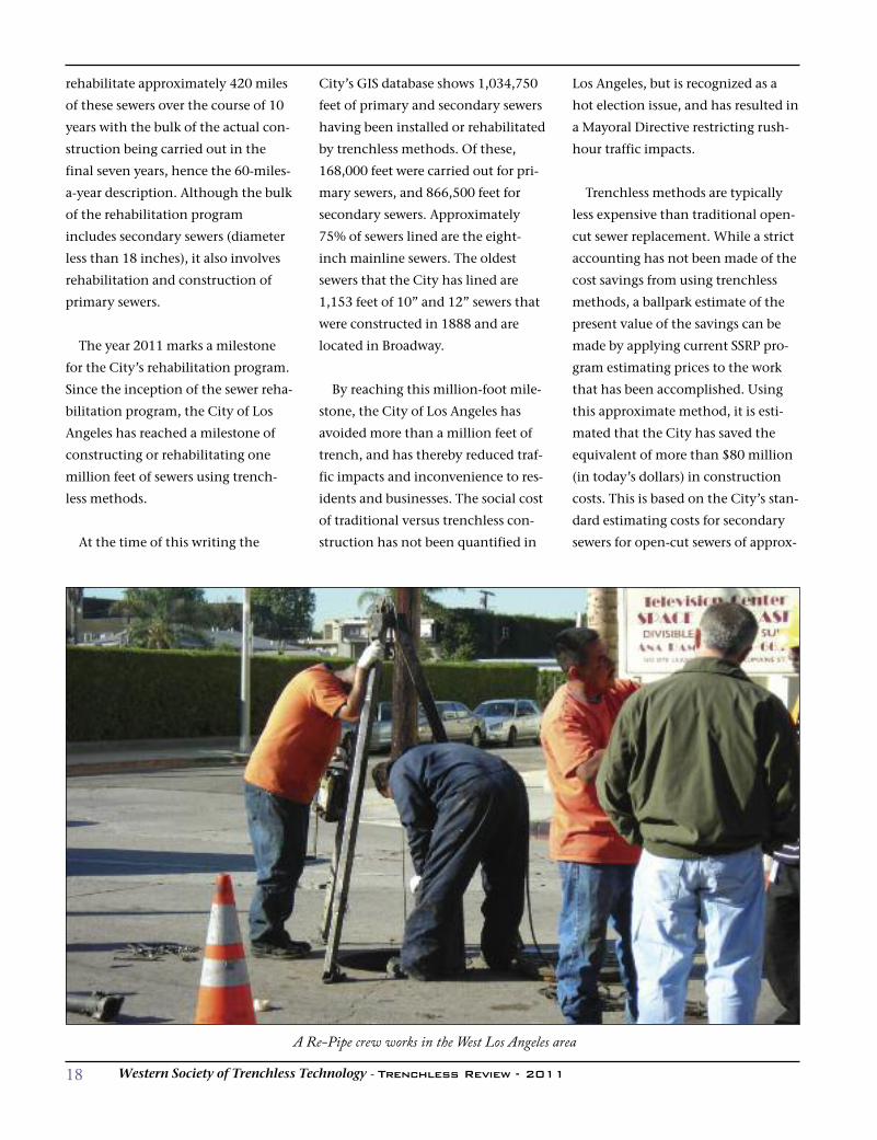
Trenchless technology has enabled L.A. to avoid digging up a million feet of trench
18 Western Society of Trenchless Technology - Trenchless Review - 2011
rehabilitate approximately 420 miles
of these sewers over the course of 10
years with the bulk of the actual con-
struction being carried out in the
final seven years, hence the 60-miles-
a-year description. Although the bulk
of the rehabilitation program
includes secondary sewers (diameter
less than 18 inches), it also involves
rehabilitation and construction of
primary sewers.
The year 2011 marks a milestone
for the City’s rehabilitation program.
Since the inception of the sewer reha-
bilitation program, the City of Los
Angeles has reached a milestone of
constructing or rehabilitating one
million feet of sewers using trench-
less methods.
At the time of this writing the
City’s GIS database shows 1,034,750
feet of primary and secondary sewers
having been installed or rehabilitated
by trenchless methods. Of these,
168,000 feet were carried out for pri-
mary sewers, and 866,500 feet for
secondary sewers. Approximately
75% of sewers lined are the eight-
inch mainline sewers. The oldest
sewers that the City has lined are
1,153 feet of 10” and 12” sewers that
were constructed in 1888 and are
located in Broadway.
By reaching this million-foot mile-
stone, the City of Los Angeles has
avoided more than a million feet of
trench, and has thereby reduced traf-
fic impacts and inconvenience to res-
idents and businesses. The social cost
of traditional versus trenchless con-
struction has not been quantified in
Los Angeles, but is recognized as a
hot election issue, and has resulted in
a Mayoral Directive restricting rush-
hour traffic impacts.
Trenchless methods are typically
less expensive than traditional open-
cut sewer replacement. While a strict
accounting has not been made of the
cost savings from using trenchless
methods, a ballpark estimate of the
present value of the savings can be
made by applying current SSRP pro-
gram estimating prices to the work
that has been accomplished. Using
this approximate method, it is esti-
mated that the City has saved the
equivalent of more than $80 million
(in today’s dollars) in construction
costs. This is based on the City’s stan-
dard estimating costs for secondary
sewers for open-cut sewers of approx-
A Re-Pipe crew works in the West Los Angeles area
19Western Society of Trenchless Technology - Trenchless Review - 2011
imately $125 per linear foot and an
estimated $30 per linear foot for
trenchless rehabilitation. The cost
per linear foot obviously would be
higher for primary sewers.
Building on the original computer
database design concept developed
for the ASRP Program, the City has
also been creative in developing a
proprietary software package called
SMARTS (Sewer Management
Automated Repair Tracking System)
for the Secondary Sewer Repair
Program. This program produces a
reduced format design and bidding
package, usually with no drawings,
that significantly reduces the cost
and time of preparing plans and
specifications. Employing state of the
art GIS technology, electronic plan
retrieval and sewer video, this pro-
gram brings all of the necessary
information for the design of sewer
rehabilitation projects to the engi-
neer’s desktop.
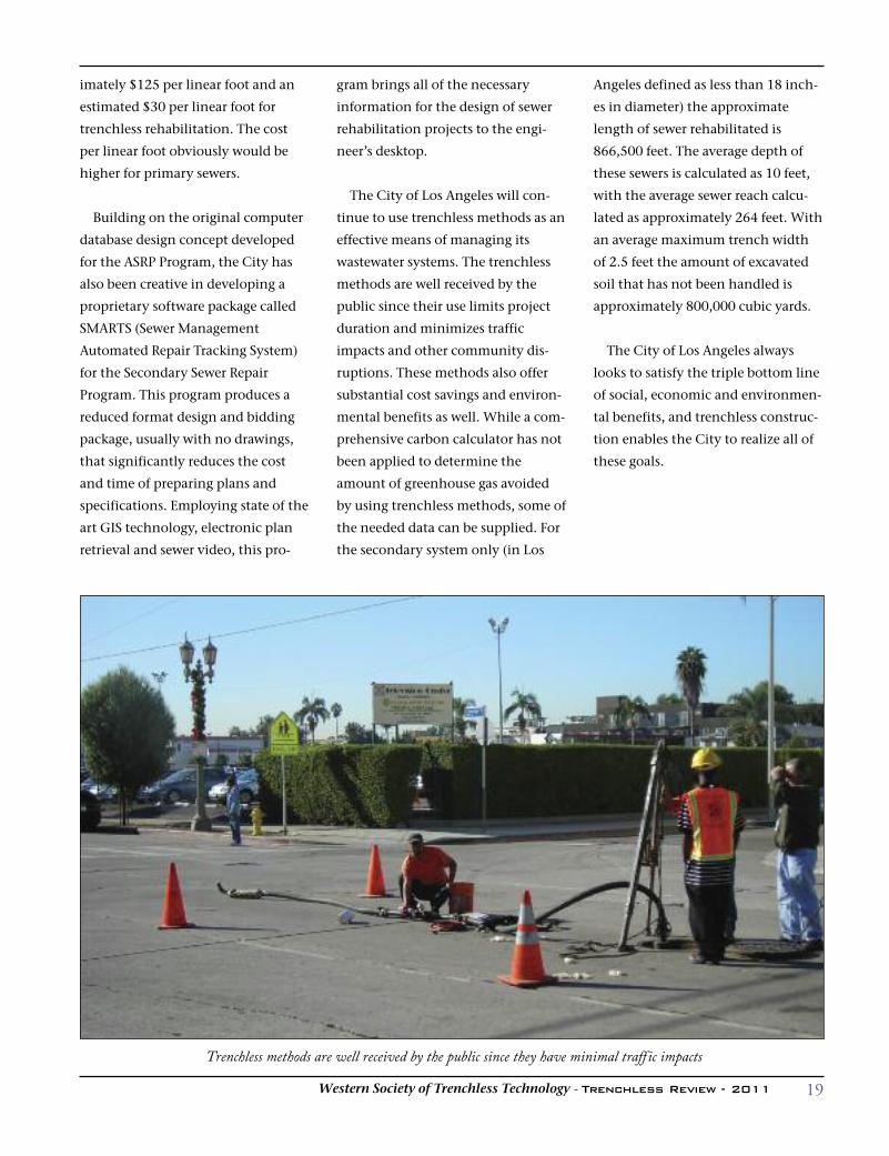
The City of Los Angeles will con-
tinue to use trenchless methods as an
effective means of managing its
wastewater systems. The trenchless
methods are well received by the
public since their use limits project
duration and minimizes traffic
impacts and other community dis-
ruptions. These methods also offer
substantial cost savings and environ-
mental benefits as well. While a com-
prehensive carbon calculator has not
been applied to determine the
amount of greenhouse gas avoided
by using trenchless methods, some of
the needed data can be supplied. For
the secondary system only (in Los
Angeles defined as less than 18 inch-
es in diameter) the approximate
length of sewer rehabilitated is
866,500 feet. The average depth of
these sewers is calculated as 10 feet,
with the average sewer reach calcu-
lated as approximately 264 feet. With
an average maximum trench width
of 2.5 feet the amount of excavated
soil that has not been handled is
approximately 800,000 cubic yards.
The City of Los Angeles always
looks to satisfy the triple bottom line
of social, economic and environmen-
tal benefits, and trenchless construc-
tion enables the City to realize all of
these goals.
Trenchless methods are well received by the public since they have minimal traff ic impacts
20 Western Society of Trenchless Technology - Trenchless Review - 2011
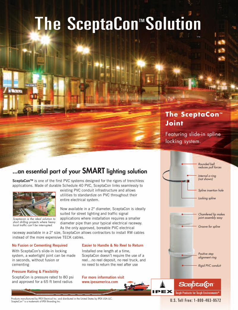
Chamfered lip makesjoint assembly easy
Internal o-ring (not shown)
Spline insertion hole
Groove for spline
Rigid PVC conduit
Locking spline
Rounded bell reduces pull forces
Positive stopalignment ring
The SceptaConTMSolution
SceptaConTM is one of the first PVC systems designed for the rigors of trenchlessapplications. Made of durable Schedule 40 PVC, SceptaCon links seamlessly to
existing PVC conduit infrastructure and allowsutilities to standardize on PVC throughout theirentire electrical system.
Now available in a 2" diameter, SceptaCon is ideallysuited for street lighting and traffic signalapplications where installation requires a smallerdiameter pipe than your typical electrical raceway.As the only approved, boreable PVC electrical
raceway available in a 2" size, SceptaCon allows contractors to install RW cablesinstead of the more expensive TECK cables.
...an essential part of your SMART lighting solution
The SceptaCon™
Joint
Featuring slide-in splinelocking system.
Tough Products for Tough Environments®
U . S . To l l F r e e : 1 - 8 0 0 - 4 6 3 - 9 5 7 2Products manufactured by IPEX Electrical Inc. and distributed in the United States by IPEX USA LLC. SceptaCon™ is a trademark of IPEX Branding Inc.
Sceptacon is the ideal solution toshort drilling projects where heavylocal traffic can't be interrupted.
No Fusion or Cementing RequiredWith SceptaCon’s slide-in lockingsystem, a watertight joint can be madein seconds, without fusion orcementing
Pressure Rating & FlexibilitySceptaCon is pressure rated to 80 psiand approved for a 65 ft bend radius
Easier to Handle & No Reel to ReturnInstalled one length at a time,SceptaCon doesn’t require the use of areel…no reel deposit, no reel truck, andno need to return the reel after use
For more information visitwww.ipexamerica.com
21Western Society of Trenchless Technology - Trenchless Review - 2011
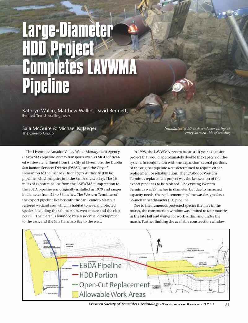
The Livermore-Amador Valley Water Management Agency
(LAVWMA) pipeline system transports over 30 MGD of treat-
ed wastewater effluent from the City of Livermore, the Dublin
San Ramon Services District (DSRSD), and the City of
Pleasanton to the East Bay Dischargers Authority (EBDA)
pipeline, which empties into the San Francisco Bay. The 16
miles of export pipeline from the LAVWMA pump station to
the EBDA pipeline was originally installed in 1979 and ranges
in diameter from 24 to 36 inches. The Western Terminus of
the export pipeline lies beneath the San Leandro Marsh, a
restored wetland area which is habitat to several protected
species, including the salt marsh harvest mouse and the clap-
per rail. The marsh is bounded by a residential development
to the east, and the San Francisco Bay to the west.
In 1998, the LAVWMA system began a 10-year expansion
project that would approximately double the capacity of the
system. In conjunction with the expansion, several portions
of the original pipeline were determined to require either
replacement or rehabilitation. The 1,750-foot Western
Terminus replacement project was the last section of the
export pipelines to be replaced. The existing Western
Terminus was 27 inches in diameter, but due to increased
capacity needs, the replacement pipeline was designed as a
36-inch inner diameter (ID) pipeline.
Due to the numerous protected species that live in the
marsh, the construction window was limited to four months
in the late fall and winter for work within and under the
marsh. Further limiting the available construction window,
Installation of 60-inch conductor casing atentry on west side of crossing
Large-DiameterHDD ProjectCompletes LAVWMAPipelineKathryn Wallin, Matthew Wallin, David Bennett,Bennett Trenchless Engineers
Sala McGuire & Michael K. JaegerThe Covello Group
22 Western Society of Trenchless Technology - Trenchless Review - 2011
work hours were restricted to 7 AM to 6 PM to limit impacts to
the nearby residential community. Trenchless construction
methods were essential for the majority of the pipeline
replacement to reduce the environmental and social impacts
from construction. The project also included approximately
550 feet of open-cut construction on the eastern end of the
project. The trenchless construction methods that were con-
sidered for installing the 1,200-foot, 36-inch ID pipe across
the marsh included microtunneling and horizontal direction-
al drilling (HDD).
Microtunneling 36-inch ID pipe is very common; however,
guidance becomes less accurate for small-diameter pipe as
drive lengths increase beyond 600 feet. Because of environ-
mental restrictions, it was impossible to place an intermediate
shaft in the middle of the marsh to reduce drive lengths. In
addition, the shafts required for microtunneling would need
to be watertight to prevent seepage of groundwater into the
shaft which could result in flooding and/or settlement
around the shafts. The need for watertight shaft construction
methods would further increase the cost and construction
schedule. Due to the long drive length, it was also likely that
intermediate jacking stations would be required to microtun-
nel the 1,200-foot drive, further increasing risk and cost.
Using HDD to install 1,200 feet of pipe is standard practice;
however, the diameter of pipe required for this project is near
the upper end of HDD capabilities. Installing large-diameter
pipelines with HDD requires an annular space with approxi-
mately six inches of radial overcut to reduce friction during
pullback. In soft soils, such as Young Bay Mud, a large HDD
bore diameter can collapse and cause delays in construction,
increased costs, and possible settlement damage. In addition,
the risk of hydrofracture is significantly higher with HDD
than with microtunneling. Due to the environmental permit-
ting requirements, drilling fluid hydrofracture risk needed to
be aggressively mitigated.
After considering the required length, diameter, construc-
tion schedule, risks, estimated cost and anticipated soil condi-
tions, HDD was selected as the more applicable construction
method for the Western Terminus Replacement Project.
Design of the Western Terminus project was awarded to
Brown and Caldwell in January of 2010, with geotechnical
subconsultant DCM/GeoEngineers, trenchless subconsultant
Bennett Trenchless Engineers, and construction manager The
Covello Group. Final design was completed in June 2010,
only six months after notice to proceed. The design timeline
of the project was considerably more compressed than typical
projects of this size in order for construction of the pipeline to
occur during the construction window of 2010.
The geotechnical investigation for the entire LAVWMA
expansion and rehabilitation project was conducted in 1998
by DCM/Joyal Engineering (now GeoEngineers). There were
four borings performed for the Western Terminus portion of
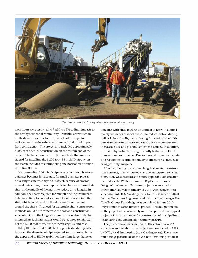
34-inch reamer on drill rig about to enter conductor casing
23Western Society of Trenchless Technology - Trenchless Review - 2011
the pipeline in addition to four borings that had been previ-
ously performed in the area for other projects. The existing
eight borings showed that the soil in the upper 20 feet was
predominantly soft to medium stiff fat and organic clays, geo-
logically identified as Young Bay Mud. The upper layer of
Young Bay Mud was underlain by a layer of stiff lean clay and
medium-dense sand, identified as Old Bay Mud. Groundwater
levels were within 10 feet of the ground surface.
Young Bay Mud is under-consolidated soft clay, is very
compressible, and is susceptible to high settlement and
hydrofracture risks. Old Bay Mud is typically normally-con-
solidated medium-stiff to hard clays and medium-dense to
dense silty sand, and is much less susceptible to settlement
and hydrofracture. Therefore, due to the environmental
restrictions within the marsh it was imperative to reduce the
risks associated with HDD construction by locating the bore
in the deeper Old Bay Mud as much as possible.
The west side of the crossing was chosen as the entry point
for the HDD crossing due to the much larger work area avail-
able. Locating the rig on the west side also helped to mini-
mize noise impacts to the residential neighborhood on the
east side of the crossing. To site as much of the bore as possi-
ble in the more competent Old Bay Mud, the HDD bore align-
ment used steep entry and exit angles; the steep angles were
selected to ensure that the bore reached a depth of 25 feet
before starting the vertical curves. It was important that this
depth be attained to ensure steering response in the stiffer
Old Bay Mud. Conductor casing was specified at the entry to
extend through the upper weaker soils into the deeper Old
Bay Mud. This geometry resulted in the bore reaching a maxi-
mum depth of approximately 70 feet below the ground sur-
face. A horizontal curve was required to remain largely within
the existing LAVWMA easement.
Pullback-load and pipe-stress analyses were performed for
this alignment using the ASCE Pipelines Guidelines. Based on
the analysis of pullback loads and pipe stresses, HDPE and
FPVC pipe materials were determined to be suitable for the
project. Steel pipe was not considered due to the corrosive
nature of the organic bay soils and the treated effluent, as well
as the tight geometry. The 36-inch ID FPVC with the required
stiffness class was not available within the short construction
schedule, therefore 42-inch OD DR 13.5 (and DR 21 for the
open-cut section) HDPE pipe was selected as the carrier pipe.
A detailed hydrofracture evaluation was conducted to help
optimize the design to reduce the risk of hydrofracture.
Hydrofracture calculations were performed according to the
Delft Cavity Expansion Model and were based on the soils
described in the Geotechnical Report and assumed drilling
fluid properties and means and methods. The hydrofracture
analysis results indicated that there was a heightened risk of
hydrofracture near the exit point. Therefore, conductor casing
was specified at the exit point to reduce risks of drilling fluids
escaping the bore, as well as to provide additional bore stabili-
ty in the soft Young Bay Mud.
The work area at the HDD entry point included a section of
an elevated bike path that crossed east-west over the marsh.
The work area needed to include a bike path detour around
the site to ensure public safety and uninterrupted access. The
work area on the eastern end of the alignment was insuffi-
cient to allow layout of the full length of fused pipeline with-
out restricting access to residents and traffic. Therefore, to
reduce impacts, the pipeline was designed to be fused in two
600-foot segments and staged in the work area and adjacent
park. The two segments would then be fused during a three-
hour pause in the pullback operation, slightly increasing the
risk of the pipe becoming stuck. However, fusing two seg-
ments during pullback is relatively common and the risk was
considered reasonable.
Bids for the Western Terminus Replacement Project were
opened on July 21, 2010. Notice to proceed was provided on
August 1, 2010 to the winning team, KJ Woods, with The
HDD Company as the HDD subcontractor. Mobilization also
included environmental training for all construction person-
nel and hand clearing wetland and upland plants to minimize
disturbance to the protected species. At the entry, 60-inch
conductor casing was installed at the entry to prevent
hydrofracture and bore collapse.
The 10-inch pilot bore began on October 8, 2010, and
reached the exit point in four days. There were several
hydrofractures which occurred during the first 850 feet of the
pilot bore. Unfortunately, downhole pressures were not moni-
tored, so it is difficult to assess the reason for the hydrofrac-
tures. The soils at the exit point were more competent than
anticipated and the bore hole was showing no signs of col-
lapse. Therefore, because the chance of hydrofracture is great-
est during the pilot bore, the contractor submitted a proposal
to eliminate the conductor casing on the exit side of the bore
and provide a credit to the owner.
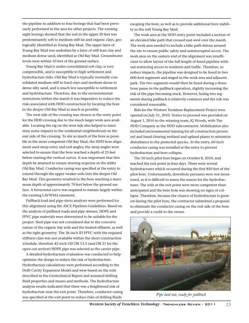
Pipe laid out, ready for pullback
24 Western Society of Trenchless Technology - Trenchless Review - 2011
The contractor reamed the bore to 58 inches over the
course of two weeks. The first segment of the 42-inch DR 13.5
HDPE was attached to a bore hole swabber, which is used to
stabilize the soil surrounding the bore hole, and then
attached to the drill pipe for pullback. After the first segment
of HDPE pipe was pulled about 500 feet into the ground, pull-
back stopped and the second 600-foot segment was fused to
the first. The pullback process began on October 28, 2010,
and was completed in 19.5 hours, including the three hours
of downtime required to fuse the two sections of pipe togeth-
er. The average rate for HDPE pipe pull was 30 feet in five min-
utes; however, pumping and removal of displaced drilling
fluid and bay mud as well as filling the HDPE pipe with water
to counteract the buoyancy were the most time-consuming
parts of the process. After the 1,200 feet of HDD pipe and 550
feet of open-cut pipe construction was complete, the contrac-
tor tied the new Western Terminus to the EBDA pipeline and
the new LAVWMA export pipelines began flowing on
December 8, 2010. Demobilization and site restoration were
completed on January 14, 2011, one day before the permit
expired.
There were several challenges encountered in the design
and construction of the HDD crossing for the Western
Terminus of the LAVWMA Export Pipeline Project. The pri-
mary challenge was the accelerated design and construction
schedule. The complete schedule from award of design to
completion of construction was less than one year. The accel-
erated schedule was facilitated by the availability of geotech-
nical data prior to award of design, extensive coordination
within the design team and with the owner, and early and
ongoing discussions with HDD contractors. During design
the team solicited input and feedback from various HDD con-
tractors to solve the challenges regarding work area con-
straints, ensuring emergency vehicle access, and bike path
bypass. The narrow construction window required effective
communication between the contractor, designer, and owner
to resolve issues in an efficient manner.
The site geotechnical conditions were challenging for a
large-diameter HDD installation due to the high risk of settle-
ment, hydrofracture, and bore collapse in the upper layer of
weak Young Bay Mud. These difficulties were overcome
through the use of conductor casing through the Young Bay
Mud to maintain bore stability, locating the majority of the
bore within the more competent lower Old Bay Mud, and
increasing the depth of cover to reduce the risks of hydrofrac-
tures and settlement.
The successful completion of this project marks the overall
completion of the LAVWMA Export Pipeline Project begun
over a decade earlier. The project’s final link, completed using
HDD, also underscores the significant incremental advance-
ments in HDD practice that ensured protection of sensitive
species and minimized disruption to nearby residents.
25Western Society of Trenchless Technology - Trenchless Review - 2011
AUI Inc. was, along with other quali-
fied companies, invited to bid on a
project to slipline aging and failing
concrete sewer mains going into the
privately held Central Valley Water
Reclamation Facility in Utah.
As the saying goes, “Go big or stay
home.” AUI went big, so to speak, and
was the successful bidder even though
AUI is headquartered many hundreds
of miles from the facility.
The lines to be sliplined are not only
the largest in Utah, but also AUI Inc.’s
largest slipline pipe size to date.
The biggest sewer line in AUI’s home
state of New Mexico is less than 80
inches in diameter, says AUI trenchless
division manager Mike Rocco. “We put
a 74-inch pipe inside a 78-inch line
once, and that was our biggest sliplin-
ing job before Central Valley.
“We realized that the Central Valley
job was going to be a little bit different
from our usual work.”
Based in Albuquerque but operating
across a wide geographic span, AUI
offers a wide range of construction and
engineering services. From specializing
in pipe- and utility-related projects
when it began as Albuquerque
Underground in the early 1980s, it has
expanded its expertise and work to
include bridges, paving, channels,
heavy dirtwork and more, always main-
taining safety and quality as top priori-
ties.
“Our specialty here at AUI is sliplin-
ing and pipebursting, but we do other
things,” Rocco says. “We’re a diversified
company.”
Now, about the Central Valley Water
Reclamation Facility: The plant, located
in Salt Lake City a bit west of the
Veterans Memorial Highway, was creat-
ed in the 1970s to meet the stringent
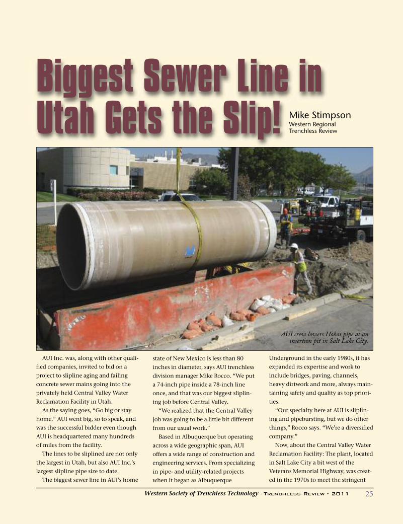
Biggest Sewer Line inUtah Gets the Slip! Mike Stimpson
Western Regional Trenchless Review
AUI crew lowers Hobas pipe at aninsertion pit in Salt Lake City.
26 Western Society of Trenchless Technology - Trenchless Review - 2011
Congressional Clean Water Act of 1972.
Central Valley board members repre-
sented districts and cities which operat-
ed five antiquated wastewater treat-
ment plants that fell short of the law’s
standards.
The facility was built on property
owned by one of the centrally located
board members and covers roughly 168
acres. The plant is designed to treat 75
million gallons of waste daily and
serves over a half-a-million customers
on a 24-7 schedule.
The demanding work was performed
in Salt Lake City in September and
October of 2010.
AUI’s project consisted of sliplining
the existing 84-inch i.d. RCP with 82-
inch o.d. fiberglass-reinforced polymer
mortar pipe from Hobas Pipe USA, and
sliplining 54-inch RCP with 52-inch
Hobas pipe.
Texas-based Hobas was chosen as
pipe supplier by Central Valley’s in-
house engineers based on its product’s
tight tolerances and high quality for
years of uninterrupted service.
AUI was able to accomplish the sli-
plining project by first utilizing
Southwest Sewer Services to clean and
CCTV the lines. Once this was accom-
plished, AUI was successful in sliplining
1,270 LF of 82-inch pipe and 864 LF of
52-inch pipe.
Some of the early concerns of the
project were due to the distance from
AUI’s home office. AUI had to ensure
the careful coordination of subcontrac-
tors, which also were coming from
Albuquerque, ensuring that schedules
were met and good communications
were always in place.
Due to all the quality and safe work
performed, the project was completed
on time and on budget.
“The customer was impressed,”
Rocco says. “This was their first time
utilizing trenchless technologies, and
they are already planning future proj-
ects on other areas of their lines utiliz-
ing the slipline method.
“AUI extends a note of special thanks
to our project superintendent, Archie
Lucero, and project foreman Dartanyan
Wofford for all their hard work and
dedication to the project.
“We would also like to recognize the
project’s subcontractors: Bogan Brothers
Painting, who handled the specialized
manhole coatings with Zeborn; Condeck
Corporation, who grouted the annular
space; and SW Sewer, who cleaned and
CCTV inspected the lines before and
after construction.”
Project DetailsProject Name: Central Valley RoadSewer RehabilitationLength and Diameters: 1,270 feet of82-inch, and 864 feet of 52-inchGeneral Contractor: AUI Inc,Albuquerque, NMEngineer: Ron Roberts, P.E., Salt Lake City, UTOwner: Central Valley WaterReclamation Facility
Pipe Bursting
Slip
Lining
Utilities
Heavy
Highway
TrenchlessTechnology
Manhole
RehabNationally
RecognizedSafetyProgram
For additional information, contact Michael Rocco(505) 242-4848, Ext. 3004 or [email protected] New Mexico Contractor License No. 20617
Licensed in Arizona, California, Colorado, New Mexico, Texas, and Utah
Two Offices in New Mexico
7420 Reading Avenue SE
Albuquerque, NM 87105
240 South Crawford
Las Cruces, NM 88007
27Western Society of Trenchless Technology - Trenchless Review - 2009
The Rutherford Pipeline Rehabilitation
project was bid in the fall of 2009.
Construction began in February 2010 and was
largely completed by June 2010. The existing
pipeline had suffered significant corrosion
leaks and had been repaired at 17 locations in
recent years. The trenchless pipe bursting
process was used successfully to complete the
project.
Faced with the prospect of more leakage on
the Rutherford water transmission line, the
City of St. Helena, California, planned to
replace 2,627 linear feet of 12-inch steel water
main. The existing 12-inch welded steel pipe
is located under a drainage ditch over most of
the alignment that further complicates all
excavations and would make an open-cut
project extremely difficult and costly, and
would encroach onto Highway 29. The City
needed a less intrusive replacement method
than open-cut construction. The existing
alignment is in a very narrow right-of-way
between heavily traveled Highway 29 to the
east and the Napa Valley Wine Train railroad
to the west.
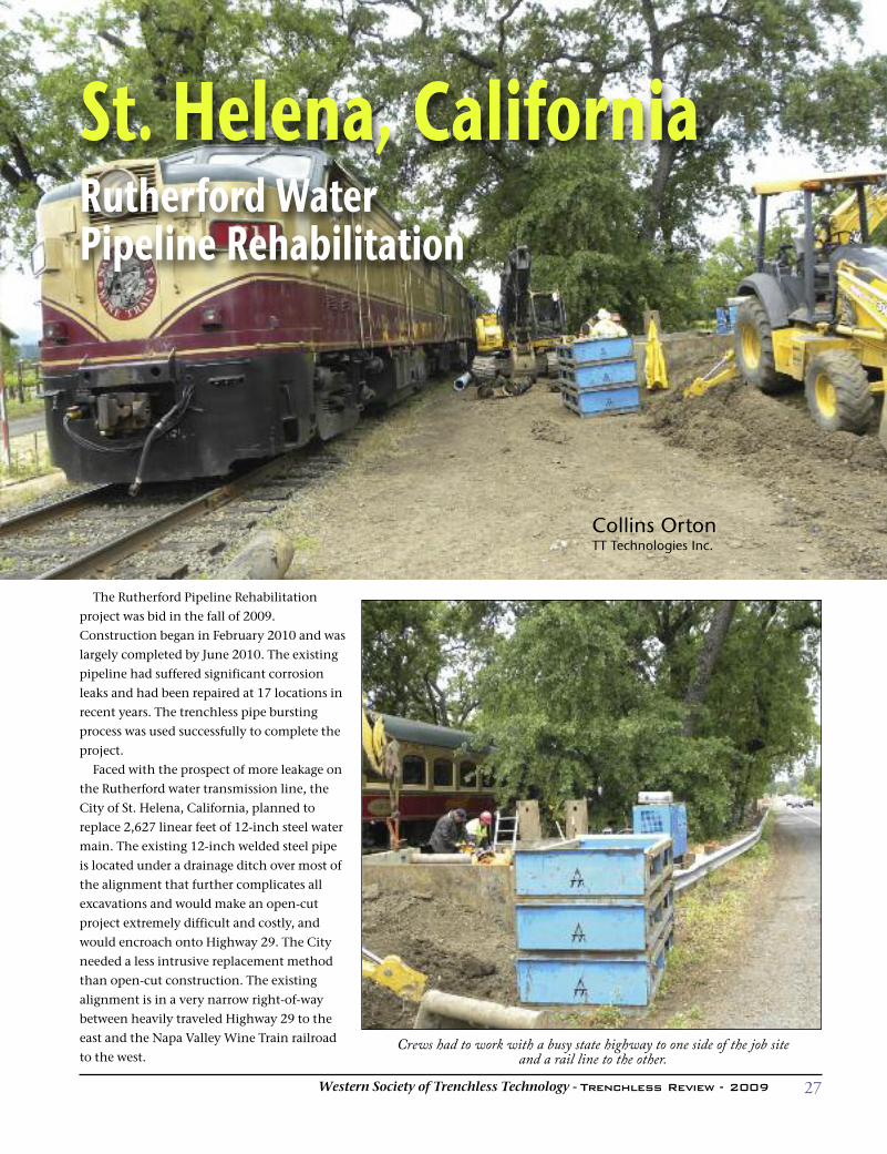
St. Helena, CaliforniaRutherford Water Pipeline Rehabilitation
Collins OrtonTT Technologies Inc.
Crews had to work with a busy state highway to one side of the job site and a rail line to the other.
28 Western Society of Trenchless Technology - Trenchless Review - 2011
More leaks in the line were predicted, so pipe replacement
was considered. Maintaining a reliable source of water to the
city and surrounding area in the Napa Valley was critical. The
engineer for the City was in need of a repair solution for this
section of the water transmission pipeline. Up to this point,
repairs had been made mostly with full-circle repair clamps.
This type of repair is costly and is usually done as an emer-
gency, leaving the pipeline out of service for a period of time
while repairs are completed.
In the fall of 2009, the city publicly bid a project to replace
the aging pipeline using the static pipe bursting method. The
successful bidder, Team Ghilotti of Petaluma, California, was
awarded the contract. Trenchless pipe bursting was chosen for
the project because the section of main ran along the high-
way and was constricted on the other side by the Wine Train.
Numerous utilities were also in the same alignment, many in
very close proximity to the 12-inch main. Another element
became apparent; the entire run of the 12-inch steel pipe was
joined, at 40-foot intervals, with Style 38 Dresser Couplings.
This would prove to be a major challenge to successful pipe
bursting. A conventional open-cut construction project
would have forced the city to take a lane in the state-con-
trolled highway; this was not an option. Another scheduling
element required getting the project completed before the
grape harvesting season, or “Crush” as it is known locally.
Harvesting grapes in this region is a major component in pro-
ducing some of the finest wines in the world.
PROJECT BACKGROUND After a wet winter that pushed the project two-and-a-half
months off schedule, Team Ghilotti, Inc. was under pressureto get the project started. After locating and removing allknown couplings and repairs on the welded steel pipeline,crews constructed machine pits. From these launching andreceiving pits, spaced approximately 400 lineal feet from eachother, crews attempted to install the 12-inch fusible C900PVC pipeline. Fusible PVC pipe was attached to the burstinghead and cutter assembly. A “floating” pulling head for thefusible PVC pipe is used to isolate the actions of the burstinghead from the string of new pipe.The pipe was launched, but the bursting/splitting opera-
tion did not go as planned. The welded steel pipe was splitsuccessfully but progress was stopped in the first 40 lineal feetdue to the Dresser couplings. The contractor was compelledto dig up each Dresser coupling to make ant forward progress.Over the next three days, with only 120 lineal feet of progressmade, the project was in need of a new technical supportteam.The couplings added several inches to the diameter of the
pipe. Team Ghilotti contacted trenchless equipment manu-facturer TT Technologies, Inc., of Aurora, Illinois, to brain-storm on a different method to split the pipe and couplings,
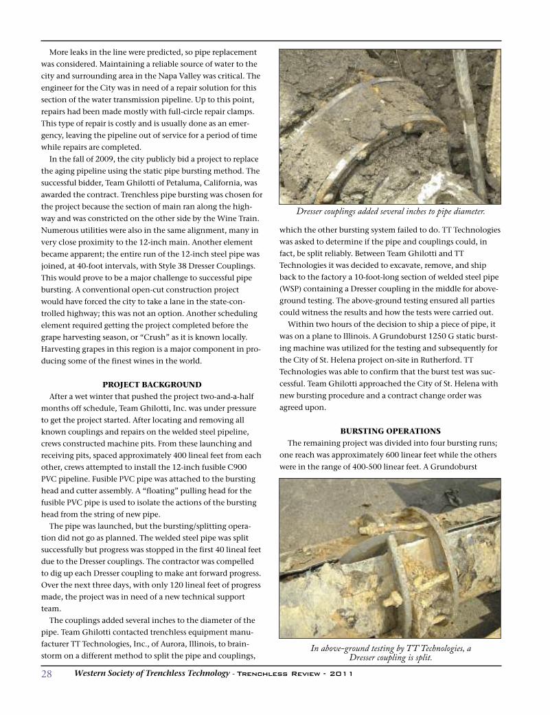
which the other bursting system failed to do. TT Technologieswas asked to determine if the pipe and couplings could, infact, be split reliably. Between Team Ghilotti and TTTechnologies it was decided to excavate, remove, and shipback to the factory a 10-foot-long section of welded steel pipe(WSP) containing a Dresser coupling in the middle for above-ground testing. The above-ground testing ensured all partiescould witness the results and how the tests were carried out.
Within two hours of the decision to ship a piece of pipe, it
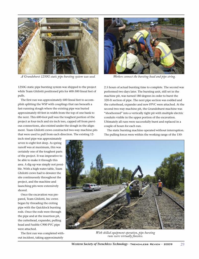
was on a plane to Illinois. A Grundoburst 1250 G static burst-
ing machine was utilized for the testing and subsequently for
the City of St. Helena project on-site in Rutherford. TT
Technologies was able to confirm that the burst test was suc-
cessful. Team Ghilotti approached the City of St. Helena with
new bursting procedure and a contract change order was
agreed upon.
BURSTING OPERATIONS The remaining project was divided into four bursting runs;
one reach was approximately 600 linear feet while the others
were in the range of 400-500 linear feet. A Grundoburst
Dresser couplings added several inches to pipe diameter.
In above-ground testing by TT Technologies, a Dresser coupling is split.
29Western Society of Trenchless Technology - Trenchless Review - 2009
1250G static pipe bursting system was shipped to the project
while Team Ghilotti positioned pits for 400-500 lineal feet of
pulls.
The first run was approximately 600 lineal feet to accom-
plish splitting the WSP with couplings that ran beneath a
fast-running slough where the existing pipe was buried
approximately 60 feet in width from the top of one bank to
the next. This 600-foot pull was the toughest portion of the
project as four-inch and six-inch tees, capped off from previ-
ous connections, also existed under the slough in the align-
ment. Team Ghilotti crews constructed two-way machine pits
that were used to pull from each direction. The existing 12-
inch steel pipe was approximately
seven to eight feet deep. As spring
runoff was at maximum, this was
certainly one of the toughest parts
of the project. It was imperative to
be able to make it through this
area. A dig-up was simply not possi-
ble. With a high water table, Team
Ghilotti crews had to dewater the
site continuously throughout the
project, and the machine and
launching pits were extensively
shored.
Once the excavation was pre-
pared, Team Ghilotti, Inc crews
began by threading the exiting
pipe with the Quicklock bursting
rods. Once the rods were through
the pipe and at the insertion pit,
the cutterhead, expander, pulling
head and Fusible C900 PVC pipe
were attached.
The first run was completed with-
out incident, taking approximately
2.5 hours of actual bursting time to complete. The second was
performed two days later. The bursting unit, still set in the
machine pit, was turned 180 degrees in order to burst the
320-ft section of pipe. The next pipe section was rodded and
the cutterhead, expander and new FPVC were attached. At the
second two-way machine pit, the Grundoburst machine was
“shoehorned” into a vertically tight pit with multiple electric
conduits visible in the upper portion of the excavation.
Ultimately all runs were successfully burst and replaced in a
couple of hours for each run.
The static bursting machine operated without interruption.
The pulling forces were within the working range of the 150-
A Grundoburst 1250G static pipe bursting system was used. Workers connect the bursting head and pipe string.
With skilled equipment operation, pipe bursting runs were virtually flawless.
30 Western Society of Trenchless Technology - Trenchless Review - 2011
ton capacity machine. The cutter and expander reliably split,
cut and expanded the 12-inch steel pipe and the steel Dresser
couplings for each bursting run.
LESSONS LEARNEDAs the project concluded, the contractor had become quite
skilled at operating the specialized bursting equipment. The
pipe bursting runs were virtually flawless. New 12-inch FPVC
pipe was safely and successfully installed. Representatives
from the City of St. Helena were very pleased with the pro-
ject’s progress and successful completion. Once the new
fusible PVC pipe was installed it was connected to the existing
piping, a connection to a temporary pump station was made,
and a handful of other connections were
made for water services and fire service.
The line was pressure tested successfully
and the city was extremely pleased to
have the project completed. With 35 years
of experience in the underground busi-
ness, Team Ghilotti was impressed by this
project. Looking back, digging up repair
clamps may not have been necessary.
The “Lessons Learned” representative
for the city stated that in future projects,
they would more closely specify the pipe
bursting system to be utilized. Because of
this project, splitting 12-inch welded steel
pipe coupled with Dresser type couplings
has been well documented. This will help
future project designers to have the prop-
er equipment for similar projects.
Because of the failures early in the proj-
ect it is quite apparent that there is a need
for advance testing or proven systems to
be used. Substantial expense, lost time
and high stress levels can be avoided.
What started out as a major pipeline
replacement project with great difficulty
splitting 12-inch steel pipe developed into
a successful conclusion. Efforts made by
the contractor, the city and the pipe
bursting technology provider to test and
verify the pipe bursting process resulted
in a good model of cooperation that led to
successful completion of the project.
Going forward the city is interested in
doing more of this work; however, fund-
ing is not available for those projects at
this time.
UNDERgRoUND SPEciALiSTS
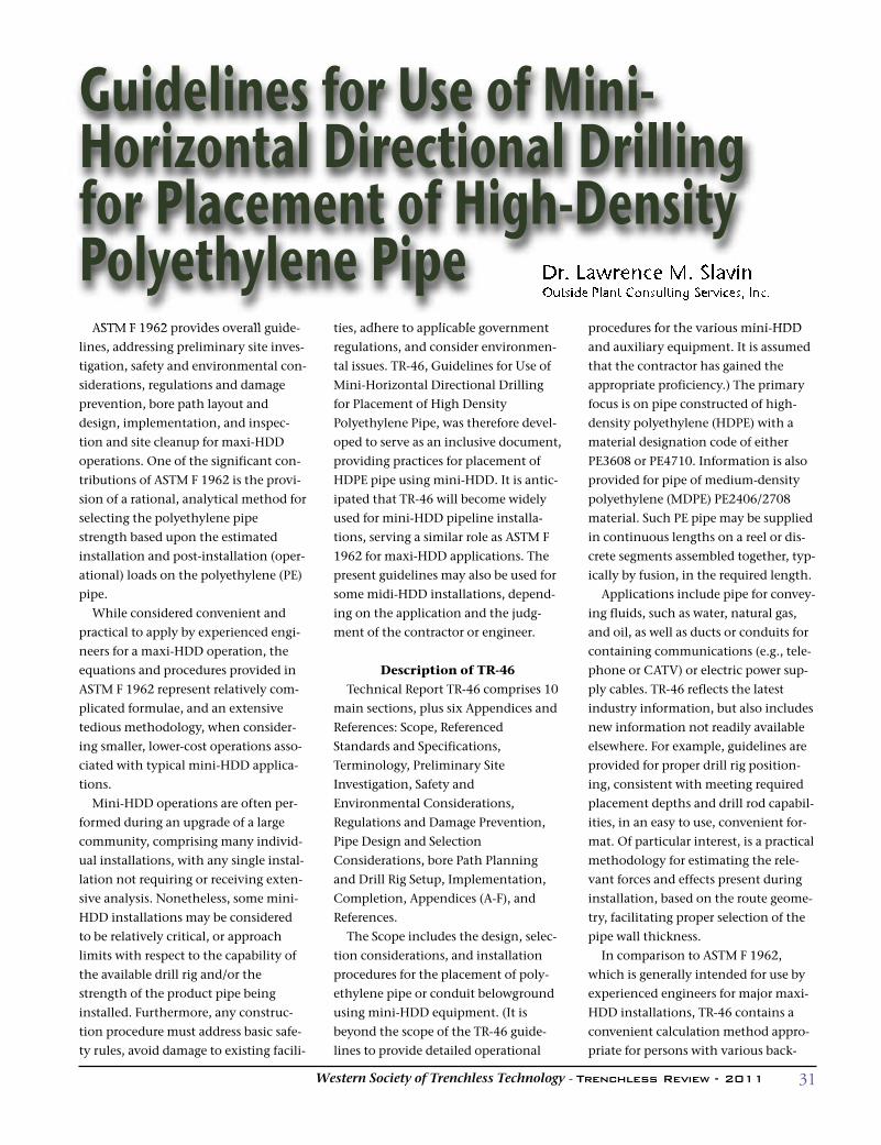
ASTM F 1962 provides overall guide-
lines, addressing preliminary site inves-
tigation, safety and environmental con-
siderations, regulations and damage
prevention, bore path layout and
design, implementation, and inspec-
tion and site cleanup for maxi-HDD
operations. One of the significant con-
tributions of ASTM F 1962 is the provi-
sion of a rational, analytical method for
selecting the polyethylene pipe
strength based upon the estimated
installation and post-installation (oper-
ational) loads on the polyethylene (PE)
pipe.
While considered convenient and
practical to apply by experienced engi-
neers for a maxi-HDD operation, the
equations and procedures provided in
ASTM F 1962 represent relatively com-
plicated formulae, and an extensive
tedious methodology, when consider-
ing smaller, lower-cost operations asso-
ciated with typical mini-HDD applica-
tions.
Mini-HDD operations are often per-
formed during an upgrade of a large
community, comprising many individ-
ual installations, with any single instal-
lation not requiring or receiving exten-
sive analysis. Nonetheless, some mini-
HDD installations may be considered
to be relatively critical, or approach
limits with respect to the capability of
the available drill rig and/or the
strength of the product pipe being
installed. Furthermore, any construc-
tion procedure must address basic safe-
ty rules, avoid damage to existing facili-
ties, adhere to applicable government
regulations, and consider environmen-
tal issues. TR-46, Guidelines for Use of
Mini-Horizontal Directional Drilling
for Placement of High Density
Polyethylene Pipe, was therefore devel-
oped to serve as an inclusive document,
providing practices for placement of
HDPE pipe using mini-HDD. It is antic-
ipated that TR-46 will become widely
used for mini-HDD pipeline installa-
tions, serving a similar role as ASTM F
1962 for maxi-HDD applications. The
present guidelines may also be used for
some midi-HDD installations, depend-
ing on the application and the judg-
ment of the contractor or engineer.
Description of TR-46 Technical Report TR-46 comprises 10
main sections, plus six Appendices and
References: Scope, Referenced
Standards and Specifications,
Terminology, Preliminary Site
Investigation, Safety and
Environmental Considerations,
Regulations and Damage Prevention,
Pipe Design and Selection
Considerations, bore Path Planning
and Drill Rig Setup, Implementation,
Completion, Appendices (A-F), and
References.
The Scope includes the design, selec-
tion considerations, and installation
procedures for the placement of poly-
ethylene pipe or conduit belowground
using mini-HDD equipment. (It is
beyond the scope of the TR-46 guide-
lines to provide detailed operational
procedures for the various mini-HDD
and auxiliary equipment. It is assumed
that the contractor has gained the
appropriate proficiency.) The primary
focus is on pipe constructed of high-
density polyethylene (HDPE) with a
material designation code of either
PE3608 or PE4710. Information is also
provided for pipe of medium-density
polyethylene (MDPE) PE2406/2708
material. Such PE pipe may be supplied
in continuous lengths on a reel or dis-
crete segments assembled together, typ-
ically by fusion, in the required length.
Applications include pipe for convey-
ing fluids, such as water, natural gas,
and oil, as well as ducts or conduits for
containing communications (e.g., tele-
phone or CATV) or electric power sup-
ply cables. TR-46 reflects the latest
industry information, but also includes
new information not readily available
elsewhere. For example, guidelines are
provided for proper drill rig position-
ing, consistent with meeting required
placement depths and drill rod capabil-
ities, in an easy to use, convenient for-
mat. Of particular interest, is a practical
methodology for estimating the rele-
vant forces and effects present during
installation, based on the route geome-
try, facilitating proper selection of the
pipe wall thickness.
In comparison to ASTM F 1962,
which is generally intended for use by
experienced engineers for major maxi-
HDD installations, TR-46 contains a
convenient calculation method appro-
priate for persons with various back-
Dr. Lawrence M. SlavinOutside Plant Consulting Services, Inc.
Guidelines for Use of Mini-Horizontal Directional Drillingfor Placement of High-DensityPolyethylene Pipe
31Western Society of Trenchless Technology - Trenchless Review - 2011
32 Western Society of Trenchless Technology - Trenchless Review - 2011
grounds, including the operators of mini-HDD equipment
and/or the utility engineers. In particular, the procedure pre-
sented provides a means of selecting the pipe strength to
avoid collapse due to hydrostatic pressure at the desired place-
ment depth, as well as to withstand the required pulling loads
during installation. The pipe strength is directly related to the
wall thickness, as specified by its dimension ratio (DR),
defined as the pipe outer diameter by the (minimum) wall
thickness. The methodology is based upon a simplification of
ASTM F 1962.
The guidelines indicate that essentially all the commonly
used wall thicknesses (e.g., DR 7.3 to DR 17) for HDPE pipe
would be sufficiently strong for depths to approximately 15
feet, the typical limit for mini-HDD installations. For depths
greater than 15 feet, thinner wall HDPE, MDPE pipe, or spe-
cial situations, the adequacy of the product for the applica-
tion should be verified using the information in the
Appendix. The allowable depths assume an empty pipe dur-
ing the installation and pre-operational phase, in the absence
of internal fluids or pressure, which would offset the effects of
the external pressure due to drilling fluid/slurry. Although
some HDD installations, such as more complex maxi-HDD
installations, or possibly some midi-HDD applications, may
deliberately allow the pipe to be filled with water or drilling
fluid in order to reduce pull loads due to buoyancy effects, as
well as the net effective hydrostatic pressure, during installa-
tion, such practices are not typically employed in mini-HDD
operations.
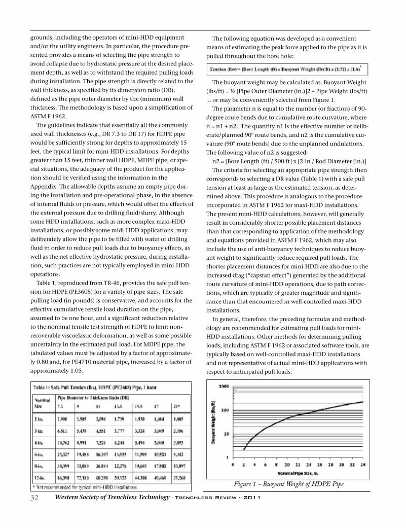
Table 1, reproduced from TR-46, provides the safe pull ten-
sion for HDPE (PE3608) for a variety of pipe sizes. The safe
pulling load (in pounds) is conservative, and accounts for the
effective cumulative tensile load duration on the pipe,
assumed to be one hour, and a significant reduction relative
to the nominal tensile test strength of HDPE to limit non-
recoverable viscoelastic deformation, as well as some possible
uncertainty in the estimated pull load. For MDPE pipe, the
tabulated values must be adjusted by a factor of approximate-
ly 0.80 and, for PE4710 material pipe, increased by a factor of
approximately 1.05.
The following equation was developed as a convenient
means of estimating the peak force applied to the pipe as it is
pulled throughout the bore hole:
The buoyant weight may be calculated as: Buoyant Weight
(lbs/ft) = ½ [Pipe Outer Diameter (in.)]2 – Pipe Weight (lbs/ft)
… or may be conveniently selected from Figure 1.
The parameter n is equal to the number (or fraction) of 90-
degree route bends due to cumulative route curvature, where
n = n1 + n2. The quantity n1 is the effective number of delib-
erate/planned 90° route bends, and n2 is the cumulative cur-
vature (90° route bends) due to the unplanned undulations.
The following value of n2 is suggested:
n2 = [Bore Length (ft) / 500 ft] x [2-in / Rod Diameter (in.)]
The criteria for selecting an appropriate pipe strength then
corresponds to selecting a DR value (Table 1) with a safe pull
tension at least as large as the estimated tension, as deter-
mined above. This procedure is analogous to the procedure
incorporated in ASTM F 1962 for maxi-HDD installations.
The present mini-HDD calculations, however, will generally
result in considerably shorter possible placement distances
than that corresponding to application of the methodology
and equations provided in ASTM F 1962, which may also
include the use of anti-buoyancy techniques to reduce buoy-
ant weight to significantly reduce required pull loads. The
shorter placement distances for mini-HDD are also due to the
increased drag (“capstan effect”) generated by the additional
route curvature of mini-HDD operations, due to path correc-
tions, which are typically of greater magnitude and signifi-
cance than that encountered in well-controlled maxi-HDD
installations.
In general, therefore, the preceding formulas and method-
ology are recommended for estimating pull loads for mini-
HDD installations. Other methods for determining pulling
loads, including ASTM F 1962 or associated software tools, are
typically based on well-controlled maxi-HDD installations
and not representative of actual mini-HDD applications with
respect to anticipated pull loads.
Figure 1 – Buoyant Weight of HDPE Pipe
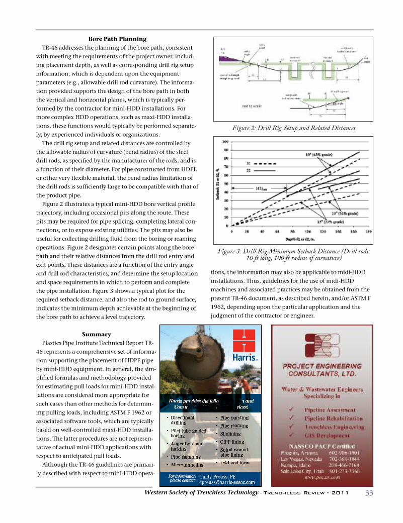
33Western Society of Trenchless Technology - Trenchless Review - 2011
Bore Path PlanningTR-46 addresses the planning of the bore path, consistent
with meeting the requirements of the project owner, includ-
ing placement depth, as well as corresponding drill rig setup
information, which is dependent upon the equipment
parameters (e.g., allowable drill rod curvature). The informa-
tion provided supports the design of the bore path in both
the vertical and horizontal planes, which is typically per-
formed by the contractor for mini-HDD installations. For
more complex HDD operations, such as maxi-HDD installa-
tions, these functions would typically be performed separate-
ly, by experienced individuals or organizations.
The drill rig setup and related distances are controlled by
the allowable radius of curvature (bend radius) of the steel
drill rods, as specified by the manufacturer of the rods, and is
a function of their diameter. For pipe constructed from HDPE
or other very flexible material, the bend radius limitation of
the drill rods is sufficiently large to be compatible with that of
the product pipe.
Figure 2 illustrates a typical mini-HDD bore vertical profile
trajectory, including occasional pits along the route. These
pits may be required for pipe splicing, completing lateral con-
nections, or to expose existing utilities. The pits may also be
useful for collecting drilling fluid from the boring or reaming
operations. Figure 2 designates certain points along the bore
path and their relative distances from the drill rod entry and
exit points. These distances are a function of the entry angle
and drill rod characteristics, and determine the setup location
and space requirements in which to perform and complete
the pipe installation. Figure 3 shows a typical plot for the
required setback distance, and also the rod to ground surface,
indicates the minimum depth achievable at the beginning of
the bore path to achieve a level trajectory.
SummaryPlastics Pipe Institute Technical Report TR-
46 represents a comprehensive set of informa-
tion supporting the placement of HDPE pipe
by mini-HDD equipment. In general, the sim-
plified formulas and methodology provided
for estimating pull loads for mini-HDD instal-
lations are considered more appropriate for
such cases than other methods for determin-
ing pulling loads, including ASTM F 1962 or
associated software tools, which are typically
based on well-controlled maxi-HDD installa-
tions. The latter procedures are not represen-
tative of actual mini-HDD applications with
respect to anticipated pull loads.
Although the TR-46 guidelines are primari-
ly described with respect to mini-HDD opera-
Figure 2: Drill Rig Setup and Related Distances
Figure 3: Drill Rig Minimum Setback Distance (Drill rods:10 ft long, 100 ft radius of curvature)
Harris provides the following Design and Construction Management services:
Cindy Preuss, [email protected]
For information please contact:
:actplease contplease contactmationoror infor inforFFor inf
is-assoc.comreuss@harcpreuss, PECindy Pr
is-assoc.com
tions, the information may also be applicable to midi-HDD
installations. Thus, guidelines for the use of midi-HDD
machines and associated practices may be obtained from the
present TR-46 document, as described herein, and/or ASTM F
1962, depending upon the particular application and the
judgment of the contractor or engineer.
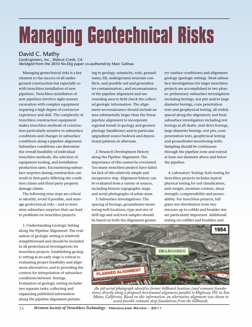
34 Western Society of Trenchless Technology - Trenchless Review - 2011
Managing geotechnical risks is a keyelement to the success of all under-ground construction but especially sowith trenchless installation of newpipelines. Trenchless installation ofnew pipelines involves sight-unseenexcavation with complex equipmentrequiring a high degree of contractorexperience and skill. The complexity oftrenchless construction equipmentmakes trenchless methods of construc-tion particularly sensitive to subsurfaceconditions and changes in subsurfaceconditions along a pipeline alignment.Subsurface conditions can determinethe overall feasibility of individualtrenchless methods, the selection ofequipment tooling, and installationproduction rates. Encountering subsur-face surprises during construction canresult in first-party differing site condi-tion claims and third-party propertydamage claims.The following nine steps are critical
to identify, avoid if possible, and man-age geotechnical risks – and to mini-mize subsurface surprises that can leadto problems on trenchless projects:
1: Understanding Geologic Settingalong the Pipeline Alignment: The eval-uation of geologic setting is relativelystraightforward and should be includedin all geotechnical investigations fortrenchless projects. Establishing geolog-ic setting at an early stage is critical toevaluating project feasibility and align-ment alternatives, and to providing thecontext for interpolation of subsurfaceconditions between borings.Evaluation of geologic setting includestwo separate tasks: collecting andorganizing published informationalong the pipeline alignment pertain-
ing to geology, seismicity, soils, ground-water, fill, underground structure con-flicts, and possible soil and groundwa-ter contamination.; and reconnaissanceof the pipeline alignment and sur-rounding area to field check the collect-ed geologic information. The align-ment reconnaissance should include anarea substantially larger than the linearpipeline alignment to incorporateregional trends in geology and geomor-phology (landforms) and in particularupgradient source bedrock and deposi-tional patterns in alluvium.
2: Research Development Historyalong the Pipeline Alignment: Theimportance of this cannot be overstated.Too many trenchless projects have failedfor lack of this relatively simple andinexpensive step. Alignment history canbe evaluated from a variety of sources,including historic topographic mapsand aerial photographs of urban areas.3: Subsurface Investigations: The
spacing of borings, groundwater-moni-toring well locations, type and size ofdrill rigs and soil/rock samples shouldbe based on both the alignment geome-
try (surface conditions) and alignmentgeology (geologic setting). Most subsur-face investigations for larger trenchlessprojects are accomplished in two phas-es: preliminary subsurface investigationincluding borings, test pits and/or largediameter borings, cone penetrationtests and geophysical testing, all widelyspaced along the alignment; and finalsubsurface investigation including testborings at all shafts, mid-drive borings,large-diameter borings, test pits, conepenetration tests, geophysical testingand groundwater-monitoring wells.Sampling should be continuousthrough the pipeline zone and extendat least one diameter above and belowthe pipeline.
4: Laboratory Testing: Soils testing fortrenchless projects includes typicalphysical testing for soil classification,unit weight, moisture content, shearstrength, compressibility and perme-ability. For trenchless projects, fullgrain size distribution from twomicrons up to cobble and boulder sizeare particularly important. Additionaltesting on cobbles and boulders and
Managing Geotechnical RisksDavid C. MathyGeoEngineers, Inc., Walnut Creek, CAAbridged from the 2010 No-Dig paper co-authored by Marc Gelinas
An old aerial photograph identif ies former billboard locations (and remnant founda-tions) directly along a proposed microtunnel alignment parallel to Highway 101 in SanMateo, California. Based on this information, an alternative alignment was chosen to
avoid possible remnant deep foundations from the billboards.
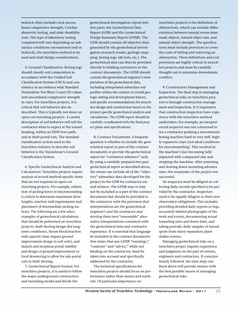
35Western Society of Trenchless Technology - Trenchless Review - 2011
bedrock often includes rock uncon-fined compressive strength, Cercharabrasivity testing, and slake durabilitytests. The type of laboratory testingcompleted will vary depending on sub-surface conditions encountered (soil orbedrock), the trenchless method to beused and shaft design considerations.
5: Ground Classification: Boring logsshould classify soil composition inaccordance with the Unified SoilClassification System (USCS) and con-sistency in accordance with StandardPenetration Test Blow Count (N) valuesand unconfined compressive strengthin clays. For trenchless projects, it iscritical that soil behavior also bedescribed. This is typically not done onopen-cut trenching projects. A carefuldescription of soil behavior will tell thecontractor what to expect at the tunnelheading, within an HDD bore path,and at shaft portal cuts. The standardclassification system used in thetrenchless industry to describe soilbehavior is the Tunnelman’s GroundClassification System.
6: Specific Geotechnical Analysis andCalculations: Trenchless projects requireanalysis of several method-specific itemsthat are not required on open-cuttrenching projects. For example, estima-tion of jacking forces in microtunnelingis critical to determine maximum drivelengths, reaction wall requirements andplacement of intermediate jacking sta-tions. The following are a few selectexamples of geotechnical calculationsthat should be performed on trenchlessprojects: shaft shoring design (for long-term conditions), thrust block/reactionwall capacity (may require groundimprovement design in soft soils), andlaunch and reception portal stabilityand design of ground improvement orlocal dewatering to allow for safe portalcuts in shaft shoring.7: Geotechnical Report Format: For
trenchless projects, it is useful to followthe major underground constructionand tunneling model and divide the
geotechnical investigation report intotwo parts: the Geotechnical DataReport (GDR) and the GeotechnicalDesign Summary Report (GDSR). TheGDR should contain all objective datagenerated by the geotechnical investi-gation (research results, geologic map-ping, boring logs, lab tests, etc.). Thegeotechnical data can then be provideddirectly to bidding contractors in thecontract documents. The GDSR shouldcontain the geotechnical engineer’s inter-pretation of the geotechnical data,including interpolated subsurface soilprofiles within the context of overall geo-logic setting and development history,and specific recommendations for trench-less design and construction based on theproject-specific geotechnical analysis andcalculations. The GDSR report should becarefully coordinated with the final proj-ect plans and specifications.
8: Contract Documents: A frequentquestion is whether to include the geot-echnical report as part of the contractdocuments or provide the geotechnicalreport for “contractor reference” only.By using a carefully prepared two-partgeotechnical report as described above,the owner can include all of the “objec-tive” subsurface data developed for theproject in the GDR for contractor useand reliance. The GDSR may or maynot be included as a part of the contractdocuments but should be provided tothe contractor with the provision thatinterpretations are the geotechnicalengineer’s and the contractor maydevelop their own “reasonable” alter-native interpretations consistent withthe geotechnical data and contractorexperience. It is essential that languagebe included in the contract documentsthat states that any GDSR “warnings,”“cautions” and “advice,” while notbinding on the contractor, must betaken into account and specificallyaddressed by the contractor.The technical specifications for
trenchless projects should focus on per-formance rather than means and meth-ods. Of particular importance on
trenchless projects is the definition ofobstructions, which can include differ-entiation between natural versus man-made objects, natural object size, andnatural object strength. The specifica-tions must include provisions to coverthe costs of hitting and removing anobstruction. These definitions and costprovisions are highly critical in trench-less projects and must be carefullythought out to minimize downstreamconflicts.
9: Construction Management andInspection: The final step in managinggeotechnical risks on trenchless proj-ects is through construction manage-ment and inspection. It is imperativethat construction inspectors have expe-rience with the trenchless methodundertaken. For example, an inexperi-enced inspector was not concerned tosee a contractor pushing a microtunnel-boring machine hard in very stiff, high-ly expansive clays (not ideal conditionsfor microtunneling). This resulted inthe machine’s face becoming fullyimpacted with compacted clay andstopping the machine. After restartingand slowing down tunneling advancerates, the remainder of the project wassuccessful.An inspector must be diligent in col-
lecting daily records specified to be pro-vided by the contractor. Inspectorsneed to be equally diligent in their ownobservation obligations. This includesproviding detailed daily reports or logs,accurately labeled photographs of thework and events, documenting actualtunneling rates and down time, andtaking periodic daily samples of tunnelspoils from slurry separation plantshaker screens.Managing geotechnical risks on a
trenchless project requires experienceand judgment on the part of owners,engineers and contractors. If conscien-tiously followed, the nine steps out-lined above will provide owners withthe best possible means of managinggeotechnical risks.
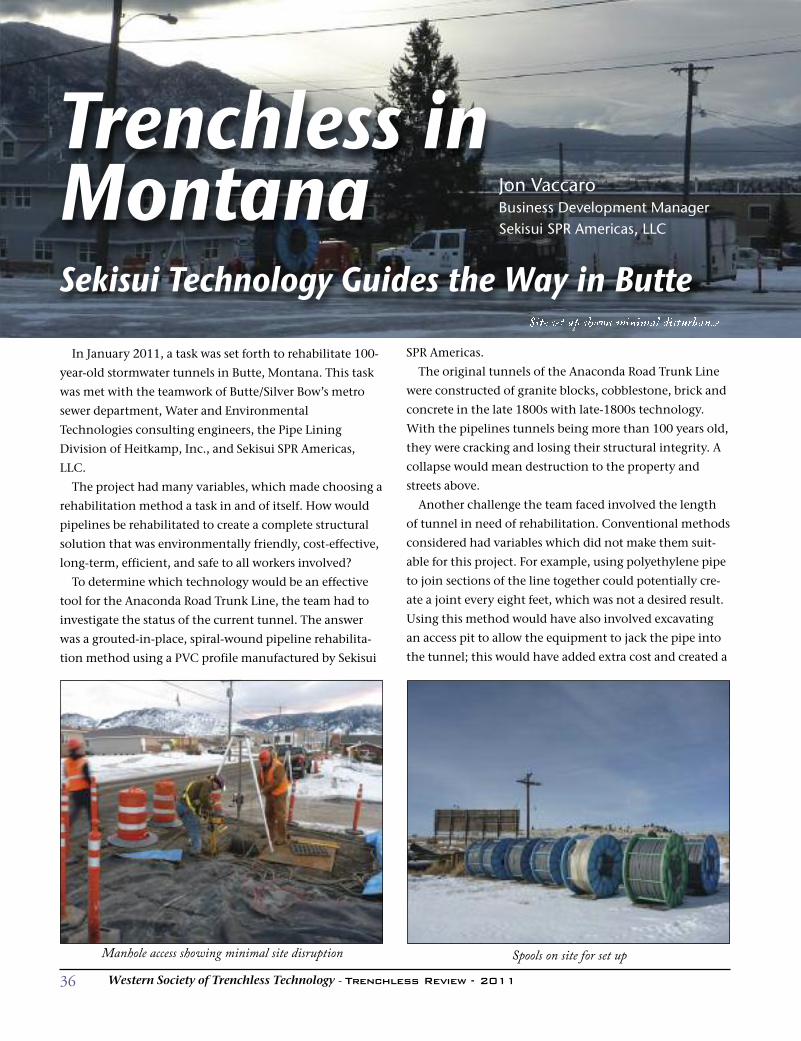
36 Western Society of Trenchless Technology - Trenchless Review - 2011
SPR Americas.
The original tunnels of the Anaconda Road Trunk Line
were constructed of granite blocks, cobblestone, brick and
concrete in the late 1800s with late-1800s technology.
With the pipelines tunnels being more than 100 years old,
they were cracking and losing their structural integrity. A
collapse would mean destruction to the property and
streets above.
Another challenge the team faced involved the length
of tunnel in need of rehabilitation. Conventional methods
considered had variables which did not make them suit-
able for this project. For example, using polyethylene pipe
to join sections of the line together could potentially cre-
ate a joint every eight feet, which was not a desired result.
Using this method would have also involved excavating
an access pit to allow the equipment to jack the pipe into
the tunnel; this would have added extra cost and created a
Site set up shows minimal disturbance
Trenchless inMontanaSekisui Technology Guides the Way in Butte
Jon VaccaroBusiness Development ManagerSekisui SPR Americas, LLC
In January 2011, a task was set forth to rehabilitate 100-
year-old stormwater tunnels in Butte, Montana. This task
was met with the teamwork of Butte/Silver Bow’s metro
sewer department, Water and Environmental
Technologies consulting engineers, the Pipe Lining
Division of Heitkamp, Inc., and Sekisui SPR Americas,
LLC.
The project had many variables, which made choosing a
rehabilitation method a task in and of itself. How would
pipelines be rehabilitated to create a complete structural
solution that was environmentally friendly, cost-effective,
long-term, efficient, and safe to all workers involved?
To determine which technology would be an effective
tool for the Anaconda Road Trunk Line, the team had to
investigate the status of the current tunnel. The answer
was a grouted-in-place, spiral-wound pipeline rehabilita-
tion method using a PVC profile manufactured by Sekisui
Manhole access showing minimal site disruption Spools on site for set up
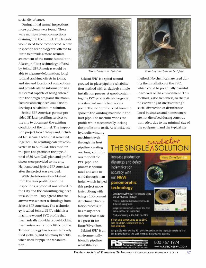
37Western Society of Trenchless Technology - Trenchless Review - 2011
method. No chemicals are used dur-
ing the installation of the PVC,
which could be potentially harmful
to workers or the environment. This
method is also trenchless, so there is
no excavating of streets causing a
social distraction or disturbance.
Local businesses and homeowners
are not disturbed during construc-
tion. Also, due to the minimal size of
the equipment and the typical site
social disturbance.
During initial tunnel inspections,
more problems were found. There
were multiple lateral connections
draining into the tunnel. The laterals
would need to be reconnected. A new
inspection technology was offered to
Butte to provide a more accurate
assessment of the tunnel’s condition.
A laser profiling technology offered
by Sekisui SPR Americas would be
able to measure deformation, longi-
tudinal cracking, offsets in joints,
and size and location of connections,
and provide all the information in a
3D format capable of being entered
into the design programs the manu-
facturer and engineer would use to
develop a rehabilitation solution.
Sekisui SPR Americas partner pro-
vided 3D laser profiling services to
the city to document the existing
condition of the tunnel. The inspec-
tion project took 10 days and includ-
ed 161 separate scans that were tied
together. The resulting data was con-
verted in to AutoCAD files to show
the plan and profile of the pipe. A
total of 36 AutoCAD plan and profile
sheets were provided to the city,
Heitkamp and Sekisui SPR Americas
after the project was awarded.
With the information obtained
from the laser profiling and the
inspections, a proposal was offered to
the City and the consulting engineer
for a solution. They agreed that the
answer was a newer technology from
Sekisui SPR Americas. The technolo-
gy is called Sekisui SPR™, which is a
machine-wound PVC profile that
mechanically provides a duel-locking
mechanism on its monolithic profile.
This technology has been extensively
used globally, and has many benefits
when used for pipeline rehabilita-
tion.
Sekisui SPR™ is a spiral-wound
grouted-in-place pipeline rehabilita-
tion method with a relatively simple
installation process. A spool contain-
ing the PVC profile sits above grade
at a standard manhole or access
point. The PVC profile is fed from the
spool to the winding machine in the
host pipe. The machine winds the
profile while mechanically locking
the profile onto itself. As it locks, the
hydraulic winding
machine travels
through the host
pipeline, creating
one long, continu-
ous monolithic
PVC pipe. The
process is seismic-
rated and able to
wind through man-
holes, which helped
this project move
faster. Along with
being a 100-percent
structural rehabili-
tation process, it
has many other
benefits that made
it a great fit for
Butte/Silver Bow.
Sekisui SPR™ is an
environmentally
friendly pipeline
rehabilitation
Tunnel before installation Winding machine in host pipe
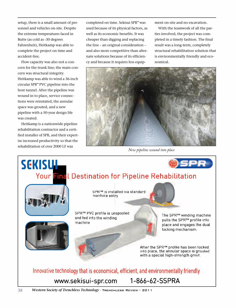
38 Western Society of Trenchless Technology - Trenchless Review - 2011
ment on-site and no excavation.
With the teamwork of all the par-
ties involved, the project was com-
pleted in a timely fashion. The final
result was a long-term, completely
structural rehabilitation solution that
is environmentally friendly and eco-
nomical.
setup, there is a small amount of per-
sonnel and vehicles on-site. Despite
the extreme temperatures faced in
Butte (as cold as -30 degrees
Fahrenheit), Heitkamp was able to
complete the project on time and
accident-free.
Flow capacity was also not a con-
cern for the trunk line; the main con-
cern was structural integrity.
Heitkamp was able to wind a 36-inch
circular SPR™ PVC pipeline into the
host tunnel. After the pipeline was
wound in to place, service connec-
tions were reinstated, the annular
space was grouted, and a new
pipeline with a 50-year design life
was created.
Heitkamp is a nationwide pipeline
rehabilitation contractor and a certi-
fied installer of SPR, and their expert-
ise increased productivity so that the
rehabilitation of over 2000 LF was
completed on time. Sekisui SPR™ was
used because of its physical factors, as
well as its economic benefits. It was
cheaper than digging and replacing
the line – an original consideration –
and also more competitive than alter-
nate solutions because of its efficien-
cy and because it requires less equip-
New pipeline wound into place
Your Final Destination for Pipeline Rehabilitation
1-866-62-SSPRAwww.sekisui-spr.comInnovative technology that is economical, efficient, and environmentally friendly
SPR™ is installed via standard manhole entry
After the SPR™ profile has been locked into place, the annular space is grouted with a special high-strength grout.
The SPR™ winding machine pulls the SPR™ profile into place and engages the dual locking mechanism.
SPR™ PVC profile is unspooled and fed into the winding machine
Your Final Destination for Pipeline Rehabilitation
wwwativovInn e t
w.sekisui-spr..r com
1-866-62-Som
SPRA
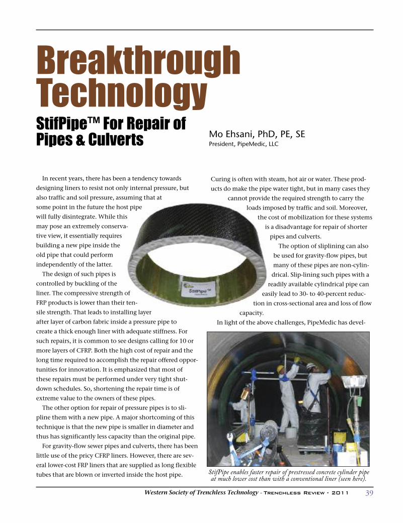
39Western Society of Trenchless Technology - Trenchless Review - 2011
In recent years, there has been a tendency towards
designing liners to resist not only internal pressure, but
also traffic and soil pressure, assuming that at
some point in the future the host pipe
will fully disintegrate. While this
may pose an extremely conserva-
tive view, it essentially requires
building a new pipe inside the
old pipe that could perform
independently of the latter.
The design of such pipes is
controlled by buckling of the
liner. The compressive strength of
FRP products is lower than their ten-
sile strength. That leads to installing layer
after layer of carbon fabric inside a pressure pipe to
create a thick enough liner with adequate stiffness. For
such repairs, it is common to see designs calling for 10 or
more layers of CFRP. Both the high cost of repair and the
long time required to accomplish the repair offered oppor-
tunities for innovation. It is emphasized that most of
these repairs must be performed under very tight shut-
down schedules. So, shortening the repair time is of
extreme value to the owners of these pipes.
The other option for repair of pressure pipes is to sli-
pline them with a new pipe. A major shortcoming of this
technique is that the new pipe is smaller in diameter and
thus has significantly less capacity than the original pipe.
For gravity-flow sewer pipes and culverts, there has been
little use of the pricy CFRP liners. However, there are sev-
eral lower-cost FRP liners that are supplied as long flexible
tubes that are blown or inverted inside the host pipe.
Curing is often with steam, hot air or water. These prod-
ucts do make the pipe water tight, but in many cases they
cannot provide the required strength to carry the
loads imposed by traffic and soil. Moreover,
the cost of mobilization for these systems
is a disadvantage for repair of shorter
pipes and culverts.
The option of sliplining can also
be used for gravity-flow pipes, but
many of these pipes are non-cylin-
drical. Slip-lining such pipes with a
readily available cylindrical pipe can
easily lead to 30- to 40-percent reduc-
tion in cross-sectional area and loss of flow
capacity.
In light of the above challenges, PipeMedic has devel-
BreakthroughTechnologyStifPipe™ For Repair of Pipes & culverts
Mo Ehsani, PhD, PE, SEPresident, PipeMedic, LLC
StifPipe enables faster repair of prestressed concrete cylinder pipeat much lower cost than with a conventional liner (seen here).

40 Western Society of Trenchless Technology - Trenchless Review - 2011
oped the patent-pending StifPipe™ that takes advantage of
honeycomb technology. Honeycomb construction was
originally developed by the aerospace industry to achieve
strong and lightweight structures. It has also been success-
fully used in construction of boats, so exposure to water is
not a concern. A layer of FRP is used as skin reinforcement
that is applied to both faces of a lightweight honeycomb
core. The principles of design are simple: By separating the
outer skin layers with a honeycomb core, one can achieve
high stiffness at a fraction of the cost of a solid cross-sec-
tion.
Manufacturing can be done onsite or offsite. A mandrel
is prepared as a template and the required number of lay-
ers of saturated fabric and honeycomb core are applied
successively to create a pipe of desired shape, size and
strength. Finished sections of StifPipe™ can be tested to
verify that they meet the project specifications (see Test
Box).
Development and Advantages
In the late 1980s, researchers at the University of
Arizona were the first to introduce the concept of repair
and retrofit of bridges and buildings with FRP to the con-
struction industry (1). Fiber Reinforced Polymer (FRP) is
made of fabrics of carbon or glass that are saturated with
epoxy resins. In a process known as wet layup, the fabric is
saturated with resin in the field and is bonded to the exte-
rior surface of beam or column; upon curing in several
hours, it becomes 2-3 times stronger than steel! The high
tensile strength, light weight, durability and ease of instal-
lation have made these products very popular in repair
and retrofit projects.
The use of wet layup carbon FRP to
strengthen Prestressed Concrete
Cylinder Pipe (PCCP) began in the late
1990s. As shown in Fig. 1, these pipes
consist of a steel cylinder that is sand-
wiched between layers of concrete and
wrapped on the outside with prestressed
wires. PCCPs have been used extensive-
ly worldwide as water transmission
lines. Improper design and poor con-
struction practices have resulted in
breaking of the stressed wires and cata-
strophic failure of many of the older
pipes. As seen on many news stories,
once the pipe fails large volumes of
water under high pressure can create
rivers running down streets and city blocks in seconds.
Wet layup carbon FRP (CFRP) is a cost-effective method
to retrofit the weak segments of a PCCP prior to failure. In
this trenchless repair technique, the crew can enter the
pipe through access ports and apply carbon fabric to the
interior surface of the pipe. Once the fabric cures, it cre-
ates a pressure vessel that can relieve the PCCP from carry-
ing all or part of the internal pressure. This technique is
fairly well accepted and recognized by the industry, and
PipeMedic has been an award-winning (2) leader in this
field with work that includes the world’s largest pipeline
repair project using FRP (1.1 mile of an 84-inch pipe) (3).
Because the tensile strength of CFRP is 2-3 times that of
steel, the application of a small number (typically 2-4) of
layers of carbon fabric is sufficient to restore the integrity
of the pipe. This makes the technique cost-competitive,
especially in cases where digging and replacement of the
pipe is not easy. But when the liner is expected to carry
internal and external loads, the use of CFRP leads to many
layers of carbon that make the projects too expensive and
time-consuming. It was the combination of these prob-
lems and 25 years of R&D that led to the development of
StifPipe™.
StifPipe™ has some unique and advantageous attributes,
not least of which is that it can be manufactured to any
size. Unlike conventional pipes, it is not limited to avail-
able “round” pipe diameter sizes only. For example, it is
possible to line a 60-inch-diameter pipe with a StifPipe™
having an outside diameter of 59.5 inches, thereby maxi-
mizing the flow capacity.
8 0 0 . 5 3 3 . 0 3 8 6 | a k k @ a k k e r m a n . c o m | w w w . a k k e r m a n . c o m
Since 1973, Akkerman Inc. has manufactured distinctive microtunneling, pipejacking, tunneling, guided boring and earth pressure balance equipment for tunnels up to 14’ in diameter. We are proud to be the only North American manufacturer of our variety of equipment and a recognized worldwide competitor. Our equipment, like our company, is built to last. We’ll be here to assist you and provide innovative solutions every step of the way.
Since 1973, Akkerman Inc. has manufactured distinctive microtunneling, pipejacking, tunneling, guidedboring and earth pressure balance equipment for tunnels up to 14’ in diameter. We are proud to be the only
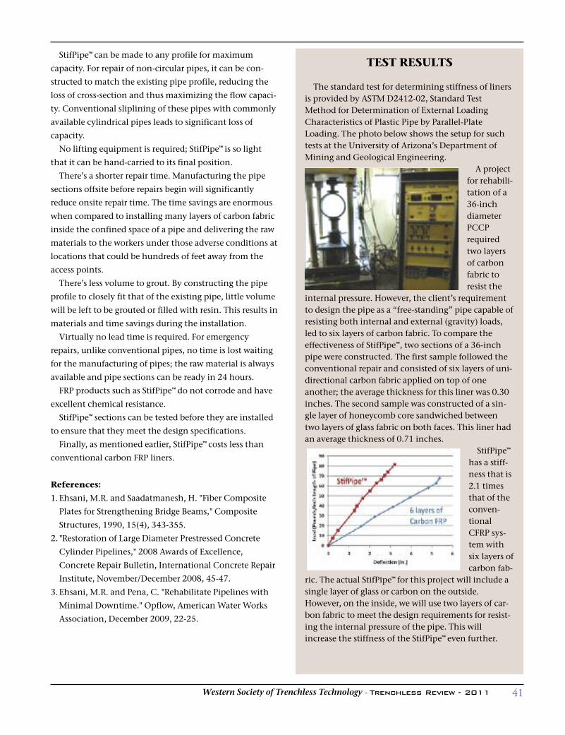
41Western Society of Trenchless Technology - Trenchless Review - 2011
StifPipe™ can be made to any profile for maximum
capacity. For repair of non-circular pipes, it can be con-
structed to match the existing pipe profile, reducing the
loss of cross-section and thus maximizing the flow capaci-
ty. Conventional sliplining of these pipes with commonly
available cylindrical pipes leads to significant loss of
capacity.
No lifting equipment is required; StifPipe™ is so light
that it can be hand-carried to its final position.
There’s a shorter repair time. Manufacturing the pipe
sections offsite before repairs begin will significantly
reduce onsite repair time. The time savings are enormous
when compared to installing many layers of carbon fabric
inside the confined space of a pipe and delivering the raw
materials to the workers under those adverse conditions at
locations that could be hundreds of feet away from the
access points.
There’s less volume to grout. By constructing the pipe
profile to closely fit that of the existing pipe, little volume
will be left to be grouted or filled with resin. This results in
materials and time savings during the installation.
Virtually no lead time is required. For emergency
repairs, unlike conventional pipes, no time is lost waiting
for the manufacturing of pipes; the raw material is always
available and pipe sections can be ready in 24 hours.
FRP products such as StifPipe™ do not corrode and have
excellent chemical resistance.
StifPipe™ sections can be tested before they are installed
to ensure that they meet the design specifications.
Finally, as mentioned earlier, StifPipe™ costs less than
conventional carbon FRP liners.
References:
1.Ehsani, M.R. and Saadatmanesh, H. "Fiber Composite
Plates for Strengthening Bridge Beams," Composite
Structures, 1990, 15(4), 343-355.
2. "Restoration of Large Diameter Prestressed Concrete
Cylinder Pipelines," 2008 Awards of Excellence,
Concrete Repair Bulletin, International Concrete Repair
Institute, November/December 2008, 45-47.
3.Ehsani, M.R. and Pena, C. "Rehabilitate Pipelines with
Minimal Downtime." Opflow, American Water Works
Association, December 2009, 22-25.
TEST RESULTS
The standard test for determining stiffness of linersis provided by ASTM D2412-02, Standard TestMethod for Determination of External LoadingCharacteristics of Plastic Pipe by Parallel-PlateLoading. The photo below shows the setup for suchtests at the University of Arizona’s Department ofMining and Geological Engineering.
A projectfor rehabili-tation of a36-inchdiameterPCCPrequiredtwo layersof carbonfabric toresist the
internal pressure. However, the client’s requirementto design the pipe as a “free-standing” pipe capable ofresisting both internal and external (gravity) loads,led to six layers of carbon fabric. To compare theeffectiveness of StifPipe™, two sections of a 36-inchpipe were constructed. The first sample followed theconventional repair and consisted of six layers of uni-directional carbon fabric applied on top of oneanother; the average thickness for this liner was 0.30inches. The second sample was constructed of a sin-gle layer of honeycomb core sandwiched betweentwo layers of glass fabric on both faces. This liner hadan average thickness of 0.71 inches.
StifPipe™has a stiff-ness that is2.1 timesthat of theconven-tionalCFRP sys-tem withsix layers ofcarbon fab-
ric. The actual StifPipe™ for this project will include asingle layer of glass or carbon on the outside.However, on the inside, we will use two layers of car-bon fabric to meet the design requirements for resist-ing the internal pressure of the pipe. This willincrease the stiffness of the StifPipe™ even further.
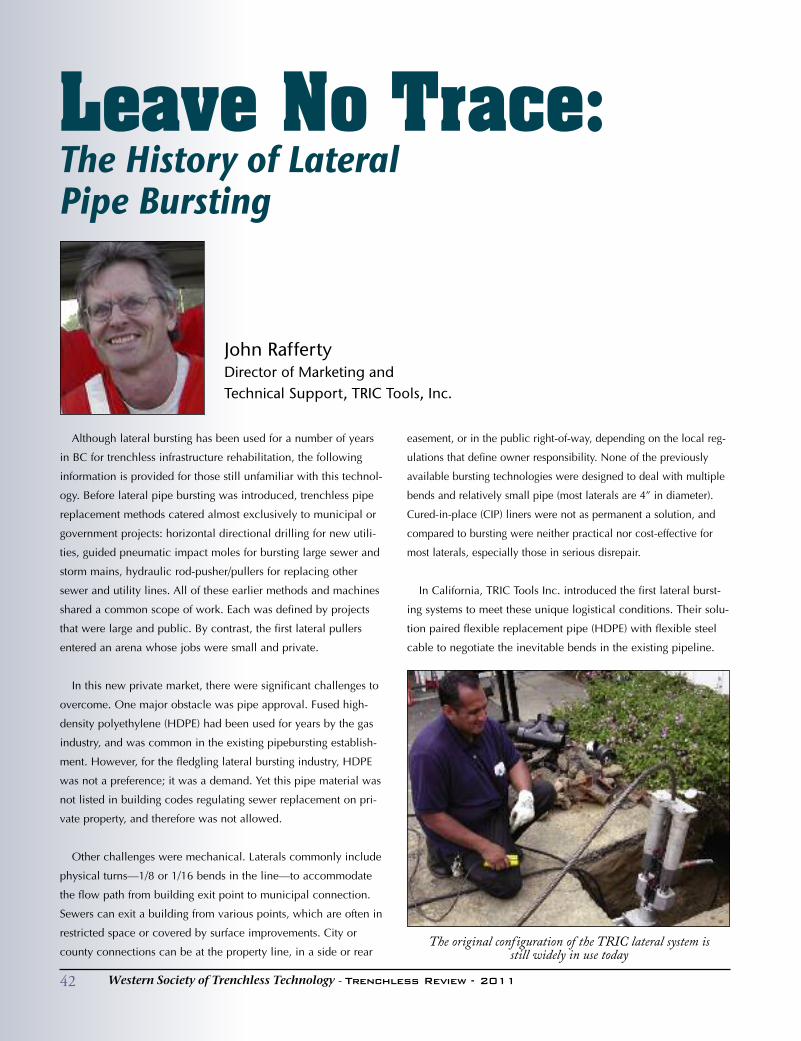
Leave No Trace: The History of Lateral Pipe Bursting
John RaffertyDirector of Marketing andTechnical Support, TRIC Tools, Inc.
Although lateral bursting has been used for a number of years
in BC for trenchless infrastructure rehabilitation, the following
information is provided for those still unfamiliar with this technol-
ogy. Before lateral pipe bursting was introduced, trenchless pipe
replacement methods catered almost exclusively to municipal or
government projects: horizontal directional drilling for new utili-
ties, guided pneumatic impact moles for bursting large sewer and
storm mains, hydraulic rod-pusher/pullers for replacing other
sewer and utility lines. All of these earlier methods and machines
shared a common scope of work. Each was defined by projects
that were large and public. By contrast, the first lateral pullers
entered an arena whose jobs were small and private.
In this new private market, there were significant challenges to
overcome. One major obstacle was pipe approval. Fused high-
density polyethylene (HDPE) had been used for years by the gas
industry, and was common in the existing pipebursting establish-
ment. However, for the fledgling lateral bursting industry, HDPE
was not a preference; it was a demand. Yet this pipe material was
not listed in building codes regulating sewer replacement on pri-
vate property, and therefore was not allowed.
Other challenges were mechanical. Laterals commonly include
physical turns—1/8 or 1/16 bends in the line—to accommodate
the flow path from building exit point to municipal connection.
Sewers can exit a building from various points, which are often in
restricted space or covered by surface improvements. City or
county connections can be at the property line, in a side or rear
easement, or in the public right-of-way, depending on the local reg-
ulations that define owner responsibility. None of the previously
available bursting technologies were designed to deal with multiple
bends and relatively small pipe (most laterals are 4” in diameter).
Cured-in-place (CIP) liners were not as permanent a solution, and
compared to bursting were neither practical nor cost-effective for
most laterals, especially those in serious disrepair.
In California, TRIC Tools Inc. introduced the first lateral burst-
ing systems to meet these unique logistical conditions. Their solu-
tion paired flexible replacement pipe (HDPE) with flexible steel
cable to negotiate the inevitable bends in the existing pipeline.
The original configuration of the TRIC lateral system is still widely in use today
42 Western Society of Trenchless Technology - Trenchless Review - 2011
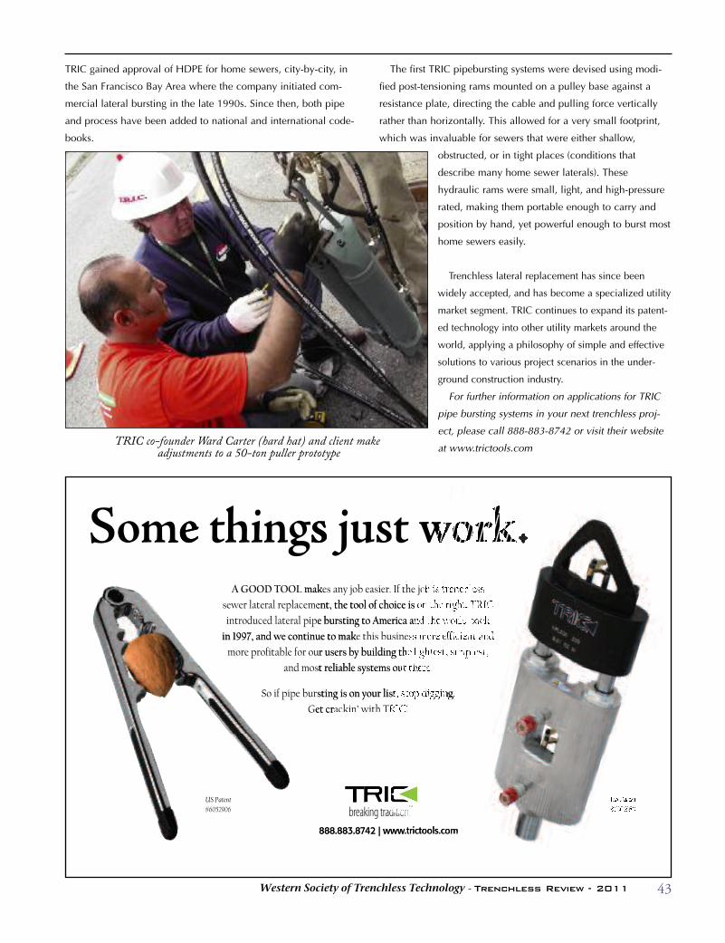
43Western Society of Trenchless Technology - Trenchless Review - 2011
TRIC gained approval of HDPE for home sewers, city-by-city, in
the San Francisco Bay Area where the company initiated com-
mercial lateral bursting in the late 1990s. Since then, both pipe
and process have been added to national and international code-
books.
The first TRIC pipebursting systems were devised using modi-
fied post-tensioning rams mounted on a pulley base against a
resistance plate, directing the cable and pulling force vertically
rather than horizontally. This allowed for a very small footprint,
which was invaluable for sewers that were either shallow,
obstructed, or in tight places (conditions that
describe many home sewer laterals). These
hydraulic rams were small, light, and high-pressure
rated, making them portable enough to carry and
position by hand, yet powerful enough to burst most
home sewers easily.
Trenchless lateral replacement has since been
widely accepted, and has become a specialized utility
market segment. TRIC continues to expand its patent-
ed technology into other utility markets around the
world, applying a philosophy of simple and effective
solutions to various project scenarios in the under-
ground construction industry.
For further information on applications for TRIC
pipe bursting systems in your next trenchless proj-
ect, please call 888-883-8742 or visit their website
at www.trictools.comTRIC co-founder Ward Carter (hard hat) and client make
adjustments to a 50-ton puller prototype
888.883.8742 | www.trictools.com
eomS
sgnih te makA GOOD TOOL
wstu jses any job easier. If the job is trenchless mak
et crG
So if pipe bursting is on your list, stop digging.
and most reliable systems out there.
more profitable for our users by building the lightest, simplest,
in 1997, and we continue to mak
al pipe bursting to America and the world back introduced later
al replacement, the tool of choice is on the right. TRIC sewer later
ackin’ with TRIC!et cr
So if pipe bursting is on your list, stop digging.
and most reliable systems out there.
more profitable for our users by building the lightest, simplest,
e this business more efficient and in 1997, and we continue to mak
al pipe bursting to America and the world back
al replacement, the tool of choice is on the right. TRIC
#6052906US Patent
.trictools.com42 | www7888.883.8
.trictools.com

44 Western Society of Trenchless Technology - Trenchless Review - 2011
Vitrified Clay Pipe (VCP) has become the material of
choice for some trenchless installation processes for many
reasons, but the most commonly cited are strength, abra-
sion resistance and lifecycle. VCP is uniquely suited to
pilot tube microtunneling (PTMT), slurry microtunneling
and static pipe bursting. Recently, in addition to the func-
tional benefits of VCP, The Institute for Market
Transformation to Sustainability (MTS) has certified the
pipe material as an environmentally responsible choice.
Pilot Tube and Slurry MicrotunnelingVitrified Clay Jacking Pipe has been the predominant
direct-jacked product pipe material used in the eight-inch
thru 36-inch size range. Clay pipe, in the typical one- or
two-meter lengths, is ideally suited for use with compact
jacking frames and the small shaft sizes of pilot tube and
slurry microtunneling installations. Tunnel equipment
tooling is often sized to match the outside diameter and
pipe lengths of VCP. Clay pipe has an average compressive
strength of 18,000 psi to stand up to the considerable jack-
ing force of installation. The vitrified nature of the pipe
also provides the needed abrasion resistance to prevent
external damage as the pipe is pushed or pulled through
the surrounding ground. In these installation processes,
the greatest load the pipe will ever encounter is the axial
force incurred during installation.
With the accuracy of a guided tunneling system, such as
pilot tube or slurry microtunneling, there is no need for a
larger diameter steel casing and the grade-adjusted inner
carrier pipe. A larger diameter steel casing is required for a
non-guided boring installation technique when installing
a gravity flow line with a slope less than 3%. Eliminating
this casing pipe saves the additional cost of excavation,
transportation, and disposal of spoil as well as the pur-
chase of two separate conduits, thus resulting in a lower
overall project cost.
The longest slurry microtunneling drive on record with
the National Clay Pipe Institute was a single drive of 892
An 18-inch pipe is loaded into the pit for a pilot tube microtunneling project in Honolulu, Hawaii.
Vitrified clayJacking Pipeand TrenchlessinstallationMethodsJeff Boschert, P.E.National Clay Pipe Institute
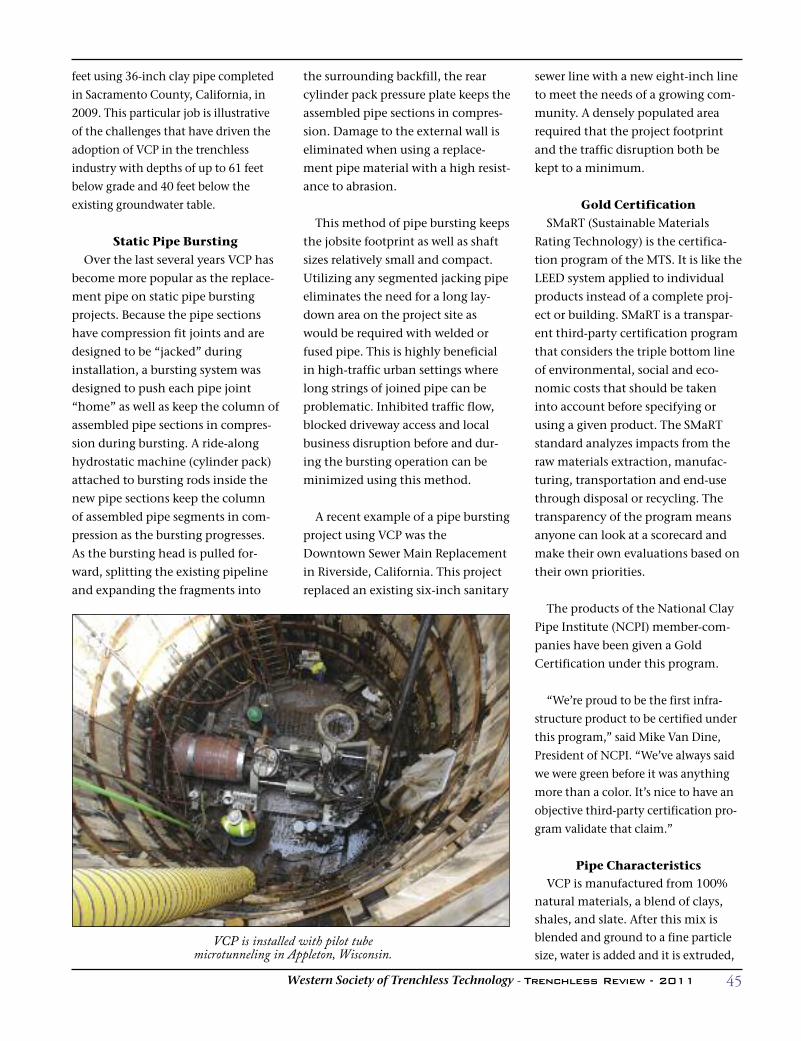
45Western Society of Trenchless Technology - Trenchless Review - 2011
feet using 36-inch clay pipe completed
in Sacramento County, California, in
2009. This particular job is illustrative
of the challenges that have driven the
adoption of VCP in the trenchless
industry with depths of up to 61 feet
below grade and 40 feet below the
existing groundwater table.
Static Pipe BurstingOver the last several years VCP has
become more popular as the replace-
ment pipe on static pipe bursting
projects. Because the pipe sections
have compression fit joints and are
designed to be “jacked” during
installation, a bursting system was
designed to push each pipe joint
“home” as well as keep the column of
assembled pipe sections in compres-
sion during bursting. A ride-along
hydrostatic machine (cylinder pack)
attached to bursting rods inside the
new pipe sections keep the column
of assembled pipe segments in com-
pression as the bursting progresses.
As the bursting head is pulled for-
ward, splitting the existing pipeline
and expanding the fragments into
the surrounding backfill, the rear
cylinder pack pressure plate keeps the
assembled pipe sections in compres-
sion. Damage to the external wall is
eliminated when using a replace-
ment pipe material with a high resist-
ance to abrasion.
This method of pipe bursting keeps
the jobsite footprint as well as shaft
sizes relatively small and compact.
Utilizing any segmented jacking pipe
eliminates the need for a long lay-
down area on the project site as
would be required with welded or
fused pipe. This is highly beneficial
in high-traffic urban settings where
long strings of joined pipe can be
problematic. Inhibited traffic flow,
blocked driveway access and local
business disruption before and dur-
ing the bursting operation can be
minimized using this method.
A recent example of a pipe bursting
project using VCP was the
Downtown Sewer Main Replacement
in Riverside, California. This project
replaced an existing six-inch sanitary
sewer line with a new eight-inch line
to meet the needs of a growing com-
munity. A densely populated area
required that the project footprint
and the traffic disruption both be
kept to a minimum.
Gold CertificationSMaRT (Sustainable Materials
Rating Technology) is the certifica-
tion program of the MTS. It is like the
LEED system applied to individual
products instead of a complete proj-
ect or building. SMaRT is a transpar-
ent third-party certification program
that considers the triple bottom line
of environmental, social and eco-
nomic costs that should be taken
into account before specifying or
using a given product. The SMaRT
standard analyzes impacts from the
raw materials extraction, manufac-
turing, transportation and end-use
through disposal or recycling. The
transparency of the program means
anyone can look at a scorecard and
make their own evaluations based on
their own priorities.
The products of the National Clay
Pipe Institute (NCPI) member-com-
panies have been given a Gold
Certification under this program.
“We’re proud to be the first infra-
structure product to be certified under
this program,” said Mike Van Dine,
President of NCPI. “We’ve always said
we were green before it was anything
more than a color. It’s nice to have an
objective third-party certification pro-
gram validate that claim.”
Pipe CharacteristicsVCP is manufactured from 100%
natural materials, a blend of clays,shales, and slate. After this mix isblended and ground to a fine particlesize, water is added and it is extruded,
VCP is installed with pilot tube microtunneling in Appleton, Wisconsin.
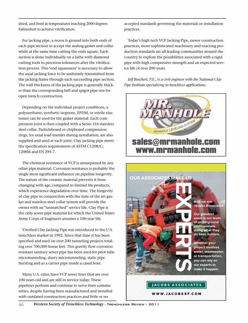
46 Western Society of Trenchless Technology - Trenchless Review - 2011
dried, and fired at temperatures reaching 2000 degreesFahrenheit to achieve vitrification.
For jacking pipe, a recess is ground into both ends ofeach pipe section to accept the sealing gasket and collarwhile at the same time cutting the ends square. Eachsection is done individually on a lathe with diamondcutting tools to precision tolerances after the vitrifica-tion process. This ‘end squareness’ is necessary to allowthe axial jacking force to be uniformly transmitted fromthe jacking frame through each succeeding pipe section.The wall thickness of the jacking pipe is generally thick-er than the corresponding bell and spigot pipe size foropen trench construction.
Depending on the individual project conditions, apolyurethane, synthetic isoprene, EPDM, or nitrile elas-tomer can be used for the gasket material. Each com-pression joint is then coupled with a Series 316 stainlesssteel collar. Particleboard or chipboard compressionrings, for axial load transfer during installation, are alsosupplied and used at each joint. Clay jacking pipe meetsthe specification requirements of ASTM C1208/C;1208M and EN 295-7.
The chemical resistance of VCP is unsurpassed by anyother pipe material. Corrosion resistance is probably thesingle most significant influence on pipeline longevity.The nature of the ceramic material prevents it fromchanging with age, compared to limited life products,which experience degradation over time. The longevityof clay pipe in conjunction with the state of the art gas-ket and stainless steel collar system will provide theowner with an “unmatched” service life. Clay Pipe isthe only sewer pipe material for which the United StatesArmy Corps of Engineers assumes a 100-year life.
Vitrified Clay Jacking Pipe was introduced to the U.S.trenchless market in 1992. Since that time it has beenspecified and used on over 200 tunneling projects total-ing over 700,000 linear feet. This gravity flow corrosionresistant sanitary sewer pipe has been used for pilot tubemicrotunneling, slurry microtunneling, static pipebursting and as a carrier pipe inside a cased bore.
Many U.S. cities have VCP sewer lines that are over100 years old and are still in service today. Thesepipelines perform and continue to serve their commu-nities, despite having been manufactured and installedwith outdated construction practices and little or no
accepted standards governing the materials or installationpractices.
Today’s high tech VCP Jacking Pipe, newer constructionpractices, more sophisticated machinery and exacting pro-duction standards are all leading communities around thecountry to explore the possibilities associated with a rigidpipe with high compressive strength and an expected serv-ice life of over 200-years.
Jeff Boschert, P.E., is a civil engineer with the National ClayPipe Institute specializing in trenchless applications.
And we are Jacobs Associates
Our greatest asset is our team of underground professionals, doing what they do best: tunnels.
Whether your project involves water, wastewater, or transportation, you can rely on our experts to make it happen.
OUR ASSOCIATES MAKE USEXPERTS
W W W. J AC O B S S F. C OM
47Western Society of Trenchless Technology - Trenchless Review - 2011
7th Annual Western Regional No-Dig Conference & ExhibitionMonday, October 3, 2011 - Tuesday, October 4, 2011
Wyndham Hotel – San Jose, CA
Contact Info:Website: http://www.westt.org/no-dig-conference.html
Jennifer Glynn and Kate Wallin
Phone: 925-627-4151 and 916-294-0095
2nd Annual Rocky MountainRegional No-Dig Conference
& ExhibitionThursday, October 6, 2011 - Friday, October 7, 2011
Doubletree Hotel – Westminster, CO
Contact Info:Website: http://www.rmnastt.org/events.html
Tracy Lyman
Phone: 303-534-1100
Email: [email protected]
NASTT's An Introduction to Trenchless Technology
Short CourseThursday, October 6, 2011
Jacobs-believed-in-me Auditorium, Featheringill Hall,
School of Engineering, Vanderbilt University –
Nashville, TN
Contact Info:Sanjiv Gokhale
Phone: 615-322-5919
Email: [email protected]
NASTT Cured-in-Place-Pipe Good Practices Course
Thursday, October 6, 2011
Doubletree Hotel – Westminster, CO
Contact Info:Website: http://www.rmnastt.org/events.html
Al Paquet
Phone: 970-215-9115
Email: [email protected]
Horizontal Directional Drilling (HDD) Good Practices
Guidelines CourseWednesday, November 9, 2011
University of North Florida’s University Center –
Jacksonville, FL
Contact Info:Website: http://www.trenchlessonline.com/road-shows/flori-
da/index.html
Michelle Hill
Phone: 330-467-7588
Email: [email protected]
NASTT's Cured-in-Place Pipe Good Practices Course
Wednesday, November 9, 2011
Holiday Inn - Raleigh/Cary, NC
Contact Info:Peter Kurz, Tri-State Utilities
Phone: 757-366-9505 or 757-615-777
Email: [email protected]
NASTT Training Courses,Conferences & Chapter Events
NaSTT Calendar of Events
48 Western Society of Trenchless Technology - Trenchless Review - 2011
NaSTT Calendar of Events
NASTT's Cured-in-Place Pipe Good Practices Course
Wednesday, November 16, 2011
Coast Plaza Hotel - Calgary, Alberta Canada
Contact Info:Website: http://www.nastt-nw.com
Event Plan
Phone: 403-247-0321
Email: [email protected]
15th Annual 2011 NorthwestTrenchless Conference
Wednesday, November 16, 2011 - Thursday,
November 17, 2011
Coast Plaza Hotel - Calgary, Alberta, Canada
Contact Info:Website: http://www.nastt-nw.com
Nadeer Lalji, Conference Planning Chair
Email: [email protected]
NASTT's Cured-in-Place Pipe Good Practices Course
Tuesday, December 6, 2011
Comfort Hotel & Conference Center – Victoria, BC,
Canada
Contact Info:Monica Perry
Email: [email protected]
NASTT’s Laterals Good Practices Course
Wednesday, December 7, 2011
Delta Town & Country Inn – Delta, BC Canada
Contact Info:Monica Perry
Email: [email protected]
Horizontal Directional Drilling (HDD) Good Practices
Guidelines CourseWednesday, January 25, 2012
San Antonio, TX
Contact Info:Angela Ghosh
Phone: 330-491-0058
Email: [email protected]
NASTT's Cured-in-Place Pipe Good Practices Course
Wednesday, January 25, 2012
San Antonio, TX
Contact Info:Angela Ghosh
Phone: 330-491-0058
Email: [email protected]
2012 NASTT No-Dig ShowSunday, March 11, 2012 - Friday, March 16, 2012
Gaylord Opryland Hotel & Convention Center -
Nashville, TN
Contact Info:Web site: http://www.nodigshow.com
Benjamin Media, Inc. (conference management)
Phone: 330-467-7588
Email: [email protected]
For more information, contactAngela Ghosh with NASTT, phone: 330-491-0058 or
e-mail: [email protected].

49Western Society of Trenchless Technology - Trenchless Review - 2011
Where You Need It, When You Need It
TRAINING COURSES FOR 2011-2012TRAINING COURSES Upcoming High-Value
Oct. 6 Introduction to Trenchless Technology Nashville, TN Oct. 6 CIPP Good Practices Westminster, CO Nov. 8 CIPP Good Practices Raleigh, NC
www.nastt.orgSee Full Course Descriptions at
Trenchless Technology TrainingNORTH AMERICAN SOCIETY FOR TRENCHLESS TECHNOLOGY
Get the trenchless training you need from NASTT – where you need it, when you need it. With NASTT on-site training, we send the experts to your doorstep, saving you time and money. Our 2011 training schedule is fi lling quickly! Please e-mail Angela Ghosh at [email protected] for more details.
Nov. 9 HDD Good Practices Jacksonville, FL Nov. 16 CIPP Good Practices Calgary, AB Dec. 6 CIPP Good Practices Victoria, BC Dec. 7 Laterals Good Practices Delta, BC
Jan. 25 HDD Good Practices San Antonio, TX Jan. 25 CIPP Good Practices San Antonio, TX March 11-15 NASTT’s No-Dig Show Nashville, TN
Delivered to Your Doorstep
TRENCHLESS TRAINING FROM NASTT
50 Western Society of Trenchless Technology - Trenchless Review - 2011
We Have Answers Questions About Trenchless?
The Show!The annual NASTT No-Dig Show is the largest trenchless technology event in North America, offering an impressive collection of quality papers, an exhibition hall with more than 135 trenchless companies displaying their products and services, a series of specialized training courses, and many entertaining networking events and special awards. Mark your calendars for NASTT’s No-Dig Show, March 11-15, 2012 in Nashville, TN!
www.nodigshow.com
Get Connected to the Trenchless IndustryNASTT is your link to thousands of local, national and international trenchless professionals and industry leaders. Whether your business is engineering, public works and utilities, underground construction, or equipment manufacturing, NASTT
and the application of trenchless methods for the
Continuing EducationNASTT’s Good Practices courses offer members a range of trenchless topics to choose from and the opportunity to earn valuable Continuing Education Units (CEUs) for their participation in class work held in various locations.
Networking Opportunities The annual NASTT No-Dig Show brings together the trenchless industry to make important connections at vibrant locations throughout North America. Also get involved in your Regional Chapter and make key contacts, while staying informed about issues within your own region.
PublicationsMembers receive discounted pricing on these NASTT publications: No-Dig Show Conference Proceedings, HDD Good Practices Guidelines and the NASTT Pipe Bursting Good Practices Guidelines Manuals. Enjoy complimentary subscriptions to the industry’s leading trade magazines, including NASTT’s Trenchless Today.
Join TodayFrom educational resources to training tools and more, NASTT members have access to a wealth of valuable information and networking opportunities.
Membership benefi ts include: Members-only discounts Complimentary access to online reference tools and publications
Subscriptions to industry trade magazines Leadership opportunities Involvement in your regional chapter And much more! Our members often join for one reason, only to discover the value of many others.
Joining is easy. Visit our Web site at www.nastt.org or call 613-424-3036 (in Canada) or 703-351-5252 (in U.S.) for membership details.
www.nastt.org
NORTH AMERICAN SOCIETY FOR TRENCHLESS TECHNOLOGY
J O I N N A S T T !
publications: No-Dig Show Conference Proceedings, No-Dig Show Conference Proceedings, HDD Good Practices Guidelines and the NASTT and the NASTT Pipe Pipe Bursting Good Practices Guidelines ManualsBursting Good Practices Guidelines ManualsBursting Good Practices Guidelines Manuals. Enjoy complimentary subscriptions to the industry’s leading complimentary subscriptions to the industry’s leading trade magazines, including NASTT’s Trenchless Today.NASTT’s Trenchless Today.
www.nastt.orgwww.nastt.org
www.nodigshow.com
North American Society for Trenchless Technology c/o Losi & Ranger, PLLC
Michael Willmets, 703-351-5252 (U.S.) or 613-424-3036 (Canada)

Akkerman Inc. 40AUI Inc. 26Harris & Associates 33The HDD Company 24IPEX, Inc. 20Jacobs Associates 46Melfred Borzall Inc. 3Mission Clay Products IFCMr. Manhole 46Project Engineering Consultants Ltd. 33QuakeWrap, Inc. 7Riverside Directional Drilling Inc. 5RS Technical Services Inc. 37Sanexen Aquapipe 6Sekisui SPR Americas, LLC 38Sprayroq Inc. OBCTeam Ghilotti, Inc. 30TRIC Tools Inc. 43TT Technologies Inc. 30
51Western Society of Trenchless Technology - Trenchless Review - 2011
Please support the advertisers who have made this publication possible
INDEx TO aDvERTISERS
Index to advertisers
• grow Your Membership • increase conference Attendance • Forge New Vendor Partners • Build Your image •
Unit 1 – 73 Fontaine Crescent Winnipeg, MB • Canada R2J 2H7
• Publishing • Editorial Duties• on-Staff Writers • Advertising Sales
• Ad and Magazine Design/Layout
• Publishing • Editorial Duties• on-Staff Writers • Advertising Sales
• Ad and Magazine Design/Layout
with a professional, full color communication vehicle that makes a profit for you!
Our team has 70 years experience in top-quality...