what is surveying ? (not important but need to know) (2
TRANSCRIPT

Chain Surveying
Page 1 of 14
What is Surveying ? (Not important but need to know) (2 marks)
Surveying is the art of making measurements of objects on, above or beneath the ground to show their
relative positions on paper.
The relative position required is either horizontal, or vertical, or both.
Why we do surveying ? (Not important but need to know) (2 marks)
1. Maps prepared for marking boundaries of countries, states, districts etc., avoid disputes.
2. Locality plans help in identifying location of houses and offices in the area.
3. Topographic maps showing natural features like rivers, streams, hills, forests help in planning
irrigation projects and flood control measures.
4. For planning and estimating project works like roads, bridges, railways, airports, water supply
and waste water disposal surveying is required.
The earth may be treated as a sphere, shows a circular plane passing through a point A on the earth
surface.
The gravitational force is always directed towards the centre of the earth. The plumb-line shown in
Fig. is a vertical line. (2 marks)
Line perpendicular to vertical line (tangential to earth surface) is known as horizontal line. (2 marks)
In surveying all measurement at any point are in the direction of these two lines
If the area to be surveyed is small, the curvature of the earth may be neglected and all plumb lines
treated as the same vertical. Hence, the lines normal to plumb line at any point in the area are treated
as the same horizontal.
All triangles in the area may be treated as plane triangles.
(2 marks - Define Plane surveying)
The survey in which earth curvature is neglected is called Plane Surveying. For small survey area,
curvature of earth is neglected.

Chain Surveying
Page 2 of 14
(2 marks - Define Geodetic surveying)
The survey in which earth’s curvature is considered is known as Geodetic Surveying. For large suvey
area, we cannot ignore earth’s curvature in measurement.
(2 marks- Basic fundamental principle in surveying ?)
To get accurate results in surveying one should follow the following fundamental principles :-
1) Work from whole to part
2) Take extra care in fixing new control points
Locating Point C with respect to Point A and B
What is Scale ?(2 marks)
It is not possible and also not desirable to make maps to one to one scale. While making maps all
distances are reduced by a fixed proportion. That fixed proportion is called scale of the map.
Thus, if 1mm on the paper represents 1 metre on the ground, then the scale of the map is
1 mm = 1 m or 1 mm =1000 mm or 1 : 1000.
What is Representative factor (RF) (2 marks)
To make scale independent of the units it is preferable to use representative factor (RF) which may
be defined as the ratio of one unit on paper to the number of units it represent on the ground.
Thus 1 mm = 1 m is equivalent to RF = 1 / 1000
Classification of surveying
Based on the instruments used, surveying may be classified as:
(i) Chain survey
(ii) Compass survey
(iii) Plane table survey
(iv) Theodolite survey
(v) Tacheometric survey
(vi) Modern survey using electronic distance meters and total station
(vii) Photographic and Aerial survey
Method of preparing a plan using only linear measurements is by conducting chain surveying. (2
marks)
Measurement of distances using chain or tape is termed as chaining. (2 marks)

Chain Surveying
Page 3 of 14
Instruments Used in Chain Survey: (4 marks)
(i) Chain (or) Tape
(ii) Arrows
(iii) Pegs
(iv) Ranging Rods
(v) Offset Rods
(vi) Plasterer’s laths and whites
(vii) Plumb bob
1. Chain
They are formed of straight links of Galvanized mild steel wires.
To facilitate easy reading of the chain, brass tallies are provided.
It is to be noted that length of a link is the distance between centres of two consecutive
middle rings.
the length of the chain is from outside of one handle to the outside of the other handle.
Types :
Metric chain, Surveyor’s chain, Engineer’s chain
Metric chains are of 20 m length. They have 100 links with talleys at every 2 m. Each link is of
0.2 m length.
Tapes : Depending upon the materials used, they are classified as:
(i) cloth or linen tape
(ii) metallic tape
(iii) steel tape and
(iv) invar tape.
Cloth or linen tape
12 to 15 mm wide cloth or linen is varnished and graduations are marked.
They are provided with brass handle at the ends. They are available in length of 10 m, 20
m, 25 m and 30 m.

Page 4 of 14
Unit-3 Chain Surveying – Neeraj Kr. Thakur
These tapes are light and flexible. However because of the following disadvantages they
are not popular:
(i) Due to moisture they shrink.
(ii) Due to stretching they extend.
(iii) They are not strong.
(iv) They are likely to twist.
Metallic Tape
They are made up of varnished strip of waterproof linen inter-wooven with small wires of
brass, copper or bronze.
Tapes of length 10 m, 20 m, 30 m and 50 m are available in a case of leather or corrosion
resistant metal fitted with a winding device.
These tapes are light, flexible and not easily broken.
These tapes are commonly used in surveying.
Steel Tape
A steel tape consists of 6 to 10 mm wide strip with metal ring at free end and wound in a
leather or corrosion resistant metal case.
Steel tapes are superior to metallic tapes as far as accuracy is concerned.
They should be oiled regularly to prevent corrosion.
INVAR Tape
Invar is an alloy of nickel (36%) and steel.
It’s coefficient of thermal expansion is low. Hence errors due to variation in temperature
do not affect measurements much.
The width of tape is 6 mm.
It is available in length 30 m, 50 m and 100 m.
It is accurate but expensive.
2. Arrows
When the length of the line to be measured is more than a chain length, there is need to
mark the end of the chain length.
Arrows are used for this purpose.

Page 5 of 14
Unit-3 Chain Surveying – Neeraj Kr. Thakur
3. Pegs
Wooden pegs are used to mark the positions of the survey stations or the end points of a
survey line
The pegs are made of hard wood of 25 mm × 25 mm section, 150 mm long with one end
tapered
When driven in ground to mark station points they project about 40 mm
4. Ranging Rods and Ranging Poles
For ranging intermediate points along the line to be measured, ranging rods and ranging
poles are used.
Ranging rods are 2 to 3 m long and are made of hard wood. They are provided with iron
shoe at one end
They are usually circular in section with 30 mm diameter and are painted with 200 mm
colour bands of red and white or with black and white.
Ranging poles are similar to ranging rods except that they are longer.
Their length varies from 4 m to 8 m and diameter from 60 mm to 100 mm.

Page 6 of 14
Unit-3 Chain Surveying – Neeraj Kr. Thakur
5. Offset rod
These rods are also similar to ranging rods and they are 3 m long. They are made up of
hard wood and are provided with iron shoe at one end.
A hook or a notch is provided at other end.
At height of eye, two narrow slits at right angles to each other are also provided for using
it for setting right angles.
6. Laths
Laths are 0.5 to 1.0 m long sticks of soft wood.
They are sharpened at one end and are painted with white or light colours.
They are used as intermediate points while ranging or while crossing depressions.
7. Whites
Whites are the pieces of sharpened thick sticks cut from the nearest place in the field. One
end of the stick is sharpened and the other end is split.
White papers are inserted in the split to improve the visibility.
Whites are also used for the same purpose as laths.
8. Plumb Bob
They are also used to check the verticality of ranging poles
It is further used in the primary adjustments of all the surveying instruments.
9. Cross staff:
The cross staff is used for
a) Finding out foot of the perpendicular from a given point to a line
b) Setting right angle at a given point on a line
( Q. List cases where chain Surveying is suitable ? (marks-4) )
Chain survey is suitable in the following cases:
(i) Area to be surveyed is comparatively small
(ii) Ground is fairly level

Page 7 of 14
Unit-3 Chain Surveying – Neeraj Kr. Thakur
(iii) Area is open and
(iv) Details to be filled up are simple and less.
In chain surveying only linear measurements are made i.e. no angular measurements are made.
Since triangle is the only figure that can be plotted with measurement of sides only, in chain
surveying the area to be surveyed should be covered with a network of triangles.
(definitions- 2 marks each)
Station: Station is a point of importance at the beginning or at the end of a survey line.
Main station: These are the stations at the beginning or at the end of lines forming main skeleton.
They are denoted as A, B, C etc.
Subsidiary or tie stations: These are the stations selected on main lines to run
auxiliary/secondary lines for the purpose of locating interior details. These stations are denoted as
a, b, c, ....,etc., or as 1, 2, 3, ... etc.
Base line:It is the most important line and is the longest.
Usually it is the line plotted first and then frame work of triangles are built on it.
Detail lines: If the important objects are far away from the main lines, the offsets are too long,
resulting into inaccuracies and taking more time for the measurements.
In such cases the secondary lines are run by selecting secondary stations on main lines. Such lines
are called detail lines.
Check lines: These are the lines connecting main station and a substation on opposite side or the
lines connecting to substations on the sides of main lines.
The purpose of measuring such lines is to check the accuracy with which main stations are
located.
Offsets (2 Marks)
Lateral measurements to chain lines for locating ground features are known as offsets.
For this purpose :-
1) perpendicular or
2) oblique offsets may be taken.

Page 8 of 14
Unit-3 Chain Surveying – Neeraj Kr. Thakur
For setting perpendicular offsets any one of the following methods are used:
(i) Swinging
(ii) Using cross staffs
The following points should be considered in selecting station points: (4 Marks)
(i) It should be visible from at least two or more stations.
(ii) As far as possible main lines should run on level ground.
(iii) All triangles should be well conditioned (No angle less than 30º).
(iv) Main network should have as few lines as possible.
(v) Each main triangle should have at least one check line.
(vi) Obstacles to ranging and chaining should be avoided.
(vii) Sides of the larger triangles should pass as close to boundary lines as possible.
(viii) Tresspassing and frequent crossing of the roads should be avoided.
RANGING
When a survey line is longer than a chain length, it is necessary to align intermediate points on chain
line so that the measurements are along the line.The process of locating intermediate points on survey
line is known as ranging.
There are two methods of ranging viz., direct ranging and reciprocal ranging.
Direct Ranging
If the first and last points are intervisible this method is possible.

Page 9 of 14
Unit-3 Chain Surveying – Neeraj Kr. Thakur
Indirect or Reciprocal Ranging
Due to interfering ground, if the ranging rod at B is not visible from station A, reciprocal ranging may
be used.
Due to intervening ground, if the ranging rod at B is not visible from station A, reciprocal
ranging may be resorted. Figure shows this scheme of ranging.
It needs two assistants one at point M and another at point N, where from those points
both station A and station B are visible. It needs one surveyor at A and another at B.
To start with M and N are approximately selected, say M1and N1. Then surveyor near
end A ranges person near M to position M2such that AM2N1 are in a line.
Then surveyor at B directs person at N, to move to N2 such that BN2M2 are in a line.
The process is repeated till AMNB are in a line.
Field book
All observations and measurements taken during chain surveying are to be recorded in a
standard field book.
There are two forms of the book (i) single line and (ii) double line.
The pages of a single book are having a red line along the length of the paper in the middle of
the width. It indicates the chain line.
All chainages are written across it.
The space on either side of the line is used for sketching the object and for noting offset
distances. In double line book there are two blue lines with a space of 15 to 20 mm is the
middle of each book.
The space between the two lines is utilised for noting the chainages.

Page 10 of 14
Unit-3 Chain Surveying – Neeraj Kr. Thakur
ERRORS IN CHAINING
(i) Personal errors
(ii) Compensating errors, and
(iii) Cumulating errors.
Personal errors
Wrong reading, wrong recording, reading from wrong end of chain etc., are personal errors.
These errors are serious errors and cannot be detected easily.
Care should be taken to avoid such errors.
Compensating Errors
(i) Incorrect marking of the end of a chain.
(ii) Graduations in tape may not be exactly same throughout.
These errors may be sometimes positive and sometimes negative.
Cumulative Errors
The errors, that occur always in the same direction are called cumulative errors.
(i) Bad ranging
(ii) Bad straightening
(iii) Erroneous length of chain
(iv) Temperature variation
(v) Variation in applied pull
(vi) Non-horizontality
(vii) Sag in the chain.

Page 11 of 14
Unit-3 Chain Surveying – Neeraj Kr. Thakur
Toposheets or Topographical Maps
Topographical map is also known as Topographical Survey Sheet or Toposheet.
It is a multipurpose map drawn on large scale and covers a small area.
It shows both natural features such as relief, drainage, vegetation, etc. and man made
features such as roads, railways, canals, etc.
It shows even the small features in good details because it is drawn on a large scale.
Importance
The are used by large number of professionals including military personnels,
administrators,planners,researchers,travellers, etc.
Most of the military operations are based on the study of topographical maps.
Future planning of any area also depends upon the study of these maps.
Topographical Maps of survey of India
The survey of India department was established in 1767 with headquarters at 1767. This
department has published many series of toposheets.
International Series: This is drawn on 1:10,00,000 scale and is also known as one to one
million sheet. Each sheet has 4* latitude and 6* longitude. Heights are shown in metres.
India and Adjacent countries: They are also drawn on 1:10,00,000 scale. Longitude- 4*
and Longitude-4*. They have been given serial numbers like 45,46,47 etc which are
known as index numbers. This series forms the base for other series.
Topographical Maps of survey of India
Quarter Inch to Mile series: I Inch = 4 miles or 1:2,53,440
Each 1:1 million sheet is divided into 16 parts and each part is labelled from A to P eg.
63A, 63B, 63C etc. Their latitudinal and longitudinal extent is 1* and they are known as
degree sheets. The new editions of these sheets have been published in metric scale,
1:2,50,000 scale. Their contour interval is 100 metres.
Topographical Maps of survey of India
1:25,000 series- Each Sheet of 1:50,000 series is further divided into 4 parts. Two parts
along latitude and two parts along longitudes.
They are numbered according to direction, such as 63K/12/NW, 63K/12/NE, 63K/12/SW,
63K/12/SE.

Page 12 of 14
Unit-3 Chain Surveying – Neeraj Kr. Thakur
CONVENTIONAL SYMBOLS
If coloured plans are to be made, the code recommends light washes of the following
shades:
For roads – Burnt sienna
For buildings – Light grey
For compound walls – Indigo
For water – Borders edged with Prussian blue
For trees – Green.

Page 13 of 14
Unit-3 Chain Surveying – Neeraj Kr. Thakur

Compass Surveying
Page 1 of 15
What is compass survey.
Chain Survey can be used when the area to be surveyed is comparatively small and fairly
flat.
When large areas are involved, methods of chain surveying alone are insufficient and one
has to use a combination of many surveys.
Compass Survey is one such type of survey in which the angles or direction of survey lines
are measured.
Instruments used
Surveyor’s Compass
Prismatic Compass
Sextant
Theodolite
1. Tape
2. Ranging rods
3. Tripod
4. Arrows
Compass is an instrument which can be used to measure the direction of a survey line with respect to magnetic north-south.
The magnetic north-south direction which is the reference direction is called meridian
(reference direction) and the angle between the line and the meridian is called bearing.

Compass Surveying
Page 2 of 15
Traverse Survey:
Traverse- A series of connected straight lines is called as traverse. It is of
two types:
1) Open Traverse
Starting and End point are different.
2) Closed traverse. Starting and End point are same
Prismatic Compass:
1. Graduation circle is fixed to broad type needle . Hence, it will not rotate with the
line of sight.
2. There is a prism at viewing end.
3. Sighting and reading can be done simultaneously.
4. Graduations are marked inverted since its
5. reflection is read through prism.
6. The reading is taken through a prism.

Compass Surveying
Page 3 of 15
Prismatic Compass
Note: Surveyor’s Compass is not in syllabus but comparision should be studied.
The direction shown by a freely suspended and properly balanced magnetic needle is called magnetic
meridian and the horizontal angle made by a line with this meridian is known as magnetic bearing.
The points of intersection of earth’s axis with surface of the earth are known as geographic north and
south pole. The line passing through geographic north, south and the point on earth is called true
meridian at that point and the angle made by a line passing through that point is called true bearing.
All bearings are angles where as all angles are not Bearings

Compass Surveying
Page 4 of 15
While traversing along lines A, B, C, D ..., the bearing of lime AB is called fore bearing of AB and
the bearing of BA is called back bearing. Fore bearing and back bearing differ by
180°. B
A
Angle of Declination
The magnetic meridian and the true meridian may not coincide with each other in a place. The
horizontal angle between these two meridians is known as magnetic declination.
The magnetic north at a place may be towards east or west of true north .
If it is towards east, it is known as eastern or +ve declination.
Western declination is known as –ve declination.
True Bearing = Magnetic Bearing + - Angle of Declination ( +ve for east , -ve for west )

Compass Surveying
Page 5 of 15
Angle of Dip
The vertical angle between the horizontal and the direction shown by a perfectly balanced and
freely suspended needle is known as the magnetic dip at that place.
Its value is 0° at equator and 90° at magnetic poles.
Whole Circle Bearing
In whole circle bearing (WCB) the bearing of a line at any point is measured with respect to
a meridian.
Its value varies from zero to 360°, increasing in clockwise direction.
Zero is north direction, 90° is east, 180° is south and 270° is west. This type of bearing is used in
prismatic compass.
Reduced Bearing or Quadrantal Bearing (QB)
In reduced bearing (RB) system, bearings are measured from north or south direction towards east or
west. Hence, angles are from 0 to 90°. This system of measuring bearings is used in Surveyor’s compass and it is also known as Quadrantal Bearing (QB).
The bearing measured is designated with letter N or S in the beginning to indicate whether it is from
north or south. The letter E or W written after the angle indicates whether the bearing read is towards
east or west, respectively.
The conversion of the bearing from one system to the other system can be easily carried out by
drawing a sketch to indicate WCB or RB as shown

Compass Surveying
Page 6 of 15
It may be observed that conversion table is as given below:

Compass Surveying
Page 7 of 15
For BB of CD,DE can also be found out by adding 180 degrees and if it exceeds 360 degrees than
substract 360 from the answer.
BB of CD = 285 +180 =465 – 360 = 105 BB of
DE = 215+180=395-360=35
Computation of Internal Angles
At any point, if bearings of any two lines are known, the angle between these two lines can be easily
found by drawing a neat sketch, and then noting the difference.
Question Based on Whole Circle Bearing

Compass Surveying
Page 8 of 15
Solution: We first find the back bearing of different lines
For finding back bearing- Add 180 degrees to forebearing reading. If it is greater than 360 degrees
than subtract 360 degrees from answer.

Compass Surveying
Page 9 of 15
Question Based on Reduced Bearing
Q. The angles observed with a surveyor compass in traversing the lines AB, BC, CD, DE and EF are
as given below. Compute the included angles and show them in a neat sketch.
Solution: First Find Back bearing of lines by simply Changing N to S, E to W .
It should be noted that 180 degrees should not be added in Questions of Reduced Bearing readings.
Compass Surveying
Page 10 of 15
Local Attraction
A freely suspended and properly balanced magnetic needle is expected to show
magnetic meridian.However, local objects like electric wires and objects of steel attract magnetic needle towards
themselves.
Thus, needle is forced to show slightly different direction. This disturbance is called local
attraction.
The list of materials which cause local attraction are:(i) magnetic rock or iron ore,
(ii) steel structures, iron poles, rails, electric poles and wires,
(iii) key bunch, knife, iron buttons, steel rimmed spectacles, and
(iv) chain, arrows, hammer, clearing axe etc.
Detecting Local AttractionFor detecting local attraction it is necessary to take both fore bearing and back bearing for each
line.
If the difference is exactly 180°, the two stations may be considered as not affected by
local attraction.
If difference is not 180°, better to go back to the previous station and check the fore
bearing. If that reading is same as earlier, it may be concluded that there is local attraction at
one or both stations.
if the sum of the interior angles of a closed traverse does not provide (2n - 4) right
angles [where n is the number of sides in the traverse], then there is a possibility of
local attraction during the observation of the traverse.
Method I:
It may be noted that the included angle is not influenced by local attraction as both
readings are equally affected.
Hence, first calculate included angles at each station, commencing from the
unaffected line and using included angles, the corrected bearings of all lines may be
calculated.
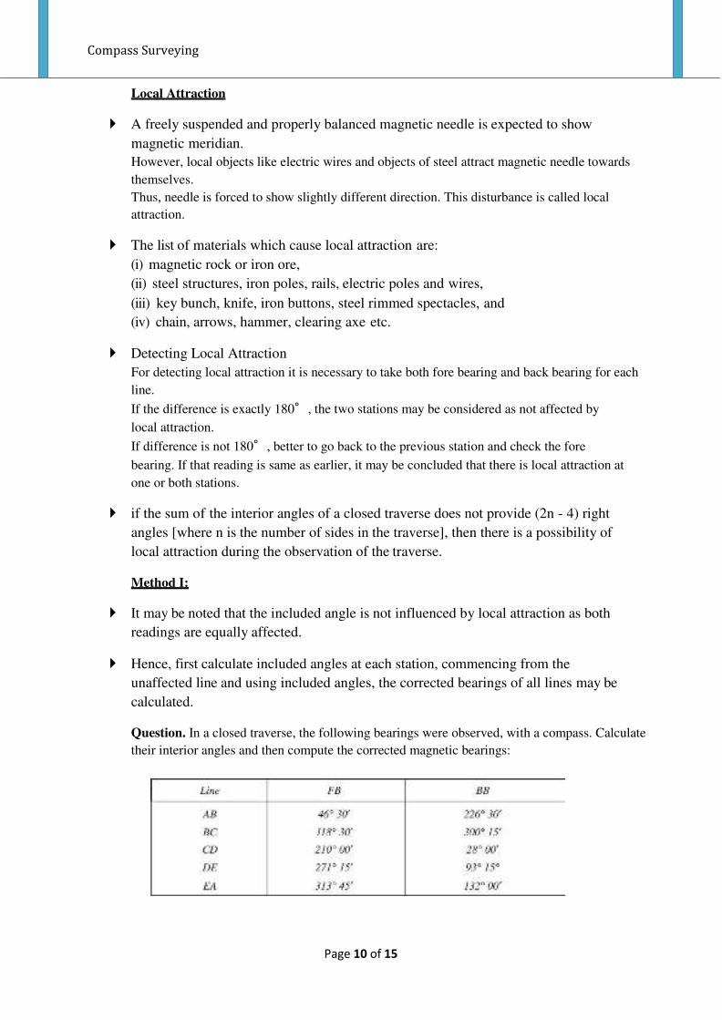
Question. In a closed traverse, the following bearings were observed, with a compass. Calculate
their interior angles and then compute the corrected magnetic bearings:

Compass Surveying
Page 11 of 15
Solution: Step 1 : Find line which has zero local attraction . This is done by finding difference of
Back Bearing and Forebearing of line.
We find that Line AB has zero local attraction.
FB of AB – BB of BA = 226* 30’ – 46* 30’ = 180*
Step 2: Find Internal Angles from the observed readings given in question.
Sum of Internal angles should be equal to = (2n-4) x 90 = ( 2 x 5 – 4 ) x 90 = 540 degrees
The angles found will always be correct.
Step 3:
Start from the Line having Zero Local Attraction :
In this case Line AB has Zero Local Attraction.
Draw Line AB , then write Fore Bearing of AB and Back Bearing of BA.

Compass Surveying
Page 12 of 15
Subtract Angle B from Back Bearing BA to Find Fore bearing of Next line that is BC.
Continue above steps for all lines.
2nd
Method
In this method, errors due to local attraction at each of the affected station is found starting
from the bearing of a unaffected local attraction, the bearing of the successive lines are
adjusted.
Correction = Correct reading – Observed reading
Solve Above Question by 2nd
Method.
Solution: Since, the difference between FB and BB of line AB is exactly 180°, stations A and
B are not affected by local attraction. Hence, corrections to the observed bearings at A and B
are zero.
Hence reading of AB, AE from station A, And reading of BA and BC from Station B will
considered to be correct.

Compass Surveying
Page 13 of 15

Compass Surveying
Page 14 of 15

Compass Surveying
Page 15 of 15

1 |Levelling
What is levelling ?
It may be defined as
1) the art of determining the elevations of given points above or below a datum line or
2) Establishing given points of required heights above or below the datum line.
Uses of levelling
(i) to determine or to set the plinth level of a building.
(ii) to decide or set the road, railway, canal or sewage line alignment.
(iii) to determine or set various levels of dams, towers, etc.
(iv) to determine the capacity of a reservoir.

2 |Levelling
Definitions
Level Surface- A surface parallel to the mean spheroid of the earth is called a level surface. All points
lying on a level surface are equidistant from the centre of the earth.
Level Line - The line drawn on the level surface is known as a level line. This line is perpendicular to
the direction of gravity at all points
.
Horizontal Surface/Plane- A surface/plane tangential to level surface at a given point is called
horizontal surface/plane at that point.
Horizontal Line/Axis – A horizontal line through a point is line drawn on Horizontal surface through
that point. This line is perpendicular to the direction of gravity at the point.
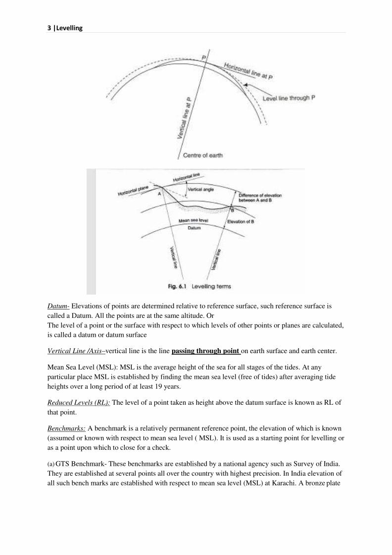
3 |Levelling
Datum- Elevations of points are determined relative to reference surface, such reference surface is
called a Datum. All the points are at the same altitude. Or
The level of a point or the surface with respect to which levels of other points or planes are calculated,
is called a datum or datum surface
Vertical Line /Axis–vertical line is the line passing through point on earth surface and earth center.
Mean Sea Level (MSL): MSL is the average height of the sea for all stages of the tides. At any
particular place MSL is established by finding the mean sea level (free of tides) after averaging tide
heights over a long period of at least 19 years.
Reduced Levels (RL): The level of a point taken as height above the datum surface is known as RL of
that point.
Benchmarks: A benchmark is a relatively permanent reference point, the elevation of which is known
(assumed or known with respect to mean sea level ( MSL). It is used as a starting point for levelling or
as a point upon which to close for a check.
(a) GTS Benchmark- These benchmarks are established by a national agency such as Survey of India.
They are established at several points all over the country with highest precision. In India elevation of
all such bench marks are established with respect to mean sea level (MSL) at Karachi. A bronze plate

4 |Levelling
provided on the top of a concrete pedestal with its elevation engraved serves as GTS bench mark. It is
well protected so that its position is not disturbed by animals or any unauthorized person.
(b) Permanent Benchmark- These are the benchmarks established by state government agencies like
PWD. They are established with reference to GTS benchmarks. They areusually on the corner of
plinth of public buildings.
(c) Arbitrary Benchmark- In many engineering projects the difference in elevations of neighbouring
points is more important than their reduced level with respect to mean sealevel. In such cases a
relatively permanent point, like plinth of a building or corner of aculvert, are taken as benchmarks,
their level assumed arbitrarily such as 100.0 m,300.0 m, etc.
(d) Temporary Benchmark: This type of benchmark is established at the end of the day’swork, so that the next day work may be continued from that point. Such point should be on a permanent object so
that next day it is easily identified.
Levelling Instruments
1. Level
A level is an instrument giving horizontal line of sight and magnifying the reading at a far away
distance.
It consists of the following parts:
(i) A telescope to provide a line of sight
(ii) A level tube to make the line of sight horizontal and
(iii) A levelling head to level the instrument.
Types of levels:-
1) Dumpy level 2) Cooke’s Reversible level
3) Cushing’s Level 4) Wye (or, Y) level 5) Auto Level 4)
DUMPY LEVEL (Important)

4 |Levelling notes Part 2 NKT

5 |Levelling
In short, above can be written as

6 |Levelling
2. Levelling Staff
The levelling staff is a rectangular rod having graduations.
The staff is provided with a metal shoes at its bottom to resist wear and tear.
The foot of the shoe represents zero reading. Levelling staff may be divided into two groups :-
1. Self reading staff: This staff reading is directly read by the instrument man through
telescope.
(a) Solid staff: It is a single piece of 3 m.
(b) Folding staff :A staff of two pieces each of 2 m which can be folded one over the other.
(c)Telescopic staff:A staff of 3 pieces with upper one solid and lower two hollow. The upper
part can slide into the central one and the central part can go into the lower part. Each length
can be pulled up and held in position by means of brass spring. The total length may be 4 m
or 5 m.
2. Target staff: If the sighting distance is more, instrument man finds it difficult to read self
reading staff. In such case a target staff shown in may be used. Target staff is similar to self
reading staff, but provided with a movable target.

7 |Levelling
Temporary Adjustments of A Level (Important – 7 marks Question)
The adjustments to be made at every setting of the instrument are called temporary
adjustments. The following three adjustments are required for the instrument whenever set
over a new point before taking a reading:
(i) Setting (ii) Levelling and (iii) Focussing.
A. Setting
Tripod stand is set on the ground firmly so that its top is at a convenient height. Then the level
is fixed on its top. By turning tripod legs radially or circumferentially, the instrument is
approximately levelled.
Some instruments are provided with a less sensitive circular bubble on tribrach for this
purpose.
B. Levelling
The procedure of accurate levelling with three levelling screw is as given below:
(i) Loosen the clamp and turn the telescope until the bubble axis is parallel to the line joining
any two screws .
(ii) Turn the two screws inward or outward equally and simultaneously till bubble is centred.
(iii) Turn the telescope by 90° so that it lies over the third screw [Fig. 15.4 (b)] and level the
instrument by operating the third screw.
(iv) Turn back the telescope to its original position and check the bubble.
Repeat steps (ii) to (iv) till bubble is centred for both positions of the telescope.
(v) Rotate the instrument by 180°. Check the levelling.
C. Focussing
Focussing is necessary to eliminate parallax while taking reading on the staff. The following
two steps are required in focussing:
(i) Focussing the eyepiece:For this, hold a sheet of white paper in front of telescope and rotate
eyepiece in or out till the cross hairs are seen sharp and distinct.
(ii) Focussing the objective:For this telescope is directed towards the staff and the focussing
screw is turned till the reading appears clear and sharp.
The Relation Between Bubble Tube Axis, Optical Axis And Vertical Axis With The Line Of
Collimation (Important)
Vertical axis is perpendicular to Horizontal axis, Line of collimation(line of sight), bubble tube axis,
optical axis.

8 |Levelling
Line of collimation( line of sight) is parallel to Bubble tube axis, optical axis
& perpendicular to Vertical axis.
Bubble tube Axis is parallel to Line of collimation, optical axis.
& perpendicular to vertical axis.
Technical Terms used in Levelling :
Height of instrument (H.I.) or height of collimation: For any set up of the level, the elevation of the
line of sight is the height of instrument. (H.I. = hA+ SA in Fig.)
Station: A station is the point where the levelling staff is held. (Points A, a, b, B, c, and C in Fig.)
Back sight (B.S.): It is the first reading taken on the staff after setting up the level usually to
determine the height of instrument.
It is usually made to some form of a bench mark (B.M.) or to the points whose elevations have
already been determined.
When the instrument position has to be changed, the first sight taken in the next section is also a back
sight. (Staff readings S1and S5 in Fig).
Fore sight (F.S.): It is the last reading from an instrument position on to a staff held at a point.It is
thus the last reading taken within a section of levels before shifting the instrument to the next section,
and also the last reading taken over the whole series of levels. (Staff readings S4 and S7in Fig.).
Change point (C.P.) or turning point: A change point or turning point is the point where both the
fore sight and back sight are made on a staff held at that point. A change point is required before

9 |Levelling
moving the level from one section to another section. By taking the fore sight the elevation of the
change point is determined and by taking the back sight the height of instrument is determined.The
change points relate the various sections by making fore sight and back sight at the same point.(Point
B in Fig).
Intermediate sight (I.S.): The term ‘intermediate sight’ covers all sightings and consequent staff readings made between back sight and fore sight within each section.Thus, intermediate sight station
is neither the change point nor the last point. (Points a, b, and c in Fig. ).
Reduced level (R.L.): Reduced level of a point is its height or depth above or below the assumed
datum.It is the elevation of the point.
Rise and fall: The difference of level between two consecutive points indicates a rise or a fall
between the two points. In Fig. , if (SA– SB) is positive, it is a rise and if negative, it is a fall. Rise
and fall are determined for the points lying within a section.
Section: A section comprises of one back sight, one fore sight and all the intermediate sights taken
from one instrument set up within that section.
Parallax: is a displacement or difference in the apparent position of an object viewed along two
different lines of sight, and is measured by the angle or semi-angle of inclination between those two
lines.
Focal length- The distance from the focal point of a lens or mirror to the reflecting surface of the
mirror or the centre point of the lens. The focal length of an optical system is a measure of how
strongly the system converges or diverges light.
Methods Of Levelling
Simple Levelling- It is the method used for finding difference between the levels of two nearby
points.
Differential Levelling
If the distance between two points A and B is large, it may not be possible to take the readings on A
and B from a single setting. In such situation differential levelling is used. In differential levelling the
instrument is set atmore than one position, each shifting facilitated by a change point. Figure shows a
scheme of such setting.

10 |Levelling
Fly levelling
The levelling operation in which only BS and FS readings are taken and no intermediate sights are
observed is known as fly levelling.
Fly levelling is done for connecting the benchmark to the starting point of any project. In such
levelling, no horizontal distances are required to be measured.
Methods for Finding Reduced Levels of points
Height of Collimation method

11 |Levelling
Check : Sum of Back Reading -Sum of Fore Reading= Last R.L. - First R.L.
Note- Ht. of instrument changes at every Change Point.
New Ht of Instument = RL of that point + Staff reading (Back Sight)
Staff Reading (IS /FS ) = Ht of Instrument (will be same)– Staff reading(changes at every point)
Example. The following readings were taken with a level and 4 m staff.
Draw up a level book page and reduce the levels by the Ht of Collimation method. 0.578 B.M.(=
58.250 m), 0.933, 1.768, 2.450, (2.005 and 0.567) C.P., 1.888, 1.181, (3.679 and 0.612) C.P., 0.705,
1.810.

12 |Levelling
Rise and Fall method
Compute all rises & falls
Start at a Benchmark (BM) with known Reduced Level (RL)
To get RL of next station:
add rise to previous RL, or subtract fall from previous RL
Repeat for all subsequent stations
Check : Sum of Back Reading-Sum of Fore Reading = Total Rise -Total Fall = Last R.L. -First R.L.
Solving above question by Rise and fall method.
Q. The following staff reading were observed successively with a level, the instrument having been
moved after third, sixth and eighth reading 2.228, 1606, 0.988, 2.090, 2.864, 1.262, 0.602, 1.982,
1.044, 2.864 Enter the above readings in a page of level book and calculate the RL of points if the first
reading was taken with staff hold on a bench mark of 432.384 m .

13 |Levelling
By rise and fall method
By height of instrument method
Apply Check = 5.964-6.916 = 431.432 -432.384 = -0.952

14 |Levelling
Factors to be considered in selecting contour Interval

15 |Levelling
Prismatic Compass
A magnetic needle of broad form (1) is balanced on a hard and pointed steel pivot (2). The top of the
pointed pivot is protected with agate cap (3). An aluminium graduated disk (4) is fixed to the top of
the needle. The graduations are from zero to 360° in clockwise direction when read from top. The
direction of north is treated as zero degrees, east as 90°, south as 180° and west as 270°. However,
while taking the readings observations are at the other end of line of sight. Hence, the readings are
shifted by 180° and graduations are marked as shown in Fig.. The graduations are marked inverted
because they are read through a prism.
The line of sight consists of object unit and the reading unit. Object unit consists of a slit metal frame
(5) hinged to the box. In the centre the slit is provided with a horse hair or a fine wire or thread (6).
The metal frame is provided with a hinged mirror (7), which can be placed upward or downward on
the frame. It can be slided along the frame. The mirror can be adjusted to view objects too high or too
low from the position of compass. Reading unit is provided at diametrically opposite edge. It consists
of a prism (8) with a sighting eye vane (9). The prism magnifies the readings on the graduation disk
just below it. For focussing, the prism is lowered or raised on the frame carrying it and then fixed with
the stud (10). Dark sunglasses (11) provided near the line of sight can be interposed if the object to be
sighted is bright (e.g.,sun).
The bottom of the box (12) which is about 85 mm to 110 mm supports the pivot of needle firmly at its
centre. The object vane and the prism are supported on the sides of the box. The box is provided with
a glass (13) lid which protects the graduation disc at the same time permit the direct reading from the
top. When the object vane is folded on the glass top it presses a lifting pin (14) which activates lifting
lever (15) lifts the needle off the pivot. Thus, it prevents undue wear of pivot point. While taking

C o n t o u r s
reading, if graduation disc vibrates, it can be dampened with a spring (16). For pressing
spring a knob or brake pin (17) is provided on the box. When not in use prism can be
folded over the edge of the box. The box is provided with a lid to close it when the
compass is not in use. The box is provided with a socket to fit it on the top of a tripod.
Contours A contour line is a imaginary line which connects points of equal elevation.
Such lines are drawn on the plan of an area after establishing reduced levels of several
points in the area.
A numerical value placed upon a contour line to denote its elevation relative to a given
datum, usually mean sea level is called Contour Value
The contour lines in an area are drawn keeping difference in elevation of between two
consecutive lines constant.
The contour interval of a contour map is the difference in elevation between successive
contour lines. For example, Figure shows contours in an area with contour interval of 1 m.
On contour lines the level of lines is also written.
Characteristics of Contours
1. Contour lines must close, not necessarily in the limits of the plan.
2. Widely spaced contour indicates flat surface.
3. Closely spaced contour indicates steep ground.
4. Equally spaced contour indicates uniform slope.
5. Irregular contours indicate uneven surface.
6. Approximately concentric closed contours with decreasing values towards centre indicate a
pond.

C o n t o u r s
6. Approximately concentric closed contours with decreasing values towards centre indicate a
pond
7. Approximately concentric closed contours with increasing values towards centre indicate
hills.
8. Contour lines with U-shape with convexity towards lower ground indicate ridge

C o n t o u r s
9. Contour lines with V-shaped with convexity towards higher ground indicate valley
10. Contour lines generally do not meet or intersect each other.
11. If contour lines are meeting in some portion, it shows existence of a vertical cliff
12. If contour lines cross each other, it shows existence of overhanging cliffs or a cave.

C o n t o u r s