what will we do for beam preparation: injection and beam dump
DESCRIPTION
What will we do for Beam Preparation: Injection and Beam Dump. Jan Uythoven Thanks to M.Barnes , E.Carlier , L.Ducimetière , B.Goddard , R.Jones , Y.Kadi , V.Kain , M.Meddahi , V.Mertens and many more. Injection and Beam Dump. Changes to the Injection and Beam Dumping Systems - PowerPoint PPT PresentationTRANSCRIPT

What will we do for Beam Preparation: Injection and
Beam Dump
Jan UythovenThanks to
M.Barnes, E.Carlier, L.Ducimetière, B.Goddard, R.Jones, Y.Kadi, V.Kain, M.Meddahi, V.Mertens and many more
1

Chamonix, 5 February 2009 2
Injection and Beam Dump
Changes to the Injection and Beam Dumping Systems Transfer Lines Injection kickers MKI Beam Dump kickers MKD & MKB Their controls
Requirements for commissioning before beam Interfaces Time
Jan Uythoven, TE/ABT

Chamonix, 5 February 2009 3
What is New:Injection System
Injection kickers MKI Worked fine, but delicate equipment operating “near the edge” Many - partly conflicting - design requirements (kick strength, rise
time, flat-top ripple, aperture, beam impedance, vacuum, …)
Jan Uythoven, TE/ABT
Chamonix, 5 February 2009 4
Injection Kickers MKI
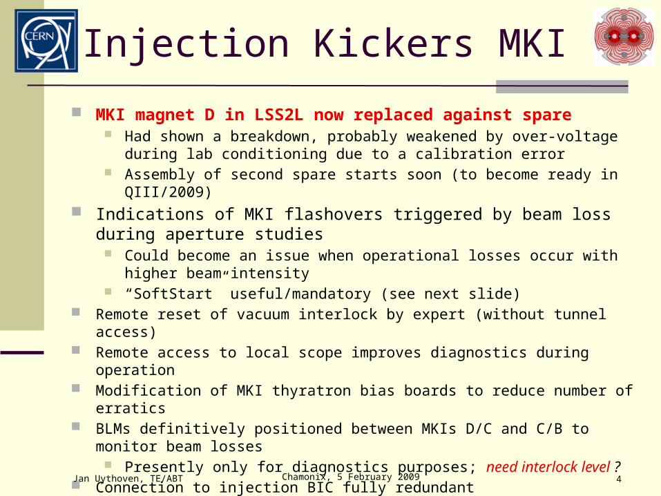
MKI magnet D in LSS2L now replaced against spare Had shown a breakdown, probably weakened by over-voltage during lab
conditioning due to a calibration error Assembly of second spare starts soon (to become ready in QIII/2009)
Indications of MKI flashovers triggered by beam loss during aperture studies
Could become an issue when operational losses occur with higher beam intensity
“SoftStart” useful/mandatory (see next slide) Remote reset of vacuum interlock by expert (without tunnel access) Remote access to local scope improves diagnostics during operation Modification of MKI thyratron bias boards to reduce number of erratics BLMs definitively positioned between MKIs D/C and C/B to monitor beam losses
Presently only for diagnostics purposes; need interlock level ? Connection to injection BIC fully redundant Tri-axial cables for transfer line BCT MKI synchronisation (OASIS)
Jan Uythoven, TE/ABT

Chamonix, 5 February 2009 5
V0
V1
V3e
V2m
N01
N1
N2m
dV01
dV12
NORMAL MODE
V4n
N12
Nn
NORMAL MODE
END
COND
ITIO
NING
V0
V1
V3e
V2m
N01
N1
N2m
dV01
dV12
NORMAL MODE
V4n
N12
Nn
NORMAL MODE
END
COND
ITIO
NING
END
COND
ITIO
NING
MKI “SoftStart”
New SoftStart will have more configuration parameters
Faster ramp-up at lower voltages Variation of pulse length All parameters under RBAC
Expect now standard duration of about 10 minutes
Relies on RBAC, LSA, timing etc. Only to be used when machine is in
‘operational mode’ and data bases etc. are operational
Jan Uythoven, TE/ABT
Program to compensate for small drop in conditioning during extended periods without pulsing, before applying the full high voltage for injection
Implies to anticipate 30 minute SoftStart period in injection preparation (can be done by sequencer, in parallel with other preparation activities)
MKI GUI to be updated by OP

Chamonix, 5 February 2009 6
Collimators and Absorbers
Injection absorbers TDI (leaky seals on motorisations) LSS2L presently out, back beginning of March LSS8R out when access to zone, back end of April
Transfer line collimators TCDI (screws/springs, roller cages) TCDI in TI 8 tunnel repaired before end March (SPS shutdown) TI 8 TCDI in LHC tunnel: repair depends on LHC access to LSS8,
before end of March Will all need to be recommissioned and recalibrated
Calibration is remote
Jan Uythoven, TE/ABT

Chamonix, 5 February 2009 7
Transfer Lines
TI 8 BPMs reading in both planes and 4 additional BPMs towards the end of the line.
Integrate in LSA, logging, YASP TI 2 for 2010
TI 2 and TI 8 full alignment campaign (for details see Malika’s talk) All power converters on FESA Septum MSI stray field: run MSI in DC ?
To be tested during dry runs ! Need a smooth way of switching off MSI at end of injection
Jan Uythoven, TE/ABT
R. Steinhagen, J. Wenninger
Beam Positionrms H/V
time

Chamonix, 5 February 2009 8
Requirements Commissioning
Jan Uythoven, TE/ABT
Commissioning for 2009:• LHC Transfer Lines
• Hardware Commissioning during SPS cold checkout• Test modified collimators and new BPMs. Test MSI in DC ?• Beam tests until downstream TED to be planned for May. Test high intensity?
• LHC Injection System• MKI control system commissioning starting in March. HV required.• HV conditioning end of March & April• Interface to other systems, operation from CCC in May. Dry runs required.
• No staged approach in Hardware Commissioning possible
Coordinate with LHC works !
Chamonix, 5 February 2009 9
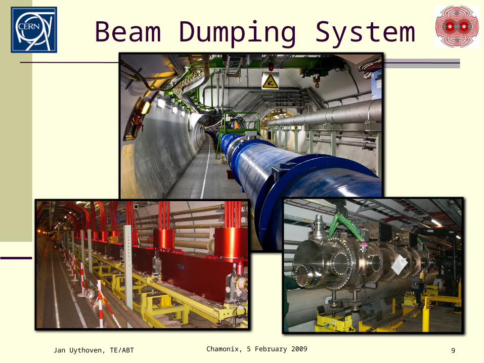
Beam Dumping System
Jan Uythoven, TE/ABT

Chamonix, 5 February 2009 10
Dilution Kickers MKB Additional dilution magnets MKB installed for 2009:
MKBH inst. will become nominal: 4 magnets (in 2 tanks) MKBV will have 4 magnets (in 2 tanks); nominal is 6 magnets
Jan Uythoven, TE/ABT
50 s
Moment of breakdown
I [kA]
Flashovers occurred in some of the installed magnets
Weak insulator identified and replaced on all systems.
Magnets with breakdown replaced (coil issue)
Dangerous “common mode” failure
Conductance will be reduced and will have additional turbo pumps installed
Measured MKB wave form

Chamonix, 5 February 2009 11
Extraction Kickers MKD Cooling The temperature of the MKD generator has been found to
significantly affect the MKD kick strength
Jan Uythoven, TE/ABT
Measure kick currents at 1 TeV
Tunnel temperature down by 4 degrees, kick gone up by about 0.7 – 0.8 %,
Kick response appears to lag behind temperature change, which seems logical.
Yellow curve is tunnel temp.dt = 4 degrees
Starting 13:00, biggest drop reached at 20:30
stable 24 hours later
Series data start at 15:00, so in the middle of biggest drop in temp
6 hours
15:00
24 hours

Chamonix, 5 February 2009 12
MKD Temperature Changes
Temperature changes due to UA temperature variation Temperature changes due to being at ‘stand-by’ at high beam
energies
Jan Uythoven, TE/ABT
D T = 2 C + 2 C = 4 C by running at 7 TeV
Generator Temperature

Chamonix, 5 February 2009 13
MKD Cooling
Peltier temperature regulation units installed on each of the 30 MKD generators Together with temperature isolation and ventilation Humidity sensor & interlock
Set regulation of tunnel temperature = 23 degrees Interlock +/- 1 degree Synchronous Beam Dump if temperature gets out of
regulation window Restart only possible when correct conditions are back
Some weeks of operational experience required before first beam
Jan Uythoven, TE/ABT

Chamonix, 5 February 2009 14
Other Changes to the LBDS
Internal Post Operational Checks (IPOC): Second MKD current measurement by Rogowski system:
will be used for IPOC with realistic limits Installation of a fast detection system of mains / UPS
instabilities at the level of the TSU Directly connected to the re-trigger lines
React after t > 75 ms (adjustable) with asynchronous beam dump
On top of existing detection system at a higher level which triggers a synchronous dump (t > 60 ms)
One week of testing needed
Jan Uythoven, TE/ABT
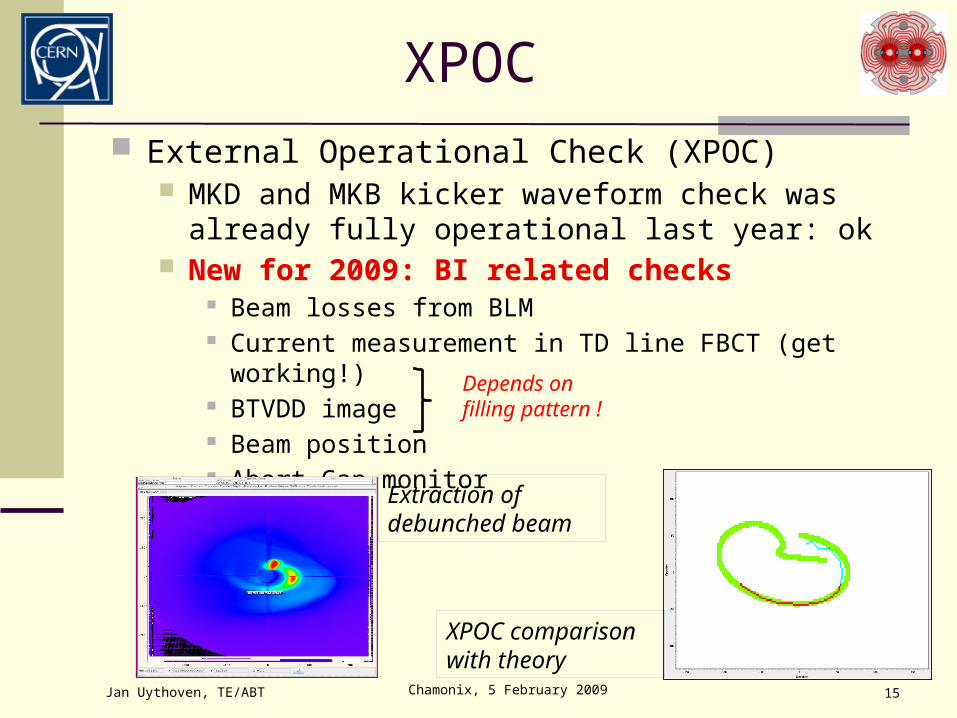
XPOC External Operational Check (XPOC)
MKD and MKB kicker waveform check was already fully operational last year: ok
New for 2009: BI related checks Beam losses from BLM Current measurement in TD line FBCT (get working!) BTVDD image Beam position Abort Gap monitor
Jan Uythoven, TE/ABT Chamonix, 5 February 2009 15
Depends on filling pattern !
Extraction of debunched beam
XPOC comparison with theory

Chamonix, 5 February 2009 16
TCDQ Energy Interlock
TCDQ position is a function of energy, and gets triggered by a timing event (like collimators)
Sensitive to errors related to timing system For 2009 there will be an ‘independent’ check on the
TCDQ position, taking the beam energy as input parameter
Dump the beam if the TCDQ is at the wrong position as expected relative to the beam energy
Jan Uythoven, TE/ABT

Chamonix, 5 February 2009 17
Running from the CCC
Reliability Run, as done in 2008, produced sufficient data for ‘equipment statistics’
However, 2009 will need at least four weeks of effective running to obtain failure statistics after system modifications MKD cooling, new MKBs
Well organised dry runs for testing interface to other equipment For LBDS try to start in June, in parallel with last phases of
hardware commissioning
Jan Uythoven, TE/ABT
Beam 1 Beam 2# Pulses 23’534 15’469
Time considered 10.5 months 9.1 months
Continuous running (p <13 h)
2.7 months 1.7 months
Data from 8/11/07 to 19/09/08Jan Uythoven, TE/ABT
Beam 2

Chamonix, 5 February 2009 18
LBDS Commissioning
Equipment ‘controls’ commissioning MKD cooling – full re-testing of generators since
fully “de-cabled” to install cooling New MKB generators HV required for testing at controls level
Local operation under HV Energy reference locally generated Check operation up to 7 TeV Generate calibration tables used for generation of
settings / checking of the settings Generation of IPOC and XPOC limits for MKD and
MKB
Jan Uythoven, TE/ABT
1
2

Chamonix, 5 February 2009 19
LBDS Remote Operation (I)
Remote operation from the CCC Energy reference can be
BETSsim: simulation program for generation of energy reference Main Bends; nominally 4 adjacent sectors, during transition period
can split signal from one or more octants Energy value distributed by the timing system as part of the
Safe Machine Parameters Used by other systems: BLMs, Collimators etc. Only available from the moment BETSsim back in operation
Jan Uythoven, TE/ABT
3a
Coordination required !!

Chamonix, 5 February 2009 20
LBDS Remote Operation (II)
Remote operation from the CCC Dry runs Interface to many systems:
BIC, closing the loop: new arming sequence Will need to mask many systems (incl. access) to be able
to close the loop Foresee to alternate ‘masked’ and ‘unmasked’ BIC periods
of 1 – 2 weeks Access system (mask on the access system level) Timing & RF -> synchronisation Q4, MSD XPOC, LSA, MCS, RBAC Abort Gap Monitoring Injection System
Jan Uythoven, TE/ABT
3b
Chamonix, 5 February 2009 21
Constraints for Commissioning For all commissioning work High Voltage is required Start (only) week 14 when cabling campaign is finished Always run complete beam dumping system
MKD 63 MKB 67, MKD 67 MKB 63 Timing and synchronisation as of week 28:
BIC, RF, Timing, Access, LSA, RBAC, XPOC, Sequencer Estimate at least 4 weeks of effective LBDS running from CCC
required to get everything running smoothly inlcuding reliability of new / modified systems
8 calendar weeks if 50 % effective period with BIC masked Main Bends as energy reference as much as possible before first beam
Only one switch-over from BETSsim to Main Bends Need ‘Main Bends’ time to make checks on BETS Can be staged 1…4 octants
No system commissioning in stages: needs to be fully operational and checked before first beam
Jan Uythoven, TE/ABT
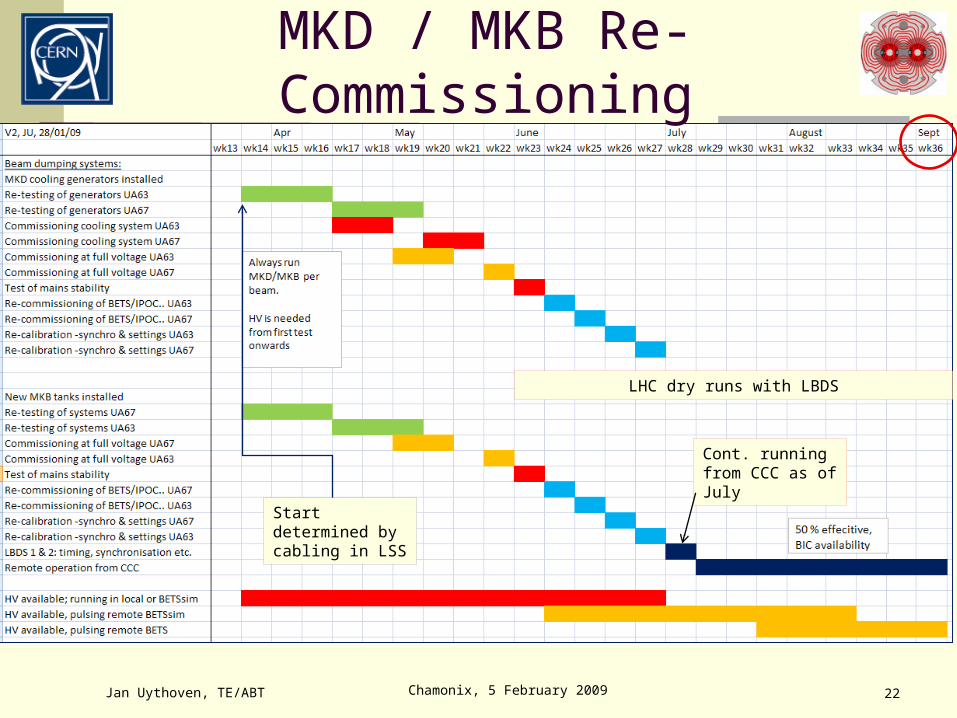
Chamonix, 5 February 2009 22
MKD / MKB Re-Commissioning
Jan Uythoven, TE/ABT
Start determined by cabling in LSS
Cont. running from CCC as of July
LHC dry runs with LBDS

Chamonix, 5 February 2009 23
Conclusions Injection System:
TI 8 BPMs upgraded, TI 2 and TI 8 realigned TL Beam commissioning up to downstream TEDs end May: close 3 LHC sectors / test One injection kicker MKI replaced; additional BLMs; new SoftStart Commissioning does not seem to be time-critical, no major surprises expected
Beam Dumping System: Doubled the number of dilution kickers MKB Added cooling (& interlocks !) to all 30 MKD generators Commissioning time-critical due to late start and a lot of work Interface to many other systems known to be important and time consuming to test:
BIC availability Transmission of Energy via SMP, used by others Will need at least 8 calendar weeks running from CCC, assuming 50 % availability With present planning start from CCC in July (wk 28), finish September (wk 36)
Dry runs required for both the injection and the beam dumping system No staged ‘non-beam’ commissioning possible Thorough commissioning of the fully connected system mandatory for Machine Protection
Energy tracking & triggering
Jan Uythoven, TE/ABT