what’s new in cadds 5i release 12 - john j. jacobs · toolpath animation for fastening ......
TRANSCRIPT

What’s New in
CADDS® 5i Release 12
Release 12
DOC40175-010
Parametric Technology Corporation
Copyright © 2001 Parametric Technology Corporation. All Rights Reserved.User documentation from Parametric Technology Corporation (PTC) is subject to copyright laws of the UnitedStates and other countries and is provided under a license agreement, which restricts copying, disclosure, anduse of such documentation. PTC hereby grants to the licensed user the right to make copies in printed form ofPTC user documentation provided on software or documentation media, but only for internal, noncommercial useby the licensed user in accordance with the license agreement under which the applicable software anddocumentation are licensed. Any copy made hereunder shall include the Parametric Technology Corporationcopyright notice and any other proprietary notice provided by PTC. User documentation may not be disclosed,transferred, or modified without the prior written consent of PTC and no authorization is granted to make copiesfor such purposes.
Information described in this document is furnished for general information only, is subject to change withoutnotice, and should not be construed as a warranty or commitment by PTC. PTC assumes no responsibility orliability for any errors or inaccuracies that may appear in this document.
The software described in this document is provided under written license agreement, contains valuable tradesecrets and proprietary information, and is protected by the copyright laws of the United States and othercountries. UNAUTHORIZED USE OF SOFTWARE OR ITS DOCUMENTATION CAN RESULT IN CIVILDAMAGES AND CRIMINAL PROSECUTION.
Registered Trademarks of Parametric Technology Corporation or a SubsidiaryAdvanced Surface Design, CADDS, CADDShade, Computervision, Computervision Services,Electronic Product Definition, EPD, HARNESSDESIGN, Info*Engine, InPart, MEDUSA, Optegra,Parametric Technology, Parametric Technology Corporation, Pro/ENGINEER, Pro/HELP, Pro/INTRALINK,Pro/MECHANICA, Pro/TOOLKIT, PTC, PT/Products, Windchill, InPart logo, and PTC logo.
Trademarks of Parametric Technology Corporation or a Subsidiary3DPAINT, Associative Topology Bus, Behavioral Modeler, BOMBOT, CDRS, CounterPart, CV, CVact, CVaec,CVdesign, CV-DORS, CVMAC, CVNC, CVToolmaker, DesignSuite, DIMENSION III, DIVISION, DVSAFEWORK,DVS, e-Series, EDE, e/ENGINEER, Electrical Design Entry, Expert Machinist, Expert Toolmaker,Flexible Engineering, i-Series, ICEM, Import Data Doctor, Information for Innovation, ISSM, MEDEA,ModelCHECK, NC Builder, Nitidus, PARTBOT, PartSpeak, Pro/ANIMATE, Pro/ASSEMBLY, Pro/CABLING,Pro/CASTING, Pro/CDT, Pro/CMM, Pro/COMPOSITE, Pro/CONVERT, Pro/DATA for PDGS, Pro/DESIGNER,Pro/DESKTOP, Pro/DETAIL, Pro/DIAGRAM, Pro/DIEFACE, Pro/DRAW, Pro/ECAD, Pro/ENGINE, Pro/FEATURE,Pro/FEM-POST, Pro/FLY-THROUGH, Pro/HARNESS-MFG, Pro/INTERFACE for CADDS 5,Pro/INTERFACE for CATIA, Pro/LANGUAGE, Pro/LEGACY, Pro/LIBRARYACCESS, Pro/MESH, Pro/Model.View,Pro/MOLDESIGN, Pro/NC-ADVANCED, Pro/NC-CHECK, Pro/NC-MILL, Pro/NC-SHEETMETAL, Pro/NC-TURN,Pro/NC-WEDM, Pro/NC-Wire EDM, Pro/NCPOST, Pro/NETWORK ANIMATOR, Pro/NOTEBOOK, Pro/PDM,Pro/PHOTORENDER, Pro/PHOTORENDER TEXTURE LIBRARY, Pro/PIPING, Pro/PLASTIC ADVISOR,Pro/PLOT, Pro/POWER DESIGN, Pro/PROCESS, Pro/REPORT, Pro/REVIEW, Pro/SCAN-TOOLS,Pro/SHEETMETAL, Pro/SURFACE, Pro/VERIFY, Pro/Web.Link, Pro/Web.Publish, Pro/WELDING,Product Structure Navigator, PTC i-Series, Shaping Innovation, Shrinkwrap, The Product Development Company,Virtual Design Environment, Windchill e-Series, CV-Computervision logo, DIVISION logo, and ICEM logo.
Third-Party TrademarksOracle is a registered trademark of Oracle Corporation. Windows and Windows NT are registered trademarks ofMicrosoft Corporation. Java and all Java based marks are trademarks or registered trademarks of SunMicrosystems, Inc. CATIA is a registered trademark of Dassault Systems. PDGS is a registered trademark of FordMotor Company. SAP and R/3 are registered trademarks of SAP AG Germany. FLEXlm is a registered trademarkof GLOBEtrotter Software, Inc. VisTools library is copyrighted software of Visual Kinematics, Inc. (VKI) containingconfidential trade secret information belonging to VKI. HOOPS graphics system is a proprietary software productof, and copyrighted by, Tech Soft America, Inc. All other brand or product names are trademarks or registeredtrademarks of their respective holders.

UNITED STATES GOVERNMENT RESTRICTED RIGHTS LEGENDThis document and the software described herein are Commercial Computer Documentation and Software,pursuant to FAR 12.212(a)-(b) or DFARS 227.7202-1(a) and 227.7202-3(a), and are provided to the Governmentunder a limited commercial license only. For procurements predating the above clauses, use, duplication, ordisclosure by the Government is subject to the restrictions set forth in subparagraph (c)(1)(ii) of the Rights inTechnical Data and Computer Software Clause at DFARS 252.227-7013 or Commercial ComputerSoftware-Restricted Rights at FAR 52.227-19, as applicable.
Parametric Technology Corporation, 140 Kendrick Street, Needham, MA 02494-27148 January 2001

Table of Contents
PrefaceRelated Documents _________________________________________ ixBook Conventions ___________________________________________ xWindow Managers and the User Interface ____________________ xiOnline User Documentation __________________________________ xiOnline Command Help ______________________________________ xiiPrinting Documentation _____________________________________ xiiResources and Services _____________________________________ xiiiDocumentation Comments _________________________________ xiii
New Features and EnhancementsGeneral Enhancements _________________________________________ 1-2
Networked Drives on Windows NT _____________________________ 1-2
CVGPII Postprocessor and Intellepost on Windows NT___________ 1-2
Setting Tolerance for System Library Features___________________ 1-2
Best Practices ________________________________________________ 1-3
Dynamic Loading on Windows NT ________________________________ 1-4
Dynamic Loading of CADDS 5i ISSM on Windows NT ____________ 1-4
Dynamic Loading of Custom CVact Menus on Windows NT _____ 1-4
Dynamic Loading of CVMAC Using CALLF Routines_____________ 1-5
CADDS Centric Associative Topology Bus _________________________ 1-6
The DXF Converter ______________________________________________ 1-8
What’s New in CADDS 5i Release 12 Contents-v

Parametric Modeling _____________________________________________ 1-9
Update Ppart _________________________________________________ 1-9
Edit Ppart _____________________________________________________ 1-9
Reuse History__________________________________________________ 1-9
Performing History Operation Using Unified History Menu _______ 1-11
History Tree _________________________________________________ 1-15
Sweeping a Face with Initial Offset Angle_____________________ 1-16
Plotting ________________________________________________________ 1-18
Plotting the Raster Output ___________________________________ 1-18
Plotting the History Tree and the Assembly Structure ___________ 1-19
Drafting and Dimensioning _____________________________________ 1-20
Enhancements in CSD _______________________________________ 1-20
Aligning Dimensions _________________________________________ 1-20Aligning Two Dimensions __________________________________ 1-20Aligning Multiple Dimensions ______________________________ 1-21
Defining a Group of Dimensions ______________________________ 1-21Dragging the Group of Dimensions ________________________ 1-21Breaking a Dimension from the Group _____________________ 1-21
Using Dimension Update Management _______________________ 1-22
Hidden Line Removal___________________________________________ 1-23
Integrated 3D Sketcher _________________________________________ 1-25
Importing DesignView Profiles ________________________________ 1-25
Importing Explicit Geometry Directly__________________________ 1-25
Defining a Cplane in Sketcher _______________________________ 1-25
Redefining a Vpane _________________________________________ 1-26
Previewing Sketch Library ____________________________________ 1-26
Editing and Applying Sketches _______________________________ 1-27
Ascertaining Status of Geometry _____________________________ 1-29
Creating Point Entity_________________________________________ 1-29
Mirroring and Sewing Functions ______________________________ 1-30
Selecting by Window for Import ______________________________ 1-31
Creating Chamfers __________________________________________ 1-31
Filleting _____________________________________________________ 1-34
Creating Pattern Geometry __________________________________ 1-35
Contents-vi What’s New in CADDS 5i Release 12

Creating Offsets and Thin Walls_______________________________ 1-39
Using New Environment Menu Options ________________________ 1-40
Using Other Parametric Options in Sketcher ___________________ 1-40
Interactive Surface Design ______________________________________ 1-41
Geometric Loft ______________________________________________ 1-41Profile Loft (One Center-Guide Closed Multi Profile) ________ 1-42
Tangency Constraints on a Lofted Surface ____________________ 1-43
Scaling and Blending Profiles of a Lofted Surface______________ 1-44
Break at Curvature Discontinuity _____________________________ 1-45
Creation of Construction Planes ______________________________ 1-45
Selection of Entities __________________________________________ 1-45
Filleting _____________________________________________________ 1-45
Creation of Geodesic _______________________________________ 1-45
Join and Divide Options _____________________________________ 1-46
Section Curve in Parametric History___________________________ 1-46
Model Referencing __________________________________________ 1-46
Modifying the Surface Degree _______________________________ 1-47
The Undo Option ____________________________________________ 1-47
Tag Assignment and Removal________________________________ 1-47
Pton on Polycurves __________________________________________ 1-47
Selective Shading ___________________________________________ 1-47
Dynamic Sectioning _________________________________________ 1-47
Global Normalized Parameter________________________________ 1-47
Highlight Dependency_______________________________________ 1-47
Other Menu Enhancements __________________________________ 1-48
Concurrent Assembly Mock-Up _________________________________ 1-49
Exporting an Assembly with Associated Adrawingsand View States _____________________________________________ 1-49
Filing an Edited or Incomplete History Replay Session __________ 1-49
Performance Improvement in View Part ______________________ 1-50
CVNC _________________________________________________________ 1-51
Exporting CVNC Data to Pro/NC _____________________________ 1-51
Toolpath Animation for Fastening ____________________________ 1-51
Using the ROTATE Command _________________________________ 1-51
What’s New in CADDS 5i Release 12 Contents-vii

Multi-Axis Enhancements ____________________________________ 1-51
Shipbuilding (AEC) _____________________________________________ 1-59
Advanced Structural Modeling_______________________________ 1-59Classifying Structural Objects______________________________ 1-59Creating Endcuts _________________________________________ 1-59Endcut Auto Selection ____________________________________ 1-59Weld Material ____________________________________________ 1-60Defining Structural Panels _________________________________ 1-60
CV Hull _____________________________________________________ 1-61Transverse and Longitudinal Section Drawings _____________ 1-61Panel Drawings___________________________________________ 1-61Plate Drawings ___________________________________________ 1-62Stiffener Drawings ________________________________________ 1-62Pin Jig Drawings __________________________________________ 1-63
Electrical Cabling Enhancements ____________________________ 1-63
Piping Enhancements _______________________________________ 1-65Using the ROUTE PIPE Command __________________________ 1-65Using the ANNOTATE ISOMETRIC Command ________________ 1-66Checking Clamp Length__________________________________ 1-67
Composites ____________________________________________________ 1-68
Region and Taper Definition _________________________________ 1-68
Design 1A Enhancements____________________________________ 1-68Defining Vertex Thickness _________________________________ 1-68Stacking Rules Definition and Sequence Generation _______ 1-68Using New Display Flat Allocation Menu Options ___________ 1-68
Other Enhancements ________________________________________ 1-69
CV-DORS ______________________________________________________ 1-70
Database Command Options __________________________________ 1-71
validate_db_________________________________________________ 1-71Report History ____________________________________________ 1-71
Check Dbase _______________________________________________ 1-71
Contents-viii What’s New in CADDS 5i Release 12
Preface
What’s New in CADDS 5i Release 12 provides information on new functionalitiesand enhancements added to CADDS since CADDS 5i Release 11.
Related Documents
The CADDS 5i Release 12 Release Notes can be helpful as you use What’s New inCADDS 5i Release 12.
What’s New in CADDS 5i Release 12 ix

Preface
Book Conventions
The following table illustrates and explains conventions used in writing aboutCADDS applications.
Convention Example Explanation
Menu selections and options List Section option, Specify Layerfield
Indicates a selection you must make from amenu or property sheet or a text field that youmust fill in.
User-selected graphiclocation
X, d1 or P1 Marks a location or entity selection in graphicexamples.
User input in CADDS textfields and on any commandline
cvaec.hd.data.param
tar -xvf /dev/rst0
Enter the text in a CADDS text field or on anycommand line.
System output Binary transfer complete. Indicates system responses in the CADDS textwindow or on any command line.
Variable in user input tar -cvf /dev/rst0 filename Replace the variable with an appropriatesubstitute; for example, replace filename with anactual file name.
Variable in text tagname Indicates a variable that requires an appropriatesubstitute when used in a real operation; forexample, replace tagname with an actual tagname.
CADDS commands andmodifiers
INSERT LINE TANTO Shows CADDS commands and modifiers asthey appear in the command line interface.
Text string "SRFGROUPA" or ’SRFGROUPA’ Shows text strings. You must enclose text stringwith single or double quotation marks.
Integer n Supply an integer for the n.
Real number x Supply a real number for the x.
# # mkdir /cdrom Indicates the root (superuser) prompt oncommand lines.
% % rlogin remote_system_name-l root
Indicates the C shell prompt on command lines.
$ $ rlogin remote_system_name -lroot
Indicates the Bourne shell prompt on commandlines.
x What’s New in CADDS 5i Release 12

Preface
Window Managers and the User Interface
According to the window manager that you use, the look and feel of the userinterface in CADDS can change. Refer to the following table:
Online User Documentation
Online documentation for each book is provided in HTML if the documentationCD-ROM is installed. You can view the online documentation in the followingways:
• From an HTML browser
• From the Information Access button on the CADDS desktop or the Local DataManager (LDM)
Please note: The LDM is valid only for standalone CADDS.
You can also view the online documentation directly from the CD-ROM withoutinstalling it.
From an HTML Browser:
1. Navigate to the directory where the documents are installed. For example,
/usr/apl/cadds/data/html/htmldoc/ (UNIX)
Drive:\usr\apl\cadds\data\html\htmldoc\ (Windows NT)
2. Click mainmenu.html. A list of available CADDS documentation appears.
3. Click the book title you want to view.
From the Information Access Button on the CADDS Desktop or LDM:
1. Start CADDS.
2. Choose Information Access, the i button, in the top-left corner of the CADDSdesktop or the LDM.
3. Choose DOCUMENTATION. A list of available CADDS documentation appears.
4. Click the book title you want to view.
Look and Feel of User Interface Elements
User Interface ElementCommon Desktop Environment (CDE)on Solaris, HP, DEC, and IBM
Window Manager Other Than CDE onSolaris, HP, DEC, IBM, SGI, and NT
Option button ON — Round, filled in the centerOFF — Round, empty
ON — Diamond, filledOFF — Diamond, empty
Toggle key ON — Square with a check markOFF — Square, empty
ON — Square, filledOFF — Square, empty
What’s New in CADDS 5i Release 12 xi

Preface
From the Documentation CD-ROM:
1. Mount the documentation CD-ROM.
2. Point your browser to:
CDROM_mount_point/htmldoc/mainmenu.html (UNIX)
CDROM_Drive:\htmldoc\mainmenu.html (Windows NT)
Online Command Help
You can view the online command help directly from the CADDS desktop in thefollowing ways:
• From the Information Access button on the CADDS desktop or the LDM
• From the command line
From the Information Access Button on the CADDS Desktop or LDM:
1. Start CADDS.
2. Choose Information Access, the i button, in the top-left corner of the CADDSdesktop or the LDM.
3. Choose COMMAND HELP. The Command Help property sheet opensdisplaying a list of verb-noun combinations of commands.
From the Command Line: Type the exclamation mark (!) to display onlinedocumentation before typing the verb-noun combination as follows:
#01#!INSERT LINE
Printing Documentation
A PDF (Portable Document Format) file is included on the CD-ROM for eachonline book. See the first page of each online book for the document numberreferenced in the PDF file name. Check with your system administrator if youneed more information.
You must have Acrobat Reader installed to view and print PDF files.
The default documentation directories are:
• /usr/apl/cadds/data/html/pdf/doc_number.pdf (UNIX)
• CDROM_Drive:\usr\apl\cadds\data\html\pdf\doc_number.pdf(Windows NT)
xii What’s New in CADDS 5i Release 12

Preface
Resources and Services
For resources and services to help you with PTC (Parametric TechnologyCorporation) software products, see the PTC Customer Service Guide. It includesinstructions for using the World Wide Web or fax transmissions for customersupport.
Documentation Comments
PTC welcomes your suggestions and comments. You can send feedback in thefollowing ways:
• Send comments electronically to [email protected].
• Fill out and mail the PTC Documentation Survey located in the PTC CustomerService Guide.
What’s New in CADDS 5i Release 12 xiii

Chapter 1 New Features andEnhancements
This document provides an overview of what is new in CADDS 5i Release 12.Several aspects of CADDS have been enhanced. For detailed information, see theproduct-specific online documents.
New and enhanced areas of CADDS include:
• General Enhancements
• Dynamic Loading on Windows NT
• CADDS Centric Associative Topology Bus
• The DXF Converter
• Parametric Modeling
• Plotting
• Drafting and Dimensioning
• Hidden Line Removal
• Integrated 3D Sketcher
• Interactive Surface Design
• Concurrent Assembly Mock-Up
• CVNC
• Shipbuilding (AEC)
• Composites
• CV-DORS
• Database Command Options
What’s New in CADDS 5i Release 12 1-1

New Features and EnhancementsGeneral Enhancements
General Enhancements
The following sections describe platform and general enhancements in CADDS.
Networked Drives on Windows NT
You can now map networked drives from a Windows NT or UNIX machine onwhich CADDS 5i is running, using the following new third-party software inaddition to the existing software:
• Reflection from WRQ
• Novell Netware Version 5.0
• Diskshare from Intergraph (for accessing a Windows NT disk from UNIX)
All of these products are qualified on Windows NT. See the section, “UsingNetworked Drives on Windows NT,” in Installing CADDS 5i for details.
CVGPII Postprocessor and Intellepost on Windows NT
The CVGPII family of products that provides a series of standard postprocessorsolutions for the CVNC product family is now available on Windows NT. InWindows NT, you can also use the CVGPII postprocessor that you havecustomized on UNIX. CVGPII provides a complete solution for the generation ofmachine control data from CVNC CLFiles for most NC machine tools.
Intellepost 2000, now available on Windows NT and Windows 2000, supports theCVGPII postprocessor that you have customized on UNIX. It also supports theCADDS binary CLFiles. See the sections, “CVGPII Postprocessor onWindows NT” and “Intellepost on Windows NT,” in Installing CADDS 5i fordetails.
Setting Tolerance for System Library Features
The system library features used in the Metric part now use the tolerance value of0.05 mm instead of the previous default tolerance value that is specified in inches.
Set an appropriate Epsilon value in the configuration part (c_part) so that youcan also use a flexible tolerance (Epsilon) value for the system library features inthe Metric parts. See the Feature-based Modeling User Guide and MenuReference for details.
1-2 What’s New in CADDS 5i Release 12
New Features and EnhancementsGeneral Enhancements
Best Practices
Documentation is available recommending the best practices for the followingtopics:
• Drawing Generation
• Concurrent Assembly Mock-Up (CAMU)
See the following books for the relevant documentation:
• Drawing Generation Best Practices
• CAMU Best Practices
What’s New in CADDS 5i Release 12 1-3
New Features and EnhancementsDynamic Loading on Windows NT
Dynamic Loading on Windows NT
Dynamic loading that is available in CADDS 5i on UNIX is also available withCADDS 5i on Windows NT. You no longer have to assemble CADDS to add yourown commands into CADDS.
The customized commands are loaded dynamically as you use them. You do nothave to load and link CADDS when using CADDS 5i on Windows NT.
The following applications use dynamic loading on Windows NT:
• CADDS 5i ISSM
• Custom CVact menus
• The CVMAC interface and the CALLF routines
Dynamic Loading of CADDS 5i ISSM on Windows NT
CADDS 5i ISSM now incorporates dynamic loading on Windows NT. Accordingto the current procedure, you only have to link the exported symbol library to yourcode to build a Dynamically Linked Library (DLL) and use the set of new toolsprovided. The exported symbol library is available as part of the CADDS 5i ISSMpackage.
New commands are loaded dynamically as you use them. The verb-noun,modifier, and message tables are used in the same manner as in the previousreleases. See the CV-DORS User Guide for details.
Dynamic Loading of Custom CVact Menus onWindows NT
You can now dynamically load the custom CVact menus for use with CADDS onWindows NT. The CVact runtime environment allows you to compile and use onWindows NT the custom CVact menus, message repositories, and the X Pixmap(XPM 2C format) icons. Menus that you have designed using the CVact tool onUNIX can now be compiled and used with CADDS on Windows NT.
Please note: You cannot use the CVact tool itself on Windows NT. You canonly use the tool to copy the custom menus from UNIX to Windows NT.
See the section, “Using CVact Menus with CADDS on Windows NT,” in theCVact User Guide for details.
1-4 What’s New in CADDS 5i Release 12

New Features and EnhancementsDynamic Loading on Windows NT
Dynamic Loading of CVMAC Using CALLF Routines
The CALLF routines and the CVMAC interface available in CADDS 5i UNIX arealso available on Windows NT. The CVMAC CALLF routines allow you to call aFORTRAN or C function from a CVMAC script.
The Perl script generates the DLLs required by the CVMAC CALLF routines andthe customized commands. The exported symbol library that you must link to yourcode to build the DLL is available as part of CADDS.
See the CVMAC Language Reference for details.
What’s New in CADDS 5i Release 12 1-5

New Features and EnhancementsCADDS Centric Associative Topology Bus
CADDS Centric Associative Topology Bus
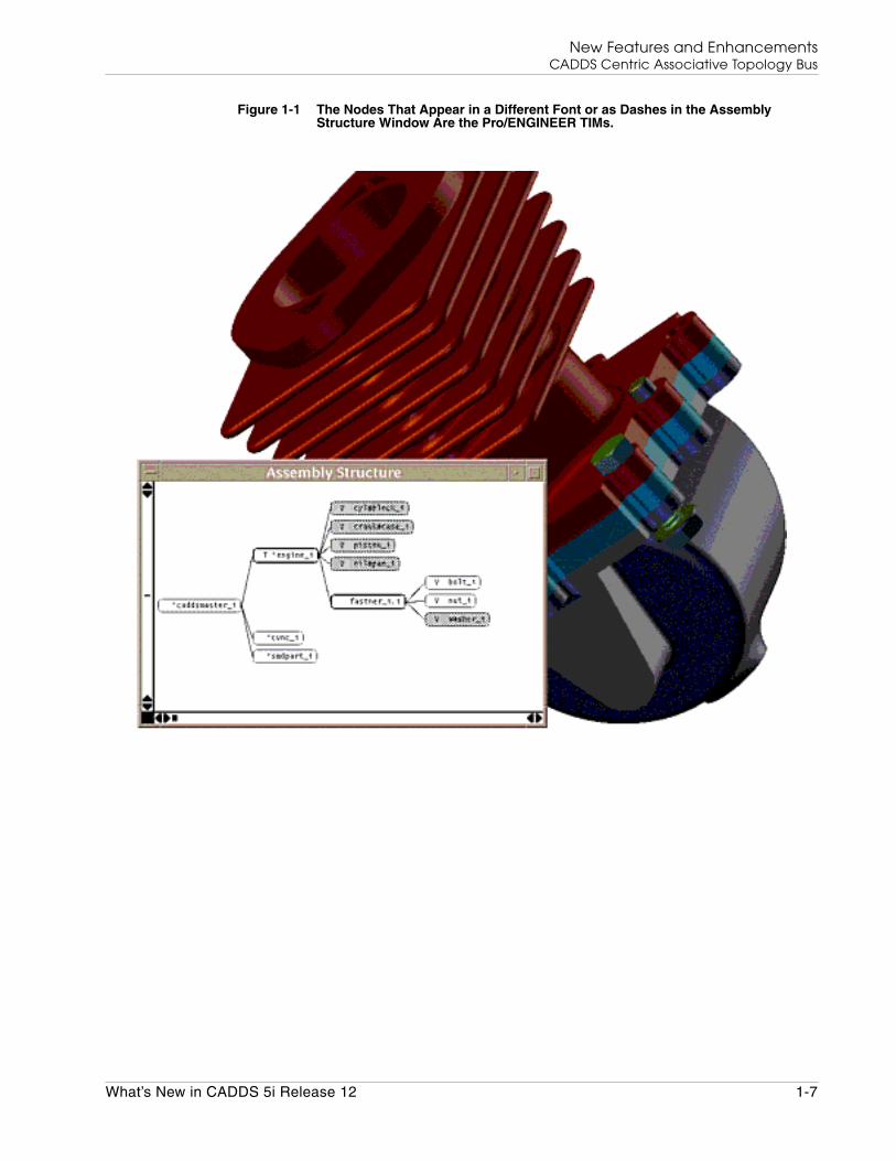
Associative Topology Bus (ATB) provides both CADDS and Pro/ENGINEERusers with a heterogeneous environment where both CADDS and Pro/ENGINEERmodels can be used for modeling and assembly work in a single CADenvironment.
You can now import Pro/ENGINEER parts and assemblies into CADDS formatfrom the CADDS environment. You can also export CADDS parts and assembliesinto Pro/ENGINEER format from the CADDS environment. You can then use theexported CADDS parts and assemblies in Pro/ENGINEER.
The ATB functionality is available through the CADDS desktop or the LDM in theParts mode, Assembly mode, and also from the Assembly Structure Window. TheATB functionality is also available through the CADDS command line interface inthe Explicit, Parametric, and Assembly environments of CADDS.
The functionality is also available through the NAV-CAMU mode of EPD EnabledCADDS 5i.
You can perform the following tasks:
• Import a Pro/ENGINEER part or assembly to CADDS thereby creating aCADDS TIM (Translated Image Model) part or assembly.
• Export a CADDS part or assembly to Pro/ENGINEER thereby creating aPro/ENGINEER TIM part or assembly.
• Verify, and if found to be out of date, update the imported CADDS TIM part orassembly.
• Verify the exported Pro/ENGINEER TIM part or assembly and, if found to beout of date, update it.
• Perform associative updates of CADDS or Pro/ENGINEER parts andassemblies. If you add parametric geometry or application data to a CADDSTIM part, and the application data references the imported geometry, theparametric geometry or application data is updated associatively to reflect thechanges in the original geometry.
See Using Associative Topology Bus Enabled CADDS 5i for details.
1-6 What’s New in CADDS 5i Release 12
New Features and EnhancementsCADDS Centric Associative Topology Bus
Figure 1-1 The Nodes That Appear in a Different Font or as Dashes in the AssemblyStructure Window Are the Pro/ENGINEER TIMs.
What’s New in CADDS 5i Release 12 1-7
New Features and EnhancementsThe DXF Converter
The DXF Converter
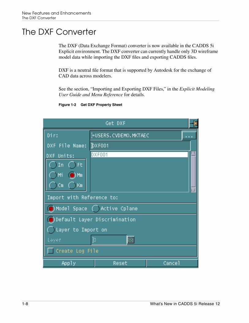
The DXF (Data Exchange Format) converter is now available in the CADDS 5iExplicit environment. The DXF converter can currently handle only 3D wireframemodel data while importing the DXF files and exporting CADDS files.
DXF is a neutral file format that is supported by Autodesk for the exchange ofCAD data across modelers.
See the section, “Importing and Exporting DXF Files,” in the Explicit ModelingUser Guide and Menu Reference for details.
Figure 1-2 Get DXF Property Sheet
1-8 What’s New in CADDS 5i Release 12

New Features and EnhancementsParametric Modeling
Parametric Modeling
The following sections describe enhancements in modeling in the Parametricenvironment.
Update Ppart
If you remove commands from the source part, the corresponding geometry fromthe target part is removed, even if it has downstream users in the target part. Theinserted part is in synchronization with the source part. If the imported geometryhas a dependent geometry, using the UPDATE PPART command results inregeneration failure.
See the section, “Update Parametric Part,” in the Parametric Modeling User Guideand Menu Reference for details.
Edit Ppart
You can now preserve the tag names of the imported parametric or explicit entitiesfrom the replaced source part using the NEW PART option of the EDIT PPARTcommand. The tag names of only those entities of the replaced source part arepreserved that match the entities of the original source part.
Please note: Use the COPYTAG option of the INSERT PPART command toimport the replaced source part entities. Using this option will preserve the entitytag names of the replaced source part.
See the section, “Edit Parametric Part,” in the Parametric Modeling User Guideand Menu Reference for details.
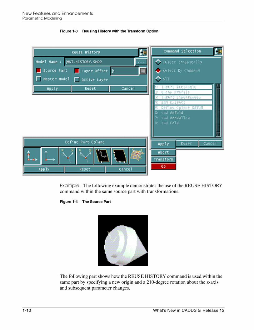
Reuse History
You can now orient the copied geometry by applying geometrical transformationsusing the REUSE HISTORY command. The transformation supports thetranslation and rotation of the copied geometry about any axis that you specify.Use the Layer option to place the copied geometry on a layer of your choice. Youcan also import geometry that is associated with the SMD application data usingREUSE HISTORY.
What’s New in CADDS 5i Release 12 1-9
New Features and EnhancementsParametric Modeling
Figure 1-3 Reusing History with the Transform Option
Example: The following example demonstrates the use of the REUSE HISTORYcommand within the same source part with transformations.
Figure 1-4 The Source Part
The following part shows how the REUSE HISTORY command is used within thesame part by specifying a new origin and a 210-degree rotation about the z-axisand subsequent parameter changes.
1-10 What’s New in CADDS 5i Release 12

New Features and EnhancementsParametric Modeling
Figure 1-5 Copied Geometry Within the Source Part with Transformations
See the section, “Copying Part History,” in the Parametric Modeling User Guideand Menu Reference for details.
Performing History Operation Using Unified HistoryMenu
The History Operations property sheet is now introduced to simplify theperformance of history operations. You can select commands from a runtime list ofthe part history commands and perform the required action using the commandsyou have selected.
What’s New in CADDS 5i Release 12 1-11

New Features and EnhancementsParametric Modeling
Figure 1-6 The History Operations Property Sheet
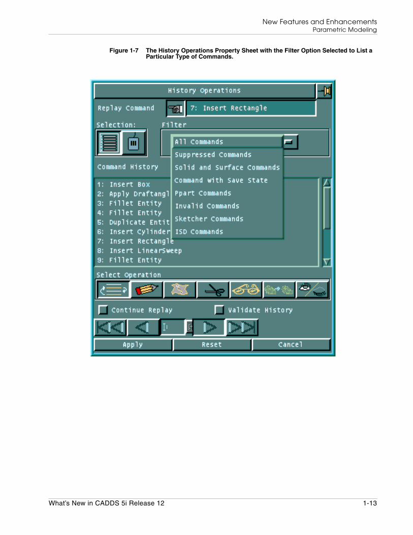
Based on the selection of commands from the runtime list of the part historycommands, you can select the operation on the History Operations property sheet.Operations that are not relevant to the selected commands are not available on theHistory Operations property sheet.
For example, if you select a command that is not of type Apply Sketch, then theEdit Sketch and Replace Sketch operations are not available on the HistoryOperations property sheet.
1-12 What’s New in CADDS 5i Release 12
New Features and EnhancementsParametric Modeling
Figure 1-7 The History Operations Property Sheet with the Filter Option Selected to List aParticular Type of Commands.
What’s New in CADDS 5i Release 12 1-13

New Features and EnhancementsParametric Modeling
Figure 1-8 The History Operations Property Sheet Shows All Commands in the RuntimeList. The Finger Points to the Current Replayed Command.
1-14 What’s New in CADDS 5i Release 12
New Features and EnhancementsParametric Modeling
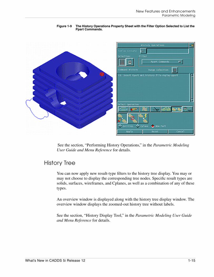
Figure 1-9 The History Operations Property Sheet with the Filter Option Selected to List thePpart Commands.
See the section, “Performing History Operations,” in the Parametric ModelingUser Guide and Menu Reference for details.
History Tree
You can now apply new result-type filters to the history tree display. You may ormay not choose to display the corresponding tree nodes. Specific result types aresolids, surfaces, wireframes, and Cplanes, as well as a combination of any of thesetypes.
An overview window is displayed along with the history tree display window. Theoverview window displays the zoomed-out history tree without labels.
See the section, “History Display Tool,” in the Parametric Modeling User Guideand Menu Reference for details.
What’s New in CADDS 5i Release 12 1-15

New Features and EnhancementsParametric Modeling
Figure 1-10 The History Tree for Part Showing the Additional Overview Display. SketchNodes from Part History are Not Shown.
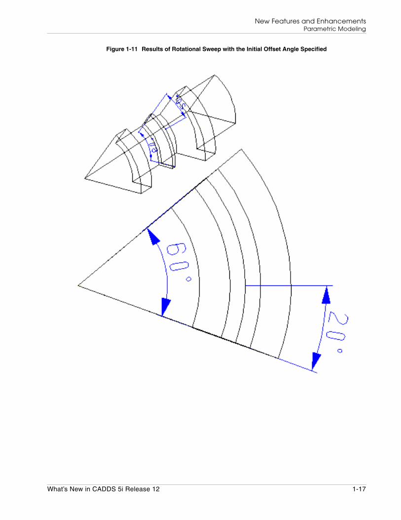
Sweeping a Face with Initial Offset Angle
You can sweep a profile or a face with an initial offset angle using the newOFFSET ANGLE option of the INSERT ROTATIONALSWEEP command.
To perform a rotational sweep between any start and end angles, specify the totalsweep and the initial offset angles.
See the section, “Conducting Sweep Operations,” in the Parametric ModelingUser Guide and Menu Reference for details.
1-16 What’s New in CADDS 5i Release 12
New Features and EnhancementsParametric Modeling
Figure 1-11 Results of Rotational Sweep with the Initial Offset Angle Specified
What’s New in CADDS 5i Release 12 1-17

New Features and EnhancementsPlotting
Plotting
The following sections describe enhancements in plotting in both environments ofCADDS.
Plotting the Raster Output
The PLOT DOT command is enhanced to support alternative raster output formatssuch as GIF and JPEG. The new GIF option produces raster output in the GIF87format. The new JPEG option produces raster output in the JPEG format.
You can view these GIF and JPEG files using any raster file image viewer. You canalso specify the plotter settings for the raster output.
Figure 1-12 The Plot Dot Property Sheet with the GIF Option Selected
See the Explicit Modeling User Guide and Menu Reference and the ParametricModeling User Guide and Menu Reference for details.
1-18 What’s New in CADDS 5i Release 12

New Features and EnhancementsPlotting
Plotting the History Tree and the Assembly Structure
You can now plot the history tree of an active part or the assembly structure of anactive assembly to a disk file or a plotter using the new PLOT TREE command.
• Use PLOT TREE HISTORY to plot the history tree in the Parametricenvironment.
• Use PLOT TREE ASSEMBLY to plot the assembly structure in the Assemblyenvironment.
You can choose to plot a node of a history tree or the assembly structure alongwith its dependent nodes.
See the Concurrent Assembly Mock-Up User Guide and Menu Reference, theParametric Multipart Design User Guide and Menu Reference, and the ParametricModeling User Guide and Menu Reference for details.
What’s New in CADDS 5i Release 12 1-19
New Features and EnhancementsDrafting and Dimensioning
Drafting and Dimensioning
The following sections describe enhancements in Context Sensitive Dimensioning(CSD). See the Design and Drafting User Guide and Menu Reference for details.
Enhancements in CSD
CSD now allows you to perform the following tasks:
• Track the primary and secondary tolerances automatically.
For example, if you add a primary tolerance value, the tolerance value isautomatically converted to a rounded secondary tolerance value and is thenstored in a stack.
• Modify the Feature Control Symbols (FCS) that are created in the ANSI andISO standards without exiting the CSD environment.
• Store the information on intersecting dimensions.
This information is useful if you have a dimension that has been created usingintersection points.You can use the intersection information to modify theentities that are selected for intersection. The intersection points are thenrecalculated and the dimension changed accordingly.
• Align multiple dimensions simultaneously in the Modify Dimensions mode.
Only dimensions that belong to the same type of entities are selected foralignment and grouping.
• Group together a set of dimensions.
You can also drag the group of dimensions and break a dimension from thegroup.
Aligning Dimensions
You can align two or more dimensions simultaneously.
Aligning Two Dimensions
Move the cursor over a dimension and select it using the select mouse button. Thedimension is highlighted. Select another dimension similarly. The two dimensionsare automatically aligned when you release the mouse button.
Please note: Do not move the mouse after you select the dimensions.
1-20 What’s New in CADDS 5i Release 12
New Features and EnhancementsDrafting and Dimensioning
Aligning Multiple Dimensions
When aligning multiple dimensions, ensure that you select dimensions that belongto a similar type of entity.
By Selecting Entities: The dimensions you select must belong to one of thefollowing categories:
• Horizontal
• Vertical
• Point-to-point
• Angular
Select multiple dimensions by holding down the Shift key and clicking the selectmouse button on the dimension entities. Release the Shift key only after youhave selected all the entities. The dimensions are automatically aligned with thedimension of the first entity that you selected.
Please note: Keep the mouse very still when selecting the entity with theselect mouse button. Otherwise, the action is registered as a drag operation insteadof a selection.
By Selecting Entities in a Window: Select the dimensions that requirealignment in a crossing window. Move the mouse with the select button and theShift key pressed to create the crossing window.
Defining a Group of Dimensions
You can group together a set of dimensions that are not aligned. Select a dimensionas the reference using the first mouse button. Press the g key. With the selectmouse button pressed, drag the mouse to select the dimensions that are not alignedin a crossing window. The dimensions within the crossing window form a group.
Dragging the Group of Dimensions
Hold down the Shift key and move the mouse to drag the selected group ofdimensions. Release the Shift key. Press the Shift key again to drag the nextgroup of dimensions.
Breaking a Dimension from the Group
Select a dimension and drag the dimension away from the group without holdingdown the Shift key to break the dimension from the group.
What’s New in CADDS 5i Release 12 1-21
New Features and EnhancementsDrafting and Dimensioning
Using Dimension Update Management
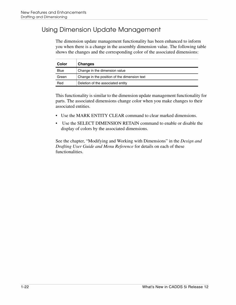
The dimension update management functionality has been enhanced to informyou when there is a change in the assembly dimension value. The following tableshows the changes and the corresponding color of the associated dimensions:
This functionality is similar to the dimension update management functionality forparts. The associated dimensions change color when you make changes to theirassociated entities.
• Use the MARK ENTITY CLEAR command to clear marked dimensions.
• Use the SELECT DIMENSION RETAIN command to enable or disable thedisplay of colors by the associated dimensions.
See the chapter, “Modifying and Working with Dimensions” in the Design andDrafting User Guide and Menu Reference for details on each of thesefunctionalities.
Color Changes
Blue Change in the dimension value
Green Change in the position of the dimension text
Red Deletion of the associated entity
1-22 What’s New in CADDS 5i Release 12

New Features and EnhancementsHidden Line Removal
Hidden Line Removal
You can now further refine the Hidden Line Removal (HLR) operation bychoosing a combination of any of the following options in the Assembly modeapart from the Part mode:
• Quality
• Selection Method
• Image Details
After selecting an option, additional options are available within that option. TheRemove Hidden Lines property sheet changes according to the combination ofoptions that you select.
For example, if you select the Faceted option, and then select the Quality option,the Remove Hidden Lines property sheet appears.
Figure 1-13 Remove Hidden Lines Property Sheet with the Quality Options
You can also perform the hidden line removal operation without selecting theQuality, Selection Method, and Image Details options. The hidden lines areremoved using the default values of these options.
What’s New in CADDS 5i Release 12 1-23

New Features and EnhancementsHidden Line Removal
See the section, “Removing Hidden Lines,” in the Hidden Line Removal (and AECHLR) User Guide and Menu Reference for details.
Figure 1-14 Hidden Lines Removal Operation on an Assembly
1-24 What’s New in CADDS 5i Release 12
New Features and EnhancementsIntegrated 3D Sketcher
Integrated 3D Sketcher
The following sections describe enhancements in Sketcher. These enhancementsare provided with an intent to allow the migration of DesignView functionality toSketcher.
See the Integrated 3D Sketcher Menu and Technical Reference for details on eachof these enhancements.
Importing DesignView Profiles
You can now import DesignView profiles into Sketcher. The new DesignViewoption in the Open Sketch menu displays a runtime list of all the DesignViewprofiles. When you select a .dv file from the runtime list, a sketch of theDesignView profile is created and saved with the same name and equivalentSketcher geometry. You can then save this sketch profile under a new name usingFile Sketch w/Options from the resultant File menu.
Angular dimensions, text and preview information, crosshatches, variables, andequations related to DesignView geometry are not imported into Sketcher.
Fillets and chamfers are imported as arcs and lines, respectively. You cannotimport construction entities and geometric constraints. However, you can importthe point-on-curve constraint and infer horizontal and vertical constraints.
Importing Explicit Geometry Directly
You can now import explicit geometry into Sketcher, facilitating the import ofIGES or DXF data into Sketcher through the Explicit environment. The importedgeometry has no model association, unlike the import of parametric geometry.
Defining a Cplane in Sketcher
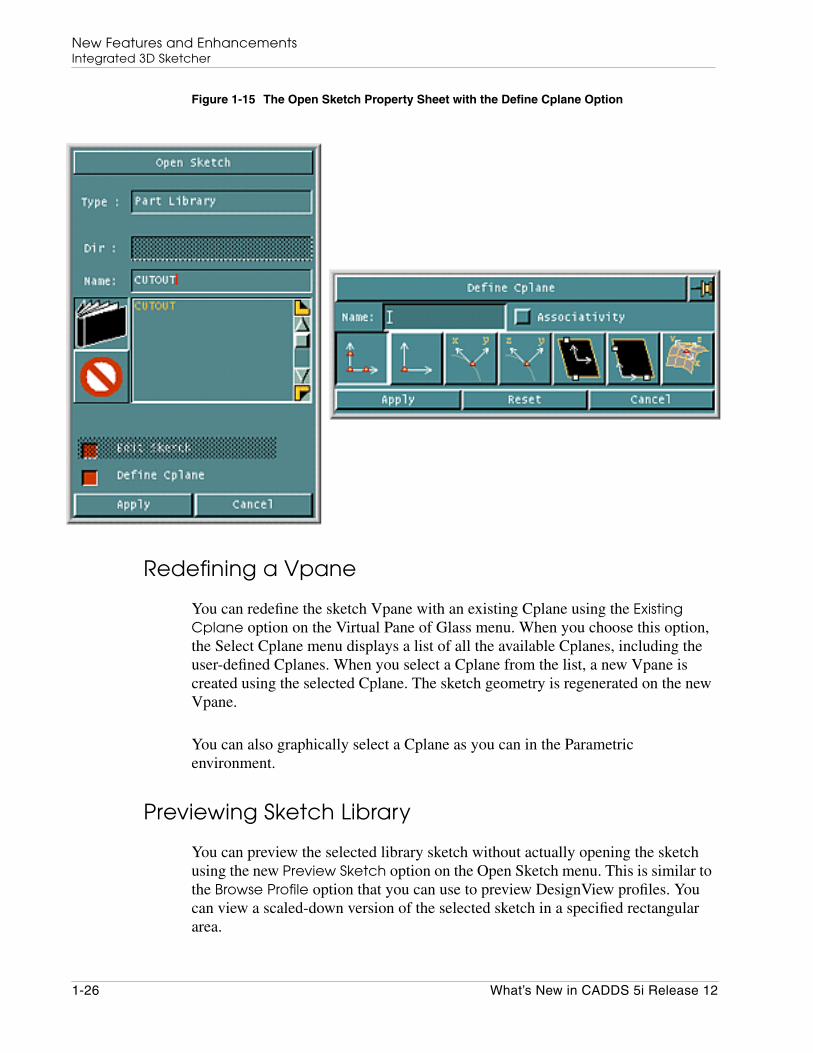
The Open Sketch menu is now available with a new Define Cplane option that isvalid only for new sketches and not for applied sketches. The Cplane that youdefine is the active Cplane and is used to define the Vpane.
What’s New in CADDS 5i Release 12 1-25
New Features and EnhancementsIntegrated 3D Sketcher
Figure 1-15 The Open Sketch Property Sheet with the Define Cplane Option
Redefining a Vpane
You can redefine the sketch Vpane with an existing Cplane using the ExistingCplane option on the Virtual Pane of Glass menu. When you choose this option,the Select Cplane menu displays a list of all the available Cplanes, including theuser-defined Cplanes. When you select a Cplane from the list, a new Vpane iscreated using the selected Cplane. The sketch geometry is regenerated on the newVpane.
You can also graphically select a Cplane as you can in the Parametricenvironment.
Previewing Sketch Library
You can preview the selected library sketch without actually opening the sketchusing the new Preview Sketch option on the Open Sketch menu. This is similar tothe Browse Profile option that you can use to preview DesignView profiles. Youcan view a scaled-down version of the selected sketch in a specified rectangulararea.
1-26 What’s New in CADDS 5i Release 12

New Features and EnhancementsIntegrated 3D Sketcher
Figure 1-16 Preview of the Scaled-Down Version of the Selected Library Sketch in aSpecified Rectangular Area
Editing and Applying Sketches
You can now apply the sketch geometry as elementary curves using the optionApply and Exit Sketch w/Options on the File Sketch menu.
What’s New in CADDS 5i Release 12 1-27
New Features and EnhancementsIntegrated 3D Sketcher
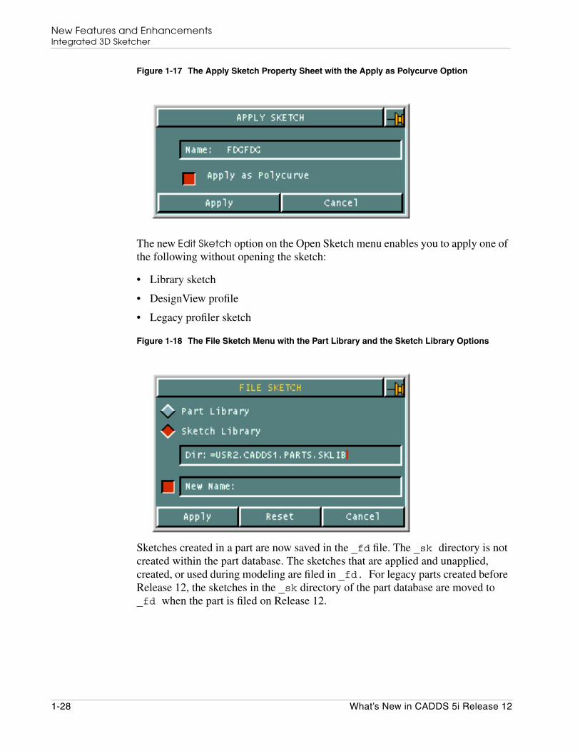
Figure 1-17 The Apply Sketch Property Sheet with the Apply as Polycurve Option
The new Edit Sketch option on the Open Sketch menu enables you to apply one ofthe following without opening the sketch:
• Library sketch
• DesignView profile
• Legacy profiler sketch
Figure 1-18 The File Sketch Menu with the Part Library and the Sketch Library Options
Sketches created in a part are now saved in the _fd file. The _sk directory is notcreated within the part database. The sketches that are applied and unapplied,created, or used during modeling are filed in _fd. For legacy parts created beforeRelease 12, the sketches in the _sk directory of the part database are moved to_fd when the part is filed on Release 12.
1-28 What’s New in CADDS 5i Release 12
New Features and EnhancementsIntegrated 3D Sketcher
Ascertaining Status of Geometry
A new Solver Status option in the Environment globals area reflects the currentstatus of the sketch geometry. The geometry appears red if it is underconstrainedand green when fully constrained.
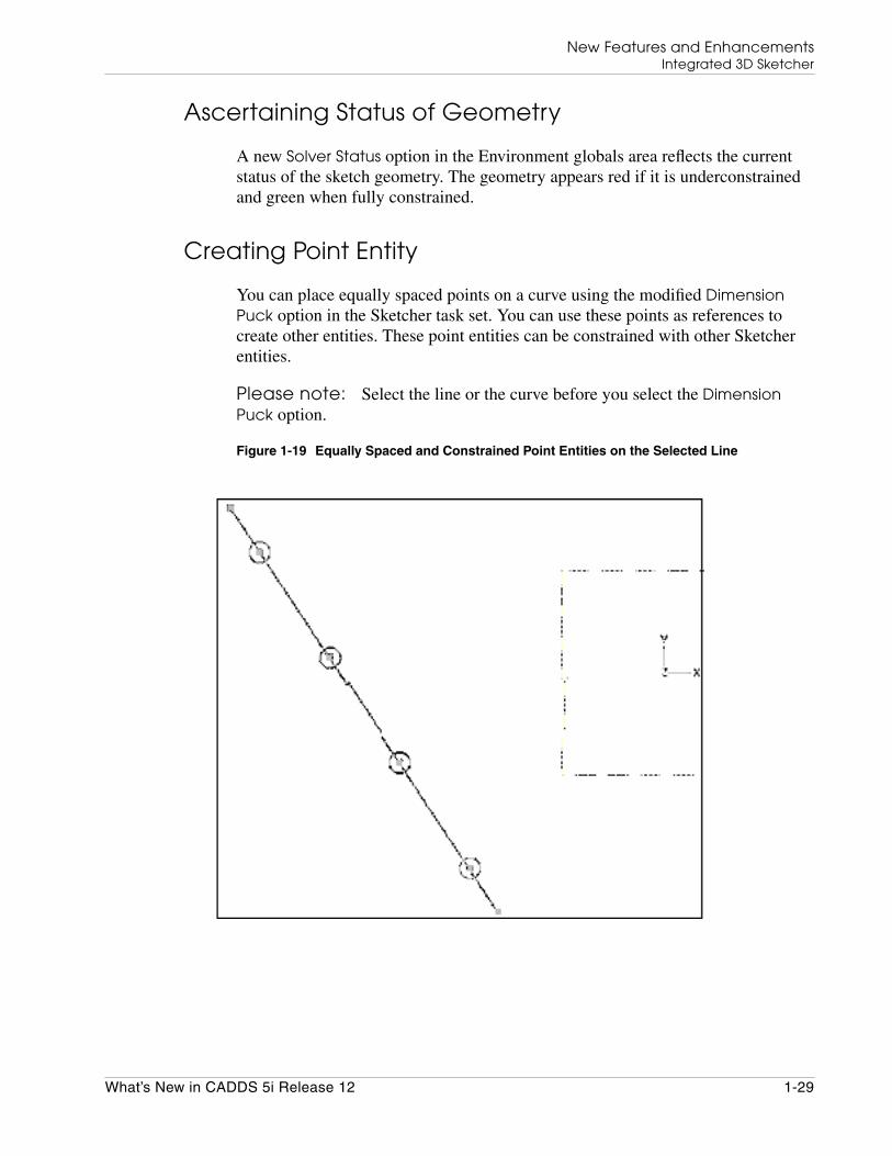
Creating Point Entity
You can place equally spaced points on a curve using the modified DimensionPuck option in the Sketcher task set. You can use these points as references tocreate other entities. These point entities can be constrained with other Sketcherentities.
Please note: Select the line or the curve before you select the DimensionPuck option.
Figure 1-19 Equally Spaced and Constrained Point Entities on the Selected Line
What’s New in CADDS 5i Release 12 1-29

New Features and EnhancementsIntegrated 3D Sketcher
Figure 1-20 Equally Spaced Point Entities on a Selected Arc and a Line
You can also create standalone point objects. Use the Construction Entity optionto select either a point object or a dimension puck.
Mirroring and Sewing Functions
Assist lines for mirroring and sewing are now enhanced. Alert windows are nowdisplayed if you do not select entities for mirroring or sewing.
Figure 1-21 Alert Window Prompting You to Select the Entities for Mirroring
You can now select a continuous loop of entities for sewing using the parametricCHAIN option from the Selection area of the top bar.
1-30 What’s New in CADDS 5i Release 12
New Features and EnhancementsIntegrated 3D Sketcher
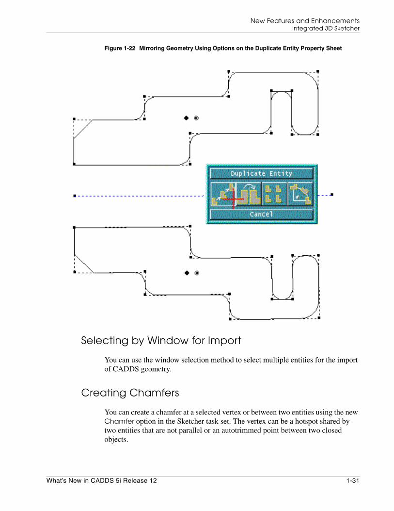
Figure 1-22 Mirroring Geometry Using Options on the Duplicate Entity Property Sheet
Selecting by Window for Import
You can use the window selection method to select multiple entities for the importof CADDS geometry.
Creating Chamfers
You can create a chamfer at a selected vertex or between two entities using the newChamfer option in the Sketcher task set. The vertex can be a hotspot shared bytwo entities that are not parallel or an autotrimmed point between two closedobjects.
What’s New in CADDS 5i Release 12 1-31

New Features and EnhancementsIntegrated 3D Sketcher
Figure 1-23 A Vertex Chamfer
Figure 1-24 A Chamfer Between Two Entities at a Specific Angle
1-32 What’s New in CADDS 5i Release 12
New Features and EnhancementsIntegrated 3D Sketcher
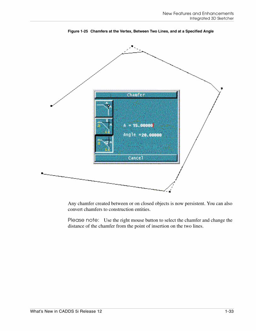
Figure 1-25 Chamfers at the Vertex, Between Two Lines, and at a Specified Angle
Any chamfer created between or on closed objects is now persistent. You can alsoconvert chamfers to construction entities.
Please note: Use the right mouse button to select the chamfer and change thedistance of the chamfer from the point of insertion on the two lines.
What’s New in CADDS 5i Release 12 1-33

New Features and EnhancementsIntegrated 3D Sketcher
Filleting
In addition to creating a vertex fillet, you can now create two-entity andthree-entity fillets in Sketcher as in the Parametric environment. The Fillet optionin the Sketcher task set now includes the following options:
• Two-Entity Fillet
• Three-Entity Fillet
Figure 1-26 Two-Entity and Three-Entity Fillets
1-34 What’s New in CADDS 5i Release 12
New Features and EnhancementsIntegrated 3D Sketcher
Any fillet created between closed objects is now persistent. You can convert filletsto construction entities and add the equal radius constraint to them.
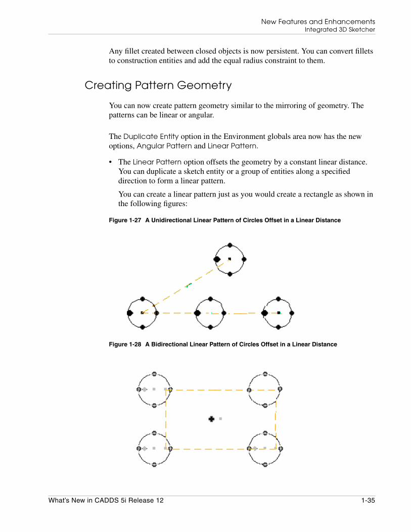
Creating Pattern Geometry
You can now create pattern geometry similar to the mirroring of geometry. Thepatterns can be linear or angular.
The Duplicate Entity option in the Environment globals area now has the newoptions, Angular Pattern and Linear Pattern.
• The Linear Pattern option offsets the geometry by a constant linear distance.You can duplicate a sketch entity or a group of entities along a specifieddirection to form a linear pattern.
You can create a linear pattern just as you would create a rectangle as shown inthe following figures:
Figure 1-27 A Unidirectional Linear Pattern of Circles Offset in a Linear Distance
Figure 1-28 A Bidirectional Linear Pattern of Circles Offset in a Linear Distance
What’s New in CADDS 5i Release 12 1-35

New Features and EnhancementsIntegrated 3D Sketcher
Figure 1-29 A Rectangle Duplicated and Offset by Constant Linear Distance
1-36 What’s New in CADDS 5i Release 12

New Features and EnhancementsIntegrated 3D Sketcher
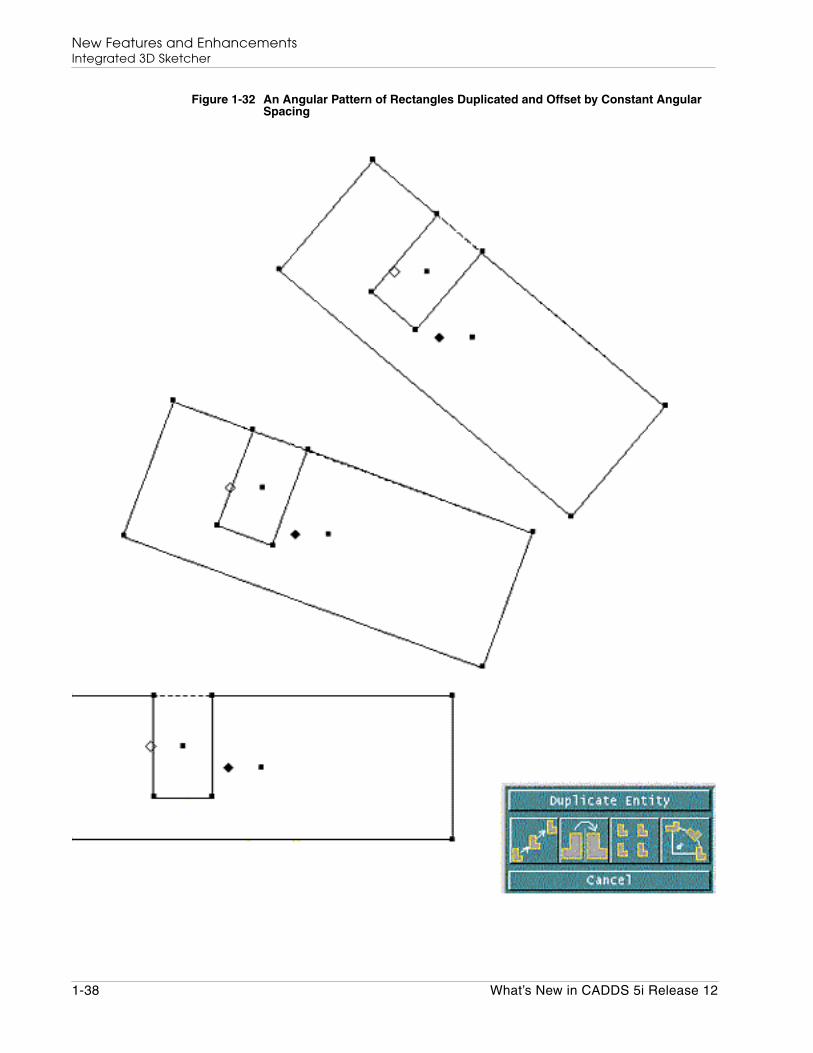
• The Angular Pattern option offsets the geometry by a constant angularspacing. You can duplicate a sketch entity or a group of entities to form acircular pattern with a specified angular spacing. The created pattern isassociative by default. The copies of the sketch entities are equally spaced on apitch circle. You can create an angular pattern just as you would create an arc asshown in the following figure:
Figure 1-30 An Angular Pattern of Circles Offset by Constant Angular Spacing
Figure 1-31 A Circular Pattern of Circles Offset by Constant Angular Spacing
What’s New in CADDS 5i Release 12 1-37
New Features and EnhancementsIntegrated 3D Sketcher
Figure 1-32 An Angular Pattern of Rectangles Duplicated and Offset by Constant AngularSpacing
1-38 What’s New in CADDS 5i Release 12

New Features and EnhancementsIntegrated 3D Sketcher
Perform either one of the following operations to break the pattern associativity:
• Remove the label
• Delete the construction entity
Creating Offsets and Thin Walls
The Sketcher task set has the Offset option. You can offset profiles and createthin-walled objects. You can select an object and offset it to a specified distance bydefault.
Figure 1-33 A Thin-Walled Object Offset on One Side and Closed by Arcs
Figure 1-34 A Thin-Walled Object Offset on Both Sides and Closed by Arcs
Use the Thin Wall option to create a thin-walled object or derive a closed object byoffsetting the object. The distance by which the object is offset is the thickness thatis created. You can close the ends by specifying lines or bisecting arcs.
What’s New in CADDS 5i Release 12 1-39
New Features and EnhancementsIntegrated 3D Sketcher
Using New Environment Menu Options
The Environment menu now allows you to change the default color settings fordimensions and constraints. You can also change the highlight colors and colorsettings for construction entities, guidelines, model references, and hotspots.
• The Snap to Geometry option allows you to snap to the existing geometryand guidelines.
• The Marker Scale Factor option allows you to control the size of the hotspotand constraint graphics, object handles, and reference points.
• The Snap Range option allows you to set the snap range to a small, medium,or large value so that you can avoid snapping to entities that are not required.
• The Color Setup option allows you to change the color of the sketch.
You can set the default values for the environment variables in a file called.cadds5sketch in your home directory. You can then change the settings duringa Sketcher session.
Using Other Parametric Options in Sketcher
The following parametric options are now available in Sketcher:
• The Selection Setup option allows you to change the colors of the selectedsketch entities. Access this option through the SETUP option on the top bar.
• The Parameter Setup menu allows you to change the color of the parameters,dimensions, and constraint graphics.
• The Display Attribute Setup option allows you to change the color and font ofthe construction entity. Access this option through the CONSTRUCT option ofthe SETUP menu.
Grid changes are now persistent across Sketcher and Parametric environments.
1-40 What’s New in CADDS 5i Release 12
New Features and EnhancementsInteractive Surface Design
Interactive Surface Design
The following sections describe enhancements in Interactive Surface Design(ISD).
See the Interactive Surface Design Menu and Technical Reference for details oneach of these functionalities.
Geometric Loft
New geometric lofts in ISD follow.
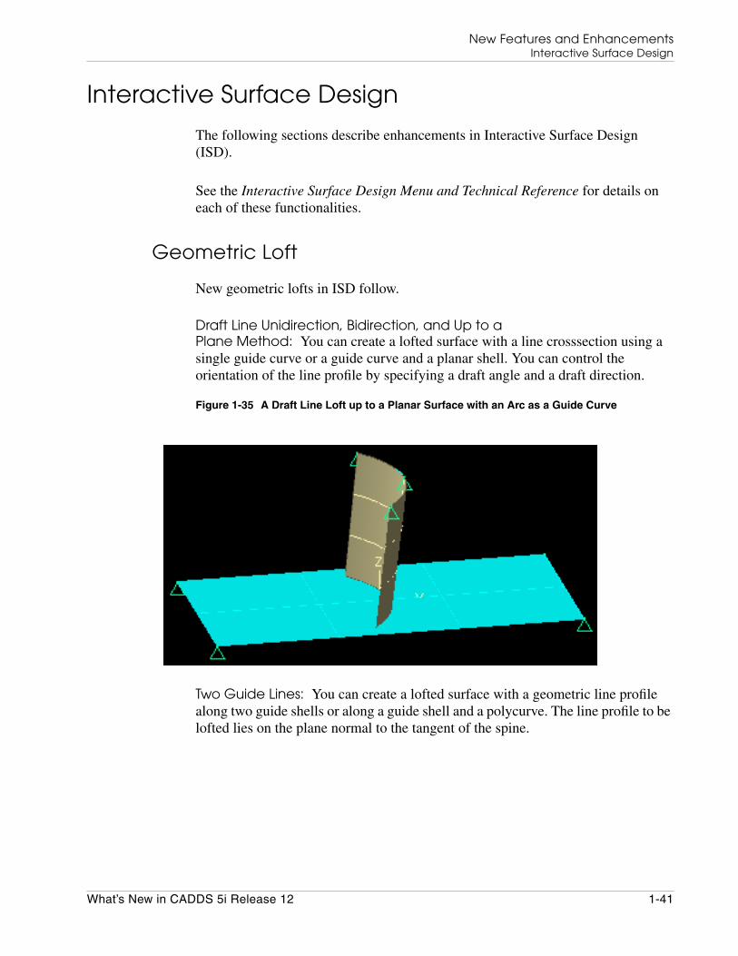
Draft Line Unidirection, Bidirection, and Up to aPlane Method: You can create a lofted surface with a line crosssection using asingle guide curve or a guide curve and a planar shell. You can control theorientation of the line profile by specifying a draft angle and a draft direction.
Figure 1-35 A Draft Line Loft up to a Planar Surface with an Arc as a Guide Curve
Two Guide Lines: You can create a lofted surface with a geometric line profilealong two guide shells or along a guide shell and a polycurve. The line profile to belofted lies on the plane normal to the tangent of the spine.
What’s New in CADDS 5i Release 12 1-41
New Features and EnhancementsInteractive Surface Design
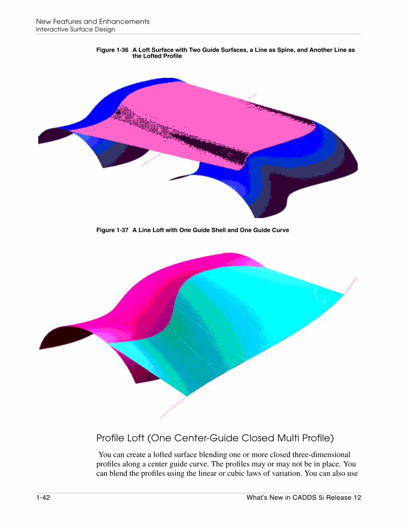
Figure 1-36 A Loft Surface with Two Guide Surfaces, a Line as Spine, and Another Line asthe Lofted Profile
Figure 1-37 A Line Loft with One Guide Shell and One Guide Curve
Profile Loft (One Center-Guide Closed Multi Profile)
You can create a lofted surface blending one or more closed three-dimensionalprofiles along a center guide curve. The profiles may or may not be in place. Youcan blend the profiles using the linear or cubic laws of variation. You can also use
1-42 What’s New in CADDS 5i Release 12

New Features and EnhancementsInteractive Surface Design
the law of variation to modify the cross-sectional area of the lofted surface.Thevalue of the law of variation can vary between 0.0 and 1.0.
Tangency Constraints on a Lofted Surface
You can interactively select a vector field attached to the first or the last guidecurve or both, and use it to constrain the lofted surface. Constraining a loftedsurface using a vector field depends on the type of the lofted surface and thenumber of guides. The constraint on the lofted surface is defined by the normaldirection of the tangent vector field. Any change in the magnitude of the vectorfield does not affect the shape of the resultant lofted surface.
Figure 1-38 Results of the Conic Rho Loft with the Guides as Curves on Surfaces withVector Field Tangency Constraints Applied
What’s New in CADDS 5i Release 12 1-43
New Features and EnhancementsInteractive Surface Design
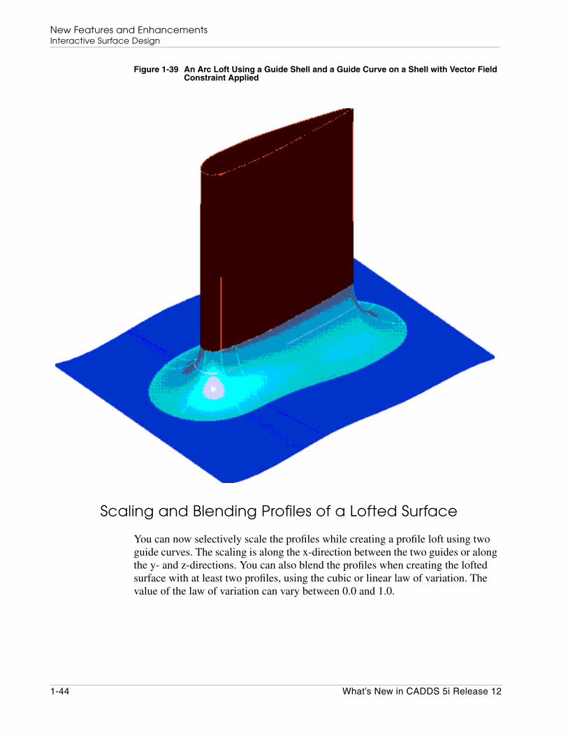
Figure 1-39 An Arc Loft Using a Guide Shell and a Guide Curve on a Shell with Vector FieldConstraint Applied
Scaling and Blending Profiles of a Lofted Surface
You can now selectively scale the profiles while creating a profile loft using twoguide curves. The scaling is along the x-direction between the two guides or alongthe y- and z-directions. You can also blend the profiles when creating the loftedsurface with at least two profiles, using the cubic or linear law of variation. Thevalue of the law of variation can vary between 0.0 and 1.0.
1-44 What’s New in CADDS 5i Release 12
New Features and EnhancementsInteractive Surface Design
Break at Curvature Discontinuity
You can divide a lofted surface at the joints of a guide polycurve that has curvaturediscontinuity to better approximate the lofted surface.
Creation of Construction Planes
You can define various Cplanes within ISD to create geometry in a moreconvenient and flexible manner. Modifying a Cplane updates the geometry createdin that Cplane and the corresponding model tree. You can also rotate the Cplaneabout any axis.
Selection of Entities
You can now use the selection options available from the Selection area of theCADDS desktop in ISD. You can select entities using different methods such asindividual selection, selection by a given name, attribute, layer, and group, or bydefining window borders. You can also use filters for selection.
Filleting
You can now create a fillet between two planar or nonplanar multisegmentpolycurves or surface curves. The fillet between the two multisegment polycurvesis tangent to both the polycurves. For planar polycurves, the fillet is in the sameplane on which the polycurves are coplanar. The fillet between nonplanarpolycurves is on the surface of a hypothetical cylinder encapsulated between thepolycurves. The axis of the fillet is perpendicular to the best fit plane for both thepolycurves and passes through the center of the fillet.
Creation of Geodesic
You can create a geodesic of a specific length in a given direction from a pton on asurface curve or on a curve lying on the surface.
What’s New in CADDS 5i Release 12 1-45

New Features and EnhancementsInteractive Surface Design
Figure 1-40 A Geodesic
Join and Divide Options
The JOIN command now allows you to modify the operand curves in theModification mode. The At Position option on the Divide Curve menu allows youto selectively add or remove the ptons at which the curve must divide.
Section Curve in Parametric History
You can create a copy of a section curve and save this new section curve in theparametric history database. A plane gets attached to this section curve. You canmodify the section curve using this plane.
Model Referencing
You can create a polygon curve with model references like End of and Mid ofusing the Coordinate menu. You can modify the data point of a dataset and thepolygon point of a polygon curve with reference to a model.
1-46 What’s New in CADDS 5i Release 12

New Features and EnhancementsInteractive Surface Design
Modifying the Surface Degree
You can now modify the u-degree and v-degree of a basic or lofted surface. Youcan also change the existing degree using the Degree option in the Constraintsmenu.
The Undo Option
With the UNDO option, you can restore a model to the state before the lastmodification.
Tag Assignment and Removal
You can now assign or remove the tag name of an ISD entity.
Pton on Polycurves
You can now create ptons on a multisegment polycurve using the Pton option fromthe task set.
Selective Shading
You can now selectively shade the faces of a shell or a shell from a view.
Dynamic Sectioning
A new option now enables dynamic sectioning in ISD. You can now create a planeon a curve pton and dynamically drag this plane along the curve. The section curveis updated simultaneously.
Global Normalized Parameter
If there is a change in the topology of a curve or a surface, ptons are now updatedand stored based on global normal parameters. This method of storage helps theregeneration of commands.
Highlight Dependency
You can now select an entity and display the dependent entities using the HighlightDependency option in the Parameter menu.
What’s New in CADDS 5i Release 12 1-47
New Features and EnhancementsInteractive Surface Design
Other Menu Enhancements
The following are additional menu enhancements:
• The Data Set Read menu is now consistent with the other ISD menus.
• The DataPoint External Constraint menu is enhanced so that the vector nolonger determines the magnitude. The vector defines the direction only andmust be specified in units in the Fillin field.
• The Smooth menu now has a new Stiffness option. Use this option to control theshape of the curve. The stiffness value is in the range from 0 to 1.
• You can now create ptons using the Int of and Mid of options in the Coordinatemenu for polycurves.
• You can now access the Utility menu in the ISD environment just as you havebeen in the Parametric environment. Right-click to access the Utility menu.
• The locking options available at pton on a curve are now consistent in behavior.
1-48 What’s New in CADDS 5i Release 12

New Features and EnhancementsConcurrent Assembly Mock-Up
Concurrent Assembly Mock-Up
The following sections describe enhancements in Concurrent Assembly Mock-Up(CAMU).
Exporting an Assembly with Associated Adrawingsand View States
When exporting an assembly, you can now choose to transfer the Adrawings andthe view states associated with the main assembly to the exported assembly.
When you export an assembly with its Adrawings, the filed view states are alsotransferred to the exported assembly.
See the section, “Creating a New Assembly by Exporting,” in the ConcurrentAssembly Mock-Up User Guide and Menu Reference for details.
Figure 1-41 The EXPORT ASSEMBLY Property Sheet
Filing an Edited or Incomplete History Replay Session
You can save an edited or incomplete history replay session of an active modelwhile activating another Adrawing or model using the FILEOPTION option of the
What’s New in CADDS 5i Release 12 1-49

New Features and EnhancementsConcurrent Assembly Mock-Up
ACTIVATE ADRAWING and ACTIVATE MODEL commands. The results arestored in the _fd.edt file of the model database. You can save or ignore the edits.
See the Concurrent Assembly Mock-Up User Guide and Menu Reference and theParametric Multipart Design User Guide and Menu Reference for details.
Performance Improvement in View Part
In the Assembly Explicit environment, when switching nodes from an Adrawingto a model or between models, only those part instances activated and suspendedare viewed off and on. Parts that are modified and filed before switching nodes arealso viewed off and on. All parts cannot be viewed off and on.
See the Concurrent Assembly Mock-Up User Guide and Menu Reference and theParametric Multipart Design User Guide and Menu Reference for details.
1-50 What’s New in CADDS 5i Release 12

New Features and EnhancementsCVNC
CVNC
The following sections describe enhancements in CVNC.
Exporting CVNC Data to Pro/NC
You can now export CVNC data to Pro/NC using the new CVNC command,EXPORT PROE. The EXPORT PROE command creates the toolpath and otherdata in a format that can be read by Pro/NC.
See the CVNC System User Guide and Menu Reference for details.
Toolpath Animation for Fastening
You can now perform the following tasks with toolpath animation:
• Display two tools and anvils with the toolpath of each tool.
• Display tools in the shaded mode.
• Dynamically manipulate the model and the tools using a mouse.
• Control the speed of animation.
See the CVNC-Fastening User Guide and Menu Reference for details.
Using the ROTATE Command
You can now transform the toolpath in 3D space from a base coordinate system toa target coordinate system using the modifiers BASESYS and TARGSYS of theROTATE command.
You can also indicate the number of times the block is to be transformedspecifying the TIMES modifier. See the CVNC System User Guide and MenuReference and the CVNC Milling Command Reference for details.
What’s New in CADDS 5i Release 12 1-51
New Features and EnhancementsCVNC
Multi-Axis Enhancements
Multi-axis enhancements in CVNC are as follows:
• The PROFILE5 and SWARFCUT commands have been enhanced to include9d block output in the CLFile and APT source files.
• The PROFILE3 and PROFILE5 commands have been enhanced to includecollision detection similar to collision detection with the SWARFCUTcommand.
• The PROFILE3 command has also been enhanced to include cuttercompensation similar to the boundary passes for the MPOCKET command.
See the CVNC-M3 User Guide, the CVNC-M5 User Guide, and the CVNC MillingCommand Reference for details.
1-52 What’s New in CADDS 5i Release 12

New Features and EnhancementsCVNC
Figure 1-42 The 3-Axis Profile Property Sheet with the New Option to Select CollisionSurfaces
What’s New in CADDS 5i Release 12 1-53

New Features and EnhancementsCVNC
Figure 1-43 Geometry Showing PROFILE3 Command Detecting Collision and Continuing
1-54 What’s New in CADDS 5i Release 12

New Features and EnhancementsCVNC
Figure 1-44 Geometry Showing PROFILE3 Command Detecting Collision and Stopping
What’s New in CADDS 5i Release 12 1-55

New Features and EnhancementsCVNC
Figure 1-45 The 5-Axis Profiling Property Sheet with the New Option to Select CollisionSurfaces or Groups
1-56 What’s New in CADDS 5i Release 12
New Features and EnhancementsCVNC
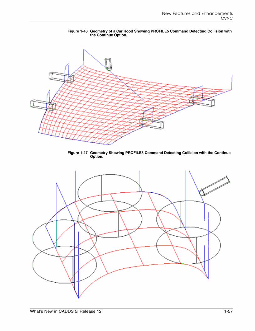
Figure 1-46 Geometry of a Car Hood Showing PROFILE5 Command Detecting Collision withthe Continue Option.
Figure 1-47 Geometry Showing PROFILE5 Command Detecting Collision with the ContinueOption.
What’s New in CADDS 5i Release 12 1-57
New Features and EnhancementsCVNC
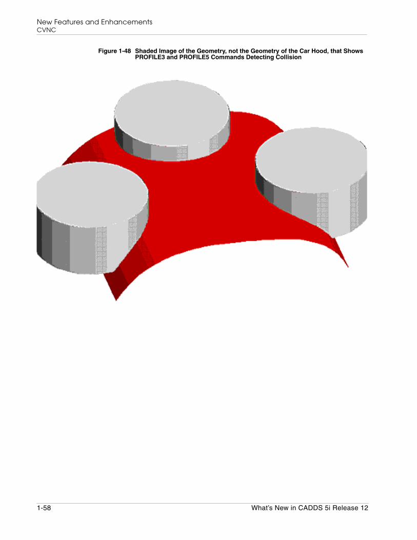
Figure 1-48 Shaded Image of the Geometry, not the Geometry of the Car Hood, that ShowsPROFILE3 and PROFILE5 Commands Detecting Collision
1-58 What’s New in CADDS 5i Release 12

New Features and EnhancementsShipbuilding (AEC)
Shipbuilding (AEC)
The following sections describe enhancements in the Advanced StructuralModeling (ASM), CV Hull, Piping, and Electrical Cabling packages of AECshipbuilding.
Advanced Structural Modeling
The following sections describe enhancements in ASM. See the AdvancedStructural Modeling User Guide and Menu Reference for details.
Classifying Structural Objects
A new Classify STobject option on the Utility palette displays a classification treethat enables you to classify structural objects. A classified structural object isrepresented by a unique line font.
Creating Endcuts
You can now specify separate symbols for the different endcut types using the newSymbol Name option on the Create Endcut Sections property sheet.
Endcut Auto Selection
You can now make a graphical selection of any end of a structural element. Youcan choose either end of an STelement without having to know which end is END1or END2. You can also select a flange or a web. The selected end is automaticallyrecognized as a flange or a web and the appropriate endcut specification is applied.
Use the new AUTO modifier in the INSERT STENDCUT and EDIT STOBJECTcommands to graphically select an end of the structural element.
What’s New in CADDS 5i Release 12 1-59

New Features and EnhancementsShipbuilding (AEC)
Figure 1-49 The End Cut/Cutout Parameters Property Sheet with the New Auto SelectionOption
Weld Material
You can define a name for the weld filler material when inserting or editing aweld. The Create Structural Weld property sheet has the additional Weld Materialoption. This option overrides the FMMATERIAL value read from the weldlibrary.
Defining Structural Panels
You can define a structural panel by selecting the plates that comprise the panelusing the new command DEFINE STPANEL.
1-60 What’s New in CADDS 5i Release 12
New Features and EnhancementsShipbuilding (AEC)
CV Hull
The following sections describe enhancements in CV Hull. See the CV HullManufacturing Commands for details.
Transverse and Longitudinal Section Drawings
In the transverse and longitudinal section drawings, you can display:
• The STobject properties using the new Annotate Property option from theCV Hull task set.
• The cutting allowance symbol and its value associated with the edges of a plate,panel, or block using the new Insert Symbol option from the CV Hull task set.
• The stiffener endcut symbols using the parameterDISPLAY-ENDCUT-SYMBOL in the nestparameter file.
• The stiffener landings in single-line or double-line font representation using theparameter STIFF-REP in the nestparameter file.
• The stiffener cross-section in single-line or double-line font representationusing the parameter STIFF-LINE-FONT in the nestparameter file.
• The plate thickness labels using the parameter PLATE-THICKNESS in thenestparameter file.
Panel Drawings
In the panel drawing, you can now display:
• The STobject properties using the new Annotate Property option.
• The cutting allowance symbol and its value associated with the edges of a plate,panel, or block using the new Insert Symbol option.
• The flange direction or the direction of the web thickness with respect to thestiffener axis using the parameter STIFF-THICK-FLAG in the nestparameterfile.
• The adjacent plates, panels and their members, that exist in the specifieddistance, and those that are related as friends with the selected panel using theSpecify Extent Distance option.
• The trace curves of different STobjects with different line fonts.
• The trace curves of plates and stiffeners without the associated weld seams.
What’s New in CADDS 5i Release 12 1-61

New Features and EnhancementsShipbuilding (AEC)
Figure 1-50 Labeling STobjects in a Panel Drawing Using the ANNOTATE PROPERTY Option
You can now manipulate the position and size of the view in a panel drawing usingthe User Defined View Boundary option on the Panel Drawing Generationproperty sheet.
Plate Drawings
In the plate drawing, you can adjust the plate geometry and distribute the weldshrinkage allowance over the marking curves parallel to the plate edge.
Stiffener Drawings
In the stiffener drawing, you can unfold the stiffener along the neutral axis to getthe exact stiffener length.
1-62 What’s New in CADDS 5i Release 12
New Features and EnhancementsShipbuilding (AEC)
Pin Jig Drawings
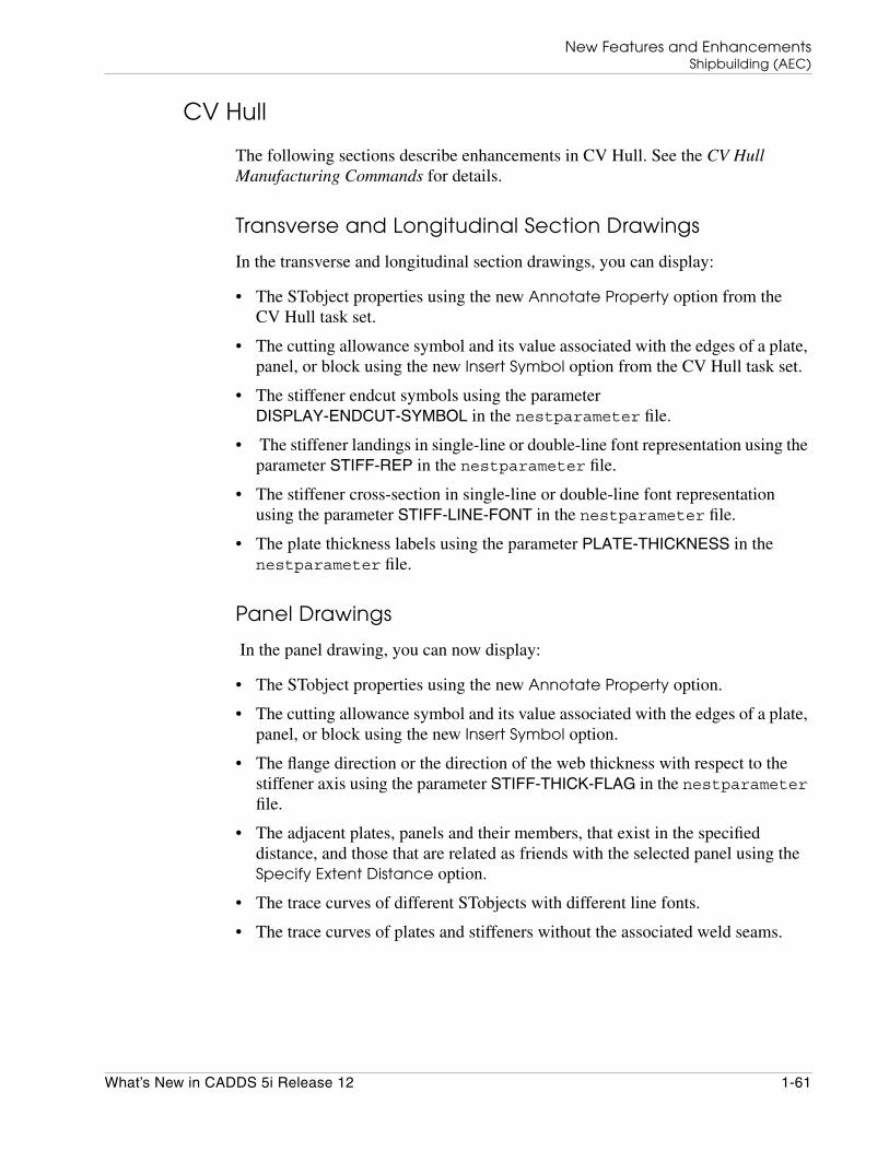
Use the new GENERATE JIGDRAW command or the GENPINJIG cvmac tocreate a pin jig drawing. You can generate the pin jig drawing using theGENERATE JIGDRAW command by default. Set the value of theAEC_PINJIG_DRAWING_BY_CVMAC environment variable to yes in the.caddsrc-local file to generate the pin jig drawing using the GENPINJIGcvmac.
Figure 1-51 Pin Jig Drawing
You can generate a jig plan for the selected structural panel or group of plates. Theoutput includes data about individual plate positioning, panel marking, panelverification, and assembly information.
Electrical Cabling Enhancements
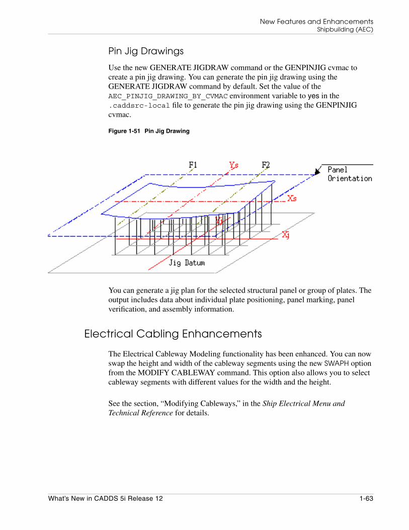
The Electrical Cableway Modeling functionality has been enhanced. You can nowswap the height and width of the cableway segments using the new SWAPH optionfrom the MODIFY CABLEWAY command. This option also allows you to selectcableway segments with different values for the width and the height.
See the section, “Modifying Cableways,” in the Ship Electrical Menu andTechnical Reference for details.
What’s New in CADDS 5i Release 12 1-63
New Features and EnhancementsShipbuilding (AEC)
Figure 1-52 Electrical Cabling Enhancement
1-64 What’s New in CADDS 5i Release 12
New Features and EnhancementsShipbuilding (AEC)
Piping Enhancements
The following sections describe piping enhancements:
Using the ROUTE PIPE Command
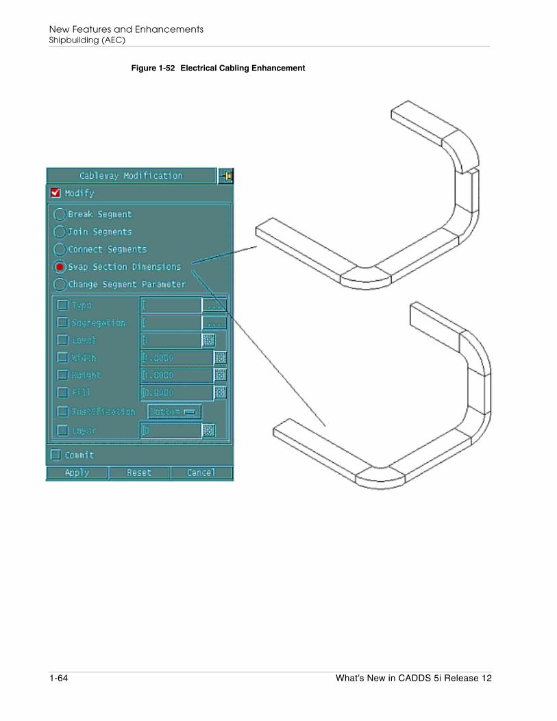
Using the enhanced ROUTE PIPE command, you can now create a branch pipelinewith a diameter different from that of the main pipeline.
You can also route a branch stubin with a different diameter using the ROUTEPIPE command. Using the BRANCH option available with the ROUTE PIPEcommand, you can route a branch pipe from an existing pipeline without using thebranch fitting at the junction of the main and branch lines.
Figure 1-53 The Route Pipe Branch Enhancement
What’s New in CADDS 5i Release 12 1-65
New Features and EnhancementsShipbuilding (AEC)
The BRANCH option has the following two options:
• BSIZE
• BSPEC
Use the BSIZE option to specify the branch and the BSPEC option to set thespecifications of the branch.
Using the ANNOTATE ISOMETRIC Command
The ANNOTATE ISOMETRIC command is now enhanced with the followingtwo options:
• SUPPRESS
• BUTTWELD
The SUPPRESS option allows you to suppress the dimension lines using theDIMENSION option or the dimension extension lines using the EXTENSION option.You can suppress dimension lines or extension lines, or both of them.
The BUTTWELD option allows you to set the dimensions for the butt-weldedfittings.
1-66 What’s New in CADDS 5i Release 12

New Features and EnhancementsShipbuilding (AEC)
Figure 1-54 The Suppression of Dimension Extension Lines
Checking Clamp Length
The Select From Selection File option is enhanced to check for the followingthree types of clamp lengths:
• Start
• Middle
• End
The clamp length is checked automatically using the values that you havespecified in the BEND_FILE and the BEND_MACHINE_FILE.
See the Piping Reference and the Piping User Guide and Menu Reference fordetails.
What’s New in CADDS 5i Release 12 1-67

New Features and EnhancementsComposites
Composites
The following sections describe enhancements in Composites Version 3.10. Seethe CADDS 5i Composites User Guide for details.
Region and Taper Definition
You can now automatically generate regions or tapers using the zones, thicknesslaw, and stagger definition. This reduces the complexity of directly definingregions and tapers.
Design 1A Enhancements
A description of enhancements in the Design 1A task set follows.
Defining Vertex Thickness
You can define the thickness for a vertex that is not connected to a region using thenew Define Vertex Thickness option available in the ThicknessLaw To ARegion property sheet. Use this option to model a part with simplified regions andtapers.
Stacking Rules Definition and Sequence Generation
The following dialog boxes have now been combined:
• Defining the Stacking Rules
• Generating a Stacking Sequence
The Generating Stacking Sequence dialog box offers the options to define thestacking rules and to generate the stacking sequence.
Using New Display Flat Allocation Menu Options
The Visual SetUp property sheet now has the following two new options:
• The Display a Particular Group option enables you to display a particulargroup with a specific orientation.
• The Display Allocation Grid option enables you to display an allocation gridwith a specific orientation.
1-68 What’s New in CADDS 5i Release 12
New Features and EnhancementsComposites
Other Enhancements
The following are additional enhancements in Composites Version 3.10:
• All dialog boxes now allow you to save or read the data files from the defaultdirectory.
• A new Cut Piece Modification dialog box now allows you to chamfer thecorners of each cut piece after flat allocation.
• You can now generate a Cutter Location Data File (CL data file) after flatallocation.
• The user interface for Draping is enhanced to rearrange the functions. TheDisplay Current Drape dialog box is now redundant and hence unavailable.
• The generation of offset surfaces is now enhanced.
• Surface allocation is now enhanced to handle complex parts.
What’s New in CADDS 5i Release 12 1-69

New Features and EnhancementsCV-DORS
CV-DORS
The new interfaces in CV-DORS allow you to perform the following tasks:
• Create and retrieve the multivalue properties of an entity.
• Create and retrieve the existing properties of a part.
• Read an entity by its tag name from the existing database.
• Access and use the entity blanking status.
See the CV-DORS User Guide for details.
1-70 What’s New in CADDS 5i Release 12

New Features and EnhancementsDatabase Command Options
Database Command Options
The following sections describe database-related enhancements. See the DatabasePolicies and Procedures for details.
validate_db
A new command line option -pt [nnn] is added to the validate_db command.It renumbers the sequence of the text nodes, starting at nnn and incrementing bythe unit of 1.
Use the -pt [nnn] option when there are invalid sequence numbers in thedatabase or when the text node sequence numbers are highly fragmented.
Report History
The validate_db command now has a new command, Report History. It reportsthe current history of the part. Part history is logged when a part database ismodified. You can create a maximum of 50 records in a history log.
The utilities that create history logs are validate_db and ckcad.
Check Dbase
A file with a .val extension is added to the ALL option of the CHECK DBASEcommand. The validation report for all entities in a part is stored in your partdirectory. The part is stored as part_name.val.
What’s New in CADDS 5i Release 12 1-71
