what's new in cimatrone 9.0 - die design - mygrowtech
TRANSCRIPT

[Type text]
What’s New in CimatronE 9.0 Progressive and Transfer Die Design
June 2009

June 2009 CimatronE 9.0 – Die Design
ii
Table of Contents
Overview ................................................................................................................................................ 1
DieQuote Generator – New Application.............................................................................................. 1 Quoting Calculation ......................................................................................................................... 1 Design Information Retrieval ........................................................................................................... 2 Customized Quoting Forms............................................................................................................. 3
Transfer Die Design – New Application .............................................................................................. 4 Blank and Process Design .............................................................................................................. 4 Die Set and Stations Layout Design................................................................................................ 5 Die Tool Design ............................................................................................................................... 6
Project and Material Setup................................................................................................................... 7 Project Setup ................................................................................................................................... 7
Setup of the Die Tool ................................................................................................................... 7 Material Setup.............................................................................................................................. 8
Material Management...................................................................................................................... 9 Material Standard and Commercial Names ................................................................................. 9 View, Edit, and Define New Material Characteristics................................................................. 10
Forming Operations............................................................................................................................ 11 Piercing Design ............................................................................................................................. 11 Skin – Overcome Sharp Corners................................................................................................... 12 Skin – New Thickness Analysis Capability .................................................................................... 13 Unfold – Automatically Ignore Freeform Details (Dimples)............................................................ 14 New L-Unbend – Unbending Sharp Corners................................................................................. 15 Unbend – K-Factor or Elongation .................................................................................................. 16 Local Blank – Region of Influence ................................................................................................. 17 Unbend of Simple Solid Model ...................................................................................................... 18
Strip Design......................................................................................................................................... 19 Cookies – Automated Function to Design Overlap between Trimming Punches (By Edges) ....... 19 Cookies – Automated Function to Design Relief at Contour’s Internal Sharp Corners (By Point). 20 Progressive Copy with Automatic Trimming.................................................................................. 21 Single Indication – Improved Editing ............................................................................................. 22

June 2009 CimatronE 9.0 – Die Design
iii
Tool Design ......................................................................................................................................... 23 Setup Parameters.......................................................................................................................... 23 Trimming Punch Improvements..................................................................................................... 24
Cut Only..................................................................................................................................... 24 Rectangular Cut ......................................................................................................................... 24 Punches with Wedges ............................................................................................................... 25
Enhanced Draft Angle Reliefs for Trimming Punches ................................................................... 26
Handling Changes .............................................................................................................................. 27 Easier Update of Geometrical Changes ........................................................................................ 27
Analysis Tools..................................................................................................................................... 28 Die Press Forces ........................................................................................................................... 28

June 2009 CimatronE 9.0 – Die Design
1
Overview
CimatronE version 9.0 delivers new functionality and improvements across the entire die making process from quoting to design and manufacturing.
In addition to the existing application for progressive die design, two new applications have been introduced: DieQuote Generator and Transfer Die Design.
New capabilities and enhancements have been added to increase automation, improve analysis capabilities, and handle changes across the entire die design process including forming, strip, and tool design.
DieQuote Generator – New Application
The DieQuote Generator is a new application that quickly generates professional looking quotations for progressive die projects.
Quoting Calculation
The DieQuote Generator is an intuitive customized quoting environment that allows progressive die makers to complete the required project information, and quickly calculate the quote.
The project information includes press information, strip and scrap information, labor cost, and tool manufacturing cost.
The application is data-based, allowing users to keep and manage lists of customers, materials, and quotes. It provides automated tools to calculate the cost of a job (with or without a first series), and the price of that job, while displaying relevant statistical data (for example, cost per part).
Benefits:
Saves time by reusing old quotations.
The DieQuote Generator main window is open, and displays a progressive die project of a part and its mirror. Images of the parts and the strip, as well as information about the strip, are all loaded directly
from CimatronE. Administrative information about the customer and the project is loaded from a database,
or entered by the user.

June 2009 CimatronE 9.0 – Die Design
2
Design Information Retrieval
In CimatronE the strip is presented with all the punch units.The user can assign a type-name, color and
complexity level to each of the punches. This information is used by the Die Quote Generator to
calculate the cost of the tool manufacturing process.
The DieQuote Generator is integrated with CimatronE DieDesign, and has the ability to incorporate data such as blank area, strip size, and tool complexity as well as images captured inside CimatronE.
Benefits: Eliminates mistakes and increases accuracy by
using real project information retrieved from CimatronE.
Saves time by using a single integrated solution.
The DieQuote Generator extracts project information from the Die Design CimatronE file. This window displays the punch units involved in the project, where each punch unit is marked by color and is
classified according to type and complexity (according to the data stored in CimatronE).
This detailed information about the punches helps users make a more accurate estimation of the tool
manufacturing cost.
Additional project information, such as the part production parameters like part area and scrap, is also extracted from CimatronE, and is presented in
another tab of this window.
June 2009 CimatronE 9.0 – Die Design
3
Customized Quoting Forms
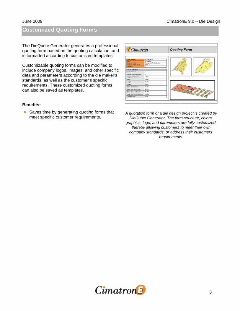
The DieQuote Generator generates a professional quoting form based on the quoting calculation, and is formatted according to customized templates.
Customizable quoting forms can be modified to include company logos, images, and other specific data and parameters according to the die maker’s standards, as well as the customer’s specific requirements. These customized quoting forms can also be saved as templates.
Benefits: Saves time by generating quoting forms that
meet specific customer requirements.
A quotation form of a die design project is created by DieQuote Generator. The form structure, colors,
graphics, logo, and parameters are fully customized, thereby allowing customers to meet their own
company standards, or address their customers’ requirements.

June 2009 CimatronE 9.0 – Die Design
4
Transfer Die Design – New Application
Transfer Die is a new application that automates and speeds up the design of transfer dies. Just like the Progressive Die application, the Transfer Die application is simple and intuitive to use, and follows the natural workflow of the die maker.
Blank and Process Design
The transfer die application can read a part from any CAD file, and then calculate its blank shape based on built-in finite element analysis tools. The part can then be formed to any intermediate station by performing a series of automated, semi-automated, and user-controlled CAD operations, including unbending, unfolding, twisting, and flanging.
The new environment consists of two distinct regions – the Process Design and Tool Design. Each region has its own set of adapted tools.
Benefits:
Saves time using dedicated design functions.
Performs blanking calculations with the industry’s fastest blank design capabilities.
Dramatically reduces the trial and error process.
The Process design guide is provided and contains a set of all tools required at each stage.
June 2009 CimatronE 9.0 – Die Design
5
Die Set and Stations Layout Design
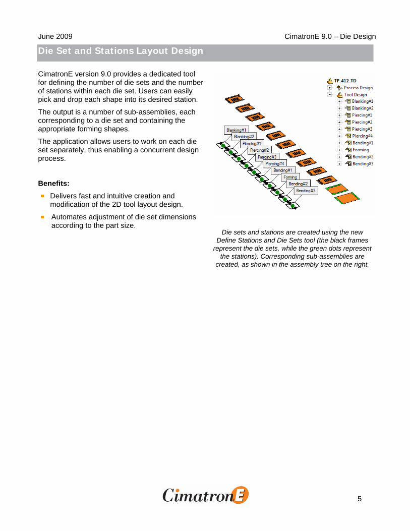
CimatronE version 9.0 provides a dedicated tool for defining the number of die sets and the number of stations within each die set. Users can easily pick and drop each shape into its desired station.
The output is a number of sub-assemblies, each corresponding to a die set and containing the appropriate forming shapes.
The application allows users to work on each die set separately, thus enabling a concurrent design process.
Benefits:
Delivers fast and intuitive creation and modification of the 2D tool layout design.
Automates adjustment of die set dimensions according to the part size.
Die sets and stations are created using the new
Define Stations and Die Sets tool (the black frames represent the die sets, while the green dots represent
the stations). Corresponding sub-assemblies are created, as shown in the assembly tree on the right.

June 2009 CimatronE 9.0 – Die Design
6
Die Tool Design
A dedicated environment includes access to pre-defined parametric die set configurations, hundreds of catalog parts, and a rich set of solid and surfacing tools to help finish any job.
The Die Tool Design application uses automated tools for rapid design of forming, trimming and piercing punches with a robust backup of hybrid solids and surfaces. The application also uses CAD functions to guarantee completion of any complex die job.
Users can now automatically design piercing punches with a single mouse click.
Benefits: Saves time by using modeling tools like the
automated parametric die set and catalog components.
Enables instant modification of the design process.
Shortens delivery time by allowing multiple users to work simultaneously on the same project.
Transfer Die Tool Design

June 2009 CimatronE 9.0 – Die Design
7
Project and Material Setup
Project Setup
Setup of the Die Tool
The new Tool tab in the Die Design Setup dialog allows users to pre-define various parameters to be used later for creating relations.
Each parameter can be assigned a value, and the dimension related to this parameter is updated accordingly.
This functionality is used to create assemblies that auto-adjust their size as soon as they are placed inside a parent assembly with a matching set of parameters.
When an assembly holding a set of parameters is placed inside an assembly holding the same set of parameters, the corresponding values are updated according to the parent assembly.
Setup formats that are suited to die design are available, as well as a general assembly format. Benefits:
Automates tool design process.
Increases standardization by re-using predefined die sets.
Shortens delivery time.
The die tool parameters are customized according to company standards and the specific project needs. In this case, the user modified the standard parameters
(shown below) and defined a new parameter file called Punch Level to be used as necessary.

June 2009 CimatronE 9.0 – Die Design
8
Material Setup
In CimatronE version 9.0, users can select the required material standard and specific material name from the Workpiece tab in the Die Setup dialog.
Material definitions are used as information to be displayed in the DieQuote Generator, and for advanced forming operations when finite element calculations are used.
Benefits: Automatically sets the appropriate material for
advanced bending operations.
In the Die Setup dialog it is now possible to specify the material commercial standard, and immediately select the required material from the dropdown list.
All available material names are listed in blue. Other names are grayed out for reference purposes only.

June 2009 CimatronE 9.0 – Die Design
9
Material Management
Material Standard and Commercial Names
In many cases, materials with the same characteristics have different commercial names. In order to ease the identification and selection of materials, it is now possible to view the existing list of materials with its commercial names (according to the local standard or supplier).
Benefits: Simplifies and eases usage of metal sheet
operations.
All functions using material data now display the selected material standard, and users can view (or
change) the specific material. For example, the Blank function dialog.

June 2009 CimatronE 9.0 – Die Design
10
View, Edit, and Define New Material Characteristics
It is a common practice to verify and tune the material parameters to make sure that the calculated bending operation predicts the real result, thus reducing the number of tryouts.
It is also possible to define a new material and add it to the list.
Benefits: Flexibility allows users to define any new
material.
In the Material Database dialog it is now possible to specify the material commercial standard, and immediately select the required material from a
dropdown list.

June 2009 CimatronE 9.0 – Die Design
11
Forming Operations
Piercing Design
Piercing Design functionality allows users to easily plan the piercing sequence of arrays of holes and to create the suitable faces.
The Piercing Design function consists of two tools – Hole Analysis and Piercing Faces. The first tool analyzes a selected forming shape, and creates contours around corresponding holes of similar shapes and size.
The contours are then used as input for the second tool that creates piercing faces in the location of selected holes, as well as capping faces for the same holes in the forming shapes that follow.
The piercing faces are later used for creating or placing catalog piercing punches.
While creating the piercing faces, the piercing forces can be viewed and analyzed.
Benefits: A piercing sequence can be easily designed
for any holes array, no matter how large.
It is very easy to modify the sequence and quickly identify what holes are left undone.
The forming shapes (shown in the upper row) are analyzed to create a group of holes marked by
boundary contours in different colors. The contours are then selected to create piercing and capping
faces (as shown in the bottom row).
June 2009 CimatronE 9.0 – Die Design
12
Skin – Overcome Sharp Corners
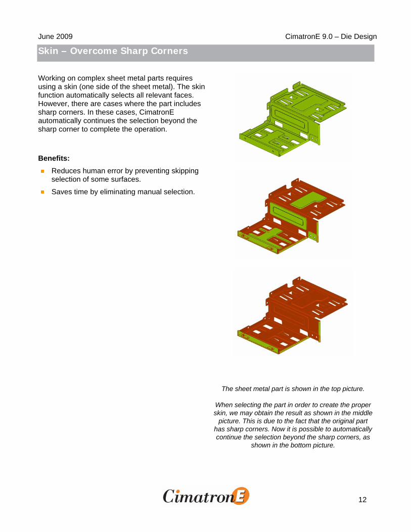
Working on complex sheet metal parts requires using a skin (one side of the sheet metal). The skin function automatically selects all relevant faces. However, there are cases where the part includes sharp corners. In these cases, CimatronE automatically continues the selection beyond the sharp corner to complete the operation.
Benefits: Reduces human error by preventing skipping
selection of some surfaces.
Saves time by eliminating manual selection.
The sheet metal part is shown in the top picture.
When selecting the part in order to create the proper skin, we may obtain the result as shown in the middle
picture. This is due to the fact that the original part has sharp corners. Now it is possible to automatically continue the selection beyond the sharp corners, as
shown in the bottom picture.

June 2009 CimatronE 9.0 – Die Design
13
Skin – New Thickness Analysis Capability
The Skin function converts a 3D solid part to a skin. In CimatronE, many die design-related functions use a skin. The skin consists of a collection of all the surfaces belonging to one side of the actual part. By using the skin as an input, CimatronE is capable of performing complex unbending functions that cannot be performed on a 3D solid part.
In version 9.0, when a face is selected in the Skin function, CimatronE compares the thickness of the 3D part at that point to the thickness value defined by the user in the Die Setup dialog. If the two values are not the same, the system displays a warning.
Benefits: Prevents user errors.
Improved automation allows the system to update the actual thickness upon user request.
In the top image, the skin surfaces (green) are distinguished from the rest of the model.
In the bottom image, the warning message is automatically issued if there is a contradiction between the thickness of the model and the
information in the setup.

June 2009 CimatronE 9.0 – Die Design
14
Unfold – Automatically Ignore Freeform Details (Dimples)
The Unfold function is used to flatten simple parts in a single operation. In the first step, the function automatically selects all relevant surfaces.
Freeform surfaces cannot be unfolded and are not selected by the unfold function. However, there are details such as dimples that consist of both simple and freeform surfaces. In CimatronE version 9.0, the Unfold function automatically ignores all the surfaces included in these details.
Benefits: Eliminates human errors by ignoring irrelevant
details.
Speeds up the die design process.
When unfolding sheet metal parts containing various shapes of dimples, as shown in the top picture,
CimatronE automatically excludes them from the selection, as shown in the bottom picture.

June 2009 CimatronE 9.0 – Die Design
15
New L-Unbend – Unbending Sharp Corners
There are many cases, such as electronic equipment dies, where the part designer does not detail some of the corners with rounds. In these cases, L-Unbend should be used. The L-Unbend function allows users to choose between the following results:
Maintain the sharp corners in the inner side of the sheet metal.
Automatically add a user-defined inner radius.
The new L-Unbend function automatically calculates a virtual bending radius according to the sheet metal thickness, the K-factor or the allowance, and the user input to generate the required result. In addition, a warning is displayed when the required results cannot be achieved.
Benefits: Saves manual operation time.
The electronic equipment component shown in the top picture is automatically flattened (bottom picture),
despite the fact its corners are designed as sharp and were not rounded.

June 2009 CimatronE 9.0 – Die Design
16
Unbend – K-Factor or Elongation
There are two standard parameters to define the material behavior during the bending process – K- factor or elongation. The K-factor defines the virtual depth where the material is neither compressed nor stretched (neutral fiber). The elongation is an empirical value that can be found in sheet metal tables.
When entering the elongation value, users can view the corresponding K-factor which is marked in red if it’s out of limits.
In CimatronE version 9.0 users can also define the elongation parameter in the unbend function.
Benefits: Increases user control by supporting empirical
elongation tables.
Eliminates human error by providing real-time validity checks.
The user unbends the red fillets using the By Elongation option.
The elongation value is -1.0. The Unbend function automatically calculates the corresponding K-factor according to the Unbend parameters, and displays
this value for reference.
In this case, the K-factor value is out of limits, and is colored in red, indicating that the elongation value is
probably incorrect.

June 2009 CimatronE 9.0 – Die Design
17
Local Blank – Region of Influence
Local Blank is used to flatten complex 3D faces connected to a planar face, using finite element (FEM) calculations.
The flattening calculation considers the geometry of 3D faces; however, the actual bending process also influences a small region of the planar face. In order to achieve more accurate results in CimatronE version 9.0, users can define the region of influence (offset of the planar face’s boundary).
Benefits: Reduces number of trials of complex parts.
Shortens overall cycle time of die design.
The local blanking as shown in the first picture takes into consideration the edge of the bend, resulting in stress distribution as shown in the second picture.
However, if we let the local blank go beyond this edge, as shown in the third picture (this scenario is
more realistic), we can see that the stress distribution is now different (bottom picture).

June 2009 CimatronE 9.0 – Die Design
18
Unbend of Simple Solid Model
While working on parts that contain only simple (cylindrical) bending, it is very useful to work on the original solid model. The new Unbend function allows easy flattening of such parts, keeping the geometry as a solid object. The advantage of this method is faster design of the punch and die set.
Benefits: Provides a quick and straightforward method of
working on simple sheet metal parts.
Shortens die design time.
In the first picture we see a sheet metal part directly from the designer. Now it is possible to use this sheet
metal as is, in order to unbend it. The user has the ability to use the Global Unbend function, and obtain
the result as shown in the middle picture. Alternatively, the user can use Local Unbend and obtain the result as shown in the bottom picture.

June 2009 CimatronE 9.0 – Die Design
19
Strip Design
Cookies – Automated Function to Design Overlap between Trimming
Punches (By Edges)
It is common practice to use several trimming punches to trim a long area. To avoid mismatches and leftovers and in order to relief the material, it is recommended to overlap between corresponding trimming punches.
The new Cookies function automates the overlap creation, and also generates the most common types of over-cutting reliefs.
Benefits: Dramatically shortens design time for trimming
punches.
Eliminates human error.
Supports changes in the strip design and blank shape.
Since the trimming punch based on the given contour has to be followed by a consecutive punch, the
contour for this punch must include some reliefs. The relief geometry can now be done with one-click using the cookie function, as shown in the bottom picture.

June 2009 CimatronE 9.0 – Die Design
20
Cookies – Automated Function to Design Relief at Contour’s Internal
Sharp Corners (By Point)
There are two cases where there is a need to relief internal corners:
Pockets for mold sliders, and inserts or pockets for die plates.
Sheet metal bending reliefs.
It is now possible to automatically detect the internal sharp corners and add the reliefs.
Benefits: Reduces design time by eliminating manual
operations.
Supports changes in strip design and blank shape.
When preparing the pocket geometry for wired or milling operations,it is often required to relief the
corners (as shown in top image). The quickest way to do this now is by using the Cookie function resulting
in a part as shown in the bottom image.

June 2009 CimatronE 9.0 – Die Design
21
Progressive Copy with Automatic Trimming
Progressive copy is used to copy dimples to the correct location on the strip. The progressive copy function automatically locates the dimple from a user-defined station along the strip and onwards.
In such an operation, it is necessary to trim the blank with the imported geometry. In CimatronE version 9.0, this operation is done automatically in all target locations, as part of the progressive copy function.
Benefits: Reduces time by eliminating the manual
trimming operation.
The part shown in the top picture contains a dimple geometry (green). When placing the unfolded parts
on the strip, the dimples can be placed automatically and their contour automatically trims the strip (bottom
picture).

June 2009 CimatronE 9.0 – Die Design
22
Single Indication – Improved Editing
When editing a contour created by a single indication option, all elements (curves and indicated surfaces) that were relevant for the creation of this contour are automatically shown. This provides the user with better visualization and editing abilities.
Benefits: Eliminates human error caused by ignoring
hidden information.
Smoothens the editing operation.
In the top image, the blue area resembles the result of a single indication operation.
When editing this operation (bottom image), the original contour and the user’s pickings are
highlighted (in red) for easy editing.

June 2009 CimatronE 9.0 – Die Design
23
Tool Design
Setup Parameters
Setup functionality has been adapted to Die Design.
When creating various relations it is now possible to relate dimensions to the Setup table that contains parameters that are fundamental to die design, or to create relations to the workpiece size itself.
Using this functionality it is possible to create various components that will automatically adjust themselves to various die parameter values used for a specific design, or to the specific workpiece size. Benefits:
Saves time with automated die design.
The length of the punch shoe has been related to the strip length using relations to the Setup table.

June 2009 CimatronE 9.0 – Die Design
24
Trimming Punch Improvements
Cut Only
The Trimming Punch function allows users to create the plate cuttings without actually creating the punch itself.
This option is required when the punch is already available and only the die plates should be cut, for example when using catalog or mirrored punches.
When using this option, multiple punch faces or contours can be selected at once. Benefits:
Saves modeling time.
Appropriate cuttings are created for both selected punch faces.
Rectangular Cut
The Trimming Punch function now allows users to create rectangular cuts for selected plates instead of shaped cuts. The rectangular cut dimensions can be directly entered, or automatically calculated according to selected punch size. Different pocket sizes may be specified for different die plates for the same punch.
Benefits: Saves modeling time.
The die backing plate and die shoe are cut with a rectangular cut, with the die shoe pocket size as
shown.

June 2009 CimatronE 9.0 – Die Design
25
Punches with Wedges
Punches can now be created with one or two fastening wedges. The wedge size, as well as the size of the pockets required to accommodate them, can be determined in an optional stage dialog. Benefits:
Saves modeling time.
The rectangular punch is created with two fastening wedges as shown.

June 2009 CimatronE 9.0 – Die Design
26
Enhanced Draft Angle Reliefs for Trimming Punches
When designing the die plate for a trimming punch unit, it is necessary to apply a draft angle to allow the cut-out material to drop down.
If the trimming contour is detailed or complex, automatic implementation of the draft angle previously did not succeed in all cases and required manual rework.
In CimatronE version 9.0, the Draft Angle Relief mechanism was improved and can now handle such cases automatically.
Benefits: Saves design time.
Supports changes in strip design and blank shape.
The images show a star-like trimming punch and its relief on the matrix side.
To allow free fall of the cutout material, the user defines a 20-degree relief angle.
Due to the detailed shape of the trimming punch, such a draft angle cannot follow the punch shape mathematically. Yet, since the draft angle is used
only as a relief, CimatronE uses a special algorithm that generates the required relief (note the roundish
shape at the bottom).

June 2009 CimatronE 9.0 – Die Design
27
Handling Changes
Easier Update of Geometrical Changes
When there is a geometry change in a die design project, users can control the implementation of the change in each of the forming shapes and stations. Previously, it was the user’s responsibility to disassociate the model at the end of the update process.
It is now possible to update the entire project or specific components. At the end of the update process, all affected components are automatically returned to Disassociate mode.
Benefits:
Automation
The top image shows an engineering change for a two-part (part and its mirror) progressive die project. The change was relevant only for the original part –
two dimples were removed and the hole at the center was enlarged (see the red arrows in the top image).
The image in the middle shows how the change was implemented in all the forming shapes using the new automated Update & Disassociate function (see the
blue arrows).
The bottom image shows part of the resulting strip. Note that the change was automatically implemented
not only on the formed shape, but also on the flattened geometry (see the blue arrows).
June 2009 CimatronE 9.0 – Die Design
28
Analysis Tools
Die Press Forces
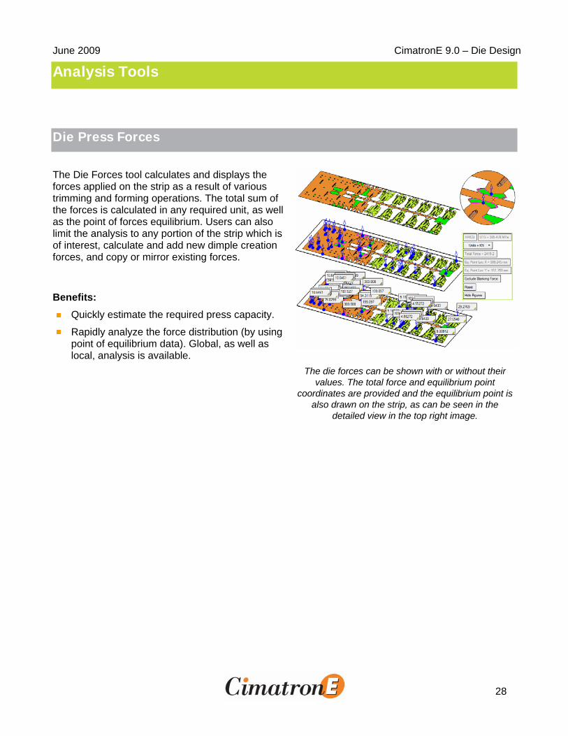
The Die Forces tool calculates and displays the forces applied on the strip as a result of various trimming and forming operations. The total sum of the forces is calculated in any required unit, as well as the point of forces equilibrium. Users can also limit the analysis to any portion of the strip which is of interest, calculate and add new dimple creation forces, and copy or mirror existing forces.
Benefits: Quickly estimate the required press capacity.
Rapidly analyze the force distribution (by using point of equilibrium data). Global, as well as local, analysis is available.
The die forces can be shown with or without their values. The total force and equilibrium point
coordinates are provided and the equilibrium point is also drawn on the strip, as can be seen in the
detailed view in the top right image.