what's new in solidworks 2012 · 2011-10-11 · insertingmagneticlinesautomatically.....55...
TRANSCRIPT

What's NewSOLIDWORKS 2012

Contents
Legal Notices....................................................................................................................ixHighlights of SolidWorks 2012........................................................................................12
1 User Interface ..............................................................................................................14Mouse Gestures and Shortcuts for Macros and Commands.................................................................14Recent Documents and Open Documents............................................................................................15
Pinning and Unpinning Recent Documents......................................................................................16Closing Documents from the Open Documents List........................................................................16Opening Containing Folders for Documents....................................................................................16
Search Commands ...............................................................................................................................17Searching for Commands.................................................................................................................17Assigning Search Shortcuts to Commands......................................................................................18Search Commands Example............................................................................................................18
Select All................................................................................................................................................19Spanning and Fitting to Displays...........................................................................................................19
Understanding Span Displays..........................................................................................................20Spanning Displays............................................................................................................................20Restoring Spanned Displays............................................................................................................21Tiling Windows in Displays...............................................................................................................21
Unit System in the Status Bar................................................................................................................23
2 SolidWorks Fundamentals...........................................................................................24Application Programming Interface........................................................................................................24Documentation.......................................................................................................................................25
New Tutorials....................................................................................................................................25Routing.............................................................................................................................................25
Document Recovery..............................................................................................................................25Blank Custom Properties.......................................................................................................................26Display...................................................................................................................................................26
Visual Improvements to the Graphics Area......................................................................................26Section Display and Coloring...........................................................................................................27Zebra Stripes and Curvature Analysis..............................................................................................28Ambient Occlusion............................................................................................................................29Ambient Occlusion Examples...........................................................................................................30
SolidWorks Resource Monitor...............................................................................................................31
3 Installation....................................................................................................................33Installation Manager...............................................................................................................................33Administrative Image Option Editor.......................................................................................................33
ii
4 Assemblies...................................................................................................................34Large Design Review ............................................................................................................................34
Assembly and Component Information............................................................................................34Reviewing Assemblies......................................................................................................................36Component Changes........................................................................................................................37Opening and Resolving Components...............................................................................................39
Usability and Workflow Improvements...................................................................................................39Creating Subassemblies..................................................................................................................39Editing Flexible Subassemblies........................................................................................................39Face and Edge Names in Lightweight Components........................................................................39Finding Missing References.............................................................................................................40Folders..............................................................................................................................................40Hiding and Showing Components....................................................................................................40Hiding the Broken Reference Indicator............................................................................................40Mate Reference Propagation...........................................................................................................40Modifying Component Dimensions...................................................................................................41Opening Assemblies.........................................................................................................................41Reloading a Component after Discarding Changes.........................................................................41Saving Components Edited Within Assemblies...............................................................................42SmartMates......................................................................................................................................42Smart Fasteners...............................................................................................................................42
5 CircuitWorks.................................................................................................................43ProStep EDMD Import and Export.........................................................................................................43
6 Configurations..............................................................................................................45Modifying Component Dimensions........................................................................................................45Equations in Configurations...................................................................................................................45
7 Costing.........................................................................................................................46SolidWorks Costing Overview ...............................................................................................................46
Setting File Locations.......................................................................................................................47Evaluating the Cost of a Sheet Metal Part.......................................................................................47Changing Costing Inputs..................................................................................................................49Switching the Costing Template.......................................................................................................50Setting a Baseline.............................................................................................................................50Changing Materials...........................................................................................................................50Modifying the Costing Template.......................................................................................................50Changing Model Geometry..............................................................................................................51Creating Reports..............................................................................................................................52
8 Drawings and Detailing................................................................................................53Align Balloons with Magnetic Lines ......................................................................................................53
Inserting Magnetic Lines...................................................................................................................54Attaching Balloons to Magnetic Lines..............................................................................................54
iii
Contents
Inserting Magnetic Lines Automatically............................................................................................55Automatically Insert Center Marks.........................................................................................................56
Inserting Center Marks Automatically...............................................................................................56Bend Tables...........................................................................................................................................57
Inserting Bend Tables.......................................................................................................................58Setting Bend Table Properties.........................................................................................................59
Highlighting Changed Dimensions.........................................................................................................59Turning On Highlighting....................................................................................................................60Specifying Highlighting Color...........................................................................................................60Changes that Are Highlighted..........................................................................................................60Isolating Changed Dimensions.........................................................................................................61
Customize Section View Label Fonts....................................................................................................62Setting Section View Label Fonts.....................................................................................................62
Display Hole Wizard Hole Sizes Using Hole Type.................................................................................63Displaying Sizes with Letters and Numbers.....................................................................................63Switching the Display.......................................................................................................................63
Exploded Drawing Views.......................................................................................................................64Improved GB Standard Templates........................................................................................................65Initiate Bill of Materials Tool Without Preselecting a View.....................................................................65Open Assemblies and Subassemblies from Drawing Views.................................................................66
Activating the Option........................................................................................................................67Opening the Component From the Context Toolbar........................................................................67Opening the Component From the Shortcut Menu..........................................................................67
Ordering Balloons .................................................................................................................................67Inserting a Bill of Materials...............................................................................................................68Inserting Balloons Following Assembly Order..................................................................................69Numbering the Balloons Sequentially..............................................................................................69Setting the First Balloon...................................................................................................................70
Punch Tables ........................................................................................................................................71Reuse Letters from Deleted Views .......................................................................................................72
Reusing Letters from Deleted Views................................................................................................72Set Section View Arrows........................................................................................................................73
Setting Arrow Types.........................................................................................................................73Stacked Balloons...................................................................................................................................73
Creating Stacked Balloons...............................................................................................................74Changing Line Lengths....................................................................................................................75Aligning Stacked Balloons................................................................................................................75Dragging Stacked Balloons..............................................................................................................75
9 eDrawings...................................................................................................................77Bills of Materials.....................................................................................................................................77File References......................................................................................................................................77
10 Equations ..................................................................................................................78Accessing the Equations Dialog Box.....................................................................................................78
iv
Contents

Three Views of Equations......................................................................................................................79Equations View.................................................................................................................................79Dimensions View..............................................................................................................................79Ordered View....................................................................................................................................80
Interface Enhancements........................................................................................................................81Sort and Filter Equations..................................................................................................................81Selecting Multiple Rows...................................................................................................................82Undo and Redo ...............................................................................................................................82Type-Ahead Entry.............................................................................................................................82Syntax Checking with Color Coding.................................................................................................82Navigate Table Cells........................................................................................................................83
Functionality Enhancements..................................................................................................................83Automatic Solve Order Option..........................................................................................................83Automatic Rebuild Option.................................................................................................................83Linking to a Text File........................................................................................................................83Suppressing Equations.....................................................................................................................84Components with Multiple Instances................................................................................................84The Measure Option.........................................................................................................................84
Create and Edit Equations in the Equations Dialog Box........................................................................85Adding an Equation..........................................................................................................................85Editing an Equation..........................................................................................................................85Suppressing an Equation.................................................................................................................86Deleting an Equation........................................................................................................................87Using the Measure Option................................................................................................................87Changing Dimensions by Configuration...........................................................................................88
Export, Import, and Link Equations to a File..........................................................................................88Linking to External Files...................................................................................................................88Exporting Equations.........................................................................................................................89Importing Equations..........................................................................................................................90Creating Equations in External Files................................................................................................90Changing Equations Through a Linked File.....................................................................................91
Create Equations in the Modify Dialog Box...........................................................................................91Creating a Global Variable...............................................................................................................91Creating an Equation........................................................................................................................92
Equations and Configurations................................................................................................................92Applying Equations to Selected Configurations...............................................................................92Unsupressing Equations to Selected Configurations.......................................................................93
Use Equations........................................................................................................................................93Exporting and Linking Equations......................................................................................................95Changing Equation Values with the Modify Dialog Box...................................................................96
11 SolidWorks Enterprise PDM.......................................................................................98Administration Tool................................................................................................................................98
Customized Enterprise PDM Menus ...............................................................................................98Displaying Full User Names in the User Interface..........................................................................100
v
Contents

Replication Failover........................................................................................................................101File Explorer and SolidWorks Add-in...................................................................................................101
Browse to Option ...........................................................................................................................101Exporting Indented Bills of Materials..............................................................................................102Searching Within File-based Dialog Boxes ...................................................................................102Version Toggle on Where Used Tab .............................................................................................103Dialog Box Toolbars.......................................................................................................................105
Product Support...................................................................................................................................106System Performance...........................................................................................................................106Web Client Access Extended..............................................................................................................106
12 Flow Simulation........................................................................................................108Physical Models and Technology........................................................................................................108
Advanced Geometry Resolution.....................................................................................................108DO Radiation Model ......................................................................................................................108Draught Rate..................................................................................................................................109Hybrid Technology for Isothermal Cavitation.................................................................................109Thermal Joint..................................................................................................................................109Tracer Study...................................................................................................................................110
Pre-Processor......................................................................................................................................110Automatic Rebuild Options.............................................................................................................110Callout at Invalid Contact................................................................................................................110Contact Resistance........................................................................................................................110
Post-Processor....................................................................................................................................111Color Bar........................................................................................................................................111Context Animation..........................................................................................................................112Crop Region for Flow Trajectories..................................................................................................112Exporting Results...........................................................................................................................112High-quality Highlight......................................................................................................................112Parameter List................................................................................................................................112Reports...........................................................................................................................................113
13 Import/Export............................................................................................................114Exporting Multisheet Drawings to the DXF or DWG Paper Space......................................................114Importing Creo Elements/Pro (Pro/Engineer) Files.............................................................................115Importing .IFC Files..............................................................................................................................115Importing Unigraphics Files.................................................................................................................115STEP and Parasolid Assembly File Import..........................................................................................116
14 Motion Studies.........................................................................................................117Motion Optimization ............................................................................................................................117Including Motion Results in Sensors....................................................................................................117
16 Parts and Features...................................................................................................119Feature Freeze ...................................................................................................................................119
Enabling Feature Freeze................................................................................................................119
vi
Contents

Freezing Features..........................................................................................................................120Exploded Views of Multibody Parts ....................................................................................................121
Creating an Exploded View............................................................................................................122Auto-spacing Bodies.......................................................................................................................124Collapsing an Exploded View.........................................................................................................125
Hole Wizard - Placement of Holes.......................................................................................................126Part Reviewer......................................................................................................................................126Templates for Split Parts......................................................................................................................127Reference Planes................................................................................................................................127
17 Routing.....................................................................................................................129Spools..................................................................................................................................................129
Defining Spools..............................................................................................................................129Splices.................................................................................................................................................130
Adding a Splice...............................................................................................................................130Custom Route Property Templates.....................................................................................................131Bills of Materials Options.....................................................................................................................132Dimensioning from Flanges.................................................................................................................132
18 Sheet Metal..............................................................................................................134Cuts Across Bends..............................................................................................................................134Edge Flanges.......................................................................................................................................134Flat Patterns.........................................................................................................................................136Forming Tools .....................................................................................................................................137
Inserting Forming Tools..................................................................................................................137Replacing Forming Tools...............................................................................................................140Linking Forming Tools....................................................................................................................141Transforming the Placement Sketch..............................................................................................141Creating Punch IDs........................................................................................................................142Inserting a Punch Table..................................................................................................................142
Swept Flanges ....................................................................................................................................143
19 Simulation................................................................................................................145Beams..................................................................................................................................................145
Beams in Linear Dynamic Studies ................................................................................................145Beam Bonding................................................................................................................................146Torsional Constants for Beams......................................................................................................147Beam Results ................................................................................................................................148
Connectors...........................................................................................................................................151Parameters Interface...........................................................................................................................152
Linking a Simulation (or Motion) Feature to a Parameter...............................................................152Motion Optimization ............................................................................................................................153Creating a Design Study with Motion Parameters...............................................................................153Optimization of a Catapult with Motion Features.................................................................................154
Defining the Design Study Variable................................................................................................155
vii
Contents

Defining Constraint and Goal.........................................................................................................155Running the Optimization...............................................................................................................155
Nonlinear Studies.................................................................................................................................156Shells...................................................................................................................................................156
Auto-bonding Shell Edges to Faces ..............................................................................................156Edge-Wing Solution for bonding Shell Edges to Solid Faces.........................................................157Import Flow Simulation Data..........................................................................................................157
20 Sketching.................................................................................................................159Dimensions..........................................................................................................................................159
Inserting Dimensions......................................................................................................................159Over Defined Sketches...................................................................................................................159Undo...............................................................................................................................................160Using Centerlines to Create Radial and Diametric Dimensions.....................................................160
Linear and Circular Sketch Patterns....................................................................................................161Downstream Features....................................................................................................................161Dimensions in Linear and Circular Patterns...................................................................................161
Shortcut Menus....................................................................................................................................161Sketch Rotation....................................................................................................................................163
21 Sustainability............................................................................................................164Increased Input Control........................................................................................................................164
Specifying Recycled Content.........................................................................................................164Specifying Manufacturing and Assembly Details...........................................................................165Specifying Part and Assembly Use Parameters.............................................................................167Specifying Shipping Details............................................................................................................168Specifying End of Life Disposal Methods.......................................................................................169Environmental Impact Dashboard Changes...................................................................................170
Adding Materials..................................................................................................................................171Updating the Materials Database...................................................................................................171Requesting Materials......................................................................................................................172
22 Toolbox ...................................................................................................................173Performance and Customization Enhancements ...............................................................................173
Customizing Toolbox......................................................................................................................173
23 Weldments...............................................................................................................177Cut List Properties...............................................................................................................................177
24 SolidWorks Workgroup PDM...................................................................................178Rebuilding Workgroup PDM Vault Metadata.......................................................................................178Accessing the Workgroup PDM Vault from Windows 7 and Windows Vista.......................................178Pack and Go Improvements................................................................................................................179
viii
Contents

Legal Notices© 1995-2011, Dassault Systèmes SolidWorks Corporation, a Dassault Systèmes S.A. company,175 Wyman Street, Waltham, Mass. 02451 USA. All Rights Reserved.
The information and the software discussed in this document are subject to change withoutnotice and are not commitments by Dassault Systèmes SolidWorks Corporation (DS SolidWorks).
No material may be reproduced or transmitted in any form or by any means, electronically ormanually, for any purpose without the express written permission of DS SolidWorks.
The software discussed in this document is furnished under a license and may be used orcopied only in accordance with the terms of the license. All warranties given by DS SolidWorksas to the software and documentation are set forth in the license agreement, and nothingstated in, or implied by, this document or its contents shall be considered or deemed amodification or amendment of any terms, including warranties, in the license agreement.
Patent Notices
SolidWorks®3D mechanical CAD software is protected by U.S. Patents 5,815,154; 6,219,049;
6,219,055; 6,611,725; 6,844,877; 6,898,560; 6,906,712; 7,079,990; 7,477,262; 7,558,705;7,571,079; 7,590,497; 7,643,027; 7,672,822; 7,688,318; 7,694,238; 7,853,940 and foreignpatents, (e.g., EP 1,116,190 and JP 3,517,643).
eDrawings®software is protected by U.S. Patent 7,184,044; U.S. Patent 7,502,027; and
Canadian Patent 2,318,706.
U.S. and foreign patents pending.
Trademarks and Product Names for SolidWorks Products and Services
SolidWorks, 3D PartStream.NET, 3D ContentCentral, eDrawings, and the eDrawings logo areregistered trademarks and FeatureManager is a jointly owned registered trademark of DSSolidWorks.
CircuitWorks, FloXpress, TolAnalyst, and XchangeWorks are trademarks of DS SolidWorks.
FeatureWorks is a registered trademark of Geometric Ltd.
SolidWorks 2012, SolidWorks Enterprise PDM, SolidWorks Workgroup PDM, SolidWorksSimulation, SolidWorks Flow Simulation, eDrawings Professional, and SolidWorks Sustainabilityare product names of DS SolidWorks.
Other brand or product names are trademarks or registered trademarks of their respectiveholders.
COMMERCIAL COMPUTER SOFTWARE - PROPRIETARY
The Software is a “commercial item” as that term is defined at 48 C.F.R. 2.101 (OCT 1995),consisting of “commercial computer software” and “commercial software documentation” assuch terms are used in 48 C.F.R. 12.212 (SEPT 1995) and is provided to the U.S. Government(a) for acquisition by or on behalf of civilian agencies, consistent with the policy set forth in48 C.F.R. 12.212; or (b) for acquisition by or on behalf of units of the department of Defense,consistent with the policies set forth in 48 C.F.R. 227.7202-1 (JUN 1995) and 227.7202-4 (JUN1995).
ix

In the event that you receive a request from any agency of the U.S. government to provideSoftware with rights beyond those set forth above, you will notify DS SolidWorks of the scopeof the request and DS SolidWorks will have five (5) business days to, in its sole discretion,accept or reject such request. Contractor/Manufacturer: Dassault Systèmes SolidWorksCorporation, 175 Wyman Street, Waltham, Massachusetts 02451 US.
Copyright Notices for SolidWorks Standard, Premium, Professional, andEducation Products
Portions of this software © 1986-2011 Siemens Product Lifecycle Management Software Inc.All rights reserved.
This work contains the following software owned by Siemens Industry Software Limited:
D-Cubed™ 2D DCM © 2011. Siemens Industry Software Limited. All Rights Reserved.
D-Cubed™ 3D DCM © 2011. Siemens Industry Software Limited. All Rights Reserved.
D-Cubed™ PGM © 2011. Siemens Industry Software Limited. All Rights Reserved.
D-Cubed™ CDM © 2011. Siemens Industry Software Limited. All Rights Reserved.
D-Cubed™ AEM © 2011. Siemens Industry Software Limited. All Rights Reserved.
Portions of this software © 1998-2011 Geometric Ltd.
Portions of this software © 1996-2011 Microsoft Corporation. All rights reserved.
Portions of this software incorporate PhysX™ by NVIDIA 2006-2010.
Portions of this software © 2001-2011 Luxology, LLC. All rights reserved, patents pending.
Portions of this software © 2007-2011 DriveWorks Ltd.
Copyright 1984-2010 Adobe Systems Inc. and its licensors. All rights reserved. Protected byU.S. Patents 5,929,866; 5,943,063; 6,289,364; 6,563,502; 6,639,593; 6,754,382; PatentsPending.
Adobe, the Adobe logo, Acrobat, the Adobe PDF logo, Distiller and Reader are registeredtrademarks or trademarks of Adobe Systems Inc. in the U.S. and other countries.
For more SolidWorks®copyright information, see Help > About SolidWorks.
Copyright Notices for SolidWorks Simulation Products
Portions of this software © 2008 Solversoft Corporation.
PCGLSS © 1992-2010 Computational Applications and System Integration, Inc. All rightsreserved.
Copyright Notices for SolidWorks Enterprise PDM Product
Outside In®Viewer Technology, © 1992-2011 Oracle
© 2011, Microsoft Corporation. All rights reserved.
Copyright Notices for eDrawings Products
Portions of this software © 2000-2011 Tech Soft 3D.
Portions of this software © 1995-1998 Jean-Loup Gailly and Mark Adler.
Portions of this software © 1998-2001 3Dconnexion.
x

Portions of this software © 1998-2011 Open Design Alliance. All rights reserved.
Portions of this software © 1995-2010 Spatial Corporation.
This software is based in part on the work of the Independent JPEG Group.
xi
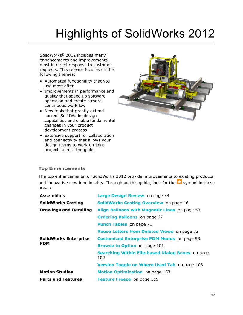
Highlights of SolidWorks 2012SolidWorks® 2012 includes manyenhancements and improvements,most in direct response to customerrequests. This release focuses on thefollowing themes:
• Automated functionality that youuse most often
• Improvements in performance andquality that speed up softwareoperation and create a morecontinuous workflow
• New tools that greatly extendcurrent SolidWorks designcapabilities and enable fundamentalchanges in your productdevelopment process
• Extensive support for collaborationand connectivity that allows yourdesign teams to work on jointprojects across the globe
Top Enhancements
The top enhancements for SolidWorks 2012 provide improvements to existing products
and innovative new functionality. Throughout this guide, look for the symbol in theseareas:
Large Design Review on page 34Assemblies
SolidWorks Costing Overview on page 46SolidWorks Costing
Align Balloons with Magnetic Lines on page 53Drawings and Detailing
Ordering Balloons on page 67
Punch Tables on page 71
Reuse Letters from Deleted Views on page 72
Customized Enterprise PDM Menus on page 98SolidWorks EnterprisePDM Browse to Option on page 101
Searching Within File-based Dialog Boxes on page102
Version Toggle on Where Used Tab on page 103
Motion Optimization on page 153Motion Studies
Feature Freeze on page 119Parts and Features
12

Exploded Views of Multibody Parts on page 121
Forming Tools on page 137Sheet Metal
Swept Flanges on page 143
Beams in Linear Dynamic Studies on page 145Simulation
Beam Results on page 148
Motion Optimization on page 153
Equations on page 78SolidWorksFundamentals
Performance and Customization Enhancements onpage 173
Toolbox
Search Commands on page 17User Interface
All features are available in SolidWorks Standard, SolidWorks Professional, and SolidWorksPremium unless otherwise noted.
For More Information
Use the following resources to learn about SolidWorks:
This guide is available in PDF and HTML formats. Click:What's New in PDFand HTML • Help > What's New > PDF
• Help > What's New > HTML
In SolidWorks, click the symbol to display the section of thismanual that describes an enhancement. The symbol appears
Interactive What'sNew
next to new menu items and the titles of new and changedPropertyManagers.
To enable Interactive What's New, click Help > What's New> Interactive.
What's New Examples are updated at every major release toprovide examples of how to use most top enhancements in therelease.
To open What's New Examples click Help > What's New >What's New Examples.
What's NewExamples
Contains complete coverage of our products, including detailsabout the user interface, samples, and examples.
Online Help
Provides information about late changes to our products.Release Notes
13

1User Interface
Enhancements to the SolidWorks user interface include a completely redesigned Equationsdialog box, a powerful Search Commands feature, quick ways to span two displays and fitdocument windows into display areas, and several other changes that simplify or speed upyour workflow.
For information on Equations, see Equations on page 78.
This chapter includes the following topics:
• Mouse Gestures and Shortcuts for Macros and Commands• Recent Documents and Open Documents• Search Commands• Select All• Spanning and Fitting to Displays• Unit System in the Status Bar
Mouse Gestures and Shortcuts for Macros and CommandsYou can assign macros and the OK, Cancel, and Escape commands to mouse gestures.You can also assign the Cancel and Escape commands to shortcut keys.
This release of the SolidWorks software does not require a \Macros folder in theSolidWorks installation directory to display and manage macros that have keyboardshortcuts. Customized macros (those assigned to keyboard shortcuts or mousegestures as well as those added to toolbars) are now managed internally. If youused a \Macros folder for macros that have shortcut keys in SolidWorks 2011 andearlier, you need to copy the folder to your SolidWorks 2012 installation directory.You can store macros that you customize in SolidWorks 2012 anywhere on yoursystem.
To assign a macro to a mouse gesture:
1. With a document open, click Tools > Customize, and select the Mouse Gestures tab.2. In Category, select Macros.
The list includes macros you have previously assigned to a shortcut key or toolbarbutton. It also includes a New Macro Button row.
To assign a mouse gesture to a macro that is not associated with a shortcut keyor toolbar button, click in the New Macro Button row, then navigate to andset up the macro in the Customize Macro Button dialog box. See SolidWorks Help:User Interface Customizations for Macros.
14

3. Assign a mouse gesture to the macro. Mouse gesture assignment works the same wayas it does for other commands. See SolidWorks Help: Reassigning Mouse Gestures.
To assign the OK, Cancel, or Escape commands to a mouse gesture:
1. With a document open, click Tools > Customize, and select the Mouse Gestures tab.2. In Category, select Others.3. Scroll to the command to which you want to assign a mouse gesture, or use the Searchfor box to find the command.
For example, type OK in Search for to find the OK command.
4. Assign a mouse gesture to the command. Mouse gesture assignment works the sameway as it does for other commands. See SolidWorks Help: Reassigning Mouse Gestures.
This illustration shows mouse gestures assigned for OK (active), Cancel (opposite OK),and a macro with a custom icon (above Cancel).
Recent Documents and Open DocumentsThe Recent Documents list can now hold up to 16 items, and you can pin favoritedocuments to the list. You can close open documents from the Open Documents list. Youcan open the folder that contains an item from either the Recent Documents or the OpenDocuments list.
Items that you highlight from the keyboard are distinct from those you highlight with themouse in the Recent Documents and Open Documents browsers.
In this illustration, the item on the left is selected with the keyboard and opens if youpress Enter. The item on the right is selected with the mouse by hovering over the item,and opens if you click the item.
15
User Interface

Pinning and Unpinning Recent DocumentsYou can pin a document to the Recent Documents list. This lets you create a set of favoritedocuments.
Do one of the following:
• Click File, hover over the item for the document, and click Pin or Unpin .• Click File > Browse Recent Documents or press R, hover over the item for thedocument, and click Pin or Unpin .
A pinned document remains at the top of the Recent Documents list until you unpinit.
Closing Documents from the Open Documents ListYou can close documents from the Open Documents list. You can close more than onedocument at a time from the Open Documents browser.
The Open Documents browser is a convenient way to close multiple documents becauseyou do not have to locate each document window individually.
Do one of the following:
• Click Window, hover over the item for an open document, and click Close .• ClickWindow > Browse Open Documents or press Ctrl + Tab, hover over theitem for each open document you want to close, and click Close . Click in thegraphics area to close the Open Documents browser.
Opening Containing Folders for DocumentsYou can open the containing folder for a document from the Recent Documents list orthe Open Documents list.
Do one of the following:
• Click File, hover over the item for the recent document, and click Show in Folder.
• Click Window, hover over the item for the open document, and click Show inFolder .
• Click File > Browse Recent Documents or press R, hover over the item for therecent document, and click Show in Folder.
• ClickWindow > Browse Open Documents or press Ctrl + Tab, hover over theitem for the open document, and click Show in Folder.
16
User Interface

Search CommandsSearch Commands lets you find and run commands from SolidWorks Search or locatea command in the user interface.
These features make it easy to find and run any SolidWorks command:
• Results are filtered as you type and typically find the command you need within a fewkeystrokes.
• When you run a command from the results list for a query, Search Commandsremembers that command and places it at the top of the results list when you type thesame query again.
• Search shortcuts let you assign simple and familiar keystroke sequences to commandsyou use regularly.
For an example of how to use Search Commands, see Search Commands Exampleon page 18.
Searching for Commands
To search for a command:
1. If Search Commands is not already active, in the SolidWorks Search list, selectCommands.
To activate Search Commands from the keyboard, press W or S. You can alsoassign another keyboard shortcut.
If you do not want the S key associated with Search Commands, click Tools >Customize. In the Customize dialog box, on the Toolbars tab, clear ActivateCommand Search when the shortcut bar is launched.
2. Start typing a search query in the SolidWorks Search box.
As you type, Search Commands displays a results list and updates it in responseto your typing. For example, when you type fit, the results list displays the commandsthat include that sequence of characters.
3. Do one or more of the following:
• To locate a command in the SolidWorks user interface, hover over the commandin the results list and click Show Me .
• To run a command, click the command, or highlight the command and press Enter.
If a command cannot run, it is unavailable in the results list and appears lowerin the list. For example, many commands cannot run unless a document isopen.
• To add a command to a toolbar, drag the command from the results list and dropit on the toolbar.
17
User Interface

Assigning Search Shortcuts to Commands
To assign a search shortcut to a command:
1. Click Tools > Customize, and select the Keyboard tab.2. Navigate to the command to which you want to assign a search shortcut.
See SolidWorks Help: Customize Keyboard.
3. In the Search Shortcut column for the command, type the shortcut you want touse, then click OK.
Search Commands ExampleThis example shows how you might use Search Commands to find and run the CurveThrough Reference Points command.
For full instructions on using Search Commands, see Search Commands on page 17.
With a part or assembly open, start typing curve through reference points in SearchCommands. As soon as you type cur, the results list displays only those commands thatinclude the character sequence "cur," and Curve Through Reference Points appearsnear the top of the results list.
If you click Show Me for Curve Through Reference Points, a red arrow indicatesthe command in the user interface.
If it is not already visible, the toolbar or menu containing the command opens.
If you run Curve Through Reference Points from the results list, the command appearsat the top of the list the next time you search using cur.
If you assign Curve Through Reference Points the search shortcut crp, the commandis the only one found in the results list when you search by typing crp.
Because you can activate Search Commands using the W or S key, and the first item inthe results list is automatically highlighted, you can run Curve Through ReferencePoints without leaving the keyboard. Press W or S, then type crp, then press Enter.
18
User Interface

Select AllSelect All selects everything in the graphics area, as if you made a box selection coveringthe entire area.
For parts, Select All respects any active selection filters when it makes the selection.For assemblies, Select All, like box selection, selects all components.
To select everything in the graphics area:
• Click Edit > Select All, or press Ctrl+A.
To limit the selection to specific entities in a part, pre-select one or more entities inthe graphics area. For example, pre-select an edge and a vertex to limit the selectionto all edges and vertices.
This table provides examples of Select All performed in different circumstances on apart.
After Select AllBeforeDescription
No filters active, and nopre-selection
No filters active, and avertex pre-selected
Filter Faces active, andno pre-selection
Spanning and Fitting to DisplaysYou can automatically position and size the main SolidWorks window to span two displays.You can also position and size two document windows conveniently across one or twodisplays.
19
User Interface

Understanding Span DisplaysIf you have multiple displays, you can use Span Displays to span two displays withoutmanually resizing the SolidWorks window.
If you have two displays configured side-by-side, Span Displays spans the two displaysusing the height of the display with the smallest vertical resolution, as shown.
If you have two displays configured one above the other, Span Displays spans the twodisplays using the width of the display with the smallest horizontal resolution, as shown.
If you have more than two displays, Span Displays spans only two of them, and usesthe following priority order to determine which additional display to span: right, left,bottom, top. For example, if a display is available to the right of the current display, SpanDisplays spans that display. If displays are available above and below the current display,Span Displays spans the display below.
When the SolidWorks window partially or fully spans two monitors:
• A document that you drag from Windows Explorer opens on the monitor where youdrop it.
• Open documents stay on their current monitor when you use Windows > Tile orWindows > Cascade to organize them.
You can also Alt + click one of the Tile buttons in a document window to span twodisplays and tile the document window at the same time.
Spanning Displays
To span two displays:
Click Span Displays or Window > Span Displays.
The Span Displays button is on the right side of the SolidWorks window's title bar.
20
User Interface

The icon changes to if the only available displays are configured one above theother.
Restoring Spanned Displays
To restore the SolidWorks window to its previous size and position when it spans twodisplays:
Click Restore or Window > Restore.
The Restore button is on the right side of the SolidWorks window's title bar.
Tiling Windows in DisplaysYou can tile a document window so it occupies half of one display, or all available spaceon one of two displays. You can also resize the SolidWorks window to fill a single displayor to span two displays at the same time as you tile a document window.
This functionality is useful for arranging two document windows to take advantage of theavailable display area. For example, you can tile a document window containing anassembly on one display and a document window containing a part from that assemblyon the other. This is also a good way to arrange two document windows when you havemore than two document windows open. (Windows > Tile, in contrast, arranges all theopen documents.)
To tile a document window in the display:
Click or Alt + click Tile Left , Tile Right , Tile Top , or Tile Bottomin the document window's title bar.
If two displays are configured side-by-side, or if only one display is connected,the available buttons are Tile Left and Tile Right. If two displays are configuredone above the other, the available buttons are Tile Top and Tile Bottom.
When you click a Tile button, the document window is resized and repositioned butthe SolidWorks window is not changed.
When you Alt + click a Tile button, the document window and the SolidWorks windoware resized and repositioned. If multiple displays are connected, the SolidWorkswindow spans two displays. If only one display is connected, the SolidWorks windowis maximized.
The following table describes the results for different display configurations andillustrates the results when you click or Alt+click Tile Left and Tile Right to tile twodocuments.
21
User Interface

ResultWhen Alt+clickingResult When ClickingDisplay Configuration
The document windows tileto the appropriate display.
The document windows tileto the appropriate display.
Two or more displaysavailable. The SolidWorkswindow fully spans twodisplays.
The SolidWorks windowresizes to span two displaysand the document windowstile to the appropriatedisplay.
The document windows tileto the appropriate display.
Two or more displaysavailable. The SolidWorkswindow spans one displayplus a substantial part of asecond display.
The SolidWorks windowresizes to span two displaysand the document windowstile to the appropriatedisplay.
The document windows tileto occupy 50% of theavailable display area. (Thewindow on the right doesnot attempt to tile to thesmall area occupied by theSolidWorks window on thesecond display.)
Two or more displaysavailable. The SolidWorkswindow spans one displayplus a small part of asecond display.
The SolidWorks windowresizes to span two displaysand the document windowstile to the appropriatedisplay.
The document windows tileto the appropriate half ofthe display.
Two or more displaysavailable. The SolidWorkswindow occupies all or partof one display only.
22
User Interface

The document windows tileto the appropriate half ofthe display.
The document windows tileto the appropriate half ofthe display.
One display available. TheSolidWorks window ismaximized on the display.
The SolidWorks windowmaximizes to fill the displayand the document windowstile to the appropriate halfof the display.
The document windows tileto the appropriate half ofthe display.
One display available. TheSolidWorks window is notmaximized on the display.
Unit System in the Status BarUnit System shows the unit system for the active document in the status bar and letsyou change or customize the unit system.
Unit System is located next to Quick Tips in the status bar.
For example, MMGS is displayed when the unit system for the active document ismillimeters, grams, seconds.
To view the full unit system name in a tooltip, hover over Unit System with the pointer.
To select a different unit system or to customize the unit system, click Unit System,then select a unit system, or click Edit Document Units to open the Document Properties- Units dialog box.
23
User Interface
2SolidWorks Fundamentals
New features include display improvements, better low-resource warnings, and better autosaveand document recovery processes.
This chapter includes the following topics:
• Application Programming Interface• Documentation• Document Recovery• Blank Custom Properties• Display• SolidWorks Resource Monitor
Application Programming InterfaceEnhancements in the SolidWorks 2012 Application Programming Interface (API) are theability to:
• Determine whether any buttons of a CommandGroup are enabled.• Get and set the faces to exclude from Flat-Pattern features.• Add objects to selection lists without preselecting them through the user interface.• Sort bill of materials, hole, weldment cut list, and general tables.• Specify equal spacing between pattern instances in circular pattern features.• Insert DXF/DWG image features into a part or drawing.• Select chains of entities attached to sketch segments.• Close drawings without unloading their references from memory and reopen them.• Isolate changed dimensions.• Specify configuration names when setting the files to open in response to SolidWorksevents.
• Specify a rebuild option when activating documents.• Get system information.• Suppress multiple notifications while dragging or spinning the slider of number boxeson PropertyManager pages.
• Anchor notes.• Automatically insert center marks.• Specify the math transform to use in interference detection.• Get and set display modes, visual properties, transparency states, and visibility statesof specified components in specified display states for a specified scope.
• Specify balloon options when creating balloon, auto balloon, and stacked balloonannotations.
• Get the number of virtual sharp witness lines and their geometry data.• Insert magnetic lines in drawing sheets.
24

• Insert bend table annotations in drawing views.• Modify, insert, and delete the features, components, and reference entities of SmartComponents.
• Specify whether to color section view caps.• Get the fixed face of Flatten-Bends features.
See SolidWorks 2012 API Help Release Notes for late-breaking updates.
Documentation
New TutorialsSolidWorks 2012 includes a new PhotoView 360 and Appearances tutorial and an enhancedAnimation tutorial.
To access these tutorials:
1. Click Help > SolidWorks Tutorials.2. Click one of the following:
• All SolidWorks Tutorials (Set 1) (Animation Tutorial)• All SolidWorks Tutorials (Set 2) (PhotoView 360 and Appearances)
3. Select the tutorial from the list.
Routing
Changes to routing documentation include a new Getting Started section. This sectiondescribes best practices for setting up and managing your routing projects.
Document RecoveryAuto-recover is simpler and more reliable. Document recovery information in theSolidWorks Recovery tab of the Task Pane is easier to understand and respond to.
You can determine how often auto-recover information is saved by setting an interval inminutes.
In SolidWorks 2011 and earlier, you can control how often auto-recover informationis saved based on the number of changes you make to a document. This option isnot available in SolidWorks 2012.
You can also determine where auto-recover information is saved on your system.
The Auto-recover folder must be a folder on your local system and cannot be anetwork location.
See SolidWorks Help: Backup/Recover Options.
25
SolidWorks Fundamentals
When you start SolidWorks after the system has terminated unexpectedly, any availableauto-recovered documents are listed under Document Recovery in the SolidWorksRecovery tab of the Task Pane.
To open an auto-recovered document, double-click the document in the DocumentRecovery list, or right-click the document and click Open.
You can then choose to save the document either by using Save to replace the originalfile or by using Save As to create a new file.
To delete an auto-recovered document, right-click the document and click Delete.
Blank Custom PropertiesYou can create blank custom or configuration-specific properties in the SummaryInformation dialog box.
This functionality is useful, for example, when you want to create a template that containscustom properties but you do not want to give those properties specific starting values.
To add a blank custom or configuration-specific property:
1. Click File > Properties.2. On the Custom tab or the Configuration Specific tab:
a. Click <Type a new property> in the Property Name column for the blank propertyrow, then type a custom property name.
b. Select a property type in the Type column for the new property.
3. If necessary, repeat step 2 to add more custom properties.4. Click OK.
DisplayEnhancements to display capabilities include improvements to the look of the graphicsarea, changes to section display and coloring, better images for curvature analysis, andthe wider availability of ambient occlusion.
Visual Improvements to the Graphics AreaThe graphics area, and sketch mode in particular, has an improved appearance.
Lines, arrows, text, and numbers are anti-aliased. Items such as dimension leader lines,balloons, origins, points, and spline controls have an improved look.
26
SolidWorks Fundamentals

SolidWorks 2012SolidWorks 2011
Additionally, the list of scenes available from Apply scene (Heads-up View toolbar)is organized into categories that match the structure of the Scenes folder.
Section Display and ColoringSection views are available in a part or assembly when the Section View PropertyManageris not open, and persist when you save and re-open the document. You can display apart or assembly with or without section caps. If you display section caps, you can turnthe cap color on or off.
To control how section views display:
1. Click Section View (View toolbar) or View > Display > Section View.2. In the PropertyManager, select options to define your section views. See SolidWorks
Help: Section View PropertyManager (Models).3. Select or clear Show section cap.4. If you selected Show section cap, select or clear Keep cap color.
5. Click .
The section view remains visible for the part or assembly. The following illustrationsshow the possible section view displays for an assembly.
27
SolidWorks Fundamentals
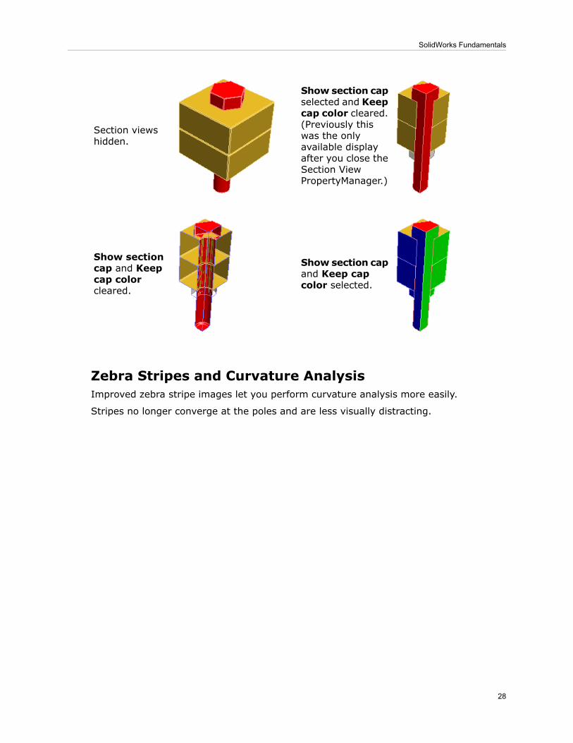
Show section capselected and Keepcap color cleared.(Previously thiswas the onlyavailable displayafter you close theSection ViewPropertyManager.)
Section viewshidden.
Show section capand Keep capcolor selected.
Show sectioncap and Keepcap colorcleared.
Zebra Stripes and Curvature AnalysisImproved zebra stripe images let you perform curvature analysis more easily.
Stripes no longer converge at the poles and are less visually distracting.
28
SolidWorks Fundamentals
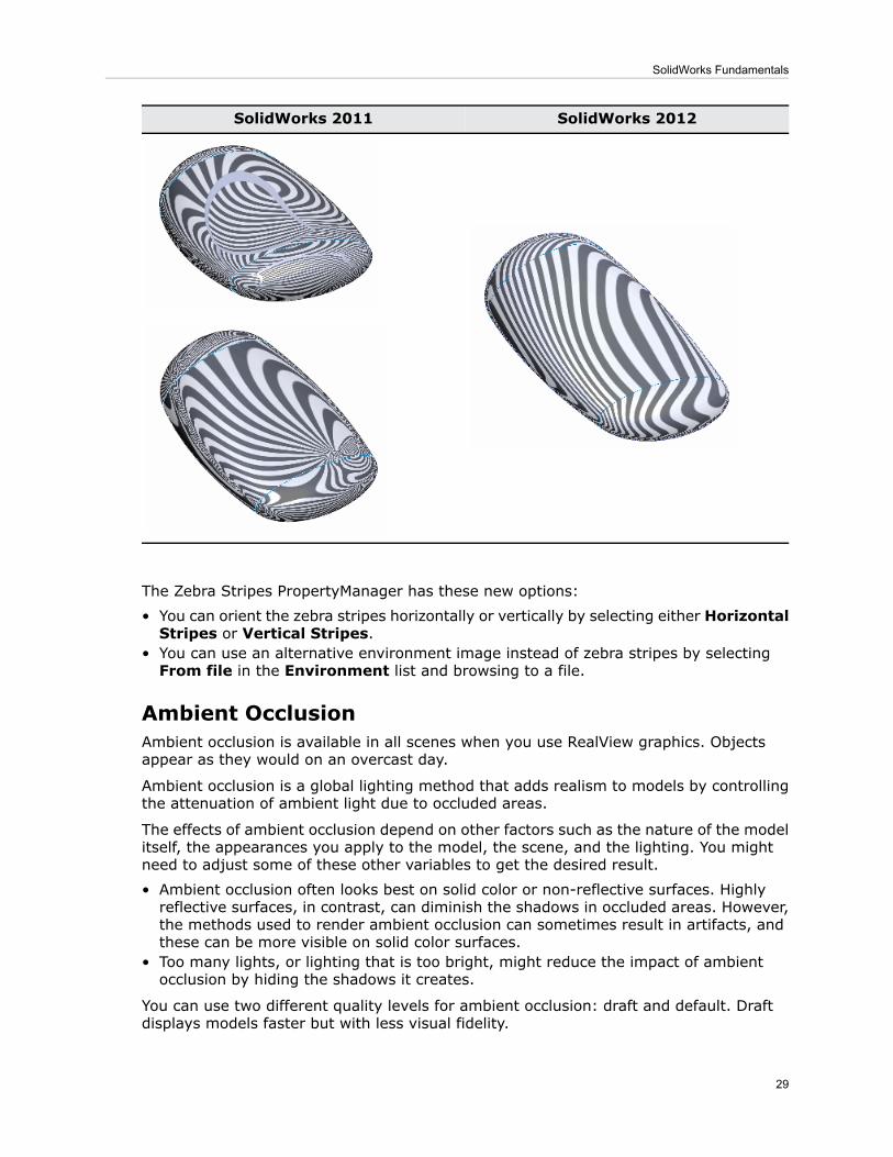
SolidWorks 2012SolidWorks 2011
The Zebra Stripes PropertyManager has these new options:
• You can orient the zebra stripes horizontally or vertically by selecting either HorizontalStripes or Vertical Stripes.
• You can use an alternative environment image instead of zebra stripes by selectingFrom file in the Environment list and browsing to a file.
Ambient OcclusionAmbient occlusion is available in all scenes when you use RealView graphics. Objectsappear as they would on an overcast day.
Ambient occlusion is a global lighting method that adds realism to models by controllingthe attenuation of ambient light due to occluded areas.
The effects of ambient occlusion depend on other factors such as the nature of the modelitself, the appearances you apply to the model, the scene, and the lighting. You mightneed to adjust some of these other variables to get the desired result.
• Ambient occlusion often looks best on solid color or non-reflective surfaces. Highlyreflective surfaces, in contrast, can diminish the shadows in occluded areas. However,the methods used to render ambient occlusion can sometimes result in artifacts, andthese can be more visible on solid color surfaces.
• Too many lights, or lighting that is too bright, might reduce the impact of ambientocclusion by hiding the shadows it creates.
You can use two different quality levels for ambient occlusion: draft and default. Draftdisplays models faster but with less visual fidelity.
29
SolidWorks Fundamentals

To use ambient occlusion:
1. Click View Settings (Heads-up View toolbar) or View > Display, then clickRealView Graphics.
2. Click View Settings (Heads-up View toolbar) or View > Display, then clickAmbient Occlusion.
RealView Graphics is only available with graphics cards that support RealViewGraphics display.
To change the display quality level for Ambient Occlusion, click Tools > Options.On the System Options tab, click Display/Selection, then select or clear Displaydraft quality ambient occlusion.
Ambient Occlusion Examples
Model with appearancesModel with solid color surfaces
Ambient Occlusion off
Ambient Occlusion on and using default quality
30
SolidWorks Fundamentals

Ambient Occlusion on and using draft quality
SolidWorks Resource MonitorThe SolidWorks Resource Monitor utility monitors resources that your SolidWorks softwareor your system is using. When you are running low on resources, the SolidWorks ResourceMonitor provides messages in the notification area of the Windows taskbar that help youtake action to avoid a system failure or a loss of data.
The SolidWorks Resource Monitor monitors these resources:
DescriptionResource
The combined total of physical RAM and page file size. In Windows, thiscombined total is known as the Commit Charge.
Systemmemory
A finite resource used to draw user interface items on the screen.GDI handles
The maximum amount of memory available to the SolidWorks software(2GB).
Processmemory(SolidWorks32-bit only)
There is no equivalent for SolidWorks 64-bit as the memory availableto a process is only limited by the system memory.
The SolidWorks Resource Monitor's icon in the notification area is color-coded to indicatethe availability of resources:
DescriptionColor
Sufficient resources of all types are available.Green
One or more resources are running low. You should take action to freeresources.
Yellow
One or more resources are almost completely consumed. If you continue towork you are likely to experience a system failure or loss of data, so youmust take action to free resources. In addition to the messages provided bythe monitor in the notification area, messages appear in the SolidWorkssoftware if you attempt to execute any commands.
Red
31
SolidWorks Fundamentals

The SolidWorks Resource Monitor displays messages that are specific to the type ofresource that has run low. Follow the directions in the message to correct the resourceproblem.
For example, if system memory is low, close non-SolidWorks programs or close documentswithin SolidWorks. If the number of available GDI handles is low, close documents withinSolidWorks.
To display the most recent message again, click the SolidWorks Resource Monitor
icon - , , or - in the notification area.
The SolidWorks Resource Monitor has no user interface other than the icon andmessages. Nothing appears on the screen if you double-click the icon, or click itbefore a message has appeared.
32
SolidWorks Fundamentals

3Installation
This chapter includes the following topics:
• Installation Manager• Administrative Image Option Editor
Installation ManagerSolidWorks Installation Manager is enhanced.
• You can completely uninstall the SolidWorks software or customize the software removalby removing one or more of the following items: Program Files and Folders, registryentries, data folders such as SolidWorks Toolbox, and previously downloaded installationfiles and folders. By default, the SolidWorks Installation Manager removes ProgramFiles and Folders.
1. To uninstall SolidWorks in Windows Vista and later, click Start > Control Panel >Programs > Programs Features. For Windows XP, click Start > Control Panel> Add or Remove Programs.
2. From the Summary screen in the SolidWorks Installation Manager, click Change.Select items to remove from the Advanced Options screen.
• You can specify which standards to support before installing the SolidWorks Toolbox.By default, all standards are selected for a new installation of the Toolbox. To selectstandards:
1. In the Summary screen, expand Products and click Change.2. In the Product Selection screen, expand SolidWorks > SolidWorks Toolbox andselect standards from a list.
• The installation of the Workgroup PDM Server requires a validation code. The InstallationManager can obtain the code automatically. If an Internet connection is not available,you can obtain the code by email.
Administrative Image Option EditorSolidWorks Administrative Image Option Editor is enhanced.
• Administrators can use new uninstall options to perform a complete or custom uninstallon client computers. The uninstall options are available in the Client Installation Optionssection of the Option Editor. To view the options, click Yes, perform a customuninstall and then select items for removal.
• Administrators can also preselect SolidWorks Toolbox standards from a list.
33

4Assemblies
This chapter includes the following topics:
• Large Design Review• Usability and Workflow Improvements
Large Design ReviewLarge Design Review lets you open very large assemblies quickly, while still retainingcapabilities that are useful when conducting design reviews of assemblies.
When you open an assembly in Large Design Review mode, you can:
• Navigate the FeatureManager design tree• Measure distances• Create cross sections• Hide and show components• Create, edit, and play back walk-throughs
To open an assembly in Large Design Review mode, click Open (Standard toolbar)or File > Open. In the dialog box, select the assembly you want to open, and then, inMode, select Large Design Review.
Assembly and Component InformationInformation about the assembly and its components is limited in Large Design Review.
FeatureManager Design TreeThe FeatureManager design tree displays information about the assembly componentsand hierarchy.
Information displayed in the tree includes:
• Component names• Assembly and subassembly hierarchy
An eye overlay appears on the icons of all components when the assembly is opened inLarge Design Review mode.
34

Information about the following items is not shown in theFeatureManager design tree:
Limitation
• Assembly features• Component patterns• Mates
Assembly StatisticsIn AssemblyXpert, you can see assembly statistics such as number and type ofcomponents, depth of the assembly hierarchy, etc.
Click AssemblyXpert (Large Design Review tab of the CommandManager) or Tools> AssemblyXpert.
The reported assembly statistics are approximate. They can differ fromthe numbers reported when the document is opened in resolved orlightweight mode.
Limitation
AssemblyXpert diagnostic tests are not available in Large Design Review.
Component PropertiesYou can view component properties, but you cannot change them.
Right-click a component and click Component Properties .
You can see information such as:
• Model Document Path• List of configurations
You cannot change the properties. For example, you cannot:Limitation
• Switch configurations• Switch between flexible and rigid
35
Assemblies

Reviewing AssembliesMost of the capabilities in Large Design Review mode are limited versions of existingSolidWorks capabilities. Snapshots are a new capability available only in Large DesignReview.
Most available tools appear on the Large Design Review tab of the CommandManager.
MeasurementsYou can measure the distance between entities in Large Design Review.
Click Measure or Tools > Measure. When you select two entities (vertices, edges,or faces) the software reports the approximate distance between them.
Measurements reported in Large Design Review are approximate.To obtain accurate measurements, you must resolve the components.
Limitation
Section ViewsYou can create section views in Large Design Review.
Click Section View or View > Display > Section View. You can select one or moreof the three standard planes to section the model. You can cap the ends of the sectionview.
You cannot select other planes to section the model.Limitation
IsolateYou can use Isolate to focus on selected components.
Select one or more components, and then right-click and click Isolate.
Walk-throughsYou can create Walk-throughs in Large Design Review just as you do in resolved mode.
Click Add Walk-through or View > Lights and Cameras > Add Walk-through.Walk-throughs can be played back in both Large Design Review and resolved modes,regardless of which mode they were created in.
SnapshotsSnapshots are a new capability available only in Large Design Review. You can takesnapshots of locations that you want to return to.
A snapshot captures the state of the graphics area, similar to a custom named view, and
saves it in a Snap feature on the DisplayManager tab of the Manager Pane. Unlike acustom named view, if some parts are hidden when you take a snapshot, those parts arealways hidden when you return to that snapshot.
Click Take Snapshot or View > Lights and Cameras > Take Snapshot, or pressAlt + Spacebar.
You can:
36
Assemblies
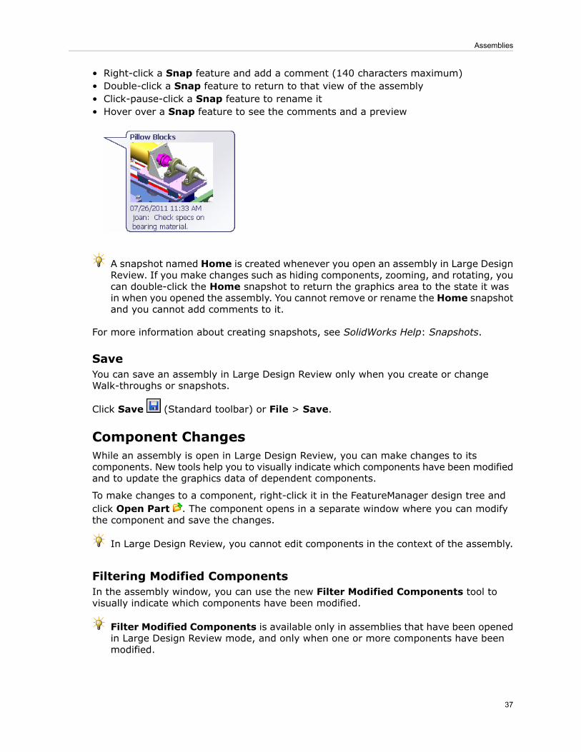
• Right-click a Snap feature and add a comment (140 characters maximum)• Double-click a Snap feature to return to that view of the assembly• Click-pause-click a Snap feature to rename it• Hover over a Snap feature to see the comments and a preview
A snapshot named Home is created whenever you open an assembly in Large DesignReview. If you make changes such as hiding components, zooming, and rotating, youcan double-click the Home snapshot to return the graphics area to the state it wasin when you opened the assembly. You cannot remove or rename the Home snapshotand you cannot add comments to it.
For more information about creating snapshots, see SolidWorks Help: Snapshots.
SaveYou can save an assembly in Large Design Review only when you create or changeWalk-throughs or snapshots.
Click Save (Standard toolbar) or File > Save.
Component ChangesWhile an assembly is open in Large Design Review, you can make changes to itscomponents. New tools help you to visually indicate which components have been modifiedand to update the graphics data of dependent components.
To make changes to a component, right-click it in the FeatureManager design tree andclick Open Part . The component opens in a separate window where you can modifythe component and save the changes.
In Large Design Review, you cannot edit components in the context of the assembly.
Filtering Modified ComponentsIn the assembly window, you can use the new Filter Modified Components tool tovisually indicate which components have been modified.
Filter Modified Components is available only in assemblies that have been openedin Large Design Review mode, and only when one or more components have beenmodified.
37
Assemblies

When Filter Modified Components is enabled and you edit and save a component ina separate window, the changed component remains opaque in the assembly window,while unchanged components become transparent. Using Filter Modified Componentsallows you to see more easily which components have been modified.
Modified components include:
• Components that are detected as out of date when you open the assembly in LargeDesign Review
• Components that you modify and save in a separate window during the current LargeDesign Review session
To filter modified components:
1. Click Filter Modified Components or View > Modify > Filter ModifiedComponents.
2. In the PropertyManager:a) Select Enable.Modified components remain opaque; unmodified components become transparent.
b) Use the slider to adjust the transparency.
Select Dynamic to see the transparency level change in the graphics area asyou move the slider in the PropertyManager.
3. Click .
To turn off the transparency, click Filter Modified Components again and clearEnable.
LDR UpdateYou can use LDR Update to update the graphics data of a dependent component thatbecomes out of date due to changes to its parent component.
If changes that you make to one component influence a dependent component, then thegraphics data in Large Design Review might become out of date for the dependentcomponent.
Examples of changes that might require LDR Update:
38
Assemblies

• A change to an equation in one part that influences a dimension in another part.• A change to a part that is the seed component for a mirrored part.
To update the graphics data:
1. Right-click the assembly name at the top of the FeatureManager design tree.2. Click LDR Update.
Opening and Resolving ComponentsSelective Open is available on the Large Design Review tab of the CommandManager.Previously it was in the Open dialog box. New tools let you selectively open as lightweight,or set all components to resolved or to lightweight.
The following commands cause the software to exit Large Design Review. You mightnotice a delay while component data is loaded. To return to Large Design Review,close and reopen the assembly.
• Selective Open . In the Selective Open dialog box, select components to fully load.Other components are not loaded and become hidden.
• Selective Open in Lightweight (on Selective Open flyout tool). In the SelectiveOpen in Lightweight dialog box, select components to load as lightweight. Othercomponents are not loaded and become hidden.
• Set All to Resolved . All components are fully loaded.
• Set All to Lightweight (on Set All to Resolved flyout tool). All components areloaded as lightweight.
Usability and Workflow ImprovementsVarious assembly areas have been enhanced to add shortcuts, remove limitations, andstreamline workflows and dialogs.
Creating SubassembliesYou can preselect components in the parent assembly's graphics area when creating asubassembly. Previously, you could preselect only components in the parent assembly'sFeatureManager design tree.
In an assembly, in the graphics area, select several components. Then right-click andclick Form New Subassembly.
Editing Flexible SubassembliesYou can edit flexible subassemblies in the context of their parent assemblies.
Face and Edge Names in Lightweight ComponentsWhen replacing components in assemblies, if you select Re-attach mates, the softwarecan access previously assigned face and edge names in lightweight components.
39
Assemblies

If you have previously assigned names to mated entities (faces or edges), then whenyou replace one component with another, you can reattach the mates automaticallywithout resolving the original component.
Previously, the mates would not reattach automatically because the software could notaccess the entity names in lightweight mode.
You must save the assembly in SolidWorks 2012 to access the face and edge namesin lightweight components.
Finding Missing ReferencesWhile opening an assembly that has multiple missing references, the process of findingthose references is simplified.
The software tracks each folder where you find a missing reference and checks thosefolders for subsequent missing references.
Previously, the software tracked only the most recent folder. If the missing referenceswere in several folders, you often had to browse to the same folder multiple times.
FoldersWhen adding a folder in the FeatureManager design tree, you can preselect non-sequentialcomponents or mates to place in the folder.
In an assembly, in the FeatureManager design tree, select several non-sequentialcomponents or several non-sequential mates. Right-click and click Add to New Folder.
Hiding and Showing ComponentsIn the graphics area, you can press Tab and Shift + Tab to hide and show components.
To hide a component, move the pointer over it and press Tab. To show a component,move the pointer over an area containing a hidden component and press Shift + Tab.
You can use these commands regardless of the component's state (resolved, lightweight,SpeedPak, or Quick view). The commands are not available when another command isactive.
Hiding the Broken Reference IndicatorA system option lets you hide the x that appears in the FeatureManager design tree toindicate broken references.
Click Tools > Options > System Options > External References and clear Show"x" in feature tree for broken external references.
Mate Reference PropagationWhen you insert a subassembly into a higher-level assembly, mate references defined inthe subassembly’s components are available for automatic mating.
Previously, only mate references defined in the subassembly’s top level were available.
40
Assemblies
Modifying Component DimensionsYou can edit the dimensions of a multiple-configuration component in the assembly ordrawing environment, regardless of which configuration is active in the componentdocument.
Previously, in an assembly or drawing, you could not edit the configured componentdimensions unless the configuration you were editing was also the active (open or lastsaved) configuration in the component document.
In an assembly with a component that has multiple configurations, double-click a dimensionthat has a different value for each configuration. In the Modify dialog box, you can set anew value for the dimension and specify to which configurations the change applies.
Opening AssembliesIn the Open dialog box, checkboxes for various assembly modes have been replaced bytheMode drop-down list. Quick view / Selective open has been moved to Large DesignReview.
Click Open (Standard toolbar) or File > Open. In the dialog box, select the assemblyyou want to open. The Mode drop-down list appears. Available modes include:
• Resolved• Lightweight• Large Assembly Mode• Large Design Review
The Use Speedpak checkbox is shown only for modes that allow it.
Quick view / Selective open is no longer available in the Open dialog box for assemblies.Instead, in Mode, select Large Design Review. On the CommandManager, click
Selective Open . See Opening and Resolving Components on page 39.
Reloading a Component after Discarding ChangesYou no longer need to manually reload a component in the assembly file when you discardchanges made in the component file. When you close the component file without savingit, a dialog box asks if you want to keep or discard the changes in the assembly.
1. Open an assembly, then open one of its components in a separate window.2. Make changes to the component.3. Click File > Close.
A dialog box asks if you want to save the changes.
4. Click No.
A dialog box explains that because the component is open in another window, changesyou made to the component will still appear in that other window.
5. Click one of the following:
41
Assemblies
Keeps the changes in the assembly file, even though you did notsave them in the component file. For example, click Yes whenyou want to make more changes to the component, but you needto make them in the context of the assembly.
Yes
When you save the assembly file, changes to the componentare saved to the component file.
Reloads the unchanged component file into the assembly file, sothat the changes no longer appear in the assembly.
No
Keeps the component file open so you can make other changesor save the file.
Cancel
Saving Components Edited Within AssembliesThe Resolve Ambiguity dialog box has been eliminated.
When you save a component that you are editing in the assembly window, the componentis saved. You are no longer asked whether you want to save the component file or theassembly file.
SmartMatesTo invoke SmartMates between two components already in an assembly, you can pressand hold Alt after selecting a face to drag. Previously, you had to press and hold Altbefore selecting the face.
Smart FastenersWhen inserting Smart Fasteners, the software recognizes more holes that were not createdwith the Hole Wizard or Hole Series tools, such as holes created by various mirroring andpatterning operations.
42
Assemblies

5CircuitWorks
Available in SolidWorks Premium.
This chapter includes the following topics:
• ProStep EDMD Import and Export
ProStep EDMD Import and ExportProStep EDMD (*.idx) files are supported by major ECAD vendors. Use this file formatto collaborate with your ECAD designers on an ECAD design. You can export CircuitWorks™data to ProStep EDMD files and you can import ProStep EDMD files into CircuitWorks.CircuitWorks communicates proposed changes to the ECAD files to the ECAD designerand updated changes to ProStep EDMD files are communicated back to CircuitWorks whenyou import the ECAD data.
To open a ProStep EDMD file, click CircuitWorks > Open ECAD File, navigate to theProStep EDMD file and click Open. To set the ProStep EDMD options, in the CircuitWorks
Options dialog box, click the ProStep EDMD tab.
43

See SolidWorks Help: ProStep EDMD Files.
44
CircuitWorks
6Configurations
This chapter includes the following topics:
• Modifying Component Dimensions• Equations in Configurations
Modifying Component DimensionsYou can edit the dimensions of a multiple-configuration component in the assembly ordrawing environment, regardless of which configuration is active in the componentdocument.
See Modifying Component Dimensions on page 41.
Equations in ConfigurationsYou can configure equations more easily. The new behavior for configuring equations issimilar to the existing behavior for dimensions.
See Equations on page 78.
45
7Costing
This chapter includes the following topics:
• SolidWorks Costing Overview
SolidWorks Costing OverviewThe SolidWorks Costing tool helps you calculate how much it costs to manufacture sheetmetal and machined parts by automating the cost estimation and quotation process.
The tool helps designers make design decisions based on the cost to manufacture, andhelps manufacturers create quotes for customers. Whenever you change a design, youcan see the new, updated cost immediately, along with a detailed cost breakdown.Additionally, you can generate automatic cost reports.
The Costing tool is driven by manufacturing and material information in templates thatdetermine the manufacturing cost. In the templates you can specify the material usedto create the part, the manufacturing processes (such as laser cutting, bending, or milling),and the associated costs of these materials and manufacturing operations. The templatesalso let you create custom operations such as packaging, ERP entry, painting, or cleaning.
Costing serves different audiences:
• Designers: Costing provides “should cost” estimates of how much parts should cost tomanufacture. Costing can compare models so you can make decisions based on costearlier in the design process. You can try “what if” scenarios such as removing features,changing materials, and using different manufacturing processes to see how theseaffect the cost. The cost estimates are repeatable because the results are based ondata in the templates, so you always use the same information to calculate costs.
• Manufacturers: Costing creates accurate quotes based on the materials, processes,and other associated costs that are required to manufacture parts. Costing speeds upthe quote process compared to manual methods such as using spreadsheets, countingfeatures, and estimating material removed. Costing helps eliminate errors and providesan accurate, repeatable quoting system that you can update whenever new materialor labor costs need revision.
The Costing tool is divided into two functional capabilities:
Use the Sheet Metal Costing tool for parts that are manufacturedfrom sheet metal. To use this tool, the part must contain sheet metal
Sheet MetalCosting
features such as flanges, bends, and forming tools. Features such asholes and cuts are recognized as manufacturing cut paths foroperations such as laser, water jet, and plasma cutting.
Use the Machining Costing tool for parts that are machined fromsolid block and plate stock material. Parts machined from blocks use
MachiningCosting
manufacturing techniques such as milling and drilling. Parts made
46

from plate use manufacturing techniques such as laser, water jet, andplasma cutting, in addition to milling and drilling.
The costs calculated by the Costing tool are as accurate as the data in your templates.Although SolidWorks provides pre-populated templates, it is best to create customtemplates based on your manufacturer's costs. It is recommended that you workwith your in-house manufacturing departments and external manufacturing vendorsto create custom templates that reflect actual costs.
Setting File LocationsBefore you use the Costing tool, you need to set the file locations to use the correcttemplates.
1. Click Options or Tools > Options.2. On the System Options tab, click File Locations.3. In Show folders for, select Costing templates.4. Click Add and browse to install_dir\samples\whatsnew\costing.5. Click OK.
Evaluating the Cost of a Sheet Metal PartIn this procedure, you run Sheet Metal Costing to determine the cost of manufacturinga sheet metal part. This procedure is helpful for manufacturers.
1. Open install_dir\samples\whatsnew\costing\costing.sldprt.A sheet metal part appears.
2. Click Sheet Metal Costing (Tools toolbar) or Tools > SolidWorks Costing >Sheet Metal Costing.
3. In the Sheet Metal Costing Task Pane, under Costing Template, selectsample_shm_metric_waterjet.
The Costing template contains the procedures you or your manufacturing supplierwould use for manufacturing the part. Information such as material cost and sizes,cost of manufacturing operations, and manufacturing setup costs can be includedand customized in the template. This Costing template is set up for sheet metal waterjet cutting.
47
Costing
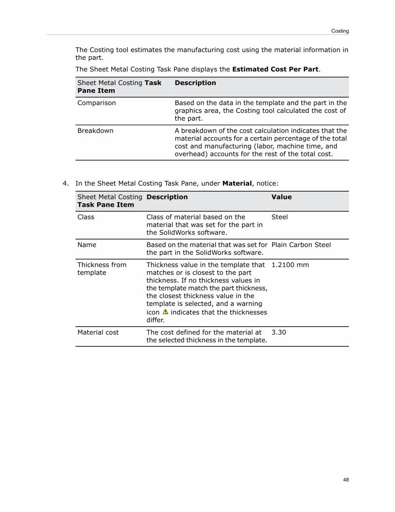
The Costing tool estimates the manufacturing cost using the material information inthe part.
The Sheet Metal Costing Task Pane displays the Estimated Cost Per Part.
DescriptionSheet Metal Costing TaskPane Item
Based on the data in the template and the part in thegraphics area, the Costing tool calculated the cost ofthe part.
Comparison
A breakdown of the cost calculation indicates that thematerial accounts for a certain percentage of the totalcost and manufacturing (labor, machine time, andoverhead) accounts for the rest of the total cost.
Breakdown
4. In the Sheet Metal Costing Task Pane, under Material, notice:
ValueDescriptionSheet Metal CostingTask Pane Item
SteelClass of material based on thematerial that was set for the part inthe SolidWorks software.
Class
Plain Carbon SteelBased on the material that was set forthe part in the SolidWorks software.
Name
1.2100 mmThickness value in the template thatmatches or is closest to the partthickness. If no thickness values inthe template match the part thickness,the closest thickness value in thetemplate is selected, and a warningicon indicates that the thicknessesdiffer.
Thickness fromtemplate
3.30The cost defined for the material atthe selected thickness in the template.
Material cost
48
Costing

5. The CostingManager in the FeatureManager design tree displays manufacturingfeatures like bends and cut paths that were recognized in the part. In theCostingManager, notice:
DescriptionManufacturing Process
Costs associated with manufacturing setups such assetting up machines to run a batch (lot) of parts.
Expand the Setup folder and hover over a setupcost to see how the cost is calculated.
Setup
There are five cut paths that are found for water jetcutting.
Expand the Cut Paths folder and hover over a cutpath to see how the cost is calculated. Select a cutpath to highlight the geometry in the model.
Cut Paths
Several bends are recognized, including a hem. Bendsare calculated as cost per bend.
Bends
The library features in the part are recognized.Library Features
Powder coating is a custom operation applied to thispart. It was set up in the template to apply to all parts.
Custom Operations
Anything that the Costing tool does not recognize oris not defined in the template.
No Cost Assigned
6. Keep this part and the Sheet Metal Costing Task Pane open for the next procedure.
Changing Costing InputsYou can perform “what if” studies to see how changes, such as lot size, might affect cost,without having to actually change the model. When you change Costing inputs, you cansee how the changes affect the cost immediately.
1. In the Costing Task Pane, under Quantity, set Lot size to 50.
49
Costing
2. Press Enter.Because Total number of parts is 100, you would need to run 2 lots to produce allof the parts. The Estimated Cost Per Part increases because you would incur 2setup charges, one for each lot.
Switching the Costing TemplateYou can determine how manufacturing operations affect the cost of your design. Forexample, you can compare costs of getting the part manufactured by different vendors.
In this example, you check the costs of a vendor that uses laser cutting instead of waterjet cutting.
In the Costing Task Pane, under Costing Template, selectsample_shm_metric_laser.You change the template to get a cost estimate from a laser cutting manufacturer.The Estimated Cost Per Part decreases, indicating it is cheaper to get the partmade at the laser cutting vendor.
Setting a BaselineYou can lock in the value of a design so you can compare future changes to the cost. Ifyou change the design later on, the cost will be compared to the locked cost.
In the Costing Task Pane, under Estimated Cost Per Part, click Set Baselineto lock the Current cost.
The Current cost is locked as Baseline and the button changes to . While thebaseline price is set, the part is rotated, flattened, and refolded.
Changing MaterialsNow you change the material and custom operations to see how these changes affect thecost with the new vendor.
1. In the Costing Task Pane, under Material, change Plain Carbon Steel to AISI 316Stainless Steel Sheet (SS).The Estimated Cost Per Part increases because stainless steel is more expensivethan plain carbon steel. However, because you are using stainless steel, powdercoating is no longer necessary and you can remove the powder coating customoperation.
2. In the CostingManager:
a) Expand Custom Operations .b) Right-click Powder Coating1 - Part and click Remove Custom Operation.The Estimated Cost Per Part decreases.
Modifying the Costing TemplateYou can modify the Costing template any time there are changes in cost structures. Forexample, if the price of steel increases, you can change the cost in the template.
50
Costing
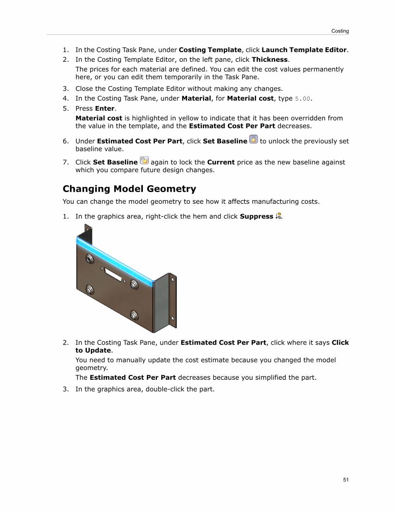
1. In the Costing Task Pane, under Costing Template, click Launch Template Editor.2. In the Costing Template Editor, on the left pane, click Thickness.
The prices for each material are defined. You can edit the cost values permanentlyhere, or you can edit them temporarily in the Task Pane.
3. Close the Costing Template Editor without making any changes.4. In the Costing Task Pane, under Material, for Material cost, type 5.00.5. Press Enter.
Material cost is highlighted in yellow to indicate that it has been overridden fromthe value in the template, and the Estimated Cost Per Part decreases.
6. Under Estimated Cost Per Part, click Set Baseline to unlock the previously setbaseline value.
7. Click Set Baseline again to lock the Current price as the new baseline againstwhich you compare future design changes.
Changing Model GeometryYou can change the model geometry to see how it affects manufacturing costs.
1. In the graphics area, right-click the hem and click Suppress .
2. In the Costing Task Pane, under Estimated Cost Per Part, click where it says Clickto Update.You need to manually update the cost estimate because you changed the modelgeometry.The Estimated Cost Per Part decreases because you simplified the part.
3. In the graphics area, double-click the part.
51
Costing

4. Double-click the flange depth, 35.
5. In the Modify dialog box, type 100 and click .
6. Click Rebuild (Standard toolbar) or Edit > Rebuild.The Estimated Cost Per Part increases.
Creating ReportsYou can create reports of Costing results. The detailed line items in the report make iteasy to see the affect of design decisions on cost.
At the bottom of the Costing Task Pane, click Generate Report .The report opens in Microsoft Word.
52
Costing

8Drawings and Detailing
This chapter includes the following topics:
• Align Balloons with Magnetic Lines• Automatically Insert Center Marks• Bend Tables• Highlighting Changed Dimensions• Customize Section View Label Fonts• Display Hole Wizard Hole Sizes Using Hole Type• Exploded Drawing Views• Improved GB Standard Templates• Initiate Bill of Materials Tool Without Preselecting a View• Open Assemblies and Subassemblies from Drawing Views• Ordering Balloons• Punch Tables• Reuse Letters from Deleted Views• Set Section View Arrows• Stacked Balloons
Align Balloons with Magnetic LinesYou can use magnetic lines to align balloons. You attach balloons to magnetic lines, chooseto space the balloons equally or not, and move the lines freely at any angle. The balloonsmaintain their alignment when the magnetic lines are not visible. You can insert magneticlines automatically when you use the Auto Balloon command. You can also insert balloonsbefore or after inserting magnetic lines.
With Magnetic LineWithout Magnetic Line
53

Inserting Magnetic Lines
To insert magnetic lines:
1. Open install_dir\samples\whatsnew\drawings\cover1.slddrw.
2. Click Magnetic Line (Annotation toolbar) or Insert > Annotations > MagneticLine.
3. Click to place the starting point of the magnetic line at the lower left of the drawingview.
4. Drag the other end point of the magnetic line straight up so that it is similar to thedrawing below, and click to place the end point.
The line snaps to horizontal, vertical, and 45° angle positions, but can be locatedat any angle.
5. In the Magnetic Line PropertyManager, click .
Attaching Balloons to Magnetic Lines
To attach balloons to magnetic lines, you can:
• Drag the balloon to the line. The cursor changes to a magnet symbol when theballoon snaps to the line. Balloons that are snapped to a magnetic line display with amagnet symbol when the magnetic line is visible.
54
Drawings and Detailing
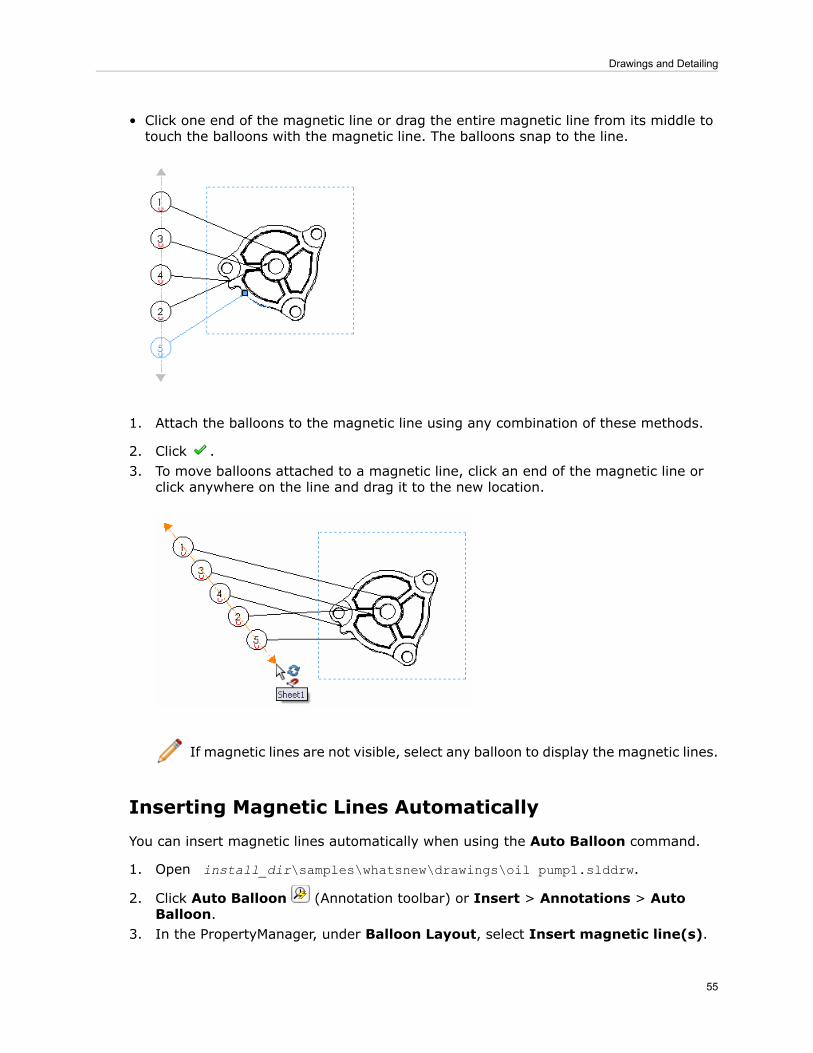
• Click one end of the magnetic line or drag the entire magnetic line from its middle totouch the balloons with the magnetic line. The balloons snap to the line.
1. Attach the balloons to the magnetic line using any combination of these methods.
2. Click .3. To move balloons attached to a magnetic line, click an end of the magnetic line or
click anywhere on the line and drag it to the new location.
If magnetic lines are not visible, select any balloon to display the magnetic lines.
Inserting Magnetic Lines Automatically
You can insert magnetic lines automatically when using the Auto Balloon command.
1. Open install_dir\samples\whatsnew\drawings\oil pump1.slddrw.
2. Click Auto Balloon (Annotation toolbar) or Insert > Annotations > AutoBalloon.
3. In the PropertyManager, under Balloon Layout, select Insert magnetic line(s).
55
Drawings and Detailing

4. Set the options.
5. Click .6. Drag the balloons to the magnetic line.
7. Click .
Automatically Insert Center MarksYou can automatically insert center marks for all holes, fillets, and slots in drawing views.Linear and circular patterns are recognized.
Center Marks Inserted AutomaticallyNo Center Marks
Inserting Center Marks Automatically
To automatically insert center marks:
1. In a drawing, click Center Mark (Annotation toolbar) or right-click and clickAnnotations > Center Mark.
2. In the PropertyManager, under Auto Insert:a) Select one or more of the following:
• For all holes
56
Drawings and Detailing

• For all fillets• For all slots
b) Set the options.
3. Select one or more drawing views.
4. Click to insert the center marks.
Bend TablesThere is a new bend table in SolidWorks 2012. You can insert the new bend table in theflat pattern view of sheet metal parts in drawings. Bend tables provide information aboutthe bends in the sheet metal body including tags, directions, angles, and inner radii. Youcan insert bend tables or bend notes, but not both.
57
Drawings and Detailing

Bend Table
Bend Notes
Inserting Bend Tables
Insert bend tables like other tables.
58
Drawings and Detailing
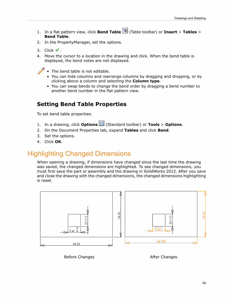
1. In a flat pattern view, click Bend Table (Table toolbar) or Insert > Tables >Bend Table.
2. In the PropertyManager, set the options.
3. Click .4. Move the cursor to a location in the drawing and click. When the bend table is
displayed, the bend notes are not displayed.
• The bend table is not editable.• You can hide columns and rearrange columns by dragging and dropping, or byclicking above a column and selecting the Column type.
• You can swap bends to change the bend order by dragging a bend number toanother bend number in the flat pattern view.
Setting Bend Table Properties
To set bend table properties:
1. In a drawing, click Options (Standard toolbar) or Tools > Options.2. On the Document Properties tab, expand Tables and click Bend.3. Set the options.4. Click OK.
Highlighting Changed DimensionsWhen opening a drawing, if dimensions have changed since the last time the drawingwas saved, the changed dimensions are highlighted. To see changed dimensions, youmust first save the part or assembly and the drawing in SolidWorks 2012. After you saveand close the drawing with the changed dimensions, the changed dimensions highlightingis reset.
After ChangesBefore Changes
59
Drawings and Detailing

Turning On Highlighting
To turn on highlighting for changed dimensions:
1. Click Options (Standard toolbar) or Tools > Options.2. On the System Options tab, click Colors.3. Select Use specified color for changed drawing dimensions on open.4. Click OK.
Specifying Highlighting Color
To specify the color for highlighting changed dimensions:
1. Click Options (Standard toolbar) or Tools > Options.2. On the System Options tab, click Colors.3. Under Color scheme settings, select Drawings, Changed dimensions.4. Click Edit.5. In the Color dialog box, select the color and click OK.6. Click OK.
Changes that Are Highlighted
With highlighting turned on, these changes are highlighted in drawings:
• Model changes that cause base number values to change• Imported dimensions where the tolerance type or value has changed in the model• Imported dimensions where there is a change in Add Parentheses or InspectionDimension
• Imported dimensions where there is a change in the Dimension Text (<DIM> bydefault)
To use this highlighting functionality, you must first save the part or assembly andassociated drawings in SolidWorks 2012. When you reopen the drawing, the highlightedchanges appear. If you hover over a changed dimension, a tooltip shows the previousdimension.
60
Drawings and Detailing

Changed Dimensions
Changed Tolerance
When you save the updated drawing, the highlighting functionality is reset.
Isolating Changed Dimensions
To isolate all changed dimensions:
61
Drawings and Detailing
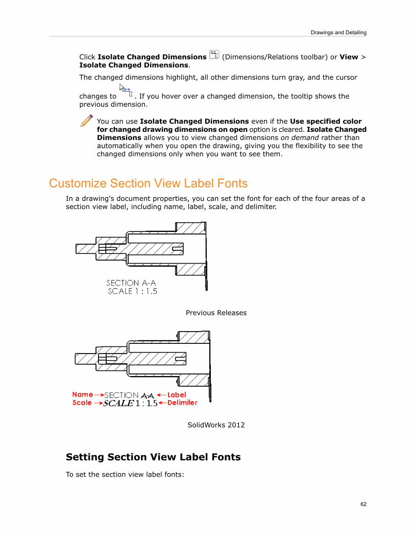
Click Isolate Changed Dimensions (Dimensions/Relations toolbar) or View >Isolate Changed Dimensions.
The changed dimensions highlight, all other dimensions turn gray, and the cursor
changes to . If you hover over a changed dimension, the tooltip shows theprevious dimension.
You can use Isolate Changed Dimensions even if the Use specified colorfor changed drawing dimensions on open option is cleared. Isolate ChangedDimensions allows you to view changed dimensions on demand rather thanautomatically when you open the drawing, giving you the flexibility to see thechanged dimensions only when you want to see them.
Customize Section View Label FontsIn a drawing's document properties, you can set the font for each of the four areas of asection view label, including name, label, scale, and delimiter.
Previous Releases
SolidWorks 2012
Setting Section View Label Fonts
To set the section view label fonts:
62
Drawings and Detailing

1. In a drawing, click Options (Standard toolbar) or Tools > Options.2. On the Document Properties tab, expand View Labels and click Section.3. Under Label options, click Font for each area, select the font and parameters in the
Choose Font dialog box, then click OK.4. Click OK to close the Document Properties - Section dialog box.
Use the Options dialog box to set the section view label fonts so that the fonts are usedin newly created section views. You can override the font of any specific part of the labelby double-clicking the label section and selecting a font and parameters from theFormatting toolbar.
Display Hole Wizard Hole Sizes Using Hole TypeYou can display ANSI inch hole sizes in hole tables using letters or numbers (for example,A or #40). This option displays holes created with the Hole Wizard tool with the samesizes as the Hole Specifications in the Hole Wizard tool.
Not using hole typeUsing hole type
Displaying Sizes with Letters and Numbers
To display the ANSI inch sizes as they appear in the Hole Wizard tool:
1. In a drawing, click Options (Standard toolbar) or Tools > Options.2. On the Document Properties tab, expand Tables and click Hole.3. Under Scheme, select Show ANSI inch letter and number drill sizes.
4. Click .
Switching the Display
You can switch the display of sizes in a hole table.
1. Select the hole table.2. In the Hole Table PropertyManager, under Scheme, select or clear Show ANSI inch
letter and number drill sizes.
3. Click .
63
Drawings and Detailing
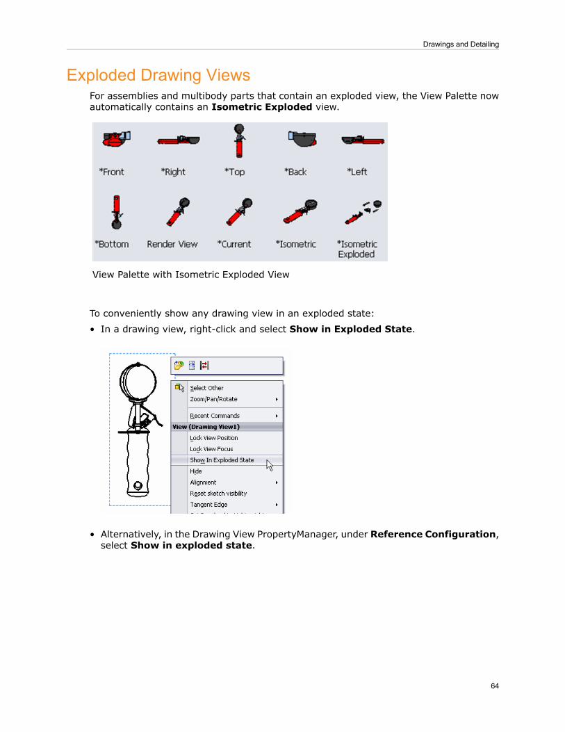
Exploded Drawing ViewsFor assemblies and multibody parts that contain an exploded view, the View Palette nowautomatically contains an Isometric Exploded view.
View Palette with Isometric Exploded View
To conveniently show any drawing view in an exploded state:
• In a drawing view, right-click and select Show in Exploded State.
• Alternatively, in the Drawing View PropertyManager, under Reference Configuration,select Show in exploded state.
64
Drawings and Detailing

Exploded Drawing View
Improved GB Standard TemplatesThe GB standard templates have been updated. New templates are available for parts,assemblies, and drawings.
Initiate Bill of Materials Tool Without Preselecting a ViewYou can insert a bill of materials (BOM) on a different sheet than the sheet where theBOM is defined.
To switch drawing sheets while the BOM is attached to the pointer:
65
Drawings and Detailing

1. In a drawing with multiple sheets, click Bill of Materials (Table toolbar) or Insert> Tables > Bill of Materials.
2. Click in a drawing view to select it.3. In the Bill of Materials PropertyManager, set the options.
4. Click .5. With the pointer attached to the BOM, at the bottom of the graphics area, click a sheettab.
6. Move the pointer to locate the bill of materials and click.
To create a bill of materials from a drawing view on an inactive drawing sheet:
1. In a drawing with multiple sheets, click Bill of Materials (Table toolbar) or Insert> Tables > Bill of Materials.
2. Select the FeatureManager design tree tab to activate it.
3. Select an inactive view from the FeatureManager design tree.
4. In the Bill of Materials PropertyManager, set the options.
5. Click .6. With the pointer attached to the BOM, at the bottom of the graphics area, click a sheettab.
7. Move the pointer to locate the bill of materials and click.
Open Assemblies and Subassemblies from Drawing ViewsIn addition to opening parts from the context toolbar in drawing views, you can opentop-level assemblies or subassemblies directly from the context toolbar, if the parts are
66
Drawings and Detailing

contained in subassemblies. If the parts are only contained in assemblies, you can openthe parts or assemblies.
Activating the Option
To activate the option to open parts, assemblies, and subassemblies from the contexttoolbar:
1. Click Tools > Customize.2. On the Toolbars tab, under Context toolbar settings, select Show in shortcut
menu.3. Click OK.
Opening the Component From the Context Toolbar
To open parts, assemblies, or subassemblies from the context toolbar:
In a drawing view, click on a component.
Icons in the Context ToolbarComponentType
Open PartPart
Open Assembly and Open PartAssembly
Open Assembly , Open Subassembly , and Open PartSubassembly
Opening the Component From the Shortcut Menu
To open parts, assemblies, or subassemblies from the shortcut menu:
In a drawing view, right-click on a component.
ActionComponentType
Under Component, select Open Part.Part
Under Component, select Open Part, or under View, select OpenAssembly.
Assembly
Under Component, select Open Part, or under View, select OpenAssembly or Open Subassembly.
Subassembly
Ordering BalloonsIn addition to creating balloons, stacked balloons, and auto balloons following the assemblyorder, you can create balloons and number them sequentially. For balloons, auto balloons,
67
Drawings and Detailing

or stacked balloons, you can also control the direction of the ordering (for example, leftto right or right to left for a linear arrangement), as well as which balloon is designatedas the first balloon.
To order balloons sequentially:
• A bill of materials must exist in the drawing. Ordering balloons sequentially reordersthe bill of materials.
• You must link the balloons to the bill of materials. When you create a new bill ofmaterials, the balloons are automatically linked to it. In cases where they are not linked,you can link them by right-clicking in the drawing view and clicking Properties. In theDrawing View Properties dialog box, on the View Properties tab, under Balloons,select Link balloon text to specified table, and click OK.
• You must add the balloons to the drawing. Existing balloons cannot be reordered.
In this example, you:
• Insert a bill of materials.• Use Auto Balloons to insert balloons following the assembly order.• Reorder the balloons sequentially.• Designate a balloon as the first balloon.
Inserting a Bill of Materials
To insert a bill of materials:
1. Open install_dir\samples\whatsnew\drawings\Ordering_balloons.slddrw.
2. In the drawing view, click Bill of Materials (Table toolbar) or Insert > Tables> Bill of Materials.
3. In the PropertyManager, under BOM Type, select Parts only.
4. Click .5. Move the pointer to the lower left of the drawing and click to place the bill of materials.
68
Drawings and Detailing

Inserting Balloons Following Assembly Order
1. In a drawing view of the assembly, click AutoBalloon (Annotation toolbar) orInsert > Annotations > Auto Balloon.
2. In the PropertyManager, under Item Numbers, select Follow assembly order .
3. Click .
The balloons appear as shown:
The numbered sequence of the balloons follows the order in the assembly FeatureManager.
Numbering the Balloons Sequentially
To insert the balloons and renumber them sequentially starting with 1:
1. Open install_dir\samples\whatsnew\drawings\Ordering_balloons.slddrw.2. If necessary, insert the bill of materials. See Inserting a Bill of Materials on page
68.
3. In the drawing view of the assembly, click AutoBalloon (Annotation toolbar) orInsert > Annotations > Auto Balloon.
4. In the PropertyManager, under Item Numbers, select Order sequentially .
5. Click .
The balloons are reordered so that the top left balloon starts with 1 and continuessequentially, in a clockwise direction, through 9. The bill of materials updates to matchthe reordered sequence.
69
Drawings and Detailing

Setting the First Balloon
The balloons are numbered sequentially, starting with 1 at the top left of the drawing.To start the numbering at the bottom left of the drawing with 1 and continue clockwise:
1. Open install_dir\samples\whatsnew\drawings\Ordering_balloons.slddrw.2. If necessary, insert the bill of materials. See Inserting a Bill of Materials on page
68.3. In the drawing view of the assembly, click Insert > Annotations > Auto Balloon.4. In the PropertyManager, under Item Numbers, select Order sequentially.5. Under Item Numbers, click First item.6. Click the bottom left balloon to use as the first item.
7. Click .
70
Drawings and Detailing
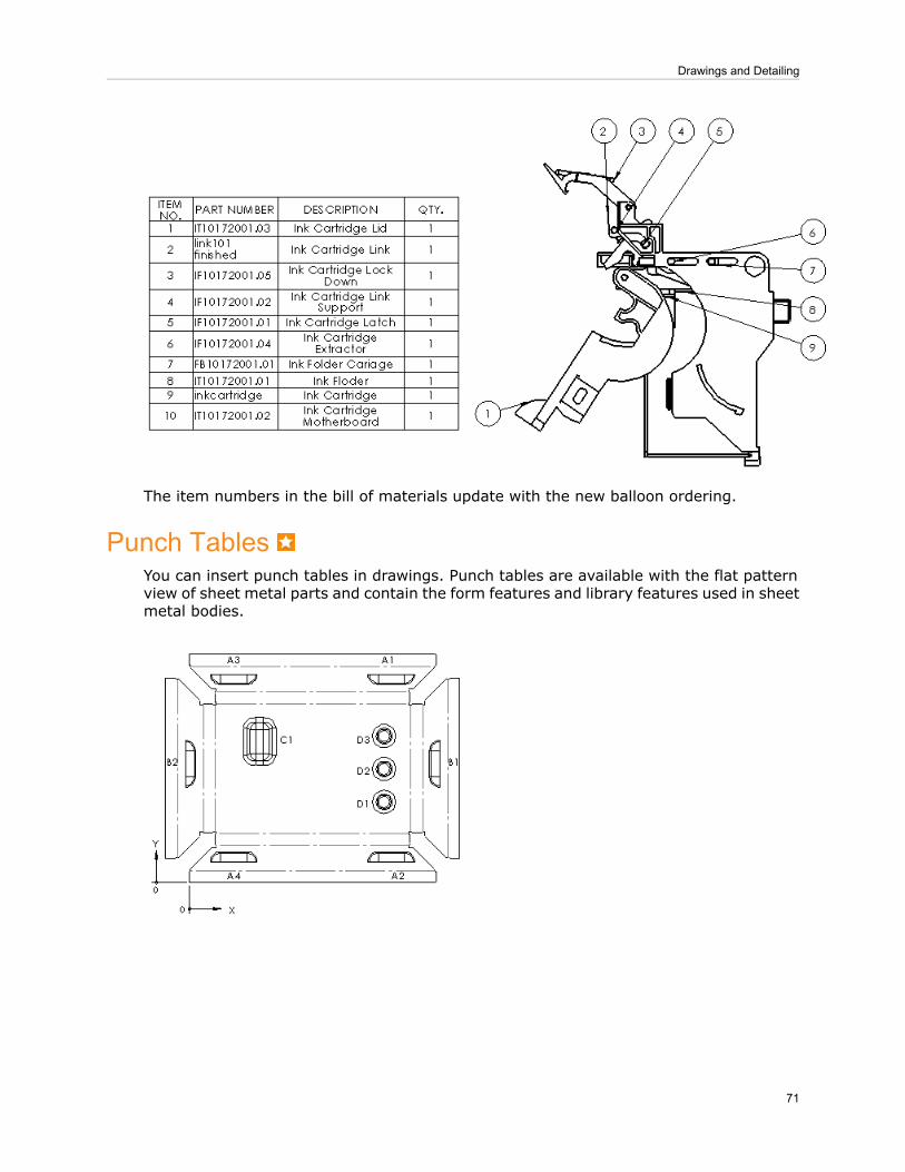
The item numbers in the bill of materials update with the new balloon ordering.
Punch TablesYou can insert punch tables in drawings. Punch tables are available with the flat patternview of sheet metal parts and contain the form features and library features used in sheetmetal bodies.
71
Drawings and Detailing

A punch table includes:
Annotation added to each punch feature in the flat patternTag
Distance from X-axis to the point of insertion of the toolX Location
Distance from Y-axis to the point of insertion of the toolY Location
Property of the forming tool/library feature used in thecomponent
Punch ID
Number of times form/library feature is used in the flat patternQuantity
Angle between X-axis and the toolAngle
To learn how to create Punch IDs, see Creating Punch IDs on page 142.
For information on inserting a Punch Table, see Inserting a Punch Table on page 142.
Reuse Letters from Deleted ViewsIf you delete a derived view (section, detail, or auxiliary) from a drawing, you can reusethe letters from the deleted view in the drawing without manually relettering the views.This option is off by default.
In previous releases, if you deleted a derived view, such as a section view, and thencreated a new section view, the lettering would use the next sequential letter. For example,if you deleted Section A-A from a drawing view and then created a new section view,the new label would be Section B-B. You can now reuse the letters from deleted viewsautomatically, so the newly created section would be Section A-A.
Reusing Letters from Deleted Views
1. In a drawing, click Options (Standard toolbar) or Tools > Options.2. On the System Options tab, click Drawings.3. Select Reuse view letters from deleted auxiliary, detail, and section views.4. Click OK.
72
Drawings and Detailing

Set Section View ArrowsYou can set the arrow type for section views independently of the arrow type fordimensions. Previously, section views used the same arrow type as dimensions.
In this example, the dimensions use arrows and the section view uses arrows.
Setting Arrow Types
To set the arrow type for section views:
1. In a drawing, click Options (Standard toolbar) or Tools > Options.2. On the Document Properties tab, expand View Labels and click Section.3. Under Section/view size, select the style.4. Click OK.
Stacked BalloonsThe stacked balloon functionality for horizontal lines is improved. You have more controlover the appearance of stacked balloons including automatic and manual extension ofhorizontal lines to accommodate text, and horizontal text justification. Also, when youdrag a stacked balloon annotation, the position of the stack flips to the other side whennecessary.
In previous releases, if you created stacked balloons with horizontal lines, they couldappear as shown:
73
Drawings and Detailing
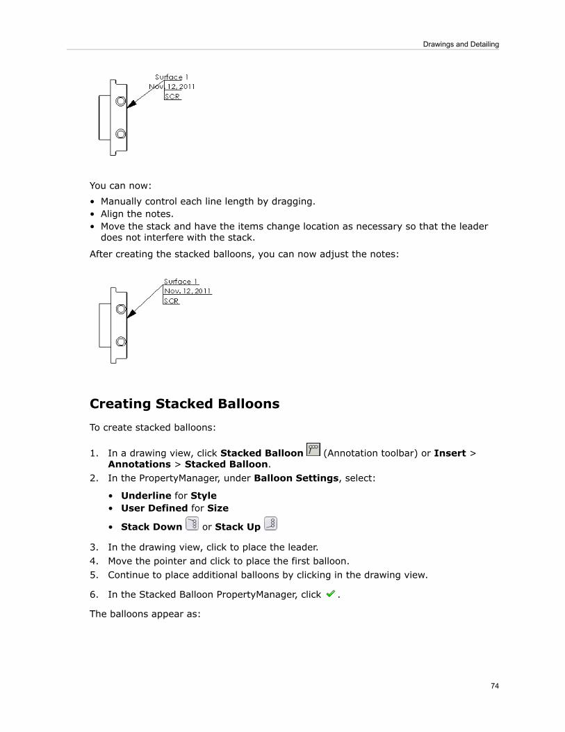
You can now:
• Manually control each line length by dragging.• Align the notes.• Move the stack and have the items change location as necessary so that the leaderdoes not interfere with the stack.
After creating the stacked balloons, you can now adjust the notes:
Creating Stacked Balloons
To create stacked balloons:
1. In a drawing view, click Stacked Balloon (Annotation toolbar) or Insert >Annotations > Stacked Balloon.
2. In the PropertyManager, under Balloon Settings, select:
• Underline for Style• User Defined for Size
• Stack Down or Stack Up
3. In the drawing view, click to place the leader.4. Move the pointer and click to place the first balloon.5. Continue to place additional balloons by clicking in the drawing view.
6. In the Stacked Balloon PropertyManager, click .
The balloons appear as:
74
Drawings and Detailing
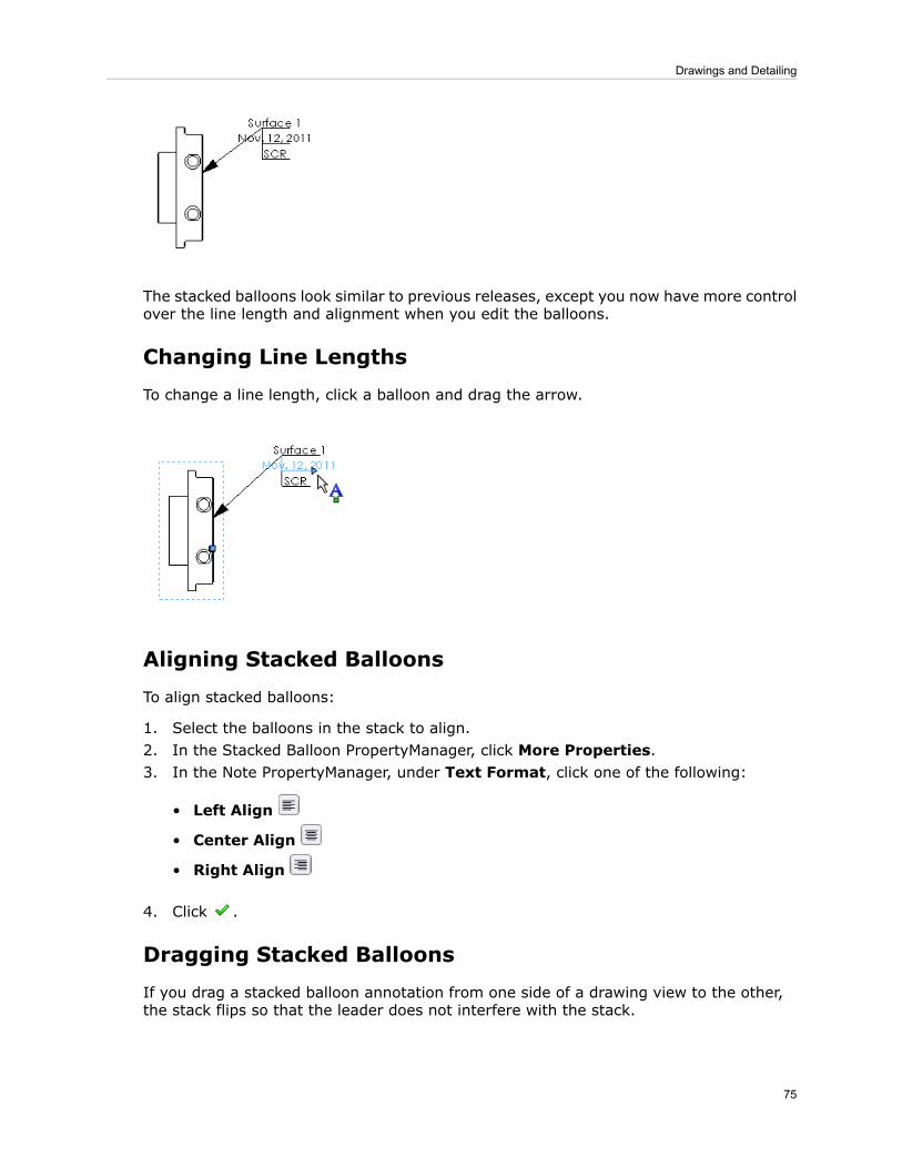
The stacked balloons look similar to previous releases, except you now have more controlover the line length and alignment when you edit the balloons.
Changing Line Lengths
To change a line length, click a balloon and drag the arrow.
Aligning Stacked Balloons
To align stacked balloons:
1. Select the balloons in the stack to align.2. In the Stacked Balloon PropertyManager, click More Properties.3. In the Note PropertyManager, under Text Format, click one of the following:
• Left Align
• Center Align
• Right Align
4. Click .
Dragging Stacked Balloons
If you drag a stacked balloon annotation from one side of a drawing view to the other,the stack flips so that the leader does not interfere with the stack.
75
Drawings and Detailing

SolidWorks 2012Previous releases
76
Drawings and Detailing
9eDrawings
eDrawings Professional is available in SolidWorks Professional and SolidWorks Premium.
This chapter includes the following topics:
• Bills of Materials• File References
Bills of MaterialsWhen you open a file in SolidWorks eDrawings
®that has a hidden bill of materials (BOM),
the BOM remains hidden.
File ReferencesWhen you open a SolidWorks document, eDrawings checks the document’s file referencesto see if the references have been updated. This helps you determine if the document isout of date.
If eDrawings cannot determine whether file references are up to date, or if it confirmsthat the file references are not up to date, a watermark is displayed. You can click thewarning icon in the bottom of the eDrawings window and click any of the following:
• Check if File is Out of Date• Always Show Warning Watermark• Show Warning Watermark for this document only
To use the file reference checking for standalone eDrawings installations, you mustdownload and install the SolidWorks Document Manager when prompted.
The Mac OS®version of eDrawings cannot check file references.
77

10Equations
SolidWorks provides a completely redesigned dialog box for creating and editing equations,global variables and dimensions. This release contains a host of new options that improve theworkflow and efficiency for building and managing equations. Now you can perform all tasksrelated to equations in one dialog box without needing to open additional windows. You canalso create equations and global variables directly in the Modify dialog box for dimensions.
Enhancements to functionality include:
• automatic determination of the proper solve order of equations, to avoid circular referencesand reduce equation troubleshooting.
• automatic solving of cases that previously required mutiple rebuilds.• an automatic rebuild option, to display graphically the impact of each change to equations.• the ability to create permanent links to external text files, to make these files easilyaccessible.
• support for instance numbers, to provide unambiguous references to components in anassembly.
• a new measure option to speed up the process of creating reference dimensions.• and new syntax using if statements and the ability to use the =, <=, and => conditionaloperators.
Other enhancements include type-ahead capabilities and drop-down lists to speed up enteringequations, and automatic syntax checking to increase accuracy.
This chapter includes the following topics:
• Accessing the Equations Dialog Box• Three Views of Equations• Interface Enhancements• Functionality Enhancements• Create and Edit Equations in the Equations Dialog Box• Export, Import, and Link Equations to a File• Create Equations in the Modify Dialog Box• Equations and Configurations• Use Equations
Accessing the Equations Dialog BoxDisplay the Equations, Global Variables and Dimensions dialog box by doing one of thefollowing:
• Click Equations (Tools toolbar).• Click Tools > Equations.
78

• Right-click the Equations folder in the FeatureManager design tree, and selectManage Equations.
Three Views of EquationsThe Equations, Global Variables and Dimensions dialog box offers three views. Each viewshows a different combination and sequence of equations, global variables and dimensionsto help you perform tasks such as finding a specific equation, viewing all dimensions usedin a part, and changing the order in which equations are solved.
To select a view:
• Click the Equations View to see all global variables and equations for dimensionsand features.
• Click the Dimensions View to see all global variables, equations, and dimensionsused in the active part or assembly, whether they are associated with an equation ornot.
• Click the Ordered View to see global variables and equations in the order they aresolved, and to see suppressed equations.
Equations ViewThe Equations View displays all global variables, equations to suppress features, andother equations for the part or assembly, grouped in those three categories.
In this view you can add new global variables and equations. You can also edit, deleteand suppress existing ones, and add comments.
Dimensions ViewThe Dimensions View displays all the dimensions used in the active part or assembly,including those with a set value and those determined by equations. This view makes iteasy to rename or change the values of several dimensions.
Dimensions with a set value are visible only in this view, not in the Equations View or theOrdered View.
There are two versions of the Dimensions View, one for parts, and one for assemblies.
In the Dimensions View for a part, you can:
79
Equations
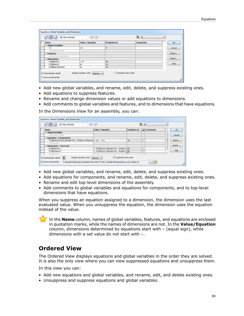
• Add new global variables, and rename, edit, delete, and suppress existing ones.• Add equations to suppress features.• Rename and change dimension values or add equations to dimensions.• Add comments to global variables and features, and to dimensions that have equations.
In the Dimensions View for an assembly, you can:
• Add new global variables, and rename, edit, delete, and suppress existing ones.• Add equations for components, and rename, edit, delete, and suppress existing ones.• Rename and edit top-level dimensions of the assembly.• Add comments to global variables and equations for components, and to top-leveldimensions that have equations.
When you suppress an equation assigned to a dimension, the dimension uses the lastevaluated value. When you unsuppress the equation, the dimension uses the equationinstead of the value.
In the Name column, names of global variables, features, and equations are enclosedin quotation marks, while the names of dimensions are not. In the Value/Equationcolumn, dimensions determined by equations start with = (equal sign), whiledimensions with a set value do not start with =.
Ordered ViewThe Ordered View displays equations and global variables in the order they are solved.It is also the only view where you can view suppressed equations and unsuppress them.
In this view you can:
• Add new equations and global variables, and rename, edit, and delete existing ones.• Unsuppress and suppress equations and global variables.
80
Equations

• Change the order of the equations and global variables (if the Automatic solve orderoption is clear).
Interface EnhancementsThe following enhancements are available from all views in the Equations, Global Variablesand Dimensions dialog box.
Sort and Filter EquationsNew sorting and filtering capabilities make it much easier to find equations and globalvariables and see how they are related. Sorting and filtering work in all views of theEquations dialog box.
Sorting
1. Select any view in the Equations dialog box.2. Click any column heading. A small arrow appears on the right side of the cell.
3. Click once to sort in ascending order.4. Click a second time to sort in descending order.5. Click a third time to return the rows to the original order.
Creating a Filter
1. Select any view in the Equations dialog box.2. Enter your filter criteria in the Filter field and press Enter.
The filter returns results that contain characters in any column. For example, enteringov might return the global variable overall length, an equation that includes
81
Equations
overall length as one of its terms, and another equation that has a comment Don’toverlook the ring.
3. Continue to enter criteria until you find the desired global variable, feature, or equation.4. Clear the filter by clicking X in the Filter field.
Selecting Multiple RowsYou can select multiple rows in the Equations dialog box to perform the same task on allof the equations, for example to suppress, unsuppress, or delete several equations atonce.
To select multiple rows, position the cursor in the left-most column of a row. A smallarrow appears in the cell.
Do one of the following:
• Select several rows by dragging the cursor up or down in the left-most column.• Ctrl + click the left-most column in one or more rows.• Shift + click the left-most column in the last of a series of rows.
Then right-click to display a menu and select one of the available tasks.
Undo and RedoYou can undo and redo steps by clicking Undo and Redo at the top of the Equations dialogbox.
Undo and Redo are available in all views. You can undo and redo any edits thatyou perform since invoking the dialog box.
If you change configurations while in the Equations dialog box, Undo and Redo listsare reset. Prior steps cannot be undone or redone.
Type-Ahead EntryWhen you enter an equation in the Equations dialog box and type in one or morecharacters, a type-ahead feature displays a drop-down list showing all global variables,mathematical functions, and file properties that start with those characters. You can selectan entry from the drop-down list instead of typing the entire entry.
Syntax Checking with Color CodingThe Equations dialog box includes syntax checking to avoid errors and reduce the timeyou spend on troubleshooting mistakes.
When you enter text into the Name and Value/Equation columns, the text color variesdepending on these conditions:
• Valid global variables, features and dimensions appear in blue.• Incomplete and invalid text displays in red.• Potentially invalid text, for example text that may include a circular reference, isdisplayed in yellow. A yellow warning icon is also displayed in the row.
• Valid operators, functions, and other inputs appear in black.
82
Equations

Positioning the cursor over the yellow or red text displays a warning message. Clickingthe warning icon displays a What’s Wrong window describing the issue or error.
Navigate Table CellsIn the Equations dialog box, you can navigate from cell to cell, across rows, and columnsusing the following keys:
• Enter• Shift + Enter• Tab• Shift + Tab
Functionality EnhancementsThese sections describe several of the functionality enhancements to the Equations, GlobalVariables and Dimensions dialog box.
Automatic Solve Order OptionYou can use the Automatic Solve Order option to automatically sequence the equationsin an order determined by the software to produce accurate results.
When you select the Automatic Solve Order option, SolidWorks identifies dependenciesand orders equations so that independent equations are executed before dependentequations. That is, if equation B is defined as a function of equation A, then equation Aalways needs to be solved first.
For example, in the following two equations, SolidWorksevaluates“D2@Sketch1@part_inside.Part” first, so it can safely be used as a variablein the equation for "D1@Sketch1@part_outside.Part".
“D1@Sketch1@part_outside.Part” = “D2@Sketch1@part_inside.Part” + 2
“D2@Sketch1@part_inside.Part” = “Side” - 6
You can view the solve order in the Ordered View of the Equations dialog box.
You must clear this option to manually change the order of the equations
Automatic Rebuild OptionYou can use the Automatically rebuild option to automatically rebuild the model eachtime you change an equation.
This option makes it easier to visualize the impact of each change you make to equations.
Linking to a Text FileIn the Equations dialog box, you can link to an external text file that contains equationsand global variables. You can use this option in place of the import and export functions
83
Equations

when you want to set up an ongoing link. However, you cannot use it for a one-timeimport or export.
Suppressing EquationsYou can suppress equations and global variables from all views in the Equations dialogbox. You can only view and unsuppress them in the Ordered View.
You can suppress equations and global variables to help you troubleshoot equations.
You can also suppress equations so that different equations can be applied to differentconfigurations of a part or assembly.
You can edit suppressed equations and global variables in the Ordered View, but thechanges do not take affect in the model until the equation or variable is unsuppressed.
Components with Multiple InstancesIn this release the Equations dialog displays components that are referred by uniqueinstance numbers. You can apply equations to specific instances. This ensures there isno ambiguity about the instance referenced in each equation.
For example, the following equations refer to the same part BigAndSmall, which hasinstances <1> and <2>. In the Equations dialog, you can select which instance to applyto an equation.
"HoleWidth@Sketch1" = "Width@Sketch1@BigAndSmall<2>.Part"
"HoleDepth@Cut-Extrude1" = "Depth@Boss-Extrude1@BigAndSmall<1>.Part" / 2.0
"HoleWidthOffset@Sketch1" = ("Width@Sketch1@BigAndSmall<1>.Part" / 2) -("Width@Sketch1@BigAndSmall<2>.Part" / 2)
The instance number is always enclosed in < > angle brackets.
In previous releases, the software did not display the instance number. Instead, it selectedthe latest instance and action that was available in memory.
The Measure OptionYou can use the Measure... option to create a driven dimension or reference dimensionthat is based on a measurement of the part or assembly.
The value of this dimension might change if the model changes. For example, if anequation includes a measurement of the height of a part, and that height is doubled,then the equation evaluates to twice the previous value.
The Measure option is available from all three views of the Equations dialog box, andalso from the Modify dialog box.
You can select the Measure... option from the flyout menu when you are in theValue/Equation column creating or editing global variables, features, equations, anddimensions. It appears in the flyout menu whenever a measurement is valid.
84
Equations

Create and Edit Equations in the Equations Dialog BoxYou can use the Equations dialog box to create, edit, suppress, unsuppress and deleteequations. Global variables and equations are available in one place, and flyout menushelp you create global variables and equations more quickly and accurately.
Adding an Equation
To add an equation in the Equations View:
1. Do one of the following:
• Click Equations (Tools toolbar).• Click Tools > Equations.• Right-click the Equations folder in the FeatureManager design tree, and selectManage Equations.
2. Select the Equations View .3. In the Equations section, click an empty cell in the Name column.4. Click a dimension in the graphics area.
The SolidWorks software does the following:
• Propagates the dimension name to an empty cell in the Name column and enclosesit in quotation marks.
• Moves the cursor to the Value/Equations column and inserts = (equal sign).• Displays a flyout menu with options for starting the equation.
5. After = (equal sign), add a term to the equation by doing one of the following:
• Type a number or a conditional statement.• Select a Global Variable, Function or File Property from the flyout menu.• Select Measure ... from the flyout menu and use the Measure Tool to create theterm.
A appears in the cell to indicate that the syntax is valid.
6. Type + (plus), - (minus) or another mathematical symbol.7. Add another term to the equation.
8. When the equation is complete, click .The solution to the equation appears in the Evaluates to column and the cursormoves to the next cell in the Comments column.
9. Add comments to document your design intent.10. Click OK to close the dialog box.
Editing an Equation
When editing, keep the following in mind:
• Dimension names must be enclosed in quotes.
85
Equations

• Equations are solved left to right (that is, the dimension on the left is driven by thevalue on the right).
• Equations are solved in the order in which they appear in the Ordered view. You canchange the order, if necessary.
1. Do one of the following:
• Click Equations (Tools toolbar).• Click Tools > Equations.• Right-click the Equations folder in the FeatureManager design tree, and selectManage Equations.
2. Select the Equations View .3. Select an equation, global variable or dimension.4. Edit the entry.
Use the type-ahead entry, flyout menu of Equations, Global Variables, Functionsand File Properties, and syntax checking to edit the equation.
If you make a mistake, click Undo to clear each consecutive edit. You canclear one edit each time you click Undo.
5. Click OK to close the dialog box.
Suppressing an EquationYou can suppress equations and global variables to help you troubleshoot equations. Youcan also suppress equations so that different equations can be applied to differentconfigurations of a part or assembly.
1. Do one of the following:
• Click Equations (Tools toolbar).• Click Tools > Equations.• Right-click the Equations folder in the FeatureManager design tree, and selectManage Equations.
2. Select the Equations View .3. Select the row containing the global variable or feature or equation you want to
suppress and right-click.A flyout menu displays the choice to suppress the item.
4. From the flyout menu, select Suppress. If you are working on a part or assemblywith multiple configurations, you can suppress:
• This Configuration• All Configurations• Specify Configurations
86
Equations

To unsuppress, select the Ordered View , select the row and right-click. From theflyout menu, select Unsuppress.
Deleting an Equation
To delete a global variable or an equation from any view:
1. Select one or more rows, containing the global variables or equations you want todelete and right-click.
2. From the flyout menu, select Delete or the Delete key.3. Click OK to close the Equations dialog box.
Deleting a global variable or equation may cause other equations that include the globalvariable or equation to become invalid. Syntax checking identifies this situation immediatelyby displaying a warning symbol and displaying the deleted term in red anywhere it appearsin the Value/Equation field. This can dramatically reduce the time needed to detect andtroubleshoot orphaned equations.
Using the Measure Option
To use the Measure option when creating or editing an equation:
1. Do one of the following:
• Click Equations (Tools toolbar).• Click Tools > Equations.• Right-click the Equations folder in the FeatureManager design tree, and selectManage Equations.
2. Select the Equations View .3. In the Equations section, click an empty cell in the Name column.4. Click a dimension in the graphics area.
The SolidWorks software does the following:
• Propagates the dimension name to the empty cell in the Name column and enclosesit in quotation marks.
• Moves the cursor to the Value/Equations column and inserts = (equal sign).• Displays a flyout menu with options for starting the equation.
5. In the flyout menu, select Measure….6. In the graphics area, select the references to create a reference dimension.7. In the Dimension PropertyManager, make any changes to the parameters of the
dimension and click .
The new dimension appears as part of the equation.
87
Equations
Changing Dimensions by ConfigurationIf a part has several configurations, you can decide whether changes to a dimension willaffect one configuration, all configurations, or selected configurations.
To specify configurations affected by a change in dimensions:
1. Select the Dimensions View in the Equations dialog box.2. Edit the Value/Equations field for the dimension.
If the dimension applies to more than one configuration, a configuration icon appearsin the column.
3. From the flyout menu, select from the following choices:
• This Configuration• All Configurations• Specify Configurations
4. Click OK to close the dialog box.
Export, Import, and Link Equations to a FileEnhancements in this release give you much more control over importing, exporting, andlinking equations.
You can export all equations or selected equations to a text file, and import all equationsor selected equations from a text file. The text file can be shared with other parts andassemblies that use the same global variables and equations.
You can create permanent links with text files using the Link to external file, so thatchanges to the text file are propagated to the model.
The Link to external file always creates a link with the external file. The Export andImport processes include options for one-time exports and imports without a link.
Linking to External Files
To export equations using Link to external file in the Equations dialog box:
1. In any of the views, select the Link to external file check box.2. In the Link Equations dialog box:
a) Select Create new file.b) Specify a name and location for the text file.c) In the Equations column, clear the check mark for any equation you do not wantto export.
d) Click Link.
The equations are saved in a text file. The text file is available to import into other partsand assemblies.
88
Equations

Then in the Equations dialog box:
• A Link column appears and indicates which equations are linked to the file.• The Link to external file check box is selected and the path to the external file appears.
Subsequent changes to the text file will be propagated to the model.
Equations and global variables that are linked to an external file cannot be modifiedin the Equations dialog box. They must be edited in the external file. To remove thelink and modify an individual equation in the dialog box, clear the check box for thatequation in the Link column.
You can always access the external file by clicking Open linked file .
Exporting Equations
To export equations to a text file:
1. Define equations in the Equations dialog box.2. Click Export.3. In the Save As dialog box:
a) Specify a name and location for the text file.b) Enter a description of the file.c) Click Save.
4. In the Export Equations dialog box:a) Select or clear Link to file.b) In the Equations column, clear the check mark for any equations you do not wantto export.
c) In the Link column, clear the check mark for any equations you do not want tolink to the external file.
d) Click Export.
The equations are saved in a text file. The text file is available to import into other partsand assemblies.
89
Equations

If Link to File was selected, changes you make in the text file are propagated to themodel. Then in the Equations dialog box:
• A Link column appears and indicates which equations are linked to the file.• The Link to external file check box is selected and the path to the external filedisplays.
Equations and global variables that are linked to an external file cannot be modifiedin the Equations dialog box. They must be edited in the external file. To break thelink and modify an equation in the dialog box, uncheck the box for that equation inthe Link column.
Importing EquationsYou can import equations from a text file into a part or assembly.
1. In the part or assembly, click Tools > Equations.2. In the Equations dialog box, click Import.3. In the Open dialog box:
a) Select the text file.b) Click Open.
4. In the Import Equations dialog box:a) Select or clear Link to File.b) In the Equations column, clear the check mark for any equation you do not wantto import.
c) In the Link column, clear the check mark for any equation you do not want to linkto the external file.When Link to file is selected, changes you make in the text file update theequations and variables in the model.
d) Click Import.
The equations from the text file are imported into the model.
If Link to File was selected, changes you make in the text file are propagated to themodel. Then in the Equations dialog box:
• A Link column appears and indicates which equations are linked to the file.• The Link to external file check box is selected and the path to the external filedisplays.
Equations and global variables that are linked to an external file cannot be modifiedin the Equations dialog box. They must be edited in the external file. To remove thelink and modify an equation in the dialog box, clear the box for that equation in theLink column.
Creating Equations in External FilesYou can create equations in a text file and then import them into one or more parts andassemblies.
1. Open a text file in an application such as Notepad.
90
Equations
2. Type equations in the same format as used in the Equations dialog box.For example, you might define a global variable, base, and define two relateddimensions."base" = 20"D1@Boss-Extrude1" = "base" + 10"D2@Sketch1" = ("base"*3) + 5
3. Save the text file.
You can import the text file into one or more parts and assemblies with the Equationsdialog box. You can choose to link models to the text file, so that changes you make inthe text file update the equations and variables in the models.
Changing Equations Through a Linked FileYou can change equations in a linked text file and see the changes reflected in a part.
To change equations using a linked text file:
1. At the bottom of the Equations dialog box, click Open linked file from any view.The text file opens.
2. Change one or more of the equations.3. Save the text file.4. In the Equations dialog box, you can link and unlink individual equations by selecting
and clearing the check boxes in the Links column.
5. Click Rebuild to see the changed equations.
Create Equations in the Modify Dialog BoxWhen working on a model, you can enter equations and global variables directly in theModify dialog box for dimensions. You do not have to open the Equations, Global Variables,and Dimensions dialog box to create an equation for a component.
The equations and global variables that you create in the Modify dialog box are reflectedin the Equations dialog box.
Creating a Global Variable
To create a global variable in the Modify dialog box for a dimension:
1. In the model, double-click a dimension.The Modify dialog box for dimensions displays, showing the name of the dimensionand the current value.
2. In the second line of the Modify dialog box, enter = (equal sign). Enter the nameof a new global variable and enclose it in quotation marks.
The text displays in yellow and the Create Global Variable button appears nextto the name.
91
Equations

3. Click the Create Global Variable button, or hit Enter, or click and Yes.
The global variable button appears to the left side of the equation. Clicking theglobal variable button causes the entry to toggle between the global variable nameand the evaluated value.
4. Click to confirm.
Changes to the value of the global variable update all equations and variables in themodel that reference that global variable.
The next time you open the Equations dialog box it will include:
• The new global variable.• The equation making the dimension equal to the global variable.
Creating an Equation
To create an equation in the Modify dialog box for a dimension:
1. In the model, double-click a dimension.The Modify dialog box for dimensions displays, showing the name of the dimensionand the current value.
2. In the second line of the Modify dialog box, enter = (equal sign). Then enter anequation in the same way as in the Equations dialog box.
3. Click .
An Equations icon appears next to the equation.
The next time you open the Equations dialog box, the new equation is listed.
You cannot change the evaluated value of an equation in the Modify dialog box.
Equations and ConfigurationsFor parts and assemblies that have multiple configurations, you can view the globalvariables, dimensions, and equations that apply to a specific configuration by using theconfiguration drop-down list in the upper right corner of any view.
You can create global variables and equations that will be applied to some configurationsbut not others, for parts and assemblies that have multiple configurations. You can dothis by creating the equation, then suppressing it for some configurations.
Applying Equations to Selected Configurations
To create a global variable or equation that will be applied to some configurations butnot all:
1. Select the Equations View .2. Create the global variable or equation and right-click.
92
Equations

3. From the flyout menu, select Suppress Specify Configurations and indicate whichconfigurations should not use this global variable or equation.
Select the Ordered View , if you want to see all global variables and equationsthat have been created for a part or assembly, including those that have beensuppressed for some configurations.
Unsupressing Equations to Selected Configurations
To unsuppress a global variable or an equation for one configuration:
1. Select the Ordered View .2. Select a configuration from the drop-down list in the upper right corner of the dialog
box.3. Select the row containing the global variable or equation and right-click.4. From the flyout menu, select Unsuppress This Configuration .
Use EquationsIn this example, you modify the size of a model using the Equations, Global Variablesand Dimensions and Modify dialog boxes.
1. Open install_dir\samples\whatsnew\Equations\front_01.sldprt.2. In the FeatureManager
®design tree, right-click the Equations folder and click
Manage Equations.
The Equations dialog box opens.
3. Select the Equations Vew.4. Click the first row in Global Variables for "overall length" and change the entry
in the Value/Equation column from 100 to 200.5. Press Enter or Tab to move to the next cell in the Comments row.
The number updates in the Evaluates to column and the model automatically rebuilds.All the dimensions that use the global variable, "overall length", also double innumber.
93
Equations

6. Type a comment such as Doubled Size.
7. Click Undo until the "overall length" restores to its original size of 100mm.
Because Automatically Rebuild is selected, the model resizes to the originaldimensions. All the dimensions that use the global variable "overall length" restoreto the original dimensions. The Comments cell is also cleared.
8. Click Redo to restore the model to its new dimensions.9. Suppress the Cut-Extrude1 feature:
a) In the Features section, click an empty cell.b) In the FeatureManager
®design tree, click Cut-Extrude1.
The Features name displays. The SolidWorks software populates the next cellwith = (equals sign) and displays a drop-down list with options for GlobalVariables, Functions, File Properties, and Measure.
c) Expand Global Variables, select suppressed, and click .
Suppressed is added to the Evaluates to column.
You can also define suppression by using the syntax of the Visual Basic iffunction.
94
Equations

Exporting and Linking EquationsThese steps demonstrate the improved workflow for exporting and linking to text files.
1. In the Equations dialog box, click Export.
2. In the Save As dialog box:a) Specify a name and location for the text file.b) Click Save.
The equations are saved in a text file. The Export Equations dialog box appears.
The Export Equations dialog box includes two columns. The first column indicatesthe equations that will be exported to a text file. The second column indicates theequations that will be linked between the model and the text file, so that changesare replicated in both. By default, all equations are exported and linked.
You can link and unlink individual equations by selecting and clearing the checkboxes in the Links column. The same capabilities are available in the Equationsdialog box when you link to an external file.
3. In the Export Equations dialog box, click Export.In the Equations dialog box, the Link to external file option is selected. The filepath also appears.
4. In the Equations dialog box, click Open linked file .
The file opens in a text editor.
95
Equations

5. Change "overall length" from 200 to 100 and update the comments fromDoubledSize to Original Size. Then save the file.
6. In the Equations dialog box, click Rebuild .
All the dimensions that use the global variable, "overall length" reduce to theoriginal dimension. The Equations dialog box displays an additional column for all theentries linked to the external file.
Equations and global variables that are externally linked can no longer be changedin this dialog box. You must use the external file to modify them.
7. In the Equations dialog box, clear Link to external file.
Now all equations and global variables can be changed in the dialog box. The pathto the external file and the Link column are also removed.
Changing Equation Values with the Modify Dialog BoxWhen you change a value in the Modify dialog box, the value is automatically updated inthe model and the Equations, Global Variables and Dimensions dialog box.
1. In the FeatureManager design tree, click Boss-Extrude1.The model opens in sketch mode.
2. In the sketch, double-click the length@outline dimension.
96
Equations

3. In the Modify dialog box, change the dimension from 100 to 200.
When you insert or change a global variable in the Modify dialog box, it displays
the Create Global Variable in the input field. Both the dimension"length@outline" and the global variable, "overall length", represent thesame value.
4. Click Rebuild and then .5. In the FeatureManager
®design tree, right-click the Equations folder and click
Manage Equations.The Equations dialog box displays the new value for "length@outline" dimensionand the global variable, "overall length".
97
Equations

11SolidWorks Enterprise PDM
Available as a separately purchased product that can be used in SolidWorks Standard,SolidWorks Professional, or SolidWorks Premium.
This chapter includes the following topics:
• Administration Tool• File Explorer and SolidWorks Add-in• Product Support• System Performance• Web Client Access Extended
Administration Tool
Customized Enterprise PDM MenusYou can customize how menus and submenus are displayed in the Windows Explorer userinterface.
You can change the available commands and command order for these menus on theEnterprise PDM Menu bar:
• Actions• Modify• Display• Tools
You can customize shortcut menus that display in the File View pane when:
• Files are selected• Folders are selected• Nothing is selected
Customizing MenusUse the Menus page of the Settings dialog box to customize menus displayed to users inthe Windows Explorer File View.
To customize a user's menus:
1. In the Administration tool, expand Users and double-click the user whose menusyou want to customize.
2. In the Properties dialog box, click Settings.3. In the left pane of the user's Settings dialog box, click Menus.
98
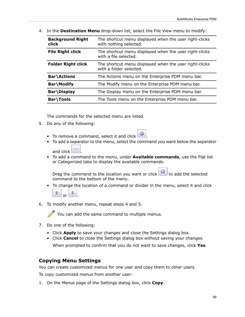
4. In the Destination Menu drop-down list, select the File View menu to modify:
The shortcut menu displayed when the user right-clickswith nothing selected.
Background Rightclick
The shortcut menu displayed when the user right-clickswith a file selected.
File Right click
The shortcut menu displayed when the user right-clickswith a folder selected.
Folder Right click
The Actions menu on the Enterprise PDM menu bar.Bar\Actions
The Modify menu on the Enterprise PDM menu bar.Bar\Modify
The Display menu on the Enterprise PDM menu bar.Bar\Display
The Tools menu on the Enterprise PDM menu bar.Bar\Tools
The commands for the selected menu are listed.
5. Do any of the following:
• To remove a command, select it and click .• To add a separator to the menu, select the command you want below the separator
and click .• To add a command to the menu, under Available commands, use the Flat listor Categorized tabs to display the available commands.
Drag the command to the location you want or click to add the selectedcommand to the bottom of the menu.
• To change the location of a command or divider in the menu, select it and click
or .
6. To modify another menu, repeat steps 4 and 5.
You can add the same command to multiple menus.
7. Do one of the following:
• Click Apply to save your changes and close the Settings dialog box.• Click Cancel to close the Settings dialog box without saving your changes.
When prompted to confirm that you do not want to save changes, click Yes.
Copying Menu SettingsYou can create customized menus for one user and copy them to other users.
To copy customized menus from another user:
1. On the Menus page of the Settings dialog box, click Copy.
99
SolidWorks Enterprise PDM

2. In the Copy Menu Settings dialog box, underMenus to copy, do one of the following:
• Select <Copy All Menus>.• Select a specific menu to copy.
3. Under Source user, select the user whose settings you want to copy.4. Click OK.5. Click Apply.
Returning to Default Menu SettingsYou can return a user's menus to their default settings. Resetting returns all menus totheir default settings.
1. On the Menus page of the Settings dialog box, click Reset.2. When prompted to confirm that you want to reset all menus, click OK.
Displaying Full User Names in the User InterfaceIf login names are cryptic, you can display users' full names in the user interface to makeit easier to identify who is using a file.
In Enterprise PDM, user names are displayed to indicate who has checked out or createdfiles, sent or received mail messages, or initiated actions performed on files.
If your company creates users with truncated user names, for example, by importingusers from Windows Active Directory, it may be difficult to identify individuals just bytheir login names.
You can modify your user settings in the Administration tool to specify that the full namesof users are displayed throughout the user interface.
Compare these examples of the Checked Out By column in File View in Windows Explorer:
Full names displayed:Login names displayed:
To display full user names:
1. In the left pane of the Administration tool, expand Users.2. Right-click your user name and click Settings.3. In the left pane of the Settings dialog box, click Explorer.4. Under Miscellaneous, select Show full user names.5. Click Apply.
100
SolidWorks Enterprise PDM
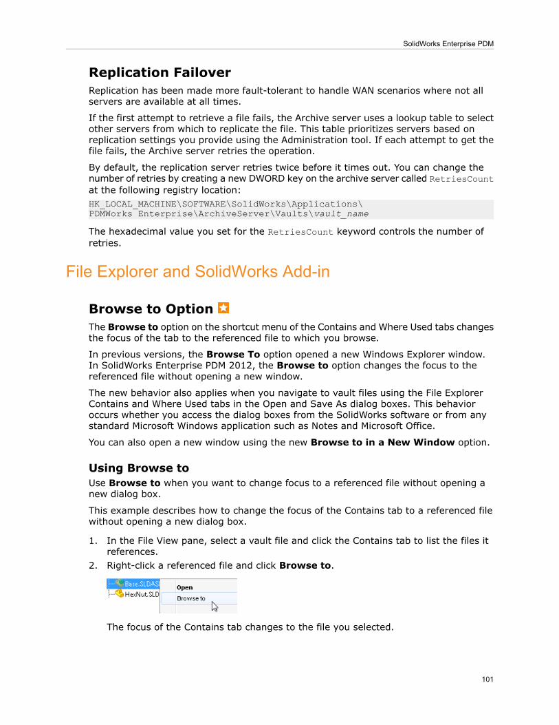
Replication FailoverReplication has been made more fault-tolerant to handle WAN scenarios where not allservers are available at all times.
If the first attempt to retrieve a file fails, the Archive server uses a lookup table to selectother servers from which to replicate the file. This table prioritizes servers based onreplication settings you provide using the Administration tool. If each attempt to get thefile fails, the Archive server retries the operation.
By default, the replication server retries twice before it times out. You can change thenumber of retries by creating a new DWORD key on the archive server called RetriesCountat the following registry location:HK_LOCAL_MACHINE\SOFTWARE\SolidWorks\Applications\PDMWorks Enterprise\ArchiveServer\Vaults\vault_name
The hexadecimal value you set for the RetriesCount keyword controls the number ofretries.
File Explorer and SolidWorks Add-in
Browse to OptionThe Browse to option on the shortcut menu of the Contains and Where Used tabs changesthe focus of the tab to the referenced file to which you browse.
In previous versions, the Browse To option opened a new Windows Explorer window.In SolidWorks Enterprise PDM 2012, the Browse to option changes the focus to thereferenced file without opening a new window.
The new behavior also applies when you navigate to vault files using the File ExplorerContains and Where Used tabs in the Open and Save As dialog boxes. This behavioroccurs whether you access the dialog boxes from the SolidWorks software or from anystandard Microsoft Windows application such as Notes and Microsoft Office.
You can also open a new window using the new Browse to in a New Window option.
Using Browse toUse Browse to when you want to change focus to a referenced file without opening anew dialog box.
This example describes how to change the focus of the Contains tab to a referenced filewithout opening a new dialog box.
1. In the File View pane, select a vault file and click the Contains tab to list the files itreferences.
2. Right-click a referenced file and click Browse to.
The focus of the Contains tab changes to the file you selected.
101
SolidWorks Enterprise PDM

Using Browse to in a New WindowUse Browse to in a New Window when you want to open a new window with the focuson a selected file.
1. In the File View pane, select a vault file and click the Where Used tab to list the filesthat reference it.
2. Right-click a file, and click Browse to in a New Window.A new window opens to the same folder and tab, but with the focus changed to thefile you selected.
The original window remains open.
Exporting Indented Bills of MaterialsYou can preserve the indented structure of an Enterprise PDM computed bill of materials(BOM) or a saved BOM when you export it to a Microsoft Excel spreadsheet. Whenprompted, choose to add a Level column to the output file. The added column containsa numerical representation of the BOM’s levels.
To preserve the indented structure of a BOM:
1. In Windows Explorer, select a vault assembly.
2. On the Bill of Materials tab, click BOM Display - Indented .
3. Click Open As CSV .4. When prompted to create a Level column in the CSV file, click Yes.
A Level column, with numerical values representing the BOM structure, appears asthe first column in the spreadsheet. You can use the column to sort the exported BOM.
Searching Within File-based Dialog BoxesThe embedded Enterprise PDM search lets you search for files and folders within WindowsExplorer and all standard file-based dialog boxes.
You can use this method to search from:
• SolidWorks file-based dialog boxes, such as Open, Save As, Insert, and Replace.• The Open and Save As dialog boxes of applications such as Microsoft Word and Excel,and Adobe Reader.
To perform an embedded search:
1. Do one of the following:
• Click Open Search (Enterprise PDM menu bar).
By default, the Complete Search card is used.
• If you have access to multiple file search cards, expand Open Search and select asearch card to use.
The search card appears in the top right pane.
102
SolidWorks Enterprise PDM
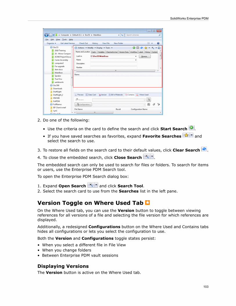
2. Do one of the following:
• Use the criteria on the card to define the search and click Start Search .
• If you have saved searches as favorites, expand Favorite Searches andselect the search to use.
3. To restore all fields on the search card to their default values, click Clear Search .
4. To close the embedded search, click Close Search .
The embedded search can only be used to search for files or folders. To search for itemsor users, use the Enterprise PDM Search tool.
To open the Enterprise PDM Search dialog box:
1. Expand Open Search and click Search Tool.2. Select the search card to use from the Searches list in the left pane.
Version Toggle on Where Used TabOn the Where Used tab, you can use the Version button to toggle between viewingreferences for all versions of a file and selecting the file version for which references aredisplayed.
Additionally, a redesigned Configurations button on the Where Used and Contains tabshides all configurations or lets you select the configuration to use.
Both the Version and Configurations toggle states persist:
• When you select a different file in File View• When you change folders• Between Enterprise PDM vault sessions
Displaying VersionsThe Version button is active on the Where Used tab.
103
SolidWorks Enterprise PDM

On the Contains tab, Version serves as a label for the version dropdown list. You canselect specific versions, but you cannot select <All Versions>.
With a vault file selected in File View, on the Where Used tab, do one of the following:
• To display files that reference all versions of the selected file, to the left of the top
drop-down list, click .
The Version: button is highlighted, and the drop-down list displays <All Versions>.
When all versions are displayed, you cannot select a specific configuration todisplay.
• To display files that reference a specific version of the selected file, click .
The Version button is no longer highlighted, and you can choose a specific versionfrom the drop-down list.
The highlighted Configuration button indicates that you can select a configurationfrom the drop-down list.
Displaying ConfigurationsOn both the Where Used and Contains tabs, the Configuration button lets you enableor disable the choice of configurations.
With a vault file selected in File View, use these methods to display configurations:
1. On the Contains tab:
• When the Configuration button is active, use the dropdown list to select theconfiguration for which to display referenced files.
• To deactivate the Configurations drop-down list, click Configuration.
The button becomes a label and the drop-down list indicates that you have chosennot to show configurations.
2. On the Where Used tab:a) If Version is active, click to deactivate it, and click Configuration to activate theability to choose configurations.The Configuration button is highlighted and the drop-down list becomes active.
b) Use the drop-down list to select the configuration to display.
104
SolidWorks Enterprise PDM
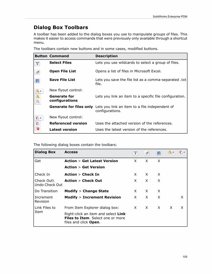
Dialog Box ToolbarsA toolbar has been added to the dialog boxes you use to manipulate groups of files. Thismakes it easier to access commands that were previously only available through a shortcutmenu.
The toolbars contain new buttons and in some cases, modified buttons.
DescriptionCommandButton
Lets you use wildcards to select a group of files.Select Files
Opens a list of files in Microsoft Excel.Open File List
Lets you save the file list as a comma-separated .txtfile.
Save File List
New flyout control:
Lets you link an item to a specific file configuration.Generate forconfigurations
Lets you link an item to a file independent ofconfigurations.
Generate for files only
New flyout control:
Uses the attached version of the references.Referenced version
Uses the latest version of the references.Latest version
The following dialog boxes contain the toolbars:
AccessDialog Box
XXXAction > Get Latest Version
Action > Get Version
Get
XXXAction > Check InCheck In
XXXAction > Check OutCheck Out\Undo Check Out
XXXModify > Change StateDo Transition
XXXXModify > Increment RevisionIncrementRevision
XXXXXFrom Item Explorer dialog box:
Right-click an item and select LinkFiles to Item. Select one or morefiles and click Open.
Link Files toItem
105
SolidWorks Enterprise PDM

Product SupportSolidWorks Enterprise PDM 2012 offers expanded support for CAD systems, Microsoft
®
Office, Internet Explorer®, and 64-bit processors.
The following support is available:
64-bit PlatformsMicrosoft ProductsCAD Tools
Enterprise PDM Web ServerMicrosoft Office 2010SolidWorks 2012
AutoCADInternet Explorer 9AutoCAD®2012
Solid EdgeAutodesk Inventor®2012
Solid Edge®ST3
System PerformanceSystem performance has been improved for users working with large data sets and usersworking remotely with Copy Tree and template-created documents.
• Improved system response time with large data sets
Users will now see significantly quicker system response when working with large datasets.
In previous versions of Enterprise PDM, long delays or system stoppages could occurwhen users worked with large data sets with many parent child relationships. Affectedfunctions included viewing the information on the Contains tab in Windows Explorer orin a CAD add-in when the Archive refresh rate is set at a low value, for example, fiveseconds.
• Creating new documents from remote replicated sites with high latency connectionsto the SQL Server
It now takes less time for users in remote offices to create new documents usingtemplates and the Copy Tree tool.
Combining the queries that save card variables has made the creation of documentsfrom templates as much as three times faster.
Improved query methods have optimized WAN traffic for the Copy Tree operation,making the new response time up to 10 times faster.
Web Client Access ExtendedThe SolidWorks Enterprise PDM Editor license now includes access to the Enterprise PDMWeb Client. This provides greater flexibility for users that are away from the office butstill need to access the system, and for external users, such as vendors or customers,that need occasional access.
In addition to providing access to CAD applications, you can use Editor licenses to accessthe Web client to search the vault and perform basic functions to enable remote workprocesses.
Licenses in the license pool are used in this order:
• Contributor licenses
106
SolidWorks Enterprise PDM

• Editor licenses• Processor license
107
SolidWorks Enterprise PDM

12Flow Simulation
Available as a separately purchased product that can be used with SolidWorks Standard,SolidWorks Professional, or SolidWorks Premium. Some Flow Simulation features are onlyavailable with the HVAC module add-on.
This chapter includes the following topics:
• Physical Models and Technology• Pre-Processor• Post-Processor
Physical Models and Technology
Advanced Geometry ResolutionEnhanced meshing technology improves the CAD geometry representation by thecomputational mesh. As a result, the accuracy of calculation is improved with fewernumber of cells.
In previous releases, there were partial cells that simplified the geometry by cutting thesharp corners residing in the cell. The new technology uses additional information fromthe CAD (e.g. edges) to construct the non-simplified geometry, wherever possible.
DO Radiation ModelThe DO radiation model is improved to give better accuracy in cases where geometricaloptics (e.g. focusing on lens, shadowing) is essential for the simulation.
Three discretisation level parameters have been added to the DO model:
• Level 5 (2nd order)• Level 6 (2nd order)• Level 7 (2nd order)
108
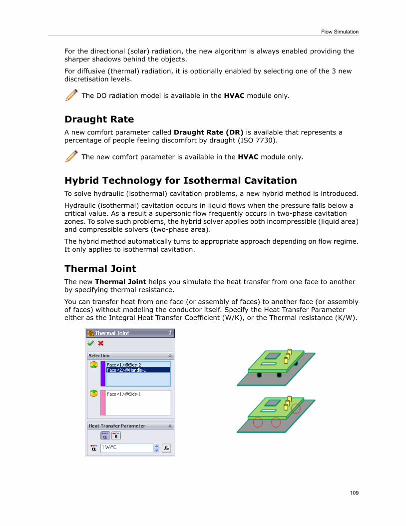
For the directional (solar) radiation, the new algorithm is always enabled providing thesharper shadows behind the objects.
For diffusive (thermal) radiation, it is optionally enabled by selecting one of the 3 newdiscretisation levels.
The DO radiation model is available in the HVAC module only.
Draught RateA new comfort parameter called Draught Rate (DR) is available that represents apercentage of people feeling discomfort by draught (ISO 7730).
The new comfort parameter is available in the HVAC module only.
Hybrid Technology for Isothermal CavitationTo solve hydraulic (isothermal) cavitation problems, a new hybrid method is introduced.
Hydraulic (isothermal) cavitation occurs in liquid flows when the pressure falls below acritical value. As a result a supersonic flow frequently occurs in two-phase cavitationzones. To solve such problems, the hybrid solver applies both incompressible (liquid area)and compressible solvers (two-phase area).
The hybrid method automatically turns to appropriate approach depending on flow regime.It only applies to isothermal cavitation.
Thermal JointThe new Thermal Joint helps you simulate the heat transfer from one face to anotherby specifying thermal resistance.
You can transfer heat from one face (or assembly of faces) to another face (or assemblyof faces) without modeling the conductor itself. Specify the Heat Transfer Parametereither as the Integral Heat Transfer Coefficient (W/K), or the Thermal resistance (K/W).
109
Flow Simulation

Tracer StudyWith a new tracer feature, you can quickly simulate concentration source, surfacecondensation, or evaporation of an admixture fluid (for example, water vapor or toxicgas) in the carrier fluid (for example, air). The presence of the admixture has negligibleinfluence on the carrier fluid flow.
Tracer is an admixture presented at low mass fraction in a carrier fluid with no influence(passive) on this carrier fluid. If concentration of a gas admixture is low you can considerit as a tracer (examples of tracers in air: water vapor, H2, CO, NO, NO2, Cl2, HCl, NH3,H2S, SO2).
The tracer feature is available in the HVAC module only.
Pre-Processor
Automatic Rebuild OptionsYou can now disable the automatic rebuilds.
When you define a Fluid Flow Simulation and modify the design, you can disable theautomatic rebuild in the option. This enhancement improves efficiency when you testdifferent design scenarios.
Callout at Invalid ContactYou can add callouts to invalid contact locations. The callouts identify improper contactsurfaces so you can fix them. The callouts also save you time by detecting the reasonsfor geometry issues.
Contact ResistanceThe Apply to solid/solid only option in the Contact Resistance dialog box allows youto specify contact resistance only at overlapping parts of solid surfaces in contact.
In the Contact Resistance PropertyManager, select Apply to solid/solid only.
110
Flow Simulation

Apply to solid/solid only: ONApply to solid/solid only: OFF
Post-Processor
Color BarSeveral usability improvements are implemented for the Color Bar.
• You can dynamically adjust the palette size, position, and number of levels of the ColorBar.
• A new option Auto scale in the Font dialog box adjust automatically the font size fortext in the Color Bar.
• You can define the default settings and appearance of the Color Bar under GeneralOptions.
• The Color Bar dialog box now contains a range of new palettes optimized forvisualization of the temperature distribution.
111
Flow Simulation

Context AnimationYou can save the animation displayed with the Context Animation tool.
Crop Region for Flow TrajectoriesYou can define a 3D box that crops the flow trajectories area. Use this option for largemodels to focus on the region of interest.
Exporting ResultsYou can simultaneously export multiple surface parameters to Microsoft Excel.
High-quality HighlightA high-quality highlight is available for indicating the selected plots or trajectories. Usethis option to distinguish contours of different parameters in one plot.
Parameter ListThe Parameter List dialog box has an improved interface that allows you to selectparameters more easily while viewing results. You can sort them by name, group or unit.
112
Flow Simulation

Reports
• You can use custom templates to generate reports when you analyze the results in theBatch-Results-Processing mode.
• You can generate analysis reports in HTML file format in addition to Microsoft Word fileformat.
113
Flow Simulation

13Import/Export
This chapter includes the following topics:
• Exporting Multisheet Drawings to the DXF or DWG Paper Space• Importing Creo Elements/Pro (Pro/Engineer) Files• Importing .IFC Files• Importing Unigraphics Files• STEP and Parasolid Assembly File Import
Exporting Multisheet Drawings to the DXF or DWG PaperSpace
You can export all sheets of a multisheet drawing to the file layout (paper) space andsave the document as a single .dxf or .dwg file.
From a multisheet drawing:
1. Click File > Save As.
2. In the dialog box, for Save as type, select DXF or DWG.3. Click Options.4. In the Export Options dialog box, for Multiple sheet drawing, select Export all
drawing sheets to paper space.
5. Set other options and click OK.6. In the Save As dialog box, type the filename and click Save.7. If the SolidWorks to DXF/DWG Mapping dialog box appears, specify mapping options
and click OK.
114

Importing Creo Elements/Pro (Pro/Engineer) FilesYou can import Pro/ENGINEER files up to version Creo Elements/Pro 5.0 (formerlyPro/ENGINEER Wildfire 5).
1. Click File > Open.
2. For Files of Type, select ProE Part or ProE Assembly.3. Select the file and click Open.
Importing .IFC FilesYou can import .ifc files into the SolidWorks software to include information from modelsoriginally created with structural software applications.
When you import .ifc files into SolidWorks, the file geometry is imported but theresulting SolidWorks model has essentially no features.
1. Click File > Open.
2. For Files of Type, select IFC 2x3.3. To set general options, click Options, set the options, and click OK.4. Select the file and click Open.
Importing Unigraphics FilesYou can import Unigraphics files up to version 7.5.
1. Click File > Open.
2. For Files of Type, select Unigraphics.3. To set general options, click Options, set the options, and click OK.4. Select the file and click Open.
115
Import/Export

STEP and Parasolid Assembly File ImportSTEP and Parasolid assembly file import performance has been improved. In addition,the SolidWorks software does not automatically save the resulting the SolidWorks file toyour disk.
116
Import/Export

14Motion Studies
Available in SolidWorks Premium.
This chapter includes the following topics:
• Motion Optimization• Including Motion Results in Sensors
Motion OptimizationYou can create a SolidWorks Simulation design study to optimize motion studies features.
• From the Parameters dialog box you can create and link variables to features fromMotion Analysis type studies.
• In a design study, you can specify constraints and goals that are linked to motion studyresults through sensors. You can perform an optimization or evaluate specific designscenarios.
• For each design iteration, you can view the motion animation within the design study.For any iteration of the design study, you can view detailed motion results in the motionstudy.
Including Motion Results in SensorsYou can define motion data sensors from motion results.
You can use motion data sensors to track a motion study result value. With aSolidWorks Simulation Professional license, you can use motion data sensors tooptimize motion parameters in a SolidWorks Simulation design study.
117

To create a motion data sensor to track a motion study result:
• From a Motion Analysis type study, do one of the following:
• Define the sensor by creating a new result first:
1. Click Results and Plots (MotionManager toolbar).2. Specify the result details.3. Select Create new motion data sensor.
4. Specify the other sensor properties and click .
• Define a new sensor to reference an existing result:
1. From the FeatureManager design tree, right-click Sensors and click AddSensor.
2. For Sensor Type , select Motion Data.
3. For Motion Study , select a motion study.
4. For Motion Study Result , select a result defined in the selected motionstudy.
5. Specify the other sensor properties and click .
118
Motion Studies
16Parts and Features
This chapter includes the following topics:
• Feature Freeze• Exploded Views of Multibody Parts• Hole Wizard - Placement of Holes• Part Reviewer• Templates for Split Parts• Reference Planes
Feature FreezeYou can freeze features to exclude them from rebuilds of the model.
The freeze bar controls the point at which a part’s FeatureManager design tree rebuilds.Features above the freeze bar are frozen – you cannot edit them, and they are excludedfrom rebuilds of the model.
Freezing a portion of a model can be useful if you work with complex models with manyfeatures. Freezing the features helps to:
• Reduce rebuild time• Prevent unintentional changes to the model
Feature Freeze prevents the geometry of frozen features from being rebuilt. However,you might still experience long rebuild times due to other processes that are notaddressed by Feature Freeze. Examples of potentially time-consuming processes notaddressed by Feature Freeze:
• Updating display appearances, especially on very large patterns• Updating complex DimXpert dimension and tolerance schemes• Updating the graphics (tessellation data) of very large, complex parts
Enabling Feature FreezeYou turn on Freeze in System Options.
1. Open install_dir\samples\whatsnew\Parts\shoe-4.sldprt.
119
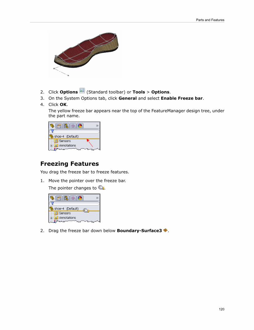
2. Click Options (Standard toolbar) or Tools > Options.3. On the System Options tab, click General and select Enable Freeze bar.4. Click OK.
The yellow freeze bar appears near the top of the FeatureManager design tree, underthe part name.
Freezing FeaturesYou drag the freeze bar to freeze features.
1. Move the pointer over the freeze bar.
The pointer changes to .
2. Drag the freeze bar down below Boundary-Surface3 .
120
Parts and Features

When the freeze bar is at the top of the tree, you can also right-click a featureand click Freeze to freeze that feature and all features above it in theFeatureManager design tree.
Features above the freeze bar are frozen – you cannot edit them, and they areexcluded from rebuilds of the model. Frozen features are indicated by an icon andgray text.
Exploded Views of Multibody PartsYou can create exploded views of multibody parts.
121
Parts and Features
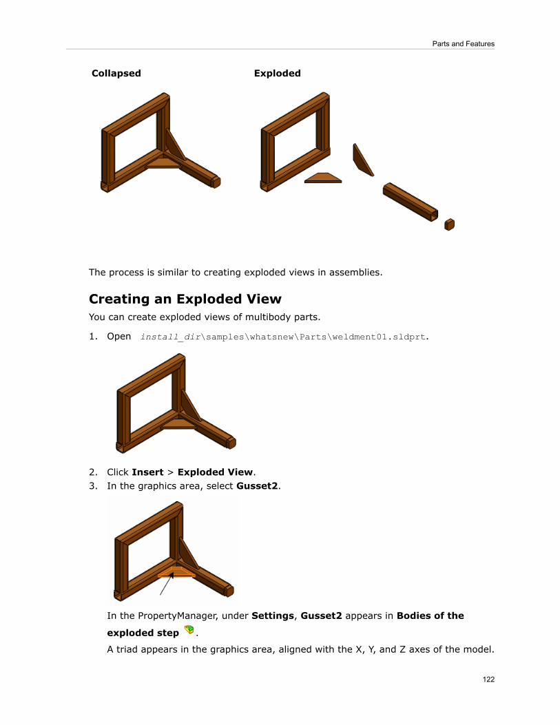
ExplodedCollapsed
The process is similar to creating exploded views in assemblies.
Creating an Exploded ViewYou can create exploded views of multibody parts.
1. Open install_dir\samples\whatsnew\Parts\weldment01.sldprt.
2. Click Insert > Exploded View.3. In the graphics area, select Gusset2.
In the PropertyManager, under Settings, Gusset2 appears in Bodies of the
exploded step .
A triad appears in the graphics area, aligned with the X, Y, and Z axes of the model.
122
Parts and Features

Next, change the alignment of the triad.
4. Right-click the center sphere of the triad and click Align to.5. Select the narrow face of the gusset.
The blue handle aligns normal to the selected face.
123
Parts and Features

6. Drag the blue handle to move the gusset forward.
7. Drop the gusset approximately as shown.
Auto-spacing BodiesYou can evenly space exploded groups of bodies.
1. In the graphics area, select the other gusset, the right-most structural member, andthe end cap.
2. In the PropertyManager, under Options, select Auto-space Solid Bodies afterdrag.
124
Parts and Features
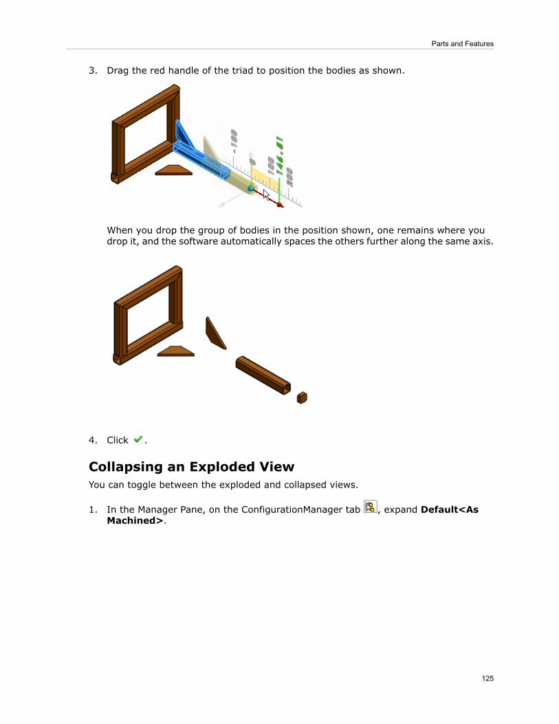
3. Drag the red handle of the triad to position the bodies as shown.
When you drop the group of bodies in the position shown, one remains where youdrop it, and the software automatically spaces the others further along the same axis.
4. Click .
Collapsing an Exploded ViewYou can toggle between the exploded and collapsed views.
1. In the Manager Pane, on the ConfigurationManager tab , expand Default<AsMachined>.
125
Parts and Features

2. Double-click ExplView, or right-click it and click Collapse.
3. To return to the exploded view, double-click ExplView again, or right-click it andclick Explode.
Animation of Explode and Collapse is not supported in multibody parts.
Hole Wizard - Placement of HolesYou can precisely define the position of the first point in a Hole Wizard sketch. Previously,the first point was placed wherever you clicked when selecting the face where you wantedto drill the hole.
When you activate the Positions tab, the first sketch point and a shaded preview of thehole follow the pointer until you click to place the hole. As you move the pointer aboutthe screen, you can take advantage of sketch snaps and inference lines to place the pointprecisely.
Part ReviewerYou can use Part Reviewer to review how parts are created feature-by-feature. PartReviewer can help you learn best practices for creating various types of parts.
Part Reviewer sample parts are located in the SolidWorks Forum. These sample partscontain comments about their features to teach you how they were created and why theywere used. You can also create your own parts and add your own comments.
126
Parts and Features
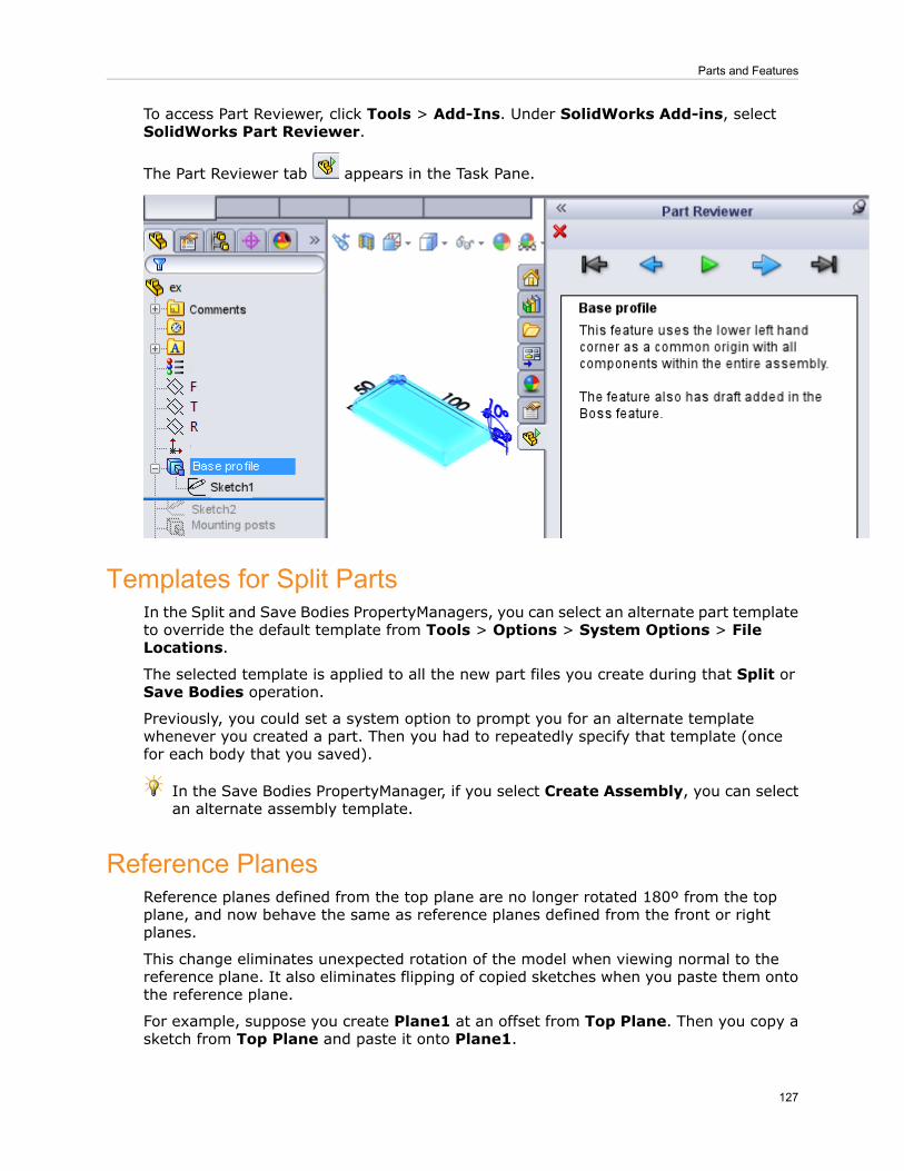
To access Part Reviewer, click Tools > Add-Ins. Under SolidWorks Add-ins, selectSolidWorks Part Reviewer.
The Part Reviewer tab appears in the Task Pane.
Templates for Split PartsIn the Split and Save Bodies PropertyManagers, you can select an alternate part templateto override the default template from Tools > Options > System Options > FileLocations.
The selected template is applied to all the new part files you create during that Split orSave Bodies operation.
Previously, you could set a system option to prompt you for an alternate templatewhenever you created a part. Then you had to repeatedly specify that template (oncefor each body that you saved).
In the Save Bodies PropertyManager, if you select Create Assembly, you can selectan alternate assembly template.
Reference PlanesReference planes defined from the top plane are no longer rotated 180º from the topplane, and now behave the same as reference planes defined from the front or rightplanes.
This change eliminates unexpected rotation of the model when viewing normal to thereference plane. It also eliminates flipping of copied sketches when you paste them ontothe reference plane.
For example, suppose you create Plane1 at an offset from Top Plane. Then you copy asketch from Top Plane and paste it onto Plane1.
127
Parts and Features

Previously, the copy of the sketch flipped180º.
In SolidWorks 2012, the copy of thesketch is oriented as expected.
128
Parts and Features
17Routing
Available in SolidWorks Premium.
Enhancements include the ability to create spools, add splices to electrical routes, createcustom routing templates, create BOMs with only routing components, and define dimensionsin routing models to the end face of flanges.
This chapter includes the following topics:
• Spools• Splices• Custom Route Property Templates• Bills of Materials Options• Dimensioning from Flanges
SpoolsRouting provides full support for spools.
You can create spools from existing pipe and tubing routes. Spools are sections of pipesor tubes and fittings that are manufactured separately and then connected during a finalassembly or construction process. You can identify the spools uniquely by name, color,and line style, associate adjacent components with spools, create drawings of spools,import route specifications from P&ID files, generate BOMs, and export spool data to thePCF file format for ISOGEN applications.
Defining SpoolsThe command is available from the Piping and Tubing menus. This topic describes thesteps from the Piping menu.
To define spools in a routing assembly:
1. Click Routing > Piping > Define Spools.You can also right-click the Route feature in the FeatureManager design tree andclick Define Spools.The Spools PropertyManager lists the name, color and line styles for the spool andits components.
129

2. In the assembly, select the sketch entities that make up a spool.Note: All segments and components in a spool must be contiguous. Gaps are notallowed in a spool. Also, you can only define one spool at a time.
3. For adjoining components, click the PropertyManager, and in the assembly, selectcomponents that are external to the spool. These components are typically tees andelbows that will be connected to the spool in the manufacturing process.
4. Add or remove components by dragging and dropping the entities betweenComponents and Adjoining Components in the PropertyManager.
5. Click .Spools are arranged in folders in the FeatureManager design tree of the route. Adisplay state is also generated for each spool.
The creation of spool drawings, BOMs, import of P&ID data, and export of spool data toPCF is integrated with the piping and tubing functionality. You can select options for spoolsin each of the related PropertyManagers for these functions. For more information, seeSolidWorks Help: Spools.
SplicesYou can add splices to electrical routes.
Splices are typically modeled as cylinders containing a single connection point. You canadd splices by splitting routes, by dragging and dropping splice components onto routes,and by adding splices from From-To lists. You can also create connector tables with splices,and add splices to BOMs.
Adding a SpliceThis topic describes how to add a splice after splitting the route.
1. Open a routing assembly in Edit Route mode.2. Right-click the sketch entity at the location where you want a split in the route and
click Routing > Electrical > Split Route.A split point is added where the sketch entities separate.
130
Routing

3. Select the split point and click Routing > Electrical > Add a Splice.4. From the Design Library, drag a splice component onto the split point.
The splice supports various wire sizes. Select the configuration of the splice componentto use based on the wire size.
Add the command for Add a Splice to the Electrical toolbar for easieraccess.
5. In the Add Splice PropertyManager, enter a name for the splice, and select theoptions to add a connector table and a BOM, if desired.
6. Click .
The splice is added to the FeatureManager design tree.
For more information, see SolidWorks Help: Splices.
Custom Route Property TemplatesYou can create route property templates that predefine parameters and defaults for aroute. In a template you can specify details such as standard pipes and elbows and pipesize ranges. You can set parameters for route properties like standard lengths for pipes,whether to select weld gaps, and whether to insert standard couplings. You can addcustom elbows. You can specify whether to always use elbows, always form bends, orprompt to select an elbow or bend along with the bend radii.
You can use the template to create an entire route or a single route segment.
When creating a route, the software automatically filters pipes and elbows based on thesize and schedule defined in the template.
To create a route property template:
1. Click Routing Tools > Routing Library Manager. Then click the Route Propertiestab.
2. In Select Properties Template, you can add a new template, copy an existing templateor delete a template.
131
Routing

3. In Pipe Settings, you can select pipes from the Piping and Tubing database. You canset defaults for selected pipe including the schedule, a standard weld gap, pipe length,and whether to insert a standard coupling. You can also pick elbows from the databaseor create custom elbows.
When you build a new routing assembly, the entries from your default template appear.For example, it applies the default elbow at appropriate locations. If you have configuredadditional templates, you can select those from a list. You can also override a templateand edit the entries.
For more information, see SolidWorks Help: Routing Library Manager.
Bills of Materials OptionsYou can manage routing components in BOMs. You can create BOMs that show onlyrouting components. You can list all pipes and tubes individually in BOMs, or you can listall pipes and tubes of the same size as a single line item with a sum of the total pipe ortube length.
You can generate a BOM from the drawing view of an assembly. If an assembly includesany routing components, the Bill of Materials PropertyManager includes an extra sectionfor Routing Component Grouping.
These options are available without the Routing add-in.
Selecting Show only routing components in BOM generates a BOM with only pipe,tube, wire and other routing components. No other types of components are included.
Selecting Group pipes or tubes with the same diameter and schedule lists all thepipes and tubes of the same size as one item, with the sum of the lengths and schedulesfor those components. For example, instead of showing that an assembly contains 6 unitsof a certain pipe that are 10 inches long and 8 more pipes that are 12 inches long, theBOM displays one item for the size pipe with a total length of 156 inches.
Selecting the options in different combinations produces different results. For example:
• Selecting both options produces a BOM that lists only routing components, and combinespipes and tubes of each size.
• Selecting the first option but not the second produces a BOM that lists only routingcomponents, but lists all pipes, tubes and wires individually.
• Selecting the second option but not the first, produces a BOM that includes all thenon-routing components in the assembly, but combines the pipe and tubes of eachdiameter and schedule.
Dimensioning from FlangesIn route models, you can define driving dimensions that start with the end face of aflange. Adding a dimension between a flange face and a route does not cause the sketchto be over defined.
In previous releases, you could not add dimensions between the end face of a flange anda route.
132
Routing

133
Routing

18Sheet Metal
This chapter includes the following topics:
• Cuts Across Bends• Edge Flanges• Flat Patterns• Forming Tools• Swept Flanges
Cuts Across BendsYou can unfold a part that has cuts across bends when the cuts do not go through theentire part. This is helpful when making flat patterns for manufacturing.
Unfolded partPart with a cut across a bend. The cut doesnot go through the entire part.
Edge FlangesNew options in the Edge-Flange PropertyManager let you create edge flanges based ontangent distance in flange length and create flange positions that are tangent to theadjacent side face attached to the selected edge. Additionally, when you create a flangelength as Up To Vertex, you can create the flange parallel to the base flange as well asnormal to the flange plane.
Tangent Bend Flange Length
You can set an edge flange length to Tangent Bend. This option is valid for bends thatare greater than 90º and lets you use the tangent length of a flange as the basis for thelength calculation. Tangent Bend lets you type in the tangent length without usingadditional calculations.
134

In the Edge-Flange PropertyManager, under Flange Length, click Tangent Bend .
Up to Vertex Flange Length
If you set an edge flange length to Up To Vertex, you can create it normal to the flangeplane or parallel to the base flange.
In the Edge-Flange PropertyManager, under Flange Length, set Length End Conditionto Up To Vertex, then select Normal to flange plane or Parallel to base flange.
Example of edge flange lengths using the options for Up To Vertex:
Parallel to base flange: The red vertexpasses through a plane that is parallel tothe face of the base flange. (A sketch line
is displayed for clarity.)
Normal to flange plane (existingfunctionality): The red vertex is coincidentto the end face of the edge flange. (A sketch
line is displayed for clarity.)
Tangent to Bend Flange Position
You can set an edge flange position to Tangent to Bend. This option is valid for all flangelength options and for bends that are greater than 90º.
135
Sheet Metal
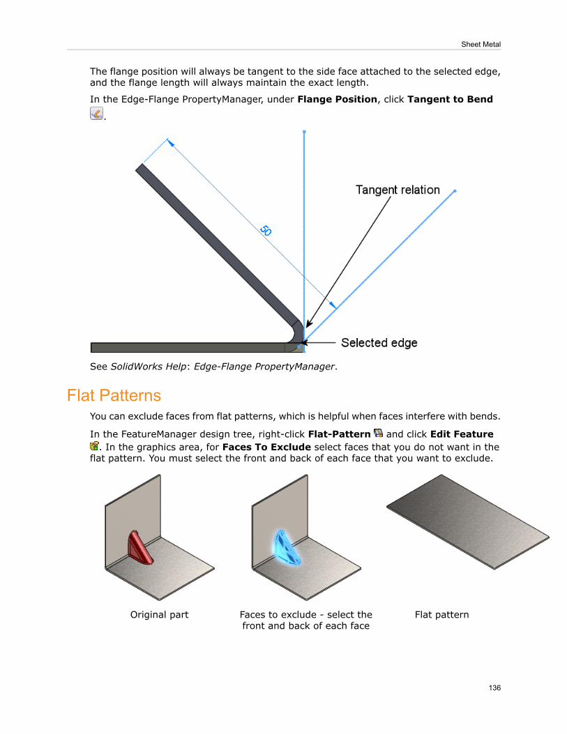
The flange position will always be tangent to the side face attached to the selected edge,and the flange length will always maintain the exact length.
In the Edge-Flange PropertyManager, under Flange Position, click Tangent to Bend
.
See SolidWorks Help: Edge-Flange PropertyManager.
Flat PatternsYou can exclude faces from flat patterns, which is helpful when faces interfere with bends.
In the FeatureManager design tree, right-click Flat-Pattern and click Edit Feature. In the graphics area, for Faces To Exclude select faces that you do not want in the
flat pattern. You must select the front and back of each face that you want to exclude.
Flat patternFaces to exclude - select thefront and back of each face
Original part
136
Sheet Metal

Forming ToolsForming tools include several enhancements that improve the workflow.
You can:
• Select configurations of the forming tools or target parts.• Change the placement face where you locate the forming tools.• Create links to forming tools, so that if you change the original forming tool, the changespropagate to target parts where you use the forming tool.
• Replace existing forming tools with different forming tools.• Set the appearance of placement sketches in flat patterns.• Assign punch IDs for use in punch tables.
Inserting Forming ToolsWhen you insert forming tools, the Form Tool PropertyManager provides an easier interfacefor tasks such as selecting the placement face, flipping the tool, and choosingconfigurations.
1. Open install_dir\samples\whatsnew\sheetmetal\cover.sldprt.A sheet metal part opens.
2. In the Task Pane, click the Design Library tab.3. Navigate to forming tools/louvers.4. Drag sample_louver to the face shown.
137
Sheet Metal
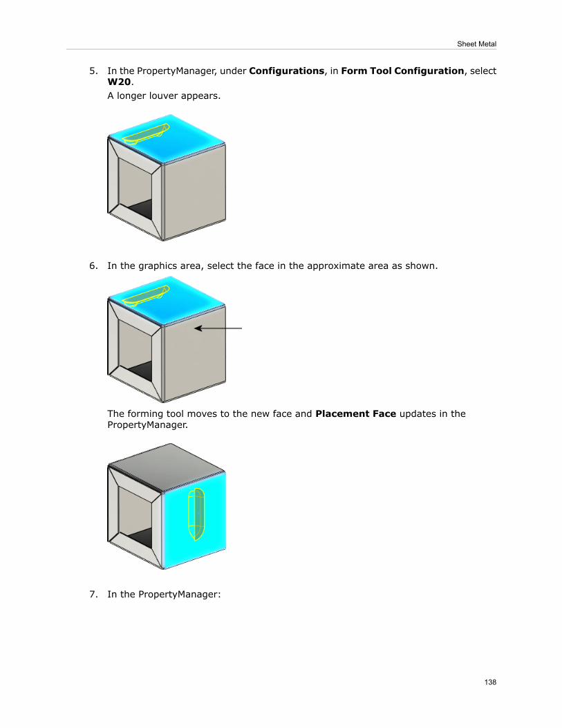
5. In the PropertyManager, under Configurations, in Form Tool Configuration, selectW20.A longer louver appears.
6. In the graphics area, select the face in the approximate area as shown.
The forming tool moves to the new face and Placement Face updates in thePropertyManager.
7. In the PropertyManager:
138
Sheet Metal

Under Rotation Angle, set the value to 270, then click Flip Tool.a)
b) Click the Position tab.
8. In the graphics area, select the areas shown to insert two more instances of theforming tool.
9. Click Smart Dimension (Sketch toolbar) or Tools > Dimensions > Smart, anddimension the points as shown.
139
Sheet Metal

10. Click twice.
11. Keep this part open for the next procedure.
See SolidWorks Help: Applying Forming Tools to Sheet Metal Parts.
Replacing Forming ToolsAfter you insert a forming tool in a model, you can replace the forming tool with anotherone.
1. In cover.sldprt, in the FeatureManager design tree, right-clicksample_louver1(W20) and click Replace Form Tool.
2. In the dialog box, navigate to install_dir\Documents and Settings\AllUsers\Application Data\SolidWorks\SolidWorks 2012\design library\formingtools\embosses\extruded hole.sldprt and click Open.
3. In the PropertyManager, click .The louver is replaced with the hole.
4. Keep this part open for the next procedure.
See SolidWorks Help: Replace Form Tool PropertyManager.
140
Sheet Metal
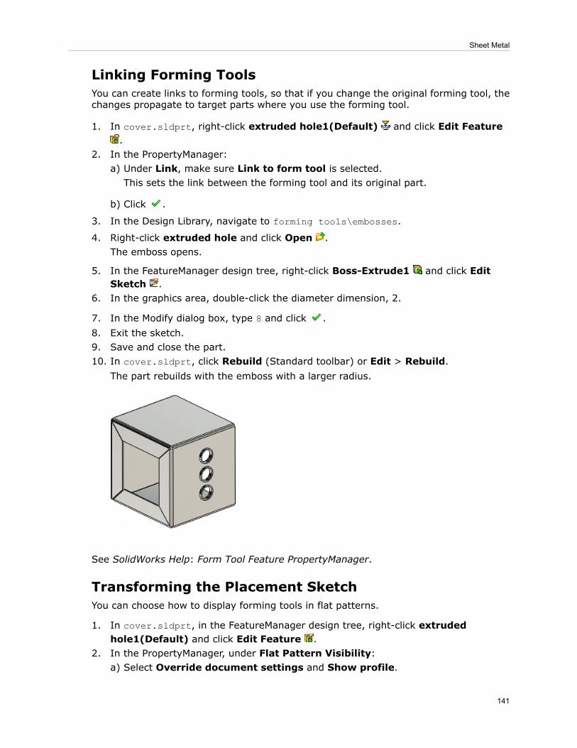
Linking Forming ToolsYou can create links to forming tools, so that if you change the original forming tool, thechanges propagate to target parts where you use the forming tool.
1. In cover.sldprt, right-click extruded hole1(Default) and click Edit Feature.
2. In the PropertyManager:a) Under Link, make sure Link to form tool is selected.This sets the link between the forming tool and its original part.
b) Click .
3. In the Design Library, navigate to forming tools\embosses.
4. Right-click extruded hole and click Open .The emboss opens.
5. In the FeatureManager design tree, right-click Boss-Extrude1 and click EditSketch .
6. In the graphics area, double-click the diameter dimension, 2.
7. In the Modify dialog box, type 8 and click .8. Exit the sketch.9. Save and close the part.10. In cover.sldprt, click Rebuild (Standard toolbar) or Edit > Rebuild.
The part rebuilds with the emboss with a larger radius.
See SolidWorks Help: Form Tool Feature PropertyManager.
Transforming the Placement SketchYou can choose how to display forming tools in flat patterns.
1. In cover.sldprt, in the FeatureManager design tree, right-click extrudedhole1(Default) and click Edit Feature .
2. In the PropertyManager, under Flat Pattern Visibility:a) Select Override document settings and Show profile.
141
Sheet Metal

b) Clear any other options.
c) Click .
3. In the FeatureManager design tree, right-click Flat-Pattern1 and click Unsuppress.The forming tool's profile (placement sketch) appears in the flattened part.
4. Right-click Flat-Pattern1 and click Suppress .5. Keep this part open for the next procedure.
See SolidWorks Help: Form Tool Feature PropertyManager.
Creating Punch IDsYou can add punch IDs to forming tools for easier identification in punch tables.
1. In the Design Library, right-click extruded hole and click Open .The emboss opens.
2. Click File > Properties.3. In the dialog box, on the Configuration Specific tab:
a) In Property Name, select PunchID.b) In Type, select Text.c) For Value / Text Expression, type P1.d) Click OK.
4. Save the part.
Inserting a Punch TablePunch tables are available with the flat pattern view of sheet metal parts and contain theform features and library features used in sheet metal bodies.
1. In cover.sldprt, clickMake Drawing from Part/Assembly (Standard toolbar)or File > Make Drawing from Part.
2. In the New SolidWorks Document dialog box, click Drawing , then click OK.3. In the Sheet Format/Size dialog box, click OK.4. In the View Palette, drag the Flat pattern view onto the sheet.
5. In the PropertyManager, click .
6. Click Punch Table (Table toolbar) or Insert > Tables > Punch Table.7. In the graphics area, click:
142
Sheet Metal
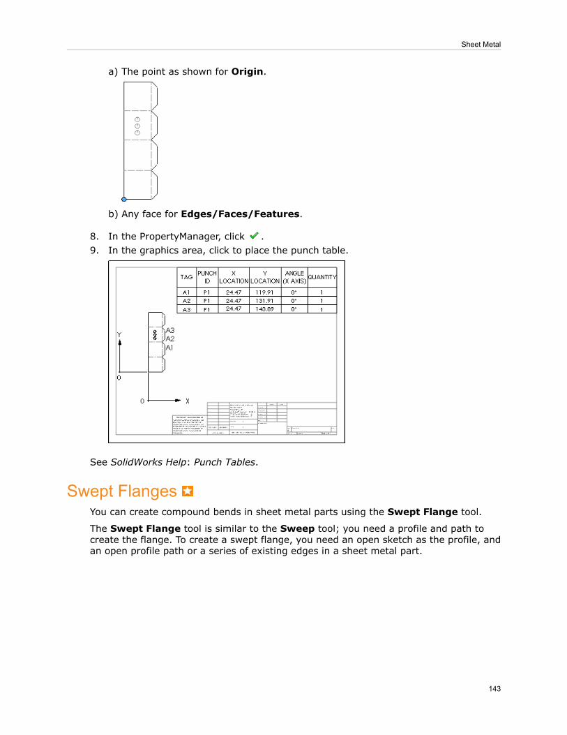
The point as shown for Origin.a)
b) Any face for Edges/Faces/Features.
8. In the PropertyManager, click .9. In the graphics area, click to place the punch table.
See SolidWorks Help: Punch Tables.
Swept FlangesYou can create compound bends in sheet metal parts using the Swept Flange tool.
The Swept Flange tool is similar to the Sweep tool; you need a profile and path tocreate the flange. To create a swept flange, you need an open sketch as the profile, andan open profile path or a series of existing edges in a sheet metal part.
143
Sheet Metal
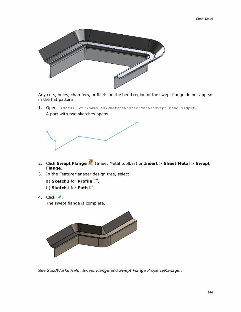
Any cuts, holes, chamfers, or fillets on the bend region of the swept flange do not appearin the flat pattern.
1. Open install_dir\samples\whatsnew\sheetmetal\swept_bend.sldprt.A part with two sketches opens.
2. Click Swept Flange (Sheet Metal toolbar) or Insert > Sheet Metal > SweptFlange.
3. In the FeatureManager design tree, select:
a) Sketch2 for Profile .
b) Sketch1 for Path .
4. Click .The swept flange is complete.
See SolidWorks Help: Swept Flange and Swept Flange PropertyManager.
144
Sheet Metal

19Simulation
• SolidWorks Simulation is available in SolidWorks Premium.• SolidWorks Simulation Professional and SolidWorks Simulation Premium are available asseparately purchased products that can be used with SolidWorks Standard, SolidWorksProfessional, or SolidWorks Premium.
This chapter includes the following topics:
• Beams• Connectors• Parameters Interface• Motion Optimization• Creating a Design Study with Motion Parameters• Optimization of a Catapult with Motion Features• Nonlinear Studies• Shells
BeamsEnhancements include availability of beams in linear dynamics studies, imprinting ofactual cross-sections for bonding connections, evaluation of torsional constants, and morerealistic rendering of beam profiles.
Beams in Linear Dynamic StudiesBeam elements are supported in Linear Dynamic studies, which include: Modal TimeHistory, Harmonic, Random Vibration, and Response Spectra analyses. Use beams tosimplify problems with weldments or structural members, improve simulation performance,and reduce the file size of results.
Performing Dynamic Analysis with Beam Models
To perform a linear dynamic analysis for models that include beams:
1. Create a Linear Dynamic study, and select one of the study options depending on theloading and response parameters you want to access after running the study.You can also copy an existing frequency study to a new dynamic study.
2. Set the frequency and dynamic properties of the study.3. Define material. You can apply only Linear Elastic Isotropicmaterial type to beams.4. Define restraints. Fixed Geometry, Immovable (No translation), and Use
Reference Geometry are available for beams.5. Define Loads. You can choose from the following options:
145

• Time-dependent force ortorque
Available for modal time history analysis studies.Select beam joints or the entire beam length to applyforce or torque values.
Available for harmonic and random vibration studies.Select beam joints or the entire beam length to applyforce or torque values.
Frequency-dependentforce or torque
• Uniform and selected baseexcitations For Random Vibration and Response Spectra
Analysis, you can apply base excitation only inthe global X, Y, Z directions.
• Available for modal time history analysis studies.Displacements, velocities, or accelerations at time = 0. You
Initial conditions
can apply initial conditions to beam joints or the entire beamlength.
6. Define damping.7. Define contact. You can select Bonded or Allow Penetration.8. Mesh the model and run the study.9. View the results:
• You can generate time history graphs at selected nodes. Right-click Results, andselect Define Response Graph.
• You can plot stresses (axial, bending, highest axial and bending, torsional, andshear), displacements, velocities and accelerations for a specified solution step,or extreme values across all solution steps. Right-click Results, and select fromthe plot options.
Beam BondingWhen beam joints are connected to a neighboring face of a solid or shell, the beam’sactual cross-section is meshed and imprinted on the solid or shell face, creating a moreaccurate bonding connection.
During meshing, elements are created in the imprinted beam section area. The end beamjoint is connected to all elements inside the imprinted section area forming a more realisticrepresentation of the joint.
146
Simulation

If the beam's cross-section is partially touching on a solid or shell face, only the touchingpart of the cross-sectional area gets imprinted.
Enhanced algorithms automatically bond beam joints to touching solids or shell faces.When you set the Global Contact to Bonded, the software automatically bonds: (a)beam end joints to touching faces, and (b) beams that act as stiffeners to planar or curvedsurfaces that have touching geometries, or are situated within reasonable clearance.
Torsional Constants for BeamsSolidWorks Simulation computes the torsional constant and shear factor entries for beamsections. The shear center line of all beams is shown, along with the neutral axis.
For torsional shear stress calculation, the program calculates the torsional constant, anddistance from the center of the section to the point of maximum torsional shear for allbeam cross-sections. For shear stress calculation, the program calculates the two shearfactors that account for the nonuniform shear stress distribution across the beam'scross-section.
To view the section properties of a beam, right-click the beam definition and select EditDefinition. The torsional constant, distance for maximum shear stress, and shear factorsare listed under Section Properties in the Apply/Edit Beam PropertyManager.
You can override the beam section properties calculated by the program withuser-defined values.
To view the shear center line of a beam, right-click Joint group and select Edit. UnderResults, select Display shear center. A red line shows the shear center of beams inthe graphics area.
147
Simulation

Beam ResultsBeam mesh and result plots can now be shown on actual beam geometry. eDrawingssupports the new plots.
In previous releases, mesh and result plots for beam studies were displayed on cylindersand not the actual beam geometry. You now have the option to display the results eitheron cylinders or on the beam geometry.
SolidWorks Simulation 2012Previous releases of SolidWorks Simulation
Displaying Mesh on Beam Geometry
To display the mesh on actual beam geometry as opposed to cylinders:
1. In a Simulation study, click Simulation > Options.2. On the Default Options tab, click Mesh.3. Select Render beam profile, and click OK.
148
Simulation

4. In the Simulation study tree, right-click Mesh and click Show Mesh.
Render beam profile clearedRender beam profile selected
Displaying Stress Plots on Beam Geometry
To display a stress plot on actual beam geometry:
1. In the Simulation study tree, right-click Results and click Define Stress Plot.2. In the Stress Plot PropertyManager, under Display, select Render beam profile.
3. Click .
In the Stress Plot PropertyManager, under Display, in Beam stress, HighestAxial and Bending is now replaced by Axial and bending, which shows thecombined uniform axial stresses and axial stresses resulting from bending. Theseplots now display the stress distribution throughout the beam, and no longerdisplay a single color. In previous releases, a single color represented themaximum value across the beam's cross-section.
In stress plots, nodal as well as element results are available for beams. As before,element plots display on cylindrical cross sections.
If the Render beam profile option is cleared in the Stress Plot PropertyManager, thesoftware assigns the highest stress value for the element and axial components. Forexample, you can select from Highest axial and bending, Highest Bending in localdirection 1, or Highest Bending in local direction 2.
149
Simulation

If the Render beam profile option is selected in the Stress Plot PropertyManager, bendingstresses vary across the cross-section, as well as along the axis of the beam. For example,you can select from Axial and bending, Bending in local direction 1, or Bending inlocal direction 2, which indicates that the values vary throughout the cross-section.
This option can be slow in studies with many beam elements. To improve performancein these instances, limit the rendering of the beam to the final results.
Displaying Displacement Plots on Beam Geometry
To display a displacement plot on actual beam geometry:
1. In the Simulation study tree, right-click Results and click Define DisplacementPlot.
2. In the Displacement Plot PropertyManager, under Advanced Options, select Renderbeam profile.
3. Click .
Render beam profile clearedRender beam profile selected
150
Simulation

Displaying Beam Results in eDrawingsYou can save beam results on actual beam geometry and display them in eDrawings asthey appear in SolidWorks Simulation. Previously, beam results displayed on cylinders ineDrawings.
To save beam results on actual beam geometry and display them in eDrawings:
1. Create the beam plots in SolidWorks Simulation.2. In the Simulation study tree, right-click Results and click Save All Plots as
eDrawings.3. In the Save As dialog box, enter a Save in location and File name. Click Save.4. Open the file in eDrawings.
ConnectorsEnhancements for connectors include improved accuracy for the edge weld connector,support of all connectors (except bolt and elastic support) for linear dynamic studies, andcreation of a bolt or pin connector on the same component.
• The calculation of the weld sizes for the edge weld connector is more accurate due tothe improvement of the bonding algorithm between shell edges and faces.
• All connectors, except the bolt connector and the elastic support, are supported inLinear Dynamic studies.
151
Simulation
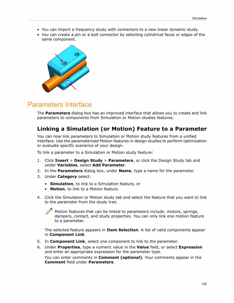
• You can import a frequency study with connectors to a new linear dynamic study.• You can create a pin or a bolt connector by selecting cylindrical faces or edges of thesame component.
Parameters InterfaceThe Parameters dialog box has an improved interface that allows you to create and linkparameters to components from Simulation or Motion studies features.
Linking a Simulation (or Motion) Feature to a ParameterYou can now link parameters to Simulation or Motion study features from a unifiedinterface. Use the parameterized Motion features in design studies to perform optimizationor evaluate specific scenarios of your design.
To link a parameter to a Simulation or Motion study feature:
1. Click Insert > Design Study > Parameters, or click the Design Study tab andunder Variables, select Add Parameter.
2. In the Parameters dialog box, under Name, type a name for the parameter.3. Under Category select:
• Simulation, to link to a Simulation feature, or• Motion, to link to a Motion feature.
4. Click the Simulation or Motion study tab and select the feature that you want to linkto the parameter from the study tree.
Motion features that can be linked to parameters include: motors, springs,dampers, contact, and study properties. You can only link one motion featureto a parameter.
The selected feature appears in Item Selection. A list of valid components appearin Component Link.
5. In Component Link, select one component to link to the parameter.6. Under Properties, type a numeric value in the Value field, or select Expression
and enter an appropriate expression for the parameter type.You can enter comments in Comment (optional). Your comments appear in theComment field under Parameters.
152
Simulation

7. Click Apply.An asterisk appears under Linked to show that the highlighted parameter is nowlinked.
8. You can continue adding new parameters or click OK to exit the dialog.
Motion OptimizationYou can create a SolidWorks Simulation design study to optimize motion studies features.
• From the Parameters dialog box you can create and link variables to features fromMotion Analysis type studies.
• In a design study, you can specify constraints and goals that are linked to motion studyresults through sensors. You can perform an optimization or evaluate specific designscenarios.
• For each design iteration, you can view the motion animation within the design study.For any iteration of the design study, you can view detailed motion results in the motionstudy.
Creating a Design Study with Motion ParametersWith a Design study, you can evaluate several design scenarios based on parameterizedfeatures from motion analysis-type studies, and also optimize your design based ondefined goals.
1. Create a motion analysis-type study that includes features to parameterize in a designstudy (i.e., springs, dampers, motors, contact, or force).
2. Click Insert > Design Study > Parameters to create Motion-type parameters, andlink them to the desired features of the motion analysis-type study.Parameters are added as variables in the Design study.
See also Linking a Simulation (or Motion) Feature to a Parameter on page 152.
3. Define sensors to add as Constraints or Goals in the Design study by doing on thefollowing:
153
Simulation
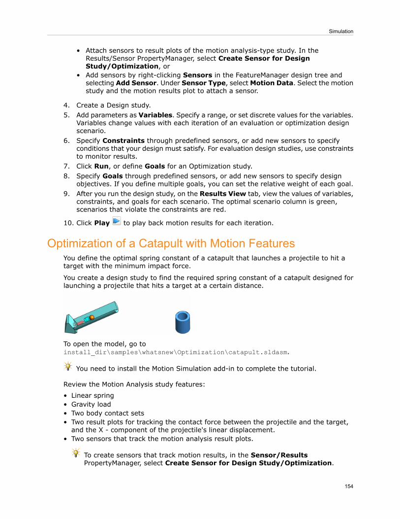
Attach sensors to result plots of the motion analysis-type study. In theResults/Sensor PropertyManager, select Create Sensor for DesignStudy/Optimization, or
•
• Add sensors by right-clicking Sensors in the FeatureManager design tree andselecting Add Sensor. Under Sensor Type, selectMotion Data. Select the motionstudy and the motion results plot to attach a sensor.
4. Create a Design study.5. Add parameters as Variables. Specify a range, or set discrete values for the variables.
Variables change values with each iteration of an evaluation or optimization designscenario.
6. Specify Constraints through predefined sensors, or add new sensors to specifyconditions that your design must satisfy. For evaluation design studies, use constraintsto monitor results.
7. Click Run, or define Goals for an Optimization study.8. Specify Goals through predefined sensors, or add new sensors to specify design
objectives. If you define multiple goals, you can set the relative weight of each goal.9. After you run the design study, on the Results View tab, view the values of variables,
constraints, and goals for each scenario. The optimal scenario column is green,scenarios that violate the constraints are red.
10. Click Play to play back motion results for each iteration.
Optimization of a Catapult with Motion FeaturesYou define the optimal spring constant of a catapult that launches a projectile to hit atarget with the minimum impact force.
You create a design study to find the required spring constant of a catapult designed forlaunching a projectile that hits a target at a certain distance.
To open the model, go toinstall_dir\samples\whatsnew\Optimization\catapult.sldasm.
You need to install the Motion Simulation add-in to complete the tutorial.
Review the Motion Analysis study features:
• Linear spring• Gravity load• Two body contact sets• Two result plots for tracking the contact force between the projectile and the target,and the X - component of the projectile's linear displacement.
• Two sensors that track the motion analysis result plots.
To create sensors that track motion results, in the Sensor/ResultsPropertyManager, select Create Sensor for Design Study/Optimization.
154
Simulation

Defining the Design Study VariableYou define the spring constant as a parameter, and you add it as a variable in the designstudy.
1. Create a new Design Study.2. On the Variable View tab, expand Variables, and select Add Parameter. In the
Parameters dialog box:a) Under Name, type a name for the parameter, i.e. Spring_Constant.b) Under Category, select Motion.c) In the Motion study tree, double-click LinearSpring2.The spring feature is highlighted in Item Selection, and all available componentsare listed in Component Link.
d) Select the component Spring Constant (Spring) to link to the parameter.e) For Value, type 17500.f) Click Apply and OK.An asterisk under Linked shows that the selected component is now linked to theparameter.
3. Add the parameter under Variables.4. Select Range with step. For Min, type 17400 (N/m), for Max, type 17600 (N/m),
for Step, type 25 (N/m).
Defining Constraint and GoalYou define the sensor that tracks the X-component of the projectile's trajectory as aconstraint . As a goal, you want to minimize the impact force of the projectile when ithits the target.
1. On the Variable View tab, in Constraints, select the displacement sensor. Forcondition, select Is between. For Min, select -0.1 and for Max, 0.1.This condition enforces the limits for the X-component of the projectile's displacement,so that it can hit the target.
2. In Goals, select the force sensor. For condition, select Minimize.As a goal, you want to minimize the contact force of the projectile when it hits thetarget. If you do not define any goals, you can run the design study as an evaluationdesign study. There is a total of nine active design scenarios
You are now ready to run the optimization study.
Running the Optimization
1. Select Optimization and click Run.The program invokes the Motion Analysis study at each iteration, and reports thevalues for each iteration.
2. On the Results View tab, select Scenario1 and click Play from Start . Themotion animation appears in the graphics area. Scenarios that do not satisfy theconstraints are highlighted in red. In this scenario, the projectile misses the target.
155
Simulation

3. Select Optimal (4), which is the optimal scenario highlighted in green, and click
Play from Start .For the projectile to hit the target, the required spring constant of the catapult is17475 N/m.
You can switch to the Motion Analysis study tab, to view motion result plotscorresponding to the active design scenario.
Nonlinear StudiesImprovements in the areas of contact convergence and I/O data handling enhance theoverall quality of nonlinear analysis.
• Performance improvements ranging from 15% to 30%, for most studies, in reductionof overall solution time. Some studies have shown over 50% performance improvement.
• The surface-based option for bonding is extended to nonlinear studies.
To apply surface-based bonding, in the Nonlinear - Static dialog box, under Incompatiblebonding options, select More accurate (slower).
• The convergence and solution accuracy of the surface-based contact algorithm areimproved. As a result, nonlinear problems with the following features are improved:
1. Surface-based bonding contact and connectors2. No penetration contact with friction3. Combination of shrink-fit and no penetration contact (differentiate the two types ofcontact in the database)
ShellsEnhancements for shells include:
• Automatic detection of contact pairs between touching shell edges connected to facesis expanded to include combinations with non-planar faces and circular edges.
• Improved accuracy of the bonding algorithm between shell edges and solid faces forstatic, frequency, buckling, and nonlinear studies.
• Transfer of temperature and pressure data from SolidWorks Flow Simulation.
Auto-bonding Shell Edges to FacesThe automatic detection of touching shell edges connected to solid or shell faces isimproved to include more combinations with non-planar faces and circular shell edges.
The software automatically bonds the detected contact pairs between shell edges andfaces when you define bonded contact either globally or locally.
The Contact Sets PropertyManager has a new option: Find shell edge - solid/shellface pairs.
156
Simulation
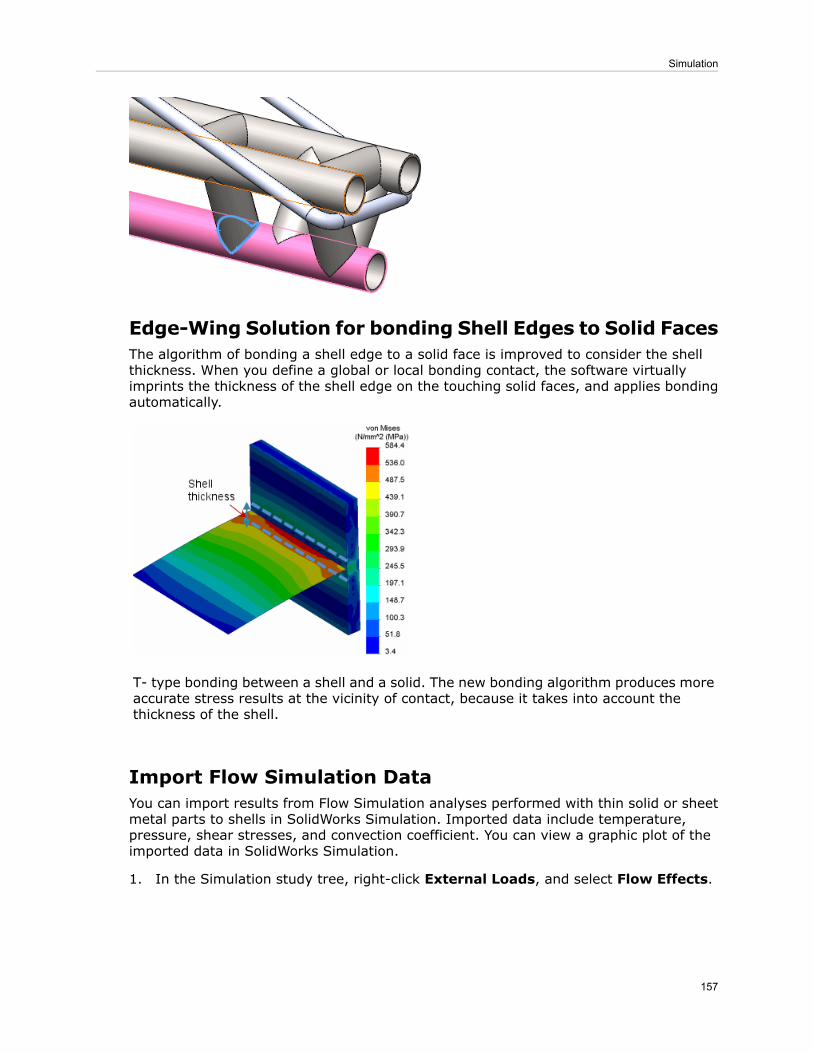
Edge-Wing Solution for bonding Shell Edges to Solid FacesThe algorithm of bonding a shell edge to a solid face is improved to consider the shellthickness. When you define a global or local bonding contact, the software virtuallyimprints the thickness of the shell edge on the touching solid faces, and applies bondingautomatically.
T- type bonding between a shell and a solid. The new bonding algorithm produces moreaccurate stress results at the vicinity of contact, because it takes into account thethickness of the shell.
Import Flow Simulation DataYou can import results from Flow Simulation analyses performed with thin solid or sheetmetal parts to shells in SolidWorks Simulation. Imported data include temperature,pressure, shear stresses, and convection coefficient. You can view a graphic plot of theimported data in SolidWorks Simulation.
1. In the Simulation study tree, right-click External Loads, and select Flow Effects.
157
Simulation
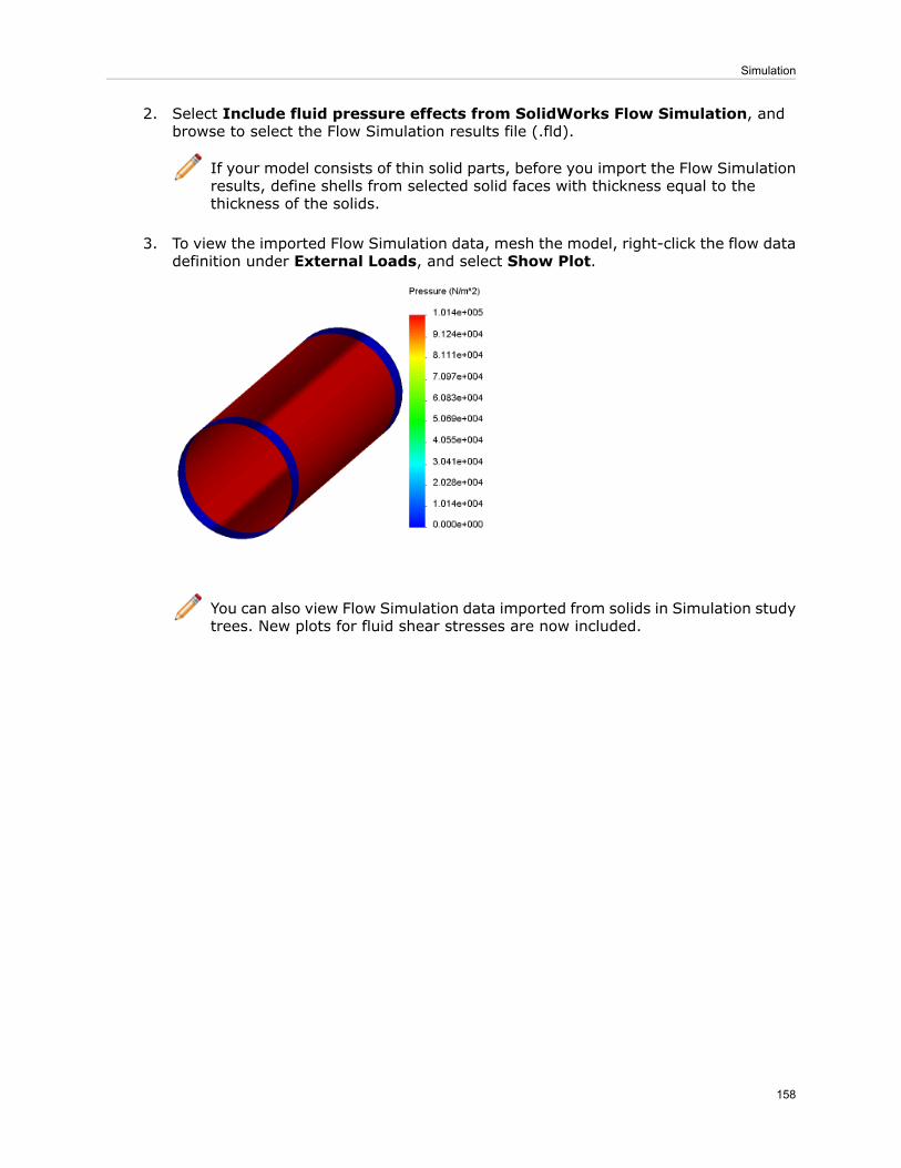
2. Select Include fluid pressure effects from SolidWorks Flow Simulation, andbrowse to select the Flow Simulation results file (.fld).
If your model consists of thin solid parts, before you import the Flow Simulationresults, define shells from selected solid faces with thickness equal to thethickness of the solids.
3. To view the imported Flow Simulation data, mesh the model, right-click the flow datadefinition under External Loads, and select Show Plot.
You can also view Flow Simulation data imported from solids in Simulation studytrees. New plots for fluid shear stresses are now included.
158
Simulation

20Sketching
This chapter includes the following topics:
• Dimensions• Linear and Circular Sketch Patterns• Shortcut Menus• Sketch Rotation
Dimensions
Inserting DimensionsNew menu items are available on the shortcut menu when you right-click in a sketch.
Displays numeric input fields to specify sizes when creating sketchentities. This is the same option in Tools > Options > System
Sketch NumericInput
Options > Sketch called Enable on screen numeric input onentity creation.
Displays dimensions when creating sketch entities. Instead ofselecting Add dimensions in sketch PropertyManagers, you canright-click in the graphics area and click Add Dimension .
Add Dimension
Creates driven dimensions when creating sketch entities. This ishelpful when you want some dimensions to be driving and others
Sketch DimensionDriven
to be driven because you can switch between the dimension types.In SolidWorks 2011, you could only create driven dimensions afteryou placed the dimensions.
For Add Dimension and Sketch Dimension Driven to appear in the shortcut menu,when you are using a sketch tool, right-click in the graphics area and click SketchNumeric Input .
See SolidWorks Help: Displaying Dimensions and Inserting Driven Dimensions.
Over Defined SketchesWhen you sketch the last entity to create a closed-profile sketch, it may clash with inferredrelations from the other sketch entities. In this case, the dimension for the last sketchentity causes the sketch to be over defined. In SolidWorks 2012, the clashing dimensionis changed to a driven dimension.
159

SolidWorks 2011: The dimension on the leftvertical line causes the sketch to be over
defined
SolidWorks 2012: The dimension on the leftvertical line that causes the sketch to be
over defined is changed to driven
UndoWhen creating dimensions with the Smart, Horizontal, or Vertical Dimension tools,you can undo previous selections by pressing Esc.
For example, when dimensioning multiple entities using the Smart Dimension tool,you can press Esc to undo the last selection. This is helpful if you accidentally select anentity that you did not want to dimension.
Using Centerlines to Create Radial and DiametricDimensionsYou can create multiple radial or diametric dimensions without selecting the centerlineeach time.
This type of dimensioning is helpful when you create sketches for revolved geometry thatrequire several diameter dimensions.
Multiple diametric dimensionsMultiple radial dimensions
160
Sketching

1. In a sketch with a centerline and lines or points, click Smart Dimension(Dimensions/Relations toolbar) or Tools > Dimensions > Smart.
2. Select the centerline and a line or point.3. To create a radius, move the pointer to the near side of the centerline. To create a
diameter, move the pointer to the far side of the centerline.4. Click to place the dimension.
The pointer changes to for radial dimensions and for diametric dimensions.
5. Select other lines or points in the sketch to create additional dimensions.
Linear and Circular Sketch Patterns
Downstream FeaturesIf you rebuild a linear or circular sketch pattern that has downstream features that dependon the pattern, relations or references to the pattern are maintained.
Dimensions in Linear and Circular PatternsOptions in the Linear Pattern and Circular Pattern PropertyManagers have changed.
In the Linear Pattern PropertyManager, the option Add spacing dimension is renamedto Dimension X spacing (for Direction 1) and Dimension Y spacing (for Direction2). The option Add angle dimension between axes is renamed to Dimension anglebetween axes. These options are available when creating or editing linear patterns.
In the Circular Pattern PropertyManager, the option Add spacing dimensions is splitinto two different options:
Displays the circular pattern radius.Dimension radius
Displays the dimension between the patterninstances.
Dimension angular spacing
These options are available when creating or editing circular patterns.
Shortcut MenusWhen sketching, the shortcut menu is longer so it displays more sketch and relationstools for ease of use and improved workflow.
161
Sketching
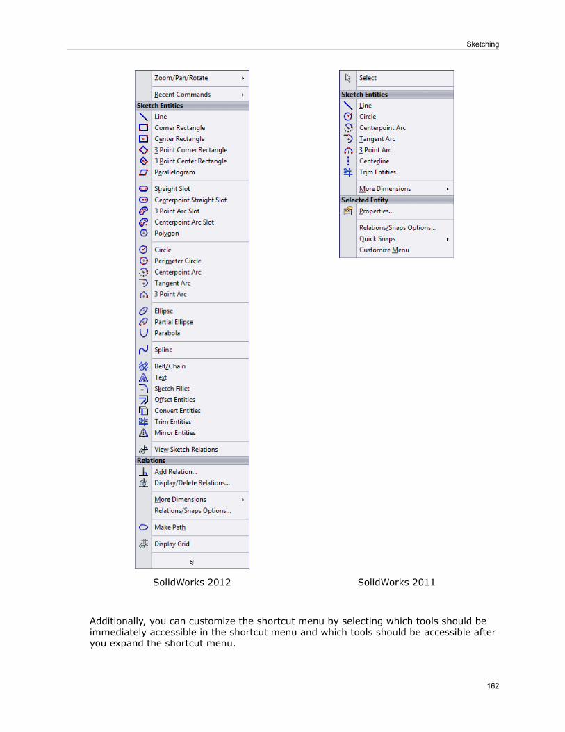
SolidWorks 2011SolidWorks 2012
Additionally, you can customize the shortcut menu by selecting which tools should beimmediately accessible in the shortcut menu and which tools should be accessible afteryou expand the shortcut menu.
162
Sketching

In a sketch, right-click to display the shortcut menu. In the shortcut menu, click , thenCustomize Menu to edit the menu.
Sketch RotationYou can set an option to automatically rotate 2D sketches to be normal to the sketchplane.
Click Tools > Options > System Options > Sketch and select Auto-rotate viewnormal to sketch plane on sketch creation. Whenever you open a sketch on a plane,the view rotates so it is normal to the plane.
163
Sketching
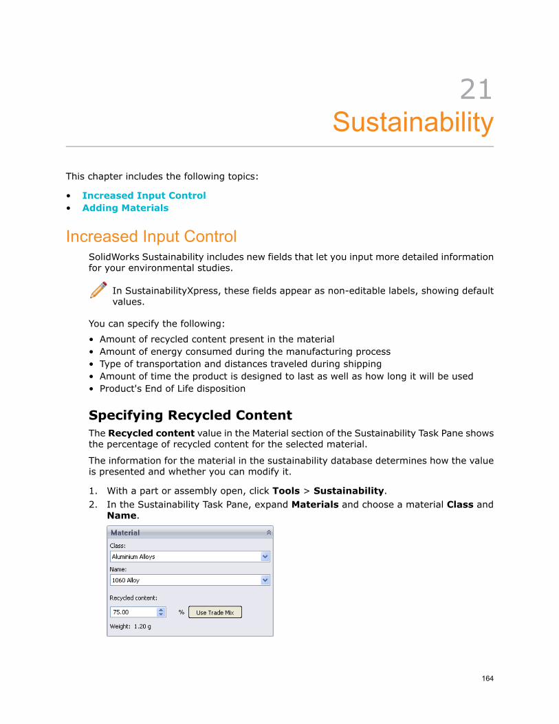
21Sustainability
This chapter includes the following topics:
• Increased Input Control• Adding Materials
Increased Input ControlSolidWorks Sustainability includes new fields that let you input more detailed informationfor your environmental studies.
In SustainabilityXpress, these fields appear as non-editable labels, showing defaultvalues.
You can specify the following:
• Amount of recycled content present in the material• Amount of energy consumed during the manufacturing process• Type of transportation and distances traveled during shipping• Amount of time the product is designed to last as well as how long it will be used• Product's End of Life disposition
Specifying Recycled ContentThe Recycled content value in the Material section of the Sustainability Task Pane showsthe percentage of recycled content for the selected material.
The information for the material in the sustainability database determines how the valueis presented and whether you can modify it.
1. With a part or assembly open, click Tools > Sustainability.2. In the Sustainability Task Pane, expand Materials and choose a material Class and
Name.
164

If the sustainability database contains primary (virgin), secondary (recycled), andtrade mix (default mix of virgin and recycled content) values for the material youchose, the Recycled content field shows the percentage of recycled content.
3. To change the amount of recycled material, specify a new percentage.
The control becomes yellow and the Use Trade Mix button becomes active.
4. To revert to the default trade mix, click Use Trade Mix.
Specifying Manufacturing and Assembly DetailsYou can now specify additional details for use in evaluating the sustainability ofmanufacturing or assembly processes. New controls let you specify the expected lifetimeof a part or assembly, the processes used to manufacture it, and the energy used in eachprocess.
Defining the Manufacturing Process for a Part
1. With a part open, click Tools > Sustainability.2. Expand the Manufacturing section of the Sustainability Task Pane.
3. Select the manufacturing region from the Region drop-down list or by clicking theregion in the map.
4. Under Built to last, enter a time increment and value to represent the expected lifespan of the part. For example, 10.00 and Year, indicating 10 years of life expectancy.
5. Under Process, select the manufacturing process to be used.
The initial values in the editable fields for electricity use, natural gas use, and scraprate are calculated based on the part's material and the manufacturing process youselect.
The totals under each field are calculated based on the part's weight.
165
Sustainability
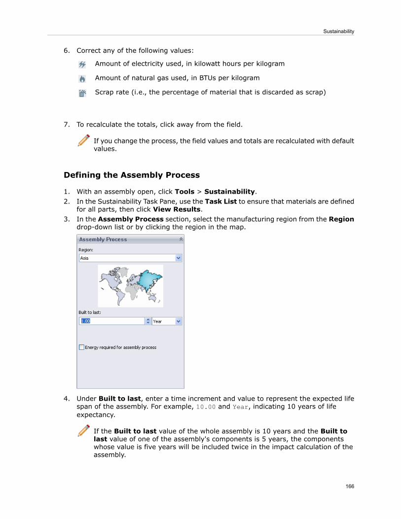
6. Correct any of the following values:
Amount of electricity used, in kilowatt hours per kilogram
Amount of natural gas used, in BTUs per kilogram
Scrap rate (i.e., the percentage of material that is discarded as scrap)
7. To recalculate the totals, click away from the field.
If you change the process, the field values and totals are recalculated with defaultvalues.
Defining the Assembly Process
1. With an assembly open, click Tools > Sustainability.2. In the Sustainability Task Pane, use the Task List to ensure that materials are defined
for all parts, then click View Results.3. In the Assembly Process section, select the manufacturing region from the Region
drop-down list or by clicking the region in the map.
4. Under Built to last, enter a time increment and value to represent the expected lifespan of the assembly. For example, 10.00 and Year, indicating 10 years of lifeexpectancy.
If the Built to last value of the whole assembly is 10 years and the Built tolast value of one of the assembly's components is 5 years, the componentswhose value is five years will be included twice in the impact calculation of theassembly.
166
Sustainability

5. If you want to specify the energy usage to build the assembled product, select Energyrequired for assembly process.
6. In the Fuel type drop-down list, select Electricity or Natural Gas.7. In the Amount field, type the amount of energy you expect to be used.
Specifying Part and Assembly Use ParametersA new Use section of the Sustainability Task pane lets you specify the where the productwill be used. For assemblies, this is where you now indicate the energy needs of theproduct over its lifespan.
For a part, in the Use section, select the manufacturing region from the Region drop-downlist or by clicking the region in the map.
To provide assembly Use parameters:
1. With an assembly open, click Tools > Sustainability.2. In the Sustainability Task Pane, use the Task List to ensure that materials are defined
for all parts, then click View Results.3. In the Use section of the Sustainability Task pane, select the manufacturing region
from the Region drop-down list or by clicking the region in the map.
4. If you want to specify the energy used during the lifetime of the product, selectEnergy needs over lifespan.
5. In the Type of Energy drop-down list, select from:
• Electricity• Natural Gas• Diesel
167
Sustainability

• Gasoline• Kerosene• Light Fuel Oil
6. Specify the Amount of energy and select a time increment. For example, selectingDiesel, typing 2.00 and selecting Hour, indicates that the product will use 2.00gallons of diesel fuel per hour during its lifetime.
Specifying Shipping DetailsFor both parts and assemblies, the Transportation section of the Sustainability TaskPane lets you identify shipping methods and distances.
1. In the Sustainability Task Pane, expand Transportation.
Default shipping distances are based on the Use Region selected.
The units are given in kilometers or miles, depending on whether the units for thepart's weight are metric.
2. Click a button to enable editing of its value.You can edit any or all of the following:
Train
Truck
Boat
Plane
3. Specify the distance traveled for the selected transportation mode.Changing a value highlights the new value in yellow and enables the Reset toDefaults button, which you can use to return to the default transportation settingsfor the current Use Region.
168
Sustainability
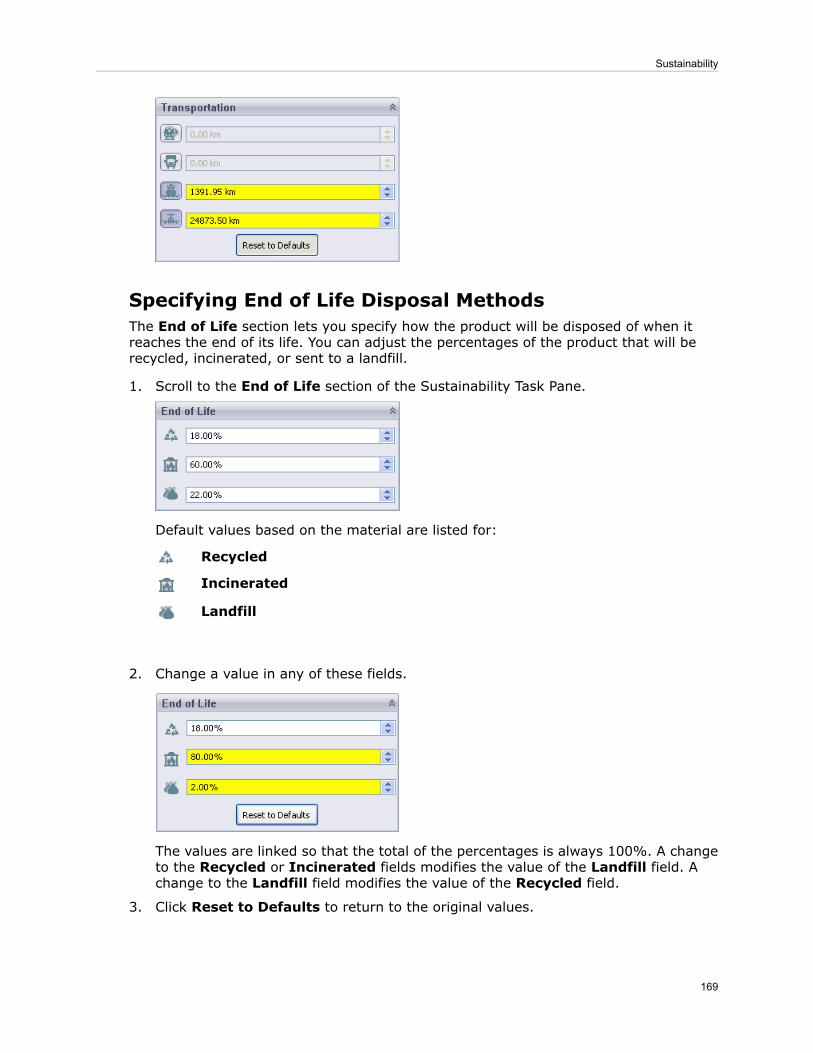
Specifying End of Life Disposal MethodsThe End of Life section lets you specify how the product will be disposed of when itreaches the end of its life. You can adjust the percentages of the product that will berecycled, incinerated, or sent to a landfill.
1. Scroll to the End of Life section of the Sustainability Task Pane.
Default values based on the material are listed for:
Recycled
Incinerated
Landfill
2. Change a value in any of these fields.
The values are linked so that the total of the percentages is always 100%. A changeto the Recycled or Incinerated fields modifies the value of the Landfill field. Achange to the Landfill field modifies the value of the Recycled field.
3. Click Reset to Defaults to return to the original values.
169
Sustainability

Environmental Impact Dashboard ChangesOn the Environmental Impact dashboard, a new Duration of Use field lets you specify
the length of time a product will be used. A Home button makes it easy to return tothe initial view of the dashboard.
Duration of UseWhen sustainability is calculated, the Duration of Use value is used in conjunction withthe Built to last value you specify in the Manufacturing section.
To get a more accurate picture of the impact of a design, the Duration of Use value isdivided by the Built to last value. The result is rounded to the next whole number.
For example, if a product is built to last four years and its duration of use is 10 years,the calculation is 10 / 4 = 2.5, rounded up to 3. This means that to have the use of theproduct for 10 years, you will need a quantity of three. So the net impact on allenvironment results is three times that of a single product.
Conversely, if a product is built to last for 10 years and it's duration of use is one year,the calculation is 1 / 10 = .01, rounded up to 1. This means you will only need a quantityof one to satisfy the duration of use.
Duration of Use and Built to last have been added to reports and the CustomColumn choices for Assembly Visualization.
Navigation
The Previous and Next buttons from earlier versions of Sustainability have been
replaced by a Home button.
Clicking Home when you are viewing environmental impact details such as CarbonFootprint or Energy Consumption returns you to the initial display of theEnvironmental Impact dashboard, showing the summary pie charts.
170
Sustainability

Bar GraphsArrows have been added to the bar graphs below the pie charts on the dashboard Homepage. They emphasize the increase or decrease in environmental impact.
Adding MaterialsYou can access additional materials for Sustainability studies using the SustainabilityExtras folder in the SolidWorks Materials dialog box.
You can download additional materials and request materials that are not yet available.
Updating the Materials DatabaseWhen a new version of the Sustainability database is available, you can download it fromthe Material dialog box.
1. With a part open, in the FeatureManager design tree, right-click Material andselect Edit Material.
2. In the Material dialog box, in the left pane, click Sustainability Extras.The Properties tab in the right pane shows the latest version of the GaBi SustainabilityDatabase and when you last checked for updates.
3. Click Check for Updates.The Check for Updates dialog box tells you whether an update to the database isavailable.
4. If an update is available, click Update.5. When the download is complete, click OK.
The database version is updated and the added materials are listed under SustainabilityExtras.
You can edit the material as you would any other material. If you make changes, theyare preserved when you update the database again.
When you use Sustainability, the materials you have added appear in the following places:
The Class drop-down list identifies the addedmaterial class with a Sustainability Extras prefix.
When you select a material for a part
When you select -any- as a Material Class, theresults that match the specified criteria includematerials from the Sustainability Extras folder.
In theFind Similar Material dialog box
171
Sustainability

Requesting MaterialsIf the Materials dialog box does not contain a material you need, you can request thatthe material be added.
1. In the FeatureManager design tree, right-click Material and select Edit Material.2. In the Material dialog box, in the left pane, click Sustainability Extras.3. On the Properties tab in the right pane, to see a listing of available materials, click
Check online listing.
A Web page opens, listing the SolidWorks materials that are currently defined in thesustainability database and what you can model with them.
4. To request that a material be added to the database, click Submit a Request.
The Request a Material form on the SolidWorks Sustainability Website appears.The form includes a list of recent material requests and their status.
5. Complete and submit the form.6. When you are notified that the material you requested has been added, click Check
for Updates to download the latest updates.
172
Sustainability

22Toolbox
Available in SolidWorks Professional and SolidWorks Premium.
This chapter includes the following topics:
• Performance and Customization Enhancements
Performance and Customization EnhancementsTo permit more flexible Toolbox customization and to improve performance, Toolboxcomponent information is now stored in each part file rather than in a Microsoft Accessdatabase. For example, from Toolbox Settings, you can assign components to folders youcreate and you can rename files. You can also modify components within the defaultstandards.
To open Toolbox Settings, click SolidWorks version > SolidWorks Tools > ToolboxSettings from the list of all programs on the Start menu of your computer.
See SolidWorks Help: Configuring Toolbox for more information.
Customizing ToolboxYou can customize Toolbox content from the Customize Hardware page of Toolbox Settingsby copying, pasting, deleting, and renaming Toolbox folders.
In this example, you create a new Toolbox folder, add content to it, rename content, anddelete content from it.
Your Toolbox administrator might have already customized Toolbox for you. Consultyour Toolbox administrator before you perform this exercise.
First, open Toolbox Settings to begin hardware customization.
To open Toolbox Settings, click SolidWorks version > SolidWorks Tools > ToolboxSettings from the list of all programs on the Start menu of your computer.
173
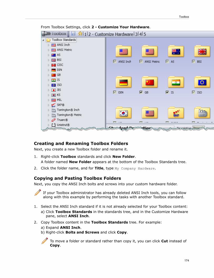
From Toolbox Settings, click 2 - Customize Your Hardware.
Creating and Renaming Toolbox FoldersNext, you create a new Toolbox folder and rename it.
1. Right-click Toolbox standards and click New Folder.A folder named New Folder appears at the bottom of the Toolbox Standards tree.
2. Click the folder name, and for Title, type My Company Hardware.
Copying and Pasting Toolbox FoldersNext, you copy the ANSI Inch bolts and screws into your custom hardware folder.
If your Toolbox administrator has already deleted ANSI Inch tools, you can followalong with this example by performing the tasks with another Toolbox standard.
1. Select the ANSI Inch standard if it is not already selected for your Toolbox content:a) Click Toolbox Standards in the standards tree, and in the Customize Hardwarepane, select ANSI Inch.
2. Copy Toolbox content in the Toolbox Standards tree. For example:a) Expand ANSI Inch.b) Right-click Bolts and Screws and click Copy.
To move a folder or standard rather than copy it, you can click Cut instead ofCopy.
174
Toolbox

3. Right-click the My Company Hardware folder in the Toolbox Standards tree andclick Paste.A copy of the Bolts and Screws folder appears under My Company Hardware.
When you copy and paste Toolbox content, a number is appended to the Toolboxfilenames so that they remain unique. Cutting and pasting does not modifyToolbox filenames.
Copying standard Toolbox content from one folder to another does not affectsmart fastener assignment. For each hole type, you can reassign smart fasteners.
Renaming Toolbox Content and Deleting FoldersNext, you modify the filename for Toolbox content in your custom Toolbox content folderand delete unnecessary content.
For this example, suppose your assemblies reference two types of heavy hex bolts. Todifferentiate the heavy hex bolts in your custom Toolbox content folder from those in theANSI Inch folder, you can change the filename and title assigned to the heavy hex boltsin your custom Toolbox content folder. In addition, suppose your company never usesround head bolts. You can remove round head bolts from your custom Toolbox contentfolder.
1. In theMy Company Hardware folder in the Toolbox Standards tree, expand Boltsand Screws.
2. Expand Hex Head and select Heavy Hex Bolt.3. In the Heavy Hex Bolt properties pane, change the filename and title:
a) For Filename, type My Favorite ANSI Inch Hex Bolt.sldprt.
All Toolbox filenames must be unique. You cannot assign a filename thatconflicts with the name of another Toolbox file.
b) For Title change Heavy Hex Bolt to My Favorite ANSI Inch Hex Bolt.
The part Title affects only the name displayed in the Toolbox Standardstree and not the part filename.
4. Remove the round head bolt folder from the My Company Hardware folder:a) Right-click the Round Head Bolts folder and click Delete.b) Click OK.
5. Close Toolbox Settings.6. When prompted to save changes, do one of the following:
• To save your changes, click Yes.• To discard your changes, click No.
You can perform similar operations to move folders around, rename folders and tools,and delete unnecessary tools or folders.
175
Toolbox

If you do not use the ANSI Inch standard at your company, select ToolboxStandards and clear the ANSI Inch standard after you complete this example.
176
Toolbox
23Weldments
This chapter includes the following topics:
• Cut List Properties
Cut List PropertiesWhen you create subweldments, or when you save weldment bodies to new parts, thecut list properties from the parents propagate to the subweldments or new parts.
In the Cut-List Properties dialog box, the Value / Text Expression of the propertiesappear as Linked to Parent Part- parent .sldprt. You cannot edit the cut listproperties unless you break the reference to the parent part. To open the Cut-ListProperties dialog box, in the FeatureManager design tree, right-click a Cut-List-Itemand click Properties.
177

24SolidWorks Workgroup PDM
This chapter includes the following topics:
• Rebuilding Workgroup PDM Vault Metadata• Accessing the Workgroup PDM Vault from Windows 7 and Windows Vista• Pack and Go Improvements
Rebuilding Workgroup PDM Vault MetadataThe Rebuild Vault option in the SolidWorks Workgroup PDM VaultAdmin tool lets yourebuild vault metadata from key base files.
Before rebuilding a vault, the recommended best practice is to create a backup orensure that your regularly scheduled backup is up to date.
You can improve the startup time of the vault by running the Rebuild Vault option onceor twice a month on the system where the vault was created.
You should also run the Rebuild Vault option before migrating Workgroup PDM vaultdata to Enterprise PDM or exporting from a Workgroup PDM vault.
To rebuild the vault:
1. Log in to the Workgroup PDM vault as a user with administrator privileges.2. On the Vault Settings tab, under Vault Lock, click Locked to lock all users out of thevault.
3. Click Rebuild Vault.4. In the Repair options dialog box, select rebuild options and click OK.5. When warned that the vault will be shutdown, click Yes.
Accessing the Workgroup PDM Vault from Windows 7 andWindows Vista
The SolidWorks Open dialog box allows Windows 7 and Windows Vista users to accessWorkgroup PDM vaults.
A secondary dialog box lets you search in the Workgroup PDM vault and check out filesor get the latest file. When you select a file, the SolidWorks Open dialog box lets youopen the file as if it were a local file.
To access Workgroup PDM vault files:
1. In SolidWorks, click File > Open.2. In the Open dialog box, click Browse vault.3. In the Select from Vault dialog box, select a file and do any of the following:
178

To preview the file, select Thumbnail.•• To check out the file without using other options, select the Check Out check boxand then click Checkout.
• To see additional Workgroup PDM options, click Check Out Advanced or clearCheck Out and click Select Advanced.
The Get Local Copy and Open Document dialog box opens.
When you check out a file directly or select Open/Check Out from the Get Local Copyand Open Document dialog box, the SolidWorks Open dialog box reappears with thefile listed as a local document.
4. Select additional options from the SolidWorks Open dialog box options and click Open.
Pack and Go ImprovementsWhen you run Pack and Go, a progress bar reports the steps in the Pack and Go process.The Cancel button remains active so you can cancel after beginning the operation.
In addition, Pack and Go provides improved support for non-ASCII characters in filenames.
In the Pack and Go dialog box, the progress bar and Cancel button become active whenyou click Save to start the process of creating the package.
179
SolidWorks Workgroup PDM