wheel balancer - snap-on equipment · function code settings ... c-function and error code quick...
TRANSCRIPT
WHEEL BALANCER
8.6 SEMI-AUTOMATIC8.7 AUTOMATIC
Service Manual
September, 1998
All information contained or disclosed in this documentis considered confidential and proprietary by Snap-OnTools Company. All manufacturing, use, reproduction,and sales rights are reserved by Snap-On ToolsCompany and the information contained herein shall notbe used in whole or in part without the express writtenconsent of Snap-on Tools Company.


309 EXCHANGE AVE.CONWAY, ARKANSAS 72032
0692-9635(09/1998) 1998 EquiServ Printed in U.S.A.
TABLE OF CONTENTS FOR 8 SERIES WHEEL BALANCER
Effective9/98
INTRODUCTION
GENERAL .......................................................................................................................................................... I
FUNCTIONAL DESCRIPTION............................................................................................................................ I
DISPLAY / CONTROL / PANEL ............................................................................................................. iELECTRICAL SAFETY PRECAUTIONS ........................................................................................................... II
SERVICE GUIDELINES / HANDLING / STATIC SENSITIVE DEVICES ............................................................ II
CHAPTER 1 AC/DC POWER DISTRIBUTION
AC THEORY OF OPERATION.......................................................................................................................1-1AC DISTRIBUTION............................................................................................................................1-1
DC THEORY OF OPERATION.......................................................................................................................1-1INDIVIDUAL COMPONENT TESTING ...........................................................................................................1-1
TRANSFORMER RESISTANCE AND OUTPUT TESTING................................................................1-2MOTOR CONTROL PCB RELAY TESTING ......................................................................................1-2START CAPACITOR TESTING .........................................................................................................1-2RIBBON CABLE TESTING ................................................................................................................1-3BRAKE RECTIFIER (POSITIONING TESTING) ................................................................................1-3RELAY DIODE TESTING...................................................................................................................1-3MOTOR TESTING.............................................................................................................................1-3
TROUBLESHOOTING....................................................................................................................................1-4
CHAPTER 2 THEORY OF OPERATION
EQUIPMENT OPERATION DESCRIPTION ...................................................................................................2-1GENERAL BALANCER INFORMATION ............................................................................................2-1
OPERATING CYCLE DESCRIPTION.............................................................................................................2-2INITIAL TURN ON TESTS .................................................................................................................2-2CUSTOMER CALIBRATION, C14C ...................................................................................................2-2INDIVIDUAL COMPONENT OPERATION .........................................................................................2-2
FUNCTION CODE SETTINGS .......................................................................................................................2-3SELECTING CODES .........................................................................................................................2-3STORING CODES.............................................................................................................................2-3FUNCTION CODES...........................................................................................................................2-3
CHAPTER 3 INSTALLATION, CALIBRATION, AND MAINTENANCE
GENERAL ......................................................................................................................................................3-1INSTALLATION PROCEDURES ....................................................................................................................3-1
SELECTION OF MACHINE TYPE .....................................................................................................3-1RIM DISTANCE GUAGE ADJUSTMENT JBC 8.6/8.7 SERIES..........................................................3-2RIM DIAMETER GAUGE ADJUSTMENT JBC 8.6 / 8.7 SERIES........................................................3-2RIM WIDTH GAUGE ADJUSTMENT, JBC 8.7 ONLY ........................................................................3-4C18C / C19C FINE ADJUSTMENT OF RIM DIAMETER AND RIM WIDTH GAUGES - JBC 8.6 & 8.73-5READOUT ADJUSTMENT (BASIC CALIBRATION)...........................................................................3-6SHAFT BALANCE PROCEDURE ......................................................................................................3-7THEORY OF OPERATOR CALIBRATION.........................................................................................3-7OPERATOR CALIBRATION PROCEDURE .......................................................................................3-8
CHAPTER 4 PARTS
PARTS BY PICTORIAL..................................................................................................................................4-1DRIVE SUSPENSION AASSEMBLY..................................................................................................4-1EXPLODED VIEW .............................................................................................................................4-2WHEEL GUARD ASSEMBLY ............................................................................................................4-3PCB VIEW.........................................................................................................................................4-4CENTERING DEVICE EXPLODED VIEW..........................................................................................4-5
PARTS IN ALPHABETICAL ORDER ..............................................................................................................4-6PARTS IN NUMERICAL ORDER....................................................................................................................4-9
TABLE OF CONTENTS FOR 8 SERIES BALANCER
Effective9/98
CHAPTER 5 ACCURACY TEST, DIAGNOSTIC CODES, AND TEST PROCEDURES
ACCURACY TESTS.......................................................................................................................................5-1SHAFT IMBALANCE, WHEEL ADAPTER TO SHAFT REMOUNT TEST ..........................................5-1WHEEL ADAPTER COMPONENTS - CENTER CONE ADAPTER REMOUNT TEST .......................5-2TESTING BALANCER READOUT ACCURACY - WEIGHT AMOUNT AND LOCATION....................5-3DIAGNOSIS AND TEST CODE LIST.................................................................................................5-4EXPLANATION OF DIAGNOSIS CODES ..........................................................................................5-5PARTS REPLACEMENT - WHEN IS READJUSTMENT OR RECALIBRATION NECESSARY..........5-8
APPENDIX A ERROR MESSAGES
ERROR MESSAGES..................................................................................................................................... A-1
APPENDIX B SOFTWARE / HARDWARE REVISION
SOFTWARE REVISIONS.............................................................................................................................. B-1HARDWARE REVISIONS ............................................................................................................................. B-2
APPENDIX C KIT INSTALLATION INSTRUCTIONS
INSTALLATION INSTRUCTIONS.................................................................................................................. C-1
Effective8/98 Page i
INTRODUCTION
GENERAL
Use the John Bean 8.6 / 8.7 balancer to:
1. Perform off the car balancing of tires to the nearest 0.25 oz. (7 grams) in normal mode, 0.05 oz. (1 gram) in
fine mode.
2. Match balance tires using the Pro Match tire matching procedure. This procedure should be used when the
Pro Match indicator is lit after a measuring run is completed. The process may be initiated on any wheel by
pressing the OP key. See the Operator’s Manual for procedures.
FUNCTIONAL DESCRIPTION
Parameter Entry: Enter wheel parameters using the Distance / Diameter Parameter Entry Arm. Slide the gaugeto touch the rim and hold it for one second. The distance to the rim and diameter of the wheel will be enteredautomatically. Measure the rim width with the rim width calipers (supplied), press the Rim Width key once, andenter the measured value. For example, for a 6 ½” wheel, enter 6.5 using the keypad. On 8.7 balancers, awheel width parameter entry arm is attached to the right hand side of the hood. Grasp the arm, touch the gaugeto the right side of the wheel and hold for one second. Wheel width will be entered automatically.
Basic Balancer Operation: Close the hood and press the START button. The wheel assembly will spin.Imbalance in the assembly will be measured and the machine will automatically brake to a stop. Imbalances andcounterbalance locations will be shown on the display.
Weight Application: The wheel will automatically stop close to the location of the required counterbalance weightfor the right hand plane. Rotate the wheel until the UP / DOWN arrow led’s turn off, leaving only the – (dash) inthe middle. Apply a proper counter weight at top dead center on the side indicated. Repeat for the oppositeplane of the wheel.
Pro Match Procedure: Pro Match was developed to reduce lateral and radial runout of, and force variations on,wheel assemblies. Using the Pro Match procedure is recommended if:
1. The Pro Match indicator is illuminated after a measuring run.2. The wheel requires large balancing weights.3. Radial or lateral runout is excessive as the wheel rotates on the balancer.4. The vehicle is known to be sensitive to runout or force variations.5. Customer complaints occur after accurate conventional balancing procedures.
The Pro Match procedure allows the computer to determine the best location of the tire on the wheel. Pro Match
will reduce runout, both radial and lateral, and will reduce the amount of counterbalance weights required to
correctly balance a wheel assembly. See the Operator’s Manual for specific systematic procedures.
DISPLAY / CONTROL PANELThe 8.7 / 8.6 balancer LED display shows the weight amount and position required for counterbalancing wheelassemblies, the positions for weight application, and icons for individual distance, diameter, and width values.Icons for Pro Match and for Zero Compensation of the Basic Centering Device are also shown.
INTRODUCTION
EffectivePage ii 9/98
Control of balancer functions is via keypads for STOP, START, and inputs. Pressing and holding STOP gives ahigh resolution display readout (to the nearest 0.05 oz. or 1-gram). See the Operator’s Manual for a summary ofcontrol functions.
ELECTRICAL SAFETY PRECAUTIONS
208 to 230 VAC is present inside this equipment. Danger of shock hazard is present. Use the “One Hand Rule”when working with high AC voltages by keeping one hand in your pocket or behind your back when working onthis equipment. Make sure the balancer is turned “OFF” before disconnecting any wires in preparation forreplacing any boards, cables, or other items within the unit,.
SERVICE GUIDELINES / HANDLING STATIC SENSITIVE DEVICES
Electrostatic discharge can destroy high impedance ICs if uncontrolled. Use the following techniques to avoiddamaging these ICs:
• Leave new circuit boards in their antistatic bags until ready for use.• When replacing boards, proms, etc. be sure to turn off power to the machine first!ü Leave the machine plugged in (to provide a ground circuit) when servicing the equipment.ü Use an anti-static wrist strap. Connect it to chassis ground on the equipment or to an available raw
ground.ü Touch the chassis of the equipment to put yourself at the same static potential as the equipment.ü Grasp the PCB from opposite sides using your fingertips. Do not grasp the components on the board.ü Place boards on a grounded static mat after removal.
• When inserting PCB’sü Remove the new PCB from the original package onto a grounded static mat. Save packaging to use
when returning defective boards.ü Remove power from the machine (turn it off) before installing the PCB.
• Avoid handling components needlessly.• Do not set PCBs on insulating surfaces such as paper, glass, rubber, or plastic.• Static is generated by friction. The following actions promote static generation:ü Wearing silk or nylon clothing.ü Walking on carpets.ü Walking with rubber soled shoes.
Static generation is increased when environmental conditions are correct. Conditions of low humidity combinedwith wearing silks or nylons, walking on carpets, or walking with rubber soled shoes may create large electrostaticcharges on your person, capable of blowing a hole in the substrate of an IC.
!DANGEROUSLY HIGH VOLTAGES
ARE PRESENT IN THIS EQUIPMENT
INTRODUCTION
Effective9/98 Page iii
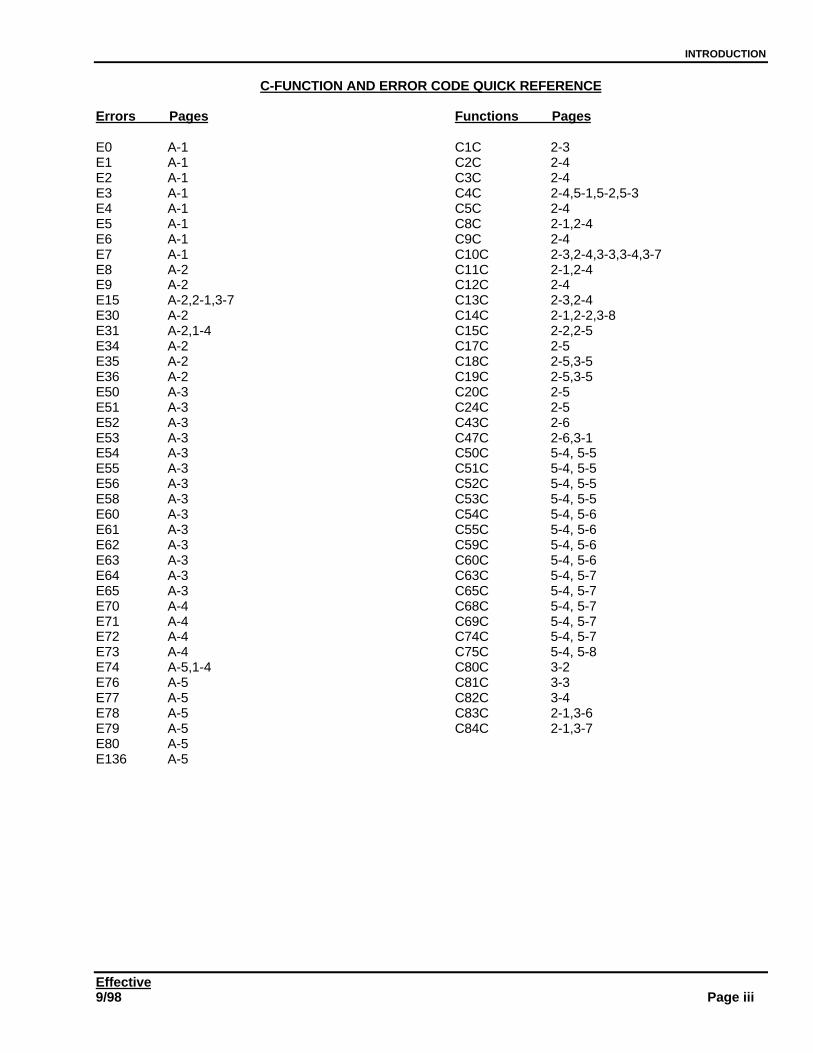
C-FUNCTION AND ERROR CODE QUICK REFERENCE
Errors Pages
E0 A-1E1 A-1E2 A-1E3 A-1E4 A-1E5 A-1E6 A-1E7 A-1E8 A-2E9 A-2E15 A-2,2-1,3-7E30 A-2E31 A-2,1-4E34 A-2E35 A-2E36 A-2E50 A-3E51 A-3E52 A-3E53 A-3E54 A-3E55 A-3E56 A-3E58 A-3E60 A-3E61 A-3E62 A-3E63 A-3E64 A-3E65 A-3E70 A-4E71 A-4E72 A-4E73 A-4E74 A-5,1-4E76 A-5E77 A-5E78 A-5E79 A-5E80 A-5E136 A-5
Functions Pages
C1C 2-3C2C 2-4C3C 2-4C4C 2-4,5-1,5-2,5-3C5C 2-4C8C 2-1,2-4C9C 2-4C10C 2-3,2-4,3-3,3-4,3-7C11C 2-1,2-4C12C 2-4C13C 2-3,2-4C14C 2-1,2-2,3-8C15C 2-2,2-5C17C 2-5C18C 2-5,3-5C19C 2-5,3-5C20C 2-5C24C 2-5C43C 2-6C47C 2-6,3-1C50C 5-4, 5-5C51C 5-4, 5-5C52C 5-4, 5-5C53C 5-4, 5-5C54C 5-4, 5-6C55C 5-4, 5-6C59C 5-4, 5-6C60C 5-4, 5-6C63C 5-4, 5-7C65C 5-4, 5-7C68C 5-4, 5-7C69C 5-4, 5-7C74C 5-4, 5-7C75C 5-4, 5-8C80C 3-2C81C 3-3C82C 3-4C83C 2-1,3-6C84C 2-1,3-7
INTRODUCTION
EffectivePage iv 9/98
Effective9/98 Page 1
CHAPTER 1 AC / DC POWER DISTRIBUTION
AC THEORY OF OPERATION
Always use the “One Hand Rule” when working with AC voltages by keeping one hand in your pocket or behindyour back. Before disconnecting any wires or unplugging any PCBs in the 8.6 / 8.7 balancer, make sure thebalancer is OFF, and the unit is UNPLUGGED from the wall.
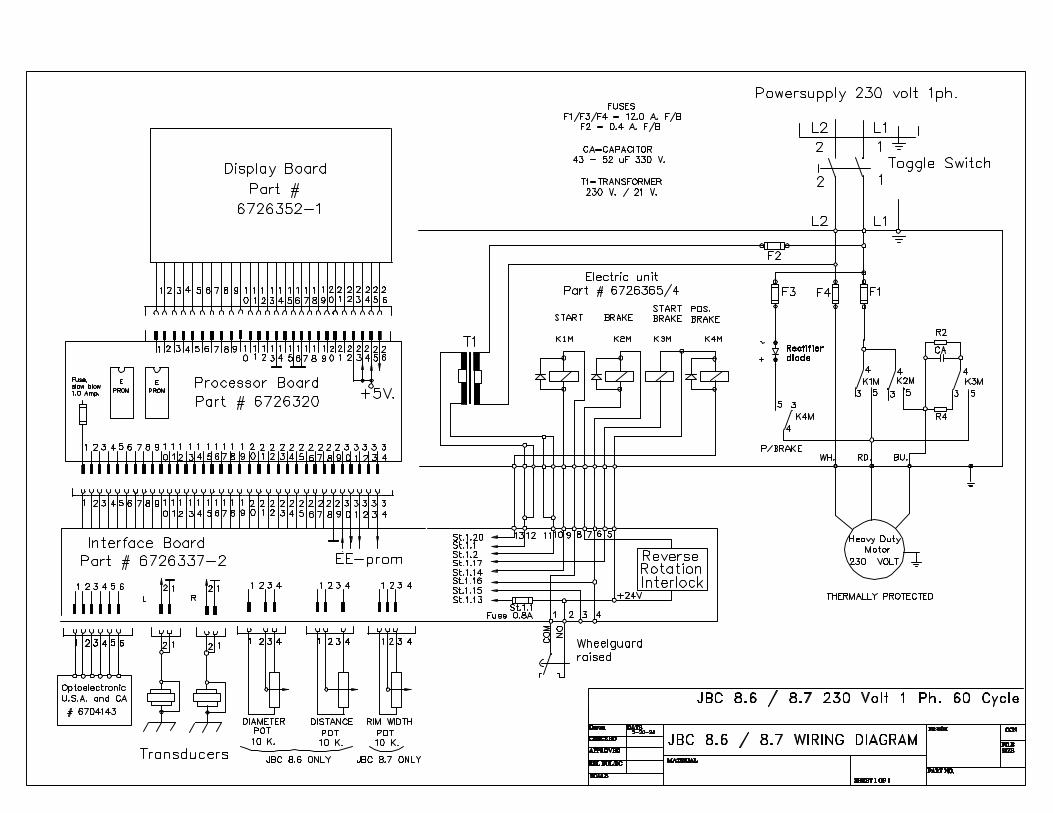
AC DISTRIBUTIONPrimary voltage to the machine is 208 / 230 VAC single phase nominal, 60 hz. A 20-ampere circuit is advised onthese machines. Actual amperage draw is less than 15 amps under normal operating conditions.
When turned on, 230 VAC is routed to the motor and the Motor Control PCB. The transformer takes the 230 VACinput and reduces it to 19-26 VAC output.
Fast Blow fuses F1 and F4 protect the motor in case of severe current surges. These fuses are rated at 12.0Amperes, 250 VAC. Motor control (spin) is controlled by K1M relay via inputs from the Processor PCB. K3Mbrings the motor start capacitor into the circuit.
Spin brake is controlled by relay K2M using inputs from the Processor. Spin braking is accomplished by reversingthe motor until a stop condition is seen by the encoder system. A rectifier diode used in conjunction with the K4Mrelay provides positioning braking, if the software for this function is turned on. Fast Blow fuse F3 (12.0 Amp / 250VAC) protects the position brake circuit.
Fuse F2 protects the transformer primary from over-voltage conditions. This is a 0.4A, 250 VAC quick blow fusewhich protects all downstream PCB’s, the Interface PCB, Processor PCB and Display PCB.
The OFF/ON switch doubles as an input block for 230 VAC and as the main power disconnect.
DC THEORY OF OPERATION
From the Interface PCB, 24 VDC, 12VDC, and 5VDC are provided to various parts of the machine. Thesebalancers have no integrated test points, and voltage tests are limited in value - see wiring diagram.
INDIVIDUAL COMPONENT TESTING
Voltage checks comprise a very small part of troubleshooting these units. Most checks are intended to be donewith power off, utilizing known resistances as references. Substitution of known good parts into the system is anacceptable form of troubleshooting these machines.
The following pages outline tests that may be made with power off to check individual components of thebalancer. Please follow all instructions precisely to ensure good results.
Page 1-1
!DANGEROUSLY HIGH VOLTAGES
ARE PRESENT IN THIS EQUIPMENT
CHAPTER 1 – AC/DC POWER DISTRIBUTION
EffectivePage 1-2 9/98
!DISCONNECT MACHINE FROM POWER SOURCE BEFORE
PERFORMING ANY OF THE FOLLOWING TESTS!
Transformer Resistance and Output Testing:
1. To test transformer resistance, remove fuse F2 from electric board. Set your multimeter to ohms, and select the appropriate scale.
A: Transformer primary resistance.ü Place meter leads on L2 terminal and load side of fuse F2.ü Resistance should be approximately 100 - 110 ohms.
B: Transformer secondary resistance.ü Remove ribbon cable leads #12 and #11 from the interface board.ü Place meter leads across these wires, #12 and #11.ü Resistance should be approximately 1.5 - 2.0 ohms.
2. To test output voltage of the transformer, install fuse F2, set meter to V-AC, and select the appropriate range. Leaving ribbon cable leads #12 and #11 disconnected from the interface board, place meter leads across the wires and turn on machine.ü Voltage should be approximately 19 - 26 vac.
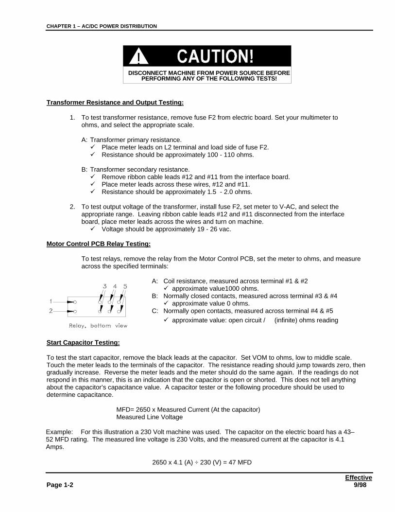
Motor Control PCB Relay Testing:
To test relays, remove the relay from the Motor Control PCB, set the meter to ohms, and measureacross the specified terminals:
A: Coil resistance, measured across terminal #1 & #2ü approximate value1000 ohms.
B: Normally closed contacts, measured across terminal #3 & #4ü approximate value 0 ohms.
C: Normally open contacts, measured across terminal #4 & #5ü approximate value: open circuit / ∝ (infinite) ohms reading
Start Capacitor Testing:
To test the start capacitor, remove the black leads at the capacitor. Set VOM to ohms, low to middle scale.Touch the meter leads to the terminals of the capacitor. The resistance reading should jump towards zero, thengradually increase. Reverse the meter leads and the meter should do the same again. If the readings do notrespond in this manner, this is an indication that the capacitor is open or shorted. This does not tell anythingabout the capacitor’s capacitance value. A capacitor tester or the following procedure should be used todetermine capacitance.
MFD= 2650 x Measured Current (At the capacitor)Measured Line Voltage
Example: For this illustration a 230 Volt machine was used. The capacitor on the electric board has a 43–52 MFD rating. The measured line voltage is 230 Volts, and the measured current at the capacitor is 4.1Amps.
2650 x 4.1 (A) ÷ 230 (V) = 47 MFD
CHAPTER 1 – AC/DC POWER DISTRIBUTION
Effective9/98 Page 1-3
Ribbon Cable Testing:
To test continuity of the ribbon cable, first disconnect the cable from the interface board. Set a VOM to readohms, and measure across the specified wires in both directions. The meter should read the indicatedvalue in at least one direction. Leave the relays on the Motor Control PCB during this test.
ü Wires #12 & #11 ~ 1.5 – 2.0 ohmsü Wires # 6 & # 5 ~ 1000 ohmsü Wires #10 & # 9 ~ 1000 ohmsü Wires # 13 & # 5 ~ 1000 ohmsü Wires # 8 & # 7 ~ 1000 ohms
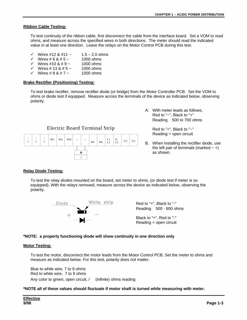
Brake Rectifier (Positioning) Testing:
To test brake rectifier, remove rectifier diode (or bridge) from the Motor Controller PCB. Set the VOM toohms or diode test if equipped. Measure across the terminals of the device as indicated below, observingpolarity.
A: With meter leads as follows,Red to "~", Black to "+"Reading ≅ 500 to 700 ohms
Red to "+", Black to "~"Reading = open circuit
B. When installing the rectifier diode, usethe left pair of terminals (marked ~ +)as shown.
Relay Diode Testing:
To test the relay diodes mounted on the board, set meter to ohms, (or diode test if meter is so equipped). With the relays removed, measure across the device as indicated below, observing the polarity.
Red to "+”, Black to "-"Reading ≅ 500 - 600 ohms
Black to "+”, Red to "-"Reading = open circuit
*NOTE: a properly functioning diode will show continuity in one direction only
Motor Testing:
To test the motor, disconnect the motor leads from the Motor Control PCB. Set the meter to ohms andmeasure as indicated below. For this test, polarity does not matter.
Blue to white wire, 7 to 9 ohmsRed to white wire, 7 to 9 ohmsAny color to green, open circuit, / ∝ (infinite) ohms reading
*NOTE all of these values should fluctuate if motor shaft is turned while measuring with meter.
BU. RD. WH. ~ +Rb. Rb.
L1L1
NL2 CS. CS.
Electric Board Terminal Strip
CHAPTER 1 – AC/DC POWER DISTRIBUTION
EffectivePage 1-4 9/98
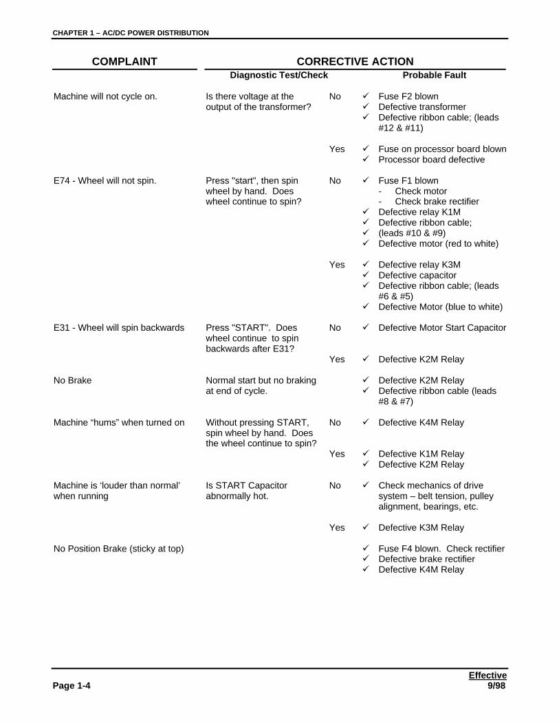
COMPLAINT CORRECTIVE ACTIONDiagnostic Test/Check Probable Fault
Machine will not cycle on. Is there voltage at theoutput of the transformer?
No ü Fuse F2 blownü Defective transformerü Defective ribbon cable; (leads
#12 & #11)
Yes ü Fuse on processor board blownü Processor board defective
E74 - Wheel will not spin. Press "start", then spinwheel by hand. Doeswheel continue to spin?
No ü Fuse F1 blown- Check motor- Check brake rectifier
ü Defective relay K1Mü Defective ribbon cable;ü (leads #10 & #9)ü Defective motor (red to white)
Yes ü Defective relay K3Mü Defective capacitorü Defective ribbon cable; (leads
#6 & #5)ü Defective Motor (blue to white)
E31 - Wheel will spin backwards Press "START". Doeswheel continue to spinbackwards after E31?
No ü Defective Motor Start Capacitor
Yes ü Defective K2M Relay
No Brake Normal start but no brakingat end of cycle.
ü Defective K2M Relayü Defective ribbon cable (leads
#8 & #7)
Machine “hums” when turned on Without pressing START,spin wheel by hand. Doesthe wheel continue to spin?
No ü Defective K4M Relay
Yes ü Defective K1M Relayü Defective K2M Relay
Machine is ‘louder than normal’when running
Is START Capacitorabnormally hot.
No ü Check mechanics of drivesystem – belt tension, pulleyalignment, bearings, etc.
Yes ü Defective K3M Relay
No Position Brake (sticky at top) ü Fuse F4 blown. Check rectifierü Defective brake rectifierü Defective K4M Relay

CHAPTER 1 – AC/DC POWER DISTRIBUTION
Effective9/98 Page 1-5
CHAPTER 1 – AC/DC POWER DISTRIBUTION
EffectivePage 1-6 9/98
Effective9/98 Page 2-1
CHAPTER 2THEORY OF OPERATION
EQUIPMENT OPERATION DESCRIPTION
GENERAL BALANCER INFORMATION
JBC 8.6 / 8.7 balancers are designed to statically or dynamically balance vehicle tires weighing a maximum of150 pounds. All operational controls are located on the front display panel. From this location, the customer canmanually input wheel dimensions, select balance type, and control operation of the unit.
The 8.6 balancer calculates the distance and diameter of wheels via inputs from the distance gauge. The 8.7balancer adds wheel width to the dimensions which may be measured automatically. The width gauge arm ismounted on a specially reinforced wheel guard, and measures wheel width electronically after the distance to therim has been calculated. Wheel width may be measured first on an 8.7 balancer, but the width dimension will notbe displayed until the distance to the wheel is input, via the distance gauge or manually.
A captured backing spring makes mounting wheels more convenient. Back coning is recommended wheneverpossible. A spacer is supplied to place between the backing spring housing and the back of the centering conewhen a cone fits deep in the center hole of a wheel. This helps ensure proper centering of the wheel on thecentering adapter. A cast steel Quick Nut with replaceable threaded jaws is used to secure the wheel in place. Aremovable clamping hood and protective cover contact the wheel and lock it in place without marring the surface.
All imbalance measurements are taken in one spin cycle. At the end of the cycle the wheel brakes to a stop andthe dynamic or static imbalance of the wheel is displayed. If the positioning brake is active, the wheel will rotateuntil the right plane counterbalance weight location is at the 12:00 position, then brake to a complete stop. Thepositioning brake may be turned on or off using setup code C11C. Default mode is brake ON.
Imbalances may be read in ounces or grams. The machine may be set up to read to the nearest 1 gram (0.05ounce), or to suppress small imbalances by using code C2C. Factory setting is suppression of imbalances lessthan 3.5 grams (1/8 ounce).
If errors occur during a balance cycle, an error message will appear. Balancer error messages are listed inAppendix A of this manual.
Operator calibration using code C14C will correct for small errors in measured imbalances. If an error (E15)occurs when performing C14C calibration, the customer may have not calibrated his machine for a very long time,and the correction required to ensure accuracy might be too great to be compensated with this procedure. Basiccalibration (C83C and C84C) will be required to correct this situation. E15 may also indicate that a weight may belodged between the Suspension weldment and the balancer skin, or that problems exist with the transducers orthe Interface PCB.
United States regulations require that all balancers be equipped with a wheel guard and electronic interlock. Thisis standard equipment on these balancers and must not be disabled. The units are set up so the machine maystart only with the hood closed. Raising the wheel guard interrupts power to the drive motor and prevents theshaft from spinning.
Complete Operation Instructions are located in Appendix D of this manual. Please refer to this manual for specificoperation instructions for these machines.
CHAPTER 2 – THEORY OF OPERATION
EffectivePage 2-2 9/98
OPERATING CYCLE DESCRIPTION
INITIAL TURN ON TESTS
When turned on, a momentary running display will flash and a self-test sequence begins. If any errors aredetected, the display will show an error code. Press STOP to advance the display through all error codesdetected. Following display of all error codes, the rest of the turn-on sequence will initiate. The balancer model(8.6 or 8.7) will display on the left side and the software version on the right. After displaying the machine andversion information, the initial parameters will be displayed (6” width, 14” diameter). These measurements willcontinue to display until actual wheel parameters are entered, or until five minutes of inactivity has passed. Afterapproximately five minutes of inactivity, the display automatically goes into a display scroll mode, sequentiallyilluminating every display segment one at a time until the operator inputs some information in the machine withkeypad, shaft, or hood.
The display scroll mode is controlled using the C15C code. To activate, enter c15c, then press . to changethe right hand display reading from 1 to 2 or 0. Press STOP to activate the new setting. At setting ‘1’, the displayscroll comes on after about five minutes of inactivity. Any movement of the parameter entry arms or shaft,lowering the hood, or any keyboard input returns the display to the ‘ready’ state. ‘1’ is the factory default setting.If . is pressed once while C15C is active, the right hand display will be set to ‘2’. Pressing the STOP key at thispoint locks the machine in the display scroll mode until STOP is pushed again or until the machine is turned OFFand ON. Setting the right display to ‘0’ and pressing STOP turns the scroll feature OFF. Again, turning themachine OFF and ON restores the setting to ‘1’.
CUSTOMER CALIBRATION, C14C
Customer calibration is designed to allow compensation of slight inaccuracies in the balancer without having toperform a complete Basic Calibration. If a balancer has not been calibrated for an extended period using C14C,the calibration attempt may fail because of extreme (30% or greater) changes in components. Failure because ofthis or several other problems may result in an E15 error. See Appendix A.
INDIVIDUAL COMPONENT OPERATION
Power (208 / 230 VAC, 60 Hz, 20A) connects at the OFF / ONswitch which serves as both the input block and the power switch.Power ground connects to the chassis at a unique location.
From the OFF / ON switch, power is routed to the Motor Control PCB. This multi-purpose board distributes orswitches power to all other sections of the balancer. Three 12-Ampere Fast Blow fuses protect Motor and Brakecircuits. A 0.4-Ampere quick blow fuse protects the transformer primary input and all components downstreamfrom the transformer such as the Interface, Processor, and Display PCBs.
The Motor Control PCB contains the Motor Start Capacitor, four relays (Capacitor input - K3M, Motor Control –(spin) K1M, Spin Brake - K2M, and Positioning Brake - K4M), a 230::21 Volt Transformer, a positioning brakediode, a ribbon cable to connect to downstream components, and a connection buss to route power in and out ofthe board.
The Interface PCB acts as a distribution hub for power and as a routing hub for signals. Power is supplied to theInterface PCB from the Motor Control PCB, then is distributed to the Processor PCB, the Encoder, the Distance,Diameter and Width Potentiometers, and Transducers. Signal inputs from the Encoder, the Transducers, and theDistance, Diameter, and Width Potentiometers are relayed through the Interface PCB to the Processor PCB.
Transducers are piezoelectric cells that create varying output voltages when an unbalanced rotating mass appliespressure variations to the cell. These outputs are routed through the Interface PCB to the Processor PCB. Theraw transducer inputs are used by the Processor PCB to calculate counterbalance weight amounts.
IMPORTANT
NEVER pair Power Ground with anyother grounds.
CHAPTER 2 - THEORY OF OPERATION
Effective9/98 Page 2-3
The encoder is a set of light emitting diodes and photocells that is attached to the Shaft Weldment next to thelarge pulley. Light from the LEDs shines through 64 slots in the steel encoder disk attached to the rotating largepulley. Two of the LEDs combine to manufacture a 256 count. This is done by detecting the leading and trailingedge of each of the two out-of-phase LED/slot pulses. A single longer slot provides a home reference pulse toallow counting the number of revolutions the shaft has turned, and to calculate the speed of the shaft in RPM.
Wheel size is determined electronically by inputs from the Distance, Diameter (8.6 balancers) and Widthpotentiometers (8.7 balancer). A constant five volts is applied to each of these potentiometers. Depending on theposition of the wiper on the pot, an output voltage of 0.12 to ≅ 5.00 volts is received at the Interface PCB. Theinitial position of the potentiometers is physically set so the output is slightly above zero (from 0.12 to 0.25 volts).Linear response is created by electronic calibration of the potentiometers so the response ramp measurescorrectly as the gauge arms are extended or rotated.
The Processor PCB takes inputs from all sections of the machine and determines if the inputs are valid. If theinputs are within acceptable parameters, an algorithm is applied to them, calculations are made, and imbalanceamount and position readings are displayed. If inputs lie outside acceptable parameters, error codes aregenerated and displayed.
The Display PCB takes output from the Processor PCB and displays it to the machine operator. This is the soleoutput, machine to operator. The keypad, and START and STOP buttons are sandwiched between the displaycover and the Display PCB. There is no physical connection between these keypads and the Display PCB underresting conditions.
The Keypad and START / STOP buttons provide direct input from the operator to the balancer. A conductive padon the back of each key closes contacts on the Display PCB when pressed, giving the operator direct commandover the machine.
Spin control of the balancer is initiated by pushing the START button or by lowering the hood if autospin isenabled. Autospin may be disabled or enabled by setting C13C to 0 or 1, respectively.
FUNCTION CODE SETTINGS
Function codes may be verified, or changed as follows:
SELECTING CODES
Enter a code by pressing C, the code number, then C again. The right display will show a numbercorresponding to the readiness condition of the machine with respect to the code. After verifying or changing thecode, press the STOP (red) button.
Unless stored in the computer memory a function code that has been changed returns to the original state whenthe power is turned OFF and back ON.
STORING CODES
To store code settings in the computer memory:Enter C10C. Then press keys 1 & 3 at the same time. The processor will beep once (indicating that 1 & 3were pressed simultaneously), then will beep three times, signalling the code setting has been stored in thememory.
FUNCTION CODES
C1C Readout resolution (round off) - Press the . (decimal) button to change.1 = 0.05 Ounce / 1 Gram
CHAPTER 2 – THEORY OF OPERATION
EffectivePage 2-4 9/98
0 = 0.25 Ounce / 5 Gram Factory setting = 0
C2C Readout suppression of small imbalances, as selected using C9 or C8.Press . to turn on or off.1 = On0 = Off Factory setting = 1
If the readout is set to read in ounces, see C9 for suppression value used.If the readout is set to read in grams, see C8 for suppression value used.
C3C Readout in ounces or grams - Press . to change.1 = Ounces0 = Grams Factory setting = 1
C4C Electronic compensation of the residual imbalance. Enter c4c, then press START to operate thebalancer through a cycle. Press the STOP button to continue. Zero Compensation cannot be storedin computer memory and is not retained when power is OFF. Electronic compensation is reset to 0when power is turned off.
1 = ON0 = OFF
C5C Machine brakes or coasts when the wheel guard is lifted. Press . to change.
1 = Brakes when lifted0 = Coasts when lifted Factory setting = 1
C8C Entry in grams - readout suppression of small imbalances. Factory setting = 3.5 grams. Allimbalances equal to or less than the selected amount will display as 0 grams. To enter a new valueenter C8C, key in the new value then press C.
C9C Selection and entry in ounces of the readout suppression of small imbalances. Factory setting = 0.25ounce. All imbalances equal to or less than the selected amount displays as 0.00 ounces. To enter anew value enter C9C, key in the new value then press C.
C10C Stores selected codes data and adjustments into memory.
Enter C10C then press buttons 1 & 3 at the same time.Listen for a three tone audible acknowledgement.
C11C Selects index (position) brake operation. Press the . button to turn on and off.
1 = Shaft stops at the wheel weight position as the tire is rotated.0 = Shaft does not stop at the wheel weight position
C12C Display of total number of balancing cycles on the unit. Entry of this code displays the total number ofmeasuring runs the balancer has run. Maximum count is 999,999. Machines should have less than100 (test spins) when shipped.Code C43C resets.
C13C Enables operation by pressing start button and / or lowering the wheel guard. Press . to change.
1 = Machine starts as the wheel guard is closed or when the start button is pushed.0 = Machine starts only when the start button is pushed.
CHAPTER 2 - THEORY OF OPERATION
Effective9/98 Page 2-5
C15C Enables display scroll feature. If machine is left idle for approximately 5 minutes the displayilluminates each LED individually, then flashes "JbC bAL", and repeats the process. Display scrollingstops when any key or gauge is operated, unless the code is set to ‘2’. Press . to change settingswhen C15C is active. Press STOP to exit C15C. Factory setting = 1. Turn-on default = 1.
0= off1= on after 5 minutes2= on immediately (resets to a value of 1 when STOP is pressed or machine is turned off).
C17C Selects the number of shaft revolutions necessary to complete a measuring run. Selectable from 5 to10 revolutions. If PRO-MATCH is being used, the number of measuring revolutions is automaticallyset to 10. Press . to change the setting, then key in the value desired. Factory setting is 10revolutions.
NOTE: the more revolutions used to complete the measuring cycle, the more accurate themachine will be.
C18C Fine adjustment of Rim Diameter - (see C19C for explanation of procedure)
C19C Fine adjustment of Rim Width.
C18C and C19C allow corrections of small wheel dimension errors when measuring wheelparameters using distance, diameter, and width parameter entry arms.
Mount and measure a wheel of known size and note which gauge is at error. Enter the required "C"code, and hold the appropriate gauge against the wheel at the measuring point. Key in the offsetrequired (in inches) to correct the reading. If the offset change must be negative, press the "S/D" keyafter entering the value. Press C key to accept the offset entered. The wheel dimension willimmediately be corrected to the actual value.
Press STOP to exit. Enter C10C then press buttons 1 & 3 at the same time. Listen for a threetone audible acknowledgement.
*C20C Electronic Angle adjustment for counterbalance location. This code is used to correct errors inlocating counterbalance weight position. The procedure is as follows:
Balance a wheel to zero (use C4C if necessary). Install a known weight and press START to runthe machine through a balancing cycle. When the wheel stops, check the weight location using thearrow indicators on the display panel. The imbalance should be at the 6:00 o'clock position.
If the imbalance is located at other than at 6 o’clock, enter C20C and adjust the position byentering a new value, and pressing C again.
When looking at the wheel from the end of the shaft toward the machine- entering a larger number moves the imbalance location clockwise.- entering a smaller number moves the imbalance counter-clockwise.
* C24C Selects if rim distance must be entered in millimeters (mm) or centimeters(cm) through the key panel. The machine is factory set for cm. To check forthe correct setting, Enter C24C
1= display for distance in cm0 = display for distance in mmIf 0 displays press . to change to 1. Press STOP.
NOTE
"C" codesmarked withan * can onlybe accessed
with theencoder
unplugged.
CHAPTER 2 – THEORY OF OPERATION
EffectivePage 2-6 9/98
* C43C Resets the cycle counter. A cycle counter built into the balancer software records each time thebalancer is operated. When C12C is entered, the total number of cycles on the machine isdisplayed.
C47C Sets the computer to operate as an 8.6 or 8.7 unit. Enter the code and the display will show eitherJBC 8.6, or JBC 8.7.
Press . to select the desired machine type.
Effective9/98 Page 3-1
CHAPTER 3INSTALLATION, CALIBRATION, MAINTENANCE
GENERAL
This chapter presents standard installation and check out procedures that must be done when installing an 8.6 or8.7 balancer. Although these machines have been set up at the factory and were compliant with manufacturingstandards when they were shipped, changes may occur during shipment that are beyond the control of themanufacturer or shipper. Following these procedures exactly will ensure that the balancer will perform asdesigned following installation.
INSTALLATION PROCEDURES
SELECTION OF MACHINE TYPE
Enter C47C. The display will show either JBC 8.6 or JBC 8.7. JBC 8.6 machines have automatic parameterentry for distance to the wheel and diameter of the wheel. JBC 8.7 balancers add automatic parameter entry forwheel width. Press the . button to change the display to the correct machine model being installed. PressSTOP to exit.
C codes controlling spin characteristics will set to normal factory settings. These C codes may be altered tochange the characteristics of the machine if necessary. A complete list of C codes and the machine functionsthey control is given in Chapter 2.
IMPORTANT!
DO NOT TURN OFF POWER WHILE MAKING ADJUSTMENTSAFTER COMPLETING THE FOLLOWING PROCEDURES THE DATA MUST BESTORED IN THE COMPUTER MEMORY SO THEY WILL BE RETAINED WHEN
POWER IS SWITCHED OFF.
DANGEROUSLY HIGH VOLTAGES EXISTWITHIN THESE MACHINES. USE THE‘ONE HAND RULE’ WHEN SERVICING!
!RISK OF ENTANGLEMENT KEEP YOURSELF,CLOTHING AND TEST EQUIPMENT CLEAR OF
MOVING PARTS! ENTANGLEMENT IN MOVING PARTSCAN CAUSE SEVERE INJURY.
!
CHAPTER 3 – INSTALLATION, CALIBRATION, AND MAINTENANCE
EffectivePage 3-2 9/98
RIM DISTANCE GAUGE ADJUSTMENT JBC 8.6 / 8.7 SERIES
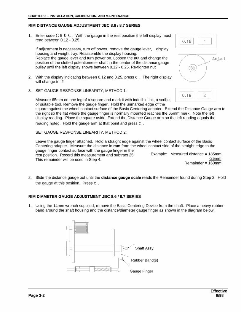
1. Enter code C80C. With the gauge in the rest position the left display mustread between 0.12 - 0.25
If adjustment is necessary, turn off power, remove the gauge lever, displayhousing and weight tray. Reassemble the display housing.Replace the gauge lever and turn power on. Loosen the nut and change theposition of the slotted potentiometer shaft in the center of the distance gaugepulley until the left display shows between 0.12 - 0.25. Re-tighten nut
2. With the display indicating between 0.12 and 0.25, press c. The right displaywill change to ‘2’.
3. SET GAUGE RESPONSE LINEARITY, METHOD 1:
Measure 65mm on one leg of a square and mark it with indelible ink, a scribe,or suitable tool. Remove the gauge finger. Hold the unmarked edge of thesquare against the wheel contact surface of the Basic Centering adapter. Extend the Distance Gauge arm tothe right so the flat where the gauge finger is normally mounted reaches the 65mm mark. Note the leftdisplay reading. Place the square aside. Extend the Distance Gauge arm so the left reading equals thereading noted. Hold the gauge arm at that point and press c.
SET GAUGE RESPONSE LINEARITY, METHOD 2:
Leave the gauge finger attached. Hold a straight edge against the wheel contact surface of the BasicCentering adapter. Measure the distance in mm from the wheel contact side of the straight edge to thegauge finger contact surface with the gauge finger in therest position. Record this measurement and subtract 25.This remainder will be used in Step 4.
2. Slide the distance gauge out until the distance gauge scale reads the Remainder found during Step 3. Holdthe gauge at this position. Press c.
RIM DIAMETER GAUGE ADJUSTMENT JBC 8.6 / 8.7 SERIES
1. Using the 14mm wrench supplied, remove the Basic Centering Device from the shaft. Place a heavy rubberband around the shaft housing and the distance/diameter gauge finger as shown in the diagram below.
Example: Measured distance = 185mm-25mm
Remainder = 160mm
Shaft Assy.
Rubber Band(s)
Gauge Finger
CHAPTER 3 – INSTALLATION, CALIBRATION, AND MAINTENANCE
Effective9/98 PAGE 3-3
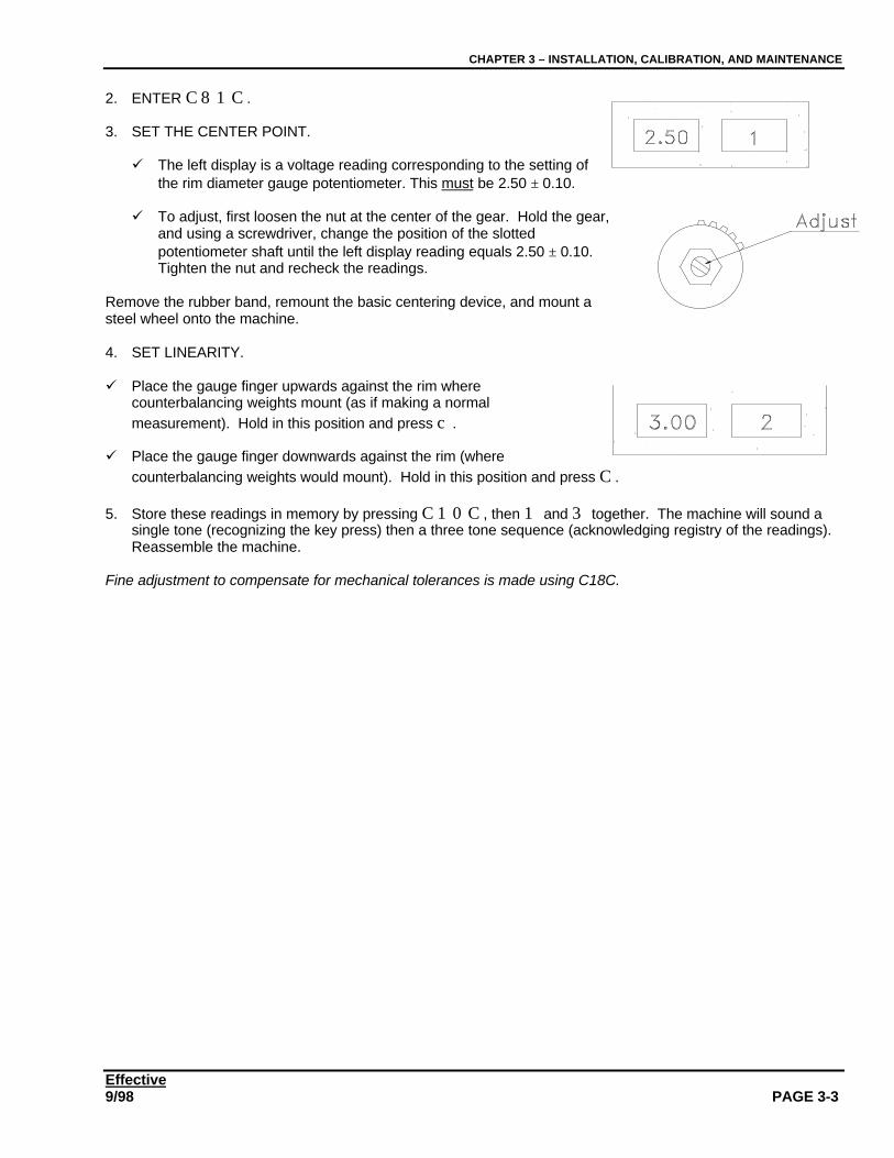
2. ENTER C81C.
3. SET THE CENTER POINT.
ü The left display is a voltage reading corresponding to the setting ofthe rim diameter gauge potentiometer. This must be 2.50 ± 0.10.
ü To adjust, first loosen the nut at the center of the gear. Hold the gear,and using a screwdriver, change the position of the slottedpotentiometer shaft until the left display reading equals 2.50 ± 0.10.Tighten the nut and recheck the readings.
Remove the rubber band, remount the basic centering device, and mount asteel wheel onto the machine.
4. SET LINEARITY.
ü Place the gauge finger upwards against the rim wherecounterbalancing weights mount (as if making a normalmeasurement). Hold in this position and press c.
ü Place the gauge finger downwards against the rim (wherecounterbalancing weights would mount). Hold in this position and press C.
5. Store these readings in memory by pressing C10C, then 1 and 3 together. The machine will sound asingle tone (recognizing the key press) then a three tone sequence (acknowledging registry of the readings).Reassemble the machine.
Fine adjustment to compensate for mechanical tolerances is made using C18C.
CHAPTER 3 – INSTALLATION, CALIBRATION, AND MAINTENANCE
EffectivePage 3-4 9/98
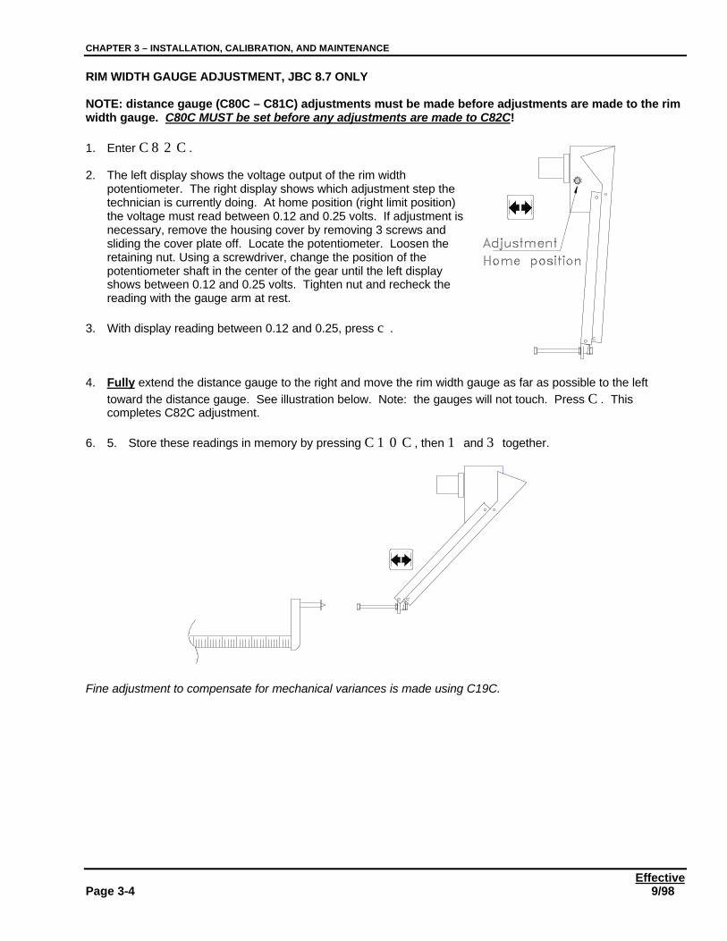
RIM WIDTH GAUGE ADJUSTMENT, JBC 8.7 ONLY
NOTE: distance gauge (C80C – C81C) adjustments must be made before adjustments are made to the rimwidth gauge. C80C MUST be set before any adjustments are made to C82C!
1. Enter C82C.
2. The left display shows the voltage output of the rim widthpotentiometer. The right display shows which adjustment step thetechnician is currently doing. At home position (right limit position)the voltage must read between 0.12 and 0.25 volts. If adjustment isnecessary, remove the housing cover by removing 3 screws andsliding the cover plate off. Locate the potentiometer. Loosen theretaining nut. Using a screwdriver, change the position of thepotentiometer shaft in the center of the gear until the left displayshows between 0.12 and 0.25 volts. Tighten nut and recheck thereading with the gauge arm at rest.
3. With display reading between 0.12 and 0.25, press c.
4. Fully extend the distance gauge to the right and move the rim width gauge as far as possible to the lefttoward the distance gauge. See illustration below. Note: the gauges will not touch. Press C. Thiscompletes C82C adjustment.
6. 5. Store these readings in memory by pressing C10C, then 1 and 3 together.
Fine adjustment to compensate for mechanical variances is made using C19C.
CHAPTER 3 – INSTALLATION, CALIBRATION, AND MAINTENANCE
Effective9/98 PAGE 3-5
C18C / C19C FINE ADJUSTMENT OF RIM DIAMETER AND RIM WIDTH GAUGES - JBC 8.6 & 8.7
C18C – Makes electronic corrections of wheel rim diameter measurements.C19C – Makes electronic corrections of wheel rim width measurements.
Procedures for both codes are similar. An explanation of the process follows.
1. Mount a wheel on the machine.
2. Enter C18C then press the diameter button, for diameter corrections.or
Enter C19C then press the width button, for rim width corrections.
3. Measure wheel with an appropriate gauge, or take the dimensions from the wheel itself. Hold the distance /diameter gauge against the wheel. The actual measured value to the nearest 0.1” is displayed in the lefthand display.
4. Enter the difference between the actual rim dimension and the value in the left hand display by typing in thechange required to make the reading correct in inches (max. 9.9"). If the measured value needs to bedecreased, enter the value then press the static / dynamic button to change the sign (a minus sign will appearin front of the entered value). The value entered will be displayed in the right hand display.
5. After correction(s) have been entered, press C to accept. The correction entered will immediately be addedto or subtracted from the reading in the left-hand display.
6. Press STOP to clear the C code. Store these readings in memory by pressing C10C, then 1 and 3together.
7. Check to see verify that the gauges measure the wheel correctly.
See example on the following page.Example: Corrections for a width gauge, which gives a 4.5” measurement 4.5" on a 6" rim.
Enter C19C. Hold the gauge against rim. The left hand display will show 4.5. To adjust, enter the differencebetween the actual rim width (6.0”) and the measured width (4.5”) in the left hand display. In this example, thedifference is 6” - 4.5” = 1.5”. Press 1.5 then press C (1.5 will appear in the right hand display). The value inthe left-hand display is now 6.0. Press STOP. This change must be stored in the permanent memory usingC10C. Measure a rim to see if gauges measure correctly.
Notes:1. All gauges must be calibrated using C80C, C81C and C82C codes as before.2. Any offsets entered using C18C or C19C may be nullified by enteringü C18C, then pressing the rim diameter button.ü C19C, then pressing the rim width button.3. Any code may be cancelled by pressing the STOP button.4. If power is cycled OFF and ON before storing results with C10C, NO CHANGES WILL BE MADE TO THE
WAY THE BALANCER READS OR CALCULATES!
CHAPTER 3 – INSTALLATION, CALIBRATION, AND MAINTENANCE
EffectivePage 3-6 9/98
READOUT ADJUSTMENT (BASIC CALIBRATION)
Basic calibration is done at the factory. However, it is recommended that the basic calibration and shaft zeroingbe done at the customer’s location after the machine has been physically installed and following completion ofC80C, C81C, and C82C (8.7 balancers). Repeating basic calibration at the customer’s location assures precisionaccuracy and will result in a high degree of customer satisfaction with the balancer performance.
1. Mount a wheel (steel wheel preferred). Enter rim width, distance and diameter.
2. Balance the wheel to less than 1.0 ounce imbalance in each plane.
3. Select a test weight between 3 and 4 ounces. NOTE: the test weight used should be weighed on a gramsscale to the nearest 0.1 grams (if less than 100 grams) or the nearest 1.0 grams (weights 100 grams orlarger). Weights may be weighed at a College, High School, or Junior High School Physics, Chemistry, orGeneral Science lab. Technicians should select four or five weights in good condition weighing between 3.25and 3.5 ounces, paint the weights a distinctive color such as red or yellow, then call a local school and weighthe weights to determine their exact weight. Write the actual weight of each weight on the item with anindelible marker. Weights will vary as much as 7 to 10 grams from the indicated weight amount.
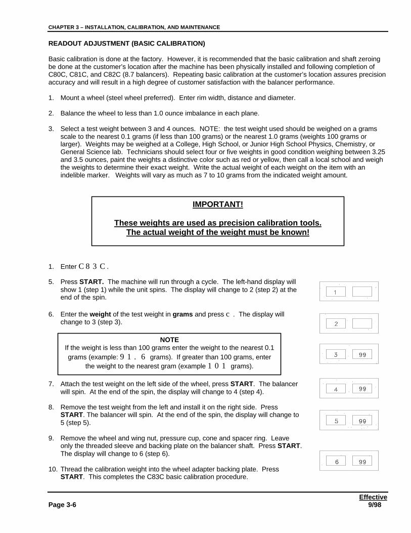
1. Enter C83C.
5. Press START. The machine will run through a cycle. The left-hand display willshow 1 (step 1) while the unit spins. The display will change to 2 (step 2) at theend of the spin.
6. Enter the weight of the test weight in grams and press c. The display willchange to 3 (step 3).
7. Attach the test weight on the left side of the wheel, press START. The balancerwill spin. At the end of the spin, the display will change to 4 (step 4).
8. Remove the test weight from the left and install it on the right side. PressSTART. The balancer will spin. At the end of the spin, the display will change to5 (step 5).
9. Remove the wheel and wing nut, pressure cup, cone and spacer ring. Leaveonly the threaded sleeve and backing plate on the balancer shaft. Press START.The display will change to 6 (step 6).
10. Thread the calibration weight into the wheel adapter backing plate. PressSTART. This completes the C83C basic calibration procedure.
IMPORTANT!
These weights are used as precision calibration tools.The actual weight of the weight must be known!
NOTEIf the weight is less than 100 grams enter the weight to the nearest 0.1grams (example: 91.6 grams). If greater than 100 grams, enter
the weight to the nearest gram (example 101 grams).
CHAPTER 3 – INSTALLATION, CALIBRATION, AND MAINTENANCE
Effective9/98 PAGE 3-7
Doing Basic Calibration erases any value which may have been stored in memory to compensate for shaftimbalance. Following completion of C83C, the shaft must be balanced using C84C.
SHAFT BALANCE PROCEDURE
1. Remove the wheel and wheel adapter including the cones, threaded sleeve and adapter backing plate.
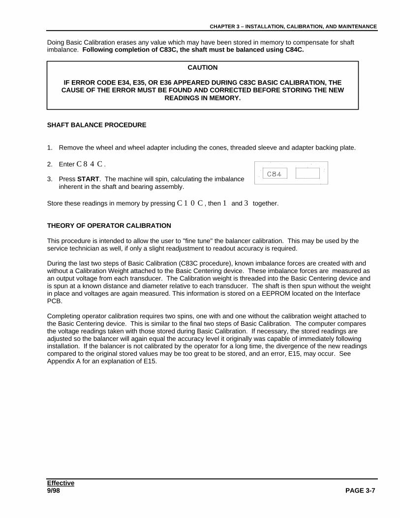
2. Enter C84C.
3. Press START. The machine will spin, calculating the imbalanceinherent in the shaft and bearing assembly.
Store these readings in memory by pressing C10C, then 1 and 3 together.
THEORY OF OPERATOR CALIBRATION
This procedure is intended to allow the user to "fine tune" the balancer calibration. This may be used by theservice technician as well, if only a slight readjustment to readout accuracy is required.
During the last two steps of Basic Calibration (C83C procedure), known imbalance forces are created with andwithout a Calibration Weight attached to the Basic Centering device. These imbalance forces are measured asan output voltage from each transducer. The Calibration weight is threaded into the Basic Centering device andis spun at a known distance and diameter relative to each transducer. The shaft is then spun without the weightin place and voltages are again measured. This information is stored on a EEPROM located on the InterfacePCB.
Completing operator calibration requires two spins, one with and one without the calibration weight attached tothe Basic Centering device. This is similar to the final two steps of Basic Calibration. The computer comparesthe voltage readings taken with those stored during Basic Calibration. If necessary, the stored readings areadjusted so the balancer will again equal the accuracy level it originally was capable of immediately followinginstallation. If the balancer is not calibrated by the operator for a long time, the divergence of the new readingscompared to the original stored values may be too great to be stored, and an error, E15, may occur. SeeAppendix A for an explanation of E15.
CAUTION
IF ERROR CODE E34, E35, OR E36 APPEARED DURING C83C BASIC CALIBRATION, THECAUSE OF THE ERROR MUST BE FOUND AND CORRECTED BEFORE STORING THE NEW
READINGS IN MEMORY.
CHAPTER 3 – INSTALLATION, CALIBRATION, AND MAINTENANCE
EffectivePage 3-8 9/98
OPERATOR CALIBRATION PROCEDURE
1. Without a wheel on the balancer remove cones, spacers, wingnut, and pressure cup from the adapter. Leaveonly the threaded shaft and faceplate attached to the balancer shaft. The Calibration Weight is threaded intothe left rear wall of the balancer chassis.
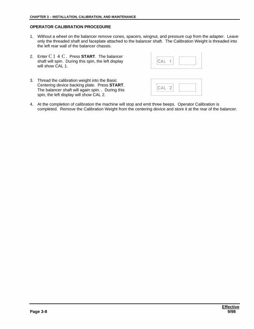
2. Enter C14C. Press START. The balancershaft will spin. During this spin, the left displaywill show CAL 1.
3. Thread the calibration weight into the BasicCentering device backing plate. Press START.The balancer shaft will again spin. . During thisspin, the left display will show CAL 2.
4. At the completion of calibration the machine will stop and emit three beeps. Operator Calibration iscompleted. Remove the Calibration Weight from the centering device and store it at the rear of the balancer.
Effective7/99 Page 4-1
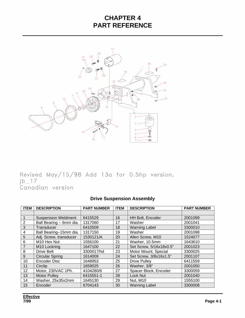
CHAPTER 4PART REFERENCE
Drive Suspension Assembly
ITEM DESCRIPTION PART NUMBER ITEM DESCRIPTION PART NUMBER
1 Suspension Weldment 6415529 16 HH Bolt, Encoder 20010992 Ball Bearing – 6mm dia. 1317060 17 Washer 20010413 Transducer 6410509 18 Warning Label 33000104 Ball Bearing–15mm dia. 1317150 19 Washer 20010985 Adj. Screw, transducer 1530121/A 20 Allen Screw, M10 15240776 M10 Hex Nut 1556100 21 Washer, 10.5mm 16436107 M10 Lockring 1647100 22 Set Screw, 5/16x18x0.5” 20010238 Drive Belt 3300017/hd 23 Motor Mount, Special 33000259 Circular Spring 1614009 24 Set Screw, 3/8x16x1.5” 200110710 Encoder Disc 1648953 25 Drive Pulley 641155911 Circlip 1659025 26 Washer, 3/8” 200105012 Motor, 230VAC 1Ph. 4104280/6 27 Spacer Block, Encoder 330005913 Motor Pulley 6415551-1 28 Lock Nut 200104014 Washer, 25x35x2mm 1645130 29 Nut, M10 155510015 Encoder 6704143 30 Warning Label 3300008
CHAPTER 4 - PARTS
EffectivePage 4-2 7/99
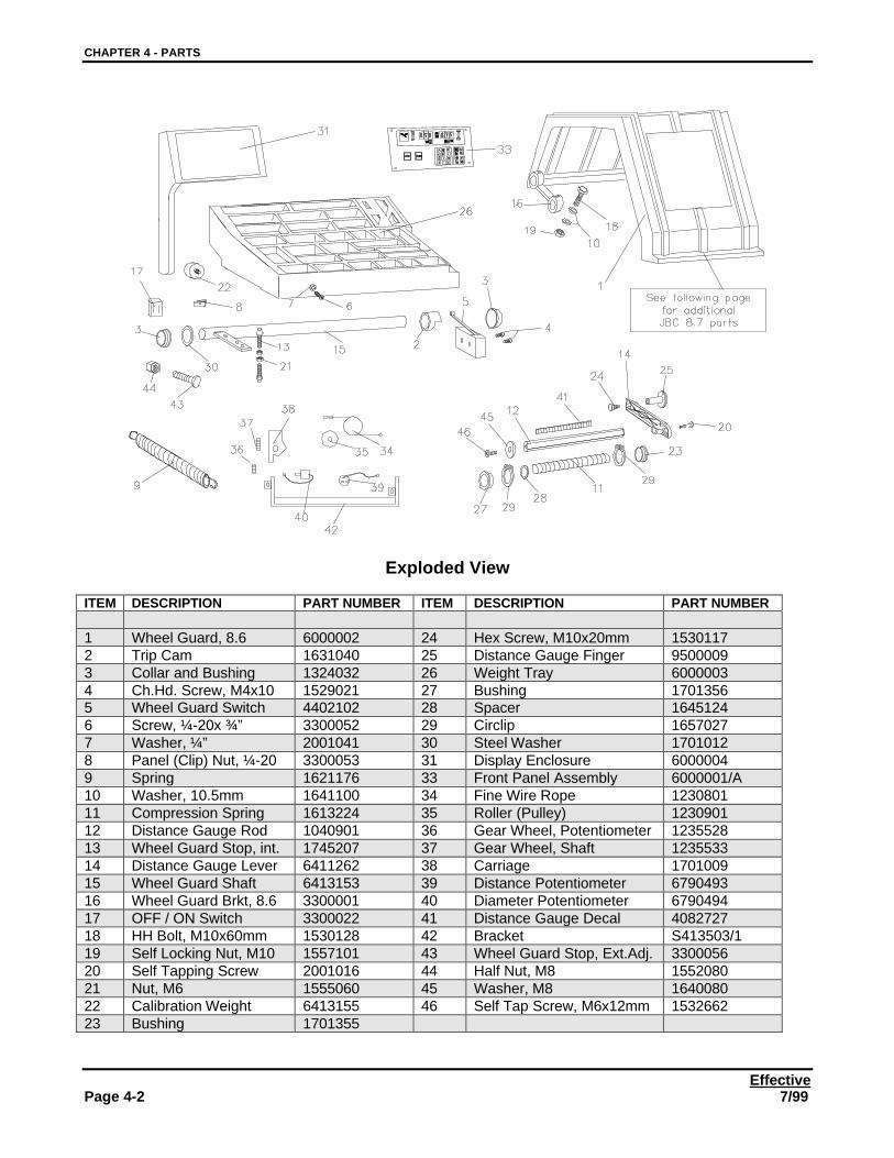
Exploded View
ITEM DESCRIPTION PART NUMBER ITEM DESCRIPTION PART NUMBER
1 Wheel Guard, 8.6 6000002 24 Hex Screw, M10x20mm 15301172 Trip Cam 1631040 25 Distance Gauge Finger 95000093 Collar and Bushing 1324032 26 Weight Tray 60000034 Ch.Hd. Screw, M4x10 1529021 27 Bushing 17013565 Wheel Guard Switch 4402102 28 Spacer 16451246 Screw, ¼-20x ¾” 3300052 29 Circlip 16570277 Washer, ¼” 2001041 30 Steel Washer 17010128 Panel (Clip) Nut, ¼-20 3300053 31 Display Enclosure 60000049 Spring 1621176 33 Front Panel Assembly 6000001/A10 Washer, 10.5mm 1641100 34 Fine Wire Rope 123080111 Compression Spring 1613224 35 Roller (Pulley) 123090112 Distance Gauge Rod 1040901 36 Gear Wheel, Potentiometer 123552813 Wheel Guard Stop, int. 1745207 37 Gear Wheel, Shaft 123553314 Distance Gauge Lever 6411262 38 Carriage 170100915 Wheel Guard Shaft 6413153 39 Distance Potentiometer 679049316 Wheel Guard Brkt, 8.6 3300001 40 Diameter Potentiometer 679049417 OFF / ON Switch 3300022 41 Distance Gauge Decal 408272718 HH Bolt, M10x60mm 1530128 42 Bracket S413503/119 Self Locking Nut, M10 1557101 43 Wheel Guard Stop, Ext.Adj. 330005620 Self Tapping Screw 2001016 44 Half Nut, M8 155208021 Nut, M6 1555060 45 Washer, M8 164008022 Calibration Weight 6413155 46 Self Tap Screw, M6x12mm 153266223 Bushing 1701355
CHAPTER 4 - PARTS
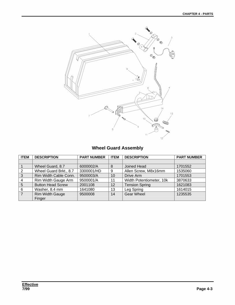
Effective7/99 Page 4-3
Wheel Guard Assembly
ITEM DESCRIPTION PART NUMBER ITEM DESCRIPTION PART NUMBER
1 Wheel Guard, 8.7 6000002/A 8 Joined Head 17015522 Wheel Guard Brkt., 8.7 3300001/HD 9 Allen Screw, M8x16mm 15350603 Rim Width Cable Conn. 9500003/A 10 Drive Arm 17015534 Rim Width Gauge Arm 9500001/A 11 Width Potentiometer, 10k 38706335 Button Head Screw 2001108 12 Tension Spring 16210836 Washer, 8.4 mm 1641080 13 Leg Spring 16140157 Rim Width Gauge
Finger9500008 14 Gear Wheel 1235535
CHAPTER 4 - PARTS
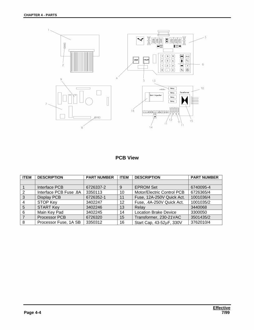
EffectivePage 4-4 7/99
PCB View
ITEM DESCRIPTION PART NUMBER ITEM DESCRIPTION PART NUMBER
1 Interface PCB 6726337-2 9 EPROM Set 6740095-42 Interface PCB Fuse .8A 3350113 10 Motor/Electric Control PCB 6726365/43 Display PCB 6726352-1 11 Fuse, 12A-250V Quick Act. 1001036/44 STOP Key 3402247 12 Fuse, .4A-250V Quick Act. 1001035/25 START Key 3402246 13 Relay 34400686 Main Key Pad 3402245 14 Location Brake Device 33000507 Processor PCB 6726320 15 Transformer, 230-21VAC 3501435/28 Processor Fuse, 1A SB 3350312 16 Start Cap, 43-52µF, 330V 3762010/4
CHAPTER 4 - PARTS
Effective7/99 Page 4-5
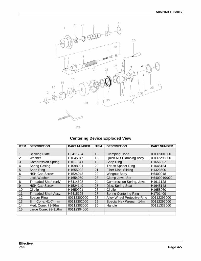
Centering Device Exploded View
ITEM DESCRIPTION PART NUMBER ITEM DESCRIPTION PART NUMBER
1 Backing Plate H6411234 16 Clamping Hood 001123010002 Washer H1645047 18 Quick-Nut Clamping Assy. 001122980003 Compression Spring H1611341 19 Snap Ring H16560524 Spring Casing H1098001 20 Thrust Spacer Ring H16451545 Snap Ring H1655092 21 Fiber Disc, Sliding H13236006 HSH Cap Screw H1524043 22 Wingnut Body H64090187 Lock Washer H1654060 23 Clamp Jaws, Set H6409019/0208 Threaded Shaft (only) H6414698 24 Compression Spring, Jaws H16111289 HSH Cap Screw H1524149 25 Disc, Spring Seat H164514810 Circlip H1659901 26 Circlip H165806011 Threaded Shaft Assy. H6415195 27 Spring Centering Ring H170140912 Spacer Ring 00112300000 28 Alloy Wheel Protective Ring 0011229600013 Sm. Cone, 41-74mm 00112302000 29 Special Hex Wrench, 14mm 0011229700014 Med. Cone, 71-96mm 00112303000 30 Handle 0011133300015 Large Cone, 93-116mm 00112304000
CHAPTER 4 - PARTS
EffectivePage 4-6 7/99
PARTS IN ALPHABETICAL ORDER
DESCRIPTION PART NUMBER COMMENTSAdj. Screw, transducer 1530121/AAllen Screw, M10 1524077Allen Screw, M8x16mm 1535060Alloy Wheel Protective Ring 112296Ball Bearing – 6mm dia. 1317060Ball Bearing–15mm dia. 1317150Bracket S413503/1Bushing 1701355Bushing 1701356Button Head Screw 2001108Calibration Weight 6413155Carriage 1701009Ch.Hd. Screw, M4x10 1529021Circlip 1659025Circlip 1657027Circlip 1658060Circular Spring 1614009Clamp Jaws, Set 6409019/020Clamping Hood 112301Collar and Bushing 1324032Compression Spring 1613224Compression Spring, Jaws 1611128Diameter Potentiometer 6790494Disc, Spring Seat 1645148Display Enclosure 6000004Display PCB 6726352-1Distance Gauge Decal 4082727Distance Gauge Finger 9500009Distance Gauge Lever 6411262Distance Gauge Rod 1040901Distance Potentiometer 6790493Drive Arm 1701553Drive Belt 3300017/hdDrive Pulley 6411559Encoder 6704143Encoder Disc 1648953EPROM Set 6740095-4EPROM Set 6740095-4Fiber Disc, Sliding 1323600Fine Wire Rope 1230801Front Panel Assembly 6000001/AFuse, .4A-250V Quick Act. 1001035/2Fuse, .4A-250V Quick Act. 1001035/2Fuse, 12A-250V Quick Act. 1001036/4Fuse, 12A-250V Quick Act. 1001036/4Gear Wheel 1235535Gear Wheel, Potentiometer 1235528Gear Wheel, Shaft 1235533Half Nut, M8 1552080Handle 112312Hex Screw, M10x20mm 1530117HH Bolt, Encoder 2001099HH Bolt, M10x60mm 1530128Interface PCB 6726337-2
CHAPTER 4 - PARTS
Effective7/99 Page 4-7
DESCRIPTION PART NUMBER COMMENTSInterface PCB Fuse .8A 3350113Joined Head 1701552Leg Spring 1614015Location Brake Device 3300050Location Brake Device 3300050Lock Nut 2001040M10 Hex Nut 1556100M10 Lockring 1647100Main Key Pad 3402245Motor Mount, Special 3300025Motor Pulley 6415551-1Motor, 230VAC 1Ph. 4104280/6Motor/Electric Control PCB 6726365/4Motor/Electric Control PCB 6726365/4Nut, M10 1555100Nut, M6 1555060OFF / ON Switch 3300022Panel (Clip) Nut, ¼-20 3300053Processor Fuse, 1A SB 3350312Processor PCB 6726320Quick-Nut Clamping Assy. 112298Relay 3440068Relay 3440068Rim Width Cable Conn. 9500003/ARim Width Gauge Arm 9500001/ARim Width Gauge Finger 9500008Roller (Pulley) 1230901Screw, ¼-20x ¾” 3300052Self Locking Nut, M10 1557101Self Tap Screw, M6x12mm 1532662Self Tapping Screw 2001016Set Screw, 3/8x16x1.5” 2001107Set Screw, 5/16x18x0.5” 2001023Snap Ring 1656052Spacer 1645124Spacer Block, Encoder 3300059Special Hex Wrench, 14mm 112297Spring 1621176Spring Centering Ring 1701409Start Cap, 43-52µF, 330V 3762010/4Start Cap, 43-52µF, 330V 3762010/4START Key 3402246Steel Washer 1701012STOP Key 3402247Suspension Weldment 6415529Tension Spring 1621083Thrust Spacer Ring 1645154Transducer 6410509Transformer, 230-21VAC 3501435/2Transformer, 230-21VAC 3501435/2
Trip Cam 1631040Warning Label 3300010Warning Label 3300008Washer 2001041Washer 2001098Washer, ¼” 2001041
CHAPTER 4 - PARTS
EffectivePage 4-8 7/99
DESCRIPTION PART NUMBER COMMENTSWasher, 10.5mm 1643610Washer, 10.5mm 1641100Washer, 25x35x2mm 1645130Washer, 3/8” 2001050Washer, 8.4 mm 1641080Washer, M8 1640080Weight Tray 6000003Wheel Guard Brkt, 8.6 3300001Wheel Guard Brkt., 8.7 3300001/HDWheel Guard Shaft 6413153Wheel Guard Stop, Ext.Adj. 3300056Wheel Guard Stop, int. 1745207Wheel Guard Switch 4402102Wheel Guard, 8.6 6000002Wheel Guard, 8.7 6000002/AWidth Potentiometer, 10k 3870633Wingnut Body 6409018
CHAPTER 4 - PARTS
Effective7/99 Page 4-9
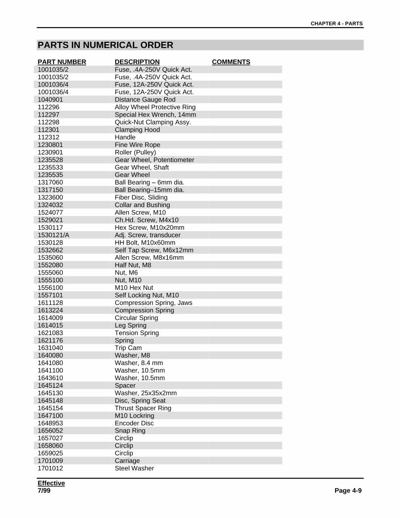
PARTS IN NUMERICAL ORDER
PART NUMBER DESCRIPTION COMMENTS1001035/2 Fuse, .4A-250V Quick Act.1001035/2 Fuse, .4A-250V Quick Act.1001036/4 Fuse, 12A-250V Quick Act.1001036/4 Fuse, 12A-250V Quick Act.1040901 Distance Gauge Rod112296 Alloy Wheel Protective Ring112297 Special Hex Wrench, 14mm112298 Quick-Nut Clamping Assy.112301 Clamping Hood112312 Handle1230801 Fine Wire Rope1230901 Roller (Pulley)1235528 Gear Wheel, Potentiometer1235533 Gear Wheel, Shaft1235535 Gear Wheel1317060 Ball Bearing – 6mm dia.1317150 Ball Bearing–15mm dia.1323600 Fiber Disc, Sliding1324032 Collar and Bushing1524077 Allen Screw, M101529021 Ch.Hd. Screw, M4x101530117 Hex Screw, M10x20mm1530121/A Adj. Screw, transducer1530128 HH Bolt, M10x60mm1532662 Self Tap Screw, M6x12mm1535060 Allen Screw, M8x16mm1552080 Half Nut, M81555060 Nut, M61555100 Nut, M101556100 M10 Hex Nut1557101 Self Locking Nut, M101611128 Compression Spring, Jaws1613224 Compression Spring1614009 Circular Spring1614015 Leg Spring1621083 Tension Spring1621176 Spring1631040 Trip Cam1640080 Washer, M81641080 Washer, 8.4 mm1641100 Washer, 10.5mm1643610 Washer, 10.5mm1645124 Spacer1645130 Washer, 25x35x2mm1645148 Disc, Spring Seat1645154 Thrust Spacer Ring1647100 M10 Lockring1648953 Encoder Disc1656052 Snap Ring1657027 Circlip1658060 Circlip1659025 Circlip1701009 Carriage1701012 Steel Washer
CHAPTER 4 - PARTS
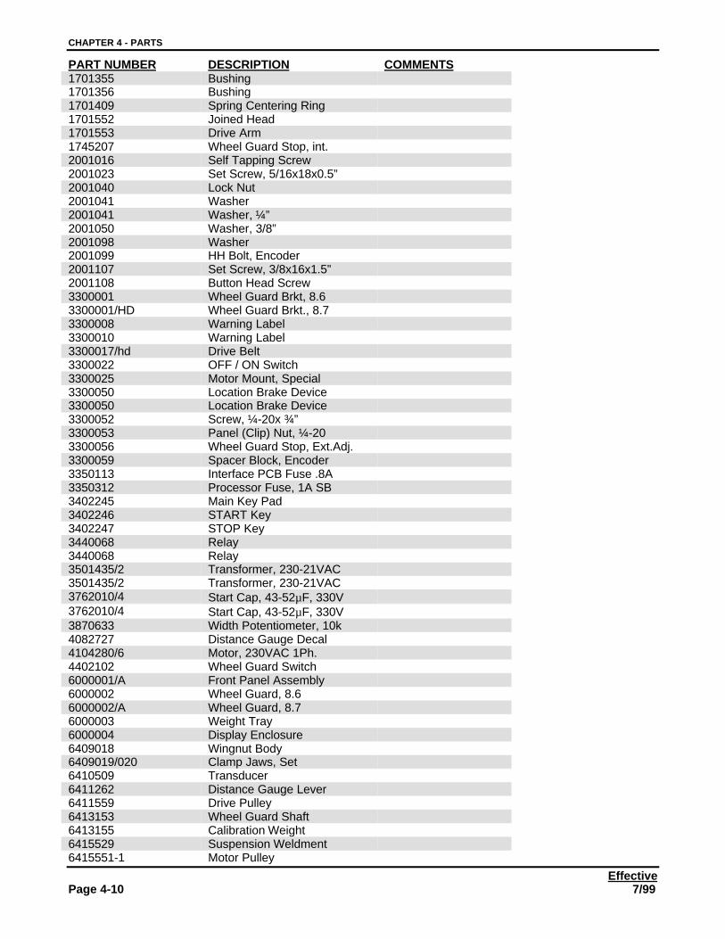
EffectivePage 4-10 7/99
PART NUMBER DESCRIPTION COMMENTS1701355 Bushing1701356 Bushing1701409 Spring Centering Ring1701552 Joined Head1701553 Drive Arm1745207 Wheel Guard Stop, int.2001016 Self Tapping Screw2001023 Set Screw, 5/16x18x0.5”2001040 Lock Nut2001041 Washer2001041 Washer, ¼”2001050 Washer, 3/8”2001098 Washer2001099 HH Bolt, Encoder2001107 Set Screw, 3/8x16x1.5”2001108 Button Head Screw3300001 Wheel Guard Brkt, 8.63300001/HD Wheel Guard Brkt., 8.73300008 Warning Label3300010 Warning Label3300017/hd Drive Belt3300022 OFF / ON Switch3300025 Motor Mount, Special3300050 Location Brake Device3300050 Location Brake Device3300052 Screw, ¼-20x ¾”3300053 Panel (Clip) Nut, ¼-203300056 Wheel Guard Stop, Ext.Adj.3300059 Spacer Block, Encoder3350113 Interface PCB Fuse .8A3350312 Processor Fuse, 1A SB3402245 Main Key Pad3402246 START Key3402247 STOP Key3440068 Relay3440068 Relay3501435/2 Transformer, 230-21VAC3501435/2 Transformer, 230-21VAC3762010/4 Start Cap, 43-52µF, 330V3762010/4 Start Cap, 43-52µF, 330V3870633 Width Potentiometer, 10k4082727 Distance Gauge Decal4104280/6 Motor, 230VAC 1Ph.4402102 Wheel Guard Switch6000001/A Front Panel Assembly6000002 Wheel Guard, 8.66000002/A Wheel Guard, 8.76000003 Weight Tray6000004 Display Enclosure6409018 Wingnut Body6409019/020 Clamp Jaws, Set6410509 Transducer6411262 Distance Gauge Lever6411559 Drive Pulley6413153 Wheel Guard Shaft6413155 Calibration Weight6415529 Suspension Weldment6415551-1 Motor Pulley
CHAPTER 4 - PARTS
Effective7/99 Page 4-11
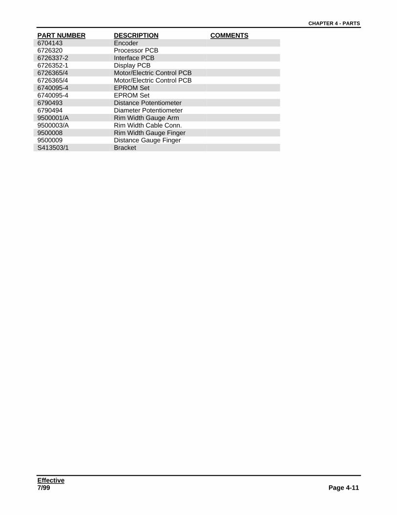
PART NUMBER DESCRIPTION COMMENTS6704143 Encoder6726320 Processor PCB6726337-2 Interface PCB6726352-1 Display PCB6726365/4 Motor/Electric Control PCB6726365/4 Motor/Electric Control PCB6740095-4 EPROM Set6740095-4 EPROM Set6790493 Distance Potentiometer6790494 Diameter Potentiometer9500001/A Rim Width Gauge Arm9500003/A Rim Width Cable Conn.9500008 Rim Width Gauge Finger9500009 Distance Gauge FingerS413503/1 Bracket
CHAPTER 4 - PARTS
EffectivePage 4-12 7/99
Effective9/98 Page 5-1
CHAPTER 5ACCURACY TESTS, DIAGNOSTIC FUNCTION CODES, AND
TEST PROCEDURES,
ACCURACY TESTS
SHAFT IMBALANCE, WHEEL ADAPTER TO SHAFT REMOUNT TEST
This test proves the wheel balancer centering device is balanced and turns true, and proves thecentering device inside taper and balancer shaft outside taper (mating surfaces) are true.
1. Verify that electronic compensation for shaft imbalance is OFF. This may be checked by entering codeC4C. The display must show 0. If 1 appears in the right display window, switch the balancer off and thenback on after a few seconds. The default turn-on state for the balancer is 0 for C4C.
2. Mount a medium size wheel assembly (14”), input the rim dimensions, and balance the wheel assembly to0.00 ounces imbalance in both planes. This must be balanced to exactly 0.00 in both planes with the smallimbalance suppression (C2C) turned off.
3. Spin the balancer several times. Verify that no more than 0.05 oz. imbalance is displayed.
4. Loosen the Allen bolt located in the center of the threaded shaft. Do NOT remove the wheel assembly.
5. Rotate the centering adapter with the balanced wheel still attached 180° on the balancer shaft. Tighten thesocket hex head bolt securely .
6. Operate the balancer. The new imbalance displayed should not exceed 0.25 oz.
If the test produces reading out of tolerance:
1. Remove the complete wheel adapter and operate the balancer. The display should indicate zero. If not,balance the shaft using Code C84C - see Adjustment Procedures. This sets shaft imbalance to zero.
2. Remove the wheel adapter and check the tapered surfaces of the basic centering device and balancer shaft.They should be clean and smooth. Clean and retest. If the test still produces unacceptable results:
A. Run the above test using a known good wheel adapter. If this test produces the same results, go to B. Ifthe problem is resolved, replace the threaded sleeve portion of the wheel adapter.
B. Using a dial indicator, measure runout of the balancer shaft tapered mounting surface. Acceptabletolerance is 0.0015" T.I.R. (Total Indicated Runout). If the surface measures out of tolerance, replace thebalancer shaft.
CHAPTER 5 – ACCURACY TESTS, DIAGNOSTICS FUNCTION CODES, AND TEST PROCEDURES
EffectivePage 5-2 9/98
WHEEL ADAPTER COMPONENTS - CENTER CONE ADAPTER REMOUNT TEST.
1. Verify that the results of the SHAFT IMBALANCE, WHEEL ADAPTER TO SHAFT REMOUNT TEST (Page5-1) are acceptable.
2. Verify that electronic compensation for shaft imbalance is OFF. Check by entering C4C. The display mustread 0. If 1 appears switch the balancer off and then back on after a few seconds. (Alternative: switch thebalancer OFF and ON to set to default values.)
3. Balance a 30 to 40 lb. wheel to exactly 0.00 ounces imbalance in each plane. Small imbalance suppression(C2C) must be turned off.
4. Spin the balancer several times. Verify that no more than 0.05 oz. imbalance is displayed.
5. Loosen the wingnut, hold the centering cone in place and rotate wheel 180 degree. Tighten the wingnut.
6. Operate the balancer through a cycle. The new display is the remount error. A reading no greater than 0.50ounces is considered acceptable.
If the readings are not acceptable:
1. Is the wheel known to be true? (See the Note above.) Substitute a known good wheel and retest.
2. Are the mating surfaces of the basic centering adapter backing plate and the threaded shaft clean andsmooth? Are the bolts tight?
3. Is there noticeable play between the center cone and threaded shaft? Try using another cone in the set. Runthe same test, but rotate the cone only 180 degrees.
4. Measure radial runout of the threaded shaft at the point where the threads end. Acceptable tolerance forT.I.R. is 0.00l5". Replace the threaded shaft if tolerance exceeds this level.
5. Using a dial indicator, measure the lateral runout of the basic centering device faceplate while rotating theshaft 360°. Acceptable tolerance is 0.00l5".
6. Substitute known good basic centering device components individually to isolate the cause of the remounterror.
IMPORTANT: READ BEFORE PERFORMING REMOUNT TESTS
The test will check the wheel and the basic centering device. Most wheels are manufactured to far lessexacting tolerances than the basic centering device. The majority of the measured remount error is usuallycaused by the wheel - not the basic centering device. It is best to use a wheel that is known to be true.The wheel must have a round smooth center hole and the surface that presses against the wheel adapterbacking plate must be flat and smooth. Because remount error is a function of mechanical tolerances theheavier the wheel assembly the larger the mounting error. Use a mid size 14" or 15" wheel and tire -about 30 to 40 pounds. Usually OEM alloy wheels give the least wheel-induced error and the best remounttest results.
CHAPTER 5 – ACCURACY TESTS, DIAGNOSTICS FUNCTION CODES, AND TEST PROCEDURES
Effective9/98 Page 5-3
TESTING BALANCER READOUT ACCURACY - WEIGHT AMOUNT AND LOCATION
C4CC4C Used to check the imbalance read-out accuracy, and to insure that the sizes and locations ofcounterbalance weights called for are correct.
1. Mount a wheel assembly, enter rim dimensions, and balance the wheel within 1 ounce on each plane. EnterC4C. The right display will show 0,, and the left should show C4. Press START.
2. The balancer will run through a cycle, stop and display 1 in the right display. This indicates that the out ofbalance condition of the mounted wheel has been measured by the computer. This measured imbalance willbe subtracted from subsequent measurement runs. This test wheel imbalance will remain stored in memoryuntil the machine is switched OFF or until C4C is selected and the 1 is changed to 0 by pressing ..
3. Press STOP to exit, then run the wheel through a cycle by pressing START.
4. Press and hold the STOP button. The right and left display will both show 0.00. Release the STOP button.
5. Using a Known Test Weight (this weight has to have been weighed to the nearest 0.1 gram if less than 100grams in weight, the nearest 1.0 gram if 100 grams or more). It is very important to be sure what the actualweight amount is for this test.
6. Attach the weight to the right plane of the wheel. Operate the balancer.
7. When the balancer stops press and hold in the STOP button. A weight reading corresponding to the testweight should be displayed on the right. Allowable tolerance for this test is ±0.15 ounces. Maximumallowable weight reading displayed on the left is 0.15 ounces. Release the STOP (red) button. See theexample below:
TO END THE TEST PRESS C4C , THE . KEY, & STOP.
Example
Select a 3 ounce test weight. Verify the exact weight amount using scales. The display for the plane withthe weight attached must show between 2.85 and 3.15 ounces, while the opposite side must show no morethan 0.15 ounces.
Position the test weight at exactly 6 o'clock. The center bar of the right location display should be illuminated.Allowable tolerance is ± one bar from center. If weight location is out of tolerance see Note (B).
Remove the test weight from the right side of the wheel, attach it to the left and spin the wheel again. Seeabove for tolerances.
Troubleshooting
ü Check the rim distance gauge setting using adjustment code C80C. Adjust the gauge per the C80Cprocedure.
ü If only the location accuracy is out of tolerance, the wheel may have slipped on the balancer shaft duringbraking. It is possible that a problem may exist with a transducer or encoder. If these two componentsare suspected, substitution with known good parts is the only reliable method of troubleshooting.
CHAPTER 5 – ACCURACY TESTS, DIAGNOSTICS FUNCTION CODES, AND TEST PROCEDURES
EffectivePage 5-4 9/98
DIAGNOSIS AND TEST CODE LIST
C50C Rim distance potentiometer JBC 8.6 / 8.7
C51C Rim diameter potentiometer JBC 8.6 / 8.7
C52C Rim width potentiometer JBC 8.7 only
C53C Display test
C54C Encoder test
C55C Unregulated D.C. voltage at Processor circuit board
C59C Value of the shaft imbalance compensation stored in Memory
C60C Shaft RPM
C61C Reference imbalance Value determined during last C83C adjustment
C62C Imbalance location displayed in degrees
C63C Continuous high-resolution imbalance measurement averaged and displayed each 40 revolutions.
C64C Pick-up sensitivity
C65C Pick-up phase difference in percent
C66C Virtual suspension weldment system dimensions determined during last C83C adjustment
C68C Number of revolutions required before reaching measuring speed
C69C Automatic testing measurement cycle intervals
C74C Position disc. Encoder test. Also, see C54C.
C75C Transducer / encoder test
CHAPTER 5 – ACCURACY TESTS, DIAGNOSTICS FUNCTION CODES, AND TEST PROCEDURES
Effective9/98 Page 5-5
EXPLANATION OF DIAGNOSTICS CODES
C50C This code is used to check the rim distance gauge potentiometer on JBC 8.6 / 8.7 balancers.
Enter C50C A voltage reading corresponding to the position of the gauge is shown in the left display. Ameasurement in millimeters (mm) corresponding to the position of the gauge is shown in the right display. Withthe gauge lever retracted into the weight tray a voltage reading of between 0.12-0.25 should be displayed. As thelever is extended, the voltage reading should increase smoothly and in proportion to the distance moved up to amaximum of approximately 5.00 volts. Be sure that the voltage does not increase or decrease erratically.
**********TO END TEST PRESS THE STOP BUTTON**********
C51C Use this code to check the rim diameter gauge potentiometer on JBC 8.6 / 8.7 balancers.
Enter C51C. A voltage reading corresponding to the position of the gauge is shown in the left display.A measurement in millimeters (mm) corresponding to the position of the gauge is shown in the right display. Asthe gauge lever is rotated 360 degrees the voltage should change evenly through a range of 0 volts to 5.00 volts.
**********TO END TEST PRESS THE STOP BUTTON**********
C52C Use this code to check the rim width potentiometer on JBC 8.7 balancers only.
Enter C52C. A voltage reading corresponding to the position of the gauge is shown in the left display.A measurement in millimeters (mm) corresponding to the position of the gauge is shown in the right display. Withthe gauge lever in the rest position, a voltage of between 0.12-0.25 should be displayed. As the lever is movedtowards the machine (to the left) the voltage should increase proportional to the distance moved up to a maximumof approximately 5.00 volts. The voltage must not increase or decrease erratically.
C53C Used to check the display circuit board LEDs.
Enter C53C All LED segments will light. If one or more segments are defective, an error message, E60,should be displayed when the machine is switched on. To correct, replace the Display PCB.
**********TO END TEST PRESS THE STOP KEY**********
Notes for codes C50C, C51C and C52C
A voltage which is out of tolerance with the gauge retracted indicates that the gauge needs to beadjusted using C80C, C81C, or C82C adjustment codes.
A voltage which does not change or changes erratically indicates a defective potentiometer or amechanical problem such as a loose potentiometer shaft, or loose or broken wire, etc.
CHAPTER 5 – ACCURACY TESTS, DIAGNOSTICS FUNCTION CODES, AND TEST PROCEDURES
EffectivePage 5-6 9/98
C54C Used to check the Encoder. The complete test consists of four sections and is done with the motorturning the shaft. Test code C74C is a companion code to C54C.
Enter C54C - Press start.
ü This is the A channel test. 1 will show in the left display. The right display will show a number which mayfluctuate ± two numbers. This number should range from 40 - 60.
ü Press the . button. 2 will show in the left display. This is the B channel test. The right display will show anumber which may fluctuate ± two numbers. This number should be within the range of 40 - 60.
ü Press the . button. 3 will show in the left display. This is the zero reference test. The right display will show anumber which may fluctuate ± two numbers. This number should be within the range of 40 - 60.
ü Press the . button. 4 will show in the left display. The right display will show a number which may fluctuate ±two numbers. This number should be within the range of 20 -35.
Each test may be monitored repeatedly by pressing the . key.
If any of these tests display readings outside the specified range, the Encoder may require replacing.Replace the Encoder only if an out-of-tolerance reading is found in conjunction with machine malfunction. Do notreplace the encoder if C54C yields readings only slightly out of tolerance.
*************TO END THE TEST PRESS THE STOP BUTTON**************
C55C Used to check for proper D.C. voltage on the Processor PCB. A function of the Processor PCB is toprovide a DC power supply. 230 volts AC is supplied to the transformer primary. The transformer reduces thevoltage at the secondary to approx. 18-27 volts AC. This secondary voltage is converted by the power supply onthe processor PCB to filtered and regulated DC voltage. The DC voltage is used to operate the electronic circuitsand motor control relays.
Enter C55C The right display indicates the DC voltage. The allowable tolerance is 17 to 36 VDC.
If error E54 is displayed when the machine is turned on, less than 17 VDC will be measured.
If error E55 displayed this voltage will measure more than 36 VDC, SWITCH THE POWER OFF! Disconnect theProcessor circuit board ribbon connector for further troubleshooting.
To trouble-shoot check the voltage at the wall receptacle, the input voltage to the balancer at the transformerprimary, and the output voltage from the secondary.
*************TO END THE TEST PRESS THE STOP BUTTON**************
C59C Use this code to display the shaft imbalance compensation value stored in memory. This value is determined during the Shaft Balance procedure (C84C).
Enter C59C The displayed value is the shaft compensation in kg mm. This is a stored, static value.
*************TO END THE TEST PRESS THE STOP BUTTON**************
C60C Use this code to measure the speed of the balancing shaft. The Processor PCB counts pulsesreceived from the Encoder.
Enter C60C Press start. RPM is displayed. Balancing speed is 264-276 RPM (nominal).
*************TO END THE TEST PRESS THE STOP BUTTON**************
CHAPTER 5 – ACCURACY TESTS, DIAGNOSTICS FUNCTION CODES, AND TEST PROCEDURES
Effective9/98 Page 5-7
C63C Use this code to set the machine in continuous display mode. As the shaft turns, the display will blinkand update average imbalances every 40 revolutions. This is helpful when trouble shooting a intermittent orerratic reading problems
Enter C63C Press start.
*************TO END THE TEST PRESS THE STOP BUTTON***************
C65C Used to check phase difference between transducers. For the computer to correctly calculate thecounterbalance weights needed, the output voltages from the Transducers must be in phase.
Error message E34 will display during Code C83C adjustment if the Pick-ups are out of phase by more than 3degrees.
Enter C65C - The phase difference will display.
*************TO END THE TEST PRESS THE STOP BUTTON**************
C68C Used to check operation of the starting system.
Enter C68C. The left display shows the number of shaft revolutions required to reach measurement speedduring the last measurement.
The right display shows the number of shaft revolutions required to reach the speed where the motor startcapacitor switching relay dropped out during the last measurement cycle.
*************TO END THE TEST PRESS THE STOP BUTTON**************
C69C Use this code to set up the automatic measurement cycle. This cycle can be used to allow anunattended machine to measure, brake to a stop, sit at rest, then measure, brake to a stopcontinuously. Rest intervals can be selected. This code is helpful while troubleshooting intermittentproblems.
Enter C69C. The left display will show 1. This is rest interval one. The right display will show 50.This is the preset rest interval in seconds. To change the interval, key in a new interval in seconds and press theC key. The left display will show 2. This is preset rest interval two. The right display will show 170. To changethe interval, key in a new interval in seconds. Press the start button. The machine will cycle continuously.
*************END THE TEST PRESS THE STOP BUTTON**************
C74C Use this code as a quick check of the Encoder without the shaft turning under power. For a complete Encoder test, use code C54C.
Enter C74C. The left display will show C74. The right display will show a number from 0 to 255. Rotate theshaft and the numbers will change, counting in ascending order as the shaft is turned clockwise (descending asthe shaft is turned counter-clockwise). The count should reset to zero when the long slot (home reference) of theencoder disk passes the encoder optics. If the display is incorrect, the encoder should be replaced.
*************END THE TEST PRESS THE STOP BUTTON**************
CHAPTER 5 – ACCURACY TESTS, DIAGNOSTICS FUNCTION CODES, AND TEST PROCEDURES
EffectivePage 5-8 9/98
C75C - 5 Use this code to check Transducers. Transducers are mounted in the Support weldment of themachine. They are made of a material generates voltage proportional to the force applied against them. This testapplies exactly 2.5 volts to each Transducer. The test measures voltage drop across the Transducers.
Enter C75C then press 5. The left and right displays will both show a voltage. This is a reference voltage,(≈2.50 v), less the voltage drop. The left display shows the left Transducer reference voltage and the right displayshows the right Transducer reference voltage. Acceptable tolerance is 2.45 to 2.55 volts. Voltages below 2.20will display an error message during self test the machine is turned on. Transducers may be checked further bypressing down on the balancer shaft while watching the display. The voltages shown should vary above andbelow the nominal 2.50 volts.
This test proves if Transducers are shorted, open or disconnected from the Interface PCB. A successful test alsoproves that the output voltage path from the transducers through the Interface to the Processor PCB is correct.The test does not prove that the Transducers are producing the proper output voltage, that they are in phase, orthat they are properly installed. Further troubleshooting should be done using a known good part.
***********TO END THIS TEST PRESS THE STOP BUTTON TWICE***************
C75C - 6 Used to test the encoder, when an E73 error appears.
Enter C75C, then press 6. The left display will show the voltage supplied to the LEDs. A properlyfunctioning encoder will show approximately 1.20 volts. If the display shows 0.00 volts, unplug encoder. If thevoltage changes to 5.00 volts, the encoder is defective. If the voltage does not change, the Interface or ProcessorPCB is defective. If the display shows 5.00 volts with the encoder plugged in, use a screw driver to short acrossthe two M3 screws on the encoder. If the voltage drops to 0.00 volts, the encoder is defective. If voltage doesnot drop, the encoder cable is damaged, or the Interface or Processor PCB is defective.
PARTS REPLACEMENT - WHEN IS READJUSTMENT OR RECALIBRATION NECESSARY?
Some components can be replaced without resetting the function codes or readjusting the machine. Thefollowing items are exceptions:
Processor PCBInterface PCBTransducersMachine shaft, bearings or drive componentsRim Width potentiometerRim Diameter potentiometerRim Distance potentiometer
When replacing parts, always follow adjustment procedures as outlined in this manual. Use code C10C to storedata for the new parts in the computer memory.
NoteVoltage readings below 2.45 are suspect especially when erratic or intermittent measurement
problems have been noticed or error codes have appeared, such as: E34, E35, E36 duringAdjustment procedures or E76, E77, E78, E79 during Operators Calibration.
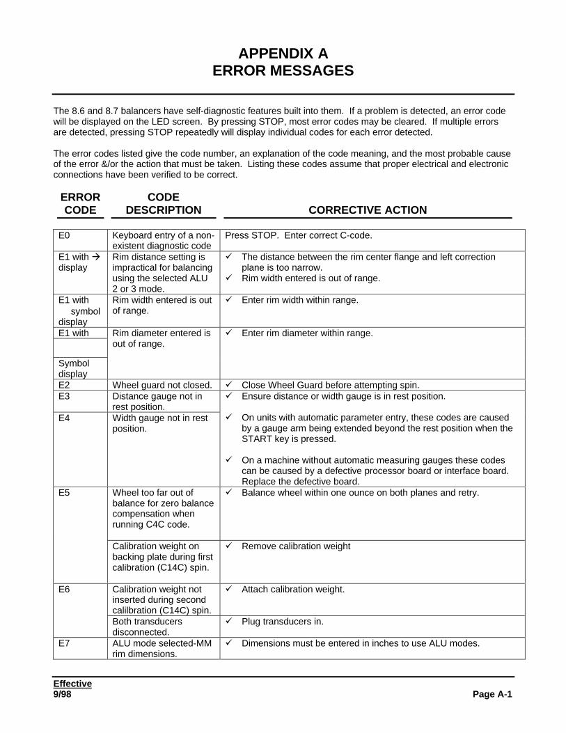
Effective9/98 Page A-1
APPENDIX AERROR MESSAGES
The 8.6 and 8.7 balancers have self-diagnostic features built into them. If a problem is detected, an error codewill be displayed on the LED screen. By pressing STOP, most error codes may be cleared. If multiple errorsare detected, pressing STOP repeatedly will display individual codes for each error detected.
The error codes listed give the code number, an explanation of the code meaning, and the most probable causeof the error &/or the action that must be taken. Listing these codes assume that proper electrical and electronicconnections have been verified to be correct.
ERRORCODE
CODEDESCRIPTION CORRECTIVE ACTION
E0 Keyboard entry of a non-existent diagnostic code
Press STOP. Enter correct C-code.
E1 with àdisplay
Rim distance setting isimpractical for balancingusing the selected ALU2 or 3 mode.
ü The distance between the rim center flange and left correctionplane is too narrow.
ü Rim width entered is out of range.
E1 with⇔ symboldisplay
Rim width entered is outof range.
ü Enter rim width within range.
E1 with
⇔
Symboldisplay
Rim diameter entered isout of range.
ü Enter rim diameter within range.
E2 Wheel guard not closed. ü Close Wheel Guard before attempting spin.E3 Distance gauge not in
rest position.E4 Width gauge not in rest
position.
ü Ensure distance or width gauge is in rest position.
ü On units with automatic parameter entry, these codes are causedby a gauge arm being extended beyond the rest position when theSTART key is pressed.
ü On a machine without automatic measuring gauges these codescan be caused by a defective processor board or interface board.Replace the defective board.
Wheel too far out ofbalance for zero balancecompensation whenrunning C4C code.
ü Balance wheel within one ounce on both planes and retry.E5
Calibration weight onbacking plate during firstcalibration (C14C) spin.
ü Remove calibration weight
Calibration weight notinserted during secondcalilbration (C14C) spin.
ü Attach calibration weight.E6
Both transducersdisconnected.
ü Plug transducers in.
E7 ALU mode selected-MMrim dimensions.
ü Dimensions must be entered in inches to use ALU modes.
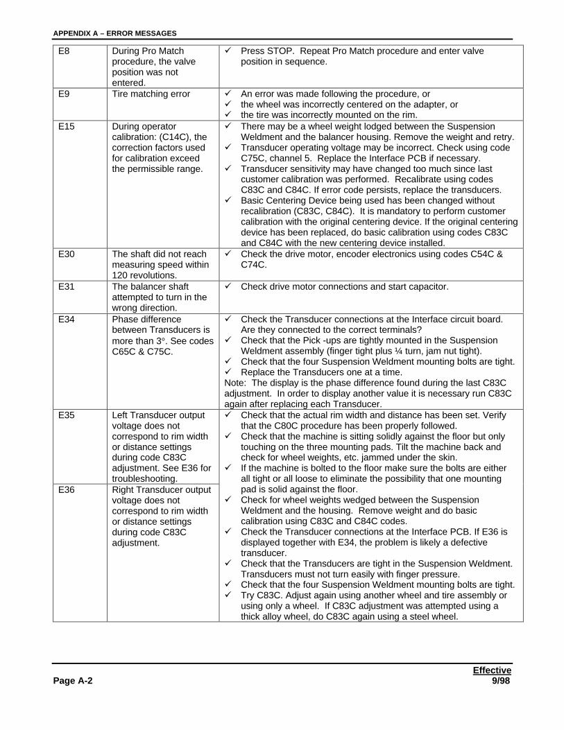
APPENDIX A – ERROR MESSAGES
EffectivePage A-2 9/98
E8 During Pro Matchprocedure, the valveposition was notentered.
ü Press STOP. Repeat Pro Match procedure and enter valveposition in sequence.
E9 Tire matching error ü An error was made following the procedure, orü the wheel was incorrectly centered on the adapter, orü the tire was incorrectly mounted on the rim.
E15 During operatorcalibration: (C14C), thecorrection factors usedfor calibration exceedthe permissible range.
ü There may be a wheel weight lodged between the SuspensionWeldment and the balancer housing. Remove the weight and retry.
ü Transducer operating voltage may be incorrect. Check using codeC75C, channel 5. Replace the Interface PCB if necessary.
ü Transducer sensitivity may have changed too much since lastcustomer calibration was performed. Recalibrate using codesC83C and C84C. If error code persists, replace the transducers.
ü Basic Centering Device being used has been changed withoutrecalibration (C83C, C84C). It is mandatory to perform customercalibration with the original centering device. If the original centeringdevice has been replaced, do basic calibration using codes C83Cand C84C with the new centering device installed.
E30 The shaft did not reachmeasuring speed within120 revolutions.
ü Check the drive motor, encoder electronics using codes C54C &C74C.
E31 The balancer shaftattempted to turn in thewrong direction.
ü Check drive motor connections and start capacitor.
E34 Phase differencebetween Transducers ismore than 3°. See codesC65C & C75C.
ü Check the Transducer connections at the Interface circuit board.Are they connected to the correct terminals?
ü Check that the Pick -ups are tightly mounted in the SuspensionWeldment assembly (finger tight plus ¼ turn, jam nut tight).
ü Check that the four Suspension Weldment mounting bolts are tight.ü Replace the Transducers one at a time.Note: The display is the phase difference found during the last C83Cadjustment. In order to display another value it is necessary run C83Cagain after replacing each Transducer.
E35 Left Transducer outputvoltage does notcorrespond to rim widthor distance settingsduring code C83Cadjustment. See E36 fortroubleshooting.
E36 Right Transducer outputvoltage does notcorrespond to rim widthor distance settingsduring code C83Cadjustment.
ü Check that the actual rim width and distance has been set. Verifythat the C80C procedure has been properly followed.
ü Check that the machine is sitting solidly against the floor but onlytouching on the three mounting pads. Tilt the machine back andcheck for wheel weights, etc. jammed under the skin.
ü If the machine is bolted to the floor make sure the bolts are eitherall tight or all loose to eliminate the possibility that one mountingpad is solid against the floor.
ü Check for wheel weights wedged between the SuspensionWeldment and the housing. Remove weight and do basiccalibration using C83C and C84C codes.
ü Check the Transducer connections at the Interface PCB. If E36 isdisplayed together with E34, the problem is likely a defectivetransducer.
ü Check that the Transducers are tight in the Suspension Weldment.Transducers must not turn easily with finger pressure.
ü Check that the four Suspension Weldment mounting bolts are tight.ü Try C83C. Adjust again using another wheel and tire assembly or
using only a wheel. If C83C adjustment was attempted using athick alloy wheel, do C83C again using a steel wheel.
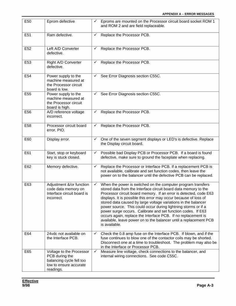
APPENDIX A – ERROR MESSAGES
Effective9/98 Page A-3
E50 Eprom defective ü Eproms are mounted on the Processor circuit board socket ROM 1and ROM 2 and are field replaceable.
E51 Ram defective. ü Replace the Processor PCB.
E52 Left A/D Converterdefective.
ü Replace the Processor PCB.
E53 Right A/D Converterdefective.
ü Replace the Processor PCB.
E54 Power supply to themachine measured atthe Processor circuitboard is low.
ü See Error Diagnosis section C55C.
E55 Power supply to themachine measured atthe Processor circuitboard is high.
ü See Error Diagnosis section C55C.
E56 A/D reference voltageincorrect.
ü Replace the Processor PCB.
E58 Processor circuit boarderror, PIO.
ü Replace the Processor PCB.
E60 Display error. ü One of the seven segment displays or LED's is defective. Replacethe Display circuit board.
E61 Start, stop or keyboardkey is stuck closed.
ü Possible bad Display PCB or Processor PCB. If a board is founddefective, make sure to ground the faceplate when replacing.
E62 Memory defective. ü Replace the Processor or Interface PCB. If a replacement PCB isnot available, calibrate and set function codes, then leave thepower on to the balancer until the defective PCB can be replaced.
E63 Adjustment &/or functioncode data memory onInterface circuit board isincorrect.
ü When the power is switched on the computer program transfersstored data from the Interface circuit board data memory to theProcessor circuit board memory. If an error is detected, code E63displays. It is possible this error may occur because of loss ofstored data caused by large voltage variations in the balancerpower source. This could occur during lightning storms or if apower surge occurs. Calibrate and set function codes. If E63occurs again, replace the Interface PCB. If no replacement isavailable, leave power on to the balancer until a replacement PCBis available.
E64 24vdc not available onthe Interface PCB.
ü Check the 0.8 amp fuse on the Interface PCB. If blown, and if thefuse continues to blow one of the contactor coils may be shorted.Disconnect one at a time to troubleshoot. The problem may also bein the Interface or Processor PCB.
E65 Voltage to the ProcessorPCB during thebalancing cycle fell toolow to ensure accuratereadings.
ü Measure line voltage, check connections to the balancer, andinternal wiring connections. See code C55C.
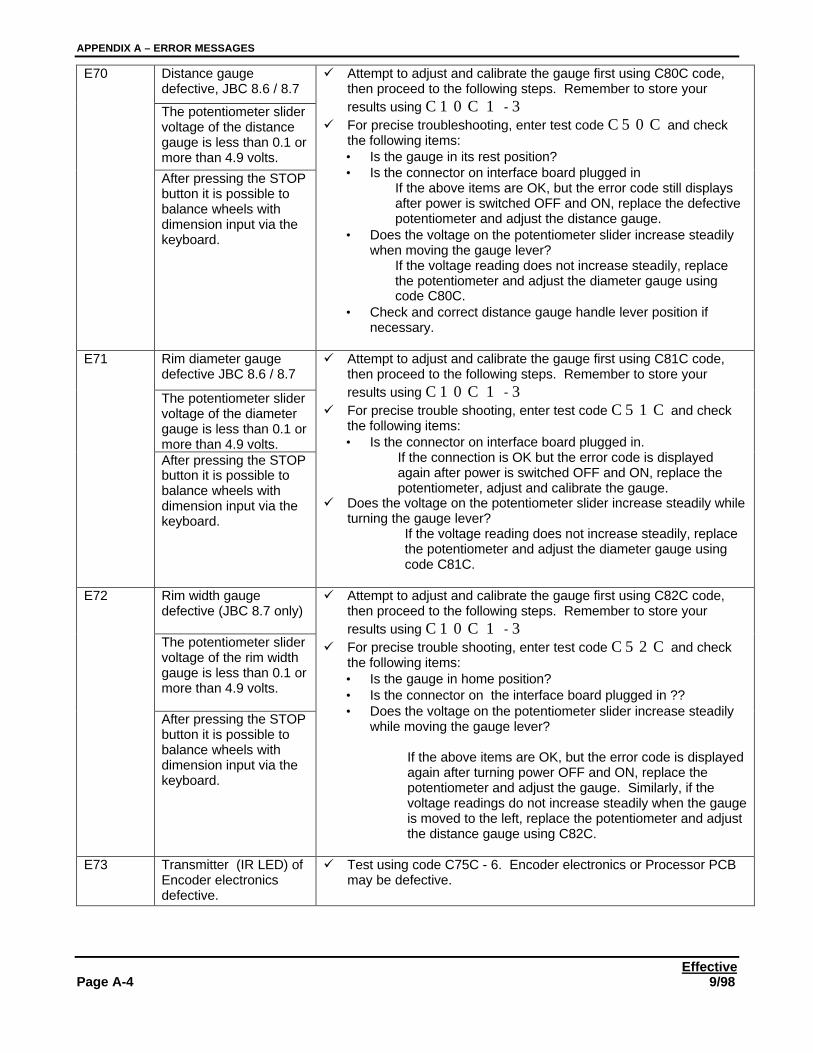
APPENDIX A – ERROR MESSAGES
EffectivePage A-4 9/98
Distance gaugedefective, JBC 8.6 / 8.7
The potentiometer slidervoltage of the distancegauge is less than 0.1 ormore than 4.9 volts.
E70
After pressing the STOPbutton it is possible tobalance wheels withdimension input via thekeyboard.
ü Attempt to adjust and calibrate the gauge first using C80C code,then proceed to the following steps. Remember to store yourresults using C10C 1 - 3
ü For precise troubleshooting, enter test code C50C and checkthe following items:• Is the gauge in its rest position?• Is the connector on interface board plugged in
If the above items are OK, but the error code still displaysafter power is switched OFF and ON, replace the defectivepotentiometer and adjust the distance gauge.
• Does the voltage on the potentiometer slider increase steadilywhen moving the gauge lever?
If the voltage reading does not increase steadily, replacethe potentiometer and adjust the diameter gauge usingcode C80C.
• Check and correct distance gauge handle lever position ifnecessary.
Rim diameter gaugedefective JBC 8.6 / 8.7
The potentiometer slidervoltage of the diametergauge is less than 0.1 ormore than 4.9 volts.
E71
After pressing the STOPbutton it is possible tobalance wheels withdimension input via thekeyboard.
ü Attempt to adjust and calibrate the gauge first using C81C code,then proceed to the following steps. Remember to store yourresults using C10C 1 - 3
ü For precise trouble shooting, enter test code C51C and checkthe following items:• Is the connector on interface board plugged in.
If the connection is OK but the error code is displayedagain after power is switched OFF and ON, replace thepotentiometer, adjust and calibrate the gauge.
ü Does the voltage on the potentiometer slider increase steadily whileturning the gauge lever?
If the voltage reading does not increase steadily, replacethe potentiometer and adjust the diameter gauge usingcode C81C.
Rim width gaugedefective (JBC 8.7 only)
The potentiometer slidervoltage of the rim widthgauge is less than 0.1 ormore than 4.9 volts.
E72
After pressing the STOPbutton it is possible tobalance wheels withdimension input via thekeyboard.
ü Attempt to adjust and calibrate the gauge first using C82C code,then proceed to the following steps. Remember to store yourresults using C10C 1 - 3
ü For precise trouble shooting, enter test code C52C and checkthe following items:• Is the gauge in home position?• Is the connector on the interface board plugged in ??• Does the voltage on the potentiometer slider increase steadily
while moving the gauge lever?
If the above items are OK, but the error code is displayedagain after turning power OFF and ON, replace thepotentiometer and adjust the gauge. Similarly, if thevoltage readings do not increase steadily when the gaugeis moved to the left, replace the potentiometer and adjustthe distance gauge using C82C.
E73 Transmitter (IR LED) ofEncoder electronicsdefective.
ü Test using code C75C - 6. Encoder electronics or Processor PCBmay be defective.
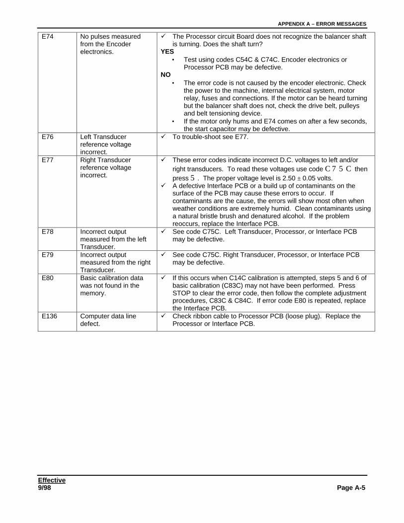
APPENDIX A – ERROR MESSAGES
Effective9/98 Page A-5
E74 No pulses measuredfrom the Encoderelectronics.
ü The Processor circuit Board does not recognize the balancer shaftis turning. Does the shaft turn?
YES• Test using codes C54C & C74C. Encoder electronics or
Processor PCB may be defective.NO
• The error code is not caused by the encoder electronic. Checkthe power to the machine, internal electrical system, motorrelay, fuses and connections. If the motor can be heard turningbut the balancer shaft does not, check the drive belt, pulleysand belt tensioning device.
• If the motor only hums and E74 comes on after a few seconds,the start capacitor may be defective.
E76 Left Transducerreference voltageincorrect.
ü To trouble-shoot see E77.
E77 Right Transducerreference voltageincorrect.
ü These error codes indicate incorrect D.C. voltages to left and/orright transducers. To read these voltages use code C75C thenpress 5. The proper voltage level is 2.50 ± 0.05 volts.
ü A defective Interface PCB or a build up of contaminants on thesurface of the PCB may cause these errors to occur. Ifcontaminants are the cause, the errors will show most often whenweather conditions are extremely humid. Clean contaminants usinga natural bristle brush and denatured alcohol. If the problemreoccurs, replace the Interface PCB.
E78 Incorrect outputmeasured from the leftTransducer.
ü See code C75C. Left Transducer, Processor, or Interface PCBmay be defective.
E79 Incorrect outputmeasured from the rightTransducer.
ü See code C75C. Right Transducer, Processor, or Interface PCBmay be defective.
E80 Basic calibration datawas not found in thememory.
ü If this occurs when C14C calibration is attempted, steps 5 and 6 ofbasic calibration (C83C) may not have been performed. PressSTOP to clear the error code, then follow the complete adjustmentprocedures, C83C & C84C. If error code E80 is repeated, replacethe Interface PCB.
E136 Computer data linedefect.
ü Check ribbon cable to Processor PCB (loose plug). Replace theProcessor or Interface PCB.
APPENDIX A – ERROR MESSAGES
EffectivePage A-6 9/98
Effective9/98 Page B-1
APPENDIX BSOFTWARE / HARDWARE REVISION
This appendix gives a breakdown of each software revision available. The first section lists the softwarerevision number, and the modifications made to the software. The second section lists the hardware revisionsmade to the machine.
SOFTWARE REVISONS
v New release software, 6/98.
HARDWARE REVISIONS
No hardware revisions exist as of this writing.
Version 1.00

APPENDIX B SOFTWARE / HARDWARE REVISION
EffectivePage B-2 9/98
Effective9/98 Page C-1
APPENDIX CKIT INSTALLATION INSTRUCTIONS
Please file future kit installation instructions here in alphanumeric sequence. At the time of this writing, noupdate kits are available (7/29/98).
APPENDIX C KIT INSTALLATION INSTRUCTIONS
EffectivePage C-2 9/98