wheel set - shimanosi.shimano.com/pdfs/dm/dm-rcwh001-00-eng.pdf · installation of cassette...
TRANSCRIPT
(English) DM-RCWH001-00
WH-RX31SM-AX720-100x12SM-AX720-142x12
Dealer's Manual
ROAD MTB Trekking
City Touring/Comfort Bike
URBAN SPORT E-BIKE
Wheel Set
2
CONTENTS
IMPORTANT NOTICE ............................................................................................. 3
TO ENSURE SAFETY ............................................................................................... 4
LIST OF TOOLS TO BE USED .................................................................................. 7
INSTALLATION ....................................................................................................... 9Tire size .........................................................................................................................................................9
Installation of cassette sprocket ..................................................................................................................9
MAINTENANCE .................................................................................................... 12Spoke lacing ...............................................................................................................................................12
Replacement of the spokes .......................................................................................................................13
Pulling out the hub axle ............................................................................................................................14
Cautions on the use of tubeless tires ........................................................................................................19
3
IMPORTANT NOTICE
IMPORTANT NOTICE
• This dealer's manual is intended primarily for use by professional bicycle mechanics. Users who are not professionally trained for bicycle assembly should not attempt to install the components themselves using the dealer's manuals. If any part of the information on the manual is unclear to you, do not proceed with the installation. Instead, contact your place of purchase or a local bicycle dealer for their assistance.
• Make sure to read all instruction manuals included with the product.
• Do not disassemble or modify the product other than as stated in the information contained in this dealer's manual.
• All dealer's manuals and instruction manuals can be viewed on-line on our website (http://si.shimano.com).
• Please observe the appropriate rules and regulations of the country, state or region in which you conduct your business as a dealer.
For safety, be sure to read this dealer's manual thoroughly before use, and follow it for correct use.
The following instructions must be observed at all times in order to prevent personal injury and physical damage to equipment and surroundings.The instructions are classified according to the degree of danger or damage which may occur if the product is used incorrectly.
DANGER
Failure to follow the instructions will result in death or serious injury.
WARNING
Failure to follow the instructions could result in death or serious injury.
CAUTION
Failure to follow the instructions could cause personal injury or physical damage to equipment and surroundings.
4
TO ENSURE SAFETY
TO ENSURE SAFETY
WARNING
• Be sure to follow the instructions provided in the manuals when installing the product.It is recommended to use genuine Shimano parts only. If parts such as bolts and nuts become loose or damaged, the bicycle may suddenly fall over, which may cause serious injury. In addition, if adjustments are not carried out correctly, problems may occur, and the bicycle may suddenly fall over, which may cause serious injury.
• Be sure to wear safety glasses or goggles to protect your eyes while performing maintenance tasks such as replacing parts.
• After reading the dealer's manual thoroughly, keep it in a safe place for later reference.
Be sure to also inform users of the following:
• Check that the wheels are fastened securely before riding the bicycle. If the wheels are loose in any way, they may come off the bicycle and serious injury may result.
• This wheel set is designed for recreational use. Do not use this wheel set for aggressive uses such as competition.
• Before use, check the wheels to make sure that there are no bent or loose spokes, dents, scratches or cracks on the rim surface; do not use the wheel if any of these problems are found. The wheel may break, and you may fall.
• If the quick release mechanism is not used correctly, the wheel may come off the bicycle and serious injury could result. Read the Service Instructions for the quick release mechanism thoroughly before use.
• These wheels are designed exclusively for use with disc brakes. Do not use these wheels with rim brakes.
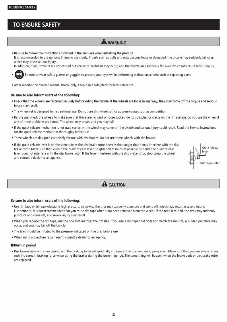
• If the quick release lever is on the same side as the disc brake rotor, there is the danger that it may interfere with the disc brake rotor. Make sure that, even if the quick release lever is tightened as much as possible by hand, the quick release lever does not interfere with the disc brake rotor. If the lever interferes with the disc brake rotor, stop using the wheel and consult a dealer or an agency.
Quick release lever
Disc brake rotor
CAUTION
Be sure to also inform users of the following:
• Use rim tape which can withstand high pressure, otherwise the tires may suddenly puncture and come off, which may result in severe injury. Furthermore, it is not recommended that you reuse rim tape after it has been removed from the wheel. If the tape is reused, the tires may suddenly puncture and come off, and severe injury may result.
• When you replace the rim tape, use the one that matches the rim size. If you use a rim tape that does not match the rim size, a sudden puncture may occur, and you may fall off the bicycle.
• The tires should be inflated to the pressure indicated on the tires before use.
• When using a puncture repair agent, consult a dealer or an agency.
�Burn-in period
• Disc brakes have a burn-in period, and the braking force will gradually increase as the burn-in period progresses. Make sure that you are aware of any such increases in braking force when using the brakes during the burn-in period. The same thing will happen when the brake pads or disc brake rotor are replaced.
5
TO ENSURE SAFETY
NOTE
Be sure to also inform users of the following:
• Do not lubricate the internal parts of the hub. Otherwise, grease will flow out.
• It is recommended that you ask a bicycle dealer to adjust the spoke tensions if there is any deviation in the spokes and after the first 1,000km of riding.
• Do not use detergent or other chemicals when wiping the wheel, otherwise the sticker on the rim or the paint may come off.
• Products are not guaranteed against natural wear and deterioration from normal use and aging.
• For maximum performance we highly recommend Shimano lubricants and maintenance products.
For Installation to the Bicycle, and Maintenance:
• When replacing the E-THRU Axle, make sure that the replacement E-THRU Axle is of the same model as the current E-THRU Axle attached to the frame. A different model may not be mounted properly onto the frame due to differences in axle length, screw size, housing diameter, etc.
• Use of genuine Shimano spokes and nipples is strongly recommended. Otherwise, the area where the spokes fit into the hub body may become damaged.
• If the wheel becomes stiff and difficult to turn, lubricate it with grease.
• SM-AX720 is designed for ROAD bicycles and therefore may not be used on other bicycle types.
• For compatible reflectors and spoke protectors, check the specifications table (http://www.si.shimano.com).
The actual product may differ from the illustration because this manual is intended mainly to explain the procedures for using the product.
LIST OF TOOLS TO BE USED

7
LIST OF TOOLS TO BE USED
LIST OF TOOLS TO BE USED
The following tools are needed for installation, adjustment, and maintenance purposes.
Tool Tool Tool
10mm Allen key 17mm spanner TL-LR15
15mm Allen key 20mm spanner TL-SR21
13mm spanner Adjustable wrench
15mm spanner Spoke plug wrench

INSTALLATION
9
INSTALLATION
Tire size
INSTALLATION
� Tire size
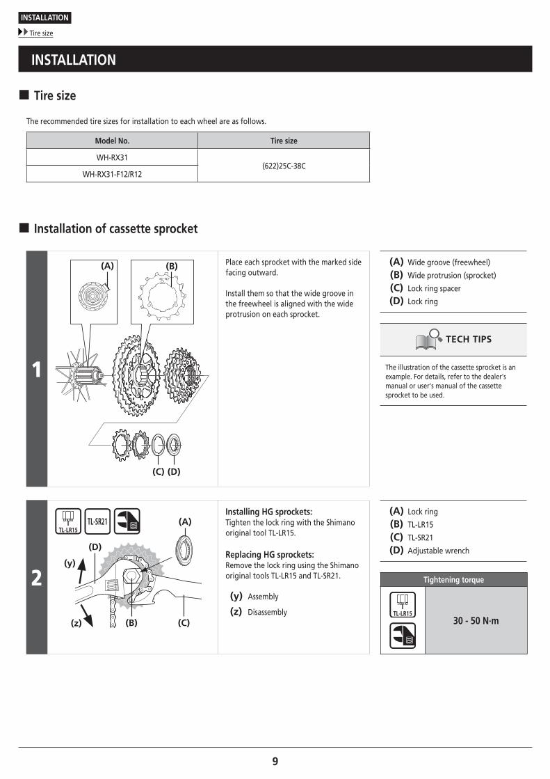
The recommended tire sizes for installation to each wheel are as follows.
Model No. Tire size
WH-RX31(622)25C-38C
WH-RX31-F12/R12
� Installation of cassette sprocket
1
(D)(C)
(B)(A) Place each sprocket with the marked side facing outward.
Install them so that the wide groove in the freewheel is aligned with the wide protrusion on each sprocket.
(A) Wide groove (freewheel)
(B) Wide protrusion (sprocket)
(C) Lock ring spacer
(D) Lock ring
The illustration of the cassette sprocket is an example. For details, refer to the dealer's manual or user's manual of the cassette sprocket to be used.
2
(B) (C)
(A)
(y)
(z)
(D)
Installing HG sprockets: Tighten the lock ring with the Shimano original tool TL-LR15.
Replacing HG sprockets: Remove the lock ring using the Shimano original tools TL-LR15 and TL-SR21.
(y) Assembly
(z) Disassembly
(A) Lock ring
(B) TL-LR15
(C) TL-SR21
(D) Adjustable wrench
Tightening torque
30 - 50 N·m
10
INSTALLATION
Installation of cassette sprocket
NOTE
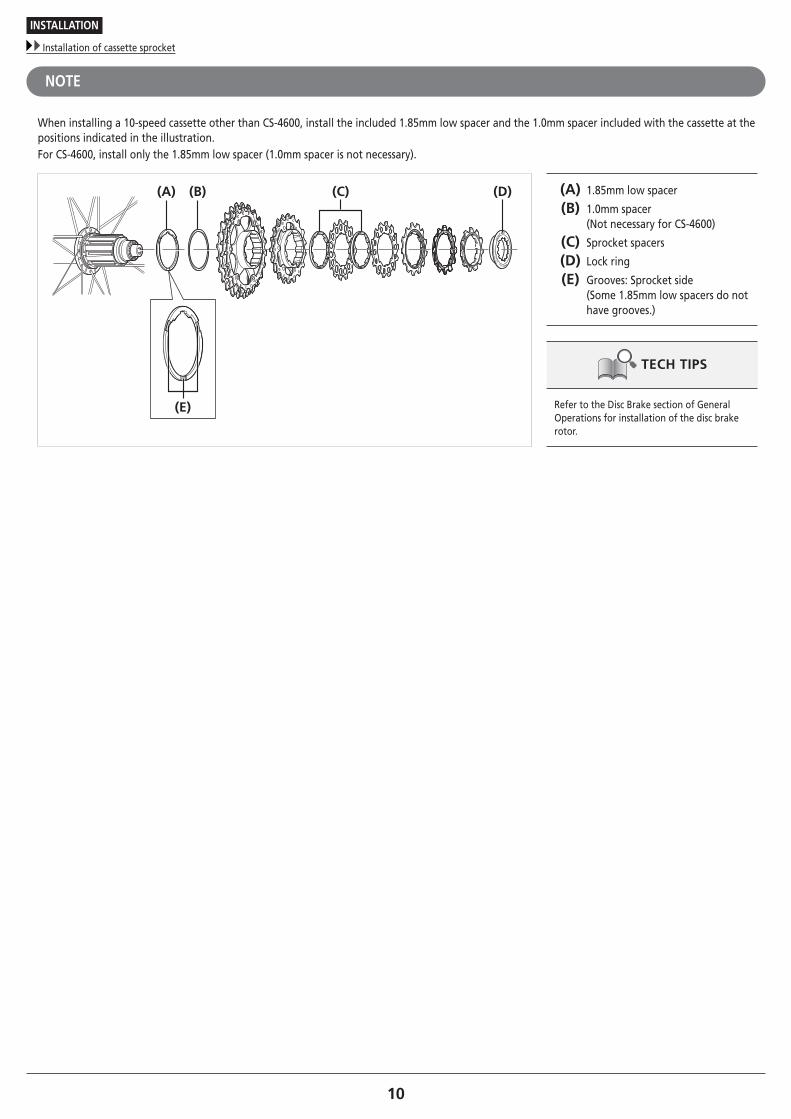
When installing a 10-speed cassette other than CS-4600, install the included 1.85mm low spacer and the 1.0mm spacer included with the cassette at the positions indicated in the illustration. For CS-4600, install only the 1.85mm low spacer (1.0mm spacer is not necessary).
(C) (D)(A) (B)
(E)
(A) 1.85mm low spacer
(B) 1.0mm spacer (Not necessary for CS-4600)
(C) Sprocket spacers
(D) Lock ring
(E) Grooves: Sprocket side (Some 1.85mm low spacers do not have grooves.)
Refer to the Disc Brake section of General Operations for installation of the disc brake rotor.

MAINTENANCE
12
MAINTENANCE
Spoke lacing
MAINTENANCE
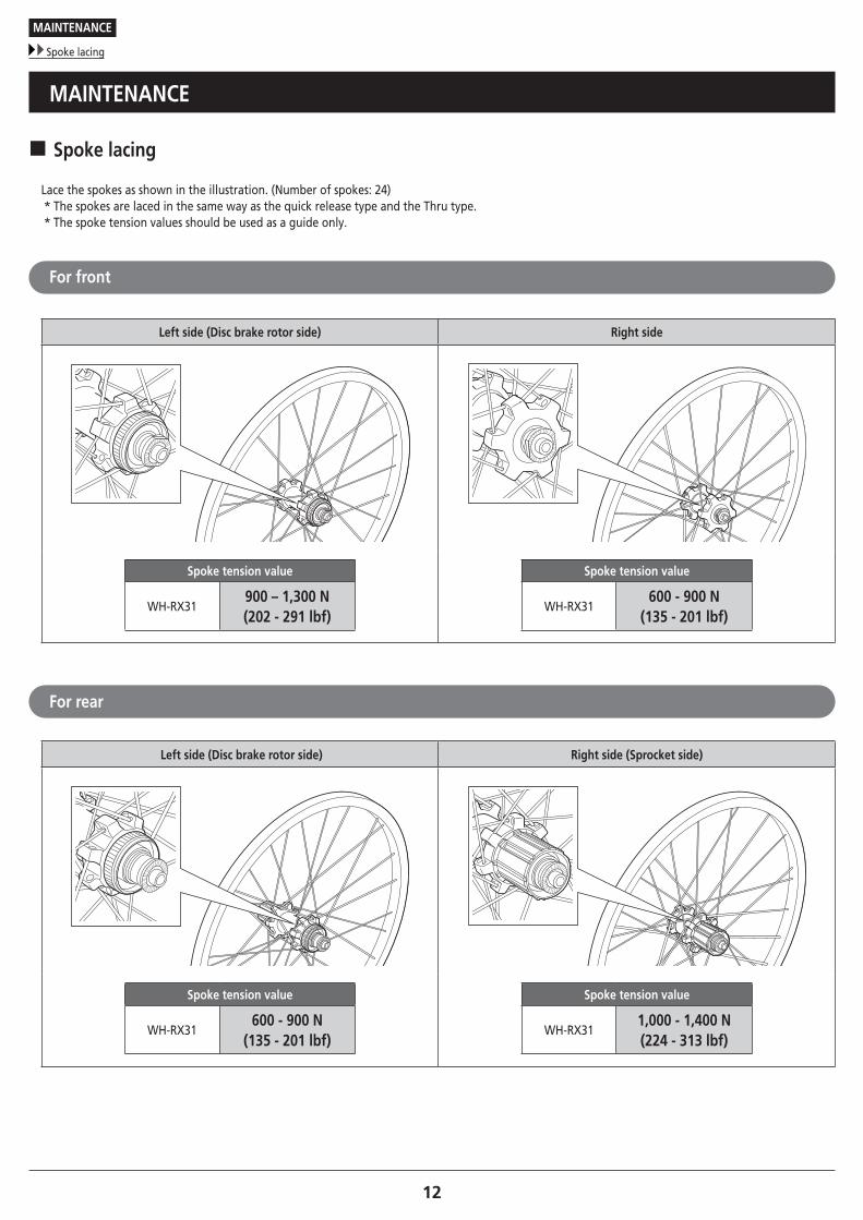
� Spoke lacing
Lace the spokes as shown in the illustration. (Number of spokes: 24)* The spokes are laced in the same way as the quick release type and the Thru type.* The spoke tension values should be used as a guide only.
For front
Left side (Disc brake rotor side) Right side
Spoke tension value
WH-RX31900 – 1,300 N(202 - 291 lbf)
Spoke tension value
WH-RX31600 - 900 N
(135 - 201 lbf)
For rear
Left side (Disc brake rotor side) Right side (Sprocket side)
Spoke tension value
WH-RX31600 - 900 N
(135 - 201 lbf)
Spoke tension value
WH-RX311,000 - 1,400 N(224 - 313 lbf)

13
MAINTENANCE
Replacement of the spokes
� Replacement of the spokes
(A)
(B)
Install the spokes by inserting them through the hub as shown in the illustration.
(A) Spoke
(B) Nipple
14
MAINTENANCE
Pulling out the hub axle
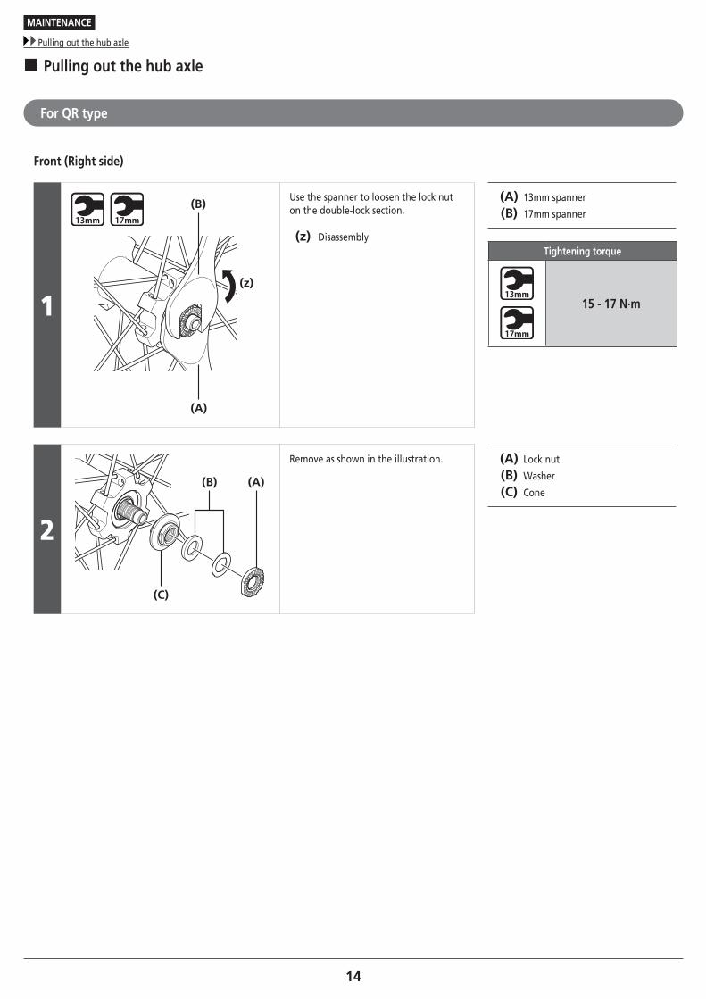
� Pulling out the hub axle
For QR type
Front (Right side)
1(z)
(B)
(A)
Use the spanner to loosen the lock nut on the double-lock section.
(z) Disassembly
(A) 13mm spanner
(B) 17mm spanner
Tightening torque
15 - 17 N·m
2
(A)(B)
(C)
Remove as shown in the illustration. (A) Lock nut
(B) Washer
(C) Cone
15
MAINTENANCE
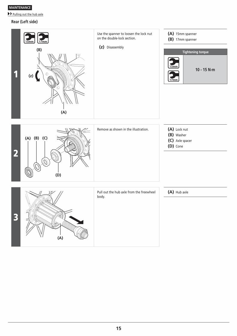
Pulling out the hub axle
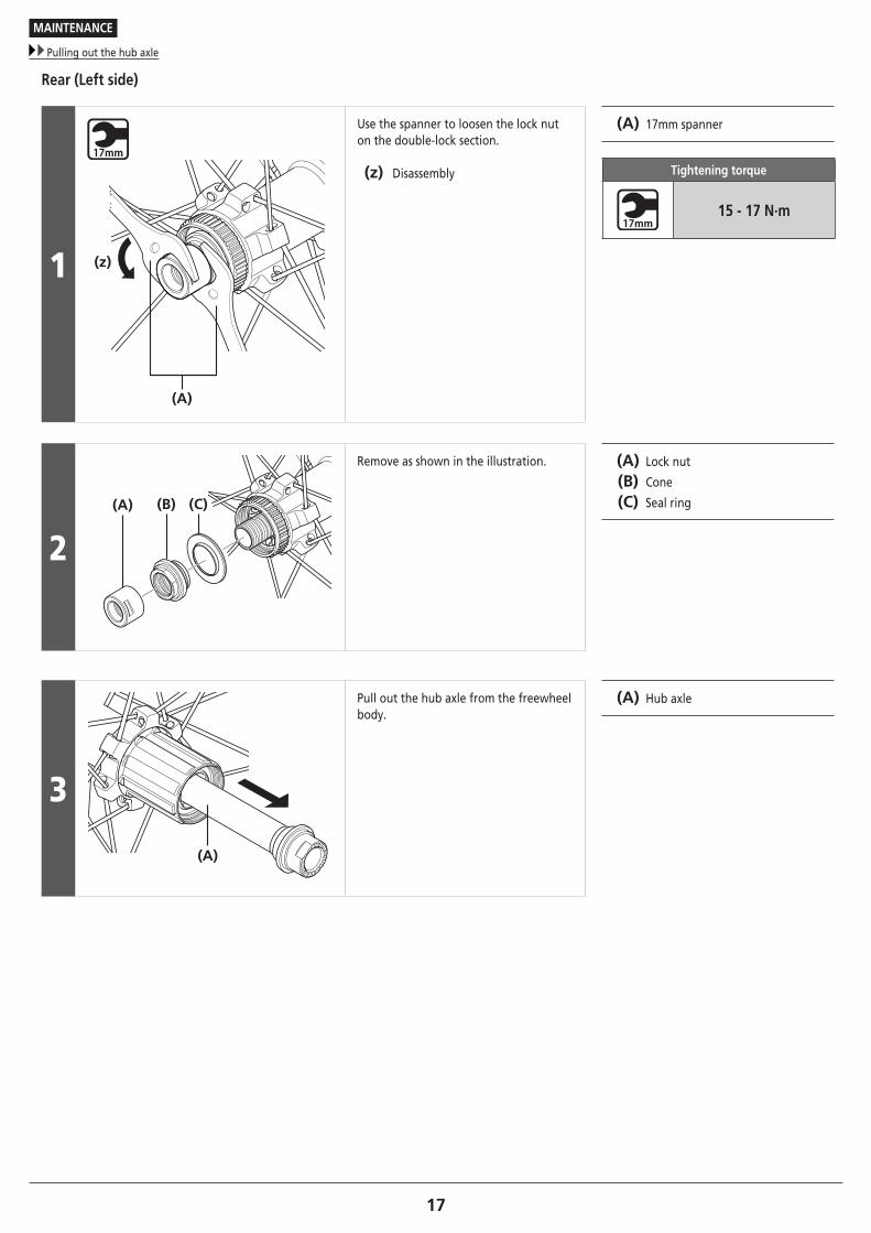
Rear (Left side)
1 (z)
(B)
(A)
Use the spanner to loosen the lock nut on the double-lock section.
(z) Disassembly
(A) 15mm spanner
(B) 17mm spanner
Tightening torque
10 - 15 N·m
2
(A)
(D)
(B) (C)
Remove as shown in the illustration. (A) Lock nut
(B) Washer
(C) Axle spacer
(D) Cone
3
(A)
Pull out the hub axle from the freewheel body.
(A) Hub axle
16
MAINTENANCE
Pulling out the hub axle
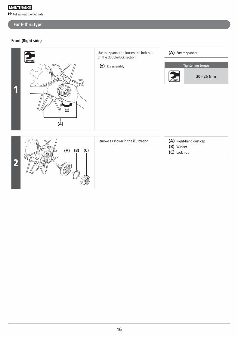
For E-thru type
Front (Right side)
1
(z)
(A)
Use the spanner to loosen the lock nut on the double-lock section.
(z) Disassembly
(A) 20mm spanner
Tightening torque
20 - 25 N·m
2(A) (B) (C)
Remove as shown in the illustration. (A) Right-hand dust cap
(B) Washer
(C) Lock nut
17
MAINTENANCE
Pulling out the hub axle
Rear (Left side)
1 (z)
(A)
Use the spanner to loosen the lock nut on the double-lock section.
(z) Disassembly
(A) 17mm spanner
Tightening torque
15 - 17 N·m
2(A) (B) (C)
Remove as shown in the illustration. (A) Lock nut
(B) Cone
(C) Seal ring
3
(A)
Pull out the hub axle from the freewheel body.
(A) Hub axle

18
MAINTENANCE
Pulling out the hub axle
Replacement of the freewheel body
QR type
(y) (z)
(B)(A) (C) (D)
E-THRU type
(y) (z)
(B)(A) (E)
(y) (z)
After removing the hub, remove the freewheel body fixing bolt (inside the freewheel body), and then replace the freewheel body.
(y) Disassembly
(z) Assembly
(A) Freewheel body washer
(B) Freewheel body
(C) Freewheel body fixing bolt
(D) 10mm Allen key
(E) 15mm Allen key
Tightening torque for QR type
35 - 50 N·m
Tightening torque for E-THRU type
150 N·m
NOTE
Do not attempt to disassemble the freewheel body, because it may result in a malfunction.
E-THRU typeThe correct position for the dust cover is when it is hidden in the freewheel body, as shown in illustration <A>.If the dust cover is in the position shown in illustration <B>, repeat the assembly process from the beginning.
<B><A>
Freewheel body
Dust cover
19To be continued on next page
MAINTENANCE
Cautions on the use of tubeless tires
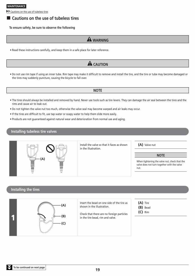
� Cautions on the use of tubeless tires
To ensure safety, be sure to observe the following
WARNING
• Read these instructions carefully, and keep them in a safe place for later reference.
CAUTION
• Do not use rim tape if using an inner tube. Rim tape may make it difficult to remove and install the tire, and the tire or tube may become damaged or the tires may suddenly puncture, causing the bicycle to fall over.
NOTE
• The tires should always be installed and removed by hand. Never use tools such as tire levers. They can damage the air seal between the tires and the rims and cause air to leak out.
• Do not tighten the valve nut too much, otherwise the valve seal may become warped and air leaks may occur.
• If the tires are difficult to fit, use tap water or soapy water to help them slide more easily.
• Products are not guaranteed against natural wear and deterioration from normal use and aging.
Installing tubeless tire valves
(A)
Install the valve so that it faces as shown in the illustration.
(A) Valve nut
NOTE
When tightening the valve nut, check that the valve does not turn together with the valve nut.
Installing the tires
1
(A)
(B)
(C)
Insert the bead on one side of the tire as shown in the illustration.
Check that there are no foreign particles in the tire bead, rim and valve.
(A) Tire
(B) Bead
(C) Rim
20
MAINTENANCE
Cautions on the use of tubeless tires
2
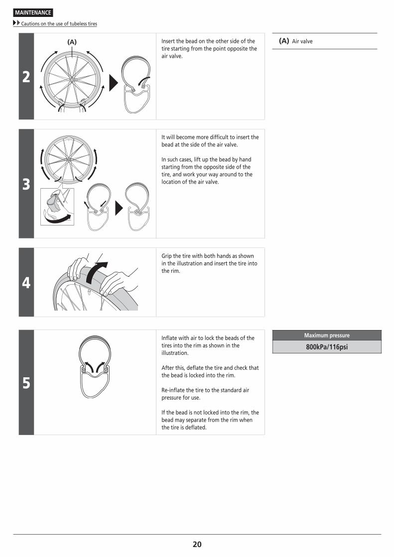
(A) Insert the bead on the other side of the tire starting from the point opposite the air valve.
(A) Air valve
3
It will become more difficult to insert the bead at the side of the air valve.
In such cases, lift up the bead by hand starting from the opposite side of the tire, and work your way around to the location of the air valve.
4
Grip the tire with both hands as shown in the illustration and insert the tire into the rim.
5
Inflate with air to lock the beads of the tires into the rim as shown in the illustration.
After this, deflate the tire and check that the bead is locked into the rim.
Re-inflate the tire to the standard air pressure for use.
If the bead is not locked into the rim, the bead may separate from the rim when the tire is deflated.
Maximum pressure
800kPa/116psi
21
MAINTENANCE
Cautions on the use of tubeless tires
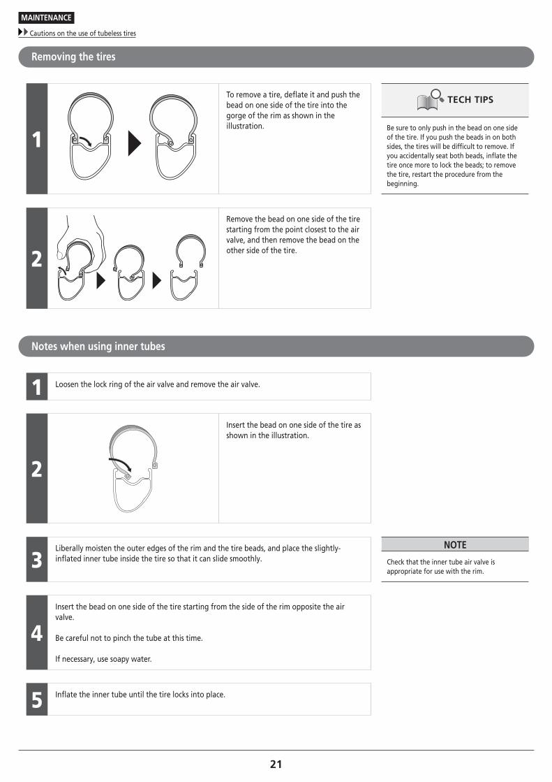
Removing the tires
1
To remove a tire, deflate it and push the bead on one side of the tire into the gorge of the rim as shown in the illustration. Be sure to only push in the bead on one side
of the tire. If you push the beads in on both sides, the tires will be difficult to remove. If you accidentally seat both beads, inflate the tire once more to lock the beads; to remove the tire, restart the procedure from the beginning.
2
Remove the bead on one side of the tire starting from the point closest to the air valve, and then remove the bead on the other side of the tire.
Notes when using inner tubes
1 Loosen the lock ring of the air valve and remove the air valve.
2
Insert the bead on one side of the tire as shown in the illustration.
3Liberally moisten the outer edges of the rim and the tire beads, and place the slightly-inflated inner tube inside the tire so that it can slide smoothly.
NOTE
Check that the inner tube air valve is appropriate for use with the rim.
4Insert the bead on one side of the tire starting from the side of the rim opposite the air valve.
Be careful not to pinch the tube at this time.
If necessary, use soapy water.
5 Inflate the inner tube until the tire locks into place.

Please note: specifications are subject to change for improvement without notice. (English) © Jan. 2016 by Shimano Inc. HTR