where ideas can grow. - maderascasais.com · 4 where ideas can grow. mayr-melnhof holz holding ag...
TRANSCRIPT

Cross-laminated timber
where ideas cangrow.

2
in safe handsMayr-Melnhof Holz is committed to sustainable and ecological practices. Informed and responsi-ble management of natural resources – regrowth and expansion of our forests – lies at the heart of our business.

3
Contents
mayr-melnhof Holz 4 - 5Properties 6 - 7target groups 8 - 9technical data 10Product range 11surface qualities 12Quality characteristics 13loading and transport 14 - 15structural design 16 - 27Component catalogue 28 - 31Component connections 32 - 33Connection techniques 34 - 35
4
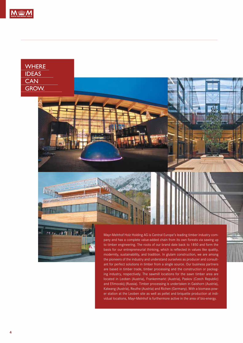
where ideas cangrow.
Mayr-Melnhof Holz Holding AG is Central Europe’s leading timber industry com-pany and has a complete value-added chain from its own forests via sawing up to timber engineering. The roots of our brand date back to 1850 and form the basis for our entrepreneurial thinking, which is reflected in values like quality, modernity, sustainability, and tradition. In glulam construction, we are among the pioneers of the industry and understand ourselves as producer and consult-ant for perfect solutions in timber from a single source. Our business partners are based in timber trade, timber processing and the construction or packag-ing industry, respectively. The sawmill locations for the sawn timber area are located in Leoben (Austria), Frankenmarkt (Austria), Paskov (Czech Republic) and Efimovskij (Russia). Timber processing is undertaken in Gaishorn (Austria), Kalwang (Austria), Reuthe (Austria) and Richen (Germany). With a biomass pow-er station at the Leoben site as well as pellet and briquette production at indi-vidual locations, Mayr-Melnhof is furthermore active in the area of bio-energy.

5
Products of mayr-melnhof Holz
Glulam beams
duo-/trio beams
laminated ceiling elements
Floor and wall beams
Cross-laminated timber
3-ply structural panels
Formwork panels
Formwork beams
mayr-melnhof Holz Holding aGTurmgasse 67 · 8700 Leoben · Austriat +43 3842 300 0 · F +43 3842 300 [email protected] · www.mm-holz.com
Esteemed Customer, thank you for your interest in our products. Please note that this document is a sales brochure and that the quoted figures are merely reference values. The document may contain typing errors and other mistakes. In preparing this sales brochure, all information was researched with due diligence. However, we cannot accept any liability for the accuracy and completeness of the figures and data stated therein. Any legal claims derived from the use of this information are therefore excluded. The content of the services we are liable for can only be defined by way of a written quotation in combination with our relevant written confirmation of your order. This sales brochure and our other sales materials are not quotations in a legal sense. For planning your project we recommend you get in personal contact with one of our members of staff who will be glad to assist you on a non-binding basis. Any copying of this material in full or in part requires the expressed approval of the MM Holz Group.

6
state of the art, environmental and flexible – developed for use in the timber construction industry
is a solid, static load-bearing and spacecreating timber panel that is ideal for any structural requirement thanks to its flexible dimensions and outstanding physical properties. Durable bonding of the cross-wise layered construction made of high-quality raw material guarantees that the components are ab-solutely dimensionally stable and rigid.
areas of application•Familyhousesandapartmentbuildings•Multi-storeyresidentialbuildings•Buildingextensions•Urbandevelopment•Nurseriesandschools•Commercial,officeandindustrialbuildings•Agriculturalbuildings•Tourismandleisure•Modularbuildings
Properties•Solid,value-maintainingconstruction•Spacegainduetoreducedcomponentthickness•Flexibledesignwithoutgridpattern•Excellentshapeanddimensionalaccuracy•Outstandingstructuralproperties•Prefabricatedelements,simplelow-dustand
low-noise assembly•Shortbuildingtimeduetodryconstruction•Natural,sustainableconstructionmaterial•CO
2 reservoir
european technical approvaleta-09/0036
eC Certificate of Conformity1359-CPd-0196
German technical approvalZ-9.1-638 (dibt)
environmental seal of approval(ibr rosenheim)
Cross-laminated timber
Chain of Custody

7
Weighty arguments take shape The range of applications extend from individually designed detached houses to large-volume building projects. The large-format solid wood panels make it possible to cope effort-lessly with special static challenges.
The clearly structured, layered design principle with simple joint-ing details guarantees extremely cost-effective use in all areas of building.
Rapid and straightforward assembly of the elements results in a significant reduction of building time. The creative flexibility meets the needs of modern architecture fans and also of enthusi-asts of traditional building styles.
Facts mmcrosslam:types of wood•Spruce
thicknesses•60–280mm
Formats•max.3.00x16.50m
technical approvals•EuropeanTechnicalApproval
ETA-09/0036•GermanTechnicalApproval
Z-9.1-638
surface qualities•Industrial•Standard•Livingspacequality

8
Different demands require innovative solutions
Housing construction With its permeable properties, is the feel-good construction material for housing construction. In that, moisture-regulating walls not only provide for an optimal indoor climate, but also for excellent sound insulation. With its outstanding insula-tion properties, a passive house standard is possible without any problem; thermal insulation during summer is guaranteed, too. The walls and ceilings of the building shell already provide for warmth and cosiness. Furthermore, is a real space-saver: valuable space is gained with slim wall structures.
tourism and leisure not only excels with its dry and solid construction,
but also combines sustainable building with the latest in archi-tecture. Cross-laminated timber buildings enable unique designs and thus provide for charisma and distinctiveness towards the outside. Furthermore, crosslam buildings have an extraordinary eco-balance and thus send a clear signal for environmental and climateawareness.Ultimately,moisture-regulatingwallsprovidefor a pleasant indoor climate, which is a feel-good bonus for all the guests.
schools and nurseriesFor the construction of pedagogical facilities, timber construction is still on the advance. Especially for school buildings and other childcare facilities, the positive qualities and the feel-good fac-tor of timber as a construction material are increasingly utilised. Thus, for example, it has been scientifically proven that the stress level of the occupants of timber buildings is lower than in build-ings of conventional materials. Furthermore, individual timber ele-ments may be used as design elements. Cost-effective and flex-ible solutions for indoor concepts round off the overall package.
modular buildingsWith complete room modules (incl. furnishings, surfaces, etc.),
excels with numerous advantages in modular con-struction. A continuous process chain at the factory enables not only highest quality standards, but also enormous time and cost savings compared to conventional manufacturing. Extremely short and weather-independent assembly times provide for fast project completion. The noise burden for neighbours, too, is con-siderable reduced due to the short construction period. Modular crosslam buildings additionally have a pleasant and comfortable indoor climate, and the passive house standard is possible with-out any problem, too.

9
multi-storey buildings Due to the high load-bearing capacity, is excellently suited for multi-storey residential and administrative buildings. The innovative construction material excels with very good building physics and fire safety qualities. In the area of earthquake safety, the solid timber material offers decisive advantages compared to traditional brick and mortar buildings. However, enables not only the manufacture of components at storey height. With prefabricated crosslam elements, even entire residential unitscanbesetupinlessthantwodays.Slimconstructionthick-nesses furthermore result in additional space savings.
Urban constructionWith its low net weight, offers essential advantages especially upon construction at restricted urban locations. The high degree of prefabrication, joining, milled-in door and window openings, preinstalled lines and finished visible surfaces enable substantial shorter assembly times than with other construction materials. Large-format, ready-to-assemble wall components may also be used directly from the delivery truck. Furthermore,
offers numerous possibilities to make existing buildings future-proof with redevelopment, and it is also suited for additions to buildings and closing gaps between buildings. Even if the top-most storey ceiling is not dimensioned for the loads of a further residential storey, a new ceiling made of crosslam can be positioned on the load-transferring external wall.
Commercial and industrial construction provides industrial construction with almost un-
limited possibilities. Components can be manufactured at storey height as well as at building length. In that, very large spans are possible with crosslam ribs or box elements. Restrictions in fas-tening loads are a thing of the past, too. Even insulations, facing formwork and façade elements can be fastened to the individual elements without any problem. Door and window lintels as well as substitutions for ceiling openings are no longer applicable in cross-laminated timber construction. From an economic point of view, too, building with pays off. With the numer-ous possibilities for prefabrication, a short construction period is guaranteed. Furthermore, construction with crosslam demon-strably requires fewer transports and therewith also is an environ-ment-friendly alternative.

10
GluingMelamineresin-basedadhesive,AdhesiveTypeIacc.toEN301approved for the gluing of load-bearing timber components, for both interiors and exteriors.
WeightApprox. 480 kg/m³ for determination of the transport weight5kN/m³accordingtoEN1991-1-1:2002forstaticcalculations
moisture content 12% (± 2%)
dimensional stabilityII to panel plane 0.01% per % change in moisture content ⊥ to panel plane 0.20% per % change in moisture content
thermal conductivityλ = 0.10 W/m2K
Heat capacityc = 1.60 kJ/kgK
Water vapour resistance factorμ = 60 (at 12% moisture content)
airtightnessAirtight from a panel thickness of 90 mm
sound insulationDependent on wall or ceiling build-up
reaction to fireAccordingtoEN13501:D,s2,d0
Fire resistance Acc. to Classification Report of Holz Forschung Austria,EN13501-2:REI30-REI120
Charring rateAccording to the Classification Report of HFA, the average charring rate across several layers is for walls: 0.64 mm/minfor ceilings: 0.71 mm/min
service classesServiceclasses1or2acc.toETA-09/0036
Technical data
Product is a large-format, solid timber panel (cross-lami-
nated timber panel) with multi-layered, crosswise cross-section lay-up.
lay-up and production Finger-jointed and planed lamellas are loosely laid next to each other and the flat surfaces of the layers glued at right angles to one another. To avoid uncontrolled stress cracks, the narrow sides are not glued. The layers are pushed laterally to dimension before applying thepressure (1.2N/mm2) in order to obtain a gap-free surface.
dimensionslengths to 16.50 mWidths to 3.00 m thicknesses 60 to 280 mmstandard widths 2.40 m/2.65 m/2.75 m/ 2.90 m/3.00 m
technical approvalsEuropean Technical Approval ETA−09/0036 German Technical Approval Z-9.1-638
types of woodSpruce(Piceaabies)fromdomesticforests;otherwoodspecieson request.
lamellas Kiln-dried, quality graded and finger-jointed
strength classes (lamellas)C24acc.toEN338(equivalenttoS10acc.toDIN4074)A proportion of max. 10% C16 is permissible (ETA-09/0036)

11
description layers Panel build-up thickness standard widths length
[mm] [mm] [m] [m]
60* 3s 3 20 20 20 60
2.402.652.75 2.903.00
max. 16.50
80 3s 3 30 20 30 80
90 3s 3 30 30 30 90
100 3s 3 40 20 40 100
120 3s 3 40 40 40 120
100 5s 5 20 20 20 20 20 100
120 5s 5 30 20 20 20 30 120
140 5s 5 40 20 20 20 40 140
160 5s 5 40 20 40 20 40 160
180 5s 5 40 30 40 30 40 180
200 5s 5 40 40 40 40 40 200
200 7ss 7 60 20 40 20 60 200
220 7s 7 40 20 40 20 40 20 40 220
220 7ss 7 80 20 20 20 80 220
240 7s 7 40 20 40 40 40 20 40 240
240 7ss 7 80 20 40 20 80 240
260 7ss 7 80 30 40 30 80 260
280 7ss 7 80 40 40 40 80 280
Our structures have been standardised for universal application! However, on re-quest, we also offer you our previous dimensions or indi-vidual solutions, respectively.
Product range
* identically producible pair-wise only, on requestss outer layers consist of 2 top layers with parallel fibre orientation According to the application, the orientation of the top layer can be selected in the longitudinal (DL) or transverse (DQ) direction.

12
Surfaces and qualities
industrial quality For non-visual applications in compliance with all structural re-quirements, for subsequent installation (e.g. plasterboard).•Thetoplamellasareexclusivelysortedaccordingtothesorting
criteriaoftheload-bearingstrengthC24inlinewithEN338. A proportion of max. 10% C16 is permissible (ETA-09/0036).•Colourvariationsofindividuallamella(e.g.bluestain)aswellas
loose knots, bark ingrowths and resin pockets are possible.•Isolatedgapsintheouterlayers,gluestainsaswellasisolated
pressure points and markings can appear.•Surfaceplaned
standard qualityWith additional requirements for visual applications.•Stringentvisualcriteriaforouterlayersareappliedinaddition
to the sorting criteria for load-bearing strength.•Selected outer lamellas with healthy intergrown knots. A few
isolated loose knots are possible, defects and small resin pock-ets are permissible.
•Planedandsandedsurface.
living space qualityFor high requirements in the visible component area. Here, raw materials of the highest optical sawn-timber grading classes are exclusively used. The lamellas have a maximum thickness of 20 mm and are processed in a pre-glued and pre-dried state, which guarantees minimum joint opening. The surface is ground, and in order to avoid shrinkage cracks, there is no additional joint gluing.
noteTimber is a natural product. Variations in the surface quality can occur with even the most careful selection of the raw material. The appearance of the surface is determined by the board structure of the top layer. Gaps may occur between the individualboardsovertimeduetoshrinkage,etc.Superficialdry-ing cracks are also possible.

13
Quality characteristics
Criteria industrial quality standard quality living space quality
Open joints Upto4mm Upto4mm Upto2mm
SurfacefinishPlaned (rotating) (rotation traces)
Ground Ground
Mixture of types of wood Admissible In individual cases Notadmissible
Tightly integrown knots Admissible Admissible Admissible
Black/looseknots Admissible Admissible Admissible
Pitch pockets Admissible Admissible up to 10 x 90 mm Admissible up to 5 x 50 mm
Ingrown bark Admissible In individual cases Notadmissible
Dry cracks Admissible Admissible Admissible in individual cases
Wane Admissible Notadmissible Notadmissible
Voids NorequirementsAdmissible in individual cases,
Touch up wigh other timberAdmissible in individual cases,
Touch up with other timber
Insect infestationIn individual cases, holes up to 2
mm admissibleNotadmissible Notadmissible
Insect infestationIn individual cases, holes up to 2
mm admissibleNotadmissible Notadmissible
Compression wood, red stripes, box
Admissible Admissible Admissible in individual cases

14
Loading and transport
max
. 4,0
00
1,20
0
max. 16,500
max
. 4,
100
1,10
0
950 950
3,00
0
loading plans In order to ensure an optimal assembly sequence of cross-lami-nated timber, it is necessary to determine a setup sequence dur-ing ordering already. According to this determination, simultane-ously with the product release, a loading sequence is defined for the means of transport that will be used. A consensus must be reached between the customer’s wishes and the practical pos-sibilities for loading, wherein the legal regulations in respect of securing of the cargo must be considered and complied with, too.
In the interest of timely customer information, exact loading plans are communicated several days prior to delivery, including the detailed positions of each individual component on the load and ensuring that any unnecessary installation and assembly delays or lifting work will be avoided.
1. 2.
Symbolic representation
Symbolic representation
15
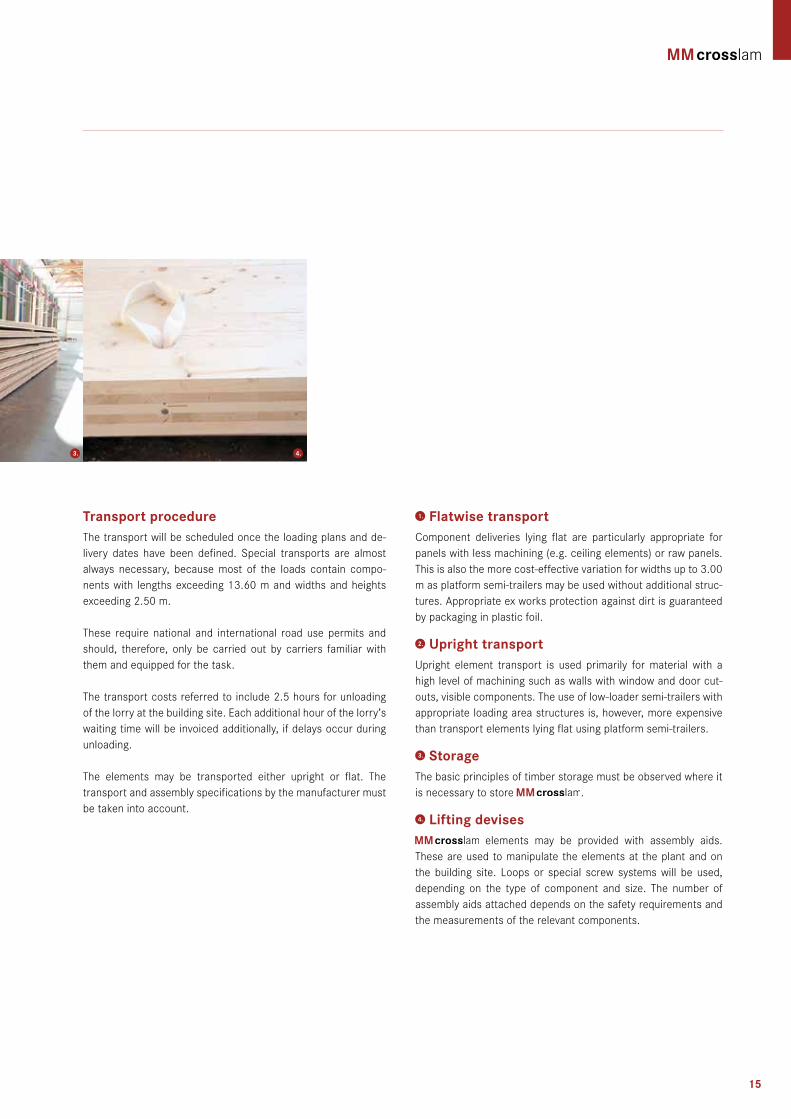
transport procedure The transport will be scheduled once the loading plans and de-livery dates have been defined. Special transports are almostalways necessary, because most of the loads contain compo-nents with lengths exceeding 13.60 m and widths and heights exceeding 2.50 m.
These require national and international road use permits and should, therefore, only be carried out by carriers familiar with them and equipped for the task.
The transport costs referred to include 2.5 hours for unloading of the lorry at the building site. Each additional hour of the lorry’s waiting time will be invoiced additionally, if delays occur during unloading.
The elements may be transported either upright or flat. The transport and assembly specifications by the manufacturer must be taken into account.
1. Flatwise transportComponent deliveries lying flat are particularly appropriate for panels with less machining (e.g. ceiling elements) or raw panels. This is also the more cost-effective variation for widths up to 3.00 m as platform semi-trailers may be used without additional struc-tures. Appropriate ex works protection against dirt is guaranteed by packaging in plastic foil.
2. Upright transportUpright element transport is used primarily for material with ahigh level of machining such as walls with window and door cut-outs, visible components. The use of low-loader semi-trailers with appropriate loading area structures is, however, more expensive than transport elements lying flat using platform semi-trailers.
3. storage The basic principles of timber storage must be observed where it is necessary to store .
4. lifting devises elements may be provided with assembly aids.
These are used to manipulate the elements at the plant and on the building site. Loops or special screw systems will be used, depending on the type of component and size. The number of assembly aids attached depends on the safety requirements and the measurements of the relevant components.
3. 4.

16
General information Components made of are designed and executed according to the following standards:
•DesignaccordingtoEN1995(Eurocode5)takingaccount of national regulations as well as the Appendices 2 to 4 of European Technical Approval ETA-09/0036
or•DesignaccordingtoDIN1052:2008takingaccountofthe
German Technical Approval (Z-9.1-638)
The structural analysis for must be conducted in each individual case, and the standards and regulations applica-ble at the site of use must be complied with.
Analyses of the stress distribution and internal forces and mo-ments must be conducted according to the composite theory al-lowing for shear deformations.
building practice approximation method for calculation of cutting forces and deformations.An approximation method is required in practical use. Here, the calculation is carried out for a beam under bending moment with flexible joining means (compare DIN1052;EN1995-1-1,Appen-dixB),butthesheardeformationofthetransverselayersistakeninto consideration instead of the flexibility of the joining means.Usingthisapproach,itispossibletoachieveagoodapproxima-tion for the stress and deformation calculations.
Structural design
At the same time, for the actual design the moments of inertia are multiplied by a reduction factor – which takes into account the net moments of inertia and the rolling shear deformation of the transverse layers.Usingtheeffectivemomentsofinertia(I
eff) obtained as a result, it is possible to calculate the cutting forces and deformations for beams under bending moments with rigid bonds.
note: The solution only applies exactly for single span beams with si-nusoidal uniform load. It should also be noted that the effective moments of inertia I
eff depend on the width between supports of the panels. The shorter the width between supports, the greater the proportion of shear deformation and thus also the percentage reduction of the moments of inertia (compare table of cross-sec-tionalvalues).Beyondthis,amoreaccuratecalculationmethodis necessary particularly in the case of point loads and very short beam lengths.
In the case of continuous beams, the width between supports of the field concerned should be used for the width between sup-ports for selection of the effective moment of inertia 4 /5 I
eff. In the case of cantilever beams, double the protruding length should beused(cf.EN1995-1-1,AppendixB).However,calculationsofcutting force and deformation values must be performed, using the actual widths between supports or protruding lengths.
This approximation method is also the basis of the design charts.

17
mm crosslam
lay-up afull anet ifull ieff (dependent on span between supports of single span beam)
bold = parallel to fibre direction of
outer layers
1 m 2 m 3 m 4 m 5 m 6 m 8 m
Total ticknesses
(bxd3) /12
Ieff Ieff /Ifull Ieff Ieff /Ifull Ieff Ieff /Ifull Ieff Ieff /Ifull Ieff Ieff /Ifull Ieff Ieff /Ifull Ieff Ieff /Ifull
[ ] [mm] [mm] [cm²] [cm²] [cm4] [cm4] [%] [cm4] [%] [cm4] [%] [cm4] [%] [cm4] [%] [cm4] [%] [cm4] [%]
3s 60 20 20 20 600 400 1800 1230 68 1577 88 1655 92 1689 94 1704 95 1714 95 1722 96
3s 80 30 20 30 800 600 4267 2673 63 3650 86 3934 92 4045 95 4100 96 4130 97 4160 98
3s 90 30 30 30 900 600 6075 3109 51 4744 78 5295 87 5539 91 5523 91 5700 94 5764 95
3s 100 40 20 40 1000 800 8333 4825 58 6925 83 7602 91 7877 95 8012 96 8088 97 8165 98
3s 120 40 40 40 1200 800 14400 5587 39 9846 68 11207 78 12552 87 12993 90 13247 92 13510 94
5s 100 20 20 20 20 20 1000 600 8333 3540 42 5408 65 6009 72 6253 75 6374 76 6441 77 6510 78
5s 120 30 20 20 20 30 1200 800 14400 5635 39 9560 66 11058 77 11705 81 12034 84 12220 85 12411 86
5s 140 40 20 20 20 40 1400 1000 22867 8196 36 14851 65 17751 78 19079 83 19768 86 20165 88 20577 90
5s 160 40 20 40 20 40 1600 1200 34133 11770 34 21354 63 25530 75 27441 80 28434 83 29005 85 29599 87
5s 180 40 30 40 30 40 1800 1200 48600 24838 51 31631 65 35055 72 36918 76 38020 78 39186 81
5s 200 40 40 40 40 40 2000 1200 66667 28324 42 37988 57 43261 65 46256 69 48071 72 50028 75
7ss 200 60 20 40 20 60 2000 1600 66667 49180 74 54315 81 57111 86 58764 88 60513 91
7s 220 40 20 40 20 40 20 40 2200 1600 88733 55640 63 62410 70 66161 75 68403 77 70793 80
7ss 220 80 20 20 20 80 2200 1800 88733 64319 72 72393 82 76979 87 79758 90 82755 93
7s 240 40 20 40 40 40 20 40 2400 1600 115200 74052 64 80365 70 84295 73 88626 77
7ss 240 80 20 40 20 80 2400 2000 115200 92388 80 98379 85 102008 89 105922 92
7ss 260 80 30 40 30 80 2600 2000 146467 105534 72 115312 79 121503 83 128418 88
7ss 280 80 40 40 40 80 2800 2000 182933 118810 65 132802 73 142009 78 152630 83
Calculation values ieff
All details relate to a 1 m wide panel strip
Afull Overall cross-sectionAnet Cross-sectional value for the demonstration of compressive stresses in the direction of the top layerIfull Moment of inertia of the full section – as a reference value only
Ieff Effective moment of inertia of the full section – as a reference value onlyIeff/ Ifull Ratio that specifies to what extent the cross-wise layers alter the cross-section’s effective moment of inertia
18
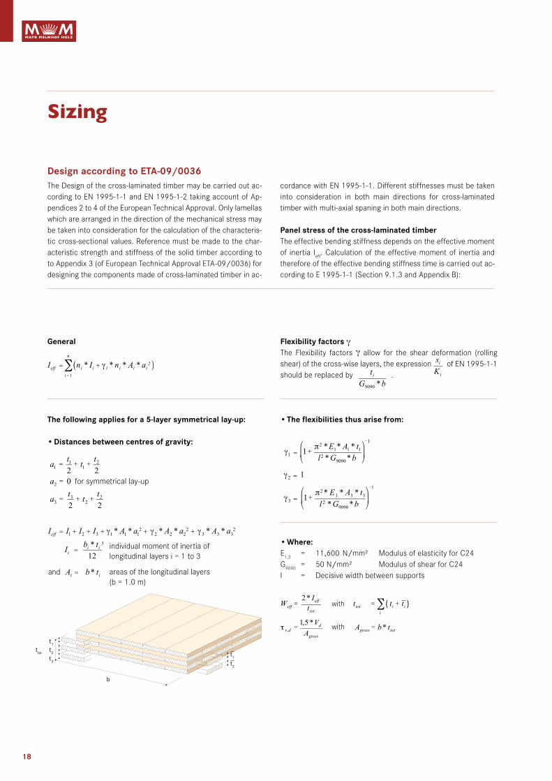
design according to eta-09/0036The Design of the cross-laminated timber may be carried out ac-cordingtoEN1995-1-1andEN1995-1-2takingaccountofAp-pendices 2 to 4 of the European Technical Approval. Only lamellas which are arranged in the direction of the mechanical stress may be taken into consideration for the calculation of the characteris-tic cross-sectional values. Reference must be made to the char-acteristic strength and stiffness of the solid timber according to to Appendix 3 (of European Technical Approval ETA-09/0036) for designing the components made of cross-laminated timber in ac-
General
the following applies for a 5-layer symmetrical lay-up:
•distances between centres of gravity:
cordancewithEN1995-1-1.Differentstiffnessesmustbetakeninto consideration in both main directions for cross-laminated timber with multi-axial spaning in both main directions.
Panel stress of the cross-laminated timberThe effective bending stiffness depends on the effective moment of inertia I
eff. Calculation of the effective moment of inertia and therefore of the effective bending stiffness time is carried out ac-cordingtoE1995-1-1(Section9.1.3andAppendixB):
Flexibility factors γThe Flexibility factors γ allow for the shear deformation (rolling shear) of the cross-wise layers, the expression ofEN1995-1-1should be replaced by .
•the flexibilities thus arise from:
•Where:E
1,3 = 11,600N/mm² ModulusofelasticityforC24G
9090 = 50N/mm² ModulusofshearforC24l = Decisive width between supports
Sizing
b
t1
t2ttot
t3
for symmetrical lay-up
and
individual moment of inertia of longitudinal layers i = 1 to 3
areas of the longitudinal layers(b = 1.0 m)
( )with
with
t1
t2

19
slab stress of the cross-laminated timberThe following equations may be used for stress in the panel plane (slab stress) under the requirements of the technical column theory:
distances between centres of gravity:
Panel loads material characteristics according to eta-09/0036
Property numerical value
strength classes of lamellas C24
modulus of elasticity:•ParalleltofibredirectionoflamellasE0, mean•PerpendiculartofibredirectionE90, mean
11,600.00N/mm2
370.00N/mm2
modulus of shear:•ParalleltofibredirectionoflamellasG090, mean•Perpendiculartothefibredirectionofthelamellas,modulusofrollingshearE90, mean
650.00N/mm2
50.00N/mm2
bending strength:•Paralleltofibredirectionoflamellasfm, k•fm, k maybeincreasedtoto28.8N/mm2 for C24 (fm, CLT, k) in accordance with the approval
referred to above
24.00N/mm2
tensile strength:•Perpendiculartothefibredirectionofthelamellasft, 90, k
0.12N/mm2
Compressive strength:•Perpendiculartothefibredirectionofthelamellasfc, 90, k
2.50N/mm2
shear strength:•Paralleltofibredirectionoflamellasfv, 090, k•Perpendiculartothefibredirectionofthelamellas(rollingshearstrength)fv, 9090, k
2.50N/mm2
1.10N/mm2
Calculation of the bending stresses and bending stiffness may be carried out using the full section of the lamella layers in the direction of stress. When calculating the shear stresses, the net area with the smaller cross-section of the two stress directions is decisive.
H
t1t2t3
Thickness of the lamella layers normal to the direction of stress
Thickness of the lamella layers in the direction of stress
where
Design value of the shear force
Maximum
t2
t1

20
slab loads
Fire resistant design The fire resistant design of is carried out in accord-ancewithEN1995orDIN1052:4102 (Eurocode1-2), respec-tively (referred to as thermal design with inclusion of the residual load-bearing capacity).
Connecting means according to eta-09/0036The load-carrying connection of elements must be carried out separately and using suitable joining means for each building task. The design of the connecting means (diameter, number und distances) should be within the responsibility of a specialist familiar with cross-laminated timber.
As a recommendation for determining the design values, refer-enceismadeto«BemessungsvorschlägefürVerbindungsmittelinBrettsperrholz»[DesignSuggestionsforJoiningMeansinCross-laminated Timber] [from Bauen mit Holz [Building with Timber]111(2009),BLASSHansJoachim,UIBELThomas]andtoExpertOpinionno.GU07-4-2-1-01of theTechnicalUniversityofGraz.Specified here are the embedment strengths for screwed andnailed joints, dowel pins, fit bolts and bolts, in addition to a design suggestion for axial stress (tension).
A distinction should be made between joints in the narrow sur-faces and those in the lateral surface when referring to joints. The static analyses of the joints must be conducted in accordance withEN13501-1-1.
Wall slab In case of stress as a wall slab (bracing ceilings and walls), it is necessary to conduct the corresponding shear stress analyses in accordance with the German Technical Approval stated above.
lintel design Only the lamella layers running parallel to the direction of force or the direction of internal forces and moments, respectively, are taken into account for the design. The height of the individual beam cross-sections must be specified in the particular case. Thus, wall slabs may also be calculated allowing for door and win-dow openings.
Wall slab as column Only the lamella layers running parallel to the direction of force are taken into account for the design of the load-carrying capacity at panel level. The buckling analysis required for this must be con-ducted according to the equivalent member method in accord-ancewithEN1995orDIN1052,respectively.Thecorrespond-ing slenderness () and the associated reduction coefficients (k) must be determined in the process.
Vibration design It must be ensured that impacts on components or supporting structures, that are to be anticipated frequently, do not cause any vibrations, which could impair the structure’s function or lead to unease. The required analysis must be conducted in accordance withEN1995-1-1,whereinaspecialtestmustbecarriedoutforapartment ceilings with a resonant frequency not exceeding 8 Hz.
Property Numericalvalue
strength classes of lamellas C24
modulus of elasticity:•ParalleltofibredirectionoflamellasE0,mean
11,600.00N/mm2
modulus of shear:•ParalleltofibredirectionoflamellasG090,mean
250.00N/mm2
bending strength:•Paralleltofibredirectionoflamellasfm,k
24.00N/mm2
tensile strength:•Paralleltofibredirectionoflamellasft, 90, k
14.00N/mm2
Compressive strength:•Paralleltofibredirectionoflamellasfc, 90, k
21.00N/mm2
shear strength:•Paralleltofibredirectionoflamellasfv, 090, k
5.00N/mm2
Structural design
21
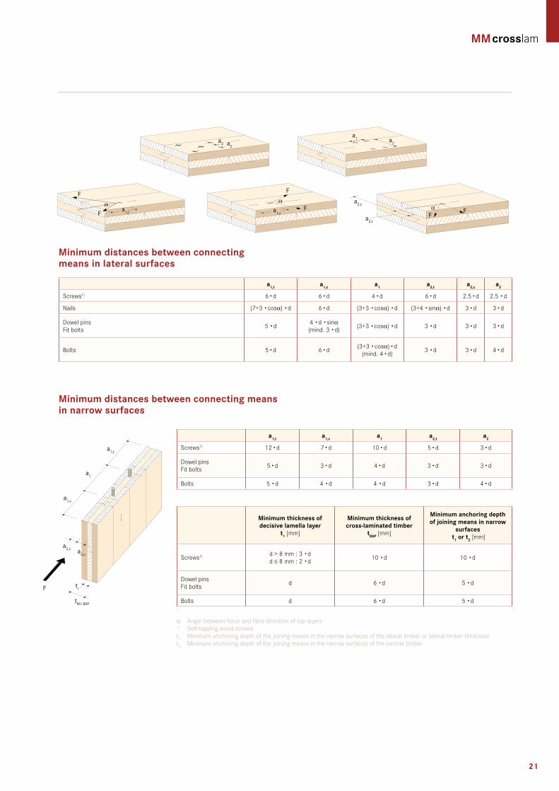
minimum distances between connecting means in lateral surfaces
minimum distances between connecting means in narrow surfaces
a1,t a1,c a1 a2,t a2,c a2
Screws1) 6 •d 6 •d 4 •d 6 •d 2.5 •d 2.5 •d
Nails (7+3 •cosα) •d 6 •d (3+3 •cosα) •d (3+4 •sinα) •d 3 •d 3 •d
Dowel pinsFit bolts 5 •d 4 •d •sinα
(mind. 3 •d) (3+3 •cosα) •d 3 •d 3 •d 3 •d
Bolts 5 •d 6 •d (3+3 •cosα) •d (mind. 4 •d) 3 •d 3 •d 4 •d
minimum thickness of decisive lamella layer
t1 [mm]
minimum thickness of cross-laminated timber
tbsP [mm]
minimum anchoring depth of joining means in narrow
surfaces t1 or t2 [mm]
Screws1) d > 8 mm : 3 •dd ≤ 8 mm : 2 •d 10 •d 10 •d
Dowel pinsFit bolts d 6 •d 5 •d
Bolts d 6 •d 5 •d
a1,t a1,c a1 a2,t a2
Screws1) 12 •d 7 •d 10 •d 5 •d 3 •d
Dowel pinsFit bolts 5 •d 3 •d 4 •d 3 •d 3 •d
Bolts 5 •d 4 •d 4 •d 3 •d 4 •d
α Angle between force and fibre direction of top layers1) Self-tappingwoodscrews t1 Minimum anchoring depth of the joining means in the narrow surfaces of the lateral timber or lateral timber thicknesst2 Minimum anchoring depth of the joining means in the narrow surfaces of the central timber
a1,t
ti
tM1 BSP
a1
a1,c
a2,c a2,c
F
a2 a2
a2,c
a2,t
FFαa1,c
F
Fα
a1,t
F
Fα
a1 a2

22
Design charts
General informationFor the decisive verifications (deformation and vibration) of the preliminarydesign,EC5aswellasDIN1052weretakenasthebases.The diagrams stated serve the preliminary design and do not re-place structural calculations. The span direction of ceiling or roof, respectively, is parallel to the top layer.
structural system single-span beam roof
assumptions for the determination of admissible roof loadsUtilisationclass2 kdef = 1.0Snowloadforh≤1000m kmod = 0.9Dead weight of the panel allowed for in the diagram. Simplifiedvibrationanalysiswillnotbeconducted.q
k = g2k + sk[kN/m²]g
2k=Roofstructure[kN/m²]s
k =Localsnowload[kN/m²]
deformationReference values of deformation of EC 5 are complied with.
p
L
max 16,50 m
max
3,0
0 m
g = g1 + g2
g2k
sk
0,00
1,00
2,00
3,00
4,00
5,00
6,00
7,00
8,00
9,00
10,00
1 1,5 2 2,5 3 3,5 4 4,5 5 5,5 6 6,5 7 7,5 8 8,5
10.00
9.00
8.00
7.00
6.00
5.00
4.00
3.00
2.00
1.00
2 2.5 3 3.5 4 4.5 5 5.5 6 6.5 7 7.51.5
Perm
. loa
d q k[
kN/
m²]
Width between supports L [m]
60 3s 80 3s 90 3s 100 5s 100 3s
120 5s 120 3s 140 5s 160 5s
1 1,5 2 2,5 3 3,5 4 4,5 5 5,5 6 6,5 7 7,5 8 8,5 9 9,5 10 0,0
1,0
2,0
3,0
4,0
5,0
6,0
7,0
8,0
9,0
10,0 10.00
9.00
8.00
7.00
6.00
5.00
4.00
3.00
2.00
1.00
4.5 5 5.5 6 6.5 7 7.5 8 8.5 9 9.5 104
Perm
. loa
d q k[
kN/
m²]
Width between supports L [m]
180 5s 200 5s 200 7ss
240 7s 240 7ss 260 7ss
220 7s
280 7ss
220 7ss

23
assumptions for the determination of admis-sible ceiling loadsUtilisationclass1 kdef = 0.8Categoryliveload:A,B kmod = 0.8Dead weight of the panel allowed for in the diagram.Simplifiedvibrationanalysis(accordingtoDIN1052)will be conducted.q
k = g2k + nk[kN/m²]g
2k=ceilingbuild-up[kN/m²]n
k =liveload[kN/m²]
deformationReference values of deformation of EC 5 are complied with.
Design charts
General informationFor the decisive verifications (deformation and vibration) of the preliminarydesign,EC5aswellasDIN1052weretakenasthebases.The diagrams stated serve the preliminary design and do not re-place structural calculations. The span direction of ceiling or roof, respectively, is parallel to the top layer.
structural system, single-span roof beam
1 1,5 2 2,5 3 3,5 4 4,5 5 5,5 6 6,5 7 7,5 8 0,0
1,0
2,0
3,0
4,0
5,0
6,0
7,0
8,0
9,0
10,0 10.00
9.00
8.00
7.00
6.00
5.00
4.00
3.00
2.00
1.00
1.5 2 2.5 3 3.5 4 4.5 5 5.5 6 6.5 71
Perm
. loa
d q k[
kN/
m²]
Width between supports L [m]
60 3s 80 3s 90 3s 100 5s 100 3s
120 5s 120 3s 140 5s 160 5s
1 1,5 2 2,5 3 3,5 4 4,5 5 5,5 6 6,5 7 7,5 8 8,5 9 9,5 0,0
1,0
2,0
3,0
4,0
5,0
6,0
7,0
8,0
9,0
10,0 10.00
9.00
8.00
7.00
6.00
5.00
4.00
3.00
2.00
1.00
4.5 5 5.5 6 6.5 7 7.5 8 8.5 94
Perm
. loa
d q k[
kN/
m²]
Width between supports L [m]
180 5s 200 5s 200 7ss
240 7s 240 7ss 260 7ss
220 7s
280 7ss
220 7ss
p
L
max 16,50 m
max
3,0
0 m
g = g1 + g2g2k
nk

24
Design charts
General informationFor the decisive verifications (deformation and vibration) of the preliminarydesign,EC5aswellasDIN1052weretakenasthebases.The diagrams stated serve the preliminary design and do not re-place structural calculations. The span direction of ceiling or roof, respectively, is parallel to the top layer.
structural system double-span beam roof
assumptions for the determination of admissible roof loadsUtilisationclass2 kdef = 1.0Snowloadforh≤1000m kmod = 0.9Dead weight of the panel allowed for in the diagram. Simplifiedvibrationanalysiswillnotbeconducted.q
k = g2k + sk[kN/m²]g
2k=Roofstructure[kN/m²]s
k =Localsnowload[kN/m²]
deformationReference values of deformation of EC 5 are complied with.
1 1,5 2 2,5 3 3,5 4 4,5 5 5,5 6 6,5 7 7,5 8 8,5 0,0
1,0
2,0
3,0
4,0
5,0
6,0
7,0
8,0
9,0
10,0 10.00
9.00
8.00
7.00
6.00
5.00
4.00
3.00
2.00
1.00
2.5 3 3.5 4 4.5 5 5.5 6 6.5 7 7.5 82
Perm
. loa
d q k[
kN/
m²]
Width between supports L [m]
60 3s 80 3s 90 3s 100 5s 100 3s
120 5s 120 3s 140 5s 160 5s
Perm
. loa
d q k[
kN/
m²]
1 1,5 2 2,5 3 3,5 4 4,5 5 5,5 6 6,5 7 7,5 8 8,5 9 9,5 10 1,0
2,0
3,0
4,0
5,0
6,0
7,0
8,0
9,0
10,0
11,0
12,0
13,0
14,0
15,0
16,0
17,0
18,0
19,0
20,0
180 5s 200 5s 200 7ss
240 7s 240 7ss 260 7ss
220 7s
280 7ss
220 7ss 20.0019.0018.0017.0016.0015.0014.0013.0012.0011.0010.00
9.008.007.006.005.004.003.002.001.00
5.5 6 6.5 7 7.5 8 8.5 9 9.5 105
Width between supports L [m]
sk
g2k
p
L L
max 16,50 m
max
3,0
0 m
g = g1 + g2

25
assumption for the determination of admissible ceiling loadsUtilisationclass1 kdef = 0.8Categoryliveload:A,B kmod = 0.8Dead weight of the panel allowed for in the diagram.Simplifiedvibrationanalysis(accordingtoDIN1052)will be conducted.q
k = g2k + nk[kN/m²]g
2k=ceilingbuild-up[kN/m²]n
k =liveload[kN/m²]
deformationReference values of deformation of EC 5 are complied with.
Design charts
General informationFor the decisive verifications (deformation and vibration) of the preliminarydesign,EC5aswellasDIN1052weretakenasthebases.The diagrams stated serve the preliminary design and do not re-place structural calculations. The span direction of ceiling or roof, respectively, is parallel to the top layer.
structural system double-span beam ceiling
0,0
1,0
2,0
3,0
4,0
5,0
6,0
7,0
8,0
9,0
10,0
11,0
12,0
1 1,5 2 2,5 3 3,5 4 4,5 5 5,5 6 6,5 7 7,5 8
12.0011.0010.00
9.008.007.006.005.004.003.002.001.00
2.5 3 3.5 4 4.5 5 5.5 6 6.5 72
Perm
. loa
d q k[
kN/
m²]
Width between supports L [m]
60 3s 80 3s 90 3s 100 5s 100 3s
120 5s 120 3s 140 5s 160 5s
Perm
. loa
d q k[
kN/
m²]
5,0
7,0
9,0
11,0
13,0
15,0
17,0
19,0
21,0
23,0
25,0
27,0
29,0
1 1,5 2 2,5 3 3,5 4 4,5 5 5,5 6 6,5 7 7,5 8 8,5 9 9,5 10
29.00
27.00
25.00
23.00
21.00
19.00
17.00
15.00
13.00
11.00
9.00
7.00
5.00
4 4.5 5 5.5 6 6.5 7 7.5 8 8.53.5
Width between supports L [m]
180 5s 200 5s 200 7ss
240 7s 240 7ss 260 7ss
220 7s
280 7ss
220 7ss
p
L L
max 16,50 m
max
3,0
0 m
g = g1 + g2g2k
nk

26
assumption for the determination of admissible ceiling loads Utilisationclass1 kdef = 0.8Categoryliveload:A,B kmod = 0.8Dead weight of the panel allowed for in the diagram.Simplifiedvibrationanalysis(accordingtoDIN1052)will be conducted.q
k = g2k + nk[kN/m²]g
2k=ceilingbuild-up[kN/m²]n
k =liveload[kN/m²]
deformationReference values of deformation of EC 5 are complied with.
max 16,50 m
max
3,0
0 m
pg = g1 + g2
Design charts
General informationFor the decisive verifications (deformation and vibration) of the preliminarydesign,EC5aswellasDIN1052weretakenasthebases.The diagrams stated serve the preliminary design and do not re-place structural calculations. The span direction of ceiling or roof, respectively, is parallel to the top layer.
structural system triple-span beam ceiling
L L L
g2k
nk
0,0
1,0
2,0
3,0
4,0
5,0
6,0
7,0
8,0
9,0
10,0
11,0
12,0
13,0
14,0
15,0
1 1,5 2 2,5 3 3,5 4 4,5 5 5,5 6 6,5
15.00
14.00
13.00
12.00
11.00
10.00
9.00
8.00
7.00
6.00
5.00
4.00
3.00
2.00
1.00
2.5 65.53 3.5 4 4.5 5 6.52
Perm
. loa
d q k[
kN/
m²]
Width between supports L [m]
60 3s 80 3s 90 3s 100 5s 100 3s
120 5s 120 3s 140 5s 160 5s
5,0
7,0
9,0
11,0
13,0
15,0
17,0
19,0
21,0
23,0
25,0
27,0
29,0
31,0
33,0
35,0
1 1,5 2 2,5 3 3,5 4 4,5 5 5,5 6 6,5 7 7,5 8 8,5 9 9,5 10
35.00
33.00
31.00
29.00
27.00
25.00
23.00
21.00
19.00
17.00
15.00
13.00
11.00
9.00
7.00
5.003.5 4 4.5 5 5.5 6.56 7.573
Perm
. loa
d q k[
kN/
m²]
Width between supports L [m]
180 5s 200 5s 200 7ss
240 7s 240 7ss 260 7ss
220 7s
280 7ss
220 7ss

27
max 16,50 m
wk =
1,0
kN
/m
max
3,0
0 m
h
zul Nk
h =
l k
perm
. Nk
wk =
1.0
kN
/m²
Design charts
wall under vertical load; unilateral
1 1,5 2 2,5 3 0
100
200
300
400
500
600
700
800
900
1000 90 3s 100 5s 100 3s 120 5s
120 3s 140 5s 160 5s
1,000
900
800
700
600
500
400
300
200
100
Perm
.loa
dN
k[kN
/m
²]
Wall height [m]
2 2.5 3 3.5 41.5 4.5
General informationFor the decisive verifications of the preliminary design, EC 5 or DIN 1052, respectively, was taken as the bases. The diagramsstated serve the preliminary design and do not replace structural calculations. Top layer in vertical direction.
assumptions for the determination of admissible vertical loads •DeterminationofadmissibleverticalloadsNinrelation to 1.0 m of wall width•Wallpillarsmustbeconsideredseparately•Assumption–windload:1.0kN/m²•REIaccordingtoclassifications
structural system wall

28
Construction details
Wall cross-section from outside to inside
thickness[mm]
overall thickness [mm]
building physics
Fire protection sound insulation thermal insulation
Timber larch cladding 20.0
323 rei 90*Airborne noise
RW >42dB
Uvalue0.21 W/m2K
Timber spruce battens 30/60 30.0
Vapour-permeable membraneSD≤0.3m
–
Wood fibre insulation board 160.0
3s or 5s 100
Gypsum fibreboard 12.5 mm 12.5
aW 01 exterior wall / with timber façade / not ventilated / without service layer
inside
aW 02 exterior wall / with timber façade / not ventilated / with service layer
Wall cross-section from outside to inside
thickness[mm]
overall thickness [mm]
building physics
Fire protection sound insulation thermal insulation
Exterior wall cladding 20.0
448 rei 90*Airborne noise
RW53dBUvalue
0.19 W/m2K
Timber spruce battens 30/50 30.0
Vapour-permeable membrane SD≤0.3M
–
Pos. gypsum fibreboard 15.0
Timber battens [0.039]Spruce60/200
200.0
3s or 5s 100
Timber spruce 60/60 on bracketRockwool 50 70.0
Gypsum fibreboard 12.5 mm or gypsum fibreboard (10 mm)
12.5
outside inside
aW 03 exterior wall / with plaster façade / not ventilated / with service layer
Wall cross-section from outside to inside
thickness[mm]
overall thickness [mm]
building physics
Fire protection sound insulation thermal insulation
Plaster 4.0
319 rei 120*Airborne noise
RW53dB
Uvalue0.20 W/m2K
Rockwool MW-PT –
Plaster-base sheeting 120.0
3s or 5s 100
Timber spruce battens 40/50on bracketGlasswool [0.040; R = 16]D = 50 mm
70.0
Gypsum fibreboard 2 × 12.5 mmor Gypsum fibreboard (2 × 10 mm)
25.0
outside inside
aW 04 exterior wall / with plaster façade / not ventilated / without service layer
Wall cross-section from outside to inside
thickness[mm]
overall thickness [mm]
building physics
Fire protection sound insulation thermal insulation
Plaster 4.0
264 rei 60*Airborne noise
RW >38dBUvalue
0.20 W/m2KRockwool MW-PtPlaster-base sheeting
160.0
3s or 5s 100
outside inside
Source:www.dataholz.com,catalogue«BauphysikalischgeprüfterBauteilefürdenHolzbau»*acc.toClassificationReportofHolzForschungAustria,EN13501-2:REI30–REI120
outside

29
Construction details
WtW 01Partition wall / without service layer
Wall cross-section from left to right
thickness[mm]
overall thickness [mm]
building physics
Fire protection sound insulation thermal insulation
3s or 5s 100
230 rei 60*Airborne noise
RW48dBUvalue
0.39 W/m2KImpact noise insulation panel MW-T
30.0
3s or 5s 100
inside inside
WtW 02Partition wall / without service layer
Wall cross-section from left to right
thickness[mm]
overall thickness [mm]
building physics
Fire protection sound insulation thermal insulation
Gypsum fibreboard 12.5 mm 12.5
255 rei 90*Airborne noise
RW56dBUvalue
0.38 W/m2K
3s or 5s 100
Impact noise insulation panel MW-TMW-T
30.0
3s or 5s 100
Gypsum fibreboard 12.5 mm 12.5
Construction without gypsumfibreboards
230 REI 60* 48dB 0.39 W/m2K
inside inside
WtW 03Partition wall / with service layer
Wall cross-section from left to right
thickness[mm]
overall thickness [mm]
building physics
Fire protection sound insulation thermal insulation
Gypsum fibreboard 12.5 mm 12.5
305 rei 90*Airborne noise
RW62dB
Uvalue0.27 W/m2K
3s or 5s 100
Impact noise insulation panel MW-T
30.0
3s or 5s 100
Timber spruce battens 40/50on bracketGlass wool [0.040; R = 16]D = 50 mm
50.0
Gypsum fibreboard 12.5 mm 12.5
inside inside
WtW 04Partition wall / with service layer
Wall cross-section from left to right
thickness[mm]
overall thickness [mm]
building physics
Fire protection sound insulation thermal insulation
Gypsum fibreboard 12.5 mm 12.5
265rei 90* Airborne noise
RW58dBUvalue
0.25 W/m2K
Rockwool [0.04I; R = 27] D = 60 mmTimber spruce battens 40/50on bracket
70.0
3s or 5s 100
Timber spruce battens 40 / 50on bracketRockwool [0.04I; R = 27] D = 60 mm
70.0
Gypsum fibreboard 12.5 mm 12.5
inside inside
Source:www.dataholz.com,catalogue«BauphysikalischgeprüfterBauteilefürdenHolzbau»*acc.toClassificationReportofHolzForschungAustria,EN13501-2:REI30–REI120

30
Source:www.dataholz.com,catalogue«BauphysikalischgeprüfterBauteilefürdenHolzbau»*acc.toClassificationReportofHolzForschungAustria,EN13501-2:REI30–REI120
interior wall / without service layer
Wall cross-section from outside to inside
thickness[mm]
overall thickness [mm]
building physics
Fire protection sound insulation thermal insulation
3s or 5s 100 100 rei 60*Airborne noise
RW33dBUvalue
1.1 W/m2K
iW 01
interior wall / without service layer
Wall cross-section from outside to inside
thickness[mm]
overall thickness [mm]
building physics
Fire protection sound insulation thermal insulation
Gypsum fibreboard 2 x 12.5 mm 25.0
130 rei 60*Airborne noise
RW38dBUvalue
0.87 W/m2K 3s 80
Gypsum fibreboard 2 x 12.5 mm 25.0
iW 02
Construction details
Flat roof / suspended / without rear ventilation
Wall cross-section from outside to inside
thickness[mm]
overall thickness [mm]
building physics
Fire protection sound insulation thermal insulation
Gravel fill 50.0
512 rei 90*Airborne noise
RW47dBUvalue
0.12 W/m2K
Separatingfleece[SD≤0.2M] –
Extruded polystyrene 80.0
Bituminouscardboard 9.0
Rockwool [0.040; R = 16] 150.0
VapourbarrierSD≥I500M –
ceiling 5s or acc. to structural requirement
140
Timber spruce battens suspendedGlasswool [0.040; R = 16] D = 50 mm
70.0
Gypsum fibreboard 12.5
Fd 01outside
inside
Flat roof / suspended / without rear ventilationFd 02outside
inside
Wall cross-section from outside to inside
thickness[mm]
overall thickness [mm]
building physics
Fire protection sound insulation thermal insulation
Gravel fill 16/32 50.0
392 rei 60*Airborne noise
RW44dB
Uvalue0.18 W/m2K
Separatingfleece -
Roofing membrane 2.0
Mineral fibreboard 2 x 100 mm( = 0.045)
200
Vapour barrier -
5s 140

31
Construction details
Floor / dry / not suspended
Wall cross-section top to bottom
thickness[mm]
overall thickness [mm]
building physics
Fire protection sound insulation thermal insulation
Gypsum fibreboard 10.0
318 rei 90*
Airborne noise RW65dB
Trittschall LnTw50dB
Uvalue0.38 W/m2K
Heraklith-Floor (gypsum fibreboard)
10.0
Heraklith-Floor (lightweight wood wool building board)
75.0
HeralanTPS15/13Impact noise insulation
13.0
Fill (grit) 50.0
Drip protection film –
5s or acc. to structural requirement)
160
Gd 01
Floor / wet / suspended
Wall cross-section top to bottom
thickness[mm]
overall thickness [mm]
building physics
Fire protection sound insulation thermal insulation
Cement screed 60.0
373 rei 90*
Airborne noise RW62dB
Trittschall LnTw46dB
Uvalue0.25 W/m2K
Plastic sheeting (separating layer) –
Impact noise insulation TDPS30
30.0
Fill (grit) loose (2/4) 30.0
Plastic sheeting (drip protection) -
5s ≥140
SuspendedceilingCD-profile 60 x 27 Air 10 mm MW 60 mm
70.0
Gypsum fibreboard 12.5
Gd 02
Floor / wet / not suspended
Wall cross-section top to bottom
thickness[mm]
overall thickness [mm]
building physics
Fire protection sound insulation thermal insulation
Cement screed 60.0
290 rei 60*
Airborne noise RW60dB
Impact noise LnTw57dB
Uvalue0.44 W/m2K
Plastic sheeting (separating layer) –
ImpactnoiseinsulationTDPS 30.0
Fill (grit) loose (xy 2/4) 60.0
Plastic sheeting (drip protection) -
5s ≥140
Gd 03
Source:www.dataholz.com,catalogue«BauphysikalischgeprüfterBauteilefürdenHolzbau»*acc.toClassificationReportofHolzForschungAustria,EN13501-2:REI30–REI120

32
outside wall plinth connection
exterior wall intermediate ceiling connection
Connections
Wall construction see component AW 02
Wall construction see component AW 02
Façade attachment acc. to structural design
Glue butt joints convection-tight
Noisereducingseparation
Mortar filler
Insect screen
Separatingstrip
Separatingstrip
Plinth plaster 0.5 cmXPS-panel 5.0cmDamp-proofing – cmReinforced concrete wall acc. to stat. req. 20.0 cmInternal render 0.5 cm
Construction: see component GD 01
Edges and joint finishing acc. to machining guidelines
Glue butt joints convection-tight
de 01
so 01
min
. 30
cm
Floor covering Parquet 2.0 cmCement screed 5.0 cmSeparatinglayer –cmImpact noise insulation 2.0 cmFill 5.0 cmPos. Damp-proofing – cmReinforced concrete ceiling acc. to stat. req. 20.0 cmInternal render 0.5 cm

33
exterior wall pitched roof connection
exterior wall flat roof connection
Connections
da 02
da 01
Wall construction see component AW02
Glue butt joints convection-tight
Wall construction see component AW 02
Facade attachment acc. to structural design
Roof parapet attachment according to structural design
Glue vapour barrier to cross-laminated timber panel
Roof covering – cmRoof battens 3 /5 3.0 cmCounter battens 4/6 4.0 cmVapour-permeable roofing – cm membrane 20.0 cmFull formwork 2.5 cmSparsaccordingtorequirement 16cmInsulation between – cmBattensonbracket4Ω/5 5.0 cmInsulation between – cmVapour barrier – cmGypsum fibreboard 1.25 cm
Edges and joint finishing acc. to machining guidelines
Gradient min. 2%
Gradient min. 2%
Gradient insulation panelEPS
Edges and joint finishing acc. to machining guidelines
Roof construction see component FD 02
34
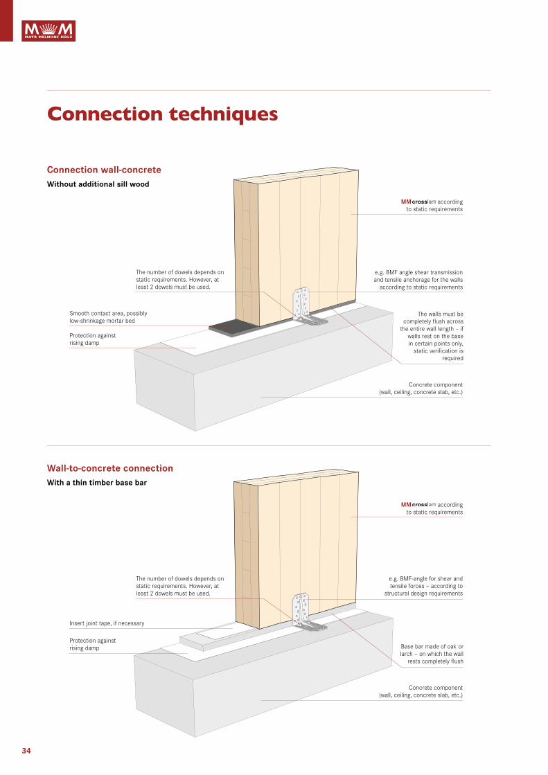
Connection techniques
Connection wall-concreteWithout additional sill wood
according to static requirements
e.g.BMFanglesheartransmission and tensile anchorage for the walls
according to static requirements
Concrete component (wall, ceiling, concrete slab, etc.)
The walls must be completely flush across
the entire wall length – if walls rest on the base in certain points only,
static verification is required
Wall-to-concrete connectionWith a thin timber base bar
Insert joint tape, if necessary
Smoothcontactarea,possibly low-shrinkage mortar bed
Protection against rising damp
Protection against rising damp
according to static requirements
e.g.BMF-angleforshearandtensile forces – according to
structural design requirements
Concrete component (wall, ceiling, concrete slab, etc.)
Basebarmadeofoakorlarch – on which the wall
rests completely flush
The number of dowels depends on static requirements. However, at least 2 dowels must be used.
The number of dowels depends on static requirements. However, at least 2 dowels must be used.

35
Wall-to-wall connection, Wall-to-ceiling-to-wall connectionexternal wall – external wall – ceiling
element joint
Connection techniques
Corner connection – screw connection of the wall corners according to static requirements, joint sealing tapes must be inserted
according to static requirements
according to static requirements
Screwconnectionceilings / walls with self-
tapping wood screws – Type, diameter and distance
(e 30 cm) according to static requirements
e.g.BMFangleforthestaticallyeffective connection between wall
andceiling.Shearforcesinthedirection of the wall, tension and
pressure at right angles to the wall (wind forces)
Joint sealing tapes must be inserted for all panel joints; exemption: external vapour barrier or wind-proofing level
Buttboardrebate
Self-tappingwoodscrewsM8 / e = 25 cm or acc. to static requirements, respectively
Steppedrebate
Self-tappingwoodscrewsM8 / e = 25 cm or acc. to static requirements, respectively

FASC
HIN
GBA
UER
& S
CHA
AR
Your local contact
4 Sawmills4 Timber processing plants2 Pellets production sites3 Briquettes production sites
8 Locations
Russia
Germany
Austria
Czech Republic
Mayr-Melnhof Holz Gaishorn GmbHNr. 182 · 8783 Gaishorn am See · Austria
T +43 3617 2151 0 · F +43 3617 2151 10 · [email protected]
Mayr-Melnhof Holz Gaishorn GmbH Werk Kalwang · Pisching 30 · 8775 Kalwang · Austria
T +43 3846 8181 0 · F +43 3846 8181 29 · [email protected]
Mayr-Melnhof Holz Reuthe GmbH Vorderreuthe 57 · 6870 Reuthe · Austria
T +43 5574 804 0 · F +43 5574 804 201 · [email protected]
Mayr-Melnhof Holz Richen GmbH Römerstraße 20 · 75031 Eppingen-Richen · Germany
T +49 7262 605 0 · F +49 7262 605 35 · [email protected]
www.mm-holz.com
Richen
Reuthe Gaishorn am See
Leoben
Paskov
Frankenmarkt
Kalwang
Vers
ion
2013
/02
Phot
os: m
orge
nste
rn.c
om, k
olle
r-fo
togr
afie
.at,
ww
w.w
alse
rland
.at
ashl
ey-s
tudi
o.co
m, M
ayr M
elnh
of H
olz
Arch
ivBa
ck: g
oess
lers
aile
r.at
Efimovskij