white paper minimizing pim generation from rf cables … · white paper minimizing pim generation...
TRANSCRIPT

White PaPer
Minimizing PiM Generation From rF Cables and Connectors
Understanding mechanical tolerances, coaxial design details
and connector materials used in cable assemblies helps
produce communications equipment with the lowest levels
of passive intermodulation (PIM).

3
Alw
ays
Th
inki
ng
Communications system interference can come in many
forms, but one of the most difficult to defeat is passive
intermodulation (PiM) distortion. Unlike noise, which tends
to cover broad bandwidths and is easily filtered, PiM results in
discrete signals that fall within the operating bandwidth of a
wireless communications receiver, capable of blocking desired
signals. at sufficiently high magnitudes, PiM distortion can
desensitize a communications receiver, resulting in poor quality
of calls in a cellular system or even dropped calls. reliably good
communications system performance depends on minimizing
PiM. and choosing the right cable assemblies can go a long way
towards helping to shave PiM distortion.
What is PiM? it is the result of the nonlinear characteristics of the components and
materials that channel communications signals. it is caused when multiple tones mix
to generate unwanted harmonic signals. Sometimes referred to as “ghost” signals,
these harmonic signals can interfere with the proper operation of a communications
system when they occur at high enough levels. For example, for a wireless cell tower
and its base transceiver station (BtS) attempting to process the very low-level signals
from handheld portable cell phones, unwanted PiM harmonic signals can block the
desired cell-phone signals from ever reaching the cell-tower receiver.
When two signals, f1 and f2, coexist, they can mix and produce third-order, fifth-
order, seventh-order, and higher-order harmonic signal products. the third-order
products are at the highest power levels and are the greatest concern as potential
interference. the other harmonic mixing products decrease in level with increasing
order. third-order PiM products can be produced by a combination of 2f2 – f1 or
2f1 – f2. For example, in the PCS band, cellular communications towers transmit
very strong signals at 1930 to 1990 Mhz and listen for (receive) return signals in the
band from 1850 to 1910 Mhz. the strong transmit signals can generate PiM “ghost”
signals from 1870 to 1910 Mhz [such as 2(1930) – 1990 = 1870 Mhz]. When the
strength of these “ghost” signals rivals the thermal noise floor of the receiver system
(-120 dBm), the receiver can become confused, not being able to tell the difference
between a real phone call signal and a “ghost” signal, resulting in a dropped phone
call and lost communications system capacity. this condition causes frustration for
cell-phone users and lost revenue for cellular service providers.
Wireless communications systems work over a wide dynamic range of signal levels,
often with moderate to extremely low-power signal levels. the noise floor of a BtS is
dependent upon the modulation technique; however, a typical noise floor is generally
-120 dBm. therefore, typical wireless BtS receiver sensitivity is about -110 dBm.
For a cellular
communications
system to operate
effectively, any
unwanted “ghost”
signals such as
PIM signals must be
maintained below
the noise floor of
-120 dBm.
4
Alw
ays
Th
inki
ng
Given that a typical cell phone can transmit signal power levels to about +22 dBm
(about 0.16 W), and assuming a drop in signal level due to free-space path losses for
an average one-mile distance between the cell phone and the BtS antenna tower,
a signal from a cell phone arriving at a cellular tower site may have a power level of
about -109 dBm (about 0.000000000000013 W). For such a cellular communications
system to operate effectively, any unwanted “ghost” signals such as PiM signals must
be maintained below the noise floor of -120 dBm. a cellular BtS that transmits a
downlink signal of +30 dBm (1 W) per channel provides more operating margin at
the receiver than the lower-power handheld cell phone, yielding a lower-level limit of
about -150 dBc, requiring that PiM signal levels be controlled or suppressed to -150
dBc or more, an extremely low signal level by any standard.
PiM is caused by the nonlinear characteristics of different components in a
communications system, and those nonlinear characteristics can stem from the
effects of corona generation, the use of paramagnetic materials, and the effects of
current saturation. Corona generation can occur at high power levels due to sharp
edges at metal-to-metal junctions. although it is not extremely common, it should be
considered as a possibility during the design process for any component intended for
communications system use. Under high-voltage conditions, electrons will congregate
at sharp corners, with the high power levels driving these electrons to the edge of
the electrical junction, causing the dielectric material to become locally ionized. When
tested in a vacuum the corona will display this ionization as a glowing purple light
cloud similar to the Northern Lights. Corona generation can be avoided by developing
rF geometries that support the expected power levels of an application.
Paramagnetic materials exhibit magnetic behavior in an applied aC field. Such
materials should not be used in any components intended for low-PiM communications
applications. Stainless-steel components, silver-clad steel center conductors, and nickel
plating are the most common types of paramagnetic materials in communications
system components. a permanent magnet will not typically attach itself to these
materials, but when an rF signal is applied to a paramagnetic material, the same type
of hysteresis is developed which can initiate PiM harmonics. Care must also be taken
when considering sources of brass, as impurities within the brass can promote PiM
generation. this has been particularly troublesome to manufacturers of magnetic-
resonant-imaging (Mri) equipment, where any paramagnetic impurities can hinder
proper performance. in fabricating components for minimal PiM in communications
systems, some of the safe materials to choose are brass, phosphor bronze, beryllium-
copper (BeCu), aluminum, silver, gold, and albaloy (white bronze plating), using
certified aStM specified materials whenever possible.
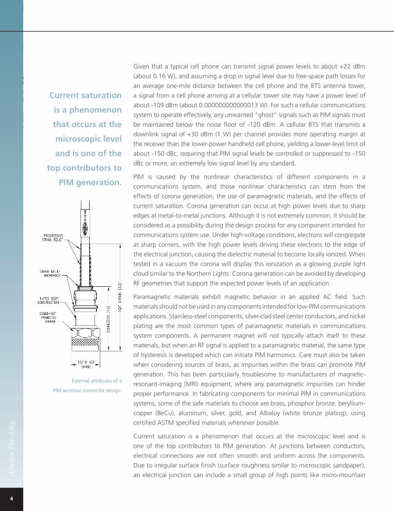
Current saturation is a phenomenon that occurs at the microscopic level and is
one of the top contributors to PiM generation. at junctions between conductors,
electrical connections are not often smooth and uniform across the components.
Due to irregular surface finish (surface roughness similar to microscopic sandpaper),
an electrical junction can include a small group of high points like micro-mountain
Current saturation
is a phenomenon
that occurs at the
microscopic level
and is one of the
top contributors to
PIM generation.
external attributes of a
PiM sensitive connector design.
5
Alw
ays
Th
inki
ng
tops. as a result, the current flow is not distributed efficiently and evenly across the
mating components. however, with additional mating force between these surfaces,
the micro-mountain tops can be partially flattened to increase the contact surface
area and reduce current saturation within the junction or connection. this can help
minimize or negate the generation of PiM.
Oxide layers that develop on plating surfaces of mating components can also impact
current saturation. these oxides establish an insulating layer between conductors
that results in reduced surface area for current flow. through the use of material
combinations of hard and soft materials with strong wiping action between mating
surfaces, the action of mating these components can break down the oxide barriers,
establish an improved connection, and further negate PiM generation.
the use of coaxial cable assemblies with braids can present challenges when
attempting to achieve low PiM performance in a communication system. When such
cables undergo flexure, the braids rub over each other and are constantly repositioning
themselves. Because of such dynamic conditions, ground currents are continuously
being rerouted through the fine braids, presenting opportunities for current saturation
and non-transverse-electromagnetic (non-teM) modes or eddy currents within the
cable braid structure. although this is not fully modeled, evidence of this effect is
apparent during vibration testing of cables while measuring PiM levels.
For example, consider evaluations of three different cable types terminated in industry
standard type N plugs. an rG-400 coaxial cable has a dual braid structure of woven
round conductors. Under a static condition, this cable will support PiM performance
of -145 dBc. But during vibration, this type of cable becomes unstable and the PiM
performance drops to -90 dBc. When the vibration is removed, the PiM performance
returns to -145 dBc. another braided cable type, flexible-141, has a flat ribbon braid
followed by a woven round over braid. When tested under a static condition, it
supports PiM performance of -155 dBc. Under vibration, the PiM performance drops
to -148 dBc. When the vibration is removed, the PiM performance returns to -155
dBc. a third braided cable type, tCOM-240, has a flat ribbon braid, followed by an
intermediate foil, followed by a woven round overbraid. tested under a static condition,
the PiM performance is -155 dBc. With vibration, the cable remains extremely stable,
with PiM performance degrading only to -153 dBc. Once the vibration is removed, the
PiM performance returns to a level of -155 dBc. as these three examples show, braid
structure is extremely important to the development of low-PiM system integration
and one of the more critical elements in designing and deploying reliable, robust
cellular communications sites.
Minimizing current saturation is one key to minimizing PiM generation in coaxial
cable assemblies. Some of the design considerations for minimizing current saturation
include fabricating smooth surface finishes, using single-body constructions and, when
multiple-body constructions are required, to not use threads. Use heavy press fits for pins
and sockets to maximize the number of socket tines to increase the number of contact
points. also important is the choice of high-quality, engineered cables. to support these
Minimizing current
saturation is one key
to minimizing PIM
generation in coaxial
cable assemblies.

6
Alw
ays
Th
inki
ng
efforts, San-tron has developed a suite of low PiM cable assemblies called SrXtM cables
to support system integrators. Seven different deployment scenarios encompassing
cabinet integration, short cable runs or jumper applications, long haul cable runs, indoor
use, outdoor use, riser, and plenum environments have been accommodated for. as an
example, for in-cabinet and plenum-rated deployments, low-PiM SrX cable assembly
solutions are formed through the combination of eSMa and eSeries connectors
and flexible-141, conformable-141, and semirigid rG-402 cables.
the flexible-based solutions support plenum-rated deployments to 150 W at 2.5 Ghz.
these assemblies exhibit attenuation of 22 dB per 100 ft., with bend radius of 0.2
in. they can handle operating temperatures to +125°C. raw flexible-141 cables are
specified for PiM level of -150 dBc although they have been characterized with typical
PiM levels of better than -157 dBc. these cables are light in weight, two of them are
flexible, and they support the integration of subsystems and in-cabinet deployments.
For short runs and jumper applications requiring highly flexible, robust assemblies
(such as in indoor and outdoor use, risers, and in plenum deployments), San-tron has
developed a unique solution for the clamp-type termination of low-PiM cable assemblies
to braided, flexible coaxial cables. Basic deployment based on tCOM-240 cable
supports power levels to 160 W at 2.5 Ghz with attenuation of 13 dB per 100 ft. and
bend radius of 2.5 in. these assemblies can handle operating temperatures to +85°C
with PiM performance of -155 dBc that is stable with vibration within a 2 dB window.
For flame-retardant requirements assemblies employ tCOM-240-Fr cables, while for
plenum-rated installations, assemblies feature SFt-205 cables with a temperature rating
to +165°C.
For long-haul runs requiring robust, low-loss deployments (such as in indoor and
outdoor in stations, in risers, and in plenum deployments), San-tron has developed
a technique that sets extremely low and stable PiM levels and supports continuous
bending and flexure. Basic deployment with tCOM-400 cable supports power levels
to 310 W at 2.5 Ghz with low attenuation of 7 dB per 100 ft. and a bend radius of 4
in. these assemblies, which are rated to operating temperatures to +85°C, also exhibit
PiM performance of -155 dBc that is stable with vibration within a 2 dB window.
For flame-retardant requirements assemblies employ tCOM-400-Fr cables, while for
plenum-rated installations, assemblies feature SFt-393 cables with a temperature
rating to +165°C.
in conclusion, the use of San-tron’s SrX coaxial cable assemblies offers deployment
advantages when low PiM levels are critical. eSMa series connectors control PiM to
less than -153 dBc at frequencies to 20 Ghz, while eSeries type 7/16 connectors
operate through 8 Ghz with PiM levels of -174 dBc or less. SrX cable assemblies
manufactured with these connectors and tCOM and SFt cables support performance
through 6 Ghz with PiM of less than -155 dBc. SrX low-PiM cable assemblies are
available in standard lengths as well as custom configurations (contact factory).
Notes: TCOM and SFT are trademarks of Times Microwave Systems, Wallingford, CT. SRX, eSMA and eSeries are trademarks of San-tron, Inc.
San-tron’s SRX
coaxial cables
offer deployment
advantages when
low PIM levels
are critical.
San-tron’s SrX
cable assemblies are designed with
numerous details that result in
outstanding PiM performance,
even with changing
environmental conditions.
PiM performance of tCOM-240/N-plugs/ 1 meter under vibration
PiM performance of flexible-141/eSeries N-plugs/1 meter under and after vibration

7
Alw
ays
Th
inki
ng
a sampling of San-tron’s SrX low-PiM cable assemblies.
Description Frequency (GHz) PIM (dBc) Model
SrX Cabinet Cables (Flexible-141, Conformable-141, Semirigid)
eSeries N Plug – Straight 20 -155 0401-257-aS
eSeries N Plug – right angle 12.4 -155 0402-79-aS
eSeries N Jack – Straight 18 -155 0403-74-aS
eSeries N Jack – Bulkhead with Gasket 18 -155 0405-72-aS
eSeries tNC Plug – Straight – reverse Polarity 6 -140 0501-75-aG
eSeries tNC Plug – right angle – reverse Polarity 6 -140 0502-17-aG
eSMa Plug – Straight 20 -153 1201-28-aG
eSMa Plug – Straight – reverse Polarity 20 -153 1201-45-aG
eSMa Plug – right angle 12.4 -153 1202-42-aG
eSMa Jack – Straight 20 -153 1203-08-aG
eSMa Jack – Panel 20 -153 1204-06-aG
eSMa Jack – Bulkhead 20 -153 1205-06-aG
eSMa Jack – Bulkhead with O ring 20 -153 1205-07-aG
eSeries 7/16 Plug – Straight 8 -174 1901-24-aS
eSeries 7/16 Jack – Panel with O ring 8 -174 1904-05-aS
eSeries 7/16 Jack – Bulkhead with O ring 8 -174 1905-06-aS
SrX Jumper Cables (tCOM-240, tCOM-240-Fr, SFt-205)
type N Plug – Straight 6 -155 0401-279-USa
type N Jack – Straight 6 -155 0403-73-US
type N Jack – Bulkhead with Gasket 6 -155 0405-ii-US
tNC Plug – Straight – reverse Polarity 6 -155 0501-ii-USa
7/16 Plug – Straight 6 -155 1901-30-USa
7/16 Plug – right angle 6 -155 1902-ii-USa
7/16 Jack – Bulkhead with O ring 6 -155 1905-ii-US
SrX Long haul Cables (tCOM-400, tCOM-400-Fr, SFt-393)
type N Plug – Straight 6 -155 0401-288-USa
type N Jack – Straight 6 -155 0403-75-US
type N Jack – Bulkhead with Gasket 6 -155 0405-ii-US
tNC Plug – Straight – reverse Polarity 6 -155 0501-ii-USa
7/16 Plug – Straight 6 -155 1901-ii-USa
7/16 Plug – right angle 6 -155 1902-ii-USa
7/16 Jack – Bulkhead with O ring 6 -155 1905-ii-US
Note: Connectors appearing in red are in development and planned for release in the near future.

San-tron, inc.
FreD hULL
Director of engineering
4 turnpike road
ipswich, Ma 01938
(978) 356-1585
www.santron.com
Always Thinking