white paper wp083023en ac vs. dc coupling in utility-scale
TRANSCRIPT

January 1999
Cutler-Hammer
CAT.71.01.T.E
E
E3-1Low-Voltage Switchgear and SwitchboardsLow-Voltage Distribution Switchboards
General Description
Type 1 – Pow-R-Line C Front Accessible Group Mounted Feeders
See page E3-5 for description.
Type 1 – Layout Data For a Front Accessible Group Mounted Feeder Cutler-Hammer Switchboard
Step 1
➀
Layout incoming main section (with or without main device) as follows:Special Utility Metering CompartmentWest Coast Utility Metering CompartmentStandard NEMA Utility Metering CompartmentCustomer Only Metering CompartmentNo Metering Compartment
Page E3-7Page E3-11Page E3-13Page E3-14Page E3-14
Step 2 Layout Feeder DevicesPow-R-Line C Group Mounted Type
Individually Mounted TypeOPTIM Devices
Page E3-15Page E3-18Page E3-19
Step 3 Technical data, e.g., interrupting ratings, terminal size, and optional TVSS ratings. Page E3-59
Step 4 Specification Data Page E3-63
Type 2 – Pow-R-Line C Rear Accessible Group Mounted Feeders
See page E3-23 for description.
Type 2 – Layout Data For a Rear Accessible Group Mounted Feeder Cutler-Hammer Switchboard
Step 1
➀
Layout incoming main section (with or without main device) as follows:Special Utility Metering CompartmentWest Coast Utility Metering CompartmentStandard NEMA Utility Metering CompartmentCustomer Only Metering CompartmentNo Metering Compartment
Page E3-25Page E3-29Page E3-31Page E3-32 Page E3-32
Step 2 Layout Feeder DevicesPow-R-Line C Group Mounted Type
Individually Mounted TypeOPTIM Devices
Page E3-33Page E3-36Page E3-37
Step 3 Technical data, e.g., interrupting ratings, terminal size, and optional TVSS ratings. Page E3-59
Step 4 Specification Data Page E3-63
Type 3 – Pow-R-Line
i
Rear Accessible Compartmentalized Mounted Feeders
See page E3-41 for description.
Type 3 – Layout Data For a Rear Accessible Compartmentalized Cutler-Hammer Switchboard
Step 1
➀
Layout incoming main section (with or without main device) as follows:Special Utility Metering CompartmentWest Coast Utility Metering CompartmentStandard NEMA Utility Metering CompartmentCustomer Only Metering CompartmentNo Metering Compartment
Page E3-44Page E3-48Page E3-50Page E3-51Page E3-51
Step 2 Layout Feeder DevicesPow-R-Line
i
Compartmentalized TypeIndividually Mounted Type
➁
OPTIM Devices
Page E3-52Page E3-54Page E3-55
Step 3 Technical data, e.g., interrupting ratings, terminal size, and optional TVSS ratings. Page E3-59
Step 4 Specification Data Page E3-65
➀
Since utility compartment dimensions are the minimum required by utility, check “no metering” main device widths and use the larger width of
either the main device or utility metering compartment.
➁
Individually mounted feeders are individually mounted, not compartmentalized.

CAT.71.01.T.E
Cutler-Hammer
January 1999
E
E3-2 Low-Voltage Switchgear and SwitchboardsLow-Voltage Distribution Switchboards
General Description
Application Considerations and Definitions
Pow-R-Line designates a family of distribu-tion switchboards incorporating new design concepts that fit the ever-increasing need for applications on high short-circuit systems, while retaining maximum standardization, safety and convenience throughout the line.
Front Accessibility
Front accessibility switchboards align at the rear, enabling them to be placed against a wall (Cutler-Hammer Type Pow-R-Line C front accessible). If the main section is deeper than others, due to physical size of the main device, the necessary off-set in line up will occur in front, and the main section will be accessible from the side as well as from the front. Cutler-Hammer also offers front ac-cessible switchboards that align at the front and rear.
Rear Accessibility
Rear accessible switchboards align at the front and the rear. Bus maintenance and cable entry and exit require rear access. There are two types of rear accessible switch-boards. Both types utilize the same incoming utility and/or main structures. The first type utilizes group mounted feeder devices with panel construction (Cutler-Hammer Type Pow-R-Line C rear accessible). The second type utilizes individually compartmentalized feeder devices with load side insulated bus bar extensions (Cutler-Hammer Type Pow-R-Line
i
).
Standard Switchboard Height
Standard Pow-R-Line switchboard height is 90 inches.
Group Mounting
Group mounted circuit protective devices are an assembly of units mounted on a panel-board type base (panelboard construction). Units may be molded case breakers, or FDPW fusible switches. Circuit protective devices are accessible from the front.
A main molded case breaker or main FDPW fusible switch, within the sizes listed for pan-elboard design, can be included in the panel mounted assembly in lieu of a separate, individually mounted unit.
Space Only for Future Devices Group Mounted Construction
Where space only for future circuit protective devices is required, the proper space and a blank filler plate will be supplied. Connections and mounting hardware are not included.
Provision for Future Devices
Where provisions for future circuit protective devices are required, space for the device, corresponding vertical bus, device connec-tors and the necessary mounting hardware will be supplied.
Bus Bar System
Standard bus in the switchboards is tin-plated aluminum. Copper and silver-plated copper are also available.
Main bus and sub-main busses meet UL and NEMA standards for temperature rise on all Pow-R-Line switchboards. Special bus densities are available.
Overcurrent Devices
To properly select and size overcurrent devices for use in a switchboard, the allowable tem-perature rise must be taken into account as to its effect on the tripping characteristics of the devices in question.
Accordingly, Article 220-4(a) of the NEC requires overcurrent devices to be rated not less than 125% of the continuous load they are protecting. To comply with this, an 80% derating factor must be used with all overcur-rent devices such as molded case breakers and FDPW fusible switches unless they are tested and approved for application at 100% of the rating.
Short Circuit Rating
Standard bus and connectors on all switch-boards are rated for use on Systems capable of producing up to 65,000 amperes rms sym-metrical short circuit current at the incoming terminals.
Increased bus short circuit ratings equal to that of connected switchboard devices, up to 200,000 amperes rms symmetrical, are avail-able in most Pow-R-Line switchboards when approved main devices are installed. Contact Cutler-Hammer for more information. UL labeled switchboard sections are marked with their applicable short circuit rating.
Provision for Busway Entrance and Exit
Busway connections to switchboard sections include cutout and drilling in the top of the switchboard with riser connections from the switchboard device or bus, up to the point where the bus duct enters the switchboard. No connections are furnished external to the switchboard.
In all transactions involving busway attached to switchboards, it is essential that information regarding orientation of the busway with respect to the front of the switchboard be supplied to the coordinatingassembly plant.
On Pow-R-Line switchboards, solid bus bar is used to connect the bus duct to the individu-ally mounted main device, main or sub-main switchboard bus, or vertical main bus of panel mounted circuit protective device panels.
Busway fed by group mounted branch devices are cable connected.
Aluminum riser connections are standard. Copper- or silver-plated copper is available as a modification.
Transitions
Transition structures are required for con-necting switchboards to the secondary of power center transformer (dry or fluid filled), motor control centers, and for other special switchboard configurations such as “L” or “U” shaped lineups. In some application, an extra structure complete with connections is required; in others, where switchboard depth and space permit, only the connection conductors are required. (Refer to factory for these applications.)
Auxiliary Structures
These are normally mounted adjacent to service structures or distribution structures and used where incoming service or feeder conductors require additional space or facilities not included in the standard switchboard, such as:
1. Mounted adjacent to a top connected service structure and used as a cable pull structure where service conductors are brought in underground. Auxiliary struc-tures are the same depth and height as the service structure, and are wide enough to accommodate the incoming cables.
2. Mounted adjacent to a service structure and used as a bus transition compart-ment for running riser bus from the load-side of the service structure up to top outgoing bus duct connection when distribution structures are not required. Auxiliary structures are the same depth and height as service structures.
In addition to the above applications, auxiliary structures may be mounted adjacent to a dis-tribution structure and used as a structure for lighting panel or other device which may be cable-connected to a branch circuit device in the distribution structure. Dimensions are compatible with arrangements required.
Switchboards Used as Service Equipment
Service equipment is the electrical equip-ment that constitutes the main control and means of power cutoff the electric service (normally power company supply) brought into the building.
Where switchboards are to be used as service equipment, certain NEC and UL requirements apply that necessitate modifications not normally supplied in switchboards.
The following is a summary of the require-ments which are pertinent to the application of a switchboard for service equipment:
c. A switchboard with main lugs only (no main disconnect) must be designed so that all circuits in the switchboard can be disconnected from the supply source by the operation of no more than six operating handles (breaker or switch).
Further Information
CAT.73.01.T.E

January 1999
Cutler-Hammer
CAT.71.01.T.E
E
E3-3Low-Voltage Switchgear and SwitchboardsLow-Voltage Distribution Switchboards
General Description – Optional Devices
IQ Analyzer
See section B1.
IQ DP-4000
See section B1.
Assemblies Electronic Monitor II
See section B4.
Power Line Analyzer
The IQ Analyzer is a complete solution for users who want to monitor all aspects of their electrical distribution system. Its high perfor-mance metering complies with the rigid ANSI C12.16 Class 10 accuracy specification for revenue meters, provides quality true RMS readings through the 50th harmonic, accu-rately measures nonsinusoidal wave forms up to a 3.0 crest factor, and displays even and odd multiples of the fundamental current and voltage through the 50th harmonic.
Features include:
●
Over 150 continuously metered parameters.
●
Displays multiple parameters at the same time (up to 7 lines of information on one screen).
●
Programming and access to all informa-tion via the faceplate.
●
Remote communications capability within an IMPACC/PowerNet system.
Incoming Line Metering and Voltage Protection
This microprocessor-based device provides complete metering and system voltage pro-tection. It replaces individually mounted and wired ammeters, voltmeters, ammeter and voltmeter switches, wattmeters, varmeters, and watthour meters.
IQ DP-4000 features include:
●
Cost and space savings through replace-ment of individual meters and switches.
●
Direct voltage input of up to 600 volts – no additional PTs required.
●
Voltage protection set by customer replaces: undervoltage relay, overvoltage relay, phase loss relay, and phase unbalance relay.
●
Nonvolatile memory
●
Remote communications capability avail-able within an IMPACC/PowerNet System.
Centralized Monitoring and Information Display
This microprocessor-based device monitors up to 40 circuit breakers with Digitrip RMS 700, RMS 800, RMS 810, and RMS 910 Trip Units; and displays status, cause of trip, and metered values (including current at time of trip) from each circuit breaker. The device can also receive and transmit data from eight IQ Data Plus II and/or IQ Data devices.
Assemblies Electronic Monitor II features include:
●
Local or remote monitoring.
●
Separate metering transformers are not required.
●
Remote communications capability avail-able within an IMPACC/PowerNet System.
●
A centralized alternative to ammeters and ammeter switches, circuit breaker position indicating lights, and alarm contacts.
●
Nonvolatile memory.
IQ 200
See section B1.
Addressable Relay II
See section B5.
Voltage and Current Metering
This microprocessor-based device performs voltage, current, power and energy metering functions.
IQ 200 features include:
●
Separate voltage and ammeter windows. Voltage and current can be stepped through independently.
●
Auto ranging between volts and kilovolts, and amps and kiloamps.
●
Remote communications capability avail-able within an IMPACC/PowerNet System.
Direct On/Off Control Capabilities
An industrial control relay with two inputs to monitor the status of external contacts and one output controllable over the communica-tion network. The relay is ac/dc powered with ac/dc contacts rated to directly switch/monitor switchgear breakers, motor starters, etc.
Addressable features include:
●
Address assigned by setting three hexadecimal switches.
●
LEDs show when the relay is energized and when it is sending reports.
●
Two status inputs and a Form C contact output.
●
Built in remote communications capability within an IMPACC/PowerNet System.
●
Selectable baud rate.
Communications
For remote power monitoring and soft-ware see IMPACC/PowerNet section B5.
Centralized Monitoring and Information Display
The Breaker Interface Module is a panel-mounted device which performs the follow-ing functions:
●
Monitors and displays parameters from any combination of Digitrip RMS 810 and 910, Digitrip OPTIM Trip Units, F/J/K Frame Energy Sentinels, and Universal Energy Sentinels, supporting as many as 50 of these devices up to 10,000 feet away.
●
Communicates the information from these protective and energy monitoring devices over an IMPACC/PowerNet net-work to a computer or PLC.
Breaker Interface Module (BIM)
See section B4.
CAT.71.01.T.E
Cutler-Hammer
January 1999
E
E3-4 Low-Voltage Switchgear and SwitchboardsLow-Voltage Distribution Switchboards
General Description – IQ Energy Sentinel/Electronic RMS Trip Units
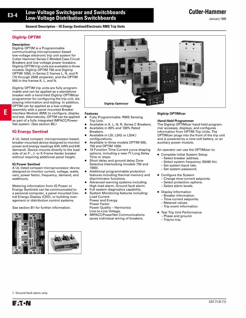
Digitrip OPTIM
Description
Digitrip OPTIM is a Programmable communicating microprocessor-based low-voltage electronic trip unit system for Cutler-Hammer Series C Molded Case Circuit Breakers and low-voltage power breakers. Digitrip OPTIM trip units are available in three models: Digitrip OPTIM 750 and Digitrip OPTIM 1050, in Series C frames L, N, and R (70 through 2500 amperes), and the OPTIM 550 in the frames K, L, and N.
Digitrip OPTIM trip units are fully program-mable and can be applied as a standalone breaker with a hand-held Digitrip OPTIMizer programmer for configuring the trip unit, dis-playing information and testing. In addition, OPTIM can be applied as a low-voltage assembly with a panel mounted Breaker Interface Module (BIM) to configure, display and test. Alternatively, OPTIM can be applied as part of a fully integrated IMPACC/Power-Net system. (See section B5.)
IQ Energy Sentinel
A UL listed compact, microprocessor-based, breaker mounted device designed to monitor power and energy readings (kW, kWh and kW demand). Device mounts directly to the load side of an F-, J- or K-Frame feeder breaker without requiring additional panel height.
IQ Power Sentinel
A UL listed compact microproccessor device designed to monitor current, voltage, watts, vars, power factor, frequency, demand, and watthours.
Metering information from IQ Power or Energy Sentinels can be communicated to a personal computer, a panel mounted Cen-tral Energy Display (CED), or building man-agement or distribution control systems.
See section B1 for further information.
Features
●
Fully Programmable. RMS Sensing Trip Unit.
●
Available in K, L, N, R, Series C Breakers.
●
Available in 80% and 100% Rated Breakers.
●
Available in LSI, LSIG or LSIA
➀
configurations.
●
Available in three models OPTIM 550, 750 and OPTIM 1050.
●
10 Function Time-Current curve shaping options, including a new I
4
t Long Delay Time or slope.
●
Short delay and ground delay Zone Selective Interlocking (models 750 and 1050).
●
Additional programmable protection features including thermal memory and discriminator functions.
●
Advanced warning systems including High load alarm, Ground fault alarm.
●
Full system diagnostics capability.
●
System Monitoring features including:Load CurrentPower and EnergyPower FactorPower Quality – HarmonicsLine-to-Line Voltage.
●
IMPACC/PowerNet Communications saves individual wiring of breakers.
➀
Ground fault alarm only.
Digitrip OPTIMizer
Hand-Held Programmer
The Digitrip OPTIMizer hand-held program-mer accesses, displays, and configures information from OPTIM Trip Units. The OPTIMizer plugs into the front of the trip unit and is powered by a nine-volt battery, or an auxiliary power module.
An operator can use the OPTIMizer to:
●
Complete Initial System Setup– Select breaker address.– Select system frequency (50/60 Hz).– Set system baud rate.– Set system password.
●
Configure the System– Change time-current setpoints.– Select protection options.– Select alarm levels.
●
Display Information– Breaker information.– Time-current setpoints.– Metered values.– Trip event information.
●
Test Trip Unit Performance– Phase and ground.– Trip/no trip.
Digitrip Optimizer

January 1999
Cutler-Hammer
CAT.71.01.T.E
E
E3-5Low-Voltage Switchgear and SwitchboardsLow-Voltage Distribution Switchboards
Type 1 Layout Information – Front Accessible, Group Mounted Feeder Devices
Type 1Pow-R-Line C Switchboards
Meets NEMA Standard PB-2 and UL 891.
Construction Details
●
6000 Ampere Main Bus Maximum.
●
Front accessible – Main sections front and/or side accessible.
●
Feeder devices group mounted.
●
Sections rear aligned or front and rear aligned.
●
Designed for mounting against a wall, but self-supporting, or with code clearance to a wall.
Main Devices, Individually Mounted
●
Molded Case Circuit Breaker, 400-2500 Amperes, fixed or draw-out.
●
Air Power Circuit Breaker; DS
and Magnum DS, 800-5000 Amperes, fixed or draw-out.
●
Air Power Circuit Breaker with Current Limiting Fuses, DSL, 800-5000 Amperes.
●
Bolted Pressure Switch, 800-6000 Amperes, fixed.
●
Fusible Switches; FDPW, 400-1200 Amperes, fixed.
Feeder Devices, Group Mounted
●
Molded Case Circuit Breakers, 15-1200 Amperes.
●
Fusible Switches; FDPW, 30-1200 Amperes.
Feeder Devices, Individually Mounted
●
Air Power Circuit Breakers, DS and Magnum DS, 800-2500 Amperes.
●
Bolted Pressure Switches, 800-1600 Amperes, fixed.
CAT.71.01.T.E
Cutler-HammerJanuary 1999
E
E3-6 Low-Voltage Switchgear and SwitchboardsLow-Voltage Distribution SwitchboardsType 1 Layout Information – Front Accessible, Group Mounted Feeder Devices
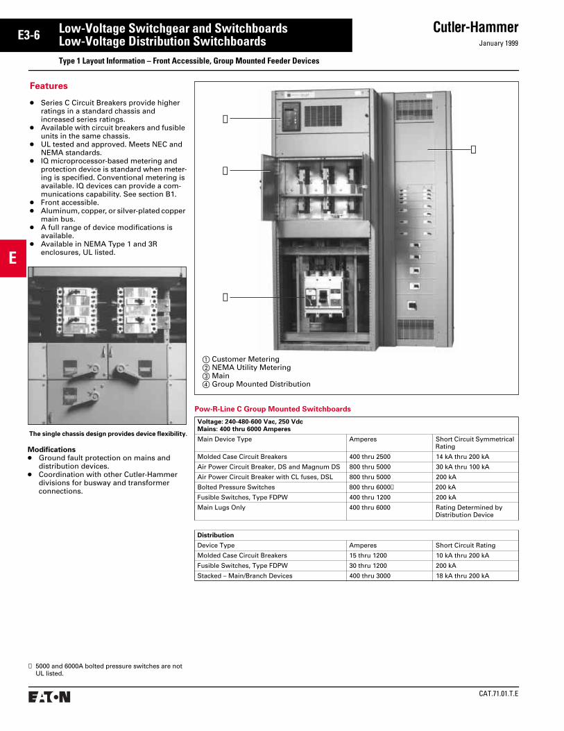
The single chassis design provides device flexibility.
Features
● Series C Circuit Breakers provide higher ratings in a standard chassis and increased series ratings.
● Available with circuit breakers and fusible units in the same chassis.
● UL tested and approved. Meets NEC and NEMA standards.
● IQ microprocessor-based metering and protection device is standard when meter-ing is specified. Conventional metering is available. IQ devices can provide a com-munications capability. See section B1.
● Front accessible.● Aluminum, copper, or silver-plated copper
main bus.● A full range of device modifications is
available.● Available in NEMA Type 1 and 3R
enclosures, UL listed.
Pow-R-Line C Group Mounted Switchboards
Voltage: 240-480-600 Vac, 250 VdcMains: 400 thru 6000 Amperes
Main Device Type Amperes Short Circuit Symmetrical Rating
Molded Case Circuit Breakers 400 thru 2500 14 kA thru 200 kA
Air Power Circuit Breaker, DS and Magnum DS 800 thru 5000 30 kA thru 100 kA
Air Power Circuit Breaker with CL fuses, DSL 800 thru 5000 200 kA
Bolted Pressure Switches 800 thru 6000➀ 200 kA
Fusible Switches, Type FDPW 400 thru 1200 200 kA
Main Lugs Only 400 thru 6000 Rating Determined by Distribution Device
Distribution
Device Type Amperes Short Circuit Rating
Molded Case Circuit Breakers 15 thru 1200 10 kA thru 200 kA
Fusible Switches, Type FDPW 30 thru 1200 200 kA
Stacked – Main/Branch Devices 400 thru 3000 18 kA thru 200 kA
a Customer Meteringb NEMA Utility Meteringc Maind Group Mounted Distribution
➃
➀
➁
➂
Modifications● Ground fault protection on mains and
distribution devices.● Coordination with other Cutler-Hammer
divisions for busway and transformer connections.
➀ 5000 and 6000A bolted pressure switches are not UL listed.

January 1999
Cutler-Hammer
CAT.71.01.T.E
E
E3-7Low-Voltage Switchgear and SwitchboardsLow-Voltage Distribution SwitchboardsType 1 Layout Dimensions – Front Accessible, Group Mounted Feeders Pow-R-Line C
W or W1
ClearArea
➇
33
21⁄2
21⁄2
D
Blank
UtilityCompartmentHot Sequence
WD
●
●
BlankPull
Section
UtilityCompartmentHot Sequence
WD
PullSection
UtilityCompartmentHot Sequence
Main
WD
●
W1
HPull Box
PullSection
Main2500AmpMax.➄
WD
W1
HPull Box
UtilityCompartment
ColdSequence
Main Structure – With Special Utility CT Compartments and/or Main Devices
Dimensions (inches) for Estimating Purposes Only.
Dimensions for Figures 1-4 “W” or “D” of structure is determined by the dimensions of the utility compartment or main device – whichever is greater. For main device dimensions see page E3-14. N/A = Not Applicable
Power CompanyCompartments
MeteringSequence
Front Accessible
Figure 1 Figure 2 Figure 3 Figure 4 Top MtdPull Box
PullSection
W D D D D H W1
Atlantic City Electric Hot Bottom Top
800A1200A1600-2000A2500-4000A
36364545
30303636
30303636
30303636
24243636
N/AN/AN/AN/A
N/AN/AN/AN/A
20262630
Baltimore Gas and Electric➆ Hot
800A1200-2500A3000-4000A
36/45➆36/45➆45➆
36/30➆36/30➆30➆
36/30➆36/30➆30➆
N/AN/AN/A
N/AN/AN/A
N/AN/AN/A
N/AN/AN/A
Boston Edison Cold
800-1600A2000-2500A3000-4000A
363636➄
N/AN/AN/A
N/AN/AN/A
N/AN/AN/A
303636➄
1824N/A➄
2630N/A
Central Hudson Gas and Electric Hot➉/Cold ➅ ➅ ➅ ➅ ➅ N/A ➅
Central Vermont Hot ➅ ➅ ➅ ➅ ➅ N/A ➅
Cincinnati Gas and Electric Hot Bottom Top
800A1000A1200-2000A2500-4000A
36364545
30303636
30303636
30303636
24243636
N/AN/AN/AN/A
N/AN/AN/AN/A
20262630
Commonwealth Edison Hot Bottom Top
400-1000A1200-2000A2500-4000A
363636
303636
303636
303636
303636
N/AN/AN/A
12➈1824
202630
Bottom Feed Top Feed Bottom or Top Feed Bottom or Top Feed
Figure 1. Figure 2. Figure 3. Figure 4. (Cold Sequence)
Floor PlanFigures 1., 3. and 4.Pull Section Only
➀ Refer to Cutler-Hammer.➁ For limiter lugs or more than six (6) mechanical
lugs per phase, use Fig. 3.➂ For limiter lugs or more than six (6) mechanical
lugs per phase, a 12-inch pull box is required.➃ For bottom incoming, front accessible applica-
tions only, 45-inch wide pull section required.➄ Cold sequence: 3000A or 4000A main device must
be mounted in separate structure. Refer to page E3-14, Figs. 1 and 2. The utility compartment will
then be housed in the second structure. Branch devices or customer metering can then be mounted in remaining half of utility compartment structure.
➅ Dimensions are the same as standard NEMA utility compartments, refer to page E3-13.
➆ For BG&E, the utility compartment is mounted in the bottom for Fig. 1 and top for Fig. 2. For bottom feed (Fig. 1); up to 2500 amperes, the main is mounted in top. For 3000A and 4000A bottom feed, the main is in a separate structure. For top
feed (Fig. 2), maximum amperes is 4000A and the main is mounted in the bottom.
➇ Clear area assumes no floor channels used under bottom frame.
➈ Only required for 750 kcmil incoming cables.➉ For special applications approved by the utility.k Clearance from walls (on boards that are not rear
accessible) should be a minimum of 1/2 inch for indoor boards. For boards used in outdoor orwet locations the clearance should be no lessthan 6 inches.

CAT.71.01.T.E
Cutler-HammerJanuary 1999
E
E3-8 Low-Voltage Switchgear and SwitchboardsLow-Voltage Distribution SwitchboardsType 1 Layout Dimensions – Front Accessible, Group Mounted Feeders Pow-R-Line C
Main Structure – With Special Utility CT Compartments and/or Main Devices, Continued
Dimensions for Figures 1-4, Continued, “W” or “D” of structure is determined by the dimensions of the utility compartment or main device – whichever is greater. For main device dimensions see page E3-14. N/A = Not Applicable
Power CompanyCompartments
MeteringSequence
Front Accessible
Figure 1 Figure 2 Figure 3 Figure 4 Top MtdPull Box
PullSection
W D D D D H W1
Connecticut Light and Power Hot➉/Cold
800-1200A1600-2000A2500-4000A
➅3636/45
➅3036
➅3036
➅3036
➅3036➄
N/A1824➄
➅2630
Consolidated Edison Hot Bottom Top
800A (Spec. 298)1200-1600A (Spec. 298) 1200-2000A (Spec. 377)2500-4000A (Spec. 377)
38384545
24243636
24➀24➀36➀36➀
24243636
24243636
N/AN/AN/AN/A
12 (Fig. 3)12 (Fig. 3)1824
202626 (48D)30 (48D)
Detroit Edison Hot Bottom Top
800A1200-2000A2500-4000A
363645
303036
303036
303036
303036
N/AN/AN/A
N/AN/AN/A
202630
Florida Power and Light Hot ➅ ➅ ➅ ➅ ➅ ➅ N/A ➅
Georgia Power Co. Hot ➅ ➅ ➅ ➅ ➅ ➅ N/A ➅
Indianapolis Power Co. Hot/Cold➉ Bottom Top
800A1200-2000A2500-4000A
363636
363636
363636
363636
363636
303636➄
121824➄
262630
Jersey Central Power Hot➉/Cold Bottom Top
800A1200-2000A2500-4000A
➅4545
➅3636
➅3636
➅3636
➅3636
➅3636
N/A1824
➅2630
Kansas City Power and Light Hot ➅ ➅ ➅ ➅ ➅ N/A ➅
Long Island Light Co. Hot Bottom Top
800-1200A1600-2000A2500-4000A
384545
243636
243636
243636
243636
N/AN/AN/A
N/A1824
202630
Louisville Gas and Electric Hot Bottom Top
800A1200-2000A2500-3000A
364545
363636
363636
363636
303636
N/AN/AN/A
121824
202630
Madison Gas and Electric Cold Bottom Top
800-1200A1600-2000A2500-4000A
363645
N/AN/AN/A
N/AN/AN/A
N/AN/AN/A
N/AN/AN/A
303036➄
121818➄
202630➄
Massachusetts Electric Hot Bottom Top
800A1200-2000A2500-4000A
➅3636/45
➅3036
➅3036
➅3036
➅3036
N/AN/AN/A
N/AN/AN/A
➅2630
Metropolitan Edison Hot ➅ ➅ ➅ ➅ ➅ N/A ➅
Monongahela Power Hot ➅ ➅ ➅ ➅ ➅ ➅ N/A ➅
Naperville Hot ➅ ➅ ➅ ➅ ➅ N/A ➅
Narragansett Hot Bottom Top
800A1200-2000A2500-4000A
➅3636/45
➅3036
➅3036
➅3036
➅3036
N/AN/AN/A
N/AN/AN/A
➅2630
Dimensions (inches) for Estimating Purposes Only.
➀ Refer to Cutler-Hammer.➁ For limiter lugs or more than six (6) mechanical
lugs per phase, use Fig. 3.➂ For limiter lugs or more than six (6) mechanical
lugs per phase, a 12-inch pull box is required.➃ For bottom incoming, front accessible applica-
tions only, 45-inch wide pull section required.
➄ Cold sequence: 3000A or 4000A main device must be mounted in separate structure. Refer to page E3-14, Figs. 1 and 2. The utility compartment will then be housed in the second structure. Branch devices or customer metering can then be mounted in remaining half of utility compartment structure.
➅ Dimensions are the same as standard NEMA utility compartments, refer to page E-3-13.
➆ For BG&E, the utility compartment is mounted in the bottom for Fig. 1 and top for Fig. 2. For bottom feed (Fig. 1); up to 2500 amperes, the main is mounted in top. For 3000A and 4000A bottom feed, the main is in a separate structure. For top feed (Fig. 2), maximum amperes is 4000A and the main is mounted in the bottom.
➇ Clear area assumes no floor channels used under bottom frame.
➈ Only required for 750 kcmil incoming cables.➉ For special applications approved by the utility.

January 1999
Cutler-Hammer
CAT.71.01.T.E
E
E3-9Low-Voltage Switchgear and SwitchboardsLow-Voltage Distribution SwitchboardsType 1 Layout Dimensions – Front Accessible, Group Mounted Feeders Pow-R-Line C
Dimensions (inches) for Estimating Purposes Only.
Dimensions for Figures 1-4, Continued, “W” or “D” of structure is determined by the dimensions of the utility compartment or main device – whichever is greater. For main device dimensions see page E3-14. N/A = Not Applicable
Power CompanyCompartments
MeteringSequence
Front Accessible
Figure 1 Figure 2 Figure 3 Figure 4 Top MtdPull Box
PullSection
W D D D D H W1
New York State Electric and Gas Cold Bottom Top
800-1200A1600-2000A2500-4000A
363645
N/AN/AN/A
N/AN/AN/A
N/AN/AN/A
N/AN/AN/A
303030➄
121818➄
202630➄
Niagara Mohawk Cold Bottom Top
800-1200A1600-2000A2500-4000A
363636/45
N/AN/AN/A
N/AN/AN/A
N/AN/AN/A
N/AN/AN/A
➅3030➄
N/A1818➄
➅2630➄
Northeast Utilities Hot➉/Cold Bottom Top
800-1200A1600-2000A2500-4000A
➅3636/45
➅3036
➅3036
➅3036
➅3036
➅3036➄
N/A1824➄
202630
Northern States Power Hot➉/Cold Bottom Top
800-1200A1600-2000A2500-4000A
363636/45
303030/36
303030/36
303030/36
303030/36
N/AN/AN/A
12➈1212
202630
Omaha Public Power Hot Bottom Top
1200-2000A2500-4000A
4545
3636
3636
3636
3636
N/AN/A
1824➄
2630
Orange and Rockland Hot ➅ ➅ ➅ ➅ ➅ N/A ➅
Pennsylvania Power and Light Hot Bottom Top
800-4000A 480Y/277V 800-4000A 208Y/120V
4545
48➁36➁
48➂36➂
48➁➂36➁➂
N/AN/A
N/AN/A
12➂12➂
45➁➃45➁➃
W or W1
ClearArea
➇
33
21⁄2
21⁄2
D
Blank
UtilityCompartmentHot Sequence
WD
●
●
BlankPull
Section
UtilityCompartmentHot Sequence
WD
PullSection
UtilityCompartmentHot Sequence
Main
WD
●
W1
HPull Box
PullSection
Main2500AmpMax.➄
WD
W1
HPull Box
UtilityCompartment
ColdSequence
Main Structure – With Special Utility CT Compartments and/or Main Devices, Continued
Bottom Feed Top Feed Bottom or Top Feed Bottom or Top Feed
Floor PlanFigures 1., 3. and 4.Pull Section Only
Figure 1. Figure 2. Figure 3. Figure 4. (Cold Sequence)
➀ Refer to Cutler-Hammer.➁ For limiter lugs or more than six (6) mechanical
lugs per phase, use Fig. 3.➂ For limiter lugs or more than six (6) mechanical
lugs per phase, a 12-inch pull box is required.➃ For bottom incoming, front accessible applica-
tions only, 45-inch wide pull section required.➄ Cold sequence: 3000A or 4000A main device must
be mounted in separate structure. Refer to page E3-14, Figs. 1 and 2. The utility compartment will then be housed in the second structure.
Branch devices or customer metering can then be mounted in remaining half of utility compartment structure.
➅ Dimensions are the same as standard NEMA utility compartments, refer to page E3-13.
➆ For BG&E, the utility compartment is mounted in the bottom for Fig. 1 and top for Fig. 2. For bottom feed (Fig. 1); up to 2500 amperes, the main is mounted in top. For 3000A and 4000A bottom feed, the main is in a separate structure. For top feed (Fig. 2), maximum amperes is 4000A and the main is mounted in the bottom.
➇ Clear area assumes no floor channels used under bottom frame.
➈ Only required for 750 kcmil incoming cables.➉ For special applications approved by the utility.k Clearance from walls (on boards that are not rear
accessible) should be a minimum of 1/2 inch for indoor boards. For boards used in outdoor orwet locations the clearance should be no lessthan 6 inches.

CAT.71.01.T.E
Cutler-HammerJanuary 1999
E
E3-10 Low-Voltage Switchgear and SwitchboardsLow-Voltage Distribution SwitchboardsType 1 Layout Dimensions – Front Accessible, Group Mounted Feeders Pow-R-Line C
Main Structure – With Special Utility CT Compartments and/or Main Devices, Continued
Dimensions (inches) for Estimating Purposes Only.
Dimensions for Figures 1-4, Continued, “W” or “D” of structure is determined by the dimensions of the utility compartment or main device – whichever is greater. For main device dimensions see page E3-14. N/A = Not Applicable
Power CompanyCompartments
MeteringSequence
Front Accessible
Figure 1 Figure 2 Figure 3 Figure 4 Top MtdPull Box
PullSection
W D D D D H W1
Philadelphia Electric Company Hot ➅ ➅ ➅ ➅ ➅ N/A N/A ➅
800-2000A2500-4000A800-2500A
4000A
36363636
3036N/AN/A
N/AN/A3648
N/AN/AN/AN/A
N/AN/AN/AN/A
N/AN/AN/AN/A
N/AN/AN/AN/A
N/AN/AN/AN/A
Potomac Electric Power Co. Hot Bottom Top
800-2000A2500-4000A 800-3000A4000A
36363636
3036N/AN/A
N/AN/A3648
N/AN/AN/AN/A
N/AN/AN/AN/A
N/AN/AN/AN/A
N/AN/AN/AN/A
N/AN/AN/AN/A
Public Service of Colorado Hot Bottom Top
800-1200A1600-2000A2500-4000A
➅3645
➅3036
➅3036
➅3036
➅3036
N/AN/AN/A
N/A12➈12➈
202630
Public Service Electric and Gas Hot Bottom Top
800A1200-2000A2500A3000A-4000A
36454545
30363636
30363636
30363636
30363636
N/AN/AN/AN/A
N/A182424
20263030
Public Service of New Hampshire Hot/Cold➉ ➅ ➅ ➅ ➅ ➅ N/A ➅
Toledo Edison Cold ➅ ➅ ➅ ➅ ➅ N/A ➅
Union Electric Hot
800-4000A ➅ ➅ ➅ ➅ ➅ N/A ➅ ➅
Virginia Power Company Hot Bottom Top
800A1200A1600-2000A2500-4000A
36364545
30303036
30303036
30303036
30303036
N/AN/AN/AN/A
18182430
20262630
Wisconsin Electric Power Co. Hot Bottom Top
800A1200A1600-3000A4000A
36363645
30303636
30303636
30303636
30303636
N/AN/AN/AN/A
12121818
20262630
Wisconsin Power and Light Hot Bottom Top
800A1200-2000A2500-3000A
363636
363636
363636
363636
363636
N/AN/AN/A
121818
202630
Wisconsin Public Service Corp. Hot Bottom Top
1000-4000A 45 30 30 N/A N/A N/A N/A N/A
➀ Refer to Cutler-Hammer.➁ For limiter lugs or more than six (6) mechanical
lugs per phase, use Fig. 3.➂ For limiter lugs or more than six (6) mechanical
lugs per phase, a 12-inch pull box is required.➃ For bottom incoming, front accessible applica-
tions only, 45-inch wide pull section required.➄ Cold sequence: 3000A or 4000A main device must
be mounted in separate structure. Refer to page
E3-14, Figs. 1 and 2. The utility compartment will then be housed in the second structure. Branch devices or customer metering can then be mounted in remaining half of utility compartment structure.
➅ Dimensions are the same as standard NEMA utility compartments, refer to page E3-13.
➆ For BG&E, the utility compartment is mounted in the bottom for Fig. 1 and top for Fig. 2. For bottom feed (Fig. 1); up to 2500 amperes, the main is
mounted in top. For 3000A and 4000A bottom feed, the main is in a separate structure. For top feed (Fig. 2), maximum amperes is 4000A and the main is mounted in the bottom.
➇ Clear area assumes no floor channels used under bottom frame.
➈ Only required for 750 kcmil incoming cables.➉ For special applications approved by the utility.
January 1999
Cutler-Hammer
CAT.71.01.T.E
E
E3-11Low-Voltage Switchgear and SwitchboardsLow-Voltage Distribution SwitchboardsType 1 Layout Dimensions – Front Accessible, Group Mounted Feeder Devices Pow-R-Line C
W
ClearArea
➀
33
21⁄2
21⁄2
D
●
Blank
UtilityCompartmentHot Sequence
WD
PullSection
UtilityCompartmentHot Sequence
Main
WD
●
W1
HPull Box
W1
ClearArea
➀
W
21⁄2
21⁄2
D
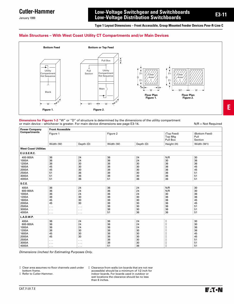
Main Structures – With West Coast Utility CT Compartments and/or Main Devices
Dimensions (inches) for Estimating Purposes Only.
Dimensions for Figures 1-2 “W” or “D” of structure is determined by the dimensions of the utility compartment or main device – whichever is greater. For main device dimensions see page E3-14. N/R = Not Required
Power CompanyCompartments
Front Accessible
Figure 1 Figure 2 (Top Feed)Top MtgPull Box
(Bottom Feed)PullSection
Width (W) Depth (D) Width (W) Depth (D) Height (H) Width (W1)
West Coast Utilities
E.U.S.E.R.C.
400-800A1000A1200A1600A 2000A 2500A3000A4000A
3636384545515151
2424303030363636
3636383838383851
2424303030303036
N/R30363636363636
3036364545515151
S.C.E.
400A 600-800A1000A1200A1600A2000A 2500A3000A4000A
363636384545. . .. . .. . .
242424303030. . .. . .. . .
363636383838383851
242424303030303036
N/RN/R30363636363636
303036364545515151
L.A.D.W.P.
400A 600-800A1000A1200A1600A2000A 2500A3000A4000A
363636384545. . .. . .. . .
242424303030. . .. . .. . .
363636383838383851
242424303030303036
➁➁➁➁➁➁➁➁➁
303036364545515151
➀ Clear area assumes no floor channels used under bottom frame.
➁ Refer to Cutler-Hammer.
Bottom Feed Bottom or Top Feed
Figure 1. Figure 2.
Floor PlanFigure 1.
Floor PlanFigure 2.
➂ Clearance from walls (on boards that are not rear accessible) should be a minimum of 1/2 inch for indoor boards. For boards used in outdoor orwet locations the clearance should be no lessthan 6 inches.
CAT.71.01.T.E
Cutler-HammerJanuary 1999
E
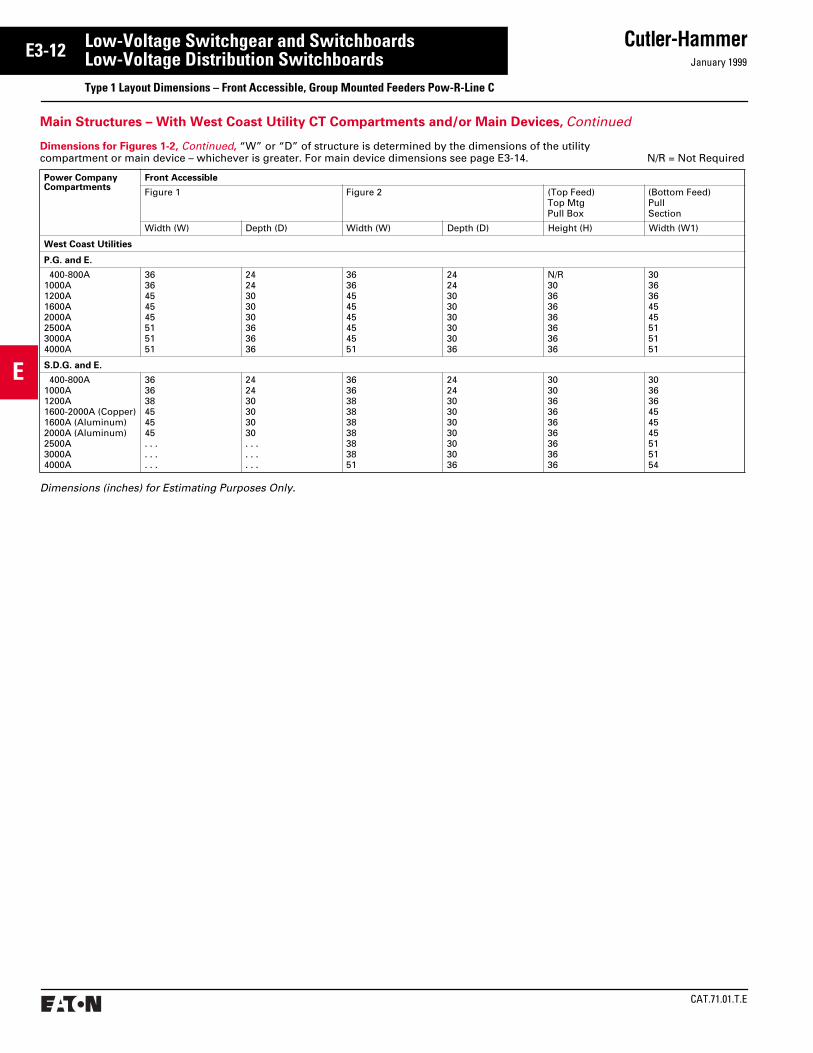
E3-12 Low-Voltage Switchgear and SwitchboardsLow-Voltage Distribution SwitchboardsType 1 Layout Dimensions – Front Accessible, Group Mounted Feeders Pow-R-Line C
Main Structures – With West Coast Utility CT Compartments and/or Main Devices, Continued
Dimensions (inches) for Estimating Purposes Only.
Dimensions for Figures 1-2, Continued, “W” or “D” of structure is determined by the dimensions of the utility compartment or main device – whichever is greater. For main device dimensions see page E3-14. N/R = Not Required
Power CompanyCompartments
Front Accessible
Figure 1 Figure 2 (Top Feed)Top MtgPull Box
(Bottom Feed)PullSection
Width (W) Depth (D) Width (W) Depth (D) Height (H) Width (W1)
West Coast Utilities
P.G. and E.
400-800A1000A1200A1600A2000A2500A3000A4000A
3636454545515151
2424303030363636
3636454545454551
2424303030303036
N/R30363636363636
3036364545515151
S.D.G. and E.
400-800A1000A1200A1600-2000A (Copper)1600A (Aluminum)2000A (Aluminum)2500A3000A4000A
363638454545. . .. . .. . .
242430303030. . .. . .. . .
363638383838383851
242430303030303036
303036363636363636
303636454545515154

January 1999
Cutler-Hammer
CAT.71.01.T.E
E
E3-13Low-Voltage Switchgear and SwitchboardsLow-Voltage Distribution SwitchboardsType 1 Layout Dimensions – Front Accessible, Group Mounted Feeders Pow-R-Line C
Dimensions (inches) for Estimating Purposes Only.
Main Device Dimensions for Figures 1-4
MainDevice
Max.AmpRating
Width(W)
Depth(D)
PullSection(W1)
Fixed Mounted Devices
Molded Case Breakers
Available With Optional Integral GFP
KD, HKD, KDCLD, HLD, LDCMDL, HMDLND, HND, NDCRD, RDCRD, RDC RD, RDC
400 600 8001200160020002500
36363636363636
30303030303030
20202026262626
100% Rated Molded Case Breakers
Available With Optional Integral GFP
CKD, CHKDCLD, HCLD, CLDCCMDL, CHMDLCND, CHND, CNDCCRD, CRDCCRD, CRDC
400 600
8001200
16002000
3636
3636
3636
3030
3030
3030
2020
2020
2626
TRI-PAC Fuse Type Current Limiting Breakers
LA-PNB-PPB-P
400 8001600
363636
303030
202026
Main Structure – With Standard (NEMA) Utility CT Compartments and/or Main Device
Bottom Entrance Top Entrance Bottom Entrance Top Entrance
MainDevice
Max.AmpRating
Width(W)
Depth(D)
PullSection(W1)
Fixed Mounted Devices
100% Rated Power Circuit Breakers
Available With Optional Integral GFP
Magnum DS and DSMagnum DS and DSMagnum DS and DSMagnum DS and DSMagnum DS and DS
800
1600
2000
3200
4000
36
36
36
45
45
36
36
36
48
48
26
26
26
30
30
FDPW Fusible Switches
FDPW400FDPW600FDPW800FDPW1200
400 600 8001200
36363636
30303030
20202026
100% Rated Electric Trip Bolted Pressure Switches
Available With Optional GFP
CBC-800CBC-1200CBC-1600CBC-2000CBC-2500CBC-3000CBC-4000CBC-5000➂
CBC-6000➂
80012001600200025003000400050006000
36363636454545
30303030363636
20262626303030
Refer to Cutler-HammerRefer to Cutler-Hammer
100% Rated Manual Bolted Pressure Switches
Not Available With Ground Fault Protection
QA-800QA-1200QA-1600QA-2000QA-2500QA-3000QA-4000QA-5000➂QA-6000➂
80012001600200025003000400050006000
36363636454545
30303030363636
20262626303030
Refer to Cutler-HammerRefer to Cutler-Hammer
MainDevice
Max.AmpRating
Width(W)
Depth(D)
PullSection(W1)
Draw-out Mounted Devices
100% Rated Power Circuit Breakers
Available With Optional Integral GFP
Magnum DS and DSMagnum DS and DSMagnum DS and DSMagnum DS and DSMagnum DS and DSMagnum DS and DSMagnum DS and DSMagnum DS and DSMagnum DS and DSMagnum DS and DSMagnum DS and DS
800
1600
2000
3200
4000
36
36
36
36
36
45
45
45
45
45
45
48
54
48
54
48
48
66
66
54
66
66
26
26
26
26
26
30
N/A
30
30
N/A
30
W1
ClearArea
➁
33
21⁄2
21⁄2
D
W
ClearArea
33
21⁄2
21⁄2
D
Optional GFP
UtilityCompartmentHot Sequence
Main
WD
●
Optional GFP
Main
WD
OptionalCustomerMetering
UtilityCompartment
ColdSequence
➃
Optional GFP
PullSection
UtilityCompartmentHot Sequence
Main
WD
●
W1
➀
90
Optional GFP
Main
WD
W1
OptionalCustomerMetering
90
UtilityCompartment
ColdSequence
PullSection
➀ ➃
Floor Plan,Pull Section
Refer to pages E3-7 to E3-12 for dimensions on special utility CT compartments.
Hot Sequence Utility Cold Sequence Utility
Top Plan,Main Section
Figure 1. Figure 2. Figure 3. Figure 4.
See pages E3-15 to E3-17 for layout of distribution sections.
See pages E3-21 and E3-22 for outdoor rainproof enclosures.
Top mounted pull boxes are available with heights of 12, 18, 24, and 30 inches.
➀ Rigid bus extension into Pull Section is required above 2000A.
➁ Clear area assumes no floor channels used under bottom frame.
➂ Not UL listed.➃ IQ meter mounted to disconnect door as an
alternate location. (When K, L, M, N and R fixed mounted frames and fixed mounted power circuit breakers are used.)
➄ Clearance from walls (on boards that are not rear accessible) should be a minimum of 1/2 inch for indoor boards. For boards used in outdoor orwet locations the clearance should be no lessthan 6 inches.

CAT.71.01.T.E
Cutler-HammerJanuary 1999
E
E3-14 Low-Voltage Switchgear and SwitchboardsLow-Voltage Distribution SwitchboardsType 1 Layout Dimensions – Front Accessible, Group Mounted Feeders Pow-R-Line C
33
12 Clear Area
W
ClearArea
➁
33
21⁄2
21⁄2
D
Optional GFP
Main
WD
OptionalCustomerMetering➂
➅4000AMax.
24”(Min.)
Optional GFP
2500AMax.
36”(Min.)
22XDist.
Classis
Main
●●
Top Pull Box
24”(Min.)
Optional GFP
2500AMax.
36”(Min.)
PullSection
22XDist.
Classis
Main
●●
Optional GFP
Main➅
WD
●
OptionalCustomerMetering➀
90
Optional GFP
Main
WD
●
OptionalCustomerMetering➀
Dimensions (inches) for Estimating PurposesOnly.
Main DeviceDimensions for Figures 1, 2 and 5 – shown belowDimensions for Figures 3 and 4 – use larger allowable dimension of main (shown below) or distribution mounted devices (see pages E3-15-E3-17).
MainDevice
Max.AmpRating
Width (W) Depth(D)Zero
SequenceGFP
No GFP or WithIntegral GFP
Fixed Mounted Devices
Molded Case Breakers
Available With Optional Integral GFP
KD, HKD, KDCLD, HLD, LDCMDL, HMDLND, HND, NDCRD, RDCRD, RDC RD, RDC
400 600 8001200160020002500
30303030303030
30303030303030
24242424303030
100% Rated Molded Case Breakers
Available With Optional Integral GFP
CKD, CHKDCLD, HCLD, CLDCCMDL, CHMLCND, CHND, CNDCCRD, CRDCCRD, CRDC
400 600
8001200
16002000
3030
3030
3030
2626
2626
2626
1818
1818
3030
TRI-PAC Fuse Type Current Limiting Breakers➀
LA-PNB-PPB-P
400 8001600
303030
262626
181824
Top Entrance Top Mounted Main With Distribution Chassis
➀ These devices cannot be bottom (Fig. 1) fed and will require pull section. Obtain width (W1) from table on page E3-13 for device in question.
➁ Clear area assumes no floor channels used under bottom frame.
➂ Customer metering with IQ meter requires 30-inch minimum width.
➃ Not UL listed.➄ Bottom feed switch structure depth per Fig. 1
is 36-inch minimum.➅ IQ meter mounted to disconnect door as an
alternate location. (When K, L, M, N and R fixed mounted frames and fixed mounted power circuitbreakers are used.)
➆ Clearance from walls (on boards that are not rear accessible) should be a minimum of 1/2 inch for indoor boards. For boards used in outdoor orwet locations the clearance should be no lessthan 6 inches.
Main Structure – With Customer Metering and/or Main Device
Bottom Entrance Mid Mounted Main
Load Cross Bus
MainDevice
Max.AmpRat-ing
Width (W) Depth(D)Zero
SequenceGFP
No GFPor WithIntegralGFP
Fixed Mounted Devices
100% Rated Power Circuit Breakers
Available With Optional Integral GFP
Magnum DS and DSMagnum DS and DSMagnum DS and DSMagnum DS and DS
800
1600
2000
3200
4000
36
36
36
36
45
36
36
36
36
45
36
36
36
48
48FDPW Fusible Switches
FDPW400FDPW600FDPW800FDPW1200
400 600 8001200
30303030
26263030
18181818
100% Rated Electric Trip Bolted Pressure Switches
Available With Optional GFP➄
CBC-800CBC-1200CBC-1600CBC-2000CBC-2500CBC-3000CBC-4000CBC-5000➃
CBC-6000➃
80012001600200025003000400050006000
36363636454545
36363636454545
30303030363636
Refer to Cutler-HammerRefer to Cutler-Hammer
100% Rated Manual Bolted Pressure Switches
Not Available With Ground Fault Protection➄
QA-800QA-1200QA-1600QA-2000QA-2500QA-3000QA-4000QA-5000➃QA-6000➃
80012001600200025003000400050006000
N/AN/AN/AN/AN/AN/AN/A
30303030364545
30303030303636
Refer to Cutler-HammerRefer to Cutler-Hammer
Top Entrance Bottom Mounted Main Load
Cross Bus
Bottom Entrance Top Mounted Main With Distribution Chassis
Top or Bottom Entry Mid Mounted Main
Cable Exit
Floor or Top Plan
Pull Section Minimum Dimensions400-800A : 20 inches W
1200-2000A : 26 inches W2500A : 30 inches W
Height and Depth same as Main Structure
Top Pull Box Minimum Dimensions400-800A : 12 inches H
1200-2000A : 18 inches H2500A : 24 inches H
Width and Depth same as Main Structure
Floor Plan
Figure 1. Figure 2. Figure 3. Figure 4. Figure 5.(Fixed Mounted Devices Only)
Dist. Sect.Figs. 3 & 4
MainDevice
Max.AmpRating
Width (W) Depth(D)Zero
SequenceGFP
No GFPor WithIntegralGFP
Draw-out Mounted Devices
100% Rated Power Circuit Breakers
Available With Optional Integral GFP
Magnum DS and DSMagnum DS and DSMagnum DS and DSMagnum DS and DSMagnum DS and DSMagnum DS and DSMagnum DS and DSMagnum DS and DSMagnum DS and DSMagnum DS and DSMagnum DS and DS
800
1600
2000
3200
4000
36
36
36
36
36
45
45
45
45
45
45
36
36
36
36
36
45
45
45
45
45
45
48
54
48
54
48
48
66
66
54
66
66
See pages E3-15 to E3-17 for layout of distribution sections.
See pages E3-21 and E3-22 for outdoor rainproof enclosures.
Top mounted pull boxes are available with heights of 12, 18, 24, and 30 inches.

January 1999
Cutler-Hammer
CAT.71.01.T.E
E
E3-15Low-Voltage Switchgear and SwitchboardsLow-Voltage Distribution SwitchboardsType 1 Layout Dimensions – Front Accessible, Group Mounted Feeders Pow-R-Line C
90
2436, 45
22XDeviceSpace
OptionalCustomerMetering
orBlank
90
18➃36, 45
38XVerticalPanelSpace
forDevices
BuswayConnection
90
18➃36, 45
50XVerticalPanelSpace
forDevices
66
21⁄2D ClearArea
➂
21⁄2
W(Front)
➀ For compression lugs use #250-750 kcmil lugdimensions.
➁ Dimensions shown are for top entry on 38X Chassis only. For bottom entry use 50X Chassis space requirements.
➂ Clear area assumes no floor channels used under bottom frame.
➃ For panels rated above 2000 amperes, minimum depth is 24 inches.
➄ Clearance from walls (on boards that are not rear accessible) should be a minimum of 1/2 inch for indoor boards. For boards used in outdoor orwet locations the clearance should be no lessthan 6 inches.
Distribution Sections – Group Mounted Devices
See Layout Guides for proper structure width.
See layout guides on pages E3-16 and E3-17 for feeder “x” sizes.
Max. 2000 amperesCT Compartment
Combination Section
BuswayConnection
Full Distribution Section
Floor Plan
Table 1: Main Lug Only Space Requirements
Lug➀Range (kcmil)
”X“ Space Required
50X Chassis
38XChassis➁
400 & 600A
2-#2-500 10 10
2-#250-750 16 10
800A 3-#2-500 10 10
3-#250-750 16 10
1200A 4-#2-500 12 12
4-#250-750 16 12
1600A 5-#2-500 12 12
5-#250-750 16 12
2000A 6-#2-500 12 12
6-#250-750 16 12
For 400-4000 amperes: Incoming cable or busway enters top or bottom of pull section,terminating in cross bus extension. For pull section dimensions refer to pages E3-13 and E3-14.
Dimensions (inches) for Estimating Purposes Only.
Main Lug Distribution SizingMain lugs may be accomplished in two ways.
1. Main lugs on distribution panel using space requirements in Table 1.
2. With a bussed auxiliary structure for incoming cable per Fig. 1.
Figure 1.
WallCross Bus
PNL’BD PNL’BD
● ●
IncomingConduits
W W
18
PullSection
Top Section View

CAT.71.01.T.E
Cutler-HammerJanuary 1999
E
E3-16 Low-Voltage Switchgear and SwitchboardsLow-Voltage Distribution SwitchboardsType 1 Layout Dimensions – Front Accessible, Group Mounted Feeders Pow-R-Line C
➀ 100% rated breakers.
1X
2X
▲
1P 1P
2P 2P
3P 3P
2P 2P
3P 3P
2 or 3P
Filler
TVSSClipper
2 or 3P
2 or 3P
Load
2 or 3P 2 or 3P
2 or 3P 2 or 3P
2 or 3P
2 or 3P
2 or 3P 2 or 3P
2 or 3P
▲ ▲
▲
▲
▲ ▲
▲
▲
▲
▲ Breaker may be used as main.
45" W
ide
Stu
rctu
re
36" W
ide
Str
uctu
re
1X
11X
3X
2X
3X
3X
4X
6X
3X
3X
6X
6X
4X
6X
IQMetering
Earth3P
Leakage
Earth3P
Leakage
3PEarth Leakage
▲
3PEarth Leakage
▲
10X
3X
3X
4X
FrameMaximumAmperes
600
1200
400
225
150
250
250
400
400
100
250
800
1200
Breaker to FusibleTransition, All Widths
TVSS Clipper
EHD
FDB, FD, HFD, FDC
ED, EDH, EDC,FD, HFD, FDC
JD, JDB, HJD, JDC
DK, KD, KDB, HKD,KDC, CKD➀, CHKD➀
LD, LDB, HLD, LDC,CLD➀, CHLD➀, CLDC➀
FB-P
JD, JDB, HJD, JDC
LA-P
MDL, HMDL,CMDL➀, CHMDL➀
ND, HND,NDC
DK, KD, KDB,HKD, KDC
NB-P
CND➀, CHND➀, CNDC➀
IQ Metering
ELFD, ELHFD, ELFDC
ELJD, ELHJD, ELJDC
ELKD, ELHKD, ELKDC
100
150
400
800
Distribution Layout Guide – Molded Case Breakers
1X = 1-3/8 inches
January 1999
Cutler-Hammer
CAT.71.01.T.E
E
E3-17Low-Voltage Switchgear and SwitchboardsLow-Voltage Distribution SwitchboardsType 1 Layout Dimensions – Front Accessible, Group Mounted Feeders Pow-R-Line C
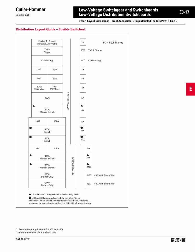
Distribution Layout Guide – Fusible Switches➀
36" W
ide
Str
uctu
re
Fusible To BreakerTransition, All Widths
100A250V Max.
▲
●
●
▲
▲
●
●
▲
▲
100A250V Max.
60A 60A
30A 30A
100A
200AMain or Branch
100A 100A
400ABranch
600ABranch
400AMain or Branch
800ABranch Only
600AMain or Branch
1200ABranch Only
200A 200A
45" W
ide
Str
uctu
re
1X
4X
4X
4X
5X
6X
5X
9X
11X
6X
9X
11X
11X
15X (16X with Shunt Trip)
(16X with Shunt Trip)
▲ Fusible switch may be used as horizontally main.
● 400 and 600 amperes horizontally mounted feeder switches in 36- or 45-inch wide structure. 400 and 600 amperes�horizontally mounted main switches only in 45-inch wide structure.
▲
TVSSClipper
IQ Metering11XIQ Metering
TVSS Clipper10X
1X = 1-3/8 inches
➀ Ground fault applications for 800 and 1200 ampere switches require shunt trip.

CAT.71.01.T.E
Cutler-HammerJanuary 1999
E
E3-18 Low-Voltage Switchgear and SwitchboardsLow-Voltage Distribution SwitchboardsType 1 Layout Dimensions – Front Accessible Switchboards Pow-R-Line C
DW
Optional GFP
12.00 12.00
51.00
3.003.00
36.00
8.5019.50
Rear of Switchboard
➀
ClearArea
➁
ClearArea
➁
Figure 1.
Floor Plan
Individually Mounted Feeder Devices
Dimensions (inches) for Estimating Purposes Only.
Dimensions for Figure 1Structure width to be determined by device requiring widest structure.
FeederDevice
Max.AmpRating
ZeroSequenceGFP
No GFP or With IntegralGFP
Min.Width(W)
Min.Depth(D)
Min.Width(W)
Min.Depth(D)
Fixed Mounted Devices
100% Rated Electric Trip Bolted Pressure Switches
CBC-800CBC-1200CBC-1600
80012001600
515151
363636
515151
363636
100% Rated Manual Bolted Pressure Switches
Not Available With Ground Fault Protection
QA-800QA-1200QA-1600
80012001600
. . .
. . .
. . .
. . .
. . .
. . .
515151
363636
➀ Verify acceptance with code authorities.➁ Clear area assumes no floor channels used under
front or rear frame members.➂ Clearance from walls (on boards that are not rear
accessible) should be a minimum of 1/2 inch for indoor boards. For boards used in outdoor orwet locations the clearance should be no lessthan 6 inches.
Top mounted pull boxes are available with heights of 12, 18, 24, and 30 inches.

January 1999
Cutler-Hammer
CAT.71.01.T.E
E
E3-19Low-Voltage Switchgear and SwitchboardsLow-Voltage Distribution Switchboards
30" HighCover
BIM➁➂12
33
90
Door
Main
Figure 1.Any Main
Top Entry or with UGPS
30DMin.
UGPS
3" High Cover
Figure 2.K, L, M, N, R, and APCB
Main Breaker
3" High Cover12" High
Door
BIM➁➂
30
W
15
90 Main
30" HighBlank or ColdSequenceNEMA CT Compt. 30D
Min.
Figure 3.Bolted Pressure
Main Switch
9" High Cover
DoorBIM➁➂
30
12
9
3990 Bolted PressureSwitch
30" HighBlank or ColdSequenceNEMA CT Compt. 30D
Min.
Figure 4.Main
Hot Sequence NEMA Utility
3" High Cover
6" High Cover
Door BarrierBIM➁➂
39
12
3
6
3090
Hot SequenceNEMA Utility
Main
30DMin.
W
Type 1 Layout Dimensions – Front Accessible OPTIM Trip Units in Switchboards Group Mounted Feeder Devices
Cross Bus
PNL'BD PNL'BD
Pull SectionTop View
IncomingConduits
W W
Wall
24
Figure 2. Dimensions
Device Frame “W” Min. Width Sect.
K 30
L 30
M 36
N 36
R 36
APCB 800-2000A 36
APCB 2500-3000A 45
APCB 4000A 51
FixedMtd.Only
Figure 7.
For 400-4000 amperes: Incoming cable or busway enters top or bottom of pull section, terminating in cross bus section.
Front Accessible Main Sections➀
➀ 50X distribution chassis can be used when main section accommodates location of breaker inter-face module, or BIM, is mounted above 40X chassis in another structure. Refer to auxiliary distribution for alternate BIM location below.
➁ Power Supply is provided for OPTIM trip units; maximum 25 breakers per power supply.
➂ When a utility compartment other than a NEMA compartment with an individually mounted main is required, see Figure 5 for mounting location of the BIM and associated components.
➃ BIM PROVISION on all 40X distribution sections; (1) BIM supports up to 50 devices. BIM may be located in main section to utilize 50X chassis.
Floor Plan
50X Sectionused onlywhen BIMis locatedin mainsection orwhen BIMis notrequired
➀50X
VerticalPanelSpace
ForDevices
45W24D Min.
BreakerInterfaceModule
40XVerticalPanelSpace
ForDevices
➃
Power Supply
45W
90
HingedWiringGuttersLH/RH Sides(Optional)
HingedWiringGuttersLH/RH Sides(Optional)
24D Min.
See Section B4.
Front Accessible Feeder Sections
➄ Clear area assumes no floor channels used under bottom frame.
➅ Clearance from walls (on boards that are not rear accessible) should be a minimum of 1/2 inch for indoor boards. For boards used in outdoor orwet locations the clearance should be no lessthan 6 inches.
2.25
D
3 3
45.00
12Clear Area➄
Figure 6.Figure 5.
APCB = Air Power Circuit BreakerType Magnum DS or DS

CAT.71.01.T.E
Cutler-HammerJanuary 1999
E
E3-20 Low-Voltage Switchgear and SwitchboardsLow-Voltage Distribution SwitchboardsType 1 Layout Dimensions – Front Accessible OPTIM Trip Units in Switchboards Group Mounted Feeder Devices
1P 1P
FD, HFD, FDCED, EDH, EDC
JD, HJD, JDC
LD, HLD, LDC, CLD➀,CHLD➀, CLDC➀
JD, HJD, JDC
FB-P
LA-P
OPTIM Trip Unit➂See section G3.
2P 2P
1X
➁
➁
➁
➁
2X
3X
2X
4X
8X
3X
3X
6X
8X
4X
3P 3P
2P 2P
3P
2 or 3P
2 or 3P
2 or 3P
2 or 3P 2 or 3P
2 or 3P
2 or 3P
2 or 3P
2 or 3P 2 or 3P
45"
Wid
e S
tru
ctu
re F
ron
t A
cces
s
2 or 3P
Load
3P
40X/50XAvailable
DistributionSpace
6X
OPTI
M
6X
OPTI
M
KD, HKD, KDC,CKD, CHKD
OPTIM Trip Unit➂See section G3.
MaximumAmperes Frame
225➀
250➀
600
250➀
100➀
400➀
400
EHD
FD, HFD, FDC
100➀
150➀
Earth3P
Leakage
Earth3P
Leakage
3PEarth Leakage
3PEarth Leakage
3X
3X
3X
4X
ND, HND,NDC
OPTIM Trip Unit➂See section G3.
1200
KD, HKD, KDC400➀
ELFD, ELHFD, ELFDC150➀
ELJD, ELHJD, ELJDC250
ELKD, ELHKD, ELKDC400➀
3X
MDL, HMDL,CMDL, CHMDL
6X2 or 3P 800➁
OPTI
M
Distribution Layout Guide – Molded Case Breakers
Refer to page E3-19 for additional breaker interface module locations when a utility compartment is not required.
Main Lugs may be accomplished only by add-ing a bussed pull section.
Optimizer and instruction manual supplied with each switchboard line up.
Hand-Held Optimizer (programming unit) See section G3.
Seismic Qualified.
➀ Non-OPTIM, Available with Energy Sentinel. ➁ All breakers with residual ground fault (including
provisions) require neutral sensors.➂ Power Supply is provided for OPTIM trip units;
maximum 25 breakers per power supply.

January 1999
Cutler-Hammer
CAT.71.01.T.E
E
E3-21Low-Voltage Switchgear and SwitchboardsLow-Voltage Distribution SwitchboardsType 1 Layout Dimensions – Front Accessible, Group Mounted Feeders – Outdoor Enclosures Pow-R-Line C
Dimension ‘A’
0-2500 kVA Transformer 55.00
2501-5000 kVA Transformer 61.00
Front Access – Non-Walk-in With Flat Roof
➀ 20-inch wide structure always required when throat connecting to other equipment. Standard transformer throat connection, 48-inch deep only.
➁ Standard busway entry/exit location, 36-inch deep minimum.
➂ Clearance from walls (on boards that are not rear accessible) should be a minimum of 1/2 inch for indoor boards. For boards used in outdoor orwet locations the clearance should be no lessthan 6 inches.
Dimensions (inches) for Estimating Purposes Only.
Switchboard IndoorStructure Depth
Non-Walk-in Enclosure Depth
24 (not available for XFMR)30 (not available for XFMR)36 (not available for XFMR)48 (minimum for XFMR connection)
37434961
Enclosure Depth
Swbd. Struc.Depth
Front ofPRL C InnerStructure
44.00
22.00
20.00
2.125
4.50 1.25
StructureWidth
‘A’To
Floor
Transition ➀
5.00
90.70
2.15
➁
12.81Structure Width20.00
17.37
➁
➀➀
CAT.71.01.T.E
Cutler-HammerJanuary 1999
E
E3-22 Low-Voltage Switchgear and SwitchboardsLow-Voltage Distribution SwitchboardsType 1 Layout Dimensions – Front Accessible, Group Mounted Feeder Devices Pow-R-Line C
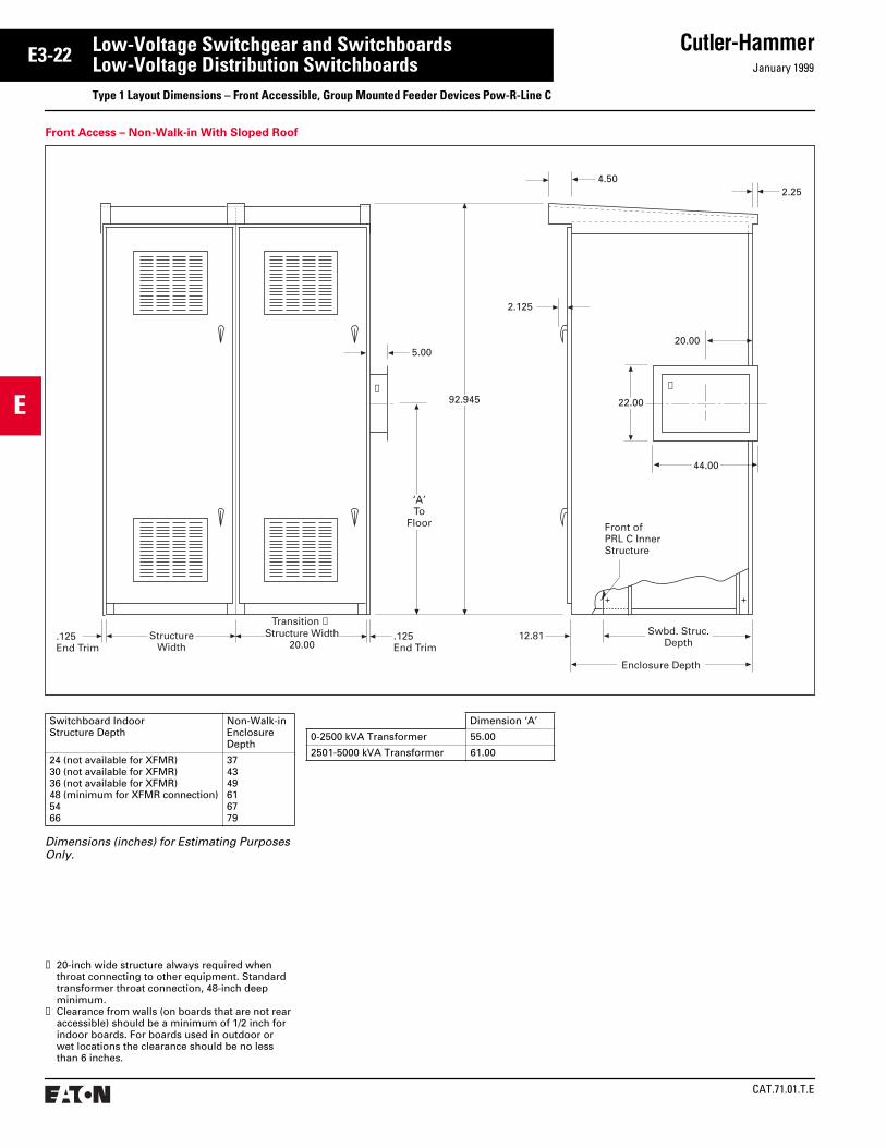
Front Access – Non-Walk-in With Sloped Roof
Dimensions (inches) for Estimating Purposes Only.
Switchboard IndoorStructure Depth
Non-Walk-in Enclosure Depth
24 (not available for XFMR)30 (not available for XFMR)36 (not available for XFMR)48 (minimum for XFMR connection)54 66
374349616779
➀ 20-inch wide structure always required when throat connecting to other equipment. Standard transformer throat connection, 48-inch deep minimum.
➁ Clearance from walls (on boards that are not rear accessible) should be a minimum of 1/2 inch for indoor boards. For boards used in outdoor orwet locations the clearance should be no lessthan 6 inches.
.125End Trim
Enclosure Depth
Swbd. Struc.Depth
Front ofPRL C InnerStructure
44.00
22.00
20.00
2.125
4.502.25
StructureWidth
‘A’To
Floor
5.00
92.945
.125End Trim
12.81Transition ➀
Structure Width20.00
➀➀
Dimension ‘A’
0-2500 kVA Transformer 55.00
2501-5000 kVA Transformer 61.00

January 1999
Cutler-Hammer
CAT.71.01.T.E
E
E3-23Low-Voltage Switchgear and SwitchboardsLow-Voltage Distribution SwitchboardsType 2 Layout Information – Rear Accessible, Group Mounted Feeder Devices
Type 2Pow-R-Line C Switchboards
Meets NEMA Standard PB-2 and UL 891.
Construction Details● 6000 Ampere Main Bus Maximum.● Front and rear accessible – Main sections
front and/or side accessible.● Feeder devices panel mounted.● Sections rear aligned or front and rear
aligned.● Not designed for mounting against a wall,
self-supporting and requires code clear-ance at the rear.
Main Devices, Individually Mounted● Molded Case Circuit Breaker, 400-2500
Amperes, fixed or draw-out.● Air Power Circuit Breaker; DS and
Magnum DS, 800-5000 Amperes, fixed or draw-out.
● Air Power Circuit Breaker with Current Limiting Fuses, DSL, 800-5000 Amperes.
● Bolted Pressure Switch, 800-6000 Amperes, fixed.
● Fusible Switches; FDPW, 400-1200 Amperes, fixed.
Feeder Devices, Group Mounted● Molded Case Circuit Breakers, 15-1200
Amperes.● Fusible Switches; FDPW, 30-1200
Amperes.
Feeder Devices, Individually Mounted● Air Power Circuit Breakers, DS 800-2500
Amperes. ● Bolted Pressure Switches,
800-2500 Amperes, fixed.
CAT.71.01.T.E
Cutler-HammerJanuary 1999
E
E3-24 Low-Voltage Switchgear and SwitchboardsLow-Voltage Distribution SwitchboardsType 2 Layout Information – Rear Accessible, Group Mounted Feeder Devices
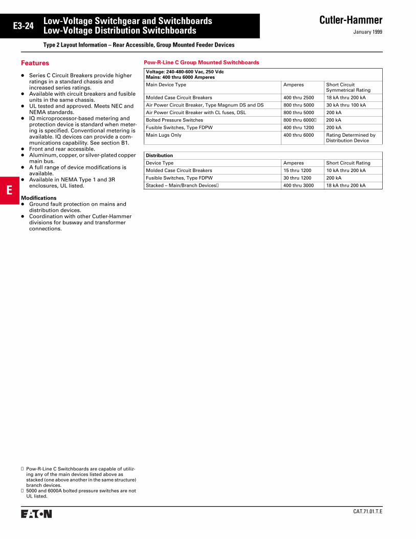
Features
● Series C Circuit Breakers provide higher ratings in a standard chassis and increased series ratings.
● Available with circuit breakers and fusible units in the same chassis.
● UL tested and approved. Meets NEC and NEMA standards.
● IQ microprocessor-based metering and protection device is standard when meter-ing is specified. Conventional metering is available. IQ devices can provide a com-munications capability. See section B1.
● Front and rear accessible.● Aluminum, copper, or silver-plated copper
main bus.● A full range of device modifications is
available.● Available in NEMA Type 1 and 3R
enclosures, UL listed.
Modifications● Ground fault protection on mains and
distribution devices.● Coordination with other Cutler-Hammer
divisions for busway and transformer connections.
Pow-R-Line C Group Mounted Switchboards
Voltage: 240-480-600 Vac, 250 VdcMains: 400 thru 6000 Amperes
Main Device Type Amperes Short Circuit Symmetrical Rating
Molded Case Circuit Breakers 400 thru 2500 18 kA thru 200 kA
Air Power Circuit Breaker, Type Magnum DS and DS 800 thru 5000 30 kA thru 100 kA
Air Power Circuit Breaker with CL fuses, DSL 800 thru 5000 200 kA
Bolted Pressure Switches 800 thru 6000➁ 200 kA
Fusible Switches, Type FDPW 400 thru 1200 200 kA
Main Lugs Only 400 thru 6000 Rating Determined by Distribution Device
Distribution
Device Type Amperes Short Circuit Rating
Molded Case Circuit Breakers 15 thru 1200 10 kA thru 200 kA
Fusible Switches, Type FDPW 30 thru 1200 200 kA
Stacked – Main/Branch Devices➀ 400 thru 3000 18 kA thru 200 kA
➀ Pow-R-Line C Switchboards are capable of utiliz-ing any of the main devices listed above as stacked (one above another in the same structure) branch devices.
➁ 5000 and 6000A bolted pressure switches are not UL listed.

January 1999
Cutler-Hammer
CAT.71.01.T.E
E
E3-25Low-Voltage Switchgear and SwitchboardsLow-Voltage Distribution SwitchboardsType 2 Layout Dimensions – Rear Accessible, Group Mounted Feeders Pow-R-Line C
Main Structures – With Special Utility CT Compartments and/or Main Devices
Dimensions for Estimating Purposes Only.
Dimensions for Figures 1-4 “W” or “D” of structure is determined by the dimensions of the utility compartment or main device – whichever is greater. For main device dimensions see page E3-32. N/A = Not Applicable
Power CompanyCompartments
MeteringSequence
Rear Accessible
Figure 1 Figure 2 Figure 3 Figure 4
W D D D CC D CC
Atlantic City Electric Hot
800A1200A1600-2000A2500-4000A
36364545
36484848
36484848
36484848
6 61212
N/AN/AN/AN/A
. . . .
. . . .
. . . .
. . . .
Baltimore Gas and Electric➅ Hot
800A1200-2500A3000-4000A
36/45➅36/45➅45➅
36/30➅36/30➅30➅
36/30➅36/30➅30➅
➀➀➀
➀➀➀
N/AN/AN/A
. . . .
. . . .
. . . .
Boston Edison Cold
800-1600A2000-2500A3000-4000A
363636➃
N/AN/AN/A
N/AN/AN/A
N/AN/AN/A
. . . .
. . . .
. . . .
303636➃
61212➃
Central Hudson Gas and Electric Hot➇/Cold ➄ ➄ ➄ ➄ ➄ N/A . . . .
Central Vermont Hot ➄ ➄ ➄ ➄ ➄ N/A N/A
Cincinnati Gas and Electric Hot
800A1000A1200-2000A2500-4000A
36364545
30303636
30303636
36364848
6 61212
N/AN/AN/AN/A
. . . .
. . . .
. . . .
. . . .
Commonwealth Edison Hot
400-1000A1200-2000A2500-4000A
363636
364848
364848
364848
6 612
N/AN/AN/A
. . . .
. . . .
. . . .
Bottom Feed Top Feed Bottom or Top Feed Bottom or Top Feed
Figure 1. Figure 2. Figure 3. Figure 4. (Cold Sequence)
W
ClearArea
➆
33
21⁄2
21⁄2
D
Blank
UtilityCompartmentHot Sequence
WD
●
●
Blank
UtilityCompartmentHot Sequence
WD
Main
WD
UtilityCompartmentHot Sequence
Main2500AmpMax.➃
WD
UtilityCompartment
ColdSequence
W33
CCClear Area➆
Floor PlanFigures 3. and 4.
Floor PlanFigure 1.
➀ Refer to Cutler-Hammer.➁ For limiter lugs or more than six (6) mechanical
lugs per phase, a separate pull section is required.➂ For limiter lugs or more than six (6) mechanical
lugs per phase, a 12-inch pull box is required.➃ Cold sequence: 3000A or 4000A main device must
be mounted in separate structure. Refer to page E3-32, Figs. 1 and 2. The utility compartment will then be housed in the second structure. Branch devices or customer metering can then be mounted in remaining half of utility compartment structure.
➄ Dimensions are the same as standard NEMA utility compartments, refer to page E3-31.
➅ For BG&E, the utility compartment is mounted in the bottom for Fig. 1 and top for Fig. 2. For bottom feed (Fig. 1); up to 2500 amperes, the main is mounted in top. For 3000A and 4000A bottom feed, the main is in a separate structure. For top feed (Fig. 2), maximum amperes is 4000A and the main is mounted in the bottom.
➆ Clear area assumes no floor channels used under bottom frame.
➇ For special applications approved by the utility.➈ Clearance from walls (on boards that are not rear
accessible) should be a minimum of 1/2 inch for indoor boards. For boards used in outdoor orwet locations the clearance should be no lessthan 6 inches.

CAT.71.01.T.E
Cutler-HammerJanuary 1999
E
E3-26 Low-Voltage Switchgear and SwitchboardsLow-Voltage Distribution SwitchboardsType 2 Layout Dimensions – Rear Accessible, Group Mounted Feeders
Dimensions (inches) for Estimating Purposes Only.
Dimensions for Figures 1-4, Continued, “W” or “D” of structure is determined by the dimensions of the utility compartment or main device – whichever is greater. For main device dimensions see page E3-32. N/A = Not Applicable
Power CompanyCompartments
MeteringSequence
Rear Accessible
Figure 1 Figure 2 Figure 3 Figure 4
W D D D CC D CC
Connecticut Light and Power Hot➇/Cold
800-1200A1600-2000A2500-4000A
➄3636/45
➄3036
➄3036
➄4848
➄N/AN/A
➄4848➃
➄1212➃
Consolidated Edison Hot
800A (Spec. 298)1200A-1600A (Spec. 298) 1200-2000A (Spec. 377)2500-4000A (Spec. 377)
38384545
30303636
30➀30➀36➀36➀
36364848
6 61212
N/AN/AN/AN/A
. . . .
. . . .
. . . .
. . . .
Detroit Edison Hot
800A1200-2000A2500-4000A
363645
363648
363648
363648
6 612
N/AN/AN/A
. . . .
. . . .
. . . .
Florida Power and Light Hot ➄ ➄ ➄ ➄ ➄ N/A . . . .
Georgia Power Co. Hot ➄ ➄ ➄ ➄ ➄ N/A . . . .
Indianapolis Power Co. Hot/Cold➇
800A1200-2000A2500-4000A
363636
363636
363636
484848
121212
484848➃
121212➃
Jersey Central Power Hot➇/Cold
800A1200-2000A2500-4000A
➄4545
➄4848
➄4848
➄4848
➄1212
➄4848➃
➄1212➃
Kansas City Power and Light Hot ➄ ➄ ➄ ➄ ➄ N/A . . . .
Long Island Light Co. Hot
800-1200A1600-2000A2500-4000A
384545
243636
243636
364848
61212
N/AN/AN/A
. . . .
. . . .
. . . .
Louisville Gas and Electric Hot
800A1200-2000A2500-3000A
364545
484848
484848
484848
61212
N/AN/AN/A
. . . .
. . . .
. . . .
Madison Gas and Electric Cold
800-1200A1600-2000A2500-3000A
363645
N/AN/AN/A
N/AN/AN/A
N/AN/AN/A
. . . .
. . . .
. . . .
363648➃
6 612➃
Massachusetts Electric Hot
800A1200-2000A2500-4000A
➄3636/45
➄3036
➄3036
➄3048
➄ 612
N/AN/AN/A
. . . .
. . . .
. . . .
Metropolitan Edison Hot ➄ ➄ ➄ ➄ ➄ N/A . . . .
Monongahela Power Hot 45 48 48 48 ➄ N/A . . . .
Naperville Hot ➄ ➄ ➄ ➄ ➄ N/A . . . .
Narragansett Hot
800A1200-2000A2500-4000A
➄3636/45
➄3036
➄3036
➄3648
➄ 612
N/AN/AN/A
. . . .
. . . .
. . . .
Main Structures – With Special Utility CT Compartments and/or Main Devices, Continued
➀ Refer to Cutler-Hammer.➁ For limiter lugs or more than six (6) mechanical
lugs per phase, a separate pull section is required.➂ For limiter lugs or more than six (6) mechanical
lugs per phase, a 12-inch pull box is required.➃ Cold sequence: 3000A or 4000A main device must
be mounted in separate structure. Refer to page E3-32, Figs. 1 and 2. The utility compartment will
then be housed in the second structure. Branch devices or customer metering can then be mounted in remaining half of utility compartment structure.
➄ Dimensions are the same as standard NEMA utility compartments, refer to page E3-31.
➅ For BG&E, the utility compartment is mounted in the bottom for Fig. 1 and top for Fig. 2. For bottom feed (Fig. 1); up to 2500 amperes, the main is
mounted in top. For 3000A and 4000A bottom feed, the main is in a separate structure. For top feed (Fig. 2), maximum amperes is 4000A and the main is mounted in the bottom.
➆ Clear area assumes no floor channels used under bottom frame.
➇ For special applications approved by the utility.

January 1999
Cutler-Hammer
CAT.71.01.T.E
E
E3-27Low-Voltage Switchgear and SwitchboardsLow-Voltage Distribution SwitchboardsType 2 Layout Dimensions – Rear Accessible, Group Mounted Feeders Pow-R-Line C
Dimensions (inches) for Estimating Purposes Only.
Dimensions For Figures 1-4, Continued, “W” or “D” of structure is determined by the dimensions of the utility compartment or main device – whichever is greater. For main device dimensions see page E3-32. N/A = Not Applicable
Power CompanyCompartments
MeteringSequence
Rear Accessible
Figure 1 Figure 2 Figure 3 Figure 4
W D D D CC D CC
New York State Electric and Gas Cold
800-1200A1600-2000A2500-4000A
363645
N/AN/AN/A
N/AN/AN/A
N/AN/AN/A
. . . .
. . . .
. . . .
364848➃
6 6 6➃
Niagara Mohawk Cold
800-1200A1600-2000A2500-4000A
➄3636/45
N/AN/AN/A
N/AN/AN/A
N/AN/AN/A
. . . .
. . . .
. . . .
➄3636➃
➄ 6 6➃
Northeast Utilities Hot➇/Cold
800-1200A1600-2000A2500-4000A
➄3636/45
➄3648
➄3648
➄4848
➄1212
➄4848➃
➄1212➃
Northern States Power Hot
800-1200A1600-2000A2500-4000A
363636/45
303030/36
303030/36
363636/48
6 66/12
N/AN/AN/A
. . . .
. . . .
. . . .
Omaha Public Power Hot
1200-2000A2500-4000A
4545
3636
3636
4848
1212
N/AN/A
. . . .
. . . .
Orange and Rockland Hot ➄ ➄ ➄ ➄ ➄ N/A . . . .
Pennsylvania Power and Light Hot
800-4000A➀ 45 48➁ 48➂ 54 6 N/A . . . .
Philadelphia Electric Company Hot ➄ ➄ ➄ ➄ ➄ N/A . . . .
Main Structures – With Special Utility CT Compartments and/or Main Devices, Continued
Bottom Feed Top Feed Bottom or Top Feed Bottom or Top Feed
Figure 1. Figure 2. Figure 3. Figure 4.(Cold Sequence)
W
ClearArea
➆
33
21⁄2
21⁄2
D
Blank
UtilityCompartmentHot Sequence
WD
●
●
Blank
UtilityCompartmentHot Sequence
WD
Main
WD
UtilityCompartmentHot Sequence
Main2500AmpMax.➄
WD
UtilityCompartment
ColdSequence
W6
CCClear Area➆
6
Floor PlanFigure 1.
Floor PlanFigures 3. and 4.
➀ Refer to Cutler-Hammer.➁ For limiter lugs or more than six (6) mechanical
lugs per phase, a separate pull section is required.➂ For limiter lugs or more than six (6) mechanical
lugs per phase, a 12-inch pull box is required.➃ Cold sequence: 3000A or 4000A main device must
be mounted in separate structure. Refer to page E3-32, Figs. 1 and 2. The utility compartment will then be housed in the second structure. Branch devices or customer metering can then be mounted in remaining half of utility compartment structure.
➄ Dimensions are the same as standard NEMA utility compartments, refer to page E3-31.
➅ For BG&E, the utility compartment is mounted in the bottom for Fig. 1 and top for Fig. 2. For bottom feed (Fig. 1); up to 2500 amperes, the main is mounted in top. For 3000A and 4000A bottom feed, the main is in a separate structure. For top feed (Fig. 2), maximum amperes is 4000A and the main is mounted in the bottom.
➆ Clear area assumes no floor channels used under bottom frame.
➇ For special applications approved by the utility.➈ Clearance from walls (on boards that are not rear
accessible) should be a minimum of 1/2 inch for indoor boards. For boards used in outdoor orwet locations the clearance should be no lessthan 6 inches.

CAT.71.01.T.E
Cutler-HammerJanuary 1999
E
E3-28 Low-Voltage Switchgear and SwitchboardsLow-Voltage Distribution SwitchboardsType 2 Layout Dimensions – Rear Accessible, Group Mounted Feeders Pow-R-Line C
➀ Refer to Cutler-Hammer.➁ For limiter lugs or more than six (6) mechanical
lugs per phase, a separate pull section is required.➂ For limiter lugs or more than six (6) mechanical
lugs per phase, a 12-inch pull box is required.➃ Cold sequence: 3000A or 4000A main device must
be mounted in separate structure. Refer to page E3-32, Figs. 1 and 2. The utility compartment will
then be housed in the second structure. Branch devices or customer metering can then be mounted in remaining half of utility compartment structure.
➄ Dimensions are the same as standard NEMA utility compartments, refer to page E3-31.
➅ For BG&E, the utility compartment is mounted in the bottom for Fig. 1 and top for Fig. 2. For bottom feed (Fig. 1); up to 2500 amperes, the main is
mounted in top. For 3000A and 4000A bottom feed, the main is in a separate structure. For top feed (Fig. 2), maximum amperes is 4000A and the main is mounted in the bottom.
➆ Clear area assumes no floor channels used under bottom frame.
➇ For special applications approved by the utility.
Main Structures – With Special Utility CT Compartments and/or Main Devices, Continued
Dimensions (inches) for Estimating Purposes Only.
Dimensions for Figures 1-4, Continued, “W” or “D” of structure is determined by the dimensions of the utility compartment or main device – whichever is greater. For main device dimensions see page E3-32. N/A = Not Applicable
Power CompanyCompartments
MeteringSequence
Rear Accessible
Figure 1 Figure 2 Figure 3 Figure 4
W D D D CC D CC
Potomac Electric Power Company Hot
800-2000A2500-4000A800-3000A
4000A
36363636
3036N/AN/A
N/AN/A3648
N/AN/AN/AN/A
. . . .
. . . .
. . . .
. . . .
N/AN/AN/AN/A
. . . .
. . . .
. . . .
. . . .
Public Service of Colo. Hot
800A1200-2000A2500-4000A
➄3645
➄3036
➄3036
➄3048
➄ 612
N/AN/AN/A
. . . .
. . . .
. . . .
Public Service Electric and Gas Hot
800A1200-2000A2500A3000A-4000A
36454545
30484848
30484848
36484848
6121212
N/AN/AN/AN/A
. . . .
. . . .
. . . .
. . . .
Public Service of New Hampshire Hot/Cold➇ ➄ ➄ ➄ ➄ ➄ N/A . . . .
Toledo Edison Cold ➄ ➄ ➄ ➄ ➄ N/A . . . .
Union Electric Hot
800-4000A ➄ ➄ ➄ ➄ ➄ N/A N/A
Virginia Power Company Hot
800A1200A1600-2000A2500-4000A
36364545
36363648
36363648
36364848
6 61212
N/AN/AN/AN/A
. . . .
. . . .
. . . .
. . . .
Wisconsin Electric Power Co. Hot
800A1200A1600-3000A4000A
36363645
30303636
30303636
36364848
6 61212
N/AN/AN/AN/A
. . . .
. . . .
. . . .
. . . .
Wisconsin Power and Light Hot
800A1200-2000A2500-3000A
363645
363636
363636
484848
121212
N/AN/AN/A
. . . .
. . . .
. . . .
Wisconsin Public Service Hot
1000-4000A 45 30 48 N/A . . . . N/A . . . .

January 1999
Cutler-Hammer
CAT.71.01.T.E
E
E3-29Low-Voltage Switchgear and SwitchboardsLow-Voltage Distribution SwitchboardsType 2 Layout Dimensions – Rear Accessible, Group Mounted Feeders Pow-R-Line C
W
ClearArea
➀
33
21⁄2
21⁄2
D
●
Blank
UtilityCompartmentHot Sequence
WD
PullSection
UtilityCompartmentHot Sequence
Main
WD
●
W1
HPull Box
W1
ClearArea
➀
W
21⁄2
21⁄2
D
Main Structures – With West Coast Utility CT Compartments and/or Main Devices
Dimensions (inches) for Estimating Purposes Only.
Dimensions for Figures 1-2 “W” or “D” of structure is determined by the dimensions of the utility compartment or main device – whichever is greater. For main device dimensions see page E3-32. N/R = Not Required
Power CompanyCompartments
Front or Rear Accessible
Figure 1 Figure 2 (Top Feed)Top MtgPull Box
(Bottom Feed)PullSection
Width (W) Depth (D) Width (W) Depth (D) Height (H) Width (W1)
West Coast Utilities
E.U.S.E.R.C.
400-800A1000A1200A1600A2000A 2500A3000A4000A
3636384545515151
2424303030363636
3636383838383851
2424303030303036
N/R30363636363636
3036364545515151
S.C.E.
400A 600-800A1000A1200A1600A2000A2500A3000A4000A
363636384545. . .. . .. . .
242424303030. . .. . .. . .
363636383838383851
242424303030303036
N/RN/R30363636363636
303036364545515151
L.A.D.W.P.
400A 600-800A1000A1200A1600A2000A 2500A3000A4000A
363636384545. . .. . .. . .
242424303030. . .. . .. . .
363636383838383851
242424303030303036
➁➁➁➁➁➁➁➁➁
303036364545515151
➀ Clear area assumes no floor channels used under bottom frame.
➁ Refer to Cutler-Hammer.
Bottom Feed Bottom or Top Feed
Figure 1. Figure 2.
Floor PlanFigure 1.
Floor PlanFigure 2.
➂ Clearance from walls (on boards that are not rear accessible) should be a minimum of 1/2 inch for indoor boards. For boards used in outdoor orwet locations the clearance should be no lessthan 6 inches.

CAT.71.01.T.E
Cutler-HammerJanuary 1999
E
E3-30 Low-Voltage Switchgear and SwitchboardsLow-Voltage Distribution SwitchboardsType 2 Layout Dimensions – Rear Accessible, Group Mounted Feeders Pow-R-Line C
Main Structures – With West Coast Utility CT Compartments and/or Main Devices, Continued
Dimensions (inches) for Estimating Purposes Only.
Dimensions for Figures 1-2, Continued, “W” or “D” of structure is determined by the dimensions of the utility compartment or main device – whichever is greater. For main device dimensions see page E3-32. N/R = Not Required
Power CompanyCompartments
Front or Rear Accessible
Figure 1 Figure 2 (Top Feed)Top MtgPull Box
(Bottom Feed)PullSection
Width (W) Depth (D) Width (W) Depth (D) Height (H) Width (W1)
West Coast Utilities
P.G. and E.
400-800A1000A1200A1600A 2000A 2500A3000A4000A
3636454545515151
2424303030363636
3636454545454551
2424303030303036
N/R30363636363636
3036364545515151
S.D.G. and E.
400-800A1000A1200A1600A2000A2500A3000A4000A
3636384545. . .. . .. . .
2424303030. . .. . .. . .
3636383838383851
2424303030303036
3030363636363636
3036364545515154

January 1999
Cutler-Hammer
CAT.71.01.T.E
E
E3-31Low-Voltage Switchgear and SwitchboardsLow-Voltage Distribution SwitchboardsType 2 Layout Dimensions – Rear Accessible, Group Mounted Feeders Pow-R-Line C
Cold Sequence UtilityHot Sequence Utility
Dimensions (inches) for Estimating Purposes Only.
Main DeviceDimensions for Figures 1-4
MainDevice
Max.AmpRating
Width(W)
Depth(D)
Min. CableSpace CC(Inches)
Fixed Mounted Devices
Molded Case Breakers Available
With Optional Integral GFP
KD, HKD, KDCLD, HLD, LDCMDL, HMDLND, HND, NDCRD, RDCRD, RDC RD, RDC
400 600 80012001600200025003000
3636363636363645
3636363648484848
6 6 6 612121212
100% Rated Molded Case Breakers
Available With Optional Integral GFP
CKD, CHKDCLD, HCLD, CLDCCMDL, CHMDLCND, CHND, CNDCCRD, CRDCCRD, CRDC
400 600
8001200
16002000
3636
3636
3636
3636363636364848
6 6
6 6
1212
TRI-PAC Fuse Type Current Limiting Breakers
LA-PNB-PPB-P
400 8001600
363636
363636
6 612
MainDevice
Max.AmpRating
Width(W)
Depth(D)
Min. CableSpace CC(Inches)
Fixed Mounted Devices
100% Rated Power Circuit Breakers
Available With Optional Integral GFP
Magnum DS and DSMagnum DS and DSMagnum DS and DSMagnum DS and DSMagnum DS and DS
800
1600
2000
3200
4000
36
36
36
45
45
48
48
48
54/66
54/66
12
12
12
6/18
6/18
FDPW Fusible Switches
FDPW400FDPW600FDPW800FDPW1200
400 600 8001200
36363636
36363636
6 6 6 6
100% Rated Electric Trip Bolted Pressure Switches
Available With Optional GFP
CBC-800CBC-1200CBC-1600CBC-2000CBC-2500CBC-3000CBC-4000CBC-5000➁CBC-6000➁
80012001600200025003000400050006000
36363636454545
36363636484848
6 6 6 6121212
Refer to Cutler-HammerRefer to Cutler-Hammer
100% Rated Manual Bolted Pressure Switches
Not Available With Ground Fault Protection
QA-800QA-1200QA-1600QA-2000QA-2500QA-3000QA-4000QA-5000➁QA-6000➁
80012001600200025003000400050006000
36363636454545
36363636484848
6 6 6 6121212
Refer to Cutler-HammerRefer to Cutler-Hammer
MainDevice
Max.AmpRating
Width(W)
Depth(D)
Min. CableSpace CC(Inches)
Draw-out Mounted Devices
100% Rated Power Circuit Breakers
Available With Optional Integral GFP
Magnum DS and DSMagnum DS and DSMagnum DS and DSMagnum DS and DSMagnum DS and DSMagnum DS and DSMagnum DS and DSMagnum DS and DSMagnum DS and DSMagnum DS and DSMagnum DS and DS
800
1600
2000
3200
4000
36
36
36
36
36
45
45
45
45
45
45
54
66
54
66
54
66
66
66
66
66
66
6
12
6
12
6
18
Refer to Cutler-Hammer
Optional GFP
UtilityCompartmentHot Sequence
Main
WD
●
90
Optional GFP
UtilityCompartmentHot Sequence
Main
WD
●
90
Optional GFP
Main ➂
WD
OptionalCustomerMetering
UtilityCompartment
ColdSequence
Optional GFP
WD
OptionalCustomerMetering
UtilityCompartment
ColdSequence
Main ➂W
(Front)
66
21⁄2
21⁄2
D
Clear Area➀
CC
Main Structure – With Standard (NEMA) Utility CT Compartment and/or Main Device
Refer to pages E3-25 to E3-30 for dimensions on special utility CT compartments.
See pages E3-33 to E3-35 for layout of distribution sections.
See pages E3-39 and E3-40 for outdoor rainproof enclosures.
Top mounted pull boxes are available with heights of 12, 18, 24, and 30 inches.
Figure 1. Figure 2. Figure 3. Figure 4.
Top Entrance Bottom EntranceFloor PlanTop Feed Bottom Feed
➀ Clear area assumes no floor channels used under front or rear frame members.
➁ Not UL listed.➂ IQ meter mounted to disconnect door as an alter-
nate location. For Series C K, L, M, N and R frames and fixed mounted power circuit breakers.
➃ Clearance from walls (on boards that are not rear accessible) should be a minimum of 1/2 inch for indoor boards. For boards used in outdoor orwet locations the clearance should be no lessthan 6 inches.

CAT.71.01.T.E
Cutler-HammerJanuary 1999
E
E3-32 Low-Voltage Switchgear and SwitchboardsLow-Voltage Distribution SwitchboardsType 2 Layout Dimensions – Rear Accessible, Group Mounted Feeders Pow-R-Line C
Optional G, F, P
Main
WD
OptionalCustomerMetering➁
4000AMax.
➄
Optional GFP
Main
WD
●
OptionalCustomerMetering➁
90
Optional GFP
Main
WD
● 66
21⁄2
21⁄2
D
Clear Area➀
CC
W(Front)
48"(Min.)
36"(Min.)
Optional GFP
Main2500AMax.
FeederDevice
2500A Max.
●●
●
D36"(Min.)
22XDist.
Classis
Optional GFP
Main2500AMax.
●●
OptionalCustomerMetering➁
Top or Bottom EntranceTop Mounted Main
Bottom Mounted Feeder
➀ Clear area assumes no floor channels used under front or rear frame members.
➁ Customer metering with IQ meter requires 30-inch minimum width.
➂ Not UL listed.➃ Bottom feed switch structure is 48-inch
minimum.➄ Not available with bottom fed TRI-PAC breaker.➅ Clearance from walls (on boards that are not rear
accessible) should be a minimum of 1/2 inch for indoor boards. For boards used in outdoor orwet locations the clearance should be no lessthan 6 inches.
Main Structure – With Customer Metering and/or Main Device
Top EntranceBottom Mounted
Main Load Cross Bus
Dimensions (inches) for Estimating Purposes Only.
Main DeviceDimensions for Figures 1-4
MainDevice
Max.AmpRat-ing
Min. Width (W) Min.Depth(D)
Min.CableSpaceCC(Inches)
ZeroSe-quenceGFP
IntegralGFP orW/NoGFP
Fixed Mounted Devices
Molded Case Breakers
Available With Optional Integral GFP
KD, HKD, KDCLD, HLD, LDCMDL, HMDLND, HND, NDCRD, RDCRD, RDC RD, RDC
400 600 8001200160020002500
30303030303030
26262626262626
30303030484848
12121212181818
100% Rated Molded Case Breakers
Available With Optional Integral GFP
CKD, CHKDCLD, HCLD, CLDCCMDL, CHMDLCND, CHND, CNDCCRD, CRDCCRD, CRDC
400 600
8001200
16002000
3030
3030
3030
2626
2626
2626
3030
3048
4848
1212
1212
1818
TRI-PAC Fuse Type Current Limiting Breakers
LA-PNB-PPB-P
400 8001600
303030
262626
303036
121218
MainDevice
Max.AmpRat-ing
Min. Width (W) Min.Depth(D)
Min.CableSpaceCC(Inches)
ZeroSe-quenceGFP
IntrgralGFP orW/NoGFP
Fixed Mounted Devices
100% Rated Power Circuit Breakers
Available With Optional Integral GFP
Magnum DS and DSMagnum DS and DSMagnum DS and DSMagnum DS and DSMagnum DS and DS
800
1600
2000
3200
4000
36
36
36
36
45
36
36
36
36
45
48
48
48
54
54
12
12
12
6
6
FDPW Fusible Switches
FDPW400FDPW600FDPW800FDPW1200
400 600 8001200
30303030
26263030
30303030
12121212
100% Rated Electric Trip Bolted Pressure Switches
Available With Optional GFP
CBC-800CBC-1200CBC-1600CBC-2000CBC-2500CBC-3000CBC-4000CBC-5000➂CBC-6000➂
80012001600200025003000400050006000
36363636454545
36363636454545
36➃36➃36➃36➃484848
12121212121212
Refer to Cutler-HammerRefer to Cutler-Hammer
100% Rated Manual Bolted Pressure Switches
Not Available With Ground Fault Protection
QA-800QA-1200QA-1600QA-2000QA-2500QA-3000QA-4000QA-5000➂QA-6000➂
80012001600200025003000400050006000
N/AN/AN/AN/AN/AN/AN/A
30303030364545
36363636484848
12121212121212
Refer to Cutler-HammerRefer to Cutler-Hammer
MainDevice
Max.AmpRat-ing
Min. Width (W) Min.Depth(D)
Min.CableSpaceCC(Inches)
ZeroSe-quenceGFP
IntrgralGFP orW/NoGFP
Draw-out Mounted Devices
100% Rated Power Circuit Breakers
Available With Optional Integral GFP
Magnum DS and DSMagnum DS and DSMagnum DS and DSMagnum DS and DSMagnum DS and DSMagnum DS and DSMagnum DS and DSMagnum DS and DSMagnum DS and DSMagnum DS and DSMagnum DS and DS
800
1600
2000
3200
4000
36
36
36
36
36
45
45
45
45
45
45
36
36
36
36
36
45
45
45
45
45
45
54
66
54
66
54
66
66
66
54
66
66
6
12
6
12
6
18
12
N/A
12
12
N/A
Bottom EntranceBottom Mounted
Main Load Cross Bus
Top or Bottom EntranceTop Mounted Main
With Distribution Chassis
Top or Bottom EntranceMid Mounted
Main Cable Exit
Floor Plan
See pages E3-39 and E3-40 for outdoor rain-proof enclosures.
Top mounted pull boxes are available with heights of 12, 18, 24, and 30 inches.
Figure 1. Figure 2. Figure 3. Figure 4. Figure 5.
See pages E3-33 to E3-35 for layout of distri-bution sections.

January 1999
Cutler-Hammer
CAT.71.01.T.E
E
E3-33Low-Voltage Switchgear and SwitchboardsLow-Voltage Distribution SwitchboardsType 2 Layout Dimensions – Rear Accessible, Group Mounted Feeders Pow-R-Line C
Distribution Sections – Group Mounted Devices
See Layout Guides for proper structure width.
See layout guides on pages E3-34 and E3-35 for feeder “x” sizes.
Max. 2000 amperesCT Compartment
Combination
BuswayConnection
Full Distribution Section
Floor Plan
Main Lug Distribution SizingMain lugs are accessible from the rear of switchboard and do not require any panel space. See figure below.
Cross Bus
PNL’BD
●
Incoming Conduits
W W
PNL’BD
●
PNL’BD
● D
WTop Section View
For 800-4000 amperes: Incoming cable or busway enters top or bottom (rear) of any section.
➀ Clear area assumes no floor channels used under bottom frame.
➁ For panels rated above 2000 Amperes minimum depth is 24 inches.
➂ Clearance from walls (on boards that are not rear accessible) should be a minimum of 1/2 inch for indoor boards. For boards used in outdoor orwet locations the clearance should be no lessthan 6 inches.
90
2436, 45
22XDeviceSpace
OptionalCustomerMetering
orBlank
90
18➁36, 45
38XVerticalPanelSpace
forDevices
BuswayConnection
90
18➁36, 45
50XVerticalPanelSpace
forDevices
66
21⁄2D ClearArea
➀
21⁄2
W(Front)
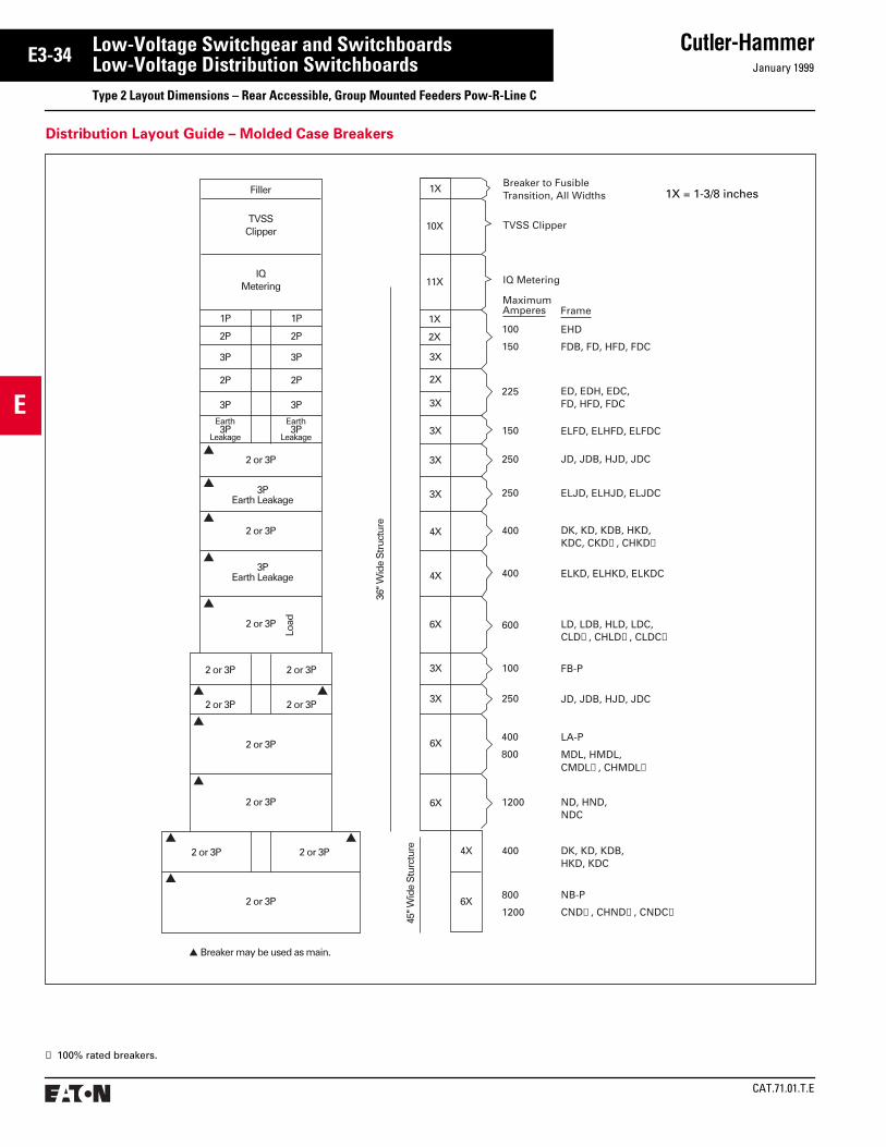
CAT.71.01.T.E
Cutler-HammerJanuary 1999
E
E3-34 Low-Voltage Switchgear and SwitchboardsLow-Voltage Distribution SwitchboardsType 2 Layout Dimensions – Rear Accessible, Group Mounted Feeders Pow-R-Line C
➀ 100% rated breakers.
1X
2X
▲
1P 1P
2P 2P
3P 3P
2P 2P
3P 3P
2 or 3P
Filler
TVSSClipper
2 or 3P
2 or 3P
Load
2 or 3P 2 or 3P
2 or 3P 2 or 3P
2 or 3P
2 or 3P
2 or 3P 2 or 3P
2 or 3P
▲ ▲
▲
▲
▲ ▲
▲
▲
▲
▲ Breaker may be used as main.
45" W
ide
Stu
rctu
re
36" W
ide
Str
uctu
re
1X
11X
3X
2X
3X
3X
4X
6X
3X
3X
6X
6X
4X
6X
IQMetering
Earth3P
Leakage
Earth3P
Leakage
3PEarth Leakage
▲
3PEarth Leakage
▲
10X
3X
3X
4X
FrameMaximumAmperes
600
1200
400
225
150
250
250
400
400
100
250
800
1200
Breaker to FusibleTransition, All Widths
TVSS Clipper
EHD
FDB, FD, HFD, FDC
ED, EDH, EDC,FD, HFD, FDC
JD, JDB, HJD, JDC
DK, KD, KDB, HKD,KDC, CKD➀, CHKD➀
LD, LDB, HLD, LDC,CLD➀, CHLD➀, CLDC➀
FB-P
JD, JDB, HJD, JDC
LA-P
MDL, HMDL,CMDL➀, CHMDL➀
ND, HND,NDC
DK, KD, KDB,HKD, KDC
NB-P
CND➀, CHND➀, CNDC➀
IQ Metering
ELFD, ELHFD, ELFDC
ELJD, ELHJD, ELJDC
ELKD, ELHKD, ELKDC
100
150
400
800
Distribution Layout Guide – Molded Case Breakers
1X = 1-3/8 inches
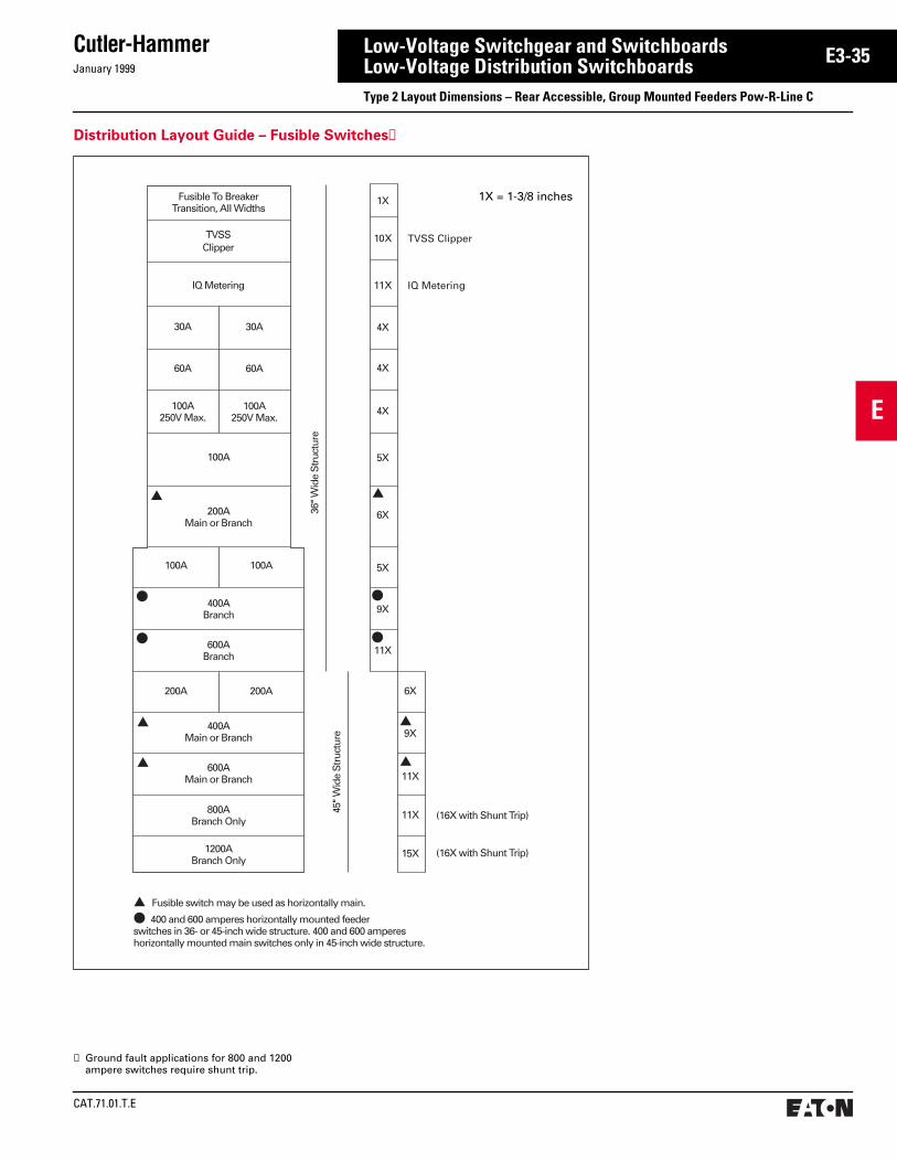
January 1999
Cutler-Hammer
CAT.71.01.T.E
E
E3-35Low-Voltage Switchgear and SwitchboardsLow-Voltage Distribution SwitchboardsType 2 Layout Dimensions – Rear Accessible, Group Mounted Feeders Pow-R-Line C
Distribution Layout Guide – Fusible Switches➀
36" W
ide
Str
uctu
re
Fusible To BreakerTransition, All Widths
100A250V Max.
▲
●
●
▲
▲
●
●
▲
▲
100A250V Max.
60A 60A
30A 30A
100A
200AMain or Branch
100A 100A
400ABranch
600ABranch
400AMain or Branch
800ABranch Only
600AMain or Branch
1200ABranch Only
200A 200A
45" W
ide
Str
uctu
re
1X
4X
4X
4X
5X
6X
5X
9X
11X
6X
9X
11X
11X
15X (16X with Shunt Trip)
(16X with Shunt Trip)
▲ Fusible switch may be used as horizontally main.
● 400 and 600 amperes horizontally mounted feeder switches in 36- or 45-inch wide structure. 400 and 600 amperes�horizontally mounted main switches only in 45-inch wide structure.
▲
TVSSClipper
IQ Metering11XIQ Metering
TVSS Clipper10X
1X = 1-3/8 inches
➀ Ground fault applications for 800 and 1200 ampere switches require shunt trip.

CAT.71.01.T.E
Cutler-HammerJanuary 1999
E
E3-36 Low-Voltage Switchgear and SwitchboardsLow-Voltage Distribution SwitchboardsType 2 Layout Dimensions – Rear Accessible Switchboards Pow-R-Line C
D36, 45
22XPanelSpace
Optional GFP
●
●
●
DW
Optional GFP
●
DW
W(Front)
66
21⁄2
21⁄2
D
CCClear Area➁
➂
Figure 1. Figure 2. Figure 3.
Floor Plan
Individually Mounted Feeder Devices
Dimensions (inches) for Estimating Purposes Only.
Dimensions for Figures 1 and 2Structure width to be determined by device requiring widest structure.
FeederDevice
Max.AmpRat-ing
ZeroSequenceGFP
No GFP or With IntegralGFP
Min.CableSpaceCC(Inch-es)
Min.Width(W)
Min.Depth(D)
Min.Width(W)
Min.Depth(D)
Fixed Mounted Devices
Molded Case Breakers
RD, RDCRD, RDC RD, RDC
160020002500
303030
484854
262626
484848
121212
100% Rated Power Circuit Breaker
Magnum DSMagnum DSMagnum DSMagnum DSMagnum DS
800
1200
1600
2000
2500
30
30
30
30
36
48
48
48
48
54
26
26
26
26
36
48
48
48
48
48
12
12
12
12
12
100% Rated Electric Trip Bolted Pressure Switches
CBC-800CBC-1200CBC-1600CBC-2000CBC-2500
8001200160020002500
3636363645
4848484854
3636363645
4848484848
1212121212
100% Rated Manual Bolted Pressure Switches
Not Available With Ground Fault Protection
QA-800QA-1200QA-1600QA-2000QA-2500
8001200160020002500
. . .
. . .
. . .
. . .
. . .
. . .
. . .
. . .
. . .
. . .
3030303036
4848484848
1212121212
➀ Clear area assumes no floor channels used under front or rear frame members.
➁ For Fig. 2 width will be 36 inches or 45 inchesdepending on size of panel mounting devices. Refer to page E3-33.
➂ When using top mounted (bottom feed) inverted bolted switches, verify acceptance with code authorities.
See pages E3-33 to E3-35 for layout of distribution sections.
See pages E3-39 and E3-40 for outdoor rainproof enclosures.
Top mounted pull boxes are available with heights of 12, 18, 24, and 30 inches.
Dimensions for Figure 3
FeederDevice
Max.AmpRating
No GFP or With Integral GFP
Min.CableSpaceCC(Inches)
Min.Width(W)
Min.Depth(D)
Fixed Mounted Devices
100% Rated Power Circuit Breaker
Magnum DS 800 30 48 12
100% Rated Manual Bolted Pressure Switches
Not Available With Ground Fault Protection
QA-800 800 30 48 12
➃ Clearance from walls (on boards that are not rear accessible) should be a minimum of 1/2 inch for indoor boards. For boards used in outdoor orwet locations the clearance should be no lessthan 6 inches.

January 1999
Cutler-Hammer
CAT.71.01.T.E
E
E3-37Low-Voltage Switchgear and SwitchboardsLow-Voltage Distribution SwitchboardsType 2 Layout Dimensions – For OPTIM Applications
50X Sectionused onlywhen BIMis locatedin mainsection orwhen BIMis notrequired
➀50X
VerticalPanelSpace
ForDevices
BreakerInterfaceModule
40XVerticalPanelSpace
ForDevices
➃
Power Supply
36W45W
90
36D Min. 36D Min.36W45W
See Section B4.
Figure 7.
For 800-4000 amperes: Incoming cable or busway enters top or bottom (rear) of any section.
➀ 50X distribution chassis can be used when main section accommodates location of breaker inter-face module, or BIM, is mounted above 40X chassis in another structure. Refer to auxiliary distribution for alternate BIM location below.
➁ Power Supply is provided for OPTIM trip units; maximum 25 breakers per power supply.
➂ When a utility compartment other than a NEMA compartment with an individually mounted main is required, see Figure 5 for mounting location of the BIM and associated components.
➃ BIM PROVISION on all 40X distribution sections; (1) BIM supports up to 50 devices. BIM may be located in main section to utilize 50X chassis.
Floor Plan
Front Accessible Feeder Sections
➄ Clear area assumes no floor channels used under bottom frame.
➅ Clearance from walls (on boards that are not rear accessible) should be a minimum of 1/2 inch for indoor boards. For boards used in outdoor orwet locations the clearance should be no lessthan 6 inches.
Rear Accessible Main Sections➀
2.25
D
3 3
36W-45W
10Clear Area
➄
Cross Bus
Incoming Conduits
WW W
PNL'BD PNL'BD PNL'BD
36Min.
30" HighCover
BIM➁➂12
33
90
Door
Main
Figure 1.Any Main
Top Entry or with UGPS
30DMin.
UGPS
3" High Cover
Figure 2.K, L, M, N, R, and APCB
Main Breaker
3" High Cover12" High
Door
BIM➁➂
30
W
15
90 Main
30" HighBlank or ColdSequenceNEMA CT Compt. 30D
Min.
Figure 3.Bolted Pressure
Main Switch
9" High Cover
DoorBIM➁➂
30
12
9
3990 Bolted PressureSwitch
30" HighBlank or ColdSequenceNEMA CT Compt. 30D
Min.
Figure 4.Main
Hot Sequence NEMA Utility
3" High Cover
6" High Cover
Door BarrierBIM➁➂
39
12
3
6
3090
Hot SequenceNEMA Utility
Main
30DMin.
W
Figure 2. Dimensions
Device Frame “W” Min. Width Sect.
KD 30
LD 30
MD 36
ND 36
RD 36
APCB 800-2000A 36
APCB 2500-3000A 45
APCB 4000A 51
FixedMtd.Only
APCB = AIr Power Circuit BreakerType Magnum DS or DS
Figure 5. Figure 6.

CAT.71.01.T.E
Cutler-HammerJanuary 1999
E
E3-38 Low-Voltage Switchgear and SwitchboardsLow-Voltage Distribution SwitchboardsType 2 Layout Dimensions – Rear Accessible OPTIM Switchboards Group Mounted Feeder Devices
1P 1P
FD, HFD, FDCED, EDH, EDC
JD, HJD, JDC
LD, HLD, LDC,CLD➀, CHLD➀
JD, HJD, JDC
FB-P
LA-P
OPTIM Trip Unit➂See section G3.
2P 2P
1X
➁
➁
➁
➁
2X
3X
2X
4X
8X
3X
3X
6X
8X
4X
3P 3P
2P 2P
3P
2 or 3P
2 or 3P
2 or 3P
2 or 3P 2 or 3P
2 or 3P
2 or 3P
2 or 3P
2 or 3P 2 or 3P
36/4
5" W
ide
Str
uct
ure
Rea
r A
cces
s
2 or 3P
Load
3P
40X/50XAvailable
DistributionSpace
6X
OPTI
M
6X
OPTI
M
KD, HKD, KDC,CKD, CHKD
MaximumAmperes Frame
225➀
250➀
600
250➀
100➀
400➀
400
EHD
FD, HFD, FDC
100➀
150➀
Earth3P
Leakage
Earth3P
Leakage
3PEarth Leakage
3PEarth Leakage
3X
3X
3X
3X
4X
ND, HND,NDC➃
OPTIM Trip Unit➂See section G3.
1200
KD, HKD, KDC➃400➀
ELFD, ELHFD, ELFDC150➀
ELJD, ELHJD, ELJDC250
ELKD, ELHKD, ELKDC400➀
➃
OPTI
M
OPTIM Trip Unit➂See section G3.
MDL, HMDL, CMDL, CHMDL6X2 or 3P 800➁
Refer to page G3-37 for additional breaker interface module locations when a utility compartment is not required.
Main Lugs are accessible from rear of switch-board and do not require any panel space.
Optimizer and instruction manual supplied with each switchboard line up. (Metal mounting frame included.)
Hand-Held Optimizer (programming unit) See section G3.
Seismic Qualified.
Distribution Layout Guide – Molded Case Breakers
➀ Non OPTIM, Available with Energy Sentinel.➁ All breakers with residual ground fault (including
provisions) require neutral sensors.➂ Power Supply is provided for OPTIM trip units;
maximum 25 breakers per power supply.➃ Requires 45-inch wide structure for 100% ND and
twin mounted KD breakers.

January 1999
Cutler-Hammer
CAT.71.01.T.E
E
E3-39Low-Voltage Switchgear and SwitchboardsLow-Voltage Distribution SwitchboardsType 2 Layout Dimensions – Rear Accessible, Group Mounted Feeder Outdoor Enclosures Pow-R-Line C
Non-Walk-in With Flat Roof
Dimensions (inches) for Estimating Purposes Only.
Switchboard IndoorStructure Depth
Non-Walk-in Enclosure Depth
24303648 (Minimum for XFMR connection)
37434961
Enclosure Depth
Swbd. Struc.Depth
Front ofPRL C InnerStructure
44.00
22.00
20.00
2.125
4.50 1.25
StructureWidth
‘A’To
Floor
Transition ➀
5.00
90.70
2.15
➁
12.81Structure Width20.00
17.37
➁
➀➀
Dimension ‘A’
0-2500 kVA Transformer 55.00
2501-5000 kVA Transformer 61.00
➀ 20-inch wide structure always required when throat connecting to other equipment. Standard transformer throat connection, 48-inch deep minimum.
➁ Standard busway entry/exit location, 36-inch deep minimum.

CAT.71.01.T.E
Cutler-HammerJanuary 1999
E
E3-40 Low-Voltage Switchgear and SwitchboardsLow-Voltage Distribution SwitchboardsType 2 Layout Dimensions – Rear Accessible, Group Mounted Feeder Outdoor Enclosures Pow-R-Line C
➁➁
Enclosure Depth
Swbd. Struc.Depth
44.00
22.00
24.00
2.125
4.50 2.25
5.00
92.945
.125End Trim
.125End Trim
Rear ofPRL C InnerStructure
Front ofPRL C
96.25
4.187
Top ofBus DuctChimney Cap
Rear of Enclosure20.50
12.81StructureWidth
Transition ➀Structure Width
20.00
‘A’To
Floor
➀ ➀
Dimensions (inches) for Estimating Purposes Only.
Switchboard IndoorStructure Depth
Non-Walk-in Enclosure Depth
24 (not available for XFMR)30 (not available for XFMR)36 (not available for XFMR)48 (minimum for XFMR connection)5466
414753657183
Non-Walk-in With Sloped Roof
Dimension ‘A’
0-2500 kVA Transformer 55.00
2501-5000 kVA Transformer 61.00
➀ 20-inch wide structure always required when throat connecting to other equipment. Standard transformer throat connection, 48-inch deep minimum.
➁ Standard busway entry/exit location, 36-inch deep minimum.
➂ Clearance from walls (on boards that are not rear accessible) should be a minimum of 1/2 inch for indoor boards. For boards used in outdoor orwet locations the clearance should be no lessthan 6 inches.
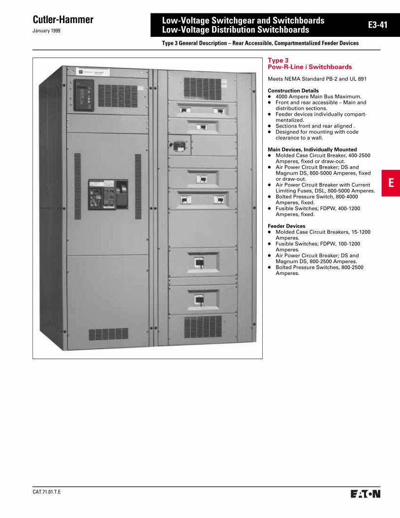
January 1999
Cutler-Hammer
CAT.71.01.T.E
E
E3-41Low-Voltage Switchgear and SwitchboardsLow-Voltage Distribution SwitchboardsType 3 General Description – Rear Accessible, Compartmentalized Feeder Devices
Type 3Pow-R-Line i Switchboards
Meets NEMA Standard PB-2 and UL 891
Construction Details● 4000 Ampere Main Bus Maximum.● Front and rear accessible – Main and
distribution sections.● Feeder devices individually compart-
mentalized.● Sections front and rear aligned .● Designed for mounting with code
clearance to a wall.
Main Devices, Individually Mounted● Molded Case Circuit Breaker, 400-2500
Amperes, fixed or draw-out.● Air Power Circuit Breaker; DS and
Magnum DS, 800-5000 Amperes, fixed or draw-out.
● Air Power Circuit Breaker with Current Limiting Fuses, DSL, 800-5000 Amperes.
● Bolted Pressure Switch, 800-4000 Amperes, fixed.
● Fusible Switches; FDPW, 400-1200 Amperes, fixed.
Feeder Devices● Molded Case Circuit Breakers, 15-1200
Amperes.● Fusible Switches; FDPW, 100-1200
Amperes.● Air Power Circuit Breaker; DS and
Magnum DS, 800-2500 Amperes.● Bolted Pressure Switches, 800-2500
Amperes.

CAT.71.01.T.E
Cutler-HammerJanuary 1999
E
E3-42 Low-Voltage Switchgear and SwitchboardsLow-Voltage Distribution SwitchboardsType 3 General Description – Rear Accessible, Compartmentalized Feeder Devices
Pow-R-Line i Construction Features
Distribution Section — Front View Distribution Section — Rear View
a Glass polyester circuit breaker compartment
b Insulated copper load side runbacksc Full length barrier isolating the cable
compartmentd Horizontal cross bus
e Tandem mounted circuit breakersthrough 400 amperes
f Isolating bus compartmentg Available zero sequence ground faulth Angled neutral connections
i A, B, C phase connectionsj Anti-turn lugsk Movable cable supportl Generous conduit space
a
b
d
e
fg
h
i
j
k
l
d
c
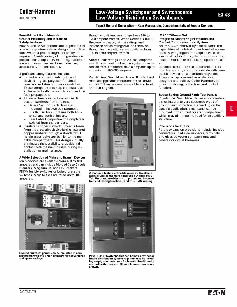
January 1999
Cutler-Hammer
CAT.71.01.T.E
E
E3-43Low-Voltage Switchgear and SwitchboardsLow-Voltage Distribution SwitchboardsType 3 General Description – Rear Accessible, Compartmentalized Feeder Devices
Pow-R-Line i Switchboards can help to provide for future distribution system requirements by includ-ing empty compartments for branch circuit break-ers and fusible devices. (Circuit breaker provisions shown.)
Ground fault test panels can be mounted in com-partments with the circuit breakers for convenience and space savings.
A standard feature of the Magnum DS Breaker, a main device, is the third generation Digitrip RMS Trip Unit that provides circuit protection, informa-tion and testing functions, and true RMS sensing.
Pow-R-Line i SwitchboardsGreater Flexibility and IncreasedSafety FeaturesPow-R-Line i Switchboards are engineered in a new compartmentalized design for applica-tions where a greater degree of safety is required. A wide variety of configurations is possible including utility metering, customer metering, main devices, branch devices, accessories, and enclosures.
Significant safety features include:● Individual compartments for branch
devices — glass polyester for circuit breakers and steel for fusible switches. These compartments help eliminate pos-sible contact with the main bus and reduce fault propagation.
● Three-section construction with each section barriered from the other.– Device Section. Each device is
mounted in its own compartment.– Bus Bar Section. Contains both hori-
zontal and vertical busses.– Rear Cable Compartment. Completely
isolated from the bus bars.● Insulated copper runback. Power is taken
from the protective device by the insulated copper runback through a standard full height glass polyester barrier to the rear cable compartment. This design virtually eliminates the possibility of accidental contact with the main busses during in-stallation or maintenance.
A Wide Selection of Main and Branch DevicesMain devices are available from 400 to 4000 amperes and can include Molded Case Circuit Breakers, Magnum DS and DS Breakers, FDPW fusible switches or bolted pressure switches. Main busses are rated up to 4000 amperes.
Branch circuit breakers range from 150 to 1200 ampere frames. When Series C Circuit Breakers are used, higher ratings and increased series ratings will be achieved. Branch fusible switches are available from 100 to 1200 ampere frames.
Short circuit ratings up to 200,000 amperes are UL listed and the bus bar system may be braced from a standard 65,000 amperes up to a maximum 100,000 amperes.
Pow-R-Line i Switchboards are UL listed and meet all applicable requirements of NEMA and NEC. They are rear accessible and front and rear aligned.
IMPACC/PowerNetIntegrated Monitoring Protection and Control Communications System An IMPACC/PowerNet System expands the capabilities of distribution and control assem-blies by tying together multiple devices in electrical distribution systems. From a central location (on-site or off-site), an operator uses a personal computer (master control unit) to monitor, control, and communicate with com-patible devices on a distribution system. These microprocessor-based devices, designed and built by Cutler-Hammer, per-form monitoring, protection, and control functions.
Space Saving Ground Fault Test PanelsPow-R Line i Switchboards can accommodate either integral or zero sequence types of ground fault protection. Depending on the specific application, a test panel can be mounted in the circuit breaker compartment which may eliminate the need for an auxiliary structure.
Provisions for FutureFuture expansion provisions include line side connectors, load side runbacks, terminals, and glass polyester compartments and covers (for circuit breakers).

CAT.71.01.T.E
Cutler-HammerJanuary 1999
E
E3-44 Low-Voltage Switchgear and SwitchboardsLow-Voltage Distribution SwitchboardsType 3 Layout Dimensions – Rear Accessible, Compartmentalized Feeders Pow-R-Line i
Main Structures – With Special Utility CT Compartments and/or Main Devices
Dimensions (inches) for Estimating Purposes Only.
Dimensions for Figures 1-4 “W” or “D” of structure is determined by the dimensions of the utility compartment or main device – whichever is greater. For main device dimensions see page E3-51. N/A = Not Applicable
Power CompanyCompartments
MeteringSequence
Rear Accessible
Figure 1 Figure 2 Figure 3 Figure 4
W D D D CC D CC
Atlantic City Electric Hot
800A1200A1600-2000A2500-4000A
36364545
36484848
36484848
36484848
6 61212
N/AN/AN/AN/A
. . . .
. . . .
. . . .
. . . .
Baltimore Gas and Electric➅ Hot
800A1200-2500A3000-4000A
36/45➅36/45➅45➅
36/30➅36/30➅30➅
36/30➅36/30➅30➅
➀➀➀
➀➀➀
N/AN/AN/A
. . . .
. . . .
. . . .
Boston Edison Cold
800-1600A2000-2500A3000-4000A
363636➃
N/AN/AN/A
N/AN/AN/A
N/AN/AN/A
. . . .
. . . .
. . . .
303636➃
61212➃
Central Hudson Gas and Electric Hot➇/Cold ➄ ➄ ➄ ➄ ➄ N/A . . . .
Central Vermont Hot ➄ ➄ ➄ ➄ ➄ N/A N/A
Cincinnati Gas and Electric Hot
800A1000A1200-2000A2500-4000A
36364545
30303636
30303636
36364848
6 61212
N/AN/AN/AN/A
. . . .
. . . .
. . . .
. . . .
Commonwealth Edison Hot
400-1000A1200-2000A2500-4000A
363636
364848
364848
364848
6 612
N/AN/AN/A
. . . .
. . . .
. . . .
Bottom Feed Top Feed Bottom or Top Feed Bottom or Top Feed
Figure 1. Figure 2. Figure 3. Figure 4. (Cold Sequence)
W
ClearArea
➆
33
21⁄2
21⁄2
D
Blank
UtilityCompartmentHot Sequence
WD
●
●
Blank
UtilityCompartmentHot Sequence
WD
Main
WD
UtilityCompartmentHot Sequence
Main2500AmpMax.➃
WD
UtilityCompartment
ColdSequence
W33
CCClear Area➆
Floor PlanFigures 3. and 4.
Floor PlanFigure 1.
➀ Refer to Cutler-Hammer.➁ For limiter lugs or more than six (6) mechanical
lugs per phase, a separate pull section is required.➂ For limiter lugs or more than six (6) mechanical
lugs per phase, a 12-inch pull box is required.➃ Cold sequence: 3000A or 4000A main device must
be mounted in separate structure. Rear accessible designs refer to page E3-50, Figs. 1 and 2. The util-ity compartment will then be housed in the bot-tom of the second structure. Branch devices or customer metering can then be mounted in re-maining top half of utility compartment structure.
➄ Dimensions are the same as standard NEMA utility compartments, refer to page E3-50.
➅ For BG&E, the utility compartment is mounted in the bottom for Fig. 1 and top for Fig. 2. For bottom feed (Fig. 1); up to 2500 amperes, the main is mounted in top. For 3000A and 4000A bottom feed, the main is in a separate structure. For top feed (Fig. 2), maximum amperes is 4000A and the main is mounted in the bottom.
➆ Clear area assumes no floor channels used under bottom frame.
➇ For special applications approved by the utility.➈ Clearance from walls (on boards that are not rear
accessible) should be a minimum of 1/2 inch for indoor boards. For boards used in outdoor orwet locations the clearance should be no lessthan 6 inches.

January 1999
Cutler-Hammer
CAT.71.01.T.E
E
E3-45Low-Voltage Switchgear and SwitchboardsLow-Voltage Distribution SwitchboardsType 3 Layout Dimensions – Rear Accessible, Compartmentalized Feeders Pow-R-Line i
➀ Refer to Cutler-Hammer.➁ For limiter lugs or more than six (6) mechanical
lugs per phase, a separate pull section is required.➂ For limiter lugs or more than six (6) mechanical
lugs per phase, a 12-inch pull box is required.➃ Cold sequence: 3000A or 4000A main device must
be mounted in separate structure. Rear accessible designs refer to page E3-50, Figs. 1 and 2. The util-
ity compartment will then be housed in the second structure. Branch devices or customer metering can then be mounted in remaining half of utility compartment structure.
➄ Dimensions are the same as standard NEMA utility compartments, refer to page E3-50.
➅ For BG&E, the utility compartment is mounted in the bottom for Fig. 1 and top for Fig. 2. For bottom
feed (Fig. 1); up to 2500 amperes, the main is mounted in top. For 3000A and 4000A bottom feed, the main is in a separate structure. For top feed (Fig. 2), maximum amperes is 4000A and the main is mounted in the bottom.
➆ Clear area assumes no floor channels used under bottom frame.
➇ For special applications approved by the utility.
Main Structures – With Special Utility CT Compartments and/or Main Devices, Continued
Dimensions (inches) for Estimating Purposes Only.
Dimensions for Figures 1-4, Continued, “W” or “D” of structure is determined by the dimensions of the utility compartment or main device – whichever is greater. For main device dimensions see page E3-51. N/A = Not Applicable
Power CompanyCompartments
MeteringSequence
Rear Accessible
Figure 1 Figure 2 Figure 3 Figure 4
W D D D CC D CC
Connecticut Light and Power Hot/Cold➇
800-1200A1600-2000A2500-4000A
➄3636/45
➄3036
➄3036
➄4848
➄N/AN/A
➄4848➃
➄1212➃
Consolidated Edison Hot
800A (Spec. 298)1200A-1600A (Spec. 298) 1200-2000A (Spec. 377)2500-4000A (Spec. 377)
38384545
30303636
30➀30➀36➀36➀
36364848
6 61212
N/AN/AN/AN/A
. . . .
. . . .
. . . .
. . . .
Detroit Edison Hot
800A1200-2000A2500-4000A
363645
363648
363648
363648
6 612
N/AN/AN/A
. . . .
. . . .
. . . .
Florida Power and Light Hot ➄ ➄ ➄ ➄ ➄ N/A . . . .
Georgia Power Co. Hot ➄ ➄ ➄ ➄ ➄ N/A . . . .
Indianapolis Power Co. Hot/Cold➇
800A1200-2000A2500-4000A
363636
363636
363636
484848
121212
484848➃
121212➃
Jersey Central Power Hot/Cold➇
800A1200-2000A2500-4000A
➄4545
➄4848
➄4848
➄4848
➄1212
➄4848➃
➄1212➃
Kansas City Power and Light Hot ➄ ➄ ➄ ➄ ➄ N/A . . . .
Long Island Light Co. Hot
800-1200A1600-2000A2500-4000A
384545
243636
243636
364848
61212
N/AN/AN/A
. . . .
. . . .
. . . .
Louisville Gas and Electric Hot
800A1200-2000A2500-3000A
364545
484848
484848
484848
61212
N/AN/AN/A
. . . .
. . . .
. . . .
Madison Gas and Electric Cold
800-1200A1600-2000A2500-3000A
363645
N/AN/AN/A
N/AN/AN/A
N/AN/AN/A
. . . .
. . . .
. . . .
363648➃
6 612➃
Massachusetts Electric Hot
800A1200-2000A2500-4000A
➄3636/45
➄3036
➄3036
➄3048
➄ 612
N/AN/AN/A
. . . .
. . . .
. . . .
Metropolitan Edison Hot ➄ ➄ ➄ ➄ ➄ N/A . . . .
Monongahela Power Hot 45 48 48 48 ➄ N/A . . . .
Naperville Hot ➄ ➄ ➄ ➄ ➄ N/A . . . .
Narragansett Hot
800A1200-2000A2500-4000A
➄3636/45
➄3036
➄3036
➄3648
➄ 612
N/AN/AN/A
. . . .
. . . .
. . . .

CAT.71.01.T.E
Cutler-HammerJanuary 1999
E
E3-46 Low-Voltage Switchgear and SwitchboardsLow-Voltage Distribution SwitchboardsType 3 Layout Dimensions – Rear Accessible, Compartmentalized Feeders Pow-R-Line i
➀ Refer to Cutler-Hammer.➁ For limiter lugs or more than six (6) mechanical
lugs per phase, a separate pull section is required.➂ For limiter lugs or more than six (6) mechanical
lugs per phase, a 12-inch pull box is required.➃ Cold sequence: 3000A or 4000A main device must
be mounted in separate structure. Rear accessible designs refer to page E3-50, Figs. 1 and 2. The util-ity compartment will then be housed in the sec-ond structure. Branch devices or customer metering can then be mounted in remaining half of utility compartment structure.
➄ Dimensions are the same as standard NEMA utility compartments, refer to page E3-50.
➅ For BG&E, the utility compartment is mounted in the bottom for Fig. 1 and top for Fig. 2. For bottom feed (Fig. 1); up to 2500 amperes, the main is mounted in top. For 3000A and 4000A bottom feed, the main is in a separate structure. For top feed (Fig. 2), maximum amperes is 4000A and the main is mounted in the bottom.
➆ Clear area assumes no floor channels used under bottom frame.
➇ For special applications approved by the utility.➈ Clearance from walls (on boards that are not rear
accessible) should be a minimum of 1/2 inch for indoor boards. For boards used in outdoor orwet locations the clearance should be no lessthan 6 inches.
Dimensions (inches) for Estimating Purposes Only.
Dimensions For Figures 1-4, Continued, “W” or “D” of structure is determined by the dimensions of the utility compartment or main device – whichever is greater. For main device dimensions see page E3-51. N/A = Not Applicable
Power CompanyCompartments
MeteringSequence
Rear Accessible
Figure 1 Figure 2 Figure 3 Figure 4
W D D D CC D CC
New York State Electric and Gas Cold
800-1200A1600-2000A2500-4000A
363645
N/AN/AN/A
N/AN/AN/A
N/AN/AN/A
. . . .
. . . .
. . . .
364848➃
6 6 6➃
Niagara Mohawk Cold
800-1200A1600-2000A2500-4000A
➄3636/45
N/AN/AN/A
N/AN/AN/A
N/AN/AN/A
. . . .
. . . .
. . . .
➄3636➃
➄ 6 6➃
Northeast Utilities Hot➇/Cold
800-1200A1600-2000A2500-4000A
➄3636/45
➄3648
➄3648
➄4848
➄1212
➄4848➃
➄1212➃
Northern States Power Hot
800-1200A1600-2000A2500-4000A
363636/45
303030/36
303030/36
363636/48
6 66/12
N/AN/AN/A
. . . .
. . . .
. . . .
Omaha Public Power Hot
1200-2000A2500-4000A
4545
3636
3636
4848
1212
N/AN/A
. . . .
. . . .
Orange and Rockland Hot ➄ ➄ ➄ ➄ ➄ N/A . . . .
Pennsylvania Power and Light Hot
800-4000A➀ 45 48➁ 48➂ 54 6 N/A . . . .
Philadelphia Electric Company Hot ➄ ➄ ➄ ➄ ➄ N/A . . . .
Main Structures – With Special Utility CT Compartments and/or Main Devices, Continued
Bottom Feed Top Feed Bottom or Top Feed Bottom or Top Feed
Figure 1. Figure 2. Figure 3. Figure 4.(Cold Sequence)
W
ClearArea
➆
33
21⁄2
21⁄2
D
Blank
UtilityCompartmentHot Sequence
WD
●
●
Blank
UtilityCompartmentHot Sequence
WD
Main
WD
UtilityCompartmentHot Sequence
Main2500AmpMax.➄
WD
UtilityCompartment
ColdSequence
W6
CCClear Area➆
6
Floor PlanFigure 1.
Floor PlanFigures 3. and 4.

January 1999
Cutler-Hammer
CAT.71.01.T.E
E
E3-47Low-Voltage Switchgear and SwitchboardsLow-Voltage Distribution SwitchboardsType 3 Layout Dimensions – Rear Accessible, Compartmentalized Feeders Pow-R-Line i
➀ Refer to Cutler-Hammer.➁ For limiter lugs or more than six (6) mechanical
lugs per phase, a separate pull section is required.➂ For limiter lugs or more than six (6) mechanical
lugs per phase, a 12-inch pull box is required.➃ Cold sequence: 3000A or 4000A main device must
be mounted in separate structure. Rear accessible designs refer to page E3-50, Figs. 1 and 2. The util-
ity compartment will then be housed in the sec-ond structure. Branch devices or customer metering can then be mounted in remaining half of utility compartment structure.
➄ Dimensions are the same as standard NEMA utility compartments, refer to page E3-50.
➅ For BG&E, the utility compartment is mounted in the bottom for Fig. 1 and top for Fig. 2. For bottom
feed (Fig. 1); up to 2500 amperes, the main is mounted in top. For 3000A and 4000A bottom feed, the main is in a separate structure. For top feed (Fig. 2), maximum amperes is 4000A and the main is mounted in the bottom.
➆ Clear area assumes no floor channels used under bottom frame.
➇ For special applications approved by the utility.
Main Structures – With Special Utility CT Compartments and/or Main Devices, Continued
Dimensions for Estimating Purposes Only.
Dimensions for Figures 1-4, Continued, “W” or “D” of structure is determined by the dimensions of the utility compartment or main device – whichever is greater. For main device dimensions see page E3-51. N/A = Not Applicable
Power CompanyCompartments
MeteringSequence
Rear Accessible
Figure 1 Figure 2 Figure 3 Figure 4
W D D D CC D CC
Potomac Electric Power Company Hot
800-2000A2500-4000A800-3000A
4000A
36363636
3036N/AN/A
N/AN/A3648
N/AN/AN/AN/A
. . . .
. . . .
. . . .
. . . .
N/AN/AN/AN/A
. . . .
. . . .
. . . .
. . . .
Public Service of Colo. Hot
800A1200-2000A2500-4000A
➄3645
➄3036
➄3036
➄3048
➄ 612
N/AN/AN/A
. . . .
. . . .
. . . .
Public Service Electric and Gas Hot
800A1200-2000A2500A3000A-4000A
36454545
30484848
30484848
36484848
6121212
N/AN/AN/AN/A
. . . .
. . . .
. . . .
. . . .
Public Service of New Hampshire Hot/Cold➇ ➄ ➄ ➄ ➄ ➄ N/A . . . .
Toledo Edison Cold ➄ ➄ ➄ ➄ ➄ N/A . . . .
Union Electric Hot
800-4000A ➄ ➄ ➄ ➄ ➄ N/A N/A
Virginia Power Company Hot
800A1200A1600-2000A2500-4000A
36364545
36363648
36363648
36364848
6 61212
N/AN/AN/AN/A
. . . .
. . . .
. . . .
. . . .
Wisconsin Electric Power Co. Hot
800A1200A1600-3000A4000A
36363645
30303636
30303636
36364848
6 61212
N/AN/AN/AN/A
. . . .
. . . .
. . . .
. . . .
Wisconsin Power and Light Hot
800A1200-2000A2500-3000A
363645
363636
363636
484848
121212
N/AN/AN/A
. . . .
. . . .
. . . .
Wisconsin Public Service Hot
1000-4000A 45 30 48 N/A . . . . N/A . . . .

CAT.71.01.T.E
Cutler-HammerJanuary 1999
E
E3-48 Low-Voltage Switchgear and SwitchboardsLow-Voltage Distribution SwitchboardsType 3 Layout Dimensions – Rear Accessible, Compartmentalized Feeders Pow-R-Line i
W
ClearArea
➀
33
21⁄2
21⁄2
D
●
Blank
UtilityCompartmentHot Sequence
WD
PullSection
UtilityCompartmentHot Sequence
Main
WD
●
W1
HPull Box
W1
ClearArea
➀
W
21⁄2
21⁄2
D
Main Structures – With West Coast Utility CT Compartments and/or Main Devices
Dimensions (inches) for Estimating Purposes Only.
Dimensions for Figures 1-2 “W” or “D” of structure is determined by the dimensions of the utility compartment or main device – whichever is greater. For main device dimensions see page E3-51. N/R = Not Required
Power CompanyCompartments
Front or Rear Accessible
Figure 1 Figure 2 (Top Feed)Top MtgPull Box
(Bottom Feed)PullSection
Width (W) Depth (D) Width (W) Depth (D) Height (H) Width (W1)
West Coast Utilities
E.U.S.E.R.C.
400-800A1000A1200A1600A2000A 2500A3000A4000A
3636384545515151
2424303030363636
3636383838383851
2424303030303036
N/R30363636363636
3036364545515151
S.C.E.
400A 600-800A1000A1200A1600A2000A2500A3000A4000A
363636384545. . .. . .. . .
242424303030. . .. . .. . .
363636383838383851
242424303030303036
N/RN/R30363636363636
303036364545515151
L.A.D.W.P.
400A 600-800A1000A1200A1600A2000A 2500A3000A4000A
363636384545. . .. . .. . .
242424303030. . .. . .. . .
363636383838383851
242424303030303036
➁➁➁➁➁➁➁➁➁
303036364545515151
➀ Clear area assumes no floor channels used under bottom frame.
➁ Refer to Cutler-Hammer.
Bottom Feed Bottom or Top Feed
Figure 1. Figure 2.
Floor PlanFigure 1.
Floor PlanFigure 2.
➂ Clearance from walls (on boards that are not rear accessible) should be a minimum of 1/2 inch for indoor boards. For boards used in outdoor orwet locations the clearance should be no lessthan 6 inches.
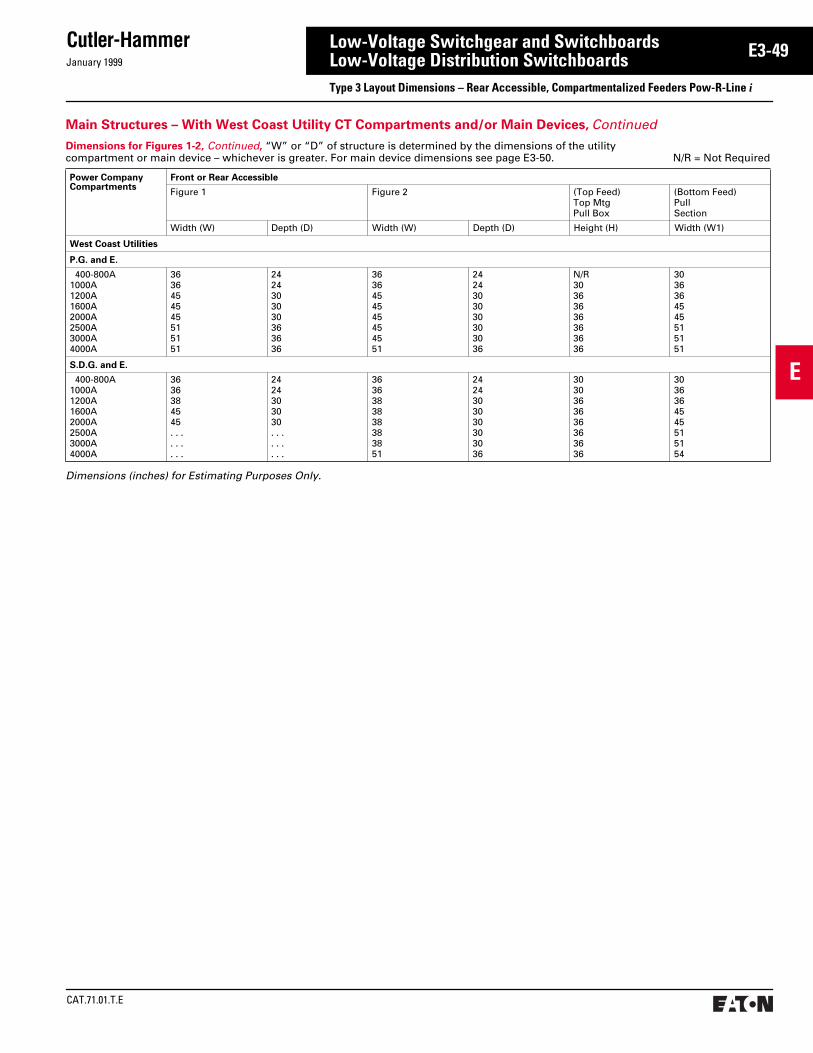
January 1999
Cutler-Hammer
CAT.71.01.T.E
E
E3-49Low-Voltage Switchgear and SwitchboardsLow-Voltage Distribution SwitchboardsType 3 Layout Dimensions – Rear Accessible, Compartmentalized Feeders Pow-R-Line i
Main Structures – With West Coast Utility CT Compartments and/or Main Devices, Continued
Dimensions (inches) for Estimating Purposes Only.
Dimensions for Figures 1-2, Continued, “W” or “D” of structure is determined by the dimensions of the utility compartment or main device – whichever is greater. For main device dimensions see page E3-50. N/R = Not Required
Power CompanyCompartments
Front or Rear Accessible
Figure 1 Figure 2 (Top Feed)Top MtgPull Box
(Bottom Feed)PullSection
Width (W) Depth (D) Width (W) Depth (D) Height (H) Width (W1)
West Coast Utilities
P.G. and E.
400-800A1000A1200A1600A 2000A 2500A3000A4000A
3636454545515151
2424303030363636
3636454545454551
2424303030303036
N/R30363636363636
3036364545515151
S.D.G. and E.
400-800A1000A1200A1600A2000A2500A3000A4000A
3636384545. . .. . .. . .
2424303030. . .. . .. . .
3636383838383851
2424303030303036
3030363636363636
3036364545515154

CAT.71.01.T.E
Cutler-HammerJanuary 1999
E
E3-50 Low-Voltage Switchgear and SwitchboardsLow-Voltage Distribution SwitchboardsType 3 Layout Dimensions – Rear Accessible, Compartmentalized Feeders Pow-R-Line i
Main Structure – With Standard (NEMA) Utility CT Compartments and/or Main Device
Cold Sequence UtilityHot Sequence Utility
Dimensions (inches) for Estimating Purposes Only.
Main DeviceDimensions for Figures 1-4
MainDevice
Max.AmpRating
Width(W)
Depth(D)
Min. CableSpace CC(Inches)
Fixed Mounted Devices
Molded Case Breakers Available
With Optional Integral GFP
KD, HKD, KDCLD, HLD, LDCND, HND, NDCRD, RDCRD, RDC RD, RDC
400 60012001600200025003000
36363636363645
48484848484848
12121212121212
100% Rated Molded Case Breakers
Available With Optional Integral GFP
CKD, CHKDCLD, HCLD, CLDCCND, CHND, CNDCCRD, CRDCCRD, CRDC
400 600
1200
16002000
3636
36
3636
48484848484848
12121212121212
TRI-PAC Fuse Type Current Limiting Breakers
LA-PNB-PPB-P
400 8001600
363636
484848
121212
MainDevice
Max.AmpRating
Width(W)
Depth(D)
Min. CableSpace CC(Inches)
Fixed Mounted Devices
100% Rated Power Circuit Breakers
Available With Optional Integral GFP
Magnum DS and DSMagnum DS and DSMagnum DS and DSMagnum DS and DSMagnum DS and DS
800
1600
2000
3200
4000
36
36
36
45
45
48
48
48
54/66
54/66
12
12
12
6/18
6/18
FDPW Fusible Switches
FDPW400FDPW600FDPW800FDPW1200
400 600 8001200
36363636
48484848
12121212
100% Rated Electric Trip Bolted Pressure Switches
Available With Optional GFP
CBC-800CBC-1200CBC-1600CBC-2000CBC-2500CBC-3000CBC-4000CBC-5000➁CBC-6000➁
80012001600200025003000400050006000
36363636454545
48484848484848
12121212121212
Refer to Cutler-HammerRefer to Cutler-Hammer
100% Rated Manual Bolted Pressure Switches
Not Available With Ground Fault Protection
QA-800QA-1200QA-1600QA-2000QA-2500QA-3000QA-4000QA-5000➁QA-6000➁
80012001600200025003000400050006000
36363636454545
48484848484848
12121212121212
Refer to Cutler-HammerRefer to Cutler-Hammer
MainDevice
Max.AmpRating
Width(W)
Depth(D)
Min. CableSpace CC(Inches)
Draw-out Mounted Devices
100% Rated Power Circuit Breakers
Available With Optional Integral GFP
Magnum DS and DSMagnum DS and DSMagnum DS and DSMagnum DS and DSMagnum DS and DSMagnum DS and DSMagnum DS and DSMagnum DS and DSMagnum DS and DSMagnum DS and DSMagnum DS and DS
800
1600
2000
3200
4000
36
36
36
36
36
45
45
45
45
45
45
54
66
54
66
54
66
66
66
66
66
66
6
12
6
12
6
18
Refer to Cutler-Hammer
Optional GFP
UtilityCompartmentHot Sequence
Main
WD
●
90
Optional GFP
UtilityCompartmentHot Sequence
Main
WD
●
90
Optional GFP
Main ➂
WD
OptionalCustomerMetering
UtilityCompartment
ColdSequence
Optional GFP
WD
OptionalCustomerMetering
UtilityCompartment
ColdSequence
Main ➂W
(Front)
66
21⁄2
21⁄2
D
Clear Area➀
CC
Refer to pages E3-44 to E3-49 for dimensions on special utility CT compartments.
See pages E3-52 to E3-53 for layout of distri-bution sections.
See pages E3-57 and E3-58 for outdoor rain-proof enclosures.
Top mounted pull boxes are available with heights of 12, 18, 24, and 30 inches.
Figure 1. Figure 2. Figure 3. Figure 4.
Top Entrance Bottom EntranceFloor PlanTop Feed Bottom Feed
➀ Clear area assumes no floor channels used under front or rear frame members.
➁ Not UL listed.➂ IQ meter mounted to disconnect door as an alter-
nate location. (For K, L, M, N, and R frames and fixed mounted power circuit breakers.)
➃ Clearance from walls (on boards that are not rear accessible) should be a minimum of 1/2 inch for indoor boards. For boards used in outdoor orwet locations the clearance should be no lessthan 6 inches.

January 1999
Cutler-Hammer
CAT.71.01.T.E
E
E3-51Low-Voltage Switchgear and SwitchboardsLow-Voltage Distribution SwitchboardsType 3 Layout Dimensions – Rear Accessible, Compartmentalized Feeders Pow-R-Line i
Optional GFP
Main
WD
●
OptionalCustomerMetering➁
90
Optional GFP
Main
WD
●
OptionalCustomerMetering➁
66
21⁄2
21⁄2
D
Clear Area➀
CC
W(Front)
Optional GFP
WD
●
OptionalCustomerMetering➁
90Main
➃
Main Structure – With Customer Metering and/or Main Device
Top EntranceBottom Mounted
Main Load Cross Bus
See pages E3-52 to E3-53 for layout of distri-bution sections.
Dimensions (inches) for Estimating Purposes Only.
Main DeviceDimensions for Figures 1-3
MainDevice
Max.AmpRat-ing
Min. Width (W) Min.Depth(D)
Min.CableSpaceCC(Inches)
ZeroSe-quenceGFP
IntegralGFP orW/NoGFP
Fixed Mounted Devices
Molded Case Breakers
Available With Optional Integral GFP
KD, HKD, KDCLD, HLD, LDCND, HND, NDCRD, RDCRD, RDC RD, RDC
400 6001200160020002500
303030303030
262626262626
484848484848
181818181818
100% Rated Molded Case Breakers
Available With Optional Integral GFP
CKD, CHKDCLD, HCLD, CLDCCND, CHND, CNDCCRD, CRDCCRD, CRDC
400 600
1200
16002000
3030
30
3030
2626
26
2626
4848
48
4848
1818
12
1818
TRI-PAC Fuse Type Current Limiting Breakers
LA-P➃NB-P➃PB-P➃
400 8001600
303030
262626
484848
181818
MainDevice
Max.AmpRat-ing
Min. Width (W) Min.Depth(D)
Min.CableSpaceCC(Inches)
ZeroSe-quenceGFP
IntrgralGFP orW/NoGFP
Fixed Mounted Devices
100% Rated Power Circuit Breakers
Available With Optional Integral GFP
Magnum DS and DSMagnum DS and DSMagnum DS and DSMagnum DS and DSMagnum DS and DS
800
1600
2000
3200
4000
36
36
36
36
45
36
36
36
36
45
48
48
48
54
54
12
12
12
6
6
FDPW Fusible Switches
FDPW400FDPW600FDPW800FDPW1200
400 600 8001200
30303030
26263030
48484848
18181818
100% Rated Electric Trip Bolted Pressure Switches
Available With Optional GFP
CBC-800CBC-1200CBC-1600CBC-2000CBC-2500CBC-3000CBC-4000CBC-5000➂CBC-6000➂
80012001600200025003000400050006000
36363636454545
36363636454545
48484848484848
18181818121212
Refer to Cutler-HammerRefer to Cutler-Hammer
100% Rated Manual Bolted Pressure Switches
Not Available With Ground Fault Protection
QA-800QA-1200QA-1600QA-2000QA-2500QA-3000QA-4000QA-5000➂QA-6000➂
80012001600200025003000400050006000
N/AN/AN/AN/AN/AN/AN/A
30303030364545
48484848484848
18181818121212
Refer to Cutler-HammerRefer to Cutler-Hammer
MainDevice
Max.AmpRat-ing
Min. Width (W) Min.Depth(D)
Min.CableSpaceCC(Inches)
ZeroSe-quenceGFP
IntrgralGFP orW/NoGFP
Draw-out Mounted Devices
100% Rated Power Circuit Breakers
Available With Optional Integral GFP
Magnum DS and DSMagnum DS and DSMagnum DS and DSMagnum DS and DSMagnum DS and DSMagnum DS and DSMagnum DS and DSMagnum DS and DSMagnum DS and DSMagnum DS and DSMagnum DS and DS
800
1600
2000
3200
4000
36
36
36
36
36
45
45
45
45
45
45
36
36
36
36
36
45
45
45
45
45
45
54
66
54
66
54
66
66
66
54
66
66
6
12
6
12
6
18
12
N/A
12
12
N/A
Bottom EntranceBottom Mounted
Main Load Cross Bus
Bottom EntranceMid Mounted Main
Load Cross Bus
Floor Plan
See pages E3-57 and E3-58 for outdoor rainproof enclosures.
Top mounted pull boxes are available with heights of 12, 18, 24, and 30 inches.
Figure 1. Figure 2. Figure 3.
➀ Clear area assumes no floor channels used under front or rear frame members.
➁ Customer metering with IQ meter requires 30-inch minimum width.
➂ Not UL listed.➃ Not available with bottom fed Tri-Pac breaker.➄ IQ meter mounted to disconnect door as an alter-
nate location. When Series C K, L, M, N, and R fixed mounted frames and ACB fixed mounted breakers are used.
➅ Clearance from walls (on boards that are not rear accessible) should be a minimum of 1/2 inch for indoor boards. For boards used in outdoor orwet locations the clearance should be no lessthan 6 inches.
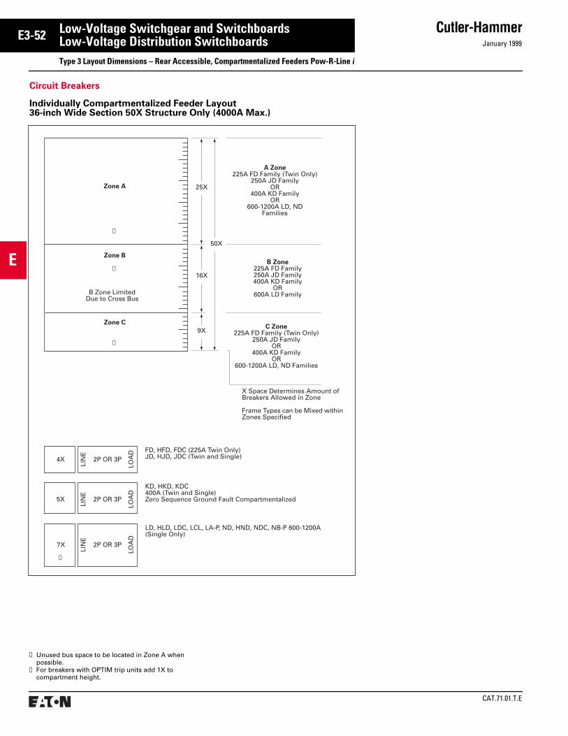
CAT.71.01.T.E
Cutler-HammerJanuary 1999
E
E3-52 Low-Voltage Switchgear and SwitchboardsLow-Voltage Distribution SwitchboardsType 3 Layout Dimensions – Rear Accessible, Compartmentalized Feeders Pow-R-Line i
➀ Unused bus space to be located in Zone A when possible.
➁ For breakers with OPTIM trip units add 1X to compartment height.
Circuit Breakers
Individually Compartmentalized Feeder Layout 36-inch Wide Section 50X Structure Only (4000A Max.)
A Zone225A FD Family (Twin Only)
250A JD FamilyOR
400A KD FamilyOR
600-1200A LD, NDFamilies
Zone A 25X
16X
9X
50X
➀
Zone B
➀
B Zone LimitedDue to Cross Bus
➀
Zone C
B Zone225A FD Family250A JD Family400A KD Family
OR600A LD Family
C Zone225A FD Family (Twin Only)
250A JD FamilyOR
400A KD FamilyOR
600-1200A LD, ND Families
X Space Determines Amount ofBreakers Allowed in Zone
Frame Types can be Mixed withinZones Specified
2P OR 3P
LOA
D
LIN
E
4XFD, HFD, FDC (225A Twin Only)JD, HJD, JDC (Twin and Single)
2P OR 3P
LOA
D
LIN
E
5X
KD, HKD, KDC400A (Twin and Single)Zero Sequence Ground Fault Compartmentalized
2P OR 3P
LOA
D
LIN
E
7X
➁
LD, HLD, LDC, LCL, LA-P, ND, HND, NDC, NB-P 600-1200A(Single Only)

January 1999
Cutler-Hammer
CAT.71.01.T.E
E
E3-53Low-Voltage Switchgear and SwitchboardsLow-Voltage Distribution SwitchboardsType 3 Layout Dimensions – Rear Accessible, Compartmentalized Feeders Pow-R-Line i
Zone A 25X
16X
9X
50X
➀
Zone B
➀
B Zone LimitedDue to Cross Bus
➀
Zone C
A Zone200AOR
400/600AOR
800/1200A
B Zone225, 250, 400, 600A
C Zone200A
X Space DeterminesAmount of SwitchesAllowed in Zone
Switch Types can be Mixedwithin Zones Specified
No Twin Mounted Switches
5XZero Sequence Ground Fault Compartment
200A TwinBranch6X
240V, 600V, 250Vdc
400 Branch9X
240V, 600V, 250Vdc
600/800ABranch11X
240V, 600V
1200A Branch15X
240V, 600V
GF Relays
FDPW Fusible Switches
Individually Compartmentalized Feeder Layout 36-inch Wide Section 50X Structure Only (4000A Max.)
➀ Unused bus space to be located in Zone A when possible.
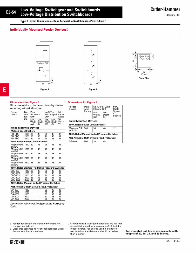
CAT.71.01.T.E
Cutler-HammerJanuary 1999
E
E3-54 Low-Voltage Switchgear and SwitchboardsLow-Voltage Distribution SwitchboardsType 3 Layout Dimensions – Rear Accessible Switchboards Pow-R-Line i
DW
Optional GFP
●
W(Front)
66
21⁄2
21⁄2
D
CCClear Area➁
DW
Floor Plan
Individually Mounted Feeder Devices➀
Dimensions (inches) for Estimating Purposes Only.
Dimensions for Figure 1Structure width to be determined by device requiring widest structure.
FeederDevice
Max.AmpRat-ing
ZeroSequenceGFP
No GFP or With IntegralGFP
Min.CableSpaceCC(Inch-es)
Min.Width(W)
Min.Depth(D)
Min.Width(W)
Min.Depth(D)
Fixed Mounted Devices
Molded Case Breakers
RD, RDCRD, RDC RD, RDC
160020002500
303030
484854
262626
484848
121212
100% Rated Power Circuit Breaker
Magnum DS and DSMagnum DS and DSMagnum DS and DSMagnum DS and DSMagnum DS and DS
800
1200
1600
2000
2500
30
30
30
30
36
48
48
48
48
54
26
26
26
26
36
48
48
48
48
48
12
12
12
12
12
100% Rated Electric Trip Bolted Pressure Switches
CBC-800CBC-1200CBC-1600CBC-2000CBC-2500
8001200160020002500
3636363645
4848484854
3636363645
4848484848
1212121212
100% Rated Manual Bolted Pressure Switches
Not Available With Ground Fault Protection
QA-800QA-1200QA-1600QA-2000QA-2500
8001200160020002500
. . .
. . .
. . .
. . .
. . .
. . .
. . .
. . .
. . .
. . .
3030303036
4848484848
1212121212
➀ Feeder devices are individually mounted, not compartmentalized.
➁ Clear area assumes no floor channels used under front or rear frame members. Top mounted pull boxes are available with
heights of 12, 18, 24, and 30 inches.
Dimensions for Figure 2
FeederDevice
Max.AmpRating
No GFP or With Integral GFP
Min.CableSpaceCC(Inches)
Min.Width(W)
Min.Depth(D)
Fixed Mounted Devices
100% Rated Power Circuit Breaker
Magnum DS and DS
800 30 48 12
100% Rated Manual Bolted Pressure Switches
Not Available With Ground Fault Protection
QA-800 800 30 48 12
Figure 2Figure 1
➂ Clearance from walls (on boards that are not rear accessible) should be a minimum of 1/2 inch for indoor boards. For boards used in outdoor orwet locations the clearance should be no lessthan 6 inches.

January 1999
Cutler-Hammer
CAT.71.01.T.E
E
E3-55Low-Voltage Switchgear and SwitchboardsLow-Voltage Distribution SwitchboardsType 3 Layout Dimensions – For OPTIM Trip Unit Applications
BreakerInterfaceModule
40XVerticalPanelSpace
ForDevices
➃
Power Supply
36W 48D Min.
90
50X Sectionused onlywhen BIMis in mainsection orwhen BIMis notrequired
50XVerticalPanelSpace
ForDevices
45W 48D Min.
See Section B4.
30" HighCover
BIM➁➂12
33
90
Door
Main
Figure 1.Any Main
Top Entry or with UGPS
Figure 2.K, L, M, N, R, and APCB
Main Breaker
Figure 4.Main
Hot Sequence NEMA Utility
Figure 3.Bolted Pressure
Main Switch
48DMin.
UGPS
3" High Cover 3" High Cover12" High
Door
BIM➁➂
30
W
15
90 Main
30" HighBlank or ColdSequenceNEMA CT Compt. 48D
Min.
UGPS
3" High Cover
6" High Cover
Door BarrierBIM➁➂
39
12
3
6
3090
Hot SequenceNEMA Utility
Main
48DMin.
9" High Cover
DoorBIM➁➂
30
12
9
3990Bolted Pressure
Switch
30" HighBlank or ColdSequenceNEMA CT Compt. 48D
Min.
Figure 7.
For 800-4000 amperes: Incoming cable or busway enters top or bottom (rear) of any section.
Cross Bus
Incoming Conduits
WW W
PNL'BD PNL'BD PNL'BD
48
➀ 50X distribution chassis can be used when main section accommodates location of breaker inter-face module, or BIM is mounted above 40X chassis in another structure. Refer to auxiliary distribution for alternate BIM location below.
Rear Accessible Main Sections➀
➁ Power Supply is provided for OPTIM trip units; maximum 25 breakers per power supply.
➂ When a utility compartment other than a NEMA compartment with an individually mounted main is required, see Figure 5 for mounting location of the BIM and associated components.
➃ BIM PROVISION on all 40X distribution sections;(1) BIM supports up to 50 devices. BIM may be located in main section.
Rear Accessible Feeder Sections
➄ Clear area assumes no floor channels used under bottom frame.
➅ Clearance from walls (on boards that are not rear accessible) should be a minimum of 1/2 inch for indoor boards. For boards used in outdoor orwet locations the clearance should be no lessthan 6 inches.
2.25
D
3 3
36W
18Clear Area
➄
Floor Plan
Figure 2. Dimensions
Device “W” Min. Width Sect.
KD 30
LD 30
MDL 36
ND 36
RD 36
APCB 800-2000A 36
APCB 2500-3000A 45
APCB 4000A 51
FixedMtd.Only
APCB = Magnum DS or DSAir Power Circuit Breaker
Figure 5. Figure 6.

CAT.71.01.T.E
Cutler-HammerJanuary 1999
E
E3-56 Low-Voltage Switchgear and SwitchboardsLow-Voltage Distribution SwitchboardsType 3 Layout Dimensions – Rear Accessible OPTIM Trip Units in Switchboards Individually Compartmentalized Feeder Devices
A Zone250A J Family
OR400A K Family
OR600-1200A L, N Families
C Zone250A J Family
OR400A K Family
OR600-1200A L, N Families
Zone A
➀
Zone B
Zone C
B Zone LimitedDue to Cross Bus
➀
➀
X Space Determines Amount ofBreakers Allowed in Zone
Frame Types can be Mixed withinZone Specified
B Zone225A F Family
OR250A J Family
OR400A K Family
OR600A L, N Famiy
16X
9X
40X/50X
15X (40X)25X (50X)
4X 2 or 3P
Lin
e
Load
2 or 3P
Lin
e
Load
2 or 3P ➁➂
➁➂
➁➂
Lin
e
Load
5X
8X
JD, HJD, JDC (250A)(Single Only)
KD, HKD, KDC400A (Single Only)Zero Sequence Ground FaultCompartmentalized
LD, HLD, LDC,ND, HND, NDC600-1200A(Single Only)
Circuit Breakers
Individually Compartmentalized Feeder Layout36-inch Wide Section 40X/50X Chassis (2000A Max.)
Refer to page E3-55 for additional breaker in-terface module locations when a utility com-partment is not required.
Main Lugs are accessible from rear of switch-board and do not require any panel space.
Optimizer and instruction manual supplied with each switchboard line up.
Hand-Held Optimizer (programming unit) See section G2.
Seismic Qualified.
➀ Unused bus space to be located in Zone Awhen possible.
➁ Non OPTIM, Available with Energy Sentinel.➂ All breakers with residual ground fault (including
provisions) require neutral sensors.

January 1999
Cutler-Hammer
CAT.71.01.T.E
E
E3-57Low-Voltage Switchgear and SwitchboardsLow-Voltage Distribution SwitchboardsType 3 Layout Dimensions – Rear Accessible, Compartmentalized Feeders Outdoor Enclosures Pow-R-Line i
Non-Walk-in With Flat Roof
➀ 20-inch wide structure always required when throat connecting to other equipment. Standard transformer throat connection, 48-inch deep minimum.
➁ Standard busway entry/exit location, 36-inch deep minimum.
➂ Clearance from walls (on boards that are not rear accessible) should be a minimum of 1/2 inch for indoor boards. For boards used in outdoor orwet locations the clearance should be no lessthan 6 inches.
Dimensions (inches) for Estimating Purposes Only.
Switchboard IndoorStructure Depth
Non-Walk-in Enclosure Depth
24 (not available for XFMR)30 (not available for XFMR)36 (not available for XFMR)48 (minimum for XFMR connection)
37434961
Enclosure Depth
Swbd. Struc.Depth
Front ofPRL C InnerStructure
44.00
22.00
20.00
2.125
4.50 1.25
StructureWidth
‘A’To
Floor
Transition ➀
5.00
90.70
2.15
➁
12.81Structure Width20.00
17.37
➁
➀➀
Dimension ‘A’
0-2500 kVA Transformer 55.00
2501-5000 kVA Transformer 61.00

CAT.71.01.T.E
Cutler-HammerJanuary 1999
E
E3-58 Low-Voltage Switchgear and SwitchboardsLow-Voltage Distribution SwitchboardsType 3 Layout Dimensions – Rear Accessible, Compartmentalized Feeders Outdoor Enclosures Pow-R-Line i
➁➁
Enclosure Depth
Swbd. Struc.Depth
44.00
22.00
24.00
2.125
4.50 2.25
5.00
92.945
.125End Trim
.125End Trim
Rear ofPRL C InnerStructure
Front ofPRL C
96.25
4.187
Top ofBus DuctChimney Cap
Rear of Enclosure20.50
12.81StructureWidth
Transition ➀Structure Width
20.00
‘A’To
Floor
➀ ➀
➀ 20-inch wide structure always required when throat connecting to other equipment. Standard transformer throat connection, 48-inch deep only.
➁ Standard busway entry/exit location, 36-inch deep minimum.
➂ Clearance from walls (on boards that are not rear accessible) should be a minimum of 1/2 inch for indoor boards. For boards used in outdoor orwet locations the clearance should be no lessthan 6 inches.
Dimensions (inches) for Estimating Purposes Only.
Switchboard IndoorStructure Depth
Non-Walk-in Enclosure Depth
24 (not available for XFMR)30 (not available for XFMR)36 (not available for XFMR)48 (minimum for XFMR connection)5466
414753657183
Non-Walk-in With Sloped Roof
Dimension ‘A’
0-2500 kVA Transformer 55.00
2501-5000 kVA Transformer 61.00

January 1999
Cutler-Hammer
CAT.71.01.T.E
E
E3-59Low-Voltage Switchgear and SwitchboardsLow-Voltage Distribution SwitchboardsTechnical Data – Circuit Breaker Selection Guide and Interrupting Ratings
SERIES C Industrial Circuit Breakers
CircuitBreakerType
Cont.AmpRatingAt 40°C
No.Poles
Volts Type of Trip➀
FederalSpec.W-C-375b
UL Listed Interrupting Ratings rms Symmetrical Amperes ➁
Ac Dc Ac Ratings Volts Dc➂
120 120/240 240 277 480 600 125 250 125/250
EDEDHEDC
100-225100-225100-225
2, 32, 32, 3
240240240
125125125
N.I.T. 12b14b1
. . . .
. . . .
. . . .
. . . .
. . . .
. . . .
65,000100,000200,000
. . . . . . . . . . . .
. . . .
. . . .
. . . .
. . . .
. . . .
. . . .
10,00010,00010,000
. . . .
. . . .
. . . .
. . . .
. . . .
. . . .
EHDEHD
15-100 15-100
12, 3
277480
125250
N.I.T. 13a13b
. . . .
. . . . . . . .. . . .
. . . .18,000
14,000 . . . .
. . . .14,000
. . . .
. . . .10,000. . . .
. . . .10,000
. . . .
. . . .
FDBFDB
15-225 15-225
2, 34
600600
250250
N.I.T. 18a➄
. . . .
. . . .. . . . . . . .
18,00018,000
. . . . . . . .
14,00014,000
14,00014,000
. . . .
. . . .10,00010,000
. . . .
. . . .
FDFDFD
15-225 15-225 15-225
12, 34
277600600
125250250
N.I.T. 13a22a➄
. . . .
. . . .
. . . .
. . . .
. . . .
. . . .
. . . .65,00065,000
25,000 . . . . . . . .
. . . .25,00025,000
. . . .18,00018,000
10,000. . . .. . . .
. . . .10,00010,000
. . . .
. . . .
. . . .
HFDHFDHFD
15-225 15-225 15-225
12, 34
277600600
125250250
N.I.T. 13a23a➄
. . . .
. . . .
. . . .
. . . .
. . . .
. . . .
. . . .100,000100,000
65,000 . . . . . . . .
. . . .65,00065,000
. . . .25,00025,000
10,000. . . .. . . .
. . . .22,00022,000
. . . .
. . . .
. . . .
FDCFDC
15-225 15-225
2, 34
600600
250250
N.I.T. 24a➄
. . . .
. . . .. . . . . . . .
200,000200,000
. . . . . . . .
100,000100,000
35,00035,000
. . . .
. . . .22,00022,000
. . . .
. . . .
JDBJDHJDJDC
70-250 70-250 70-250 70-250
2, 32, 3, 42, 3, 42, 3, 4
600600600600
250250250250
N.I.T.I.T.I.T.I.T.
22a22a22a22a
. . . .
. . . .
. . . .
. . . .
. . . .
. . . .
. . . .
. . . .
65,00065,000
100,000200,000
. . . . . . . . . . . . . . . .
25,00025,00065,000
100,000
18,00018,00025,00035,000
. . . .
. . . .
. . . .
. . . .
10,00010,00022,00022,000
. . . .
. . . .
. . . .
. . . .
DK 250-400 2, 3 240 250 N.I.T. 14b . . . . . . . . 65,000 . . . . . . . . . . . . . . . . 10,000 . . . .
KDBKDCKD➃HKDCHKD➃KDC
70-400 70-400 70-400 70-400 70-400 70-400
2, 32, 3, 42, 3, 42, 3, 42, 3, 42, 3, 4
600600600600600600
250250250250250250
N.I.T.I.T.I.T.I.T.I.T.I.T.
23a23a23a23a23a23a
. . . .
. . . .
. . . .
. . . .
. . . .
. . . .
. . . .
. . . .
. . . .
. . . .
. . . .
. . . .
65,00065,00065,000
100,000100,000200,000
. . . . . . . . . . . . . . . . . . . . . . . .
35,00035,00035,00065,00065,000
100,000
25,00025,00025,00035,00035,00050,000
. . . .
. . . .
. . . .
. . . .
. . . .
. . . .
10,00010,00010,00022,00022,00022,000
. . . .
. . . .
. . . .
. . . .
. . . .
. . . .
LDBLDCLD➃HLDCHLD➃LDCCLDC➃
300-600300-600300-600300-600300-600300-600300-600
2, 32, 3, 42, 3, 42, 3, 42, 3, 42, 3, 42, 3, 4
600600600600600600600
250250250250250250250
N.I.T.I.T.I.T.I.T.I.T.I.T.I.T.
23a23a23a23a23a23a23a
. . . .
. . . .
. . . .
. . . .
. . . .
. . . .
. . . .
. . . .
. . . .
. . . .
. . . .
. . . .
. . . .
. . . .
65,00065,00065,000
100,000100,000200,000200,000
. . . . . . . . . . . . . . . . . . . . . . . . . . . .
35,00035,00035,00065,00065,000
100,000100,000
25,00025,00025,00035,00035,00050,00050,000
. . . .
. . . .
. . . .
. . . .
. . . .
. . . .
. . . .
22,00022,00022,00025,00025,00025,00025,000
. . . .
. . . .
. . . .
. . . .
. . . .
. . . .
. . . .
MDL➄CMDL➃➄HMDL➄CHMDL➃➄
400-800400-800400-800400-800
2, 32, 32, 32, 3
600600600600
250. . . .. . . .. . . .
N.I.T.N.I.T.N.I.T.N.I.T.
21a21a21a21a
. . . .
. . . .
. . . .
. . . .
. . . .
. . . .
. . . .
. . . .
65,00065,000
100,000100,000
. . . . . . . . . . . . . . . .
50,00050,00065,00065,000
25,00025,00035,00035,000
. . . .
. . . .
. . . .
. . . .
22,00022,00025,00025,000
. . . .
. . . .
. . . .
. . . .
➀ N.I.T. is non-interchangeable trip unit and I.T. is interchangeable trip unit.
➁ Refer to Series C Selection Data for any IEC ratings.
➂ Two-pole circuit breaker, or two poles of three-pole circuit breaker at 250 Vdc.
➃ 100% rated.➄ Not available in Type 3 Pow-R-Line i
switchboards.

CAT.71.01.T.E
Cutler-HammerJanuary 1999
E
E3-60 Low-Voltage Switchgear and SwitchboardsLow-Voltage Distribution SwitchboardsTechnical Data – Circuit Breaker Selection Guide and Interrupting Ratings
Magnum DS Power Breaker Interrupting Ratings
CircuitBreakerType
Frame Amperes Ratings rms Symmetrical Amperes (000)
Interrupting Ratings Short-Time Rating➄
208/240V 480V 600V 208/240V 480V 600V
MDS-408MDS-608MDS-808MDS-C08MDS-616MDS-816MDS-C16MDS-620MDS-820MDS-C20MDS-632MDS-832MDS-C32MDS-840MDS-C40MDS-850MDS-C50
800800800800
1600160016002000200020003200320032004000400040005000
426585
1006585
1006585
1006585
100130130130130
426585
1006585
1006585
1006585
10085
10085
100
426585
1006585
1006585
1006585
10085
10085
100
42 65 85 85 65 85 85 65 85 85 65 85 85 85100 85100
42 65 85 85 65 85 85 65 85 85 65 85 85 85100 85100
42 65 85 85 65 85 85 65 85 85 65 85 85 85100 85100
➀ N.I.T. is non-interchangeable trip unit and I.T. is interchangeable trip unit.
➁ Refer to Series C Selection Data for any IECratings.
➂ Two-pole circuit breaker, or two poles of three-pole circuit breaker at 250 Vdc.
➃ 100% rated.➄ Also ratings without instantaneous trip.➅ Not defined in W-C-375b.
SERIES C Industrial Circuit Breakers, Continued
CircuitBreakerType
Cont.AmpRatingAt 40°C
No.Poles
Volts Type ofTrip➀
FederalSpec.W-C-375b
UL Listed Interrupting Ratings rms Symmetrical Amperes➁
Ac Dc Ac Ratings Volts Dc➂
120 120/240 240 277 480 600 125 250 125/250
NDCND➃HNDCNDC➃NDCCHND➃
600-1200 600-1200 600-1200 600-1200 600-1200 600-1200
3, 43, 43, 43, 43, 43, 4
600600600600600600
. . . .
. . . .
. . . .
. . . .
. . . .
. . . .
N.I.T.N.I.T.N.I.T.N.I.T.N.I.T.N.I.T.
23A23A23A24A24A23A
. . . .
. . . .
. . . .
. . . .
. . . .
. . . .
. . . .
. . . .
. . . .
. . . .
. . . .
. . . .
65,00065,000
100,000200,000200,000100,000
. . . . . . . . . . . . . . . . . . . . . . . .
50,00050,00065,000
100,000100,000
65,000
25,00025,00035,00050,00050,00035,000
. . . .
. . . .
. . . .
. . . .
. . . .
. . . .
. . . .
. . . .
. . . .
. . . .
. . . .
. . . .
. . . .
. . . .
. . . .
. . . .
. . . .
. . . .
RD 1600CRD 1600➃RD 2000RD 2500CRD 2000➃RDC 1600CRDC 1600➃RDC 2000RDC 2500CRDC 2000➃
800-1600800-1600
1000-20001000-25001000-2000
800-1600800-1600
1000-20001000-25001000-2000
3, 43, 43, 43, 43, 43, 43, 43, 43, 43, 4
600600600600600600600600600600
. . . .
. . . .
. . . .
. . . .
. . . .
. . . .
. . . .
. . . .
. . . .
. . . .
N.I.T.N.I.T.N.I.T.N.I.T.N.I.T.N.I.T.N.I.T.N.I.T.N.I.T.N.I.T.
24a24a24a24a24a25a25a25a25a25a
. . . .
. . . .
. . . .
. . . .
. . . .
. . . .
. . . .
. . . .
. . . .
. . . .
. . . .
. . . .
. . . .
. . . .
. . . .
. . . .
. . . .
. . . .
. . . .
. . . .
125,000125,000125,000200,000125,000200,000200,000200,000200,000200,000
. . . .
. . . .
. . . .
. . . .
. . . .
. . . .
. . . .
. . . .
. . . .
. . . .
65,00065,00065,00065,00065,000
100,000100,000100,000100,000100,000
50,00050,00050,00050,00050,00065,00065,00065,00065,00065,000
. . . .
. . . .
. . . .
. . . .
. . . .
. . . .
. . . .
. . . .
. . . .
. . . .
. . . .
. . . .
. . . .
. . . .
. . . .
. . . .
. . . .
. . . .
. . . .
. . . .
. . . .
. . . .
. . . .
. . . .
. . . .
. . . .
. . . .
. . . .
. . . .
. . . .
CURRENT LIMIT-R Current Limiting Circuit Breakers – Non-Fused Type
TRI-PAC Current Limiting Circuit Breakers – Fused Type
CircuitBreakerType
Cont.AmpRatingAt 40°C
No.Poles
Volts Type of Trip➀
FederalSpec.W-C-375b
UL Listed Interrupting Ratings rms Symmetrical Amperes ➁
Ac Dc Ac Ratings Volts Dc➂
120 120/240 240 277 480 600 125 250 125/250
FCL 15-100 2, 3 480 . . . . N.I.T. ➅ . . . . . . . . 200,000 . . . . 150,000 . . . . . . . . . . . . . . . .
LCL 125-400 2, 3 600 . . . . N.I.T. ➅ . . . . . . . . 200,000 . . . . 200,000 100,000 . . . . . . . . . . . .
CircuitBreakerType
Cont.AmpRatingAt 40°C
No.Poles
Volts Type of Trip➀
FederalSpec.W-C-375b
UL Listed Interrupting Ratings rms Symmetrical Amperes ➁
Ac Dc Ac Ratings Volts Dc➂
120 120/240 240 277 480 600 125 250 125/250
FB 15-100 2, 3 600 250 N.I.T. 16a, 16b, 17a,26a
. . . . . . . . 200,000 . . . . 200,000 200,000 . . . . . . . . 100,000
LA 70-400 2, 3 600 250 I.T. 16a, 16b, 17a,26a
. . . . . . . . 200,000 . . . . 200,000 200,000 . . . . . . . . 100,000
NB 300-800 2, 3 600 250 I.T. 16b, 17a, 26a . . . . . . . . 200,000 . . . . 200,000 200,000 . . . . . . . . 100,000
PB 600-1600 2, 3 600 250 I.T. 17a, 26a . . . . . . . . 200,000 . . . . 200,000 200,000 . . . . . . . . 100,000
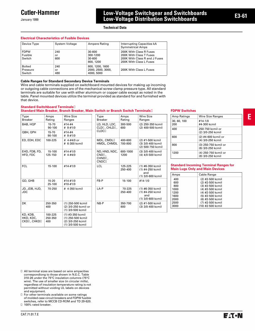
January 1999
Cutler-Hammer
CAT.71.01.T.E
E
E3-61Low-Voltage Switchgear and SwitchboardsLow-Voltage Distribution SwitchboardsTechnical Data
Standard Switchboard Terminals➀Standard Main Breaker, Branch Breaker, Main Switch or Branch Switch Terminals➁
TypeBreaker
AmpsRating
Wire SizeRanges
TypeBreaker
AmpsRating
Wire SizeRanges
BAB, HQP 15-7090-100
#14-#4# 8-#1/0
LD, HLD, LDC, CLD➂, CHLD➂, CLDC➂
300-500600
(2) 250-350 kcmil(2) 400-500 kcmil
QBH, QPH 15-7090-100
#14-#4# 8-#1/0
ED, EDH, EDC 100-225 # 4-#4/0 or# 6-300 kcmil
MDL, CMDL➂HMDL, CHMDL
400-600700-800
(2) #1-500 kcmil(3) 3/0-400 kcmil(2) 500-750 kcmil
EHD, FDB, FD,HFD, FDC
15-100125-150
#14-#1/0# 4-#4/0
ND, HND, NDC, CND➂, CHND➂, CNDC➂
600-10001200
(3) 3/0-400 kcmil(4) 4/0-500 kcmil
FCL 15-100 #14-#1/0 LCL 125-225250-400
(1) #6-350 kcmil(1) #4-250 kcmil and(1) 3/0-600 kcmil
GD, GHB 15-2025-100
#14-#1/0#10-#1/0
FB-P 15-100 #14-1/0
JD, JDB, HJD, JDC
70-250 # 4-350 kcmil LA-P 70-225250-400
(1) #6-350 kcmil(1) #4-250 kcmil and(1) 3/0-600 kcmil
DK 250-350400
(1) 250-500 kcmil(2) 3/0-250 kcmil or(1) 3/0-500 kcmil
NB-P 350-700800
(2) #1-500 kcmil(3) 3/0-400 kcmil
KD, KDB,HKD, KDC,CKD➂, CHKD➂
100-225250-350400
(1) #3-350 kcmil(1) 250-500 kcmil(2) 3/0-250 kcmil(1) 3/0-500 kcmil
FDPW Switches
Amp Ratings Wire Size Ranges
30, 60, 100200
#14-1/0#4-300 kcmil
400 250-750 kcmil or(2) 3/0-250 kcmil
600 (2) #4-600 kcmil or(4) 3/0-250 kcmil
800 (3) 250-750 kcmil or(6) 3/0-250 kcmil
1200 (4) 250-750 kcmil or(8) 3/0-250 kcmil
Cable Ranges for Standard Secondary Device TerminalsWire and cable terminals supplied on switchboard mounted devices for making up incoming or outgoing cable connections are of the mechanical screw clamp pressure type. All standard terminals are suitable for use with either aluminum or copper cable except as noted in the table. Panel mounted devices utilize the terminal provided as standard for and furnished with that device.
Electrical Characteristics of Fusible Devices
Device Type System Voltage Ampere Rating Interrupting Capacities kA Symmetrical Amps
FDPWFusibleSwitch
240or600
30-600300-120030-600800, 1200
200K With Class R Fuses200K With Class T Fuses200K With Class R and J Fuses200K With Class L Fuses
BoltedPressureSwitch
240or480
800, 1200, 16002000, 2500, 3000,4000, 5000
200K With Class L Fuses
➀ All terminal sizes are based on wire ampacities correspondiong to those shown in N.E.C. Table 310-26 under the 75°C insulation columns (75°C wire). The use of smaller size (in circular mills), regardless of insulation temperature rating is not permitted without voiding UL labels on devices and equipment.
➁ For other terminals available on some ratings of molded case circuit breakers and FDPW fusible switches, refer to MCCB CD-ROM and TD 29-620.
➂ 100% rated breaker.
Standard Incoming Terminal Ranges for Main Lugs Only and Main Devices
Amps Cable Range
400 600 800100012001600200025003000
(2) #2-500 kcmil (2) #2-500 kcmil (3) #2-500 kcmil (4) #2-500 kcmil (4) #2-500 kcmil (5) #2-500 kcmil (6) #2-500 kcmil (7) #2-500 kcmil(10) #2-500 kcmil

CAT.71.01.T.E
Cutler-HammerJanuary 1999
E
E3-62 Low-Voltage Switchgear and SwitchboardsLow-Voltage Distribution SwitchboardsTechnical Data – Clipper Power Systems
Seven Clipper Power Systems to Meet Your Needs
Model CPS-M CPS-H2 CPS-H CPS-S3 CPS-S2 CPS-S CPS-B
Application Main panels, high surge current environment Branch panels, normal surge current environment
Surge Current Ratings- Per Phase- Line to Neutral
400,000 Amps200,000 Amps
300,000 Amps150,000 Amps
250,000 Amps125,000 Amps
200,000 Amps100,000 Amps
160,000 Amps 80,000 Amps
120,000 Amps 60,000 Amps
100,000 Amps50,000 Amps
Filter Noise Attenuation 55 dB @ 100 kHz 55 dB @ 100 kHz 55 dB @ 100 kHz 55 dB @ 100 kHz 55 dB @ 100 kHz 55 dB @ 100 kHz 40 dB @ 100 kHz
Cutler-Hammer’s Integrated Design Provides Lowest System Let-Through Voltage at the Bus Bar
● The CPS stated let-through voltage is a true indication of the suppressor’s performance.
● Other TVSS products are measured at the TVSS module or the suppressor terminal, not at the bus bar. The distance between module or suppressor terminals and switchboard bus bar can be up to 14 inches or more. The impedance associated with this lead length can significantly increase the transient let-through voltage.
Standard Features
Direct bus bar couplingDiagnostics
- Tri Monitor- Status indicator lights on each phase- Trouble light
Testing procedures- Dielectric integrity- Factory power test and TVSS quality assurance
Internal fusingIntegrated TVSS/Panelboard design
Optional Features
Diagnostics- Facility monitoring system connection (IMPACC/PowerNet)- Audible alarm
Transient counter
Disconnect switch for isolating TVSS unitMost Cutler-Hammer panelboard modifications
Standard CPS Performance Specifications
1. Let-Through Voltage at the PanelboardBus Bar➀
Actual UL 1449 Test Results at the Bus Bar➁
System Configuration L-L L-N L-G N-G
208Y/120V, 120/240V, 240V ∆ 680V 431V 423V 375V
480Y/277V, 480V ∆ 1469V 842V 877V 872V
600Y/347V, 600V ∆ 1673V 1033V 1069V 1029V
2. Maximum continuous operating voltage (without affecting MOV performance or life):● 250/150V for 208Y/120V systems.● 550/320V for 480Y/277V systems.
3. TVSS response time is less than 1 nano-second (1 x 10⁻⁹ second).
4. Modes of surge suppression protection:
● Seven modes for 3-phase wye systems.
● Six modes for 3-phase delta and single-phase 3-wire systems.
5. EMI/RFI noise attenuation (MIL standard 220A) 50 ohm insertion loss test:
● 55 dB @ 100 kHz.
6. Tracking filter bandwidth of 10 kHz to 50 MHz.
7. Withstand capabilities:3000 category C surges with less than a 5% change in clamping voltage.
8. Operating frequency:45-65 Hz.
9. The TVSS filter is UL 1449 (surge suppres-sion devices) and UL 1283 (noise filtration devices) recognized. The integrated switchboard is listed under UL 891.
10.UL 1449 suppression ratings (L-N, L-G, N-G) are:400V for 208Y/120V systems.1000V for 480Y/277V systems.1200V for 600Y/347V systems.
➀ Tests were performed on a wye system.➁ Test results include impedance effects associated
with installation wiring, diagnostic monitor and in-terrupting device. Tests performed by UL using ANSI/IEEE combination (impulse) wave - 6000V, 3000A.
208Y/120V Switchboard
0 5 10
800
Time (microseconds)
Let-
Th
rou
gh
Vo
ltag
e at
Bu
s B
ar
•Based on IEEEC62.41 (1991)Combination WaveForm Category B3/C1(6000V, 3000A;8x20 ms) using #10AWG wire.
Cutler-Hammer CPS Integrated Unit
Side Mounted TVSS Devices(Assuming 14-Inch Lead Length to Bus Bar)
400
The TVSS Tri-MonitorE is the most reli-able and comprehensive diagnostic sys-tem available in the industry. This design incorporates three levels of detection:
1. Coordinated monitoring of 200 kAIC internal fuses.
2. Infrared sensor monitors individual MOVs including N-G and identifies component damage such as open MOV failure.
3. Thermal alarm detects overheating due to thermal run away.
Any problems detected by the TSS MonitorE will activate the flashing trouble light, audible alarm and Form C contacts.

January 1999
Cutler-Hammer
CAT.71.01.T.E
E
E3-63Low-Voltage Switchgear and SwitchboardsLow-Voltage Distribution SwitchboardsTypical Specifications – Front or Rear Accessible, Group Mounted Feeders Pow-R-Line C
1. RatingsA. The assembly shall be rated to withstand
mechanical forces exerted during short-circuit conditions when connected directly to a power source having avail-able fault current [of (65,000) (100,000) amperes symmetrical at rated voltage] [as shown on the drawings].
B. Voltage rating to be as indicated on the drawings.
2. ConstructionA. Switchboard shall consist of the required
number of vertical sections bolted together to form a rigid assembly. The sides and rear shall be covered with removable bolt-on covers. All edges of front covers or hinged front panels shall be formed. Provide adequate ventilation within the enclosure.
B. All sections of the switchboard shall be rear aligned with depth as shown on the drawings. All protective devices shall be group mounted. Devices shall be front removable and load connections front accessible enabling switchboard to be mounted against a wall.
– OR –
B. All sections of the switchboard shall be front and rear aligned with depth as shown on drawings. All protective devices shall be group mounted. Devices shall be front removable and load connec-tions front and rear accessible. Rear access shall be provided.
C. The assembly shall be provided with adequate lifting means.
D. The switchboard shall be equal to Cutler-Hammer type Pow-R-Line C utilizing the components herein specified and as shown on the drawings.
E. The switchboard shall be suitable for use as service entrance equipment and be labeled in accordance with UL requirements.
3. BusA. All bus bars shall be [silver-plated copper]
[tin-plated aluminum]. Main horizontal bus bars shall be mounted with all three phases arranged in the same vertical plane. Bus sizing shall be based on NEMA standard temperature rise criteria of 65 degrees C over a 40 degrees C ambient (outside the enclosure).
B. Provide a full capacity neutral bus where a neutral bus is indicated on the drawings.
C. A copper ground bus (minimum 1/4 x 2 inch), shall be furnished firmly secured to each vertical section structure and shall extend the entire length of the switchboard.
D. All hardware used on conductors shall be high-tensile strength and zinc-plated. All bus joints shall be provided with conical spring-type washers.
4. Wiring/TerminationsA. Small wiring, necessary fuse blocks and
terminal blocks within the switchboard shall be furnished as required. Control components mounted within the assem-bly, such as fuse blocks, relays, pushbut-tons, switches, etc., shall be suitably marked for identification corresponding to appropriate designations on manufac-turer's wiring diagrams.
B. Mechanical-type terminals shall be pro-vided for all line and load terminations suitable for copper or aluminum cable rated for 75 degrees C of the size as indi-cated on the drawings.
C. Lugs shall be provided in the incoming line section for connection of the main grounding conductor. Additional lugs for connection of other grounding conduc-tors shall be provided as indicated on the drawings.
D. All control wire shall be type SIS, bundled and secured with nylon ties. Insulated locking spade terminals shall be provided for all control connections, except where saddle type terminals are provided inte-gral to a device. All current transformer secondary leads shall first be connected to conveniently accessible short-circuit terminal blocks before connecting to any other device. All groups of control wires leaving the switchboard shall be provided with terminals blocks with suitable num-bering strips. Provide wire markers at each end of all control wiring.
For switchboards with only molded case breakers, go directly to “Molded Case Protective Devices”. For other types of mains and ties, see below:
Select main and tie device spec from sections below as follows:
Air Power Circuit Breakers – Section G1
Bolted Pressure Switches – Cutler-Hammer Product Specification Guide 16475
Fusible Switches – Cutler-Hammer Product Specification Guide 16475
5. Protective DevicesA. Main (and Tie) Protective Devices.
6. Molded Case Protective DevicesA. [Main] [Tie] [Feeder] protective devices
shall be molded case circuit breakers with inverse time and instantaneous tripping characteristics and shall have ground fault protection where indicated or as required by NEC. Molded case breakers shall be Cutler-Hammer type Series C or approved equal.
B. Circuit breakers shall be operated by a toggle-type handle and shall have a quick-make/quick-break over-center switching mechanism that is mechanically trip-free. Automatic tripping of the breaker shall be clearly indicated by the handle position. Contacts shall be nonwelding silver alloy, and arc extinction shall be accomplished by means of DE-ION arc chutes. A push-to-trip button on the front of the circuit breaker shall provide a local manual means to exercise the trip mechanism.
C. Circuit breakers shall have a minimum symmetrical interrupting capacity as indicated on the drawings.
D. Where indicated circuit breakers shall be UL listed for series application.
E. Where indicated circuit breakers shall be current limiting.
F. Circuit breakers [150-] [250-] [400-] [600-] ampere frame and below shall be Cutler-Hammer type Series C with thermal-mag-netic trip units and inverse time-current characteristics.
Insert trip units into paragraph G below from section G3 as follows:
For all molded case breakers:
Digitrip 310 – Basic protection
– OR –
For 400-amp and above, the following are available:
OPTIM 550 – Programmable
OPTIM 750 – Programmable with communications, current display
OPTIM 1050 – Same as OPTIM 750 plus energy, power factor, harmonic data
G. Circuit breakers [400-] [600-] ampere through 1200-ampere frame shall be Cutler-Hammer type Series C with micro-processor-based RMS sensing trip units.

CAT.71.01.T.E
Cutler-HammerJanuary 1999
E
E3-64 Low-Voltage Switchgear and SwitchboardsLow-Voltage Distribution SwitchboardsTypical Specifications – Front or Rear Accessible, Group Mounted Feeders Pow-R-Line C
For a complete product specification in CSI format, see Cutler-Hammer Product Specification Guide, section 16429.
For molded case breakers 1600 amperes through 2500 amperes:
Insert applicable trip unit spec into paragraph H below from section G3 as follows:
Digitrip RMS310 – Basic protection
Digitrip RMS510 – Same as 310 plus additional curve shaping
Digitrip RMS610 – Same as 510 plus local current display
Digitrip RMS810 – Same as 610 plus energy monitoring/display and remote communications
Digitrip RMS910 – Same as 810 plus voltage, power factor and harmonic analysis and display
Digitrip OPTIM 550 – Programmable curve shaping
Digitrip OPTIM 750 – Programmable curve shaping, load monitoring and communications
Digitrip OPTIM 1050 – Same as 750 plus power and energy monitoring, harmonic monitoring and analysis
H. Circuit breakers 1600-ampere through 2500-ampere frame shall be Cutler-Hammer type Series C with microproc-essor-based RMS sensing trip units.
I. Where indicated, provide circuit breakers UL listed for application at 100% of their continuous ampere rating in their intended enclosure.
7. AccessoriesA. Provide shunt trips, bell alarms and auxil-
iary switches as shown on the contract drawings.
For individual molded case breaker energy monitoring, add under acces-sories the IQ Energy Sentinel from section B1 in paragraph B below.
B. Circuit Breaker Energy Monitoring
Must also add centralized display under accessories type (CED) Central Energy Display from section B4 or for central-ized local monitoring of the IQ Energy Sentinel, Digitrip 810, 910 and OPTIM 750 or 1050, insert the Breaker Interface Module (BIM) unit spec from section B4 into paragraph C below.
C. Centralized Local Monitoring
D. Provide transient voltage surge suppres-sion as specified in section L.
8. Miscellaneous DevicesA. Key interlocks shall be provided as indi-
cated on the drawings.
B. Control power transformers with primary and secondary protection shall be pro-vided, as indicated on the drawings, or as required for proper operation of the equipment. [Control power transformers shall have adequate capacity to supply power to the transformer cooling fans.]
C. Each section of the switchboard shall be provided with a space heater [thermostat-ically controlled]. Power for the space heaters shall be obtained [from a control power transformer within the switch-board] [from a source as indicated on the drawings]. Supply voltage shall be [120] [240] volts AC.
9. Utility MeteringA. Where indicated on the drawings, furnish
a separate barriered-off Utility Metering Compartment complete with hinged seal-able door. Bus work shall include provi-sions for mounting utility company current transformers and potential trans-formers or potential taps as required by the utility company. Provide Service Entrance Label and provide necessary applicable service entrance features per NEC and local code requirements.
10. Customer MeteringA. Where indicated on the drawings, provide
a separate customer metering compart-ment with front hinged door and include the following:
B. Current transformers for each meter. Cur-rent transformers shall be wired to short-ing-type terminal blocks.
C. [Potential transformers including primary and secondary fuses with disconnecting means] [Fused potential taps as the potential source] for metering as shown on the drawings.
Select devices as required for item D. Refer to section B1 for detailed specification for metering.
IQ Analyzer
IQ DP 4000
IQ Generator
IQ 200
D. Microprocessor-Based Metering System
11. EnclosuresA. NEMA Type 1 Enclosure
B. Outdoor NEMA Type 3R Enclosure
1. Outdoor enclosure shall be non-walk-in and meet applicable NEMA Type 3R UL requirements.
2. Enclosure shall have [flat roof] [slop-ing roof downward toward rear].
3. Outer sections shall be the same widths as indoor structures, except each end of the outdoor assembly shall have an end trim.
4. The enclosure shall be provided with [bolt-on rear covers] [rear hinged doors] for each section.
5. Doors shall have provisions for padlocking.
6. Ventilating openings shall be pro-vided [complete with replaceable fiber glass air filters].
7. Provide space heaters [thermostati-cally controlled] for each structure with adequate wattage to prevent the accumulation of moisture.
8. Power for space heaters, lights and receptacles shall be obtained from a [control power transformer within the switchboard] [source as indicated on the drawings]. Supply voltage shall be [120] [240] volts AC.
12. NameplatesC. Engraved nameplates, mounted on the
face of the assembly, shall be furnished for all main and feeder circuits as indi-cated on the drawings. Nameplates shall be laminated plastic, black characters on white background. Characters shall be 3/16-inch high, minimum. Nameplates shall give item designation and circuit number as well as frame ampere size and appropriate trip rating. Furnish master nameplate giving switchboard desig-nation, voltage ampere rating, short-circuit rating, manufacturer‘s name, general order number, and item number.
D. Control components mounted within the assembly, such as fuse blocks, relays, pushbuttons, switches, etc., shall be suit-ably marked for identification correspond-ing to appropriate designations on manufacturer’s wiring diagrams.
13. FinishA. All exterior and interior steel surfaces of
the switchboard shall be properly cleaned and provided with a rust-inhibiting phos-phatized coating. Color and finish of the switchboard shall be ANSI 61 light gray.

January 1999
Cutler-Hammer
CAT.71.01.T.E
E
E3-65Low-Voltage Switchgear and SwitchboardsLow-Voltage Distribution SwitchboardsTypical Specifications – Rear Accessible, Compartmentalized Feeders Pow-R-Line i
1. RatingsA. The assembly shall be rated to withstand
mechanical forces exerted during short-circuit conditions when connected directly to a power source having avail-able fault current [of (65,000) (100,000) amperes symmetrical at rated voltage] [as shown on the drawings].
B. Voltage rating to be as indicated on the drawings.
2. ConstructionA. Switchboard shall consist of the required
number of vertical sections bolted together to form a rigid assembly. The sides and rear shall be covered with removable bolt-on covers. All edges of front covers or hinged front panels shall be formed. Provide adequate ventilation within the enclosure.
B. All sections of the switchboard shall align front and rear with depth as shown on the drawings. All protective devices shall be compartmentalized with line and load bus connections. Devices shall be front removable and load connections rear accessible. Insulated rigid copper bus connections shall extend from the load side of overcurrent feeder devices into rear compartment where outgoing cable connections may be made without reach-ing into or near the main horizontal or vertical busses. Distribution sections shall be sectionalized to provide a front device section, an intermediate bus section and a rear feeder cable section. There shall be a vertical barrier of glass polyester between the device compartment and the bus compartment.
C. The assembly shall be provided with adequate lifting means.
D. Provide a rear compartment vertical insu-lating barrier between the cable compart-ment and the main bus to protect against inadvertent contact with main or vertical bus bars.
E. The switchboard shall be equal to Cutler-Hammer type Pow-R-Line i utilizing the components herein specified and as shown on the drawings.
F. The switchboard shall be suitable for use as service entrance equipment and be labeled in accordance with UL requirements.
3. BusA. All bus bars shall be [silver-plated copper]
[tin-plated aluminum]. Main horizontal bus bars shall be mounted with all three phases arranged in the same vertical plane. Bus sizing shall be based on NEMA standard temperature rise criteria of 65 degrees C over a 40 degrees C ambient (outside the enclosure).
B. Provide a full capacity neutral bus where a neutral bus is indicated on the drawings.
C. A copper ground bus (minimum 1/4 x 2 inch) shall be furnished firmly secured to each vertical section structure and shall extend the entire length of the switchboard.
D. All hardware used on conductors shall be high-tensile strength and zinc-plated. All bus joints shall be provided with conical spring-type washers.
4. Wiring/TerminationsA. Small wiring, necessary fuse blocks and
terminal blocks within the switchboard shall be furnished as required. Control components mounted within the assem-bly, such as fuse blocks, relays, pushbut-tons, switches, etc., shall be suitably marked for identification corresponding to appropriate designations on manufac-turer’s wiring diagrams.
B. [Mechanical-] [Crimp-] type terminals shall be provided for all line and load ter-minations suitable for copper or alumi-num cable rated for 75 degrees C of the size as indicated on the drawings.
C. Lugs shall be provided in the incoming line section for connection of the main grounding conductor. Additional lugs for connection of other grounding conduc-tors shall be provided as indicated on the drawings.
D. All control wire shall be type SIS, bundled and secured with nylon ties. Insulated locking spade terminals shall be provided for all control connections, except where saddle-type terminals provided are inte-gral to a device. All current transformer secondary leads shall first be connected to conveniently accessible short-circuit terminal blocks before connecting to any other device. All groups of control wires leaving the switchboard shall be provided with terminal blocks with suitable num-bering strips. Provide wire markers at each end of all control wiring.
For switchboards with only molded case breakers, go directly to “Molded Case Protective Devices.” For other types of mains and ties, see below:
Select main and tie device spec from sections below:
Air Power Circuit Breakers – section G1
Bolted Pressure Switches – Cutler-Hammer Product Specification Guide 16475
Fusible Switches – Cutler-Hammer Product Specification Guide 16475
5. Protective DevicesA. Main (and Tie) Protective Devices
6. Molded Case Protective DevicesA. [Main] [Tie] [Feeder] protective devices
shall be molded case circuit breakers with inverse time and instantaneous tripping characteristics and shall have ground fault protection where indicated or as required by NEC. Molded case breakers shall be Cutler-Hammer type Series C or approved equal.
B. Circuit breakers shall be operated by a toggle-type handle and shall have a quick-make, quick-break over-center switching mechanism that is mechanically trip-free. Automatic tripping of the breaker shall be clearly indicated by the handle position. Contacts shall be nonwelding silver alloy, and arc extinction shall be accomplished by means of DE-ION arc chutes. A push-to-trip button on the front of the circuit breaker shall provide a local manual means to exercise the trip mechanism.
C. Circuit breakers shall have a minimum symmetrical interrupting capacity as indi-cated on the drawings.
D. Where indicated, circuit breakers shall be UL listed for series application.
E. Where indicated, circuit breakers shall be current limiting.
F. Circuit breakers [150-] [250-] [400-] [600-] ampere frame and below shall be Cutler-Hammer type Series C with thermal-mag-netic trip units and inverse time-current characteristics.
Insert trip units into paragraph G below from section G3 as follows:
For all molded case breakers:
Digitrip 310 – Basic protection
– OR –
For 400 amperes and above, the following are available:
OPTIM 550 – Programmable
OPTIM 750 – Programmable with communications, current display
OPTIM 1050 – Same as Optim 750 plus energy, power factor, harmonic data
G. Circuit breakers [400-] [600-] ampere through 1200-ampere frame shall be Cutler-Hammer type Series C with micro-processor-based RMS sensing trip units.
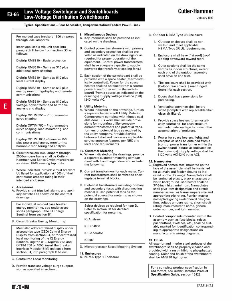
CAT.71.01.T.E
Cutler-HammerJanuary 1999
E
E3-66 Low-Voltage Switchgear and SwitchboardsLow-Voltage Distribution SwitchboardsTypical Specifications – Rear Accessible, Compartmentalized Feeders Pow-R-Line i
For molded case breakers 1600 amperes through 2500 amperes:
Insert applicable trip unit spec into paragraph H below from section G3 as follows:
Digitrip RMS310 – Basic protection
Digitrip RMS510 – Same as 310 plus additional curve shaping
Digitrip RMS610 – Same as 510 plus local current display
Digitrip RMS810 – Same as 610 plus energy monitoring/display and remote communications
Digitrip RMS910 – Same as 810 plus voltage, power factor and harmonic analysis and display
DIgitrip OPTIM 550 – Programmable curve shaping
Digitrip OPTIM 750 – Programmable curve shaping, load monitoring, and communications
Digitrip OPTIM 1050 – Same as 750 plus power and energy monitoring; harmonic monitoring and analysis
H. Circuit breakers 1600-ampere through 2500-ampere frame shall be Cutler-Hammer type Series C with microproces-sor-based RMS sensing trip units.
I. Where indicated, provide circuit breakers UL listed for application at 100% of their continuous ampere rating in their intended enclosure.
7. AccessoriesA. Provide shunt trips bell alarms and auxil-
iary switches as shown on the contract drawings.
For individual molded case breaker energy monitoring, add under acces-sories paragraph B the IQ Energy Sentinel from section B1.
B. Circuit Breaker Energy Monitoring
Must also add centralized display under accessories type (CED) Central Energy Display from section B4, or for centralized local monitoring of the IQ Energy Sentinel, Digitrip 810, Digitrip 910, and OPTIM 750 or 1050, insert the Breaker Interface Module (BIM) unit spec from section B4, into paragraph C below.
C. Centralized Local Monitoring
D. Provide transient voltage surge suppres-sion as specified in section L.
8. Miscellaneous DevicesA. Key interlocks shall be provided as indi-
cated on the drawings.
B. Control power transformers with primary and secondary protection shall be pro-vided as indicated on the drawings or as required for proper operation of the equipment. [Control power transformers shall have adequate capacity to supply power to the transformer cooling fans.]
C. Each section of the switchboard shall be provided with a space heater [thermostat-ically controlled]. Power for the space heaters shall be obtained [from a control power transformer within the switch-board] [from a source as indicated on the drawings]. Supply voltage shall be [120] [240] volts AC.
9. Utility MeteringA. Where indicated on the drawings, furnish
a separate barriered-off Utility Metering Compartment complete with hinged seal-able door. Bus work shall include provi-sions for mounting utility company current transformers and potential trans-formers or potential taps as required by the utility company. Provide Service Entrance Label and necessary applicable service entrance features per NEC and local code requirements.
10. Customer MeteringA. Where indicated on the drawings, provide
a separate customer metering compart-ment with front hinged door and include the following:
B. Current transformers for each meter. Cur-rent transformers shall be wired to short-ing-type terminal blocks.
C. [Potential transformers including primary and secondary fuses with disconnecting means] [Fused potential taps as the potential source] for metering as shown on the drawings.
Select devices as required for item D. Refer to section B1 for detailed specification for metering.
IQ Analyzer
IQ DP 4000
IQ Generator
IQ 200
D. Microprocessor-Based Metering System
11. EnclosuresA. NEMA Type 1 Enclosure
B. Outdoor NEMA Type 3R Enclosure
1. Outdoor enclosure shall be non-walk-in and meet applicable NEMA Type 3R UL requirements.
2. Enclosure shall have [flat roof] [roof sloping downward toward rear].
3. Outer sections shall be the same widths as indoor structures, except each end of the outdoor assembly shall have an end trim.
4. The enclosure shall be provided with [bolt-on rear covers] [ rear hinged doors] for each section.
5. Doors shall have provisions for padlocking.
6. Ventilating openings shall be pro-vided [complete with replaceable fiber glass air filters].
7. Provide space heaters [thermostati-cally controlled] for each structure with adequate wattage to prevent the accumulation of moisture.
8. Power for space heaters, lights and receptacles shall be obtained from a [control power transformer within the switchboard] [source as indicated on the drawings]. Supply voltage shall be [120 volts AC] [240 volts AC].
12. NameplatesC. Engraved nameplates, mounted on the
face of the assembly, shall be furnished for all main and feeder circuits as indi-cated on the drawings. Nameplates shall be laminated plastic, black characters on white background. Characters shall be 3/16-inch high, minimum. Nameplates shall give item designation and circuit number as well as frame ampere size and appropriate trip rating. Furnish master nameplate giving switchboard designa-tion, voltage ampere rating, short-circuit rating, manufacturer‘s name, general order number, and item number.
D. Control components mounted within the assembly such as fuse blocks, relays, pushbuttons, switches, etc., shall be suit-ably marked for identification correspond-ing to appropriate designations on manufacturer’s wiring diagrams.
13. FinishAll exterior and interior steel surfaces of the switchboard shall be properly cleaned and provided with a rust-inhibiting phosphatized coating. Color and finish of the switchboard shall be ANSI 61 light gray.
For a complete product specification in CSI format, see Cutler-Hammer Product Specification Guide, section 16428.

January 1999
Cutler-Hammer
CAT.71.01.T.E
E
E3-67Low-Voltage Switchgear and SwitchboardsLow-Voltage Distribution SwitchboardsTypical Specifications – TVSS Pow-R-Line C and Pow-R-Line i Switchboard
Refer to Group Mounted Feeder Devices Specification page E3-64 or Compartmented Feeder Specification page E3-65 for General Switchboard Construction Specifications.
Transient Voltage Surge Suppression – GeneralA. Transient Voltage Surge Suppression
(TVSS) equipment shall be Cutler-Hammer type Clipper Power Systems (CPS) or approved equal meeting all ratings and features specified herein.
B. Electrical requirements
1. Unit Operating Voltage – Refer to drawings for operating voltage and unit configuration.
2. Maximum Continuous Operating Voltage (MCOV) – The MCOV shall be greater than 115% of the nominal system operating voltage.
3. Protection Modes – For a wye config-ured system, the device must have directly connected suppression elements between line-neutral (L-N), line-ground (L-G), and neutral-ground (N-G). For a delta configured system, the device must have suppression elements between line-to-line (L-L) and line-to-ground (L-G).
4. UL 1449 SVR – The maximum UL 1449 SVR for the device must not exceed the following:
5. ANSI/IEEE Cat C3 Let-Through Voltage – The let-through voltage based on IEEE C62.41 and C62.45 recommended procedures for Category C3 surges (20 kV, 10 kA) shall be less than:
6. ANSI/IEEE Cat. B3 Let-Through Volt-age – Let-through voltage based on IEEE C62.41 and C62.45 recommended procedures for the ANSI/IEEE Cat. B3 ringwave (6 kV, 5000 amperes) shall be less than:
C. TVSS Design
1. Balanced Suppression Platform – The surge current shall be equally distrib-uted to all MOV components to ensure equal stressing and maximum perfor-mance. The surge suppression plat-form must provide equal impedance
Models 208Y/120 480Y/277 600Y/347
L-N; L-G; N-G 400 V 800 V 1200 V
L-L 800 V 1500 V 2000 V
Models 208Y/120 480Y/277 600Y/347
L-N 470 V 900 V 1300 V
Models 208Y/120 480Y/277 600Y/347
L-N 150 V 200 V 300 V
paths to each matched MOV. Designs incorporating TVSS modules which do not provide a balanced impedance path to each MOV shall not be acceptable.
2. Electrical Noise Filter – Each unit shall include a high-performance EMI/RFI noise rejection filter. Noise attenuation for electric line noise shall be 55 dB at 100 kHz using the MIL-STD-220A insertion loss test method. The unit shall be complementary listed to UL 1283. Products not able to demon-strate noise attenuation of 55 dB @ 100 kHz shall be rejected.
3. Internal Connections – No plug-in component modules or printed circuit boards shall be used as surge current conductors. All internal components shall be hardwired with connections utilizing low impedance conductors and compression fittings.
4. Safety and Diagnostic Monitoring – Each unit shall be equipped with 200 kAIC internal fuses. Each unit shall provide the following three levels of monitoring:
a. Continuous monitoring of fusing system.
b. Internal infrared sensor system for monitoring individual MOVs (including neutral to ground). The system must be capable of identi-fying open circuit failures not mon-itored by conventional fusing systems.
c. Thermal detection circuit shall monitor for overheating in all modes due to thermal runaway.
A green/red solid state indicator light shall be provided on each phase. The absence of a green light and the presence of a red light, shall indicate which phase(s) have been damaged. Fault detec-tion will activate a flashing trouble light. Units which can not detect open-circuit damage, thermal con-ditions and over current will not be accepted.
5. Warranty – The manufacturer shall provide a full five (5-) year warranty from the date of shipment against any TVSS part failure when installed in compliance with manufacturer’s writ-ten instructions and any applicable national or local electric code.
6. TVSS devices shall be mounted such that they are seismically qualified for UBC and California Building Code Zone 4 applications.
7. The unit must be equipped with tran-sient event counter and audible alarm.
8. Remote Status Monitor – The TVSS device must include form C dry con-tacts (one NO and one NC) for remote annunciation of unit status. The remote alarm shall change state if any of the three monitoring systems described detect a fault condition.
9. Push-To-Test Feature – Each suppres-sion unit shall incorporate an integral test feature which verifies the opera-tional integrity of the unit's monitor-ing system.
System ApplicationD. The TVSS applications covered under this
section include switchboard assemblies.
Surge Current Capacity – The minimum total surge current 8 x 20 microsecond waveform that the device is capable of withstanding shall be as shown in the following table:
Optional ratings are available for insertion in above table based on project requirement [400] kA per phase, or [200] kA per mode on L-G, L-N and N-G modes (Wye system); L-L and N-G (delta system).
E. Switchboard Requirements
1. The TVSS application covered under this section is for switchboard loca-tions. The service entrance TVSS shall be tested and suitable for ANSI/IEEE C62.41 Category C3 environments.
2. Service entrance suppressor shall be installed by assembly manufacturer.
3. Withstand. Each unit must be capable of surviving more than 2500 ANSI/IEEE C62.41 Category C1 transients without failure or degradation of UL 1449 Suppression Voltage Rating.
4. Service entrance suppressors shall be installed in the assembly.
Application Min. Surge CurrentPer Phase
Min. SurgeCurrentPer Mode➀
Service Entrance Switchboards
250 kA 125 kA
Distribution Switchboards
160 kA 80 kA
➀ L-G, L-N and N-G (WYE system); L-L, L-G (Delta system)
CAT.71.01.T.E
Cutler-HammerJanuary 1999
E
E3-68 Low-Voltage Switchgear and SwitchboardsLow-Voltage Distribution SwitchboardsTypical Specifications – TVSS Pow-R-Line C and Pow-R-Line i Switchboards
5. Locate suppressor on load side of main disconnect device, as close as possible to the phase conductors and ground/neutral bar.
6. Provide a 30-amperes disconnect. The disconnect shall be directly integrated to the suppressor and assembly bus using bolted bus bar connections.
7. The suppressor and integral discon-nect shall be installed to the switch-board using a direct bus bar connection (no cable connection between bus bar and TVSS device). TVSS units that use a wire connection do not meet the intent of this specification.
8. All monitoring diagnostics features such as indicator lights, trouble alarms and surge counter (if specified) shall be mounted on the front of the switchboard.
AccessoriesA. Push to test feature to verify operational
integrity.
B. Form C dry contacts one NO, one NC for remote status monitoring.
C. Provide audible alarm and surge counter as shown on the contract drawings.
For a complete product specification in CSI format, see Cutler-Hammer Product Specification Guide, section 16671.