who stole my high performance building - minnesota ashrae
TRANSCRIPT

WHO STOLE MY HIGHWHO STOLE MY HIGH--PERFORMANCE PERFORMANCE
BUILDING? BUILDING? –– Part 1Part 1For
2012 Region VI
Chapter Regional ConferenceByBy
Todd Rindlisbaker, PE, QCxP,
LEED AP, HPBDP, CPD .
Rindlisbaker Commissioning, Inc.

1
5/8/2012 2
Todd Rindlisbaker, P.E., LEEDTodd Rindlisbaker, P.E., LEEDTMTM AP, HPBDP, AP, HPBDP, QCxPQCxP, CPD, CPD
� 19 years in mechanical HVAC engineering and commissioning
– Large hydronic systems, central plants, campus proj ects.– Control Systems and control sequences.– Energy Analysis reports and modeling
� P.E.-Licensed Professional Mechanical Engineer� LEED™- Accredited Professional� HPBDP-ASHRAE certified High Performance
Building Design Professional� QCxP-Qualified Commissioning Process Provider� National Speakers Association Apprentice� Integrated Project Delivery Process Facilitator
Who Sabotaged My HighWho Sabotaged My High--Performance Building?Performance Building?
ASHRAE WASHRAE WILLILL GGIVEIVE
YYOUOU THETHE WWORLDORLD
This ASHRAE Distinguished Lecturer is
brought to you by the Society Chapter
Technology Transfer Committee
Complete the Distinguished Lecturer Complete the Distinguished Lecturer Event Summary CritiqueEvent Summary Critique
�� CTTC needs your feedback to continue to CTTC needs your feedback to continue to improve the DL Programimprove the DL Program�Distribute the DL Evaluation Form to all
attendees�Collect at the end of the meeting�Compile the attendee rating on the Event
Summary Critique�Send the completed Event Summary Critique
to your CTTC RVC and ASHRAE Headquarters
Forms are available at:Forms are available at:www.ashrae.org/distinguishedlecturers
BBECOMEECOME A FA FUTUREUTURE LLEADEREADER ININ ASHRAE ASHRAE –– WWRITERITE THETHE NNEXTEXTCCHAPTERHAPTER IINN YYOUROUR CCAREERAREER
YOU ARE NEEDED FOR:� Membership Promotion� Research Promotion� Student Activities� Chapter Technology
Transfer Technical Committees
Find your Place in ASHRAE! Visit Find your Place in ASHRAE! Visit www.ashrae.org
ASHRAE Members who attend their monthly chapter meetings become leaders and bring information and technology back to their job.
5/8/2012 6
ObjectivesObjectives
� Identify common reasons building fail to operate properly and efficiently
� Identify “Key” Design items that will;– Save 20-30% energy (above HE equip).– Or waste up to 50% if they are missed.
� Find control strategies that provide additional energy savings.
Who Sabotaged My HighWho Sabotaged My High--Performance Building?Performance Building?
5/8/2012 7
Objectives (continued)Objectives (continued)
� Identify key coordination items that result in costly change orders.
� Strategies to communicate and specify tools used to verify functionality and energy performance.
� Two Items to include to make you a hero with the building operating staff.
Who Sabotaged My HighWho Sabotaged My High--Performance Building?Performance Building?

2
5/8/2012 8
Who Sabotaged My HighWho Sabotaged My High--Performance Building?Performance Building?
5/8/2012 9
Who Sabotaged My HighWho Sabotaged My High--Performance Building?Performance Building?
($1.25/CFM)7
Envelope Leakage Costs Envelope Leakage Costs –– Case StudyCase Study
� Building Area: 210,000 sq. ft.� Four Stories� Originally installed regular dampers in
exhaust and relief openings� Test 1 Building Leakage – 58,500 CFM� Envelope Leakage Costs - $1.25/CFM� Cost of Energy Waste: $56,700/Year5/8/2012 10
Who Sabotaged My HighWho Sabotaged My High--Performance Building?Performance Building?
Envelope Leakage Costs Envelope Leakage Costs –– Case StudyCase Study
5/8/2012 11
Who Sabotaged My HighWho Sabotaged My High--Performance Building?Performance Building?
Envelope Leakage Costs Envelope Leakage Costs –– Cx ResultsCx Results
5/8/2012 12
Who Sabotaged My HighWho Sabotaged My High--Performance Building?Performance Building?
HVAC System Envelope LeakageHVAC System Envelope Leakage
� ASHRAE 90.1
5/8/2012 13
Who Sabotaged My HighWho Sabotaged My High--Performance Building?Performance Building?

3
Summary Envelope Leakage Summary Envelope Leakage –– HVACHVAC
Recommendations: � Use Motorized, Low-Leakage type dampers for
all Outside Air, Exhaust, and Relief Air Dampers:– ROI ≈ 0.3 Years– All dampers > 300 CFM in buildings >2 stories
required to be motorized anyway.*– Coordinate with electrical & detail.
� Discourage return air plenum returns (increase building leakage, since return air plenums are always negative, grow mold in moist areas)
� Encourage Building Envelope Commissioning
5/8/2012 14
Who Sabotaged My HighWho Sabotaged My High--Performance Building?Performance Building?
Proper Building Proper Building Pressurization Measurement Pressurization Measurement
5/8/2012 15Recommended method for measuring building static pressure with BMS from ASTM E779-03
Who Sabotaged My HighWho Sabotaged My High--Performance Building?Performance Building?
Proper Building Proper Building Pressurization Measurement Pressurization Measurement
5/8/2012 16Recommended method for measuring building static pressure with BMS from ASTM E779-03
Who Sabotaged My HighWho Sabotaged My High--Performance Building?Performance Building?
Energy Usage Energy Usage –– UnderstandingUnderstandingWhere it goesWhere it goes
5/8/2012 17Energy Consumption Characteristics of Commercial Building HVAC Systems Volume II: Page 5-25
Who Sabotaged My HighWho Sabotaged My High--Performance Building?Performance Building?
Design LoadDesign Load Operating LoadOperating Load
5/8/2012 18De Bullet - Chiller Plant Fundamentals and Optimization
Annual Energy Usage Annual Operating Usage
Who Sabotaged My HighWho Sabotaged My High--Performance Building?Performance Building?
Cooling System Energy UsageCooling System Energy Usage
5/8/2012 19Energy Consumption Characteristics of Commercial Building HVAC Systems Volume II: Page 5-25
Who Sabotaged My HighWho Sabotaged My High--Performance Building?Performance Building?

4
5/8/2012 20
>50%
Who Sabotaged My HighWho Sabotaged My High--Performance Building?Performance Building?
Commercial HVAC Commercial HVAC Parasitic Energy UseParasitic Energy Use
5/8/2012 21Energy Consumption Characteristics of Commercial Building HVAC Systems Volume II: Page 1-2
Who Sabotaged My HighWho Sabotaged My High--Performance Building?Performance Building?
Fan Energy: First Step, Run only as neededFan Energy: First Step, Run only as needed� Many exhaust fans are constant speed.
– Review schedule and required use. – Operate only when needed. Many fans run
unnecessarily.– Consider Occupancy sensors where appropriate
- (with run-on delays)� HVAC Systems:
– Separate 24/7 and equipment loads from comfort cooling loads:
• Provide standalone units for areas such as data roo ms, equipment rooms, etc.
• Where not separated size for max temp. reset StPt.– Shut off air handlers at night.
5/8/2012 22
Who Sabotaged My HighWho Sabotaged My High--Performance Building?Performance Building?
Fan Energy UsageFan Energy Usage
5/8/2012 23
Who Sabotaged My HighWho Sabotaged My High--Performance Building?Performance Building?
Fan Energy Fan Energy –– Fan CurveFan Curve
5/8/2012 24
SYSTEM EFFECTS?
Who Sabotaged My HighWho Sabotaged My High--Performance Building?Performance Building?
Fan Energy Fan Energy –– System EffectsSystem Effects
5/8/2012 25
Who Sabotaged My HighWho Sabotaged My High--Performance Building?Performance Building?

5
Fan Energy – System Effects
5/8/2012 26ASHRAE Fundamentals Chapter 35 – Duct Fitting Coefficients
Who Sabotaged My HighWho Sabotaged My High--Performance Building?Performance Building?
5/8/2012 27
Fan Energy – System Effects
ASHRAE Fundamentals Chapter 35 – Duct Fitting Coefficients
Who Sabotaged My HighWho Sabotaged My High--Performance Building?Performance Building?
5/8/2012 28
Fan Energy Fan Energy –– System EffectsSystem Effects
ASHRAE Fundamentals Chapter 35 – Duct Fitting Coefficients
Who Sabotaged My HighWho Sabotaged My High--Performance Building?Performance Building?
Fan Energy Fan Energy ––System Effects ExampleSystem Effects Example
� Results:� ∆P – 2.4
in. wg
5/8/2012 29
Who Sabotaged My HighWho Sabotaged My High--Performance Building?Performance Building?
Fan Energy Fan Energy ––Air Handler ConnectionsAir Handler Connections
� Entrances & Exits - Specify
5/8/2012 30ASHRAE Fundamentals Chapter 35 – Duct Fitting Coefficients
Who Sabotaged My HighWho Sabotaged My High--Performance Building?Performance Building?
r = 0.1 (in)r= 0.16 (in) r= 0.2 (in) D (in)
2 3.2 4 20
2.5 4 5 25
3 4.8 6 30
3.5 5.6 7 35
4 6.4 8 40
5 8 10 50
Building Energy Usage Building Energy Usage –– Fan SelectionFan Selection
� Air foil fans, slightly oversized offer up to 20% higher efficiencies (Energy Consumption Characteristics of Commercial HVAC Systems Vol. III pgs A-8 to A-11)
5/8/2012 31
Who Sabotaged My HighWho Sabotaged My High--Performance Building?Performance Building?

6
Fan Energy Fan Energy –– Fan Wheel SelectionFan Wheel Selection
5/8/2012 32(Energy Consumption Characteristics of Commercial HVAC Systems Vol. III pgs A-8 to A-11)
Who Sabotaged My HighWho Sabotaged My High--Performance Building?Performance Building?
Fan Energy Fan Energy –– Fan Wheel SelectionFan Wheel Selection
5/8/2012 33(Energy Consumption Characteristics of Commercial HVAC Systems Vol. III pgs A-8 to A-11)
Who Sabotaged My HighWho Sabotaged My High--Performance Building?Performance Building?
Fan Energy Fan Energy –– Fan Wheel SelectionFan Wheel Selection
� Benefits of One to Two Sizes Larger Fan Wheel:– Up to 20% more efficient– Lower Sound Levels– Longer Bearing Life, Less Maintenance
� Caution:– Make sure system curve is still good
match to the fan curve (stay away from the surge line)
5/8/2012 34
Who Sabotaged My HighWho Sabotaged My High--Performance Building?Performance Building?
Fan Energy Fan Energy ––Air Handler SizingAir Handler Sizing
� Parameters:– Optimized for First Costs, 5 Yr & 10Yr ROI– Operating Hours 3160 and 8760– Single Zone Constant Volume, 30,000 CFM Draw-
through unit.
� Results:– 5 Yr ROI ≈ 415 FPM AHU, 600 FPM OA Louver– 10 Yr ROI ≈ 315 FPM AHU, 600 FPM OA Louver
5/8/2012 35
� ASHRAE Journal – February 2009Air Handler Design for Energy Conservation – Arthur B Wheeler
Who Sabotaged My HighWho Sabotaged My High--Performance Building?Performance Building?
Fan Energy Fan Energy ––Air Handler SizingAir Handler Sizing
5/8/2012 36
314
416
Who Sabotaged My HighWho Sabotaged My High--Performance Building?Performance Building?
Fan Energy Fan Energy –– Air Handler SizingAir Handler Sizing
Comments regarding slides 35 & 36.� This study was for a constant volume
system.� Study shows that the filters and coil
selections are two of the most critical components regarding energy savings.
� Variable volume air handlers would benefit by selecting low pressure drop filters and coils. Suggested ranges are:– Filters: 0.3 in.wg (new)– HW coil < 0.2 in.wg– CHW coil < 0.4 in.wg
5/8/2012 37
Who Sabotaged My HighWho Sabotaged My High--Performance Building?Performance Building?

7
Fan Energy Fan Energy ––Variable Volume ControlVariable Volume Control
5/8/2012 38
Who Sabotaged My HighWho Sabotaged My High--Performance Building?Performance Building?
5/8/2012 39
Fan Energy Fan Energy ––Static Pressure Set PointStatic Pressure Set Point
Who Sabotaged My HighWho Sabotaged My High--Performance Building?Performance Building?
Fan Energy Fan Energy ––Variable Volume ControlVariable Volume Control
5/8/2012 40
Who Sabotaged My HighWho Sabotaged My High--Performance Building?Performance Building?
Fan Energy Fan Energy –– Variable Volume ControlVariable Volume Control
5/8/2012 41
Who Sabotaged My HighWho Sabotaged My High--Performance Building?Performance Building?
Fan Energy Fan Energy –– Static Pressure ResetStatic Pressure Reset
� Since ASHRAE 90.1-1999
5/8/2012 42
Who Sabotaged My HighWho Sabotaged My High--Performance Building?Performance Building?
5/8/2012 43
Fan Energy Fan Energy –– Static Pressure ResetStatic Pressure Reset
ASHRAE 90.1 User’s Manual
Who Sabotaged My HighWho Sabotaged My High--Performance Building?Performance Building?

8
Fan Energy Fan Energy –– Static Pressure ResetStatic Pressure Reset
� Rules for Static Pressure Sensor Locations:– Static DP Sensor MUST be “Home Run”
to communicate directly to the air handler DDC controller. (Communication speed, reliability)
– If located downstream of major duct branches, each major branch must have sensor.
5/8/2012 44
Who Sabotaged My HighWho Sabotaged My High--Performance Building?Performance Building?
Fan Energy Fan Energy ––Static Pressure Sensor LocationStatic Pressure Sensor Location
5/8/2012 45
Who Sabotaged My HighWho Sabotaged My High--Performance Building?Performance Building?
Notes for Slide 45Notes for Slide 45
� Benefits of Static Pressure sensor at air handler d ischarge.– More reliable.– Sensor acts as an operational high static limit. (If a remote sensor cannot
meet static requirements, it increases fan speed wi thout knowing fan discharge pressure, some systems this is over the duct pressure rating, trips high limit).
– Less costly to install than remote sensor. Differe nce in cost can pay for additional sensors for informational purposes.
� Return fan control should be return plenum static p ressure (Static Pressure must be positive on building side of louve r to push relief air out).
� Outside air flow station is only reliable method of controlling outside air quantity.
� Provide system diagram and graphic requirements to contractor in design documents. Include operational and troub leshooting information.
� VAV airflows can be used to indicate supply fan air quantity within at least 5 – 10% accuracy. (Inexpensive way to provide information).
5/8/2012 46
Who Sabotaged My HighWho Sabotaged My High--Performance Building?Performance Building?
Fan Energy Fan Energy ––Return/Relief Fan LocationReturn/Relief Fan Location
5/8/2012 47
Who Sabotaged My HighWho Sabotaged My High--Performance Building?Performance Building?
Notes for Slide 47Notes for Slide 47
� Engineer’s building pressure relief sequence called for the relief air dampers to modulate open first and then to star t the relief fans and modulate them up to speed.
– Because the return air plenum is negative, outside air flowed backwards through the relief air louvers into the return air plenum. The relief air fans eventually turned on and ramped up to control the b uilding static, but there were long periods of time that the building static was out of control.
� Solution 1:– Add a static pressure sensor to the plenum between the relief fan and the
outside air louver.– Change sequence to turn on relief air fans maintain a plenum static
pressure set point.– Modulate the relief air dampers to maintain buildin g static pressure.
� Solution 2:– Change system configuration to have a return/relief fan as shown in slide
#44.– Benefits are: Smaller supply air fan requirements, more return air draw
from higher return air static pressure, and better building static pressure control.
5/8/2012 48
Who Sabotaged My HighWho Sabotaged My High--Performance Building?Performance Building?
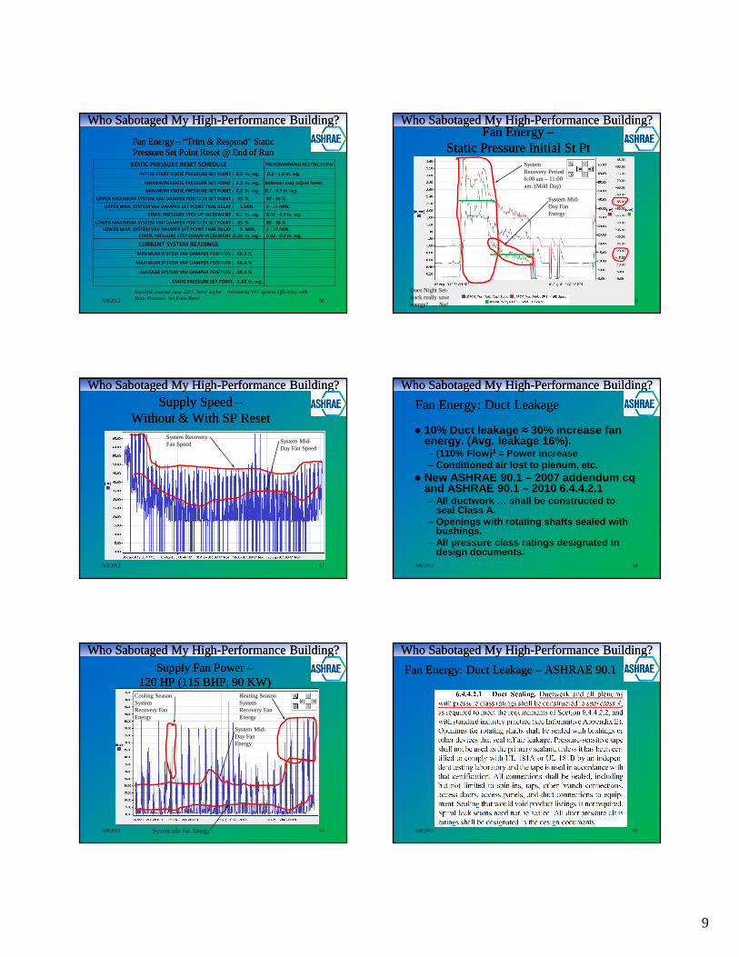
Fan Energy Fan Energy –– “Trim & Respond” Static “Trim & Respond” Static Pressure Set Point Reset @ Air HandlerPressure Set Point Reset @ Air Handler
5/8/2012 49
STATIC PRESSURE RESET SCHEDULE PROGRAMMING RESTRICTIONS
INITIAL START STATIC PRESSURE SET POINT . 0.5 in. wg. 0.2 - 1.0 in. wg.
MAXIMUM STATIC PRESSURE SET POINT . 2.5 in. wg.AS NOTED OR 0.5 LESS THAN
HIGH DUCT STATIC LIMIT
MINIMUM STATIC PRESSURE SET POINT . 0.2 in. wg. 0.1 - 0.5 in. wg.
UPPER MAXIMUM SYSTEM VAV DAMPER POSITION SET POINT . 95 % 90 - 98 %
UPPER MAX. SYSTEM VAV DAMPER SET POINT TIME DELAY . 5 MIN. 1 - 10 MIN.
STATIC PRESSURE STEP UP INCREMENT . 0.1 in. wg. 0.02 - 0.2 in. wg.
LOWER MAXIMUM SYSTEM VAV DAMPER POSITION SET POINT . 85 % 80 - 88 %
LOWER MAX. SYSTEM VAV DAMPER SET POINT TIME DELAY . 5 MIN. 1 - 10 MIN.
STATIC PRESSURE STEP DOWN INCREMENT .0.05 in. wg. 0.02 - 0.2 in. wg.
CURRENT SYSTEM READINGS
MINIMUM SYSTEM VAV DAMPER POSITION . XX.X %
MAXIMUM SYSTEM VAV DAMPER POSITION . XX.X %
AVERAGE SYSTEM VAV DAMPER POSITION . XX.X %
STATIC PRESSURE SET POINT. X.XX in. wg.
ASHRAE Journal June 2007, Steve Taylor – Increasing VAV System Efficiency with Static Pressure Set Point Reset
Who Sabotaged My HighWho Sabotaged My High--Performance Building?Performance Building?
9
Fan Energy Fan Energy –– “Trim & Respond” Static “Trim & Respond” Static Pressure Set Point Reset @ End of RunPressure Set Point Reset @ End of Run
5/8/2012 50
STATIC PRESSURE RESET SCHEDULE PROGRAMMING RESTRICTIONS
INITIAL START STATIC PRESSURE SET POINT . 0.5 in. wg. 0.2 - 1.0 in. wg.
MAXIMUM STATIC PRESSURE SET POINT . 1.2 in. wg.. Balancer may adjust lower.
MINIMUM STATIC PRESSURE SET POINT . 0.2 in. wg. 0.1 - 0.5 in. wg.
UPPER MAXIMUM SYSTEM VAV DAMPER POSITION SET POINT . 95 % 90 - 98 %
UPPER MAX. SYSTEM VAV DAMPER SET POINT TIME DELAY . 5 MIN. 1 - 10 MIN.
STATIC PRESSURE STEP UP INCREMENT . 0.1 in. wg. 0.02 - 0.2 in. wg.
LOWER MAXIMUM SYSTEM VAV DAMPER POSITION SET POINT . 85 % 80 - 88 %
LOWER MAX. SYSTEM VAV DAMPER SET POINT TIME DELAY . 5 MIN. 1 - 10 MIN.
STATIC PRESSURE STEP DOWN INCREMENT .0.05 in. wg. 0.02 - 0.2 in. wg.
CURRENT SYSTEM READINGS
MINIMUM SYSTEM VAV DAMPER POSITION . XX.X %
MAXIMUM SYSTEM VAV DAMPER POSITION . XX.X %
AVERAGE SYSTEM VAV DAMPER POSITION . XX.X %
STATIC PRESSURE SET POINT. X.XX in. wg.
ASHRAE Journal June 2007, Steve Taylor – Increasing VAV System Efficiency with Static Pressure Set Point Reset
Who Sabotaged My HighWho Sabotaged My High--Performance Building?Performance Building?
Supply Speed Supply Speed ––Without & With SP ResetWithout & With SP Reset
5/8/2012 51
System Recovery Fan Speed System Mid-
Day Fan Speed
Who Sabotaged My HighWho Sabotaged My High--Performance Building?Performance Building?
Supply Fan Power Supply Fan Power ––120 HP (115 BHP, 90 KW)120 HP (115 BHP, 90 KW)
5/8/2012 52
Heating Season System Recovery Fan Energy
System Mid-Day Fan Energy
System Idle Fan Energy
Cooling Season System Recovery Fan Energy
Who Sabotaged My HighWho Sabotaged My High--Performance Building?Performance Building?
Fan Energy Fan Energy ––Static Pressure Initial St PtStatic Pressure Initial St Pt
5/8/2012 53
System Recovery Period 6:00 am – 11:00 am. (Mild Day)
System Mid-Day Fan Energy
Does Night Set-Back really save energy? … No!
Who Sabotaged My HighWho Sabotaged My High--Performance Building?Performance Building?
Fan Energy: Duct LeakageFan Energy: Duct Leakage
� 10% Duct leakage ≈ 30% increase fan energy. (Avg. leakage 16%).– (110% Flow) 3 = Power increase– Conditioned air lost to plenum, etc.
� New ASHRAE 90.1 – 2007 addendum cqand ASHRAE 90.1 – 2010 6.4.4.2.1 – All ductwork … shall be constructed to
seal Class A. – Openings with rotating shafts sealed with
bushings.– All pressure class ratings designated in
design documents.5/8/2012 54
Who Sabotaged My HighWho Sabotaged My High--Performance Building?Performance Building?
Fan Energy: Duct Leakage Fan Energy: Duct Leakage –– ASHRAE 90.1ASHRAE 90.1
5/8/2012 55
Who Sabotaged My HighWho Sabotaged My High--Performance Building?Performance Building?

10
AIR HANDLING UNIT SYSTEM AIR HANDLING UNIT SYSTEM DESIGN SUMMARYDESIGN SUMMARY
� Minimize System Effects: Requires Detailing, Space
� Fan Selection: Over minimum size is a +� Constant Volume AHU Sizing: 5 Yr LCC ≈ 425
FPM.� Variable Volume AHU Sizing: Minimize filter &
coil pressure drop.� Static Pressure Set Point:
– “Trim & Respond” Set Point Reset Method– Minimize the Maximum Set Point.– Sensor location at air handler discharge.
� Return/Relief Fan Locations & Control� Duct Leakage5/8/2012 56
Who Sabotaged My HighWho Sabotaged My High--Performance Building?Performance Building?
5/8/2012 57
Fittings Fittings –– Air handler, Air handler, Duct Shaft ConnectionsDuct Shaft Connections
Who Sabotaged My HighWho Sabotaged My High--Performance Building?Performance Building?
5/8/2012 58
Fittings Fittings –– Air handler, Duct ShaftAir handler, Duct Shaft
– Goal #3
ASHRAE Fundamentals Chapter 35 – Duct Fitting Coefficients
Who Sabotaged My HighWho Sabotaged My High--Performance Building?Performance Building?
5/8/2012 59
Fittings, Duct Elbows, Flex Elbows, HVFittings, Duct Elbows, Flex Elbows, HV
� Goal #2
ASHRAE Fundamentals Chapter 35 – Duct Fitting Coefficients
Who Sabotaged My HighWho Sabotaged My High--Performance Building?Performance Building?
60
Spin In FittingsSpin In Fittings
5/8/2012 ASHRAE Fundamentals Chapter 35 – Duct Fitting Coefficients
Who Sabotaged My HighWho Sabotaged My High--Performance Building?Performance Building?
61
High Efficiency TakeHigh Efficiency Take--Offs (HET’s)Offs (HET’s)
5/8/2012 ASHRAE Fundamentals Chapter 35 – Duct Fitting Coefficients
Who Sabotaged My HighWho Sabotaged My High--Performance Building?Performance Building?

11
5/8/2012 62
Properly Detail InstallationProperly Detail Installation
Add system details, not just component details.
Who Sabotaged My HighWho Sabotaged My High--Performance Building?Performance Building?
5/8/2012 63
Example of System EffectsExample of System Effects
Who Sabotaged My HighWho Sabotaged My High--Performance Building?Performance Building?Who Sabotaged My HighWho Sabotaged My High--Performance Building?Performance Building?
5/8/2012 64
Example of System EffectsExample of System Effects
Who Sabotaged My HighWho Sabotaged My High--Performance Building?Performance Building?
5/8/2012 65
Example of System EffectsExample of System Effects
Who Sabotaged My HighWho Sabotaged My High--Performance Building?Performance Building?
5/8/2012 66
Duct Fittings…Duct Fittings…
Who Sabotaged My HighWho Sabotaged My High--Performance Building?Performance Building?
5/8/2012 67
Duct Fittings…Duct Fittings…
Significant pressure losses when air turns directions
Who Sabotaged My HighWho Sabotaged My High--Performance Building?Performance Building?

12
5/8/2012 68
Proper Flex Duct InstallationProper Flex Duct Installation
No Flexible duct turns: Much quieter and less pressure drop.
Who Sabotaged My HighWho Sabotaged My High--Performance Building?Performance Building?
Duct Construction SummaryDuct Construction Summary
�Proper Duct Layout and Coordination– Fittings– Sizing– Profile: < 3:1 w:h– Details: System Layout and Detail– Flex Duct: No turns, short runs.
5/8/2012 69
Who Sabotaged My HighWho Sabotaged My High--Performance Building?Performance Building?
VAV Box VAV Box –– SelectionSelection
1. Pressure drop across the box2. First costs of VAV box, installation
& controls3. VAV box controller ability to
measure and control min. & max. Set Points
4. Noise Generation5. Space Constraints.
5/8/2012 70
Who Sabotaged My HighWho Sabotaged My High--Performance Building?Performance Building?
VAV Box VAV Box –– Life Cycle CostingLife Cycle Costing
5/8/2012 71
Who Sabotaged My HighWho Sabotaged My High--Performance Building?Performance Building?
VAV Box VAV Box –– Life Cycle CostingLife Cycle Costing
� Calculate the ∆TP of the VAV box
5/8/2012 72
Sizing VAV Boxes – Steve Taylor, Jeff SteinASHRAE Journal, March 2004
Who Sabotaged My HighWho Sabotaged My High--Performance Building?Performance Building?
VAV Box VAV Box –– Life Cycle CostingLife Cycle Costing
5/8/2012 73Sizing VAV Boxes – Steve Taylor, Jeff SteinASHRAE Journal, March 2004
Who Sabotaged My HighWho Sabotaged My High--Performance Building?Performance Building?

13
VAV Box Controller and Sensor SelectionVAV Box Controller and Sensor Selection
� Use Multi-Point Cross Flow Averaging Sensor – TypicalMagnification = 2.33
� 14 Bit Controller will allowSP readings of 0.004 in.wg.
� 10 Bit Controller will allow SP readings of 0.01 in. wg.
5/8/2012 74
Sizing VAV Boxes – Steve Taylor, Jeff SteinASHRAE Journal, March 2004
Who Sabotaged My HighWho Sabotaged My High--Performance Building?Performance Building?
VAV Box Controller and Sensor SelectionVAV Box Controller and Sensor Selection
5/8/2012 75
14 Bit, 0 – 1” Sensor 10 Bit, 0 – 1” Sensor
Sizing VAV Boxes – Steve Taylor, Jeff SteinASHRAE Journal, March 2004
Who Sabotaged My HighWho Sabotaged My High--Performance Building?Performance Building?
5/8/2012 76
VAV Box InstallationVAV Box Installation
Typical VAV box Manufacturer Installation Manual
Who Sabotaged My HighWho Sabotaged My High--Performance Building?Performance Building?
VAV Terminal Unit SizingVAV Terminal Unit Sizing
� LCC Sizing: Select VAV boxes for 0.5 in wg TSP (SP + VP)
� Air Flow Sensors: Cross Flow MP Avg.
� Controller Quality: 14 Bit resolution
5/8/2012 77
Who Sabotaged My HighWho Sabotaged My High--Performance Building?Performance Building?
Demand Control VentilationDemand Control Ventilation� Observed 20 – 30% heating design
loads used for reheat during mid-summer (it was not a dream).
� Demand Control Ventilation –– 50% reduction in OA results in 25%
reduction in ventilation– 31% reduction Heating– 14% reduction Cooling
(Energy Consumption Characteristics of Commercial HVAC Systems Vol. III pgs Pgs A-83 to A-87)
5/8/2012 78
Who Sabotaged My HighWho Sabotaged My High--Performance Building?Performance Building?
Demand Control VentilationDemand Control Ventilation� Consider demand control ventilation
in any space with expected occupancy load at or below 40 ft2/person. CO2 DEMAND RESET
CO2 900 (PPM) 1100 (PPM)
MIN StPt 132 (CFM) 452 (CFM)
- LOW MIN. StPt. = AREA VENTILATION RATE
- HIGH MIN. StPt. = AREA + PEOPLE VENTILATION RATE
1100 . SQ. FT. Children's Classroom
32 . PEOPLE
10 . CFM / PERSON PEOPLE VENTILATION RATE
320 . PEOPLE VENTILATION RATE
0.12 . CFM / SQ. FT. AREA VENTILATION RATE
132 . AREA VENTILATION RATE
5/8/201279
Consider additional criteria for final Minimum ventilation set point
Who Sabotaged My HighWho Sabotaged My High--Performance Building?Performance Building?

14
Occupancy Sensors Occupancy Sensors ––VAV ControlVAV Control
� Consider occupancy sensors:– in any space with expected occupancy
load at or below 40 ft 2/person. (Classrooms, conference rooms, etc.)
– In all zones with dedicated units (office)– Intermittently used spaces
� Aux contacts for lighting control occupancy sensor or dedicated occupancy sensor.
� Set to “Standby” Mode i.e. Min = 0 CFM, Temperature StPts = Occupied.
5/8/201280
Who Sabotaged My HighWho Sabotaged My High--Performance Building?Performance Building?
VAV BOX CONTROL W/ STANDBY MODE VAV BOX CONTROL W/ STANDBY MODE AND MINIMUM SETPOINT AIRFLOW RESETSAND MINIMUM SETPOINT AIRFLOW RESETS
5/8/2012 81
Who Sabotaged My HighWho Sabotaged My High--Performance Building?Performance Building?
5/8/2012 82
Questions and AnswersQuestions and Answers
Todd RindlisbakerTodd Rindlisbaker
Rindlisbaker Commissioning, Inc.Rindlisbaker Commissioning, Inc.
[email protected]@me.com
Who Sabotaged My HighWho Sabotaged My High--Performance Building?Performance Building?
YOU WANT MORE?YOU WANT MORE?
II –HYDRONICSIII - CONTROLS
5/8/2012 83
Who Sabotaged My HighWho Sabotaged My High--Performance Building?Performance Building?
MORE INFORMATIONMORE INFORMATION
5/8/2012 84
Reference Documents� Energy Consumption Characteristics of Commercial Bu ilding HVAC Systems Volume II:
Thermal Distribution, Auxiliary Equipment, and Vent ilation� Energy Consumption Characteristics of Commercial Bu ilding HVAC Systems Volume III:
Energy Savings Potential� Advanced VAV System Design Guide – PEIR� HVAC Equations, Data, and Rules of Thumb – 2 nd Edition – Bell� ASTM E779-03 – Standard Test Method for Determining Air Leakage Rate by Fan
Pressurization� ASHRAE Fundamentals Chapter 35 – Duct Fitting Coeffi cients� ASHRAE Journal – February 2009 Air Handler Design fo r Energy Conservation – Arthur B
Wheeler� ASHRAE 90.1 and ASHRAE 90.1 User’s Manual� ASHRAE Journal June 2007,– Increasing VAV System Eff iciency with Static Pressure Set
Point Reset - Steve Taylor � ASHRAE Journal, March 2004 - Sizing VAV Boxes – Steve Taylor, Jeff Stein � ASHRAE - Guideline 4-1993 Preparation of Operating a nd Maintenance Documentation for
Building Systems� ASHRAE - Guideline 13-2007 Specifying Direct Digital Control Systems � ASHRAE - Guideline 14-2002 Measurement of Energy and Demand Savings� ASHRAE - Standard 55-2004 Thermal Conditions for Hum an Occupancy� ASHRAE - Standard 90.1-2004 Energy Standard for Buil dings Except Low-Rise
Residential Buildings� NIBS - Guideline 3-2005 Exterior Enclosure Technical Requirements for the
Commissioning Process� NIBS – Whole Building Design Guide, Building Commiss ioning
Who Sabotaged My HighWho Sabotaged My High--Performance Building?Performance Building?
5/8/2012 85
Helpful WebsitesHelpful Websites� Total Building Commissioning Blog www.totalbuildingcommissioning.com� The Building Commissioning Association (BCA) www.bcxa.org� National Institute of Building Sciences (NIBS) www.nibs.org ,
www.wbdg.org/project/buildingcomm.php� American Society of Heating, Refrigeration and Air Conditioning Engineers
(ASHRAE) www.ashrae.org� U.S. Green Building Council (USGBC) www.usgbc.org� American Society of Plumbing Engineers (ASPE) www.aspe.org
Who Sabotaged My HighWho Sabotaged My High--Performance Building?Performance Building?