why airplanes look like they do - virginia techmason/mason_f/sd1l3.pdf · ocean engineering why...
TRANSCRIPT

9/4/09slide 1
Aerospace andOcean Engineering
Why Airplanes Look Like They Do
W. H. Mason
collage from John McMasters

9/4/09slide 2
Aerospace andOcean Engineering
Designer
Technology advances?
A new capability someone might
pay to have?
How to exploit technology for
capability?
Configuration Concept
Airplane Shapes Have Changed toExploit Advances in Technology

9/4/09slide 3
Aerospace andOcean Engineering
Configuration Concept:
• Payload
• Lifting surface arrangement
• Control surface(s) location
• Propulsion system selection
• Landing Gear
Wright Brothers:
• Innovative control concept(more important than stability)
• “Light weight” propulsion
• Continual design evolution/refinement

9/4/09slide 4
Aerospace andOcean Engineering
Basic Laws of Airplane Design
from John McMasters, Boeing
• …
• Simplicity is the essence of true elegance—- it can also save weight and/or reduce cost.
• If you can't build it, you can’t sell it.
• …
Brewster P-33A
Example of an airplane management decided was to risky to build
courtesy Dr. George Inger

9/4/09slide 5
Aerospace andOcean Engineering
“Dream Airplanes” by C.W. Miller, as shown in Fundamentals of Aircraft Design, by L.M. Nicolai
Beauty is in the Eye of the Beholder

9/4/09slide 6
Aerospace andOcean Engineering
Good Aircraft
• Aerodynamically efficient, including propulsion integration (streamlining!)
• Must balance near stability level for minimum drag
• Landing gear must be located relative to cg to allow rotation at TO
• Adequate control authority must be available throughout flight envelope
• Design to build easily (cheaply) and have low maintenance costs
• Today: quiet, low emissions

9/4/09slide 7
Aerospace andOcean Engineering
Themes in Design
• Efficient payload movement
• Speed/Maneuverability
• Field Performance
The NASA/Grumman Research Fighter Configuration

9/4/09slide 8
Aerospace andOcean Engineering
Key Technologies
• Aerodynamics
• Propulsion
• Structures
in the late 70s:
• Flight controls
in the 80s and early 90s:
• Systems/avionics/observables & Manufacturing
today:
• the design process - (includes MDO)
Amazingly Tricky to Integrate Advances in Each Technology

9/4/09slide 9
Aerospace andOcean Engineering
Conventional Subsonic - A Baseline
Boeing 747-400, source: www.boeing.com
• Payload distributed around cg
• Longitudinal control power from tail (with moment arm)
• Vertical Tail for directional stability, rudder for control
• Wing/Fuselage/Landing Gear setup works
• Minimum trimmed drag at near neutral stability

9/4/09slide 10
Aerospace andOcean Engineering
Configuration Options
• Where do you put– the wings?
– the engines (in fact, what kind?)
• Where do you put the control surfaces?– what options are available?
• Do you have room for the landing gear?
• Possible innovative designs?

9/4/09slide 11
Aerospace andOcean Engineering
Why Sweep the Wing?
Subsonic (usually small)• Adjust wing aero center relative to cg• On flying wing, get moment arm length for control
Transonic (significant, 30°-35°)• Delay drag rise Mach (compressibility effect)
- definition of the drag divergence Mach no.?Supersonic (large, 45°-70°)
• Wing concept changes,- must distribute load longitudinally as well as laterally
• reduce cross-sectional area and area variation
Wing sweep increases wing weight for fixed span

9/4/09slide 12
Aerospace andOcean Engineering
The classic large airplane: The Boeing 747
source: www.boeing.com

9/4/09slide 13
Aerospace andOcean Engineering
Why Sweep the Wing Forward?
• For transonic maneuver, strong shock is close to trailing edge, highly swept TE (shock) reduces drag.
- forward swept wing allows highly swept TE
- equivalent structural AR less than aft swept wing
• Synergistic with canard
• Good high angle of attack (root stall, ailerons keep working)
• But: - must be balanced at least 30% unstable
- not stealthy
- poor supersonic volumetric wave drag
Example: X-29
Note: some would also say for laminar flow and for less twist in wing.

9/4/09slide 14
Aerospace andOcean Engineering
the X-29
Mason worked on this before it was called the X-29,one of about 3 or 4 engineers working on it.

9/4/09slide 15
Aerospace andOcean Engineering
Why Canards?
• trim surface carries positive load for positive g maneuvers
• reduces subsonic-supersonic ac shift
• drawback: downwash from canard unloads wing(for forward swept wing this is good)
• if balanced stable, CL on canard is much higher than the wing
• balanced unstable, control system design very expensive
• acceptable high angle of attack lateral/directional characteristics hard to obtain
• When to use?
- severe supersonic cruise/transonic maneuver requirement
• Not Stealthy

9/4/09slide 16
Aerospace andOcean Engineering
The Grumman Research Fighter
designed by Nathan Kirschbaum, Ron Hendrickson in pix

9/4/09slide 17
Aerospace andOcean Engineering
Why a Flying Wing?
• removing fuselage must improve aero efficiency
– But, payload volume distribution is still an issue
• synergistic effect with relaxed static stability
• military: stealth
• commercial: distribute load, reduce weight
• but, limited cg range
Example: XB-35, YB-49, B-2

9/4/09slide 18
Aerospace andOcean Engineering
The B-2 Stealth Bomber

9/4/09slide 19
Aerospace andOcean Engineering
Why Three-Surfaces?
• Can trim with near minimum drag over wide cg range
• But: If you can make a design with two surfaces, why use three? Adds cost, weight, wetted area
• Sometimes, efficient component integration leads to three-surfaces to save weight
Example: Piaggio Avanti

9/4/09slide 20
Aerospace andOcean Engineering
Piaggio Avanti
courtesy Piaggio
9/4/09slide 21
Aerospace andOcean Engineering
Why Winglets?
• Nearly equivalent to span extension w/o increased root bending moment
• Used where span limitations are important
• Good wingtip flow crucial to low drag
• The local flowfield is extremely nonuniform, to work:
Requires advanced computational aerodynamics methods to design

9/4/09slide 22
Aerospace andOcean Engineering
Winglet Example
At the Roanoke, VA airport

9/4/09slide 23
Aerospace andOcean Engineering
Why Variable Sweep?
• Swept back: low supersonic drag, good “on-the-deck” ride quality
• Unswept position: low landing speed (carrier suit.), efficient loiter
• Optimum sweep back available over transonic speed range
• But: adds weight/complexity, currently unfashionable
Example: F-14 Tomcat

9/4/09slide 24
Aerospace andOcean Engineering
The F-14 Tomcat

9/4/09slide 25
Aerospace andOcean Engineering
Why Put Engines in Pods on Wing?• load relief on wing: weight savings• access to work on engines (maybe)• safety• can be low drag
Original idea by the British – in wing!
De Havilland Comet, Airliner Tech Series, Vol 7.
If it’s small, can’t put them below wing
The Dash-80, at the Udvar-Hazy, Dulles Airport
Boeing Made Wing Mounted Engines Work
At the Tech airport

9/4/09slide 26
Aerospace andOcean Engineering
The Aspect Ratio Trap
Span plays a bigger role than aspect ratio
D = qSCD = qS CD0+
CL2
ARE
L = W = qSCL
or : CL =WqS
D = qSCD0+
1Eq
Wb
2

9/4/09slide 27
Aerospace andOcean Engineering
Classic Example: B-47 vs Avro Vulcan B-1
• traditional idea: higher AR gives higher L/D• low AR all wing with less wetted area competes with high AR
B-47 Vulcan

9/4/09slide 28
Aerospace andOcean Engineering
Similar L/D max Achieved Both Ways
B-47 VulcanGross wing area (sq ft) 1430 3446Total wetted area (sq ft) 11,300 9500Span (ft) 116 99Max Wing Loading (W/S) 140 43.5Max Span Loading (W/b) 1750 1520Aspect Ratio 9.43 2.84CD0 (est) 0.0198 0.0069L/D max/CL opt 17.25 /0.682 17.0 /0.235CD0 S 28.3 25.8CL (max cruise) 0.48 0.167
from Nicolai, design notes, 1982
recall : L
D max=
12
ARE
CD0
, CLL/Dmax= ARECD0

9/4/09slide 29
Aerospace andOcean Engineering
The Wing Size Dilemma
• Efficient cruise implies CL close to CL for L/Dmax
(if drag rise were not an issue, CL for max range would be much less than CL for L/Dmax)
• Wings sized for efficient cruise require very high max lift coefficient, or long runway to land.

9/4/09slide 30
Aerospace andOcean Engineering
So Where Have We Come So Far? 747 Productivity improvement
1960 1970 1980 1990 2000
100
80
60
40
20
Productivity(Passenge-miles per gallon)
+50%
747-100(370 Seats)
747-200B(452 Seats)
747-300(496 Seats)
747-400(496 Seats)- Four-Passenger
Automobile at 24 mpg
From Boeing

9/4/09slide 31
Aerospace andOcean Engineering
Another consideration: Propulsion for lift/control
• Aero-Propulsion integration also needs to be considered
• Thrust vectoring for control.
• Powered lift for VTOL/STOL
9/4/09slide 32
Aerospace andOcean Engineering
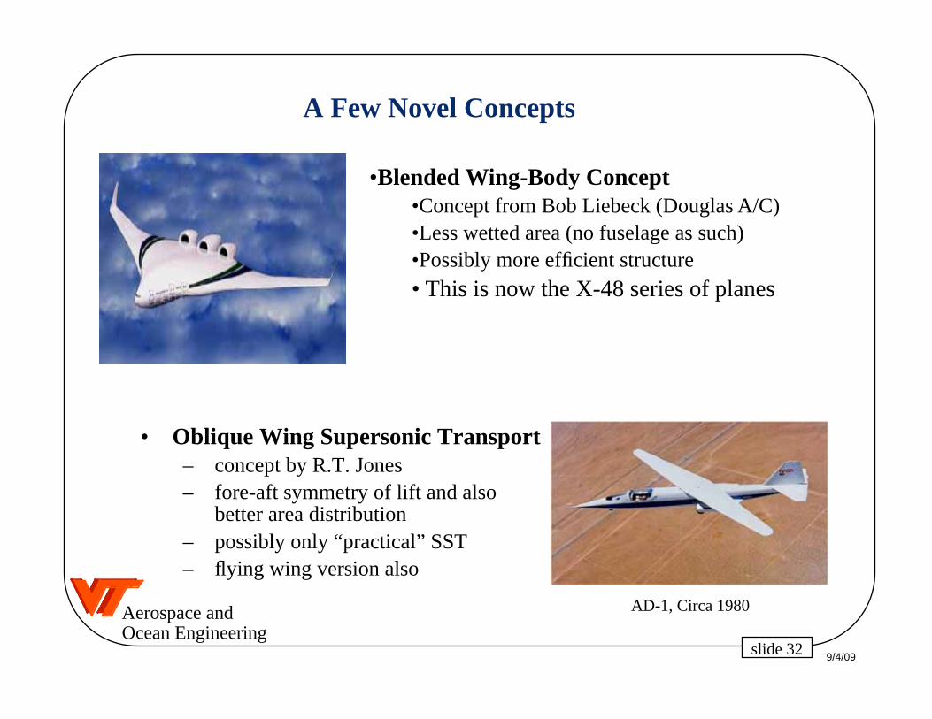
A Few Novel Concepts
• Oblique Wing Supersonic Transport– concept by R.T. Jones– fore-aft symmetry of lift and also
better area distribution– possibly only “practical” SST– flying wing version also
•Blended Wing-Body Concept•Concept from Bob Liebeck (Douglas A/C)•Less wetted area (no fuselage as such)•Possibly more efficient structure
• This is now the X-48 series of planes
AD-1, Circa 1980

9/4/09slide 33
Aerospace andOcean Engineering
Another Novel Concept: SpaceShipOne
Burt Rutan: Still imagineering!
The White Knight
SpaceShipOne
Pictures from the Scaled Composites web site

9/4/09slide 34
Aerospace andOcean Engineering
Our Current Favorite: the Strut Braced Wing
• The strut allows a thinner wing without a weight penalty
• Also a higher aspect ratio (span), less induced drag
• Reduced t/c allows less sweep without a wave drag penalty
• Reduced sweep leads to even lower wing weight
• Reduced sweep allows for some natural laminar flow
• reduced skin friction drag
• Werner Pfenninger’s strut-braced wing concept from 1954
• We need MDO to make it work
We are again working on this for NASA
See AIAA Paper 2005-4667
9/4/09slide 35
Aerospace andOcean Engineering
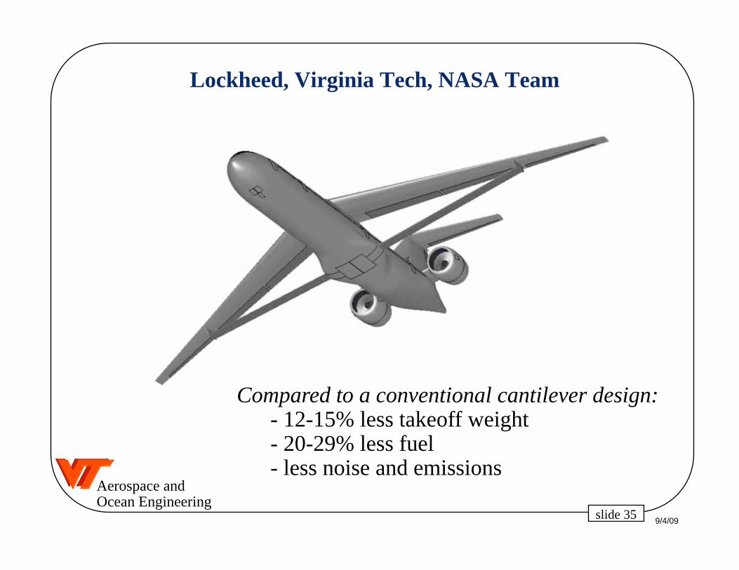
Lockheed, Virginia Tech, NASA Team
Compared to a conventional cantilever design:- 12-15% less takeoff weight- 20-29% less fuel- less noise and emissions

9/4/09slide 36
Aerospace andOcean Engineering
Today See AIAA Paper 2009-7114
Courtesy Ohad Gur

9/4/09slide 37
Aerospace andOcean Engineering
And Hope for Low-Sonic Boom Noise Flight
A modified F-5E demonstrated a low-noise boom on Aug. 27, 2003
So-called “boom shaping” can be used to reduce the part of the boom that hits the ground.
NASA Press Release,Sept. 4, 2003

9/4/09slide 38
Aerospace andOcean Engineering
The Latest: UCAVsThis one is based on
Nastasi/Kirschbaum/Burhans Patent 5,542,625
Northrop Grumman Corporation, reprinted by Aviation Week, June 16, 1997
The vertical tail is eliminated for stealth, directional controlcomes from specially coordinated trailing edge deflections

9/4/09slide 39
Aerospace andOcean Engineering
And finally, Micro AVs!
AeroVironment, Inc.
Black Widow
• 6-inch span fixed-wing aircraft
• Live video downlink
• Portable launch/control box• Pneumatic launcher
• 60 gram mass
• 22-minute endurance
• Estimated 10 km range
• Electric propulsion • World MAV endurance record of 22 minutes
• Smallest video camera ever flown on a UAV: 2 grams
• Smallest live video downlink ever flown on a UAV• World’s smallest, lightest multi-function, fully
proportional radio control system: 3 grams
• First aircraft to be flown “heads-down” indoors
Achievements
Joel Grasmeyer, MS VT 1998 - team member!

9/4/09slide 40
Aerospace andOcean Engineering
To Learn More, Read These:
The Anatomy of the Airplane, by Darrol Stinton. Few equations and deceptively simple, but it’s not. Lots of good information.
Design for Air Combat by Ray Whitford. Takes a deeper look at the details, again without equations and with lots of good graphics showing typical data to use deciding on design options. I continue to contend that the title suggests a much narrower focus than the book has.
Aircraft Design: A Conceptual Approach, by Daniel Raymer. Chapter 8, “Special Considerations in Configurarion Layout” and Chapter 22, “Design of Unique Aircraft Concepts” is good once you’ve read the first two references.
Airplane Design, Pt. II Preliminary Configuration Design etc., by Jan Roskam. Chapter 3, and 3.3 “Unusual Configurations”, in particular.

9/4/09slide 41
Aerospace andOcean Engineering
Still Room for Dreamers
We don’t yet know what the ultimate airplane concept is.
and concerning the comments on configurations given above,remember:
there is a time and place for everything
Next Time: How do we know how big to make the plane? Sizing