why do all those damned detectors look the...
TRANSCRIPT

1Jim Thomas
Why Do All Those Damned Detectors Look The Same?
Jim Thomas
ExtreMe Matter Institute / GSI & Lawrence Berkeley Laboratory
19-July-2010

2Jim Thomas
ATLAS vs PHENIX vs ….
They are about the same sizeThey are about the same shapeAre they really different?
PHENIX
ATLAS
Even fixed target detectors look like an angular slice of one of these detectors
3Jim Thomas
References
Outstanding References
• Fabio Sauli’s lecture notes on wire chambers (CERN 77-09)
• Particle Properties Data Booklet – Particle properties– Excellent summaries of particle detection techniques– http://pdg.lbl.gov to view the pages or order your own copy
• W. Blum, W. Riegler and L. Rolandi, “Particle Detection with Drift Chambers”, Springer, 2008.
This talk relied heavily on additional resources from the Web
• C. Joram – CERN Summer Student Lectures 2003• T.S. Verdee – SUSSP 2003• S. Stapnes – CERN School of Phyics 2002
4Jim Thomas
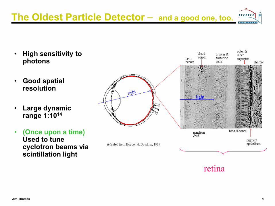
The Oldest Particle Detector – and a good one, too.
• High sensitivity to photons
• Good spatial resolution
• Large dynamic range 1:1014
• (Once upon a time)Used to tune cyclotron beams via scintillation light
retina
5Jim Thomas
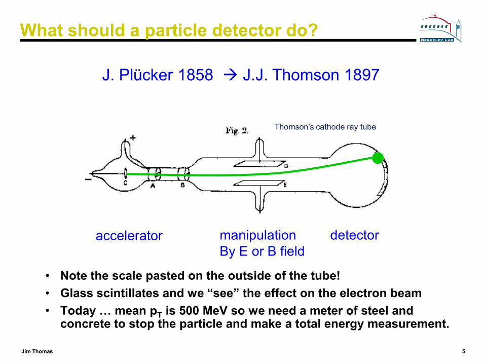
What should a particle detector do?
• Note the scale pasted on the outside of the tube!• Glass scintillates and we “see” the effect on the electron beam• Today … mean pT is 500 MeV so we need a meter of steel and
concrete to stop the particle and make a total energy measurement.
J. Plücker 1858 J.J. Thomson 1897
accelerator manipulationBy E or B field
detector
Thomson’s cathode ray tube
6Jim Thomas
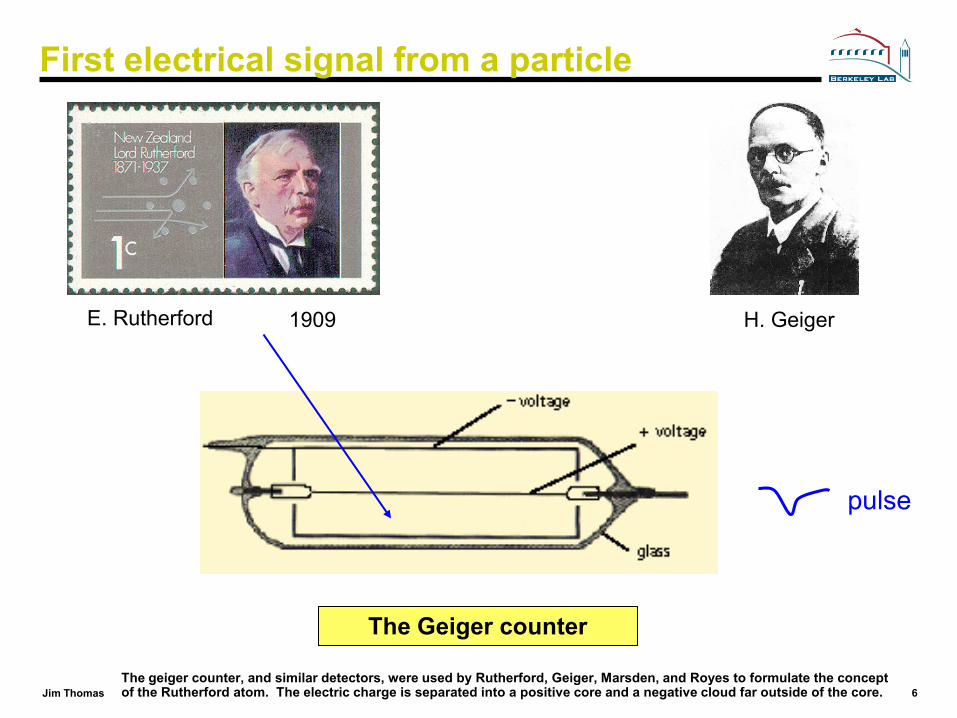
First electrical signal from a particle
E. Rutherford H. Geiger1909
The Geiger counter
pulse
The geiger counter, and similar detectors, were used by Rutherford, Geiger, Marsden, and Royes to formulate the concept of the Rutherford atom. The electric charge is separated into a positive core and a negative cloud far outside of the core.
7Jim Thomas
First tracking detector
C. T. R. Wilson, 1912, Cloud chamber
The general procedure was to allow water to evaporate in an enclosed container to the point of saturation and then lower the pressure, producing a super-saturated volume of air. Then the passage of a charged particle would condense the vapor into tiny droplets, producing a visible trail marking the particle's path.
8Jim Thomas
Detector Systems: Bubble Chambers
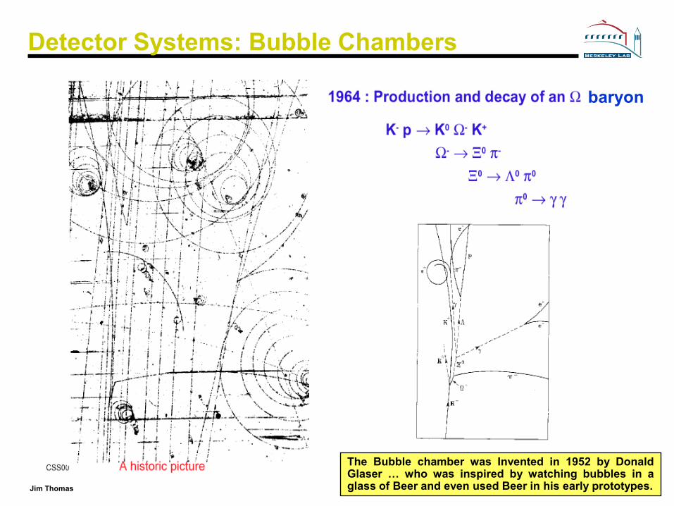
The Bubble chamber was Invented in 1952 by DonaldGlaser … who was inspired by watching bubbles in aglass of Beer and even used Beer in his early prototypes.
baryon
9Jim Thomas
Detector Philosophy
• Particles are detected by their interaction with matter
• Many different physical principals are involved– Electromagnetic– Weak– Strong– Gravity
• Most detection techniques rely on the EM interaction– Although, all four fundamental forces are used to measure and
detect particles
• Ultimately, we observe ionization and excitation of matter. In this day and age, it always ends up as an electronic signal.

10Jim Thomas
Ionization of gases
Fast charged particles ionize the atoms of a gas.
Often the resulting primary electron will have enough kinetic energy to ionize other atoms.
primarytotal nn ⋅≈ 43
Primary ionization Total ionization10 - 40 pairs/cm∆E/pair ~ 25 eV
Assume detector, 1 cm thick, filled with Ar gas:1 cm
~ 100 e-ion pairs
100 electron-ion pairs are not easy to detect!Noise of amplifier ≈ 1000 e- (ENC) !We need to increase the number of e-ion pairs.
11Jim Thomas
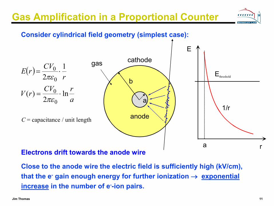
Gas Amplification in a Proportional CounterConsider cylindrical field geometry (simplest case):
a
b
r
E
1/r
a
cathode
anode
gasEthreshold
( )
arCVrV
rCVrE
ln2
)(
12
0
0
0
0
⋅=
⋅=
πε
πε
C = capacitance / unit length
Electrons drift towards the anode wire
Close to the anode wire the electric field is sufficiently high (kV/cm), that the e- gain enough energy for further ionization → exponential increase in the number of e--ion pairs.

12Jim Thomas
Avalanche form within a few radii or the wire and within t < 1 ns!Signal induction both on anode and cathode due to moving charges (both electrons and ions).
Signal Formation - Proportional Counter
drdrdV
lCVQdv
0=
Electrons are collected on the anode wire, (i.e. dr is small, only a few µm). Electrons contribute only very little to detected signal (few %).
Ions have to drift back to cathode, i.e. dr is big. Signal duration limited by total ion drift time !
We need electronic signal differentiation to limit dead time.
(F. Sauli, CERN 77-09)
(F. Sauli, CERN 77-09)
13Jim Thomas
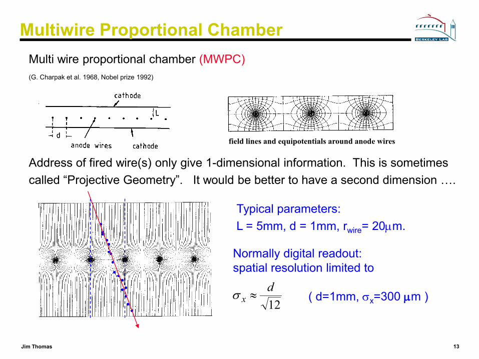
Multi wire proportional chamber (MWPC)(G. Charpak et al. 1968, Nobel prize 1992)
Address of fired wire(s) only give 1-dimensional information. This is sometimes called “Projective Geometry”. It would be better to have a second dimension ….
Multiwire Proportional Chamber
field lines and equipotentials around anode wires
Normally digital readout:spatial resolution limited to
12d
x ≈σ ( d=1mm, σx=300 µm )
Typical parameters: L = 5mm, d = 1mm, rwire= 20µm.
14Jim Thomas
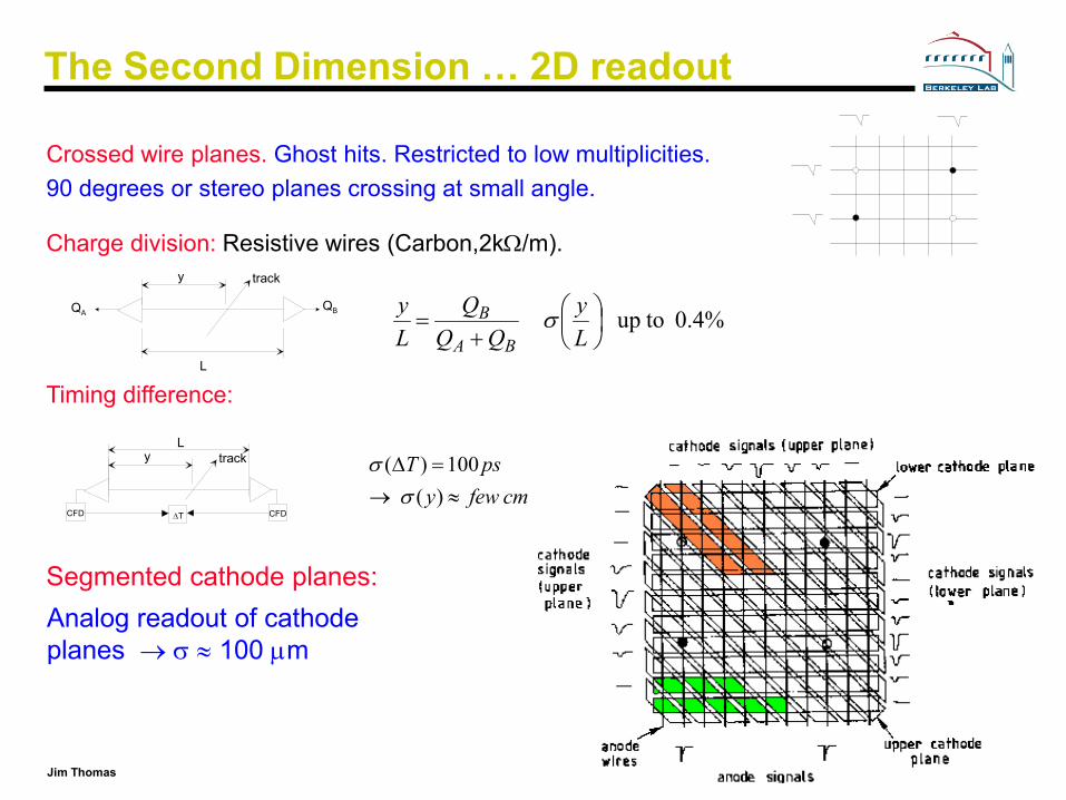
Charge division: Resistive wires (Carbon,2kΩ/m).
Timing difference:
Segmented cathode planes:
The Second Dimension … 2D readout
y
L
QBQA
track
%4.0 toup
+=
Ly
QQQ
Ly
BA
B σ
Crossed wire planes. Ghost hits. Restricted to low multiplicities. 90 degrees or stereo planes crossing at small angle.
yL
track
CFD CFD∆T
Analog readout of cathode planes → σ ≈ 100 µm
cmfewypsT
≈→=∆)(100)(
σσ
15Jim Thomas
The Third Dimension: Timing Difference
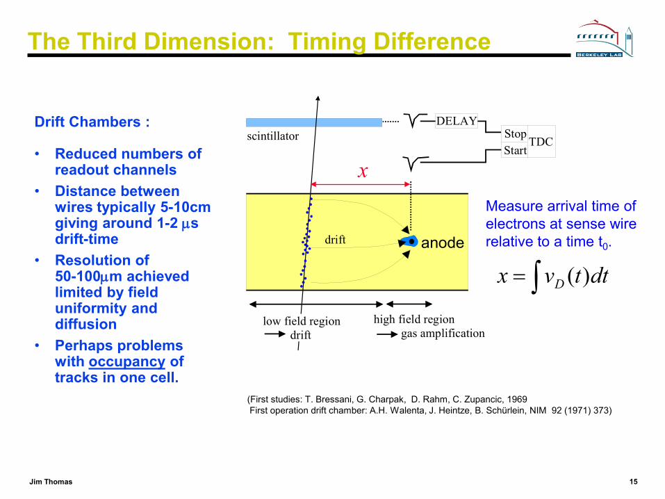
Drift Chambers :
• Reduced numbers of readout channels
• Distance between wires typically 5-10cm giving around 1-2 µs drift-time
• Resolution of 50-100µm achieved limited by field uniformity and diffusion
• Perhaps problems with occupancy of tracks in one cell.
Measure arrival time of electrons at sense wire relative to a time t0.anode
TDCStartStop
DELAYscintillator
drift
low field region drift
high field region gas amplification
dttvx D )(∫=
x
(First studies: T. Bressani, G. Charpak, D. Rahm, C. Zupancic, 1969First operation drift chamber: A.H. Walenta, J. Heintze, B. Schürlein, NIM 92 (1971) 373)
16Jim Thomas
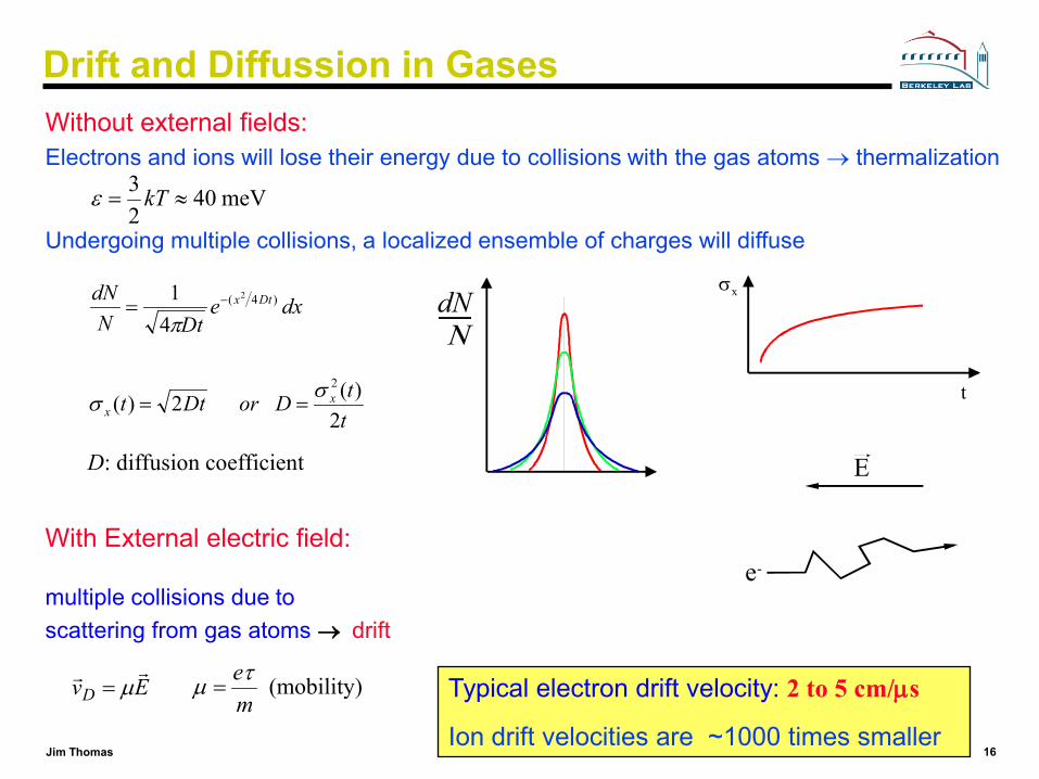
Drift and Diffussion in GasesWithout external fields:Electrons and ions will lose their energy due to collisions with the gas atoms → thermalization
Undergoing multiple collisions, a localized ensemble of charges will diffuse
ttDorDtt
dxeDtN
dN
xx
Dtx
2)( 2)(
41
2
)4( 2
σσ
π
==
= −
D: diffusion coefficient
meV4023
≈= kTε
t
σxdNΝ
With External electric field:e-
Ε
EvD µ= (mobility)
meτµ =
multiple collisions due to scattering from gas atoms → drift
Typical electron drift velocity: 2 to 5 cm/µs
Ion drift velocities are ~1000 times smaller
17Jim Thomas
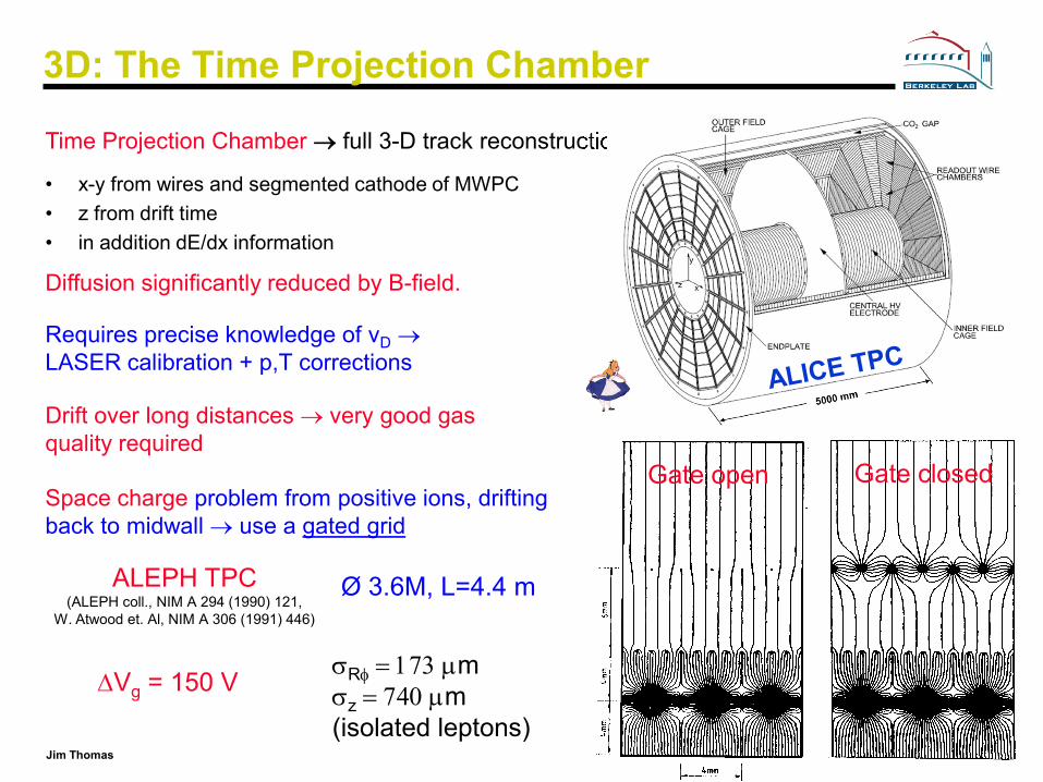
3D: The Time Projection Chamber
Time Projection Chamber → full 3-D track reconstruction
• x-y from wires and segmented cathode of MWPC• z from drift time• in addition dE/dx information
Diffusion significantly reduced by B-field.
Requires precise knowledge of vD →LASER calibration + p,T corrections
Drift over long distances → very good gas quality required
Space charge problem from positive ions, drifting back to midwall → use a gated grid
Gate open Gate closed
∆Vg = 150 V
ALEPH TPC(ALEPH coll., NIM A 294 (1990) 121,
W. Atwood et. Al, NIM A 306 (1991) 446)
Ø 3.6M, L=4.4 m
σRφ = 173 µmσz = 740 µm(isolated leptons)
18Jim Thomas
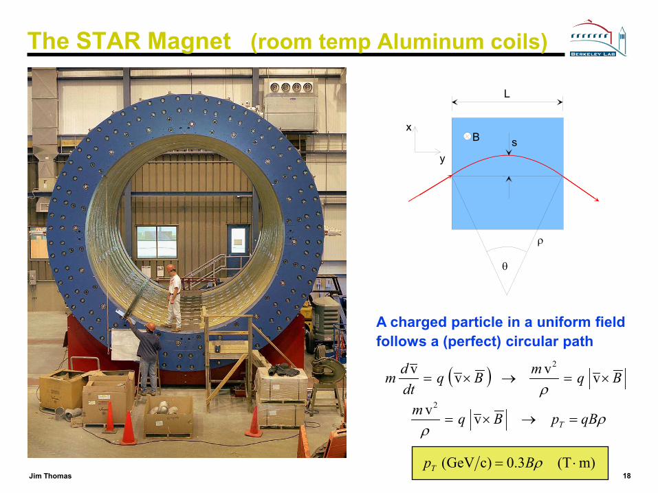
The STAR Magnet (room temp Aluminum coils)
L
ρ
s
θ
B
y
x
( ) BqmBqdtdm ×=→×= vvvv 2
ρ
m)(T3.0)cGeV( ⋅= ρBpT
A charged particle in a uniform field follows a (perfect) circular path
ρρ
qBpBqmT =→×= vv2
19Jim Thomas
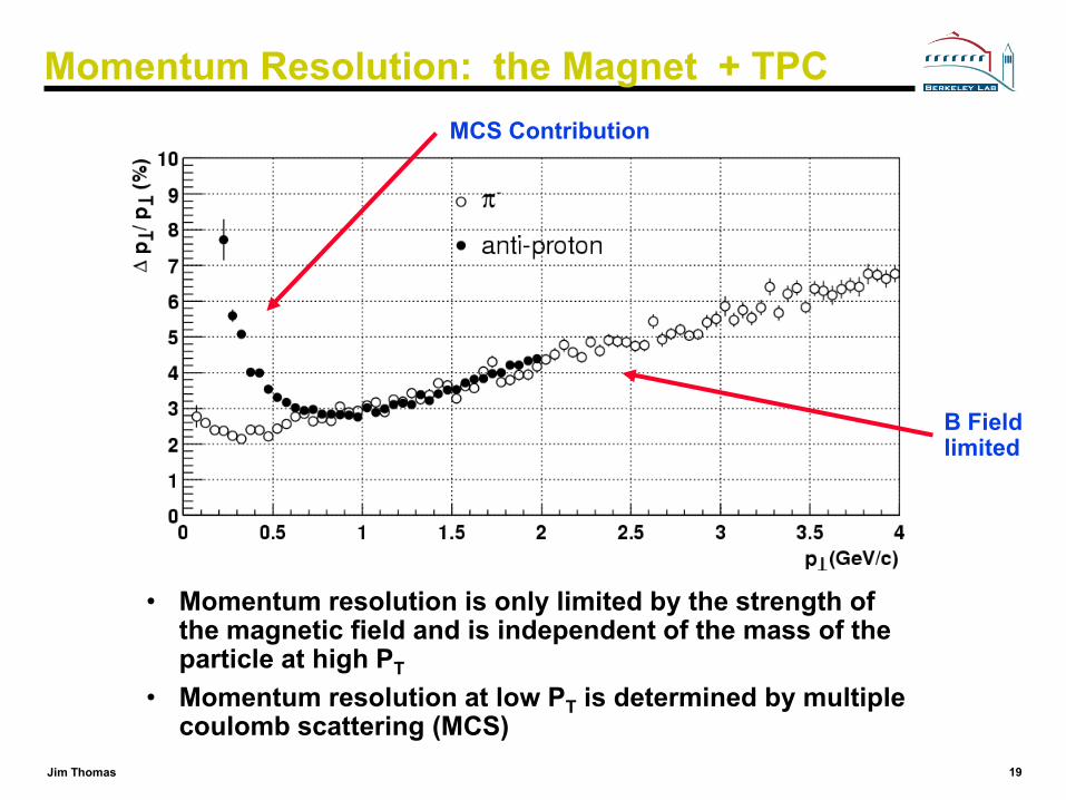
Momentum Resolution: the Magnet + TPC
• Momentum resolution is only limited by the strength of the magnetic field and is independent of the mass of the particle at high PT
• Momentum resolution at low PT is determined by multiple coulomb scattering (MCS)
MCS Contribution
B Field limited
20Jim Thomas
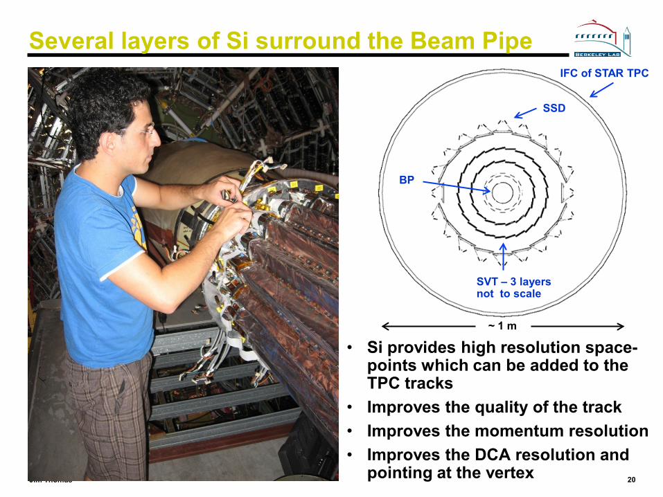
Several layers of Si surround the Beam Pipe
• Si provides high resolution space-points which can be added to the TPC tracks
• Improves the quality of the track• Improves the momentum resolution• Improves the DCA resolution and
pointing at the vertex
IFC of STAR TPC
SSD
BP
SVT – 3 layersnot to scale
~ 1 m
21Jim Thomas
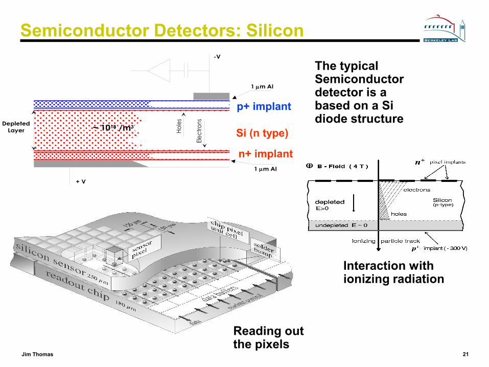
Semiconductor Detectors: Silicon
1 µm Al
+ V
DepletedLayer
1 µm Al
Elect
rons
Hole
s
~ 1018 /m3
-V
p+ implant
n+ implant
Si (n type)
Interaction with ionizing radiation
Reading out the pixels
The typical Semiconductor detector is a based on a Si diode structure
22Jim Thomas
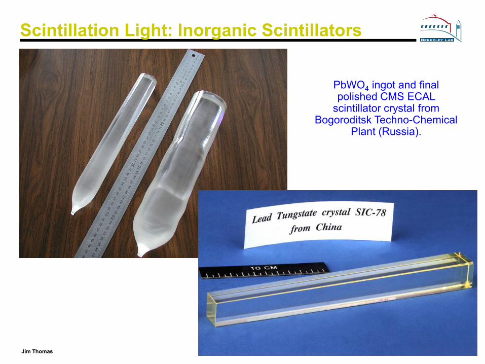
Scintillation Light: Inorganic Scintillators
PbWO4 ingot and final polished CMS ECAL
scintillator crystal from Bogoroditsk Techno-Chemical
Plant (Russia).
23Jim Thomas
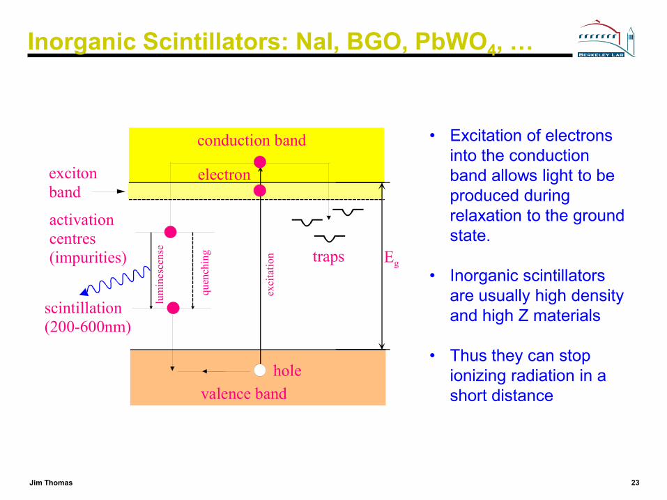
Inorganic Scintillators: NaI, BGO, PbWO4, …
• Excitation of electrons into the conduction band allows light to be produced during relaxation to the ground state.
• Inorganic scintillators are usually high density and high Z materials
• Thus they can stop ionizing radiation in a short distance
conduction band
valence band
Egtraps
activationcentres(impurities)
lum
ines
cens
e
quen
chin
g
hole
electron
scintillation(200-600nm)
exci
tatio
n
excitonband

24Jim Thomas
Scintillation Light: Organic Scintillators
• Liquid and plastic organic scintillators are available
• They normally consist of a solvent plus secondary (and tertiary) fluors as wavelength shifters.
Molecular states
singlet states
triplet states
S0
T1
T2S1
S2
S3
singlet states
triplet states
S0
T2S1
S2
S3
non-radiative
fluorescence10-8 - 10-9 s
phosohorescence>10-4 s
10-11 s

25Jim Thomas
Photo detector
primary particle
UV (primary)
blue (secondary)
greensmall air gap
scintillator
WLSPhotoDetector
Scintillator Readout Schemes
Geometrical adaptation:
Light guides: transfer by total internal reflection (+outer reflector)
Wavelength shifter (WLS) bars
“fish tail” adiabatic
26Jim Thomas
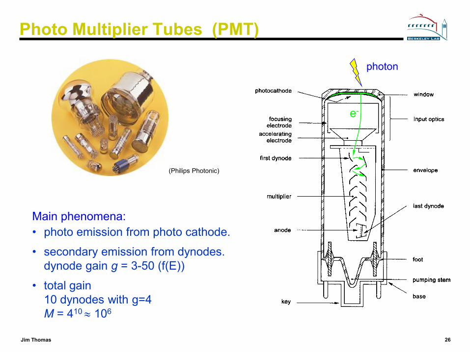
Photo Multiplier Tubes (PMT)
Main phenomena:• photo emission from photo cathode.
• secondary emission from dynodes. dynode gain g = 3-50 (f(E))
• total gain 10 dynodes with g=4M = 410 ≈ 106
e-
photon
(Philips Photonic)
27Jim Thomas
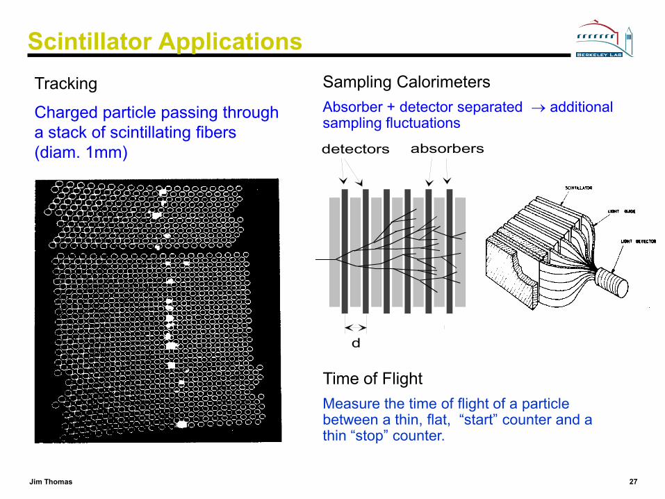
Scintillator ApplicationsTracking
Charged particle passing through a stack of scintillating fibers(diam. 1mm)
Sampling CalorimetersAbsorber + detector separated → additional sampling fluctuations
detectors absorbers
d
Time of FlightMeasure the time of flight of a particle between a thin, flat, “start” counter and a thin “stop” counter.

28Jim Thomas
150 GeV Pion Showers in Cu
Hadron shower not as well behaved as an em one
Hadron calorimeter are always sampling calorimeters
29Jim Thomas
Lets Design a Detector: Requirements
Very good particle identificationtrigger efficiently and measure ID and momentum of all particles
High resolution electromagnetic calorimetry
Powerful inner tracking systemsImproves momentum resolution, find tracks of short lived particles
Hermetic coveragegood rapidity coverage, good missing ET resolution
Affordable detector

30Jim Thomas
‘Cylindrical Onion-like’ Structure of HE Detectors
Central detector • Tracking, pT, MIP
• Em. shower position • Topology
• Vertex
Electromagnetic and Hadron calorimeters • Particle identification (e, γ Jets, Missing ET) • Energy measurement
Each layer identifies and enables the measurement of the momentum or energy of the particles produced in a collision
µµnn
pp
γγ
Heavy materials
νν
Heavy materials (Iron or Copper + Active material)
ee
Materials with high number of protons + Active material
Light materials
Muon detector • µ identification
Hermetic calorimetry • Missing Et measurements

31Jim Thomas
The CMS Detector

32Jim Thomas
The ATLAS Detector
Diameter 25 m End-cap end-wall chamber span 46 mBarrel toroid length 26 m Overall weight 7000 Tons
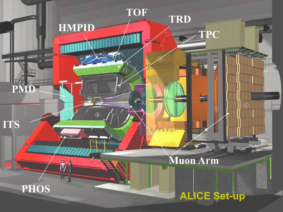
33Jim Thomas 33ALICE Set-up
HMPID
Muon Arm
TRD
PHOS
PMD
ITS
TOF
TPC
34Jim Thomas
Conclusions
• We have taken a random walk through a variety of detector technologies and put the pieces together into a detector
• You can repeat this exercise using the PDG booklet or BRR– It contains a wealth of information– It is extremely well written and only contains the most essential
information
• The design of HEP and HENP detectors is driven by the desire to measure the ID and momentum of all particles in the range from 100 MeV to 100 GeV.
– all 4 components of the momentum 4-vector (E, px, py, pz)– all 4 components of the spacial 4-vector (ct, x, y, z)
• If you can afford to do this with full 4π coverage, then your detector will end up looking pretty much like all the other big detectors. However, there are big differences in the details and cost effectiveness of each detector design.