why should plumbing designers embrace revit? - ghtltd.com · ˜ learn the advantages of autodesk...
TRANSCRIPT

36 Consulting-Specifying Engineer • AUGUST 2013 www.csemag.com
Building information modeling (BIM) is a powerful tool that is trans-forming the design and construc-
tion industry. As more building owners become familiar with the technology and even mandate its use, successful architec-ture, engineering, and construction (AEC) firms understand that they must embrace the BIM revolution if they want to stay competitive and keep pace with industry trends. Consulting engineers need vision and commitment to integrate BIM into their practice as it matures for mechani-cal, electrical, plumbing (MEP), and fire protection design.
Across the MEP disciplines, design-ers voice common challenges related to BIM. MEP software is typically a gen-eration or two behind software for struc-tural engineering, and further behind that for architects. Designers need intensive training to start using it, and the skills they develop are of the “use it or lose it” variety. Breakdowns in project team communication can jeopardize drawing quality and project schedules. However, with upfront planning and a focus on collaboration, there are solutions. The plumbing discipline has the farthest to go in terms of software development, but there are a few simple shifts that design-ers can make to dramatically increase productivity.
Don’t let the learning curve of imple-menting BIM distract you from the big-ger picture. The use of 3-D modeling software creates deeper project knowl-edge, delivers a more robust product, and can reduce total project costs.
Big-picture guidelines GHT Limited, Arlington, Va., uses
Autodesk Revit MEP software. It’s important for designers to understand that Revit functions very differently from AutoCAD—it’s not just a 3-D version
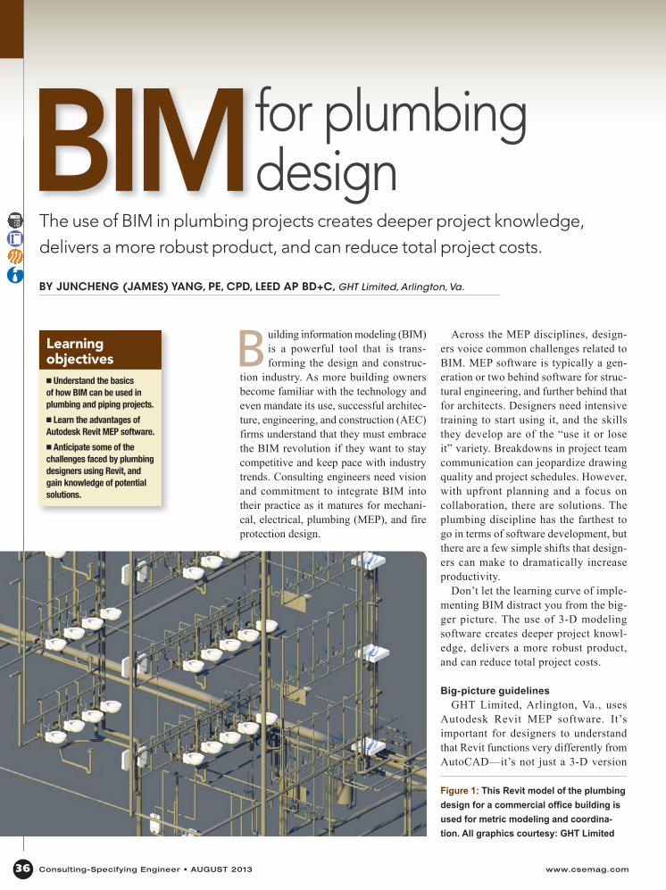
Figure 1: This Revit model of the plumbing design for a commercial office building is used for metric modeling and coordina-tion. All graphics courtesy: GHT Limited
The use of BIM in plumbing projects creates deeper project knowledge, delivers a more robust product, and can reduce total project costs.
BY JUNCHENG (JAMES) YANG, PE, CPD, LEED AP BD+C, GHT Limited, Arlington, Va.
BIMLearningobjectives� Understand the basics of how BIM can be used in plumbing and piping projects.
� Learn the advantages of Autodesk Revit MEP software.
� Anticipate some of the challenges faced by plumbing designers using Revit, and gain knowledge of potential solutions.
for plumbing design

of the drafting software. In addition to the X and Y coordinates, you have the Z coordinate and material data collection information, as well as the potential to integrate time, cost, and lifecycle man-agement data. Designers must show the plan view of X and Y; the Z coordinate will be decided by the cut plan view set by the user.
One of Revit’s unique features is the Families function. Families are divided into three groups. The first group is the System Families, which are pre-existing within the software. The second group is the Loadable Families. This group is customized by the user, based on the project needs. The third group is the In-Place Families, which are loadable but can’t be exported out of the project in which they were made. All families have one thing in common: They are 3-D para-metric objects.
Traditionally designers draw a rectan-gle, square, circle, or other type of shape to represent an object for 2-D Auto-CAD drafting. Some of these objects are available in Revit format from the material or equipment manufacturer, but not always—design teams should check availability at the beginning of the proj-ect and plan to create them in-house if they don’t exist yet. Be aware that when an object is provided by the manufac-turer, it may contain much more informa-tion than what you require, which may slow down productivity due to the files’ large size. As software development is progressing, firms should plan to allow design teams research and development time for creating efficiencies for their Revit projects, which will cut costs in the long run.
Owners are understandably excited about BIM software, though they are not always aware of how its use will affect the project budget and scope, leading to challenges later in the job. Engineering consultants can make the process more successful by educating their clients about the impacts of using BIM during the proposal and negotiation stage. Help them understand the benefits they will gain to offset their concerns that it might
add a premium. To support this effort, designers must vocalize how the use of BIM impacts their workflow to their firm’s executives.
Revit is a collaborative tool, so allo-cate time for collaboration. The use of Revit typically requires more team coor-dination than do projects in AutoCAD, and this should be reflected in project planning and cost estimating for design. On a Revit project, getting consultants on board and involved earlier in the project, potentially in the concepts or schematics
phase instead of the design-development phase, should lead to a better coordinated finished model, resulting in fewer prob-lems during construction.
Revit design tips for plumbing designPlumbing design can be more com-
plicated in Revit than HVAC or electri-cal design because it deals with sloped piping, a sanitary drain vent, storm drain lines, and so on. The latest ver-sions of Revit have improved the ability to design sloped piping, though it can
37www.csemag.com Consulting-Specifying Engineer • AUGUST 2013
Figure 2: The cylinders on the bottom left show placeholder objects for equipment not available in a Revit loadable family.
Why should plumbing designers embrace Revit?n Creates an opportunity for the designer to better understand the design.
n Delivers a single model with dynamic views you can customize to show specific compo nents, such as a lighting plan, ceiling to slab view, large mechanical spaces, central plants, and ceiling plenums. Sections can be cut and displayed quickly for any area as a result of the comprehensive information available in the model.
n Allows designers the ability to make a change in one place and have that change automati cally and immediately replicated in every place it should occur throughout the model.
n Offers the capability to pull data like fixture units and flow for sizing.
n Provides the ability to set up typical design and document schedules that can rapidly increase documentation time.
n Gives designers the functionality to create Groups of typical connections that can be designed and copied to other floors, as well as to reuse data-rich plumbing Families that can cut future Families development time.
n Delivers a higher level of model detail when using manufacturer-specific fittings and accessories.
n Offers systems data that provides in-depth detail of pipe length and fitting sizes for crucial mechanical equipment selections for hospitals and labs.
n Supports working in a collaborative model that forces interdisciplinary coordination, which ultimately produces a better product for the owner.

38 Consulting-Specifying Engineer • AUGUST 2013 www.csemag.com
be time consuming if you need to con-nect multiple sloped pipes together and retain the slope with the correct fittings. The plumbing design also requires lots of piping in small spaces. In addition, plumbing design in AutoCAD is typical-ly schematic in nature, so it requires a shift in mind-set for designers to start thinking of their components as real-life objects and how they will be installed during construction.
Here is some advice on common situations plumbing designers face in Revit.
Time savers: Designers transition-ing to Revit often comment that it takes more time to accomplish a task in Revit than it does in AutoCAD. Consider the following to shave time from your workflow:
n Revit is a graphical database. Plumbing involves repetitive design components, so if you save common designs in groups you can reuse them on future projects—similar to blocks in AutoCAD. In Revit, it can be faster to reconfigure the design than to start from scratch. GHT Limited’s team designed a standard pump room with all the components and piping in Revit, and created a group. Copying this standard into new projects and reconfiguring it has saved us many billable hours when the building types are similar. As we all know, no two buildings are exactly alike when it comes to the layout and util-ity connections, though in many cases you should be able to use similar types of pumps, fittings, and accessories.
n If you’re under deadline pressure and have to delegate plumbing work to col-leagues who are not proficient in Revit, they can draw in CAD and the files can be linked to a drafting view, and later incor-porated into Revit. Any changes required on the CAD file can be made in the CAD file, and you can manage the link to Revit for automatic updates. This is most help-ful if you are new to using Revit and are under pressure to get your portion com-pleted on time. Once you become more
efficient in Revit, we would recommend avoiding this practice, as it can decrease the operational speed of the overall Revit model and reduce productivity. In addi-tion, we have found difficulties with plotting sheets linked in from CAD with
respect to fonts and other items that are not necessarily compatible with Revit.
n Drafting views create a view show-ing details that are not directly associ-ated with the building model, like riser diagrams and detail sheets. This approach works well for supporting information, like riser diagrams, cover sheets, and details.
n Revit lets you design pipe placehold-ers. This is especially helpful for large buildings; you can simply touch a button and they update throughout the model. However, many users have found it more useful to complete the work within
standard Revit piping systems and change pipe sizes as required by selecting indi-vidual sections or whole systems in place of this element. In addition, we recom-mend using placeholders only during the schematic design phase.
n If you have a pipe that runs above and below the floor, the pro-gram has tools that make it easy to tap into pipes at the same and differ-ent elevations. It also has a visibility that shows when piping is below the view range; this is discussed in more detail in the section on visibility
n Typically you won’t know all pipe sizes until the layout is finished, but that doesn’t mean you should wait to get started until the end of the design process. Tag each pipe with an esti-mated size before you exit your draw-ing; when you go back, you can quick-ly update the information if necessary
n Practice every day whether you’re working on a Revit job or not. Even spending 10 minutes a day using Revit can help you maintain your skills, and reduce retraining time in the future
Visibility: Some plumbing design-ers express difficulty with graphics and visibility, especially in regard to printing, with Revit. Part of the solu-tion lies in your view and workset:
n Elements can be hidden or misplaced outside the floor plans. Adjusting visibility graphics allows you to cut the view depth lower
than the floor plan. For example, the standard view will not show a drain in the slab. To make it show up, set the visibility view depth lower. You can extend the view into “beyond” mode, which changes line work—a dashed line means it’s not on that level, but it does exist. This may also result in structural or architectural elements showing up along with the below-slab piping. Be aware that this may cause plotting and clarity issues with the drawings when submitted to the authority having juris-diction (AHJ) or the owner. An alternate solution would be to modify the hidden
BIM for plumbing design
Figure 3: Vertical plumbing in a tight space is shown in this installation model.

BIM for plumbing design
object by extending it above the floor in order to achieve the visibility.
n Make sure you are in the correct workset. Use filters to display plumbing equipment and pipes in the plumbing views, add all of your components to the plumbing workset, and complete all design in that space. This will enable you to print only the components you want to see and filter out what you don’t want to see.
n Using the underlay option in the properties dialogue box while in a floor plan allows you to see a phantom view of piping or equipment below the floor level you are working in. This is helpful for coordination and layout of pipe runs and riser locations, as well as avoiding conflicts
Connections: In Revit, plumbing connections are typically shown on the MEP model, not the architect’s model. When an architect updates the model and moves a restroom or deletes a wall, the MEP model assumes the plumbing host is still there. As a result, Revit won’t allow the modification. You can’t just “grab and rotate” the plumbing when an architectural change happens; you have to redo the connections. To speed this process:
n Create a Group and keep it in general relationships; don’t connect directly to fixtures until the architect tells you that no more changes will be made, to avoid having to disconnect and
reconnect all piping. We consider it a best practice to not host plumbing piping on objects, as it can save significant time when the architectural background model changes.
n Remember to pay attention to deliverables. It’s not always cost-effective to show every single plumbing connection in Revit, especially for projects where you anticipate a lot of last-minute changes. Waiting to make final connections until floor plan deci-sions are reasonably complete adds order and flexibility.
Document coordination versus full documentation: There are times when it is appropriate to use Revit for document coor-dination rather than full documentation. The most important fac-tor in success with this approach is making that decision at the beginning of the job. The cost to fix plumbing mistakes later is comparably high, because water goes through the entire building and can’t be modified in sections. The project team and owner must be on the same page from day one; they must agree on the approach and stick with it.
n Before beginning the design, ask what level of detail is required and clarify the deliverable. Can modeling stop below 2-in. diameter pipe? Can it be performance based? The plumbing only needs to be defined as far as the subcontractor will need it to install, some of which can be done in AutoCAD.
n In our experience, full Revit documentation has worked best on complicated projects where many changes are expected. When using Revit for document coordination only, be strategic in identifying the areas that typically present clash problems. The MEP can’t be fully responsible for all areas due to the lack of exact materials, lack of control over the installation sequence that occurs in the field, and level of contractor experience
n Either way, the use of Revit allows contractor questions to be answered more quickly, because there is more infor-mation about the design. The model allows you to visualize the final product on the screen before it’s constructed in the field. And as the level of detail in Revit increases, the speed follows suit. Theoretically, the use of BIM should result in a much better coordinated set of plans which, in turn, should minimize requests for information (RFI) during construction and help keep the project on time and budget.
n Revit also provides a benefit in coordinating with other disciplines. Sloping pipes take up a lot of room in the ceiling plenum, where everyone’s fighting for space. Revit can make collaboration easier for plumbing designers, as they can see the ductwork, cable trays, etc., that are already there, and help the architect set the final ceiling height throughout the building. Ceiling plenum coordination is a significant benefit in areas like Washington, D.C., where height limits put ceiling space at a premium.
Juncheng (James) Yang is a Senior Associate and Plumbing Section Head at GHT Limited. He has more than 15 years of experience delivering highly creative, technically exceptional plumbing designs for commercial, governmental, and institu-tional projects.
The 100% pre-tested, pre-assembled,
seismic-ready jointIt’s goof-proof.No assembly required. You know it will work. Get the details atwww.MetraFire.com
©20
12 T
he M
etra
fl ex
Co
mp
any
Revit®...Revit®
CAD drawings online
1-800-FIRELUP • 1-855-347-3587
input #19 at www.csemag.com/information