why use a small 8-bit processor when there are cheap ... · why use a small 8-bit processor when...
TRANSCRIPT

Why use a small 8-bit processor when there are cheap powerful
32-bit?
William Sandqvist [email protected]

8-bit processor close to the sensor?
William Sandqvist [email protected]
• A simple sensor often has a weak output signal. It may need to be connected with an expensive cable.
• An expensive sensors with "integrated electronics" can get by with a simple cable.
The cost of both options can very well end up to be the same!
Thus smart to embedd an 8 bit processor inside the sensor!
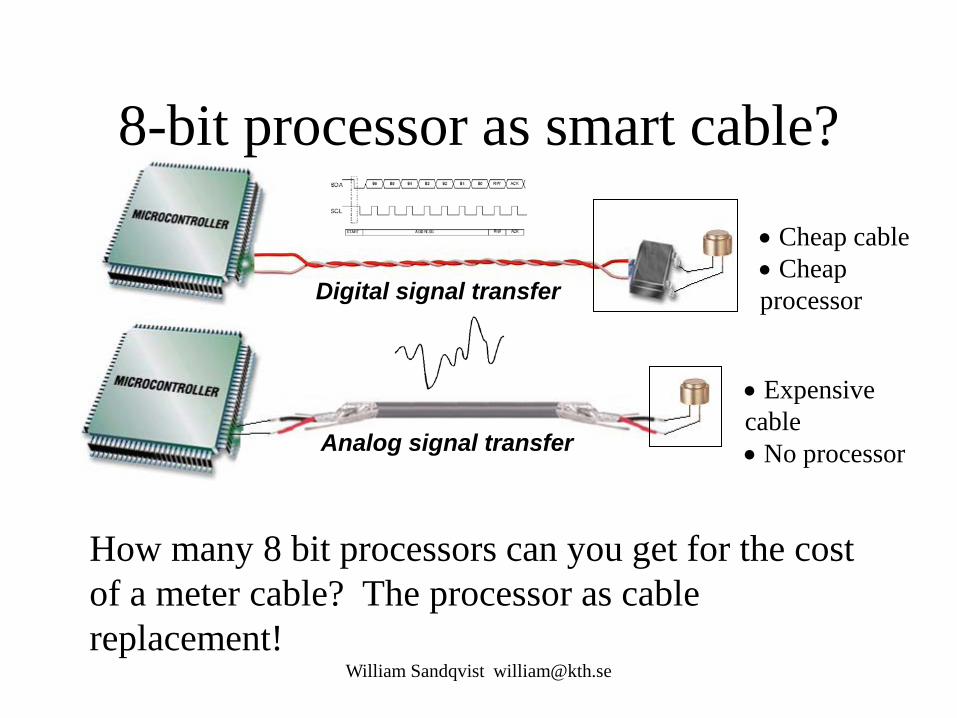
8-bit processor as smart cable?
William Sandqvist [email protected]
How many 8 bit processors can you get for the cost of a meter cable? The processor as cable replacement!
Analog signal transfer
Digital signal transfer
• Cheap cable • Cheap processor
• Expensive cable • No processor

William Sandqvist [email protected]
PIC 8-bit processor
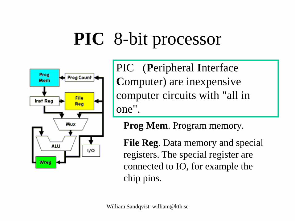
PIC (Peripheral Interface Computer) are inexpensive computer circuits with "all in one".

• Different number of pins
• Different combi- nations Of IO-units
• Different amount of program memory • different amount of data memory
PIC Midrange processor
63 different typs of Midrange PIC processors!

The business idea - buy only as much as you need
Develop your application on a processor with "little of everything".
To the finished product then use just exactly how much you need.
William Sandqvist [email protected]

ELFA’s cheapest PIC-processor
William Sandqvist [email protected]
4 kr each if you buy 10 …
Programmemory: 384 words RAM-memory: 16 Byte 8 bit AD-converter 2 channels Internal oscillator 4 MHz TIMER0 Voltage 2…5,5 V Typical current consumption: 175μA
PIC10F220T-I/OT Can be compiled with Cc5x – includefile exist
When computing power is so cheap there opens up completely new possibilities…
This is one reason why it might be good idea to learn PIC processors!

The built in IO devices increases 8-bit processors' performance
William Sandqvist [email protected]
IO ports and IO bits, timers, Capture/Compare/PWM, Analog comparators, ADC, Serial ports, voltage references, data EEPROM, etc.


The course is all about connecting electronics to the IO devices
William Sandqvist [email protected]
How to indicate that a coin is nearby (the coil)?
• CCP-unit
• LC-oscillator
Circuit Theory and PIC processor!

You will, for example, get to know how an inductive sensor works…

William Sandqvist [email protected]
PIC 8-bit processor PIC (Peripheral Interface Computer) are inexpensive computer circuits with "all in one".
Prog Mem. Program memory.
File Reg. Data memory and special registers. The special register are connected to IO, for example the chip pins.
William Sandqvist [email protected]
Program memory
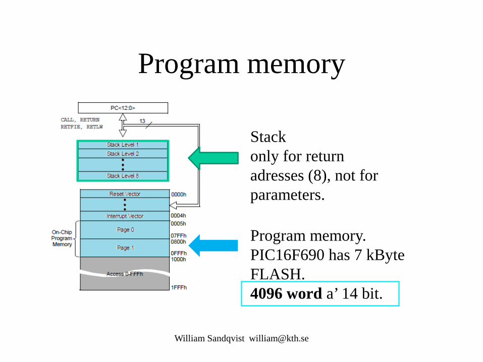
Stack only for return adresses (8), not for parameters.
Program memory. PIC16F690 has 7 kByte FLASH. 4096 word a’ 14 bit.

William Sandqvist [email protected]
16F690 Program memory PIC-processor GOTO and CALL -instructions can directly reach addresses within 2 k (opcode has 11 addressbits).
16F690 has 4 k program memory, so one has to choose new ”page” in the program-memory.
The division in pages, is an outdated architecture.
William Sandqvist [email protected]
Code pages PIC processors have the program memory divided into ”code pages"? (0, 1, 2, 3), about 2048 instructions. The compiler Cc5x begins to put code on page 0 and gives error when this page is not enough. Should this occur you write there instructions? #pragma codepage 1, then further instructions end up on the next page (and so on code page 2 if necessary).
To get compact code a thorough ”page planning ” is needed, something that one hardly cares about during prototype development.

William Sandqvist [email protected]
Data memory register File
PIC processor data memory is the Register File. It consists of SFR, special function registers, and the GPR General-purpose registers which are the actual data memory. SFR registers are connected to the processor IO. Mapped RAM, same register is found in all banks - you do not have to change rambank!

William Sandqvist [email protected]
RP1 and RP0 One chooses bank with the bits RP1 and RP0 in STATUS register
The division of data memory in RAM banks is an outdated architecture.

William Sandqvist [email protected]
The compiler can choose for us! The PIC processor's register area (RAM) is divided into "ram banks" (0, 1, 2, 3). Cc5x begins to fill rambank 0. You can change rambank with instruction #pragma Rambank 1 and then all variables that are declared are placed in the next rambank (rambank 1). Some memory cells are found in the same place in all ram banks, known as mapped RAM. You can choose to place variables as "mapped ram" (as long as there is space) with the instruction #pragma rambank -.
Best use of RAM banks requires a lot of planning, something one hardly cares about during prototype development.
William Sandqvist [email protected]
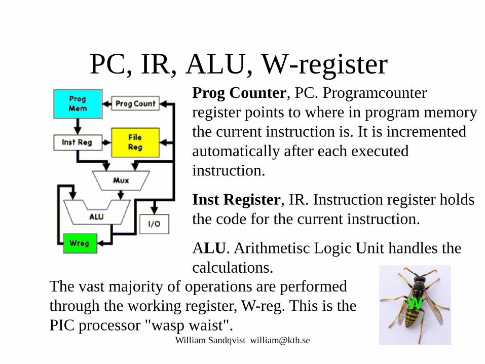
PC, IR, ALU, W-register Prog Counter, PC. Programcounter register points to where in program memory the current instruction is. It is incremented automatically after each executed instruction.
Inst Register, IR. Instruction register holds the code for the current instruction.
ALU. Arithmetisc Logic Unit handles the calculations.
The vast majority of operations are performed through the working register, W-reg. This is the PIC processor "wasp waist".
W

William Sandqvist [email protected]
Harvard vs Von Neumann
• Von Neumann architecture have a common bus for instructions and data.
• Harvard architecture has different busses for instruc- tions and data. Harvard is (twice) faster …

William Sandqvist [email protected]
CISC vs RISC • CISC (Complex Instruction Set Computer) Eg. Intel PC, has 700 instructions.
• RISC (Reduced Instruction Set Computer) Eg. Microchip PIC, has 33 instructions.
These concepts are now obsolete. Intel processors are still classified as CISC - but they have advanced architecture that utilizes all the best of RISC…

William Sandqvist [email protected]
KIA’s factory in Slovenia A car every minute is leaving the band – does it take one minute to build a car? No at KIA's factory outside Zilina it will take 18 manhours to build a car (this is worldrecord! Toyota will need 30 manhours).
The solution is a Pipeline. 18 hours is 1080 minuts, så build is done in parallell at 1080 one minute stations. The factory has 3000 employees working in three shifts, ie 1000 workers per shift. Many of the station are thus completely robotized.
William Sandqvist [email protected]
Fetch and Execute
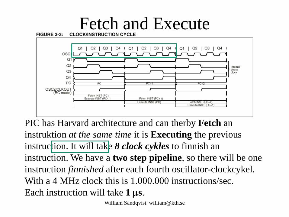
PIC has Harvard architecture and can therby Fetch an instruktion at the same time it is Executing the previous instruction. It will take 8 clock cykles to finnish an instruction. We have a two step pipeline, so there will be one instruction finnished after each fourth oscillator-clockcykel. With a 4 MHz clock this is 1.000.000 instructions/sec. Each instruction will take 1 µs.
William Sandqvist [email protected]
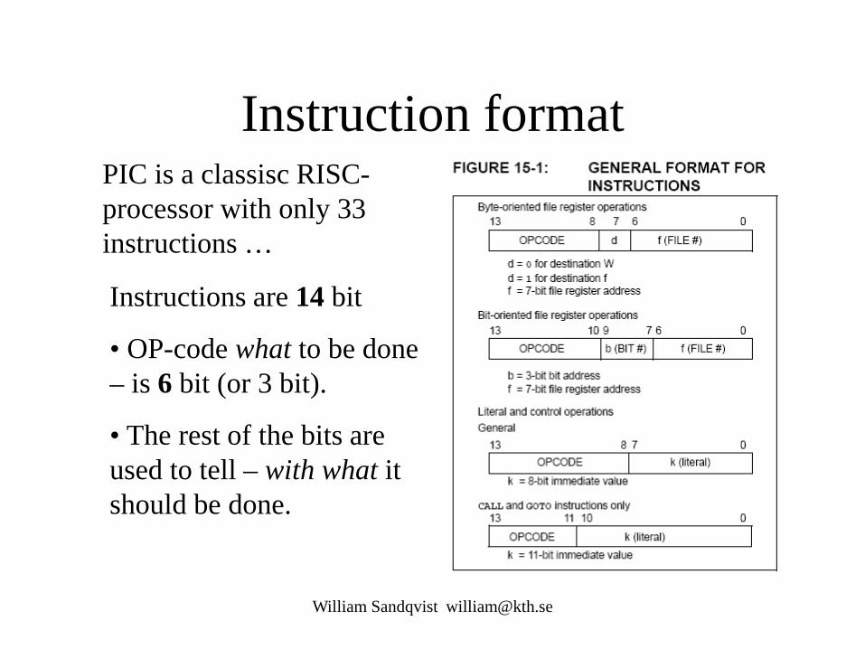
Instruction format PIC is a classisc RISC-processor with only 33 instructions …
Instructions are 14 bit
• OP-code what to be done – is 6 bit (or 3 bit).
• The rest of the bits are used to tell – with what it should be done.

William Sandqvist [email protected]
Byte operations Ex. Addition of numbers in FILE, data memory, and working-register W. The result is stored lagras in workingregister or data memory – and the initial number will be overwritten. ADDWF f,d ADDWF f,0; W=f+W eller ADDWF f,1; f=f+W
In the same way: SUBWF f,d
Assembler instructions are written as easy to remember abbreviation mnemonics.

William Sandqvist [email protected]
More Byte operations
If you want to copy content between the memory and the working register one does it with MOVF f,0; W=f or between working register and memory with MOVWF f; f=W
Some special cases of addition and subtraction, increase by one respective decrease by one, have their own instructions. Like the reset of register.
INCF f,d DECF f,d CLRW resp CLRF f
Move mean really Copy!

William Sandqvist [email protected]
Program constants Programconstants as number 17 or the letter ’A’ are stored inside instructions.
k is a ”Literal”, a Byte constant, stored inside the instruction MOVLW k; W=k. At the execution of the instruction the constant will be transfered to the working register.
More Literal-instructions: ADDLW k; W=W+k SUBLW k; W=W-k
17 ’A’

William Sandqvist [email protected]
Bit operations PIC processor has direct bit operations.
BCF f,b Clear bit b in File nr f (bits are numbered 0…7) BSF f,b Set bit b in f

William Sandqvist [email protected]
Program jumps GOTO k Program jump
CALL k Subroutine call RETURN Return jump Instruction GOTO changes PC to the value of Literal k which for this instruction is 11 bit (and two extra bits from register PCLATH). PC now continnues to exequte the program from the new place.
When CALL instruction, first the PC value is stored in a stack register, then its the same as with GOTO. At instruction RETURN the previous value of PC is retrieved from the stack register and the program continnues with the instruction that follows after the CALL instruction.

William Sandqvist [email protected]
Conditional tests, skip PIC processor has some instructions to test whether conditions are met and, if so, skip, the next instruction. The next instruction is then usually a GOTO instruction.
DECFSZ f,d; f - 1 but skip ”next” if 0-result INCFSZ f,d; f +1 skip if 0 (registers can ”turn around”!) BTFSC f,b; skip if bit b in f is 0 (Clear) BTFSS f,b; skip if b in f is 1 (Set)
This counterintuitive thinking ”don’t jump if ..." is a bit special for PIC and no longer common to other processor types.
William Sandqvist [email protected]
Why skip? The outcome of a test often means that one needs to do an additional instruction that one would not otherwise do.
skip instruction skips this extra instruction, and because jumps always takes twice as long as other instructions, so take the instruction sequence always the same time to execute regardless of the result!
This can be seen as a feature of the PIC processor's instruction set.
William Sandqvist [email protected]
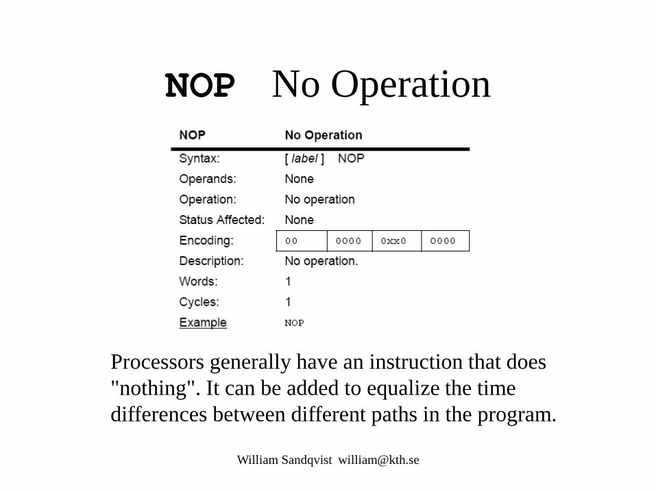
NOP No Operation
Processors generally have an instruction that does "nothing". It can be added to equalize the time differences between different paths in the program.

William Sandqvist [email protected]
How long time does instructions take? The processor internal clock uses ¼ of the oscillator frequency. Usual is 4 MHz crystal and then there will be 1 MHz clock speed. Most operations are performed in one clock cycle, ie, takes 1µs. The instructions that affect the PC takes two clock cycles, ie, 2 µs.
GOTO, CALL, RETURN Allways take 2 cycles,
DECFSZ, INCFZ, BTFSC, BTFSS takes 2 cykles when they create ”skip”, otherwise 1 cykle.
One can calculate the PIC processor execution time with finger counting!

William Sandqvist [email protected]
Ports
Of the PIC circuit pins 6 are bundled to a PORTA and 8 to a PORTC, 4 to a PORTB. The pins can also be used alone, and apparently they can have many optional features.
+ -

William Sandqvist [email protected]
Tris-register If a pin is to be used as input or output depends on settings in a TRIS-register.
TRISA and TRISB and TRISC
If the "corresponding" bit in trisregistret is 1 the pin is used as an input, if it’s 0 as an output!
TRIS = Threestate

William Sandqvist [email protected]

William Sandqvist [email protected]
An Assembly program init CLRF PORTB; MOVLW 10111111b; MOVWF TRISB; loop BTFSS PORTB,7; GOTO lampoff; lampon BSF PORTB,6; GOTO loop; lampoff BCF PORTB,6; GOTO loop; end;
The program lights on and off the LED on the command from the switch.
(This of course could be done without PIC - but then it's no sport!)

William Sandqvist [email protected]
Commented assembly program Assembly language program is called "spaghetti programming". It becomes easier to follow the program jumps when you draw out the arrows.
init CLRF PORTB; reset register portB MOVLW 10111111b; get a constant to the working register W MOVWF TRISB; copy the constant to trisB register loop BTFSS PORTB,7; skip next instruction if portb.7 = 1 GOTO lampoff; jump to ”lampoff” lampon BSF PORTB,6; Set portB.6 -> light up LED GOTO loop; go on from ”loop” lampoff BCF PORTB,6; reset portB.6 -> turn off LED GOTO loop; go on from ”loop” end;

William Sandqvist [email protected]
C-program /* onoff.c */ /* B Knudsen Cc5x */ /* C-compiler */ /* not ANSI-C */ #include "16F690.h " #pragma config |= 0x00D4 void main( void) { TRISB.6 = 0; PORTB.7 = 1; while(1) { if ( PORTB.7==1 ) PORTB.6=1; else PORTB.6=0; } }
Pragma – extensions of theC-language Bitvariables variabel.bit The compiler recognizes names of most registers, the rest of the names are stated in the processor include file.

William Sandqvist [email protected]
Download format The program code is downloaded to the chip with a circuit program-mer.
The format used is a text file with the op-codes as a string of Hex digits. This is the download code for the previous example program.
:1000000001288316031307108312071483120313A6 :10001000871C0C28071406288312031307100628D0 :02400E00D400DC :00000001FF End of file.
William Sandqvist [email protected]
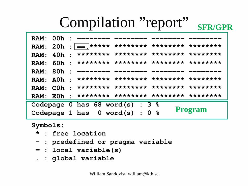
Compilation ”report” RAM: 00h : -------- -------- -------- -------- RAM: 20h : ==.***** ******** ******** ******** RAM: 40h : ******** ******** ******** ******** RAM: 60h : ******** ******** ******** ******** RAM: 80h : -------- -------- -------- -------- RAM: A0h : ******** ******** ******** ******** RAM: C0h : ******** ******** ******** ******** RAM: E0h : ******** ******** ******** ******** Codepage 0 has 68 word(s) : 3 % Codepage 1 has 0 word(s) : 0 %
Symbols: * : free location - : predefined or pragma variable = : local variable(s) . : global variable
Program
SFR/GPR

William Sandqvist [email protected]
( Cc5x internal variables )
char W; char INDF, TMR0, PCL, STATUS, FSR, PORTA, PORTB; char OPTION, TRISA, TRISB; /* STATUS : */ bit Carry, DC, Zero_, PD, TO, PA0, PA1, PA2; /* FSR : */ bit FSR_5, FSR_6; char PORTC, TRISC; char PCLATH, INTCON; /* OPTION : */ bit PS0, PS1, PS2, PSA, T0SE, T0CS, INTEDG, RBPU_; /* STATUS : */ bit Carry, DC, Zero_, PD, TO, RP0, RP1, IRP; /* INTCON : */ bit RBIF, INTF, T0IF, RBIE, INTE, T0IE, GIE;
Built-in the compiler provides the following names of registers and flags (bits in register):
These should not be declared in the programs. Include files then hold additional register names and names of bits, the same names that are used in the official manual.
William Sandqvist [email protected]
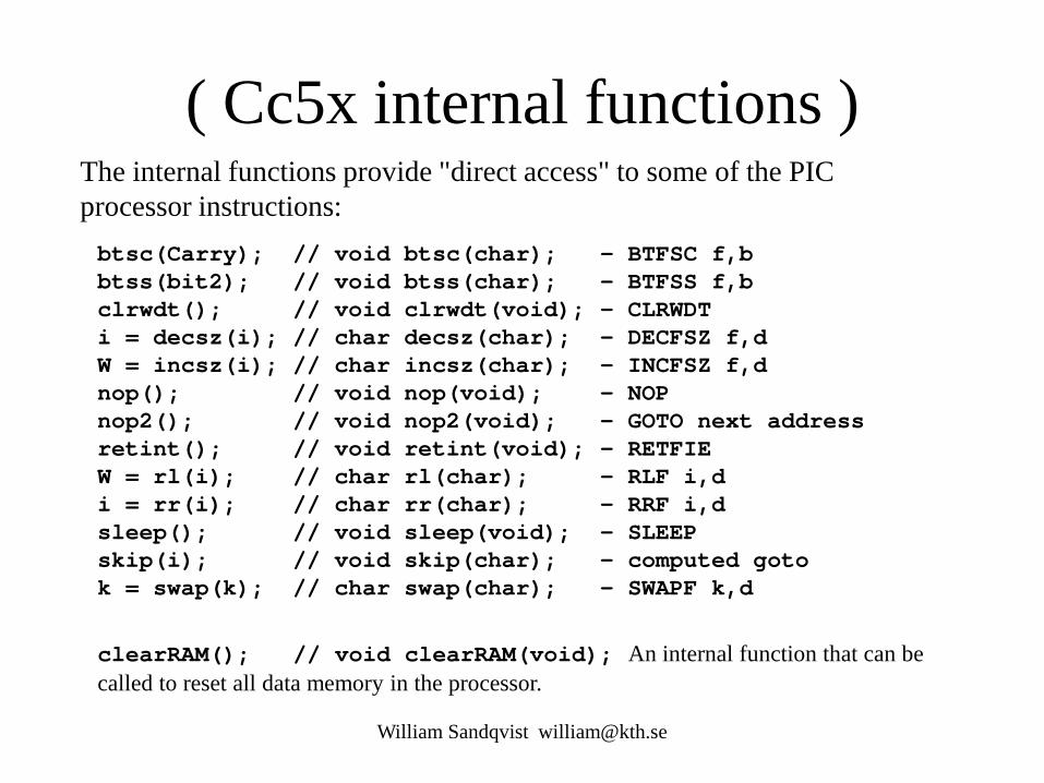
( Cc5x internal functions )
btsc(Carry); // void btsc(char); - BTFSC f,b btss(bit2); // void btss(char); - BTFSS f,b clrwdt(); // void clrwdt(void); - CLRWDT i = decsz(i); // char decsz(char); - DECFSZ f,d W = incsz(i); // char incsz(char); - INCFSZ f,d nop(); // void nop(void); - NOP nop2(); // void nop2(void); - GOTO next address retint(); // void retint(void); - RETFIE W = rl(i); // char rl(char); - RLF i,d i = rr(i); // char rr(char); - RRF i,d sleep(); // void sleep(void); - SLEEP skip(i); // void skip(char); - computed goto k = swap(k); // char swap(char); - SWAPF k,d
The internal functions provide "direct access" to some of the PIC processor instructions:
clearRAM(); // void clearRAM(void); An internal function that can be called to reset all data memory in the processor.

William Sandqvist [email protected]
(Simple C-statements → Assembler) Simple C statements are in general translated directly to the single assembler instructions. Programs written in assembly language can be translated instructions by instruction to a Cc5x C program.
A typical program
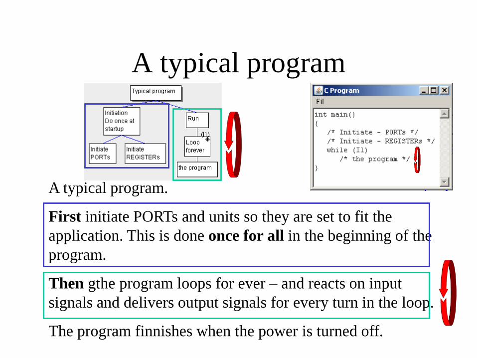
A typical program.
First initiate PORTs and units so they are set to fit the application. This is done once for all in the beginning of the program.
Then gthe program loops for ever – and reacts on input signals and delivers output signals for every turn in the loop.
The program finnishes when the power is turned off.
Single run program?
William Sandqvist [email protected]
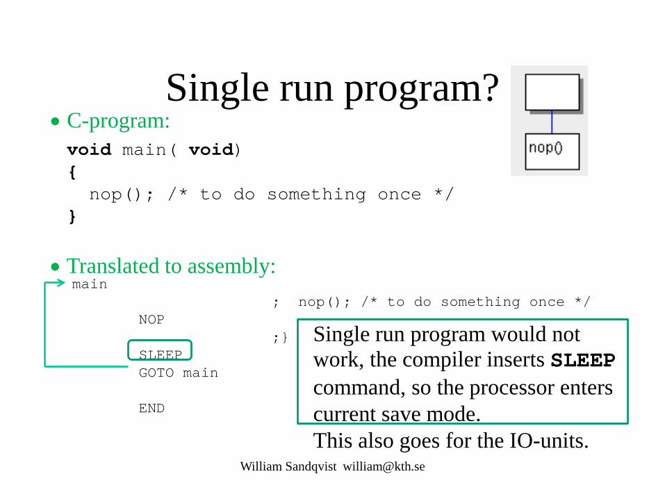
main ; nop(); /* to do something once */ NOP ;} SLEEP GOTO main END
void main( void) { nop(); /* to do something once */ }
Single run program would not work, the compiler inserts SLEEP command, so the processor enters current save mode. This also goes for the IO-units.
• C-program:
• Translated to assembly:

Single run program?
William Sandqvist [email protected]
main ; nop(); /* something once */ NOP ; while(1) ; m001 GOTO m001 END
void main( void) { nop(); /* something once */ while(1); }
This is a program that does not force the compiler to use SLEEP, the power saving mode.
• C-program:
• Translated to assembly:
Wait for a key press?
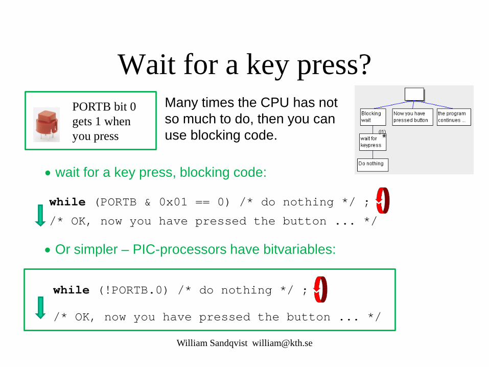
• wait for a key press, blocking code:
while (PORTB & 0x01 == 0) /* do nothing */ ;
PORTB bit 0 gets 1 when you press
• Or simpler – PIC-processors have bitvariables:
while (!PORTB.0) /* do nothing */ ;
Many times the CPU has not so much to do, then you can use blocking code.
/* OK, now you have pressed the button ... */
/* OK, now you have pressed the button ... */
William Sandqvist [email protected]

Contact bounces! When you press, or release, a mechanical contact it bounces a while before the contact surface is coming to rest. PIC processor are so fast that they can perceive each bounce as distinct contact press!
If a contact will bounce much or little is not visible on the outside!
? ≈3 ms
≈3 ms
William Sandqvist [email protected]
≈? ms

Toggle a LED ON/OFF
void main( void) { TRISB = 0b10111111; /* RB7 in, RB6 out */ while(1) { while( !PORTB.7 ) ; /* wait key pressed */ PORTB.6 = !PORTB.6; /* toggle led */ while( PORTB.7 ) ; /* wait for key released */ } }
Nothing else than a random number generator, anything can happen/not happen when you press the button!
William Sandqvist [email protected]
• Not as thought, every other time - but a random number generator!

Toggle a LED ON/OFF
void main( void) { TRISB = 0b10111111; /* RB7 in, RB6 out */ while(1) { while( !PORTB.7 ) ; /* wait key pressed */ PORTB.6 = !PORTB.6; /* toggle led */ delay(5); while( PORTB.7 ) ; /* wait for key released */ delay(5); } }
Wait out the contact bounces. A contact can bounce both when pressing it and when you release it!
Wait out the contact bounces (>5ms)
William Sandqvist [email protected]
• Now it works!
Wait out the contact bounces (>5ms)


C-functions void delay(char);
void main( void) { TRISB = 0b10111111; /* RB7 in, RB6 out */ while(1) { while( !PORTB.7 ) ; /* wait key pressed */ PORTB.6 = !PORTB.6; /* toggle led */ delay(5); while( PORTB.7 ) ; /* wait for key released */ delay(5); } }
• Function declaration (prototype) before main()
• Function call
• Function call
• Place the funktion definition after main() in the same file. William Sandqvist [email protected]

delay() function /* Delays a multiple of 1 milliseconds at 4 MHz */ /* (16F690 internal clock) using the TMR0 timer */
void delay( char millisec) { OPTION = 2; /* prescaler divide by 8 */ do { TMR0 = 0;
while ( TMR0 < 125) /* 125 * 8 = 1000 */ ; } while ( -- millisec > 0); }
1000 µs millisec Nr of turns
do { --- ; } while(---);
It is the after-tested loop that is the iteration procedure that best fits the PIC processor.
• Place function definitions after main() in the same file.
William Sandqvist [email protected]
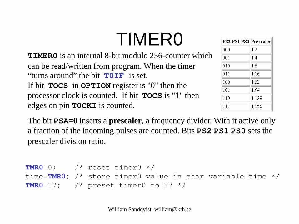
TIMER0 TIMER0 is an internal 8-bit modulo 256-counter which can be read/written from program. When the timer “turns around” the bit T0IF is set. If bit TOCS in OPTION register is "0" then the processor clock is counted. If bit TOCS is "1" then edges on pin T0CKI is counted.
The bit PSA=0 inserts a prescaler, a frequency divider. With it active only a fraction of the incoming pulses are counted. Bits PS2 PS1 PS0 sets the prescaler division ratio.
TMR0=0; /* reset timer0 */ time=TMR0; /* store timer0 value in char variable time */ TMR0=17; /* preset timer0 to 17 */
William Sandqvist [email protected]


C-functions summary
William Sandqvist [email protected]
• Function deklarations before main(). • Call from inside main()or from inside other functions. • Function definitions afterr main(), in the same file.
Often its so little code that everything can be in one file. The functions are often tailored directly to the application and the processor, therefore it may be unnecessary to store them as a ”general” function library.

Wait for key presses?
while(!PORTB.0 || !PORTB.1) /* do nothing */ ; /* now one or both buttons are pressed */ if(PORTB.0) /* action for red button */ ; if(PORTB.1) /* action for black button */ ;
Two keys, blocking code.
William Sandqvist [email protected]
PORTB bit 0 gets 1 when one presses the key
PORTB bit 1 gets 1 when one presses the key
OR

React on keypresses?
bit flagbit; While(1) /* main programloop */ { /* examine button status */ if(PORTB.0) /* direct action for red button */ ; if(PORTB.1) flagbit = 1; else flagbit = 0; /* . . . */ /* later, act on the flagbit */ if(flagbit) /* action for black button */ ; }
Two keys, nonblocking code
One can react directly on the key status or share the information with a bitvariabel, a flag bit.
William Sandqvist [email protected]
• Contact bounces?
PORTB bit 0 gets 1 when one presses the key
PORTB bit 1 gets 1 when one presses the key

bit flagbit; While(1) /* main programloop */ { /* examine button status */ if(PORTB.0) /* direct action for red button */ ; if(PORTB.1) flagbit = 1; else flagbit = 0; /* . . . */ /* later, act on the flagbit */ if(flagbit) /* action for black button */ ; delay(5); }
Wait out (>5ms) contact bounces before the nect turn in the main-loop
William Sandqvist [email protected]
React on keypresses?
Two keys, nonblocking code
PORTB bit 0 gets 1 when one presses the key
PORTB bit 1 gets 1 when one presses the key

Checkbox or Radiobutton? Checkbox (meny alternatives):
if(a)b; if(c)d; if(e)f; . . .
Radio Button (only one):
if(a)b; else if(c)d; ... else f;
William Sandqvist [email protected]
? ?

William Sandqvist [email protected]
Radiobutton … To select only one option among several …
if(a) b;
else if(c) d;
else f;
Or with the C-language switch-case expression …

C-language switch – case expression
William Sandqvist [email protected]
Hint! Note that B Knudsen compiler generates more effective code for • switch() – case than for • if() – else if() – else so always use a switch statement when possible!

William Sandqvist [email protected]
C switch – case switch(d) { case 0×00 : k='1'; break; case 0×01 : k='2'; break; case 0×02 : k='3'; break; case 0×04 : k='4'; break; case 0×05 : k='5'; break; case 0×06 : k='6'; break; case 0×08 : k='7'; break; case 0×09 : k='8'; break; case 0×0A : k='9'; break; case 0×0C : k='*'; break; case 0×0D : k='0'; break; case 0×0E : k='#'; break; /* 0×03,0×07,0×0B,0×0F */ default : k=' '; }
Recoding. Keyboard delivers mostly a completely different code d than is engraved on the key k !

William Sandqvist [email protected]
switch( choice ) { case 'Y' : /* Yes */ case 'y' : /* yes */ case 'J' : /* Ja */ case 'j' : /* ja */ printf( "As you wish" ); break; case 'N' : /* No Nej */ case 'n' : /* no nej */ printf( "Ok. You don't need to" ); break; default : printf("Wrong answer, Y/y/J/j/N/n"); }
Group alternatives
Default, for all unspecified alternatives
Handy menu-handling
William Sandqvist [email protected]
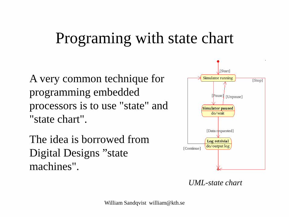
Programing with state chart
A very common technique for programming embedded processors is to use "state" and "state chart".
The idea is borrowed from Digital Designs ”state machines".
UML-state chart

William Sandqvist [email protected]
Multitask?
/* Blink1: 1s ON - 1s OFF */
/* Blink2: 0,2s ON - 0,2s OFF - 1s ON - 1s OFF */

William Sandqvist [email protected]
First one lightdiode … while(1) { /* Blink1: 1s ON - 1s OFF */ switch(State1) { case 0: PORTB_copy.6=1; /* Blink1 = ON */ Time1++; if( Time1 == 10 ) { State1 = 1; Time1 = 0; } break; case 1: PORTB_copy.6=0; /* Blink1 = OFF */ Time1++; if( Time1 == 10 ) { State1 = 0; Time1 = 0; } } PORTB = PORTB_copy; delay10(10); /* 0,1 sec delay each lap */ }

William Sandqvist [email protected]
Then another lightdiode … while(1) { /* Blink2: 0,2s ON - 0,2s OFF - 1s ON - 1s OFF */ switch(State2){ case 0: PORTB_copy.5 = 1; Time2++; /* Blink2 ON */ if( Time2 == 2 ) { State2 = 1; Time2 = 0; } break; case 1: PORTB_copy.5 = 0; Time2++; /* Blink2 OFF */ if( Time2 == 2 ) { State2 = 2; Time2 = 0; } break; case 2: PORTB_copy.5 = 1; Time2++; /* Blink2 ON */ if( Time2 == 10 ) { State2 = 3; Time2 = 0; } break; case 3: PORTB_copy.5 = 0; Time2++; /* Blink2 OFF */ if( Time2 == 10 ) { State2 = 0; Time2 = 0; } } PORTB=PORTB_copy: delay10(10); /* 0,1 sek delay */ }

William Sandqvist [email protected]
Why not both?
while(1) { /* Blink1: 1s ON - 1s OFF */ switch(State1) { case 0: ... ; break; case 1: ... ; } /* Blink2: 0,2s ON - 0,2s OFF - 1s ON - 1s OFF */ switch(State2) { case 0: ... ; break; case 1: ... ; break; case 2: ... ; break; case 3: ... ; } PORTB = PORTB_copy; delay10(10); /* 0,1 sek delay */ }
fast 10 µs
fast 10 µs
slow 0.1 s

William Sandqvist [email protected]
State machine
WARNING! There is a "sneaky" so-called RMW problem. HINT, SOLUTION: Changing bits in a variable PORT_copy instead of directly on the PORT. Then copy this entire variable to port, port = PORT_copy; More about this later in course …
By programming "state machines" (compare with Digital Design) you can make it look as if the processor is able to accomplish many things simultaneously. One can try out each thing separately, and usually works then the whole combination as intended.

William Sandqvist [email protected]