wi-1 winch - mudtoys - winch.pdf · wi-1 winch page mechanical winch wi-2 power take-off (p.t.o.)...
TRANSCRIPT
WI-1
WINCHPage
MECHANICAL WINCH WI-2Power Take-Off (P.T.O.) WI-2Drive Shaft WI-11Winch Assembly WI-14
ELECTRIC WINCH WI-25On-Vehicle Inspection WI-25Removal and Installation of Winch Assembly WI-27Winch Assembly WI-28Winch Components WI-33Winch Motor WI-44Magnet Switch No.1 WI-49Magnet Switch No.2 WI-51
WI-2 WINCH - Mechanical Winch (Power Take-Off)
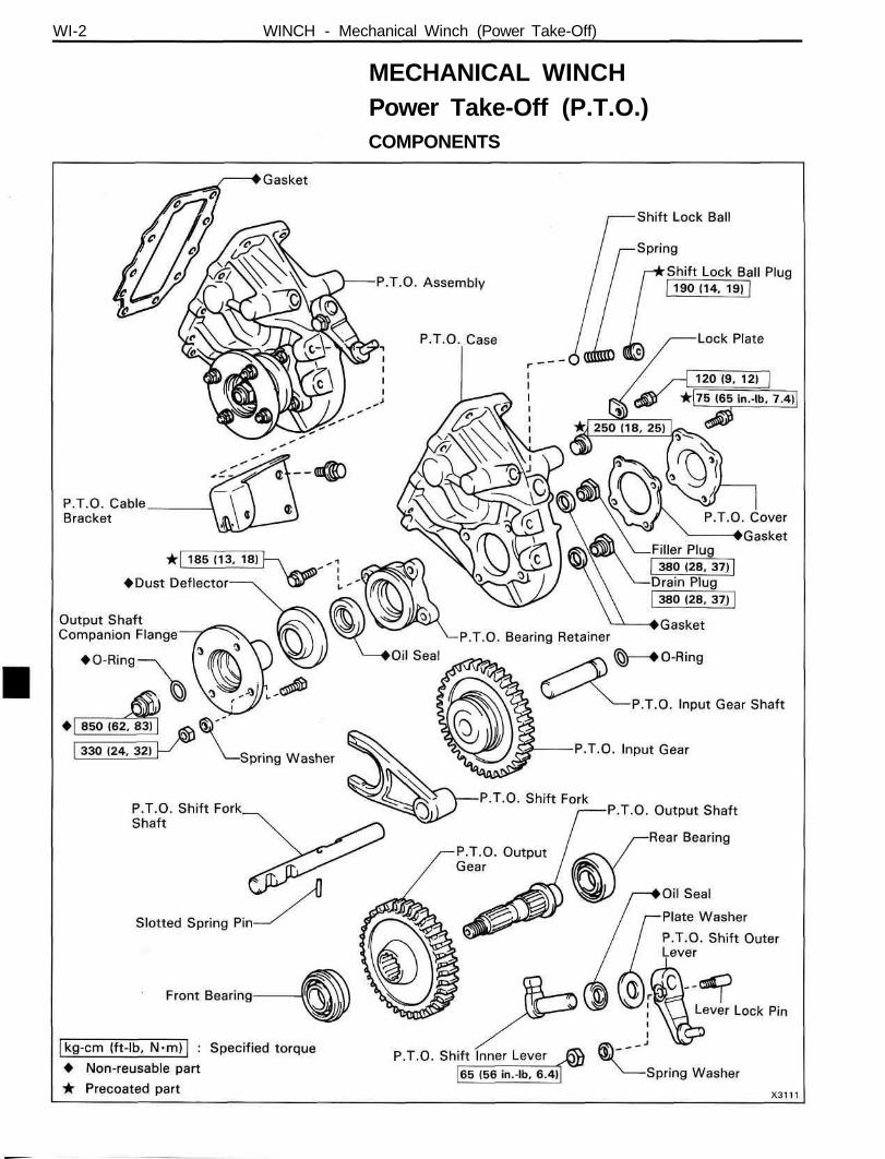
MECHANICAL WINCHPower Take-Off (P.T.O.)COMPONENTS
WINCH - Mechanical Winch (Power Take-Off) WI-3
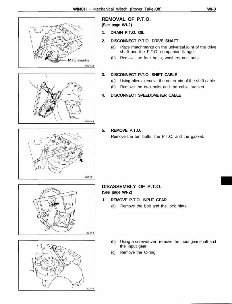
REMOVAL OF P.T.O.(See page WI-2)
1. DRAIN P.T.O. OIL
2. DISCONNECT P.T.O. DRIVE SHAFT(a) Place matchmarks on the universal joint of the drive
shaft and the P.T.O. companion flange.
(b) Remove the four bolts, washers and nuts.
3. DISCONNECT P.T.O. SHIFT CABLE(a) Using pliers, remove the cotter pin of the shift cable.
(b) Remove the two bolts and the cable bracket.
4. DISCONNECT SPEEDOMETER CABLE
5. REMOVE P.T.O.Remove the ten bolts, the P.T.O. and the gasket.
DISASSEMBLY OF P.T.O.(See page WI-2)
1. REMOVE P.T.O. INPUT GEAR(a) Remove the bolt and the lock plate.
(b) Using a screwdriver, remove the input gear shaft andthe input gear.
(c) Remove the O-ring.
WI-4 WINCH - Mechanical Winch (Power Take-Off)
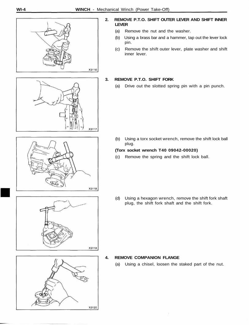
2. REMOVE P.T.O. SHIFT OUTER LEVER AND SHIFT INNERLEVER
(a) Remove the nut and the washer.
(b) Using a brass bar and a hammer, tap out the lever lockpin.
(c) Remove the shift outer lever, plate washer and shiftinner lever.
3. REMOVE P.T.O. SHIFT FORK
(a) Drive out the slotted spring pin with a pin punch.
(b) Using a torx socket wrench, remove the shift lock ballplug.
(Torx socket wrench T40 09042-00020)
(c) Remove the spring and the shift lock ball.
(d) Using a hexagon wrench, remove the shift fork shaftplug, the shift fork shaft and the shift fork.
4. REMOVE COMPANION FLANGE
(a) Using a chisel, loosen the staked part of the nut.
WINCH - Mechanical Winch (Power Take-Off) WI-5
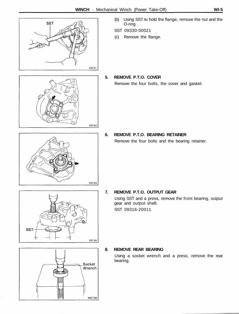
(b) Using SST to hold the flange, remove the nut and theO-ring.
SST 09330-00021
(c) Remove the flange.
5. REMOVE P.T.O. COVERRemove the four bolts, the cover and gasket.
6. REMOVE P.T.O. BEARING RETAINERRemove the four bolts and the bearing retainer.
7. REMOVE P.T.O. OUTPUT GEARUsing SST and a press, remove the front bearing, outputgear and output shaft.
SST 09316-20011
8. REMOVE REAR BEARINGUsing a socket wrench and a press, remove the rearbearing.
WI-6 WINCH - Mechanical Winch (Power Take-Off)
INSPECTION AND REPLACEMENT OF P.T.O.COMPONENTS
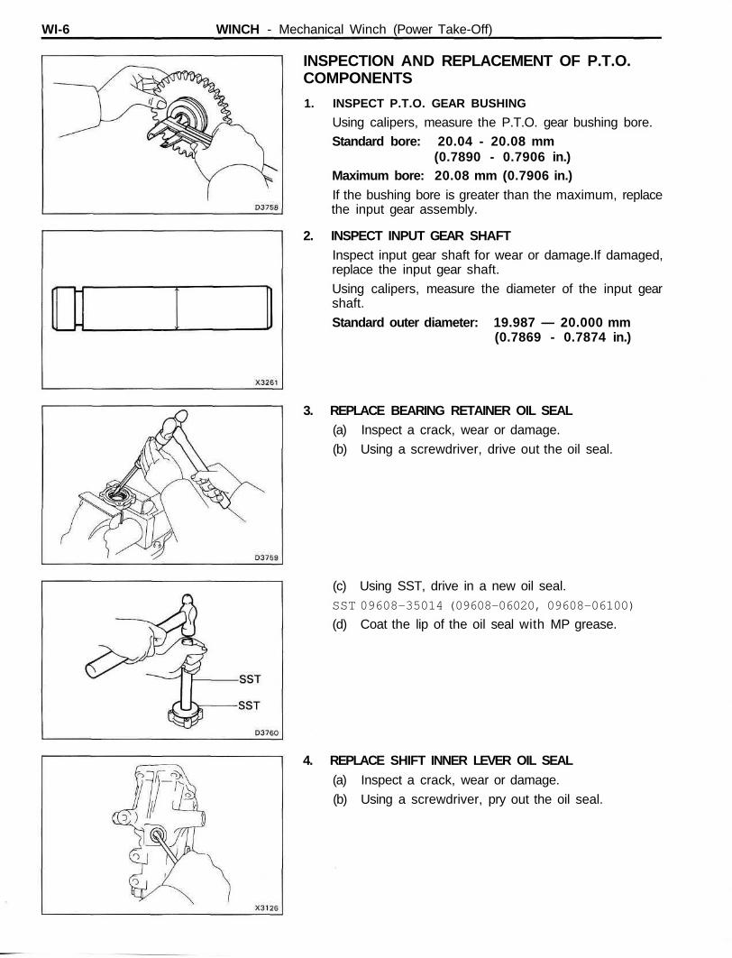
1. INSPECT P.T.O. GEAR BUSHING
Using calipers, measure the P.T.O. gear bushing bore.Standard bore: 20.04 - 20.08 mm
(0.7890 - 0.7906 in.)Maximum bore: 20.08 mm (0.7906 in.)If the bushing bore is greater than the maximum, replacethe input gear assembly.
2. INSPECT INPUT GEAR SHAFTInspect input gear shaft for wear or damage.If damaged,replace the input gear shaft.
Using calipers, measure the diameter of the input gearshaft.
Standard outer diameter: 19.987 — 20.000 mm(0.7869 - 0.7874 in.)
3. REPLACE BEARING RETAINER OIL SEAL(a) Inspect a crack, wear or damage.
(b) Using a screwdriver, drive out the oil seal.
(c) Using SST, drive in a new oil seal.SST 09608-35014 (09608-06020, 09608-06100)
(d) Coat the lip of the oil seal with MP grease.
4. REPLACE SHIFT INNER LEVER OIL SEAL(a) Inspect a crack, wear or damage.
(b) Using a screwdriver, pry out the oil seal.
WINCH - Mechanical Winch (Power Take-Off) WI-7
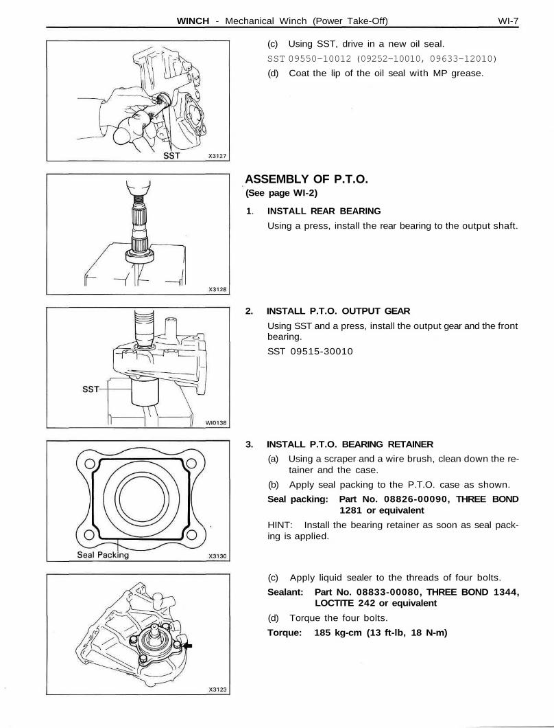
(c) Using SST, drive in a new oil seal.
SST 09550-10012 (09252-10010, 09633-12010)
(d) Coat the lip of the oil seal with MP grease.
ASSEMBLY OF P.T.O.(See page WI-2)
1. INSTALL REAR BEARING
Using a press, install the rear bearing to the output shaft.
2. INSTALL P.T.O. OUTPUT GEAR
Using SST and a press, install the output gear and the frontbearing.
SST 09515-30010
3. INSTALL P.T.O. BEARING RETAINER
(a) Using a scraper and a wire brush, clean down the re-tainer and the case.
(b) Apply seal packing to the P.T.O. case as shown.
Seal packing: Part No. 08826-00090, THREE BOND1281 or equivalent
HINT: Install the bearing retainer as soon as seal pack-ing is applied.
(c) Apply liquid sealer to the threads of four bolts.
Sealant: Part No. 08833-00080, THREE BOND 1344,LOCTITE 242 or equivalent
(d) Torque the four bolts.
Torque: 185 kg-cm (13 ft-lb, 18 N-m)
WI-8 WINCH - Mechanical Winch (Power Take-Off)
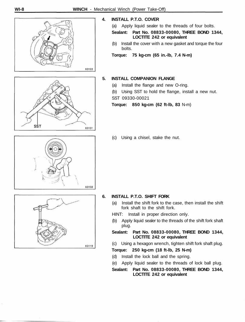
4. INSTALL P.T.O. COVER(a) Apply liquid sealer to the threads of four bolts.
Sealant: Part No. 08833-00080, THREE BOND 1344,LOCTITE 242 or equivalent
(b) Install the cover with a new gasket and torque the fourbolts.
Torque: 75 kg-cm (65 in.-lb, 7.4 N-m)
5. INSTALL COMPANION FLANGE(a) Install the flange and new O-ring.
(b) Using SST to hold the flange, install a new nut.
SST 09330-00021
Torque: 850 kg-cm (62 ft-lb, 83 N-m)
(c) Using a chisel, stake the nut.
6. INSTALL P.T.O. SHIFT FORK(a) Install the shift fork to the case, then install the shift
fork shaft to the shift fork.
HINT: Install in proper direction only.(b) Apply liquid sealer to the threads of the shift fork shaft
plug.
Sealant: Part No. 08833-00080, THREE BOND 1344,LOCTITE 242 or equivalent
(c) Using a hexagon wrench, tighten shift fork shaft plug.
Torque: 250 kg-cm (18 ft-lb, 25 N-m)(d) Install the lock ball and the spring.
(e) Apply liquid sealer to the threads of lock ball plug.
Sealant: Part No. 08833-00080, THREE BOND 1344,LOCTITE 242 or equivalent
WINCH - Mechanical Winch (Power Take-Off) WI-9
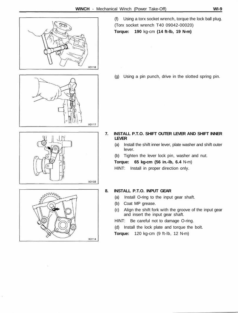
(f) Using a torx socket wrench, torque the lock ball plug.
(Torx socket wrench T40 09042-00020)
Torque: 190 kg-cm (14 ft-lb, 19 N-m)
(g) Using a pin punch, drive in the slotted spring pin.
7. INSTALL P.T.O. SHIFT OUTER LEVER AND SHIFT INNERLEVER(a) Install the shift inner lever, plate washer and shift outer
lever.(b) Tighten the lever lock pin, washer and nut.
Torque: 65 kg-cm (56 in.-lb, 6.4 N-m)
HINT: Install in proper direction only.
8. INSTALL P.T.O. INPUT GEAR(a) Install O-ring to the input gear shaft.
(b) Coat MP grease.
(c) Align the shift fork with the groove of the input gearand insert the input gear shaft.
HINT: Be careful not to damage O-ring.
(d) Install the lock plate and torque the bolt.
Torque: 120 kg-cm (9 ft-lb, 12 N-m)
WI-10 WINCH - Mechanical Winch (Power Take-Off)
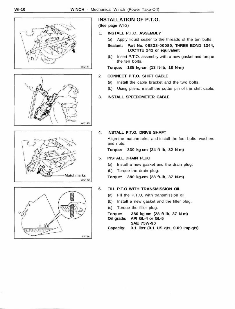
INSTALLATION OF P.T.O.(See page WI-2)
1. INSTALL P.T.O. ASSEMBLY
(a) Apply liquid sealer to the threads of the ten bolts.
Sealant: Part No. 08833-00080, THREE BOND 1344,LOCTITE 242 or equivalent
(b) Insert P.T.O. assembly with a new gasket and torquethe ten bolts.
Torque: 185 kg-cm (13 ft-lb, 18 N-m)
2. CONNECT P.T.O. SHIFT CABLE
(a) Install the cable bracket and the two bolts.
(b) Using pliers, install the cotter pin of the shift cable.
3. INSTALL SPEEDOMETER CABLE
4. INSTALL P.T.O. DRIVE SHAFT
Align the matchmarks, and install the four bolts, washersand nuts.
Torque: 330 kg-cm (24 ft-lb, 32 N-m)
5. INSTALL DRAIN PLUG
(a) Install a new gasket and the drain plug.
(b) Torque the drain plug.
Torque: 380 kg-cm (28 ft-lb, 37 N-m)
6. FILL P.T.O WITH TRANSMISSION OIL
(a) Fill the P.T.O. with transmission oil.
(b) Install a new gasket and the filler plug.
(c) Torque the filler plug.
Torque: 380 kg-cm (28 ft-lb, 37 N-m)Oil grade: API GL-4 or GL-5
SAE 75W-90Capacity: 0.1 liter (0.1 US qts, 0.09 Imp.qts)
WINCH - Mechanical Winch (Drive Shaft) WI-11
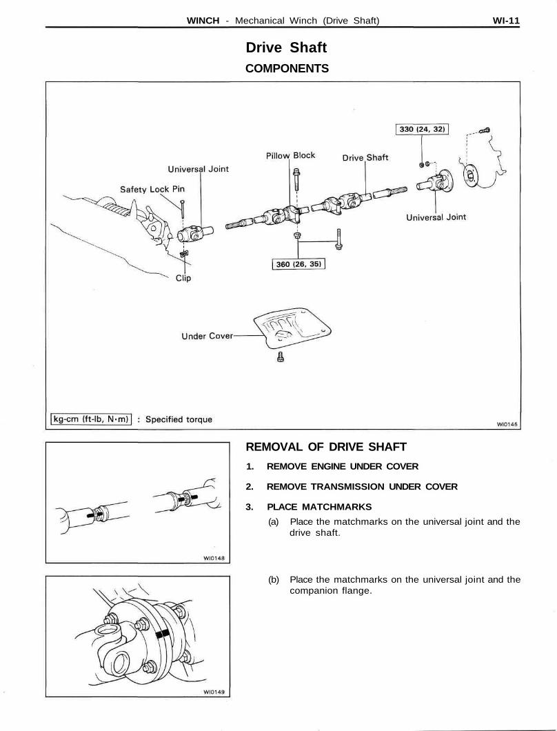
Drive ShaftCOMPONENTS
REMOVAL OF DRIVE SHAFT
1. REMOVE ENGINE UNDER COVER
2. REMOVE TRANSMISSION UNDER COVER
3. PLACE MATCHMARKS
(a) Place the matchmarks on the universal joint and thedrive shaft.
(b) Place the matchmarks on the universal joint and thecompanion flange.
WI-12 WINCH - Mechanical Winch (Drive Shaft)
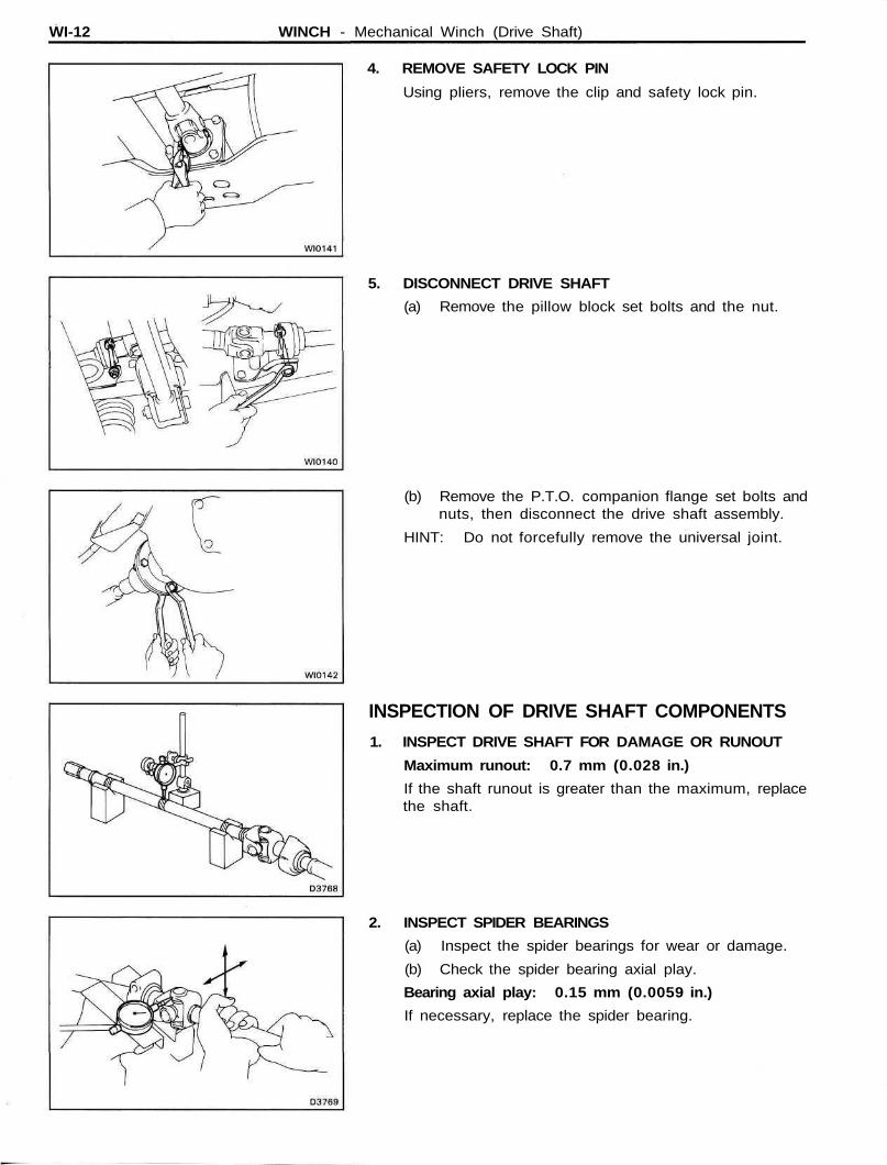
4. REMOVE SAFETY LOCK PIN
Using pliers, remove the clip and safety lock pin.
5. DISCONNECT DRIVE SHAFT
(a) Remove the pillow block set bolts and the nut.
(b) Remove the P.T.O. companion flange set bolts andnuts, then disconnect the drive shaft assembly.
HINT: Do not forcefully remove the universal joint.
INSPECTION OF DRIVE SHAFT COMPONENTS
1. INSPECT DRIVE SHAFT FOR DAMAGE OR RUNOUT
Maximum runout: 0.7 mm (0.028 in.)
If the shaft runout is greater than the maximum, replacethe shaft.
2. INSPECT SPIDER BEARINGS
(a) Inspect the spider bearings for wear or damage.
(b) Check the spider bearing axial play.
Bearing axial play: 0.15 mm (0.0059 in.)
If necessary, replace the spider bearing.
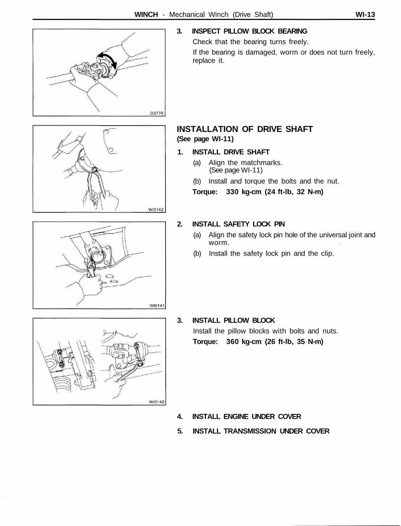
WINCH - Mechanical Winch (Drive Shaft) WI-13
3. INSPECT PILLOW BLOCK BEARINGCheck that the bearing turns freely.If the bearing is damaged, worm or does not turn freely,replace it.
INSTALLATION OF DRIVE SHAFT(See page WI-11)
1. INSTALL DRIVE SHAFT(a) Align the matchmarks.
(See page WI-11)
(b) Install and torque the bolts and the nut.
Torque: 330 kg-cm (24 ft-lb, 32 N-m)
2. INSTALL SAFETY LOCK PIN(a) Align the safety lock pin hole of the universal joint and
worm.
(b) Install the safety lock pin and the clip.
3. INSTALL PILLOW BLOCKInstall the pillow blocks with bolts and nuts.
Torque: 360 kg-cm (26 ft-lb, 35 N-m)
4. INSTALL ENGINE UNDER COVER
5. INSTALL TRANSMISSION UNDER COVER
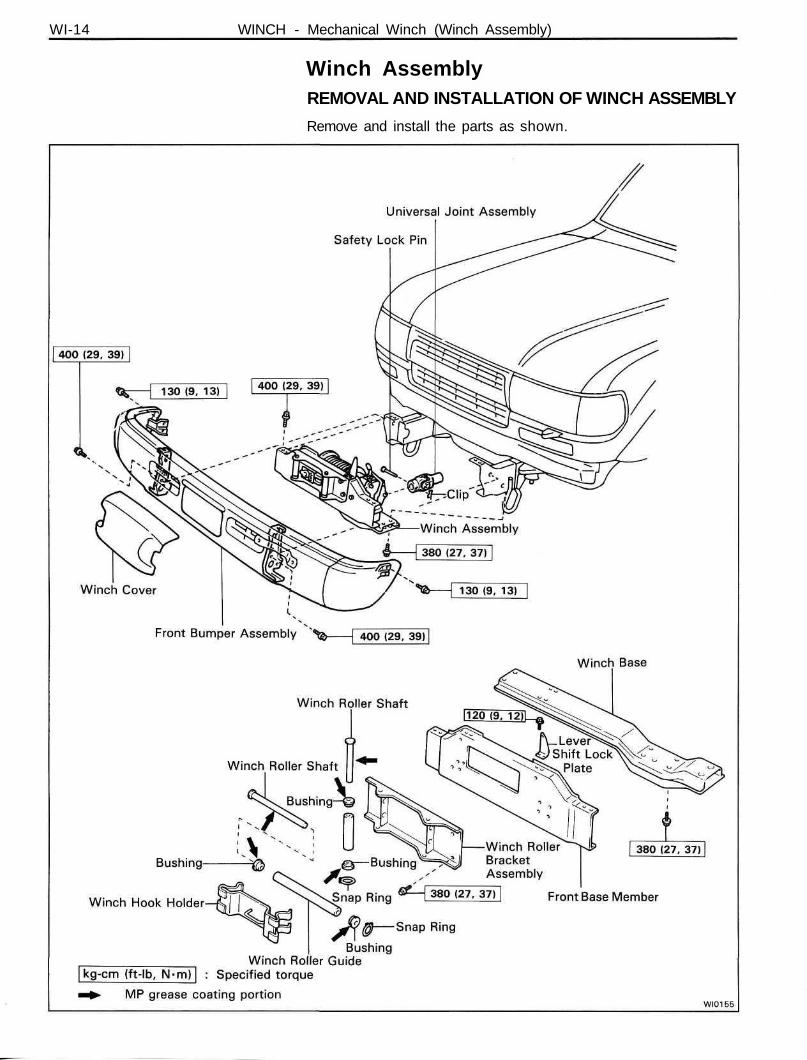
WI-14 WINCH - Mechanical Winch (Winch Assembly)
Winch AssemblyREMOVAL AND INSTALLATION OF WINCH ASSEMBLY
Remove and install the parts as shown.
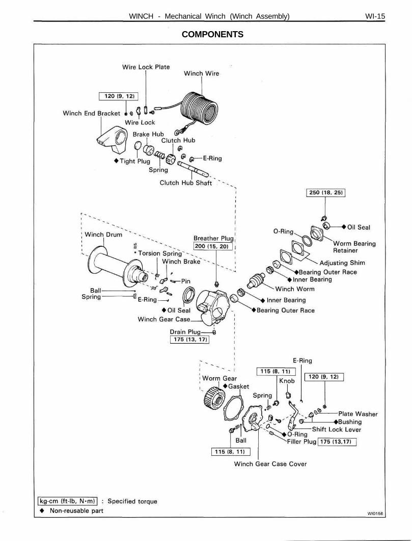
WINCH - Mechanical Winch (Winch Assembly) WI-15
COMPONENTS
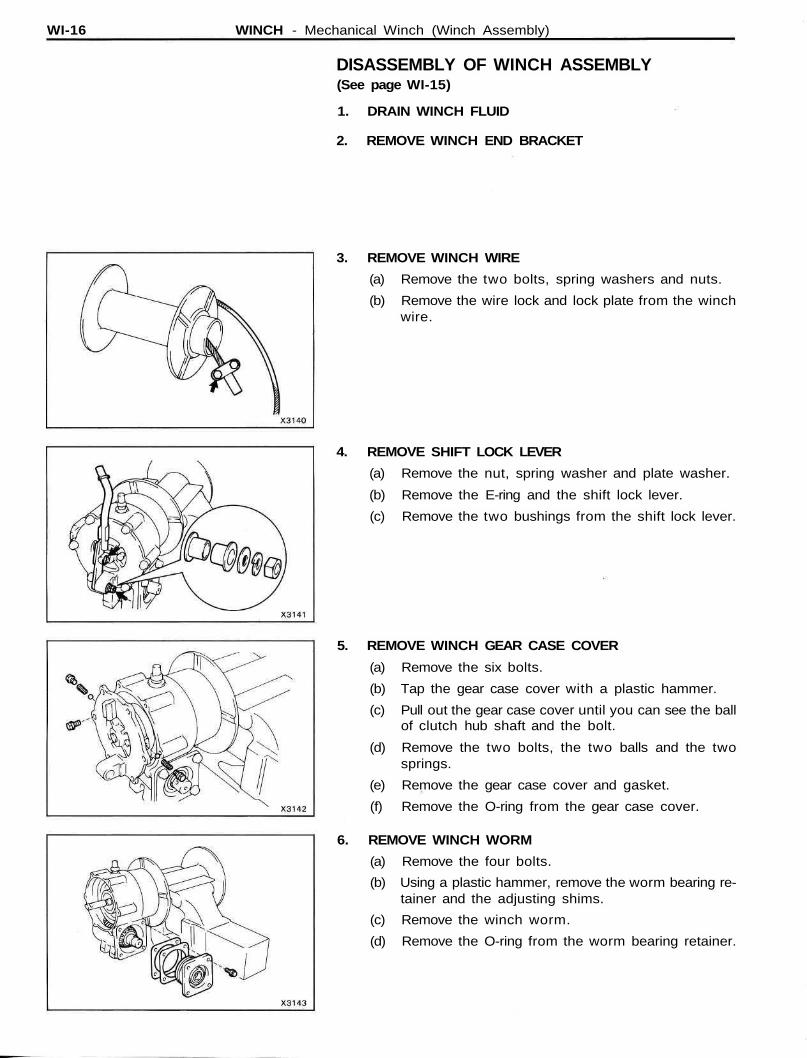
WI-16 WINCH - Mechanical Winch (Winch Assembly)
DISASSEMBLY OF WINCH ASSEMBLY(See page WI-15)
1. DRAIN WINCH FLUID
2. REMOVE WINCH END BRACKET
3. REMOVE WINCH WIRE
(a) Remove the two bolts, spring washers and nuts.
(b) Remove the wire lock and lock plate from the winchwire.
4. REMOVE SHIFT LOCK LEVER
(a) Remove the nut, spring washer and plate washer.
(b) Remove the E-ring and the shift lock lever.
(c) Remove the two bushings from the shift lock lever.
5. REMOVE WINCH GEAR CASE COVER
(a) Remove the six bolts.
(b) Tap the gear case cover with a plastic hammer.
(c) Pull out the gear case cover until you can see the ballof clutch hub shaft and the bolt.
(d) Remove the two bolts, the two balls and the twosprings.
(e) Remove the gear case cover and gasket.
(f) Remove the O-ring from the gear case cover.
6. REMOVE WINCH WORM
(a) Remove the four bolts.
(b) Using a plastic hammer, remove the worm bearing re-tainer and the adjusting shims.
(c) Remove the winch worm.
(d) Remove the O-ring from the worm bearing retainer.
WINCH - Mechanical Winch (Winch Assembly) WI-17
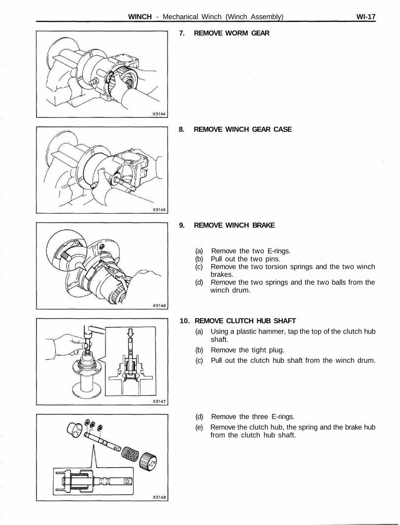
7. REMOVE WORM GEAR
8. REMOVE WINCH GEAR CASE
9. REMOVE WINCH BRAKE
(a) Remove the two E-rings.(b) Pull out the two pins.(c) Remove the two torsion springs and the two winch
brakes.(d) Remove the two springs and the two balls from the
winch drum.
10. REMOVE CLUTCH HUB SHAFT(a) Using a plastic hammer, tap the top of the clutch hub
shaft.
(b) Remove the tight plug.(c) Pull out the clutch hub shaft from the winch drum.
(d) Remove the three E-rings.
(e) Remove the clutch hub, the spring and the brake hubfrom the clutch hub shaft.
WI-18 WINCH - Mechanical Winch (Winch Assembly)
INSPECTION AND REPLACEMENT OF WINCHASSEMBLY
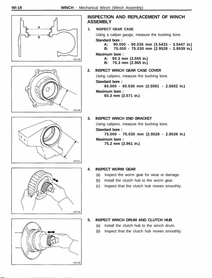
1. INSPECT GEAR CASE
Using a caliper gauge, measure the bushing bore.Standard bore :
A: 90.000 - 90.035 mm (3.5433 - 3.5447 in.)B: 75.000 - 75.030 mm (2.9528 - 2.9539 in.)
Maximum bore :A: 90.3 mm (3.555 in.)B: 75.3 mm (2.965 in.)
2. INSPECT WINCH GEAR CASE COVERUsing calipers, measure the bushing bore.
Standard bore :65.000 - 65.030 mm (2.5591 - 2.5602 in.)
Maximum bore :65.3 mm (2.571 in.)
3. INSPECT WINCH END BRACKETUsing calipers, measure the bushing bore.
Standard bore :75.000 - 75.030 mm (2.9528 - 2.9539 in.)
Maximum bore :75.2 mm (2.961 in.)
4. INSPECT WORM GEAR(a) Inspect the worm gear for wear or damage.
(b) Install the clutch hub to the worm gear.
(c) Inspect that the clutch hub moves smoothly.
5. INSPECT WINCH DRUM AND CLUTCH HUB(a) Install the clutch hub to the winch drum.
(b) Inspect that the clutch hub moves smoothly.
WINCH - Mechanical Winch (Winch Assembly) WI-19
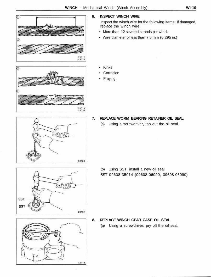
6. INSPECT WINCH WIREInspect the winch wire for the following items. If damaged,replace the winch wire.
• More than 12 severed strands per wind.
• Wire diameter of less than 7.5 mm (0.295 in.)
• Kinks• Corrosion
• Fraying
7. REPLACE WORM BEARING RETAINER OIL SEAL(a) Using a screwdriver, tap out the oil seal.
(b) Using SST, install a new oil seal.SST 09608-35014 (09608-06020, 09608-06090)
8. REPLACE WINCH GEAR CASE OIL SEAL(a) Using a screwdriver, pry off the oil seal.
WI-20 WINCH - Mechanical Winch (Winch Assembly)
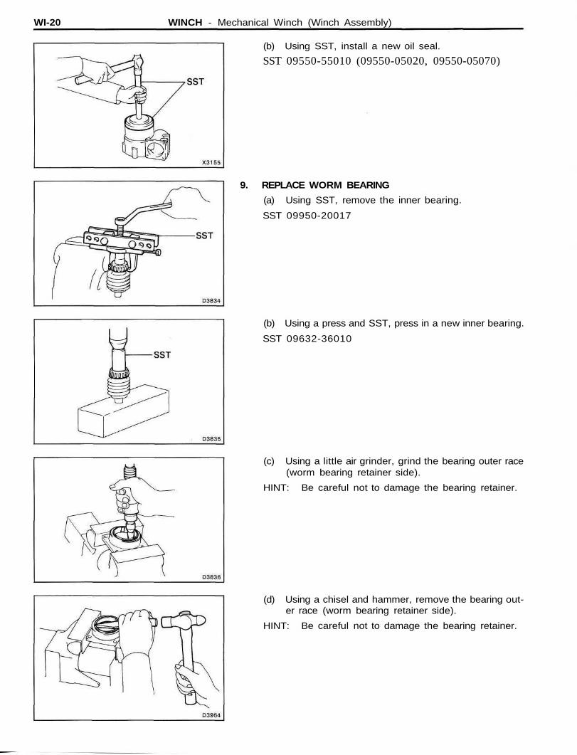
(b) Using SST, install a new oil seal.
SST 09550-55010 (09550-05020, 09550-05070)
9. REPLACE WORM BEARING
(a) Using SST, remove the inner bearing.
SST 09950-20017
(b) Using a press and SST, press in a new inner bearing.
SST 09632-36010
(c) Using a little air grinder, grind the bearing outer race(worm bearing retainer side).
HINT: Be careful not to damage the bearing retainer.
(d) Using a chisel and hammer, remove the bearing out-er race (worm bearing retainer side).
HINT: Be careful not to damage the bearing retainer.
WINCH - Mechanical Winch (Winch Assembly) WI-21
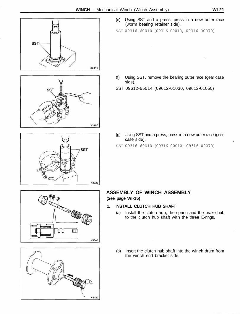
(e) Using SST and a press, press in a new outer race(worm bearing retainer side).
SST 09316-60010 (09316-00010, 09316-00070)
(f) Using SST, remove the bearing outer race (gear caseside).
SST 09612-65014 (09612-01030, 09612-01050)
(g) Using SST and a press, press in a new outer race (gearcase side).
SST 09316-60010 (09316-00010, 09316-00070)
ASSEMBLY OF WINCH ASSEMBLY(See page WI-15)
1. INSTALL CLUTCH HUB SHAFT(a) Install the clutch hub, the spring and the brake hub
to the clutch hub shaft with the three E-rings.
(b) Insert the clutch hub shaft into the winch drum fromthe winch end bracket side.
WI-22 WINCH - Mechanical Winch (Winch Assembly)
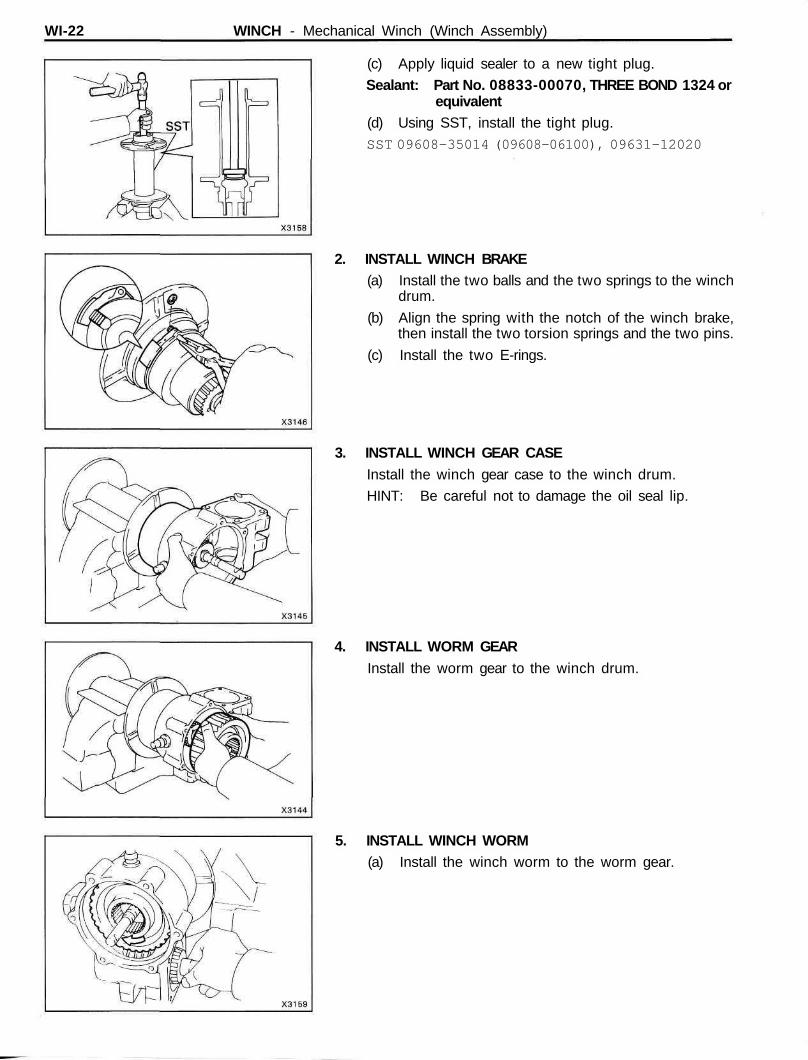
(c) Apply liquid sealer to a new tight plug.
Sealant: Part No. 08833-00070, THREE BOND 1324 orequivalent
(d) Using SST, install the tight plug.SST 09608-35014 (09608-06100), 09631-12020
2. INSTALL WINCH BRAKE(a) Install the two balls and the two springs to the winch
drum.
(b) Align the spring with the notch of the winch brake,then install the two torsion springs and the two pins.
(c) Install the two E-rings.
3. INSTALL WINCH GEAR CASEInstall the winch gear case to the winch drum.
HINT: Be careful not to damage the oil seal lip.
4. INSTALL WORM GEARInstall the worm gear to the winch drum.
5. INSTALL WINCH WORM(a) Install the winch worm to the worm gear.
WINCH - Mechanical Winch (Winch Assembly) WI-23
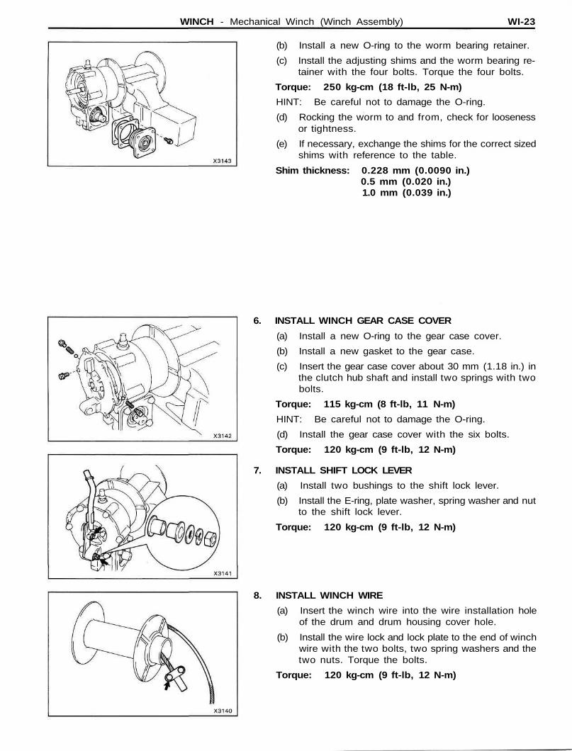
(b) Install a new O-ring to the worm bearing retainer.
(c) Install the adjusting shims and the worm bearing re-tainer with the four bolts. Torque the four bolts.
Torque: 250 kg-cm (18 ft-lb, 25 N-m)
HINT: Be careful not to damage the O-ring.
(d) Rocking the worm to and from, check for loosenessor tightness.
(e) If necessary, exchange the shims for the correct sizedshims with reference to the table.
Shim thickness: 0.228 mm (0.0090 in.)0.5 mm (0.020 in.)1.0 mm (0.039 in.)
6. INSTALL WINCH GEAR CASE COVER
(a) Install a new O-ring to the gear case cover.
(b) Install a new gasket to the gear case.
(c) Insert the gear case cover about 30 mm (1.18 in.) inthe clutch hub shaft and install two springs with twobolts.
Torque: 115 kg-cm (8 ft-lb, 11 N-m)
HINT: Be careful not to damage the O-ring.
(d) Install the gear case cover with the six bolts.
Torque: 120 kg-cm (9 ft-lb, 12 N-m)
7. INSTALL SHIFT LOCK LEVER
(a) Install two bushings to the shift lock lever.
(b) Install the E-ring, plate washer, spring washer and nutto the shift lock lever.
Torque: 120 kg-cm (9 ft-lb, 12 N-m)
8. INSTALL WINCH WIRE
(a) Insert the winch wire into the wire installation holeof the drum and drum housing cover hole.
(b) Install the wire lock and lock plate to the end of winchwire with the two bolts, two spring washers and thetwo nuts. Torque the bolts.
Torque: 120 kg-cm (9 ft-lb, 12 N-m)
WI-24 WINCH - Mechanical Winch (Winch Assembly)
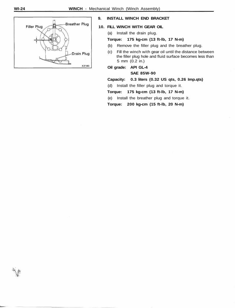
9. INSTALL WINCH END BRACKET
10. FILL WINCH WITH GEAR OIL
(a) Install the drain plug.
Torque: 175 kg-cm (13 ft-lb, 17 N-m)
(b) Remove the filler plug and the breather plug.
(c) Fill the winch with gear oil until the distance betweenthe filler plug hole and fluid surface becomes less than5 mm (0.2 in.)
Oil grade: API GL-4
SAE 85W-90
Capacity: 0.3 liters (0.32 US qts, 0.26 Imp.qts)
(d) Install the filler plug and torque it.
Torque: 175 kg-cm (13 ft-lb, 17 N-m)
(e) Install the breather plug and torque it.
Torque: 200 kg-cm (15 ft-lb, 20 N-m)
WINCH - Electric Winch (On-Vehicle Inspection) WI-25
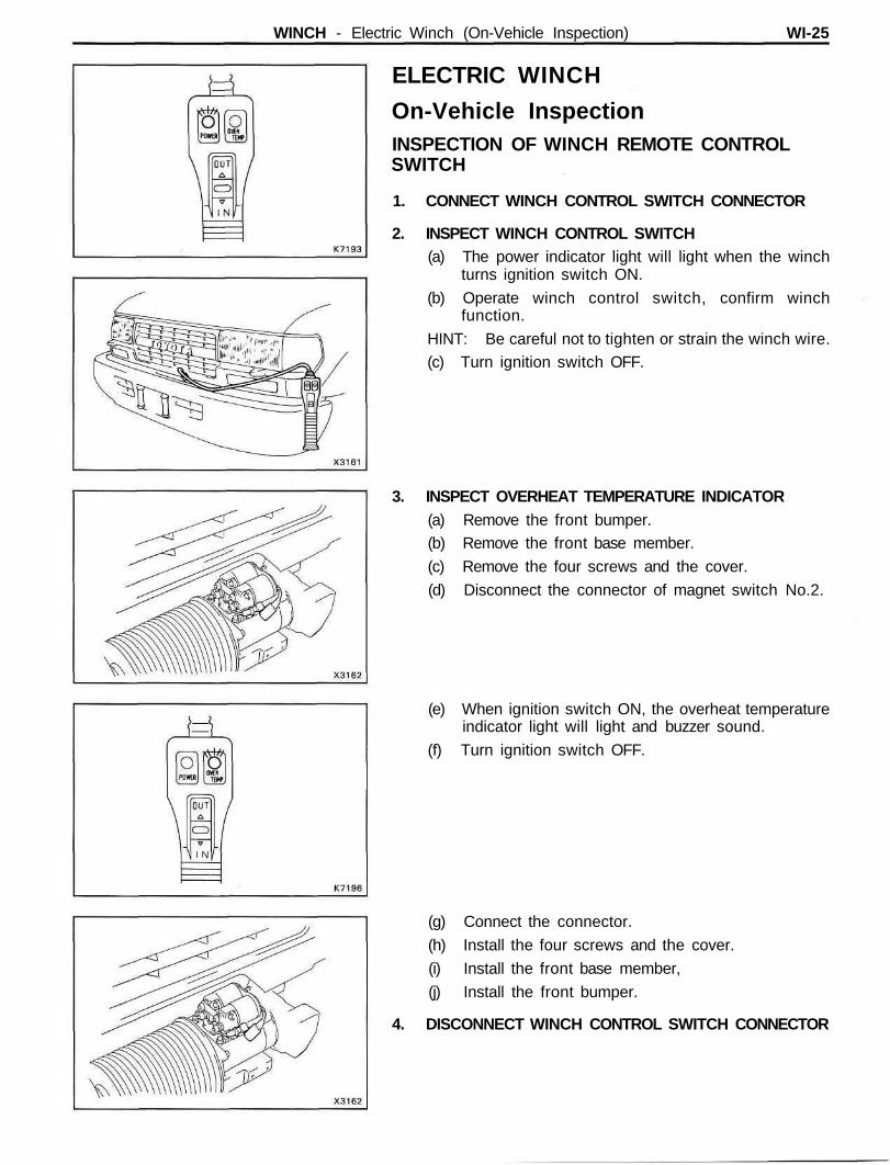
ELECTRIC WINCH
On-Vehicle InspectionINSPECTION OF WINCH REMOTE CONTROLSWITCH
1. CONNECT WINCH CONTROL SWITCH CONNECTOR
2. INSPECT WINCH CONTROL SWITCH(a) The power indicator light will light when the winch
turns ignition switch ON.
(b) Operate winch control switch, confirm winchfunction.
HINT: Be careful not to tighten or strain the winch wire.(c) Turn ignition switch OFF.
3. INSPECT OVERHEAT TEMPERATURE INDICATOR(a) Remove the front bumper.(b) Remove the front base member.
(c) Remove the four screws and the cover.
(d) Disconnect the connector of magnet switch No.2.
(e) When ignition switch ON, the overheat temperatureindicator light will light and buzzer sound.
(f) Turn ignition switch OFF.
(g) Connect the connector.
(h) Install the four screws and the cover.
(i) Install the front base member,
(j) Install the front bumper.
4. DISCONNECT WINCH CONTROL SWITCH CONNECTOR
WI-26 WINCH - Electric Winch (On-Vehicle Inspection)
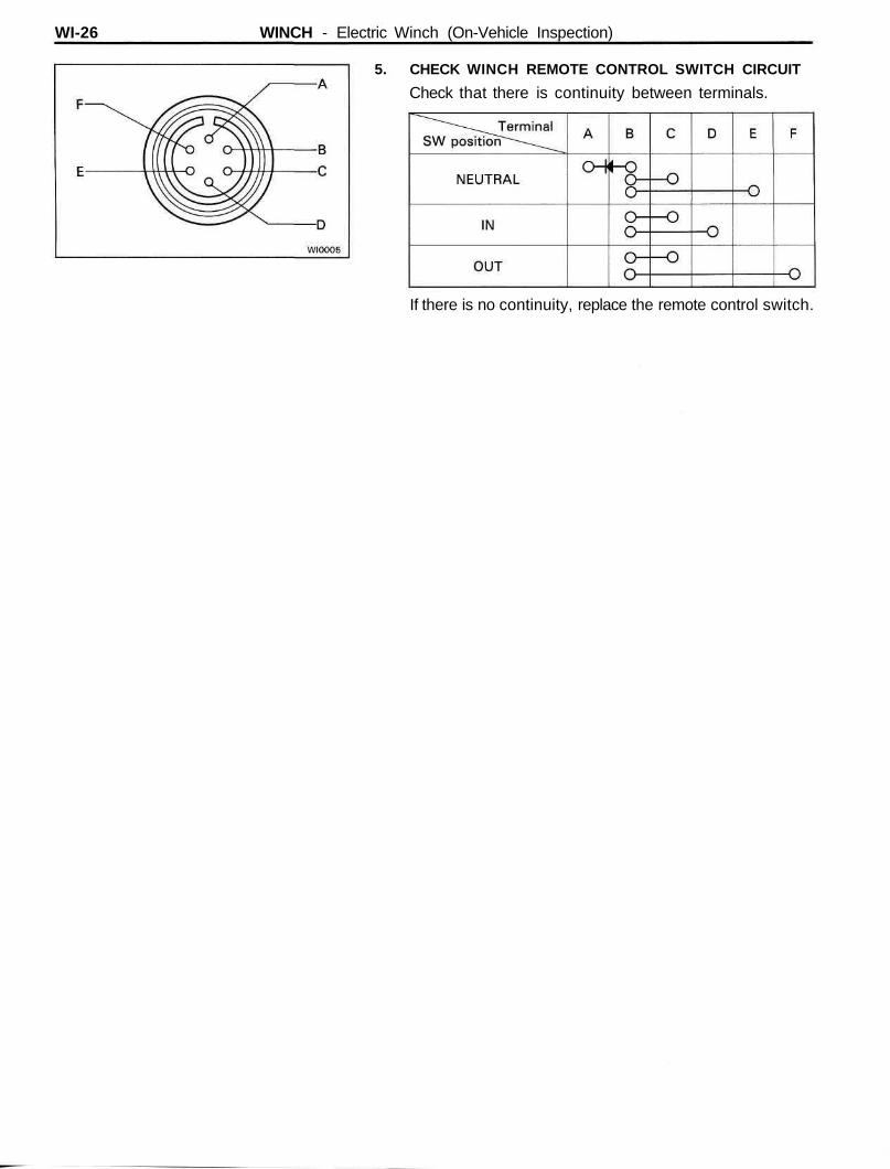
5. CHECK WINCH REMOTE CONTROL SWITCH CIRCUIT
Check that there is continuity between terminals.
If there is no continuity, replace the remote control switch.
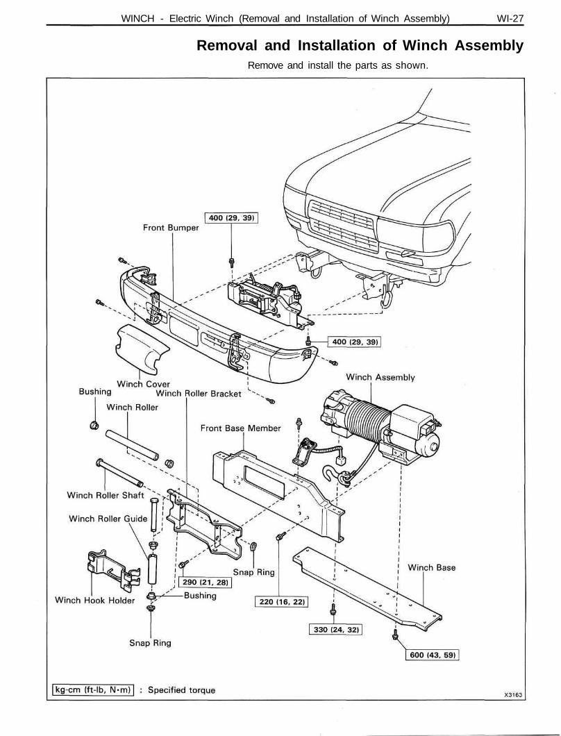
WINCH - Electric Winch (Removal and Installation of Winch Assembly) WI-27
Removal and Installation of Winch AssemblyRemove and install the parts as shown.
WI-28 WINCH - Electric Winch (Winch Assembly)
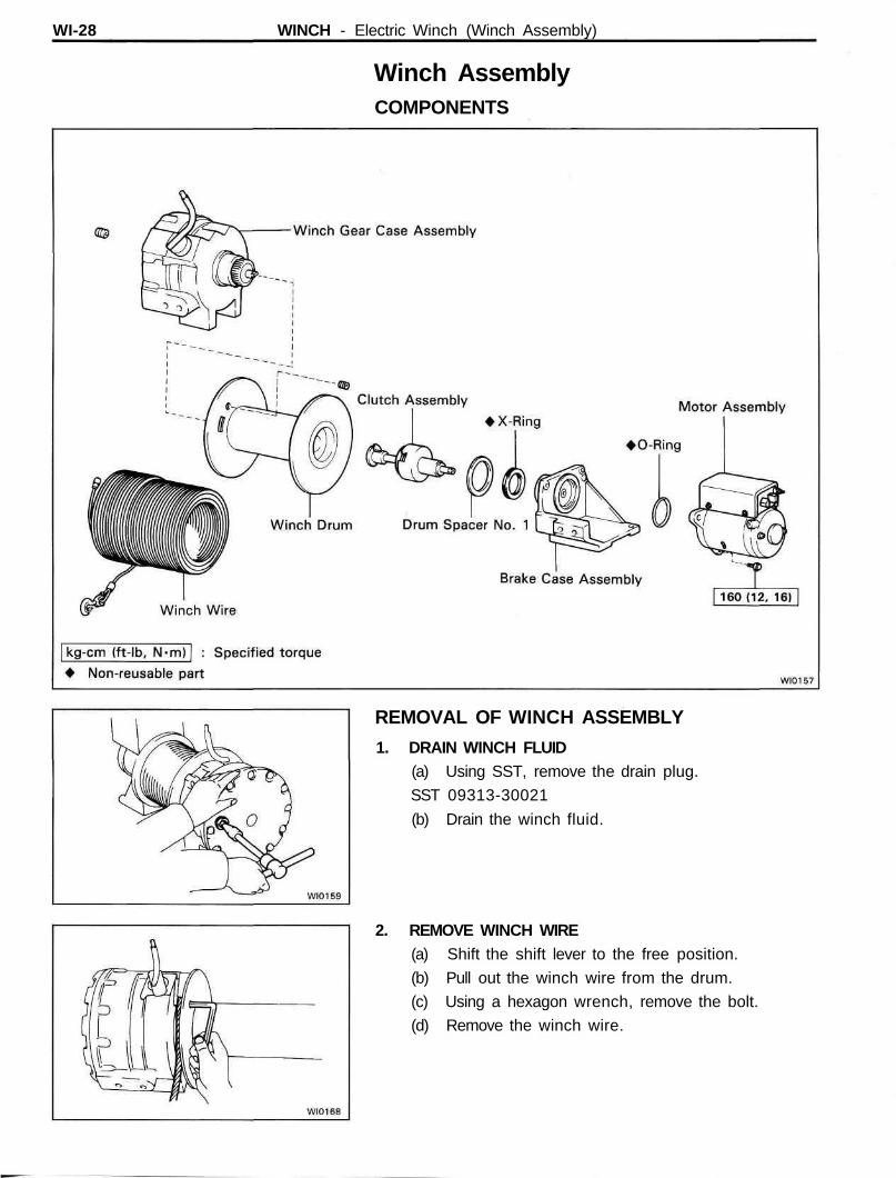
Winch AssemblyCOMPONENTS
REMOVAL OF WINCH ASSEMBLY
1. DRAIN WINCH FLUID(a) Using SST, remove the drain plug.
SST 09313-30021
(b) Drain the winch fluid.
2. REMOVE WINCH WIRE(a) Shift the shift lever to the free position.
(b) Pull out the winch wire from the drum.
(c) Using a hexagon wrench, remove the bolt.
(d) Remove the winch wire.
WINCH - Electric Winch (Winch Assembly) WI-29
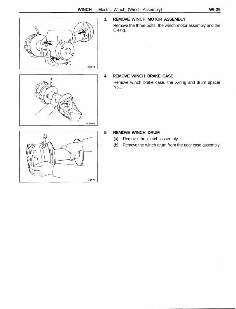
3. REMOVE WINCH MOTOR ASSEMBLYRemove the three bolts, the winch motor assembly and theO-ring.
4. REMOVE WINCH BRAKE CASERemove winch brake case, the X-ring and drum spacerNo.1.
5. REMOVE WINCH DRUM(a) Remove the clutch assembly.
(b) Remove the winch drum from the gear case assembly.
WI-30 WINCH - Electric Winch (Winch Assembly)
INSPECTION OF WINCH ASSEMBLY
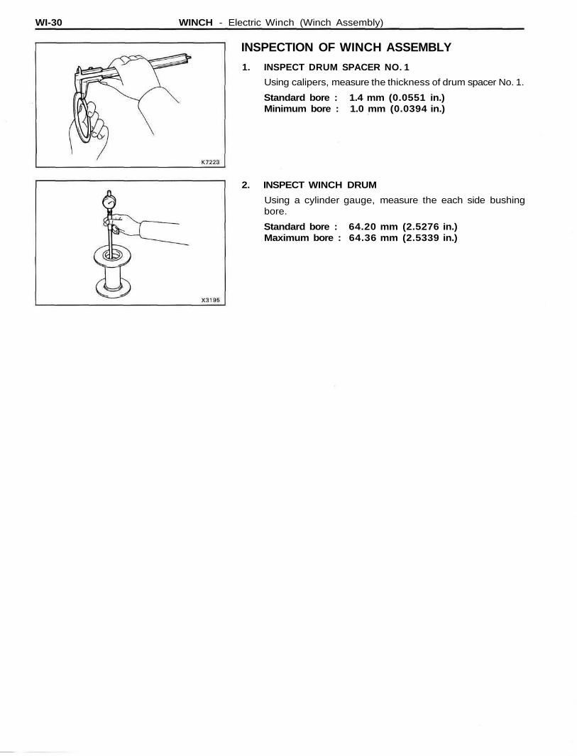
1. INSPECT DRUM SPACER NO. 1
Using calipers, measure the thickness of drum spacer No. 1.
Standard bore : 1.4 mm (0.0551 in.)Minimum bore : 1.0 mm (0.0394 in.)
2. INSPECT WINCH DRUM
Using a cylinder gauge, measure the each side bushingbore.
Standard bore : 64.20 mm (2.5276 in.)Maximum bore : 64.36 mm (2.5339 in.)
WINCH - Electric Winch (Winch Assembly) WI-31
INSTALLATION OF WINCH ASSEMBLY(See page WI-28)
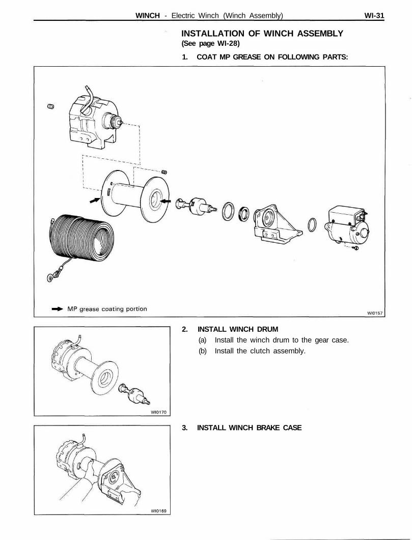
1. COAT MP GREASE ON FOLLOWING PARTS:
2. INSTALL WINCH DRUM(a) Install the winch drum to the gear case.
(b) Install the clutch assembly.
3. INSTALL WINCH BRAKE CASE
WI-32 WINCH - Electric Winch (Winch Assembly)
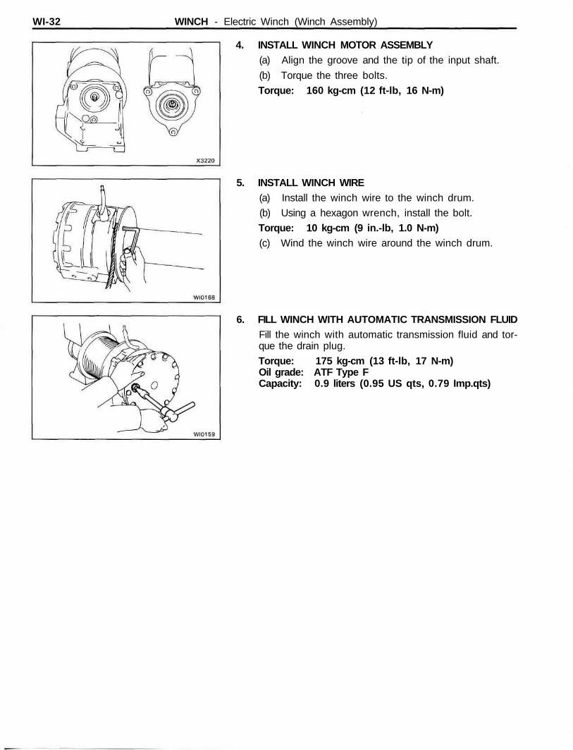
4. INSTALL WINCH MOTOR ASSEMBLY(a) Align the groove and the tip of the input shaft.
(b) Torque the three bolts.
Torque: 160 kg-cm (12 ft-lb, 16 N-m)
5. INSTALL WINCH WIRE(a) Install the winch wire to the winch drum.
(b) Using a hexagon wrench, install the bolt.
Torque: 10 kg-cm (9 in.-lb, 1.0 N-m)(c) Wind the winch wire around the winch drum.
6. FILL WINCH WITH AUTOMATIC TRANSMISSION FLUIDFill the winch with automatic transmission fluid and tor-que the drain plug.
Torque: 175 kg-cm (13 ft-lb, 17 N-m)Oil grade: ATF Type FCapacity: 0.9 liters (0.95 US qts, 0.79 Imp.qts)
WINCH - Electric Winch (Winch Components) WI-33
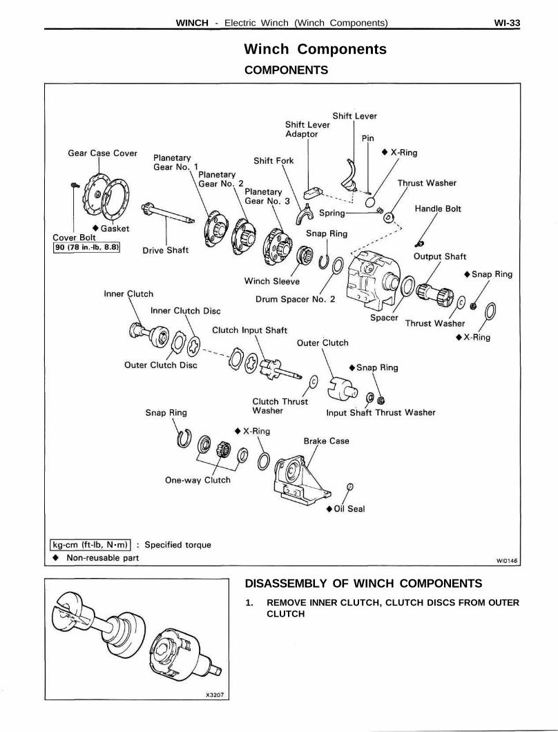
Winch ComponentsCOMPONENTS
DISASSEMBLY OF WINCH COMPONENTS
1. REMOVE INNER CLUTCH, CLUTCH DISCS FROM OUTERCLUTCH
WI-34 WINCH - Electric Winch (Winch Components)
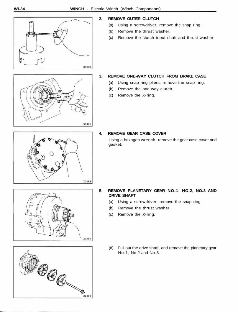
2. REMOVE OUTER CLUTCH
(a) Using a screwdriver, remove the snap ring.
(b) Remove the thrust washer.
(c) Remove the clutch input shaft and thrust washer.
3. REMOVE ONE-WAY CLUTCH FROM BRAKE CASE
(a) Using snap ring pliers, remove the snap ring.
(b) Remove the one-way clutch.
(c) Remove the X-ring.
4. REMOVE GEAR CASE COVER
Using a hexagon wrench, remove the gear case cover andgasket.
5. REMOVE PLANETARY GEAR NO.1, NO.2, NO.3 ANDDRIVE SHAFT
(a) Using a screwdriver, remove the snap ring.
(b) Remove the thrust washer.
(c) Remove the X-ring.
(d) Pull out the drive shaft, and remove the planetary gearNo.1, No.2 and No.3.
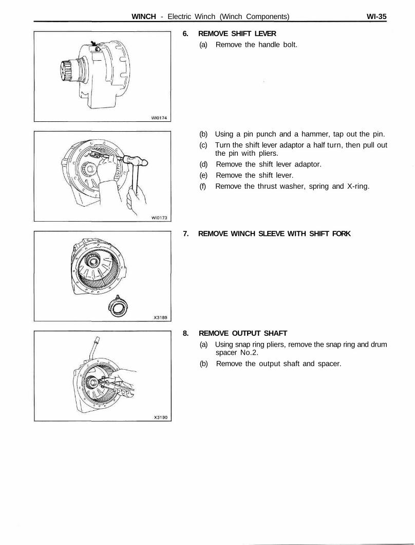
WINCH - Electric Winch (Winch Components) WI-35
6. REMOVE SHIFT LEVER(a) Remove the handle bolt.
(b) Using a pin punch and a hammer, tap out the pin.
(c) Turn the shift lever adaptor a half turn, then pull outthe pin with pliers.
(d) Remove the shift lever adaptor.
(e) Remove the shift lever.
(f) Remove the thrust washer, spring and X-ring.
7. REMOVE WINCH SLEEVE WITH SHIFT FORK
8. REMOVE OUTPUT SHAFT(a) Using snap ring pliers, remove the snap ring and drum
spacer No.2.
(b) Remove the output shaft and spacer.
WI-36 WINCH - Electric Winch (Winch Components)
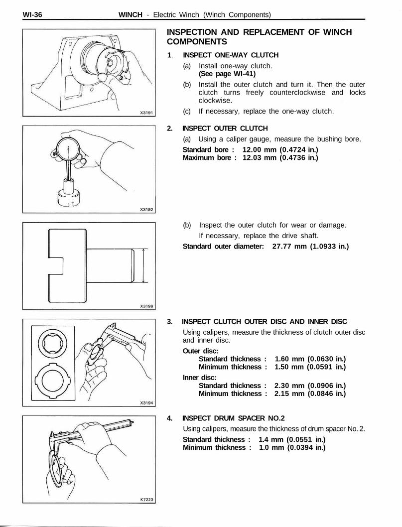
INSPECTION AND REPLACEMENT OF WINCHCOMPONENTS
1. INSPECT ONE-WAY CLUTCH(a) Install one-way clutch.
(See page WI-41)(b) Install the outer clutch and turn it. Then the outer
clutch turns freely counterclockwise and locksclockwise.
(c) If necessary, replace the one-way clutch.
2. INSPECT OUTER CLUTCH(a) Using a caliper gauge, measure the bushing bore.
Standard bore : 12.00 mm (0.4724 in.)Maximum bore : 12.03 mm (0.4736 in.)
(b) Inspect the outer clutch for wear or damage.
If necessary, replace the drive shaft.
Standard outer diameter: 27.77 mm (1.0933 in.)
3. INSPECT CLUTCH OUTER DISC AND INNER DISCUsing calipers, measure the thickness of clutch outer discand inner disc.
Outer disc:Standard thickness : 1.60 mm (0.0630 in.)Minimum thickness : 1.50 mm (0.0591 in.)
Inner disc:Standard thickness : 2.30 mm (0.0906 in.)Minimum thickness : 2.15 mm (0.0846 in.)
4. INSPECT DRUM SPACER NO.2Using calipers, measure the thickness of drum spacer No. 2.
Standard thickness : 1.4 mm (0.0551 in.)Minimum thickness : 1.0 mm (0.0394 in.)
WINCH - Electric Winch (Winch Components) WI-37
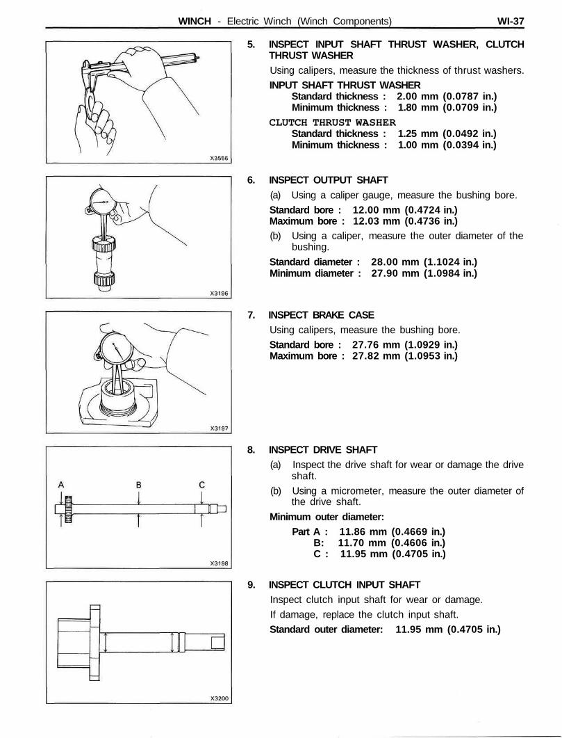
5. INSPECT INPUT SHAFT THRUST WASHER, CLUTCHTHRUST WASHERUsing calipers, measure the thickness of thrust washers.
INPUT SHAFT THRUST WASHERStandard thickness : 2.00 mm (0.0787 in.)Minimum thickness : 1.80 mm (0.0709 in.)
CLUTCH THRUST WASHERStandard thickness : 1.25 mm (0.0492 in.)Minimum thickness : 1.00 mm (0.0394 in.)
6. INSPECT OUTPUT SHAFT(a) Using a caliper gauge, measure the bushing bore.
Standard bore : 12.00 mm (0.4724 in.)Maximum bore : 12.03 mm (0.4736 in.)(b) Using a caliper, measure the outer diameter of the
bushing.
Standard diameter : 28.00 mm (1.1024 in.)Minimum diameter : 27.90 mm (1.0984 in.)
7. INSPECT BRAKE CASEUsing calipers, measure the bushing bore.
Standard bore : 27.76 mm (1.0929 in.)Maximum bore : 27.82 mm (1.0953 in.)
8. INSPECT DRIVE SHAFT(a) Inspect the drive shaft for wear or damage the drive
shaft.
(b) Using a micrometer, measure the outer diameter ofthe drive shaft.
Minimum outer diameter:Part A : 11.86 mm (0.4669 in.)
B: 11.70 mm (0.4606 in.)C : 11.95 mm (0.4705 in.)
9. INSPECT CLUTCH INPUT SHAFTInspect clutch input shaft for wear or damage.
If damage, replace the clutch input shaft.
Standard outer diameter: 11.95 mm (0.4705 in.)
WI-38 WINCH - Electric Winch (Winch Components)
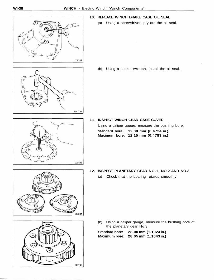
10. REPLACE WINCH BRAKE CASE OIL SEAL
(a) Using a screwdriver, pry out the oil seal.
(b) Using a socket wrench, install the oil seal.
11. INSPECT WINCH GEAR CASE COVER
Using a caliper gauge, measure the bushing bore.
Standard bore: 12.00 mm (0.4724 in.)Maximum bore: 12.15 mm (0.4783 in.)
12. INSPECT PLANETARY GEAR NO.1, NO.2 AND NO.3
(a) Check that the bearing rotates smoothly.
(b) Using a caliper gauge, measure the bushing bore ofthe planetary gear No.3.
Standard bore: 28.00 mm (1.1024 in.)Maximum bore: 28.05 mm (1.1043 in.)
WINCH - Electric Winch (Winch Components) WI-39
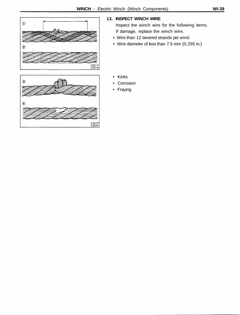
13. INSPECT WINCH WIREInspect the winch wire for the following items.If damage, replace the winch wire.
• Wire than 12 severed strands per wind.• Wire diameter of less than 7.5 mm (0.295 in.)
• Kinks
• Corrosion
• Fraying
WI-40 WINCH - Electric Winch (Winch Components)
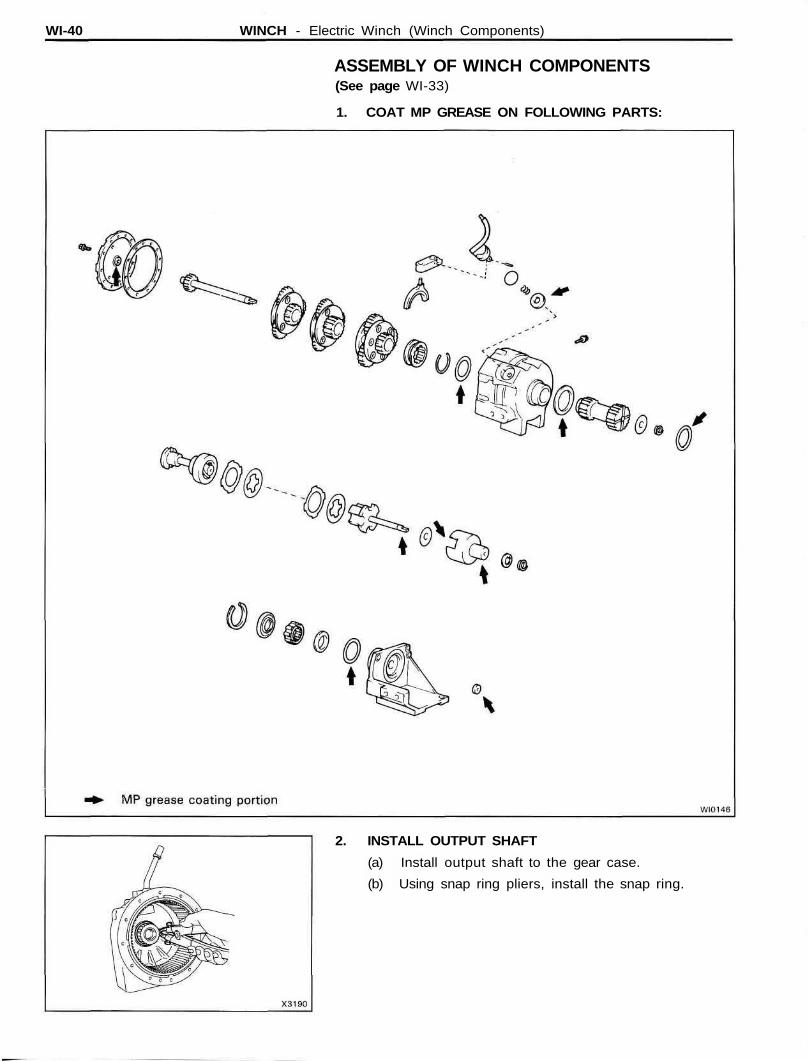
ASSEMBLY OF WINCH COMPONENTS(See page WI-33)
1. COAT MP GREASE ON FOLLOWING PARTS:
2. INSTALL OUTPUT SHAFT
(a) Install output shaft to the gear case.
(b) Using snap ring pliers, install the snap ring.
WINCH - Electric Winch (Winch Components) WI-41
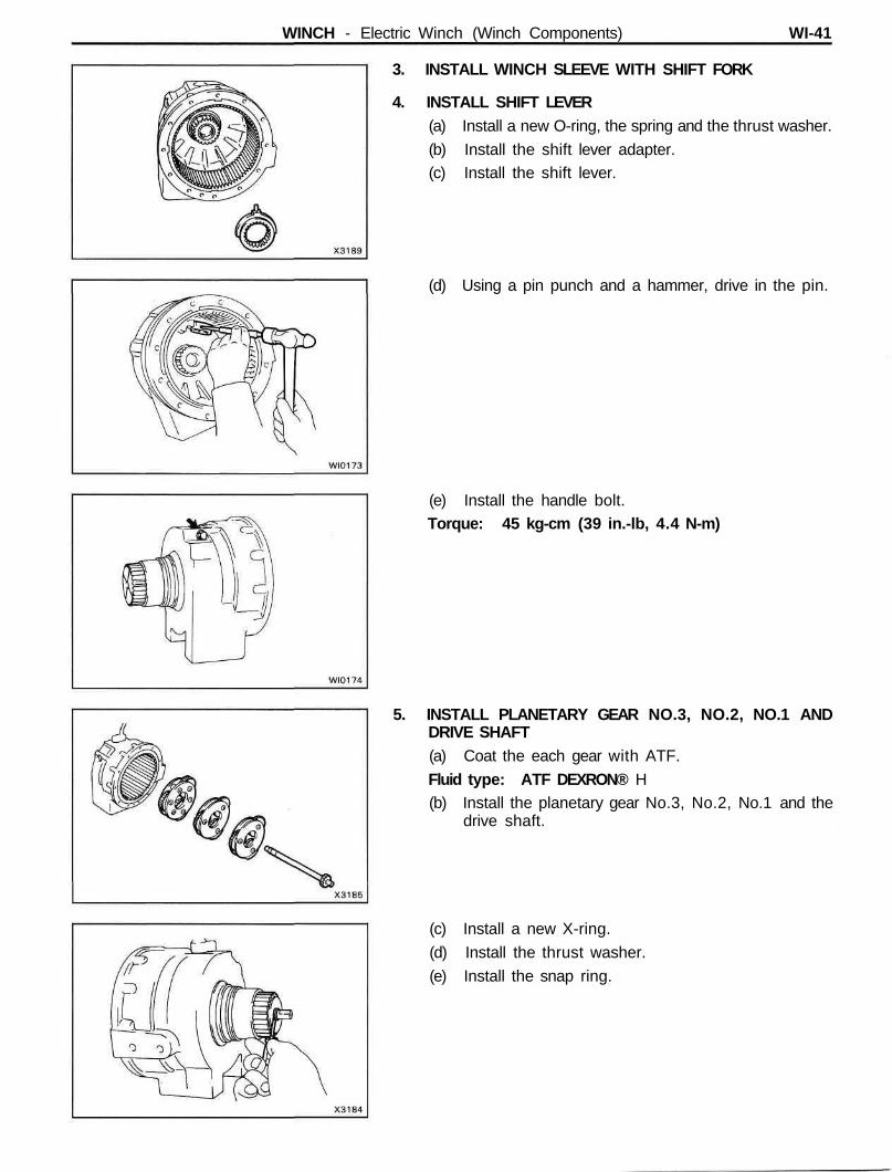
3. INSTALL WINCH SLEEVE WITH SHIFT FORK
4. INSTALL SHIFT LEVER(a) Install a new O-ring, the spring and the thrust washer.
(b) Install the shift lever adapter.(c) Install the shift lever.
(d) Using a pin punch and a hammer, drive in the pin.
(e) Install the handle bolt.Torque: 45 kg-cm (39 in.-lb, 4.4 N-m)
5. INSTALL PLANETARY GEAR NO.3, NO.2, NO.1 ANDDRIVE SHAFT(a) Coat the each gear with ATF.
Fluid type: ATF DEXRON® H(b) Install the planetary gear No.3, No.2, No.1 and the
drive shaft.
(c) Install a new X-ring.
(d) Install the thrust washer.
(e) Install the snap ring.
WI-42 WINCH - Electric Winch (Winch Components)
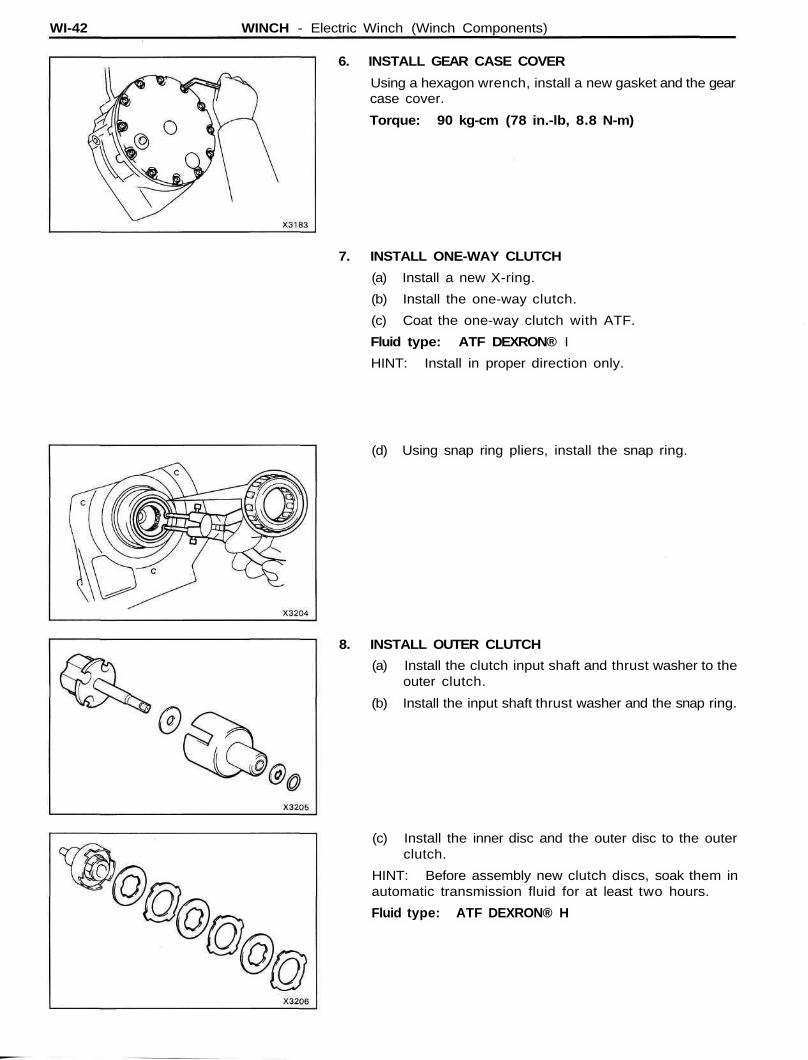
6. INSTALL GEAR CASE COVER
Using a hexagon wrench, install a new gasket and the gearcase cover.
Torque: 90 kg-cm (78 in.-lb, 8.8 N-m)
7. INSTALL ONE-WAY CLUTCH
(a) Install a new X-ring.
(b) Install the one-way clutch.
(c) Coat the one-way clutch with ATF.
Fluid type: ATF DEXRON® I
HINT: Install in proper direction only.
(d) Using snap ring pliers, install the snap ring.
8. INSTALL OUTER CLUTCH
(a) Install the clutch input shaft and thrust washer to theouter clutch.
(b) Install the input shaft thrust washer and the snap ring.
(c) Install the inner disc and the outer disc to the outerclutch.
HINT: Before assembly new clutch discs, soak them inautomatic transmission fluid for at least two hours.
Fluid type: ATF DEXRON® H
WINCH - Electric Winch (Winch Components) WI-43
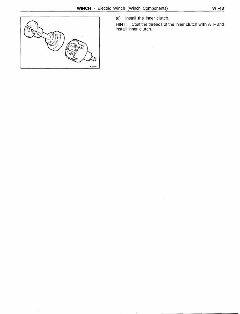
(d) Install the inner clutch.HINT: Coat the threads of the inner clutch with ATF andinstall inner clutch.
WI-44 WINCH - Electric Winch (Winch Motor)
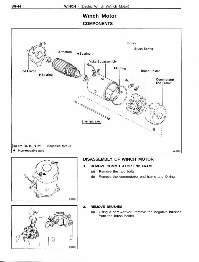
Winch MotorCOMPONENTS
DISASSEMBLY OF WINCH MOTOR
1. REMOVE COMMUTATOR END FRAME
(a) Remove the two bolts.
(b) Remove the commutator end frame and O-ring.
2. REMOVE BRUSHES
(a) Using a screwdriver, remove the negative brushesfrom the brush holder.
WINCH - Electric Winch (Winch Motor) WI-45
INSPECTION OF WINCH MOTOR
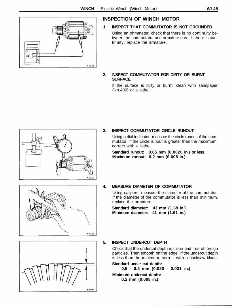
1. INSPECT THAT COMMUTATOR IS NOT GROUNDEDUsing an ohmmeter, check that there is no continuity be-tween the commutator and armature core. If there is con-tinuity, replace the armature.
2. INSPECT COMMUTATOR FOR DIRTY OR BURNTSURFACEIf the surface is dirty or burnt, clean with sandpaper(No.400) or a lathe.
3. INSPECT COMMUTATOR CIRCLE RUNOUTUsing a dial indicator, measure the circle runout of the com-mutator. If the circle runout is greater than the maximum,correct with a lathe.
Standard runout: 0.05 mm (0.0020 in.) or lessMaximum runout: 0.2 mm (0.008 in.)
4. MEASURE DIAMETER OF COMMUTATORUsing calipers, measure the diameter of the commutator.If the diameter of the commutator is less than minimum,replace the armature.
Standard diameter: 43 mm (1.69 in.)Minimum diameter: 41 mm (1.61 in.)
5. INSPECT UNDERCUT DEPTHCheck that the undercut depth is clean and free of foreignparticles. Then smooth off the edge. If the undercut depthis less than the minimum, correct with a hacksaw blade.Standard under cut depth:
0.5 - 0.8 mm (0.020 - 0.031 in.)Minimum undercut depth:
0.2 mm (0.008 in.)
WI-46 WINCH - Electric Winch (Winch Motor)
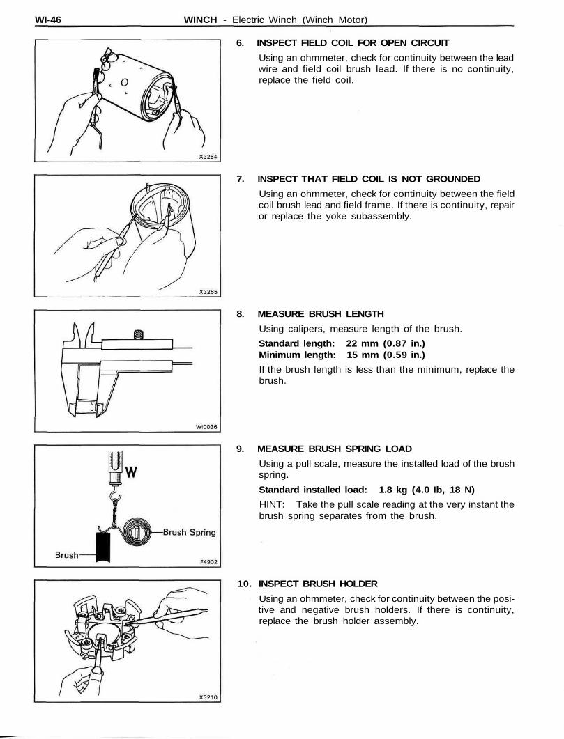
6. INSPECT FIELD COIL FOR OPEN CIRCUIT
Using an ohmmeter, check for continuity between the leadwire and field coil brush lead. If there is no continuity,replace the field coil.
7. INSPECT THAT FIELD COIL IS NOT GROUNDED
Using an ohmmeter, check for continuity between the fieldcoil brush lead and field frame. If there is continuity, repairor replace the yoke subassembly.
8. MEASURE BRUSH LENGTH
Using calipers, measure length of the brush.
Standard length: 22 mm (0.87 in.)Minimum length: 15 mm (0.59 in.)
If the brush length is less than the minimum, replace thebrush.
9. MEASURE BRUSH SPRING LOAD
Using a pull scale, measure the installed load of the brushspring.
Standard installed load: 1.8 kg (4.0 Ib, 18 N)
HINT: Take the pull scale reading at the very instant thebrush spring separates from the brush.
10. INSPECT BRUSH HOLDER
Using an ohmmeter, check for continuity between the posi-tive and negative brush holders. If there is continuity,replace the brush holder assembly.
WINCH - Electric Winch (Winch Motor) WI-47
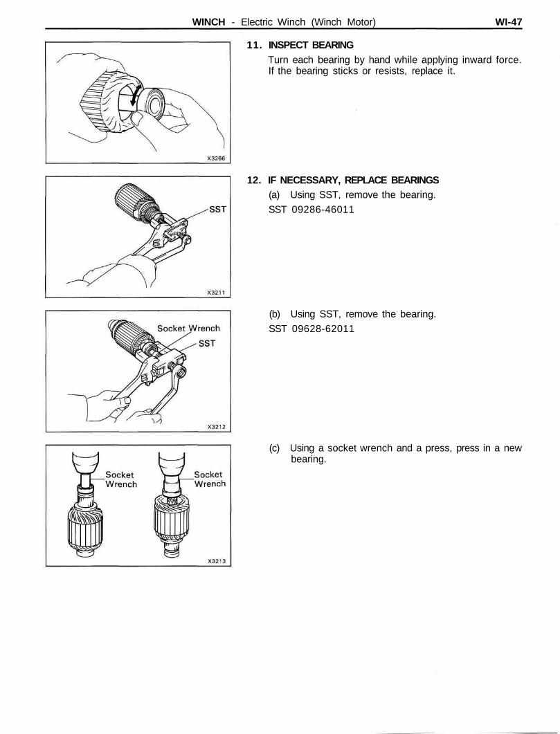
11. INSPECT BEARINGTurn each bearing by hand while applying inward force.If the bearing sticks or resists, replace it.
12. IF NECESSARY, REPLACE BEARINGS(a) Using SST, remove the bearing.
SST 09286-46011
(b) Using SST, remove the bearing.
SST 09628-62011
(c) Using a socket wrench and a press, press in a newbearing.
WI-48 WINCH - Electric Winch (Winch Motor)
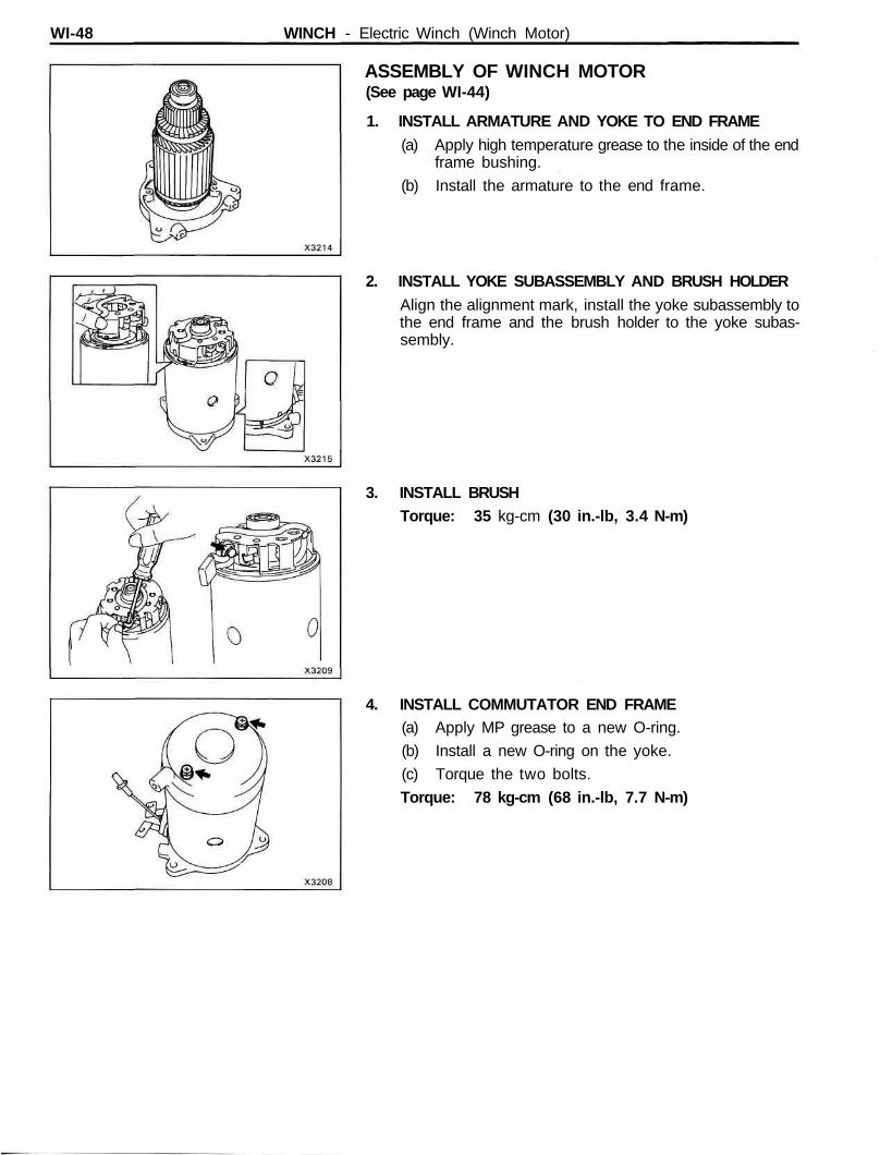
ASSEMBLY OF WINCH MOTOR(See page WI-44)
1. INSTALL ARMATURE AND YOKE TO END FRAME(a) Apply high temperature grease to the inside of the end
frame bushing.
(b) Install the armature to the end frame.
2. INSTALL YOKE SUBASSEMBLY AND BRUSH HOLDERAlign the alignment mark, install the yoke subassembly tothe end frame and the brush holder to the yoke subas-sembly.
3. INSTALL BRUSHTorque: 35 kg-cm (30 in.-lb, 3.4 N-m)
4. INSTALL COMMUTATOR END FRAME(a) Apply MP grease to a new O-ring.
(b) Install a new O-ring on the yoke.
(c) Torque the two bolts.
Torque: 78 kg-cm (68 in.-lb, 7.7 N-m)
WINCH - Electrical Winch (Magnet Switch No.1) WI-49
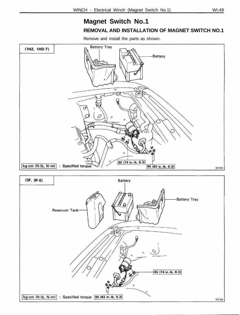
Magnet Switch No.1REMOVAL AND INSTALLATION OF MAGNET SWITCH NO.1
Remove and install the parts as shown.
WI-50 WINCH - Electrical Winch (Magnet Switch No.1)
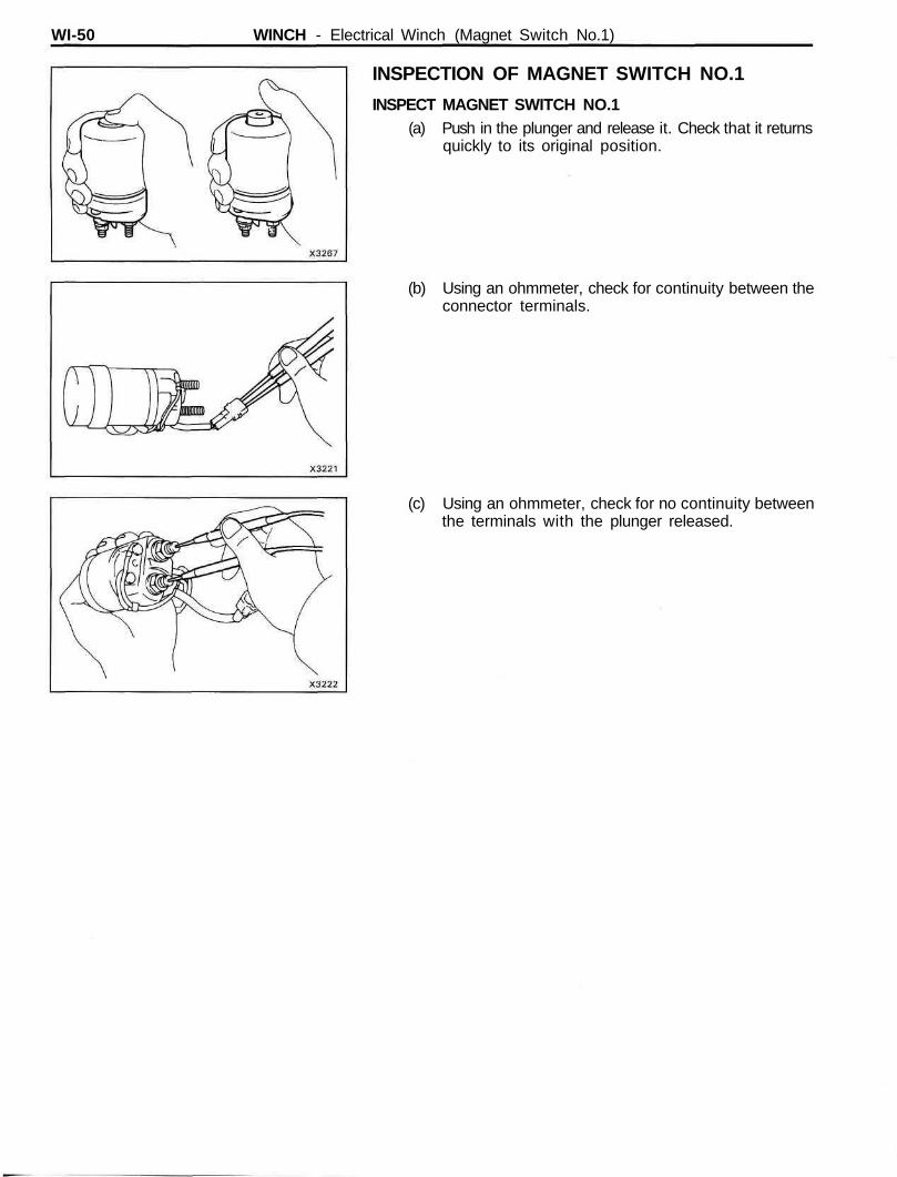
INSPECTION OF MAGNET SWITCH NO.1
INSPECT MAGNET SWITCH NO.1(a) Push in the plunger and release it. Check that it returns
quickly to its original position.
(b) Using an ohmmeter, check for continuity between theconnector terminals.
(c) Using an ohmmeter, check for no continuity betweenthe terminals with the plunger released.
WINCH - Electric Winch (Magnet Switch No.2) WI-51
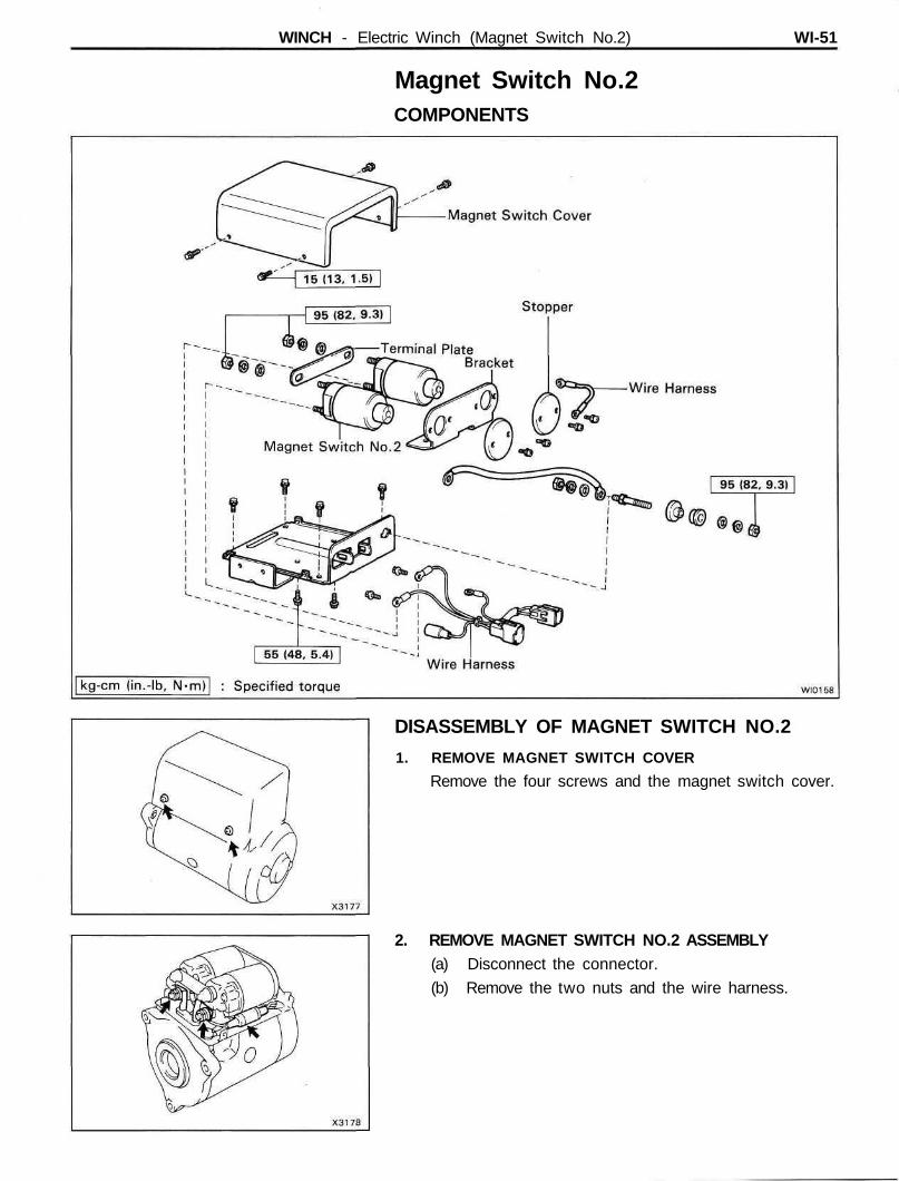
Magnet Switch No.2COMPONENTS
DISASSEMBLY OF MAGNET SWITCH NO.2
1. REMOVE MAGNET SWITCH COVER
Remove the four screws and the magnet switch cover.
2. REMOVE MAGNET SWITCH NO.2 ASSEMBLY(a) Disconnect the connector.
(b) Remove the two nuts and the wire harness.
WI-52 WINCH - Electric Winch (Magnet Switch No.2)
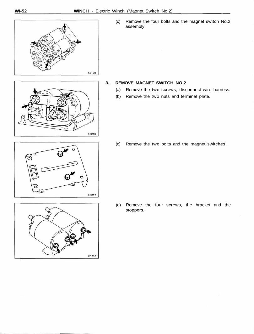
(c) Remove the four bolts and the magnet switch No.2assembly.
3. REMOVE MAGNET SWITCH NO.2
(a) Remove the two screws, disconnect wire harness.
(b) Remove the two nuts and terminal plate.
(c) Remove the two bolts and the magnet switches.
(d) Remove the four screws, the bracket and thestoppers.
WINCH - Electric Winch (Magnet Switch No.2) WI-53
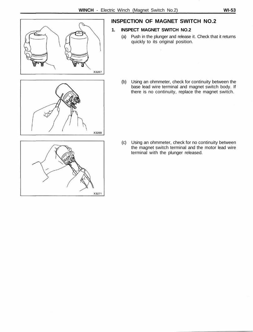
INSPECTION OF MAGNET SWITCH NO.2
1. INSPECT MAGNET SWITCH NO.2(a) Push in the plunger and release it. Check that it returns
quickly to its original position.
(b) Using an ohmmeter, check for continuity between thebase lead wire terminal and magnet switch body. Ifthere is no continuity, replace the magnet switch.
(c) Using an ohmmeter, check for no continuity betweenthe magnet switch terminal and the motor lead wireterminal with the plunger released.
WI-54 WINCH - Electric Winch (Magnet Switch No.2)
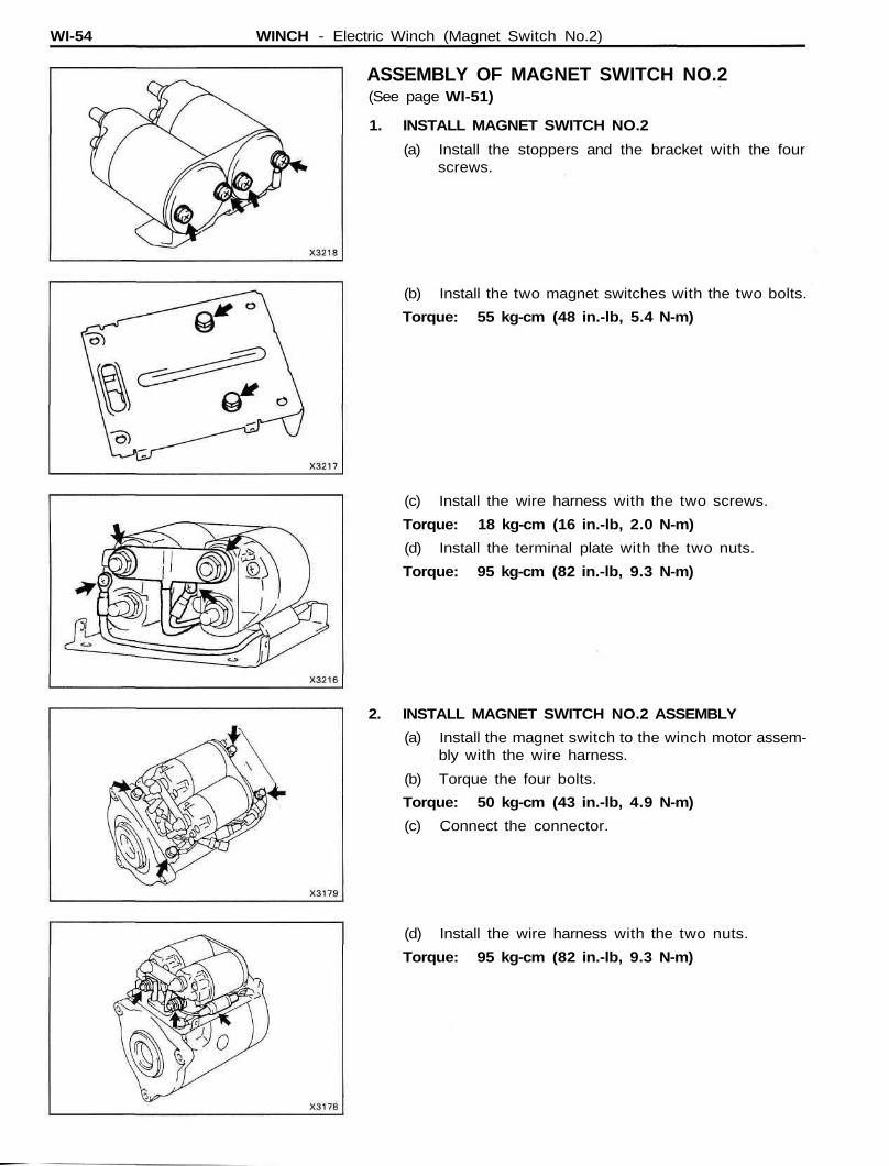
ASSEMBLY OF MAGNET SWITCH NO.2(See page WI-51)
1. INSTALL MAGNET SWITCH NO.2
(a) Install the stoppers and the bracket with the fourscrews.
(b) Install the two magnet switches with the two bolts.
Torque: 55 kg-cm (48 in.-lb, 5.4 N-m)
(c) Install the wire harness with the two screws.
Torque: 18 kg-cm (16 in.-lb, 2.0 N-m)
(d) Install the terminal plate with the two nuts.
Torque: 95 kg-cm (82 in.-lb, 9.3 N-m)
2. INSTALL MAGNET SWITCH NO.2 ASSEMBLY
(a) Install the magnet switch to the winch motor assem-bly with the wire harness.
(b) Torque the four bolts.
Torque: 50 kg-cm (43 in.-lb, 4.9 N-m)
(c) Connect the connector.
(d) Install the wire harness with the two nuts.
Torque: 95 kg-cm (82 in.-lb, 9.3 N-m)
WINCH - Electric Winch (Magnet Switch No.2) WI-55
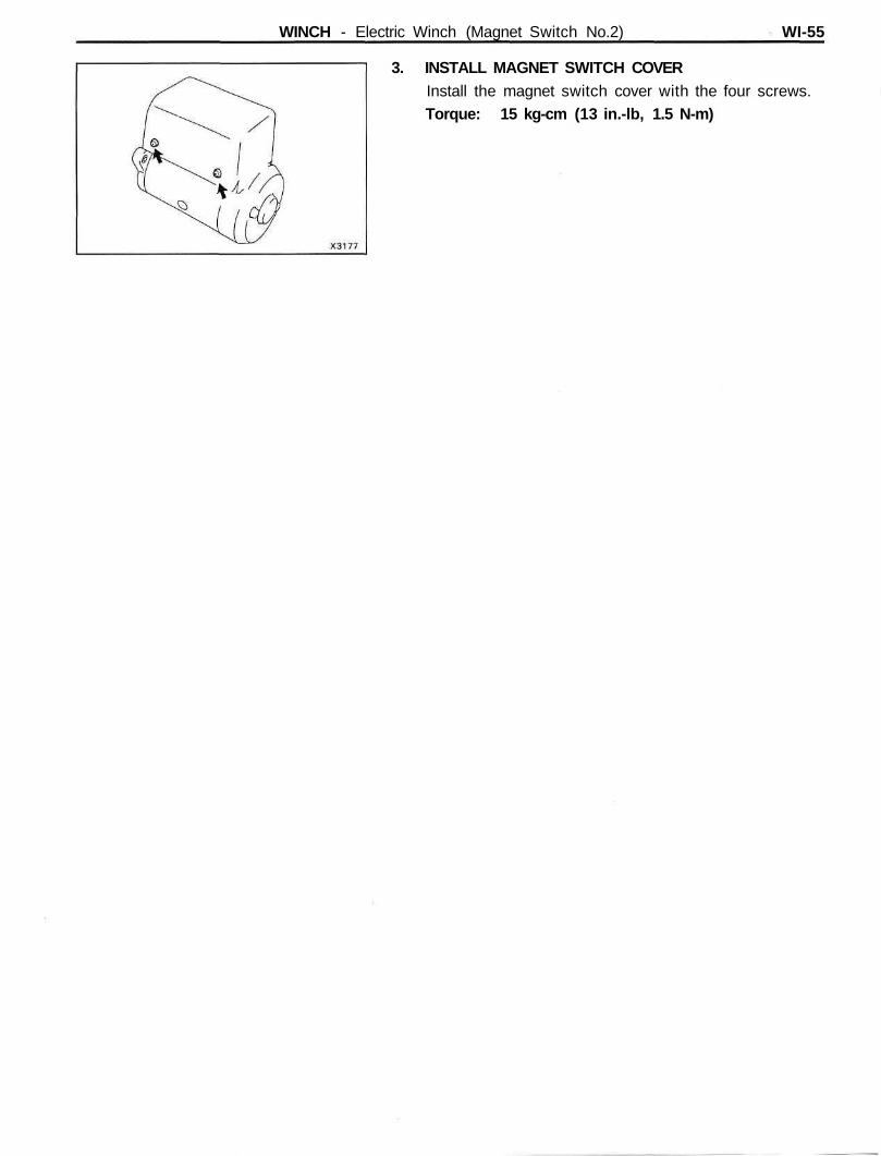
3. INSTALL MAGNET SWITCH COVERInstall the magnet switch cover with the four screws.Torque: 15 kg-cm (13 in.-lb, 1.5 N-m)