wide-area wireless networks (wans) – gsm evolution
TRANSCRIPT

Wide-Area Wireless Networks(WANS) – GSM Evolution
Chapter 15 - 15.2
ByDonavon M. Norwood
SJSUCS286
Dr. Melody Moh08/05/2009

2
Introduction - 15.1
Third-generation (3G) wireless systems offer access to services anywhere from a signal terminal and the old boundaries between telephony, information and entertainment services are disappearing. The applications on a 3G wireless network range from simple voice-only communications, simultaneous video, data and other multimedia applications. One of the main benefits of 3G is that it allows a broad range of wireless services to be provided efficiently to many different users. Packet based Internet protocol (IP) technology is at the core of the 3G services. Email message are able to arrive at mobile devices and business users are able to stay connected to the intranet permanently. In 1997 the TIA/EIA IS-136 community through the Universal Wireless Consortium (UWC) and the Telecommunications Industry Association (TIA) TR 45.3 adopted a three part strategy for migrating existing IS-136 TDMA based networks (2G) to 3G wireless networks:
• Enhance voice/data capabilities of existing 30 kHz carrier (IS-136+)• Adding a 200 kHz carrier for high speed data (384 kbps) in high mobility
applications.• Introducing a 1.6 MHZ carrier for a very high speed data (2 Mbps) in low
mobility applications.

3
Figure 15.1 User data requirements

4
GSM Evolution for Data - 15.2
From a radio access perspective adding 3G capabilities to a 2G system means supporting higher data rates. The possible scenarios depend on the spectrum fallibility for the network service provider. Two different migration paths can be supported:
• Reframing of existing spectrum bands• New or modified spectrum bands
Two different 3G radio access schemes are identified to support the different spectrum scenarios:
• Enhanced data rates fir GSM evolution (EDGE) with high level modulation in a 200 Khz TDMA channel is based on plug-in transceiver equipment which allows the migration of the existing bands into smaller spectrum segments.
• Universal mobile telecommunications services (UMTS) which is a new radio access network based on 5 MHz WCDMA and optimized for efficient support of 3G services, and can be used in new/existing spectra.
GSM operators have two options for integrating their networks to 3G wideband operation: 1) using GPRS with EDGE in existing radio spectrum and in small amounts in new spectrum 2) using WCDMA in the new 2 GHz bands or in large amounts of the existing spectrum

5
High Speed Circuit Switched Data - 15.2.1
High speed circuit switched data (HSCSD) is a feature that enables the co-allocation of multiple full rate traffic channels (TCH/F) of GSM into an HSCSD configuration. The goal for using HSCSD is for providing a mixture of services with different air user rates by a single physical layer structure. The available capacity of an HSCSD configuration is several times the capacity of a TCH/F, which would lead to a significant enhancement in air interface data transfer capability. For operators a migration to HSCSD enabled standard software upgrades to the BS and MSC equipment. For end users, HSCSD enables the roll out of mainstream high-end segment services that will enable faster web browsing, file downloads, mobile video-conferencing and navigation, vertical applications, telematics and bandwidth-secure mobile LAN access. HSCSD is provided within existing mobility management and roaming is also possible.

6
General Packet Radio Service - 15.2.2
The general packet radio service (GPRS) enhances GSM data services by providing end-to-end packet switched data communications which is efficient in Internet/intranet traffic, where short burst of intense data communication are actively interspersed with relatively long periods of inactivity. Since GPRS does not require any dedicated end-to-end connection, it will use only network resources and bandwidth when data is actually transmitted, which means that a given amount of bandwidth can be shared efficiently among many users at the same time. GPRS has been standardized to optimally support a wide range of applications ranging from very frequent transmissions of medium to large data volume. A similar strategy has been implemented for GPRS has been developed for DAMPS (IS-136). If operators want to use wideband multimedia services the move to GPRS packet based data bearer service would be significant, because the migration to GPRS would be a small step compared to building a totally new 3G IMT-2000 network. Use of the GPRS network architecture for IS-136+ packet data service enables data subscription roaming with GSM networks around the globe that support GPRS and its evolution. GPRS-136 provides the same capabilities as GSM GPRS, and users can access either X.25 or an IP based network.

7
Figure 15.2 A GPRS architecture in GSM

8
General Packet Radio Service – 15.2.2(Continued)
GPRS can be implemented into the existing GSM systems. Changes are required in an existing GSM network to introduce GPRS. The BSS consists of a BSC and a packet control unit (PCU). The PCU supports all GPRS protocols for communication over the air interface, and its function is to set up, supervise, and disconnect packet switched calls. The BTS is a relay station without protocol functions and it also performs modulation/demodulation. The two new nodes in the GPRS system are the serving GPRS support node (SGSN) and the gateway GPRS support node (GGSN). The HLR is enhanced with GPRS subscriber data and routing information. There are two types of GPRS services:
– Point-to-point (PTP)– Point-to-multipoint (PTM)
Packet routing and transfer within the public land mobile network (PLMN) is supported is supported by the GGSN. The GGSN at the source encapsulates PDUs and at the destination GGSN PDUs are decapsulated in which IP is used as the backbone to transfer PDUs. The GGSN also contains routing data used to tunnel PDUs to the SGSN serving the mobile station (MS). In essence the GGSN provides the gateway to external networks.

9
General Packet Radio Service – 15.2.2(Continued)
The SGSN serves the mobile and performs security and access control functions. The SGSN is connected to the BS via frame-relay. The SGSN provides all packet routing, mobility management, authentication, and ciphering to and from all GPRS subscribers located in the SGSN service area. Traffic is routed from the SGSN to the BSC, from the BSC to the BTS, and from the BTS to the MS. The HLR contains GPRS subscription data and routing information which can be accessed from the SGSN. For roaming mobiles, the HLR may reside in a different PLMN than the current SGSN. The GGSN again contains routing information for the attached GPRS users. The routing information is used to tunnel PDUs to the mobiles users point of attachment SGSN. The GGSN is the first point of public data network (PDN) interconnection with a GSM PLMN supporting GPRS. From an external network view, the GGSN owns all the ip addresses of all the subscribers served by the GPRS network. The objective of GPRS design is to maximize the use of existing GSM infrastructure while minimizing the changes required within GSM.

10
Figure 15.3 GPRS interfaces for different network elements

11
MS-SGSN Link
The logical link control (LLC) layer is responsible for providing a link between the MS and the SGSN. It also governs the transport of GPRS signaling and traffic information from the MS to the attached SGSN. GPRS supports three service access points (SAPs) entities:
* Layer 3 management* Subnet dependent convergence * Short message service (SMS)
On the MS-BSS link, the radio link control (RLC), medium access control (MAC) and GSM RF protocols are also supported. The man drawback with implementing GPRS in a GSM network is that the GSM network is optimized for voice transmission, therefore it is expected that GPRS could have varied transmission performance in a different network or coverage area. To overcome this problem, GPRS supports multiple coding rates at the physical level.

12
Figure 15.4 Protocol stack in GPRS

13
MS-SGSN Link (Continued)
A GPRS Channel is allocated only if an active GPRS terminal exists in the network. Once resources are allocated to GPRS, at least one channel will serve as the master channel to carry all signaling and control information for the operation of the GPRS. All other channels will serve as slave channels and are used to carry user or signaling information. If no master channel exists all GPRS users will use the GSM common control channel (CCCH) and inform the network to allocate GPRS resources. A physical channel dedicated to GPRS is called packet data channel (PDCH). It is mapped into one of the physical channels allocated to GPRS. A PDCH can either be used as a packet common control channel (PCCCH), a packet broadcast control channel (PBCCH) or a packet traffic channel (PTCH).

14
Figure 15.5 GPRS logical channels

15
RLC/MAC Layer
The multiframe structure of the PDCH in which GPRS RLC messages are transmitted is composed of 52 TDMA frames organized into RLC blocks of four bursts resulting in 12 blocks per multiframe plus four idle frames located in the 13th, 26th, 39th, and 52nd positions. B0 consists of frames 1-4, B4 consists of frames 5-8, etc. The mapping of of logical channels onto the radio blocks is done by means of an ordered set of blocks (B0, B6, B9, B1, B7, B4, B10, B2, B8, B5, B11). The advantage of ordering the blocks is mainly to spread the locations of the control channels in each time slot reducing the average waiting time for the users to transmit signaling packets.
Figure 15.6 Idle frame location in GPRS multiframe

16
LLC Layer
The LLC layer is responsible for providing a reliable link between the mobile and the SGSN. It is based on the LAPD (link access protocol D) protocol, which is designed to support variable length transmission in a PTP or PTM topology. It also includes the layer function such as sequence control, flow control, error detection, ciphering, and recovery as well as the provision of one or more logical link connections between two layer 3 entities. A logical link is identified by a DLCI (data link control identity) which consists of a service access point identity (SAPI) and a terminal equipment identity (TEI) mapped on the LLC frame format.
17
Data Packet Routing in the GPRS Network
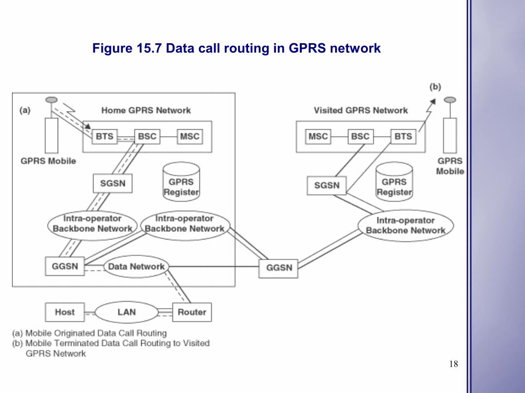
In mobile originated data routing, a mobile gets an IP packet from an application and request a channel reservation. The mobile transmits data in reserved time slots. The packet switched public data network (PSPDN) PDU is encapsulated into a sub-network dependent convergence protocol (SNDCP) that is sent via LLC protocol over the air interface to the SGSN currently serving the mobile. For mobile terminated data two cases can be used: routing to the home GPRS network and routing to a visited GPRS network. In the first example a user sends a data packet to the mobile which goes through the users LAN via a router out to the GPRS context of the MS. If the MS is idle the data packet is rejected and if the MS is in standby or active mode, the GGSN routes the data packet in an encapsulated format to the SGSN. In the second example the home GPRS network routes the data packet over the inter-operator backbone network to the visiting GPRS network and the visiting GPRS network routes the data packet to the appropriate SGSN.
18
Figure 15.7 Data call routing in GPRS network

19
Enhanced Data Rates for GSM Enhancement (EDGE) - 15.2.3
Enhanced Data Rates for GSM Enhancement (EDGE) can provide a evolution path to existing 2G systems (GSM, IS-136, PDC) to deliver some 3G services in existing spectrum bands. EDGE advantages include fast availability, reuse of existing GSM, IS-136, and PDC infrastructure and the introduction to 3G capabilities. EDGE is primarily a radio interface improvement but it can also be viewed as a way to provide GSM, IS-136, and PDC networks a set of new services with 3G capabilities. EDGE has been designed to improve S/I by using link quality control which adapts the protection of the data to the channel quality so that for all channel qualities an optimal bit rate is achieved. EDGE can also be seen as a generic air interface for efficiently providing high bit rates, facilitating an evolution to existing 2G systems towards 3G systems, and the EDGE interface is designed to provide higher bit rates than those currently in 2G systems. EDGE uses both the 8-PSK and GMSK modulation schemes with a symbol rate of 271 kbps for both which leads to a gross bit rate per time slot of 69.2 kbps and 22.8 kbps respectively. The 8-PSK pulse shape is linearized by GMSK to allow 8-PSK to fit into the GSM spectrum mask.

20
Figure 15.8 Burst format for EDGE with 8-PSK
21
Enhanced Data Rates for GSM Enhancement (EDGE) – 15.2.3(Continued)
EDGE also known as 2.5G has been designed to enhance user bandwidth through GPRS which is achieved by using higher level modulation schemes. EDGE has two standardization phases which consists of enhanced GPRS (EGPRS) and enhanced CSD (ECSD) and the second phase being with the improvement for multimedia and real-time services. Radio protocol design in EDGE is to reuse the protocols of GSM/GPRS whenever possible which eliminates the need for new protocol implementation. EDGE enhances the GSM circuit-switched (HSCSD) and packet-switched (GPRS) mode operation. EDGE includes one packet-switched and one-circuit switched mode which is EGPRS and ECSD respectively.
Enhanced GPRS (EGPRS)
EDGE RLC protocol is different from the GPRS RLC protocol with main changes related to the improvements in link quality control scheme. A link adaption scheme regularly estimates the link quality and then selects the most appropriate modulation and coding scheme for the transmission to maximize the user bit rate. This link adaption scheme also offers a mechanism for choosing the best modulation scheme. Another way to handle link quality is through incremental redundancy in which information is sent with little coding which yields a high bit rate if decoding is immediately successful. The more coding that has to be sent results in a lower bit rate and higher delay.

22
Enhanced Data Rates for GSM Enhancement (EDGE) – 15.2.3(Continued)
Enhanced GPRS (EGPRS)
EGPRS supports combined link adaption and incremental redundancy schemes, in which the initial code rate and the incremental redundancy schemes are based on measurements of link quality. The benefit of this approach are robustness and high throughput of the incremental redundancy operation in combination with lower delays and lower memory requirements enabled by the adaptive initial code rate. In EGPRS the different initial code rates are obtained by puncturing a different number of bits from a common convolutional code R = 1/3. Incremental redundancy operation is enabled by puncturing a different set of bits each time a block is transmitted and the code rate is gradually decreased by 1/3 for every new transmission of the block.

23
Enhanced Data Rates for GSM Enhancement (EDGE) – 15.2.3(Continued)
Enhanced CSD (ECSD)
In the case of Enhanced CSD (ECSD) the objective is to keep the existing GSM CS data protocols as intact as possible. In order to provide higher data rates, multislot solutions as in ESCD are provided in EDGE which have no impact on link or system performance. A data frame is interleaved over 22 times just like in GSM and three new 8-PSK channel coding schemes are defined along with four already for GSM. Fast introduction to EGPRS/ESCD services is possible by reusing the existing transponder rare adapter unit (TRAU) formats and 16 kbps channel structure several times on the interface. Abis

24
Enhanced Data Rates for GSM Enhancement (EDGE) – 15.2.3(Continued)
EDGE Implementation
EDGE makes use of GSM infrastructure in a highly efficient manner. Radio network planning will not be greatly affected since it will be possible to reuse many existing BTS sites. GPRS packet switching nodes will no be affected either because they function independently of user bit rates and any modifications to the switching nodes will be limited to software upgrades. Keeping GSM as the core network for the provision of the 3G wireless services has additional benefits which include protecting the investment of operators, helping ensure the widest possible customer base from the outset and it fosters supplier competition through the continuous evolution of systems. Building on an existing GSM infrastructure will be relatively fast and inexpensive compared to creating a totally new 3G system from the ground up. The move first to GPRS and later to EDGE will make the transition to 3G easier.

25
THANK YOU
References: Wireless and Data Communications and Networking, Vijay K. Garg