wide belt owner's manual 2012 - safety speed€¦ · wide belt sander owner’s manual model...
TRANSCRIPT

Wide Belt Sander
Owner’s Manual
Model 3760 Model 4375
Safety Speed Manufacturing 13943 Lincoln Street NE
Ham Lake, MN 55304 Tel: 763-755-1600 Fax: 763-755-6080
www.safetyspeed.com [email protected]

Table Of Contents
Warranty - - - - - - - - - - - - - - - - - - - - - - - - - 4 Safety Information - - - - - - - - - - - - - - - - 5-6
Set Up - - - - - - - - - - - - - - - - - - - - - - - - - 7-10 -Electrical Service Requirements - - - - - - - - - 8 -Single Phase - - - - - - - - - - - - - - - - - - - - - - - 8 -Three-phase Electrical Service (230v) - - - - - 9 -Air Service - - - - - - - - - - - - - - - - - - - - - - - - 10 -Dust Collection - - - - - - - - - - - - - - - - - - - - - 10
Introduction To The Components - - 11-18 -Load Meter - - - - - - - - - - - - - - - - - - - - - - - 11 -Air Control - - - - - - - - - - - - - - - - - - - - - - - - 11 -Sanding Heads Start Control - - - - - - - - - - - 12 -Sanding Head Stop Control - - - - - - - - - - - - 12 -Emergency Stop Locations - - - - - - - - - - - - 13 -Conveyor Table Speed Adjustment Controls 14 -Conveyor Table Height Adjustment Gauges 15 -Gauge With Ruler And Indicator - - - - - - - - 15 -Simple Stationary Pointer - - - - - - - - - - - - - 16 -Optional Digital Positioning Gauge System - 16 -Abrasive Belt Tracking System - - - - - - - 17-18
Sanding Operations- - - - - - - - - - - - - - 19-28 -Operational Checklist - - - - - - - - - - - - - - - - 19 -Abrasive Sanding Belt General Information - 20 -Abrasive Sanding Belt Installation - - - - - - - 21 -Operating The Machine - - - - - - - - - - - - - 22-24 -Introduction To The Platen - - - - - - - - - - - - 25 -37” X 60” Model Platen - - - - - - - - - - - - - - - 26 -Installing and Using the Platen - - - - - - - - - - 26 -4375 Series Models Platen- - - - - - - - - - - - - 27 -Platen Removal 4375 - - - - - - - - - - - - - - - - 28
Maintenance - - - - - - - - - - - - - - - - - - - 29-40 -Repairs - - - - - - - - - - - - - - - - - - - - - - - - - - - 29 -Lubrication - - - - - - - - - - - - - - - - - - - - - - - - 29 -Sanding Head Rollers - - - - - - - - - - - - - - - - 29 -Conveyor Table Rollers- - - - - - - - - - - - - - - - 29 -Bronze Bushings - - - - - - - - - - - - - - - - - - - - 29 -Jack Screws - - - - - - - - - - - - - - - - - - - - - - - 29 -Conveyor Drive Gear Reducer - - - - - - - - - - - 30 -Swing Arm Top Idler Roller - - - - - - - - - - - - - 30 -All Metal Moving Parts - - - - - - - - - - - - - - - - 30 -Drive Motor Belt Tension - - - - - - - - - - - - - - 30 -Platen Graphite Replacement - - - - - - - - - - - 31 -Platen Felt Replacement - - - - - - - - - - - - - - 32 -Contact Roller Resurfacing - - - - - - - - - - - - - 33 -Contact Roller Removal/Replacement - - - - - 34 -Contact Roller Reinstallation - - - - - - - - - - - - 35 -Re-leveling The Contact Roller - - - - - - - - - - 35 -Pinch Roller and Idler Roller Replacement - - 36 -Rear Idler Roller Leveling - - - - - - - - - - - - - - 37 -Level The Table - - - - - - - - - - - - - - - - - - - - 37 -Level The Conveyor Table - - - - - - - - - - - - - 38 -Wide Belt Sander Belt Tracking - - - - - - - - - - 39 Trouble Shooting - - - - - - - - - - - - - - - - - 41-44 -Machine Will Not Start - - - - - - - - - - - - - - - - 41 -Unwanted Surface Marks - - - - - - - - - - - 41-42 -Sanding Belt Tracking - - - - - - - - - - - - - - 42-44 Exploded Views and Parts List - - - - - - 45-60 -4375 Exploded Views and Parts - - - - - - 45-52 -3760 Exploded Views and Parts - - - - - - 53-59 Electrician Wiring Schematics - - - - - - - 60-61 -Single Phase Wiring Schematic - - - - - - - - - -60 -Three Phase Wiring Schematic - - - - - - - - - - 61
2

This page was intentionally left blank.
3

The information in this manual covers the following models: WBS 3760 WBS 4375 The manual is provided to assist operators and service people in the proper upkeep and maintenance of Safety Speed units. This manual is published for informational purposes only and the information so provided should not be considered as all-inclusive or covering all contingencies. If further information is required, Safety Speed Manufacturing should be consulted.
Warranty
Safety Speed Mfg. warrants the parts and workmanship of this tool for one year from the date of manufacture. Safety Speed Mfg. will repair or replace, at our cost, any component that is
determined to be defective.
Such repair or replacement is limited to providing satisfactory replacement parts from our factory.
Safety Speed Mfg. assumes no responsibility for making repairs on site.
Any parts returned to the factory must be returned freight prepaid.
Safety Speed Mfg. assumes no responsibility for damage or accidents resulting from the misuse of this tool, its misapplication, or failure to follow precautionary safety measures.
Safety Speed Mfg. assumes no responsibility for any consequential damage or loss of production.
Safety Speed Mfg. will not be responsible for claims made for machines that are not used or maintained in the normal course of business, used for applications not intended, or modified in
any way.
A message from all of us at Safety Speed Manufacturing
Thank you for purchasing a Safety Speed Wide Belt Sander. We take pride in building these fine products in the U.S.A. Each product is designed to give years of dependable service. Our wide belt sanders are built from the finest components we can specify. Every machine is individually assembled by our employees, some of whom have been building products for the industry for more than 25 years. We appreciate that you chose our products for your applications.
The employees of Safety Speed Manufacturing Ham Lake, MN

Safety
5
Read And Save All Instructions For Future Use WARNING: Always follow basic safety precautions when using electrical tools. This will reduce the risk of fire, electrical shock, and personal injury. Safety Information
You must read and understand this manual before using the equipment. You must also read any labels and safety warnings packaged with or attached to this unit.
USE COMMON SENSE AT ALL TIME!
KNOW YOUR POWER TOOL. You must read this manual carefully to learn your power tool’s applications and limitations. Before operation it is important that you know the potential hazards associated with this type of tool.
DO NOT ALLOW UNQUALIFIED PEOPLE TO OPERATE THE MACHINE.
AVOID DANGEROUS ENVIRONMENTS. Do not use your power tool in damp or wet locations. Do not use your power tool in the presence of explosive atmospheres (gaseous fumes, dust, or flammable materials). Remove all materials or debris that may be ignited by sparks.
KEEP WORK AREA CLEAN AND WELL LIT. Cluttered, dark work areas invite accidents. Provide at least 200 watts of lighting at the front work area of the machine. Eliminate all shadows that could interfere with clear viewing of the work area.
DRESS PROPERLY. Do not wear loose fitting clothing or jewelry. Wear a protective hair covering to contain long hair. Unprotected hair may be caught in moving parts. When working outdoors wear rubber gloves and insulated non-skid footwear. Keep hands and gloves away from moving parts.
USE SAFETY EQUIPMENT. Everyone in the work area should wear safety goggles or glasses with side shields. The safety goggles and/or glasses should comply with current safety standards. Wear hearing protection during extended use of the machine. Wear a dust mask for dusty operations. Hard hats, face shields, safety shoes, etc. should be used when specified or necessary. Keep a fire extinguisher nearby.
KEEP BYSTANDERS AWAY. Keep children and bystanders at a safe distance from the work area.
MAKE THE WORKSHOP CHILD PROOF.
Install padlocks and master switches, etc. to make the workshop child proof.
NEVER LEAVE THE MACHINE RUNNING UNATTENDED. Turn the power off. Do not leave the machine until it comes to a complete stop.
PROTECT OTHERS IN THE WORK AREA FROM DEBRIS. Provide barriers or shields as needed to protect others in the work area from flying debris such as chips and sparks.
SECURE THE WORK. Hold your work securely with a clamp, vice or other practical means. This will free both hands to control the machine.
USE THE RIGHT MACHINE/TOOL. Do not use the machine or any of its attachments to do a job for which it is not recommended. Do not alter the tool, remove guards or operate the machine without all proper guarding in use.

6
Safety
USE PROPER ACCESSORIES. Using non-recommended accessories may be hazardous. Be sure accessories are properly installed and maintained. Do not defeat the purpose of a guard or other safety device when installing an accessory or attachment.
CHECK FOR DAMAGED PARTS. Inspect guards and other parts before use. Check for misalignment, binding of moving parts or improper mounting of parts. Also check for broken parts and other conditions that may affect operation. Turn the tool off immediately if abnormal noise or vibration occurs. Have the problem corrected before further use. Do not use a damaged tool. Tag damaged parts “DO NOT USE” until repaired. Repair or replace a damaged guard or other damaged parts. For all repairs, insist on an identical replacement part.
REMOVE ALL ADJUSTING WRENCHES AND TOOLS FROM THE MACHINE BEFORE TURNING IT ON.
GROUND YOUR MACHINE. When in doubt as to the grounding of your machine, consult a qualified electrician before using your machine.
AVOID ACCIDENTAL STARTING. Do not use the tool if the power switch does not turn it on and off. Observe correct lock-out tag procedures when performing maintenance on your machine.
DO NOT FORCE THE TOOL. Your tool will perform best at the rate for which it was designed. Excessive force only causes operator fatigue. Excessive force also causes increased machine wear and increased risk. This all can cause reduced control of the machine and results in a danger to the operator.
KEEP HANDS AWAY FROM ALL CUTTING, SANDING EDGES, HOLDDOWNS AND MOVING TABLE PARTS.
DO NOT ABUSE THE POWER CORD. Keep the cord and other wiring away from heat, oil, sharp objects, cutting tools and moving parts.
DO NOT OVER REACH. MAINTAIN CONTROL. Keep proper footing and balance at all times. Maintain a firm grip.

Set Up
7
Set Up
Complete the following steps to prepare your machine for use.
1. Remove the machine from the pallet. It is recommended to lift the machine from the underside of the machine, between the legs. See Fig. 2. It is important to rememberthat the machine is very heavy and unstable until it is secured to the floor.
2. Position the machine in its designated location in your shop. Consider the services of compressed air, dust collection and electricity. Also position the machine considering your environment’s limitations for in-feed and out-feed space. See Fig. 1.
Mount the machine to the floor. Use the holes on each of the four corners of the machine frame to mount it to the floor. See Fig. 3.
Place Moving Jacks
Here
Figure 1: Machine Dimesions
Model 3760 A = 50 1/2” (1280mm) B = 63” (1600mm) C = 47” (1190mm)
Weight=1400 lbs (635 kg)
Model 4375 A = 53” (1346mm) B = 70” (1780mm) C = 56” (1422mm)
Weight= 2389 lbs. (1083 kg)
Figure 2: Place Moving Jacks Here
Mounting Holes
Mounting Holes
Figure 3: Mounting Holes

Set Up
8
Electrical Service Requirements
Electrical servicing of the machine must be completed by an experienced, licensed electrician.
NOTE: Refer to the exploded view and parts list in the back of the manual for a full view of the electrical components.
CAUTION: Electrical servicing of the machine must be completed by an experienced, licensed electrician.
Single Phase
To connect the unit in a single phase operation, complete the following steps.
1. Connect 220 volt services to the positions labels L-1 and L-2 on the main magnetic starter. See Fig. 4 & 5.
2. Connect the ground wire from the service to the grounding bar inside the control panel. See Fig. 6.
Connect the neutral wire from the service to the wire labeled “neutral.” See Fig. 6.
NOTE: If there is not a neutral wire in the incoming service, then connect the small neutral wire from the machine to the grounding bar. This may already be connected from the factory but should be double checked by your electrician as part of the wiring procedure.
L-1
L-2
Ground Wire
Neutral Wire
Pig Tail Neutral
L-3
Figure 4: Electrical Connections
Grounding Bar
Neutral Wires
Magnetic Starter
L-2
L-1
Figure 5: Electrical Schematic
Figure 6: Starter

9
Set Up
Three-phase Electrical Service (230v)
CAUTION: Alway unplug the machine from its power source before performing any electrical wiring.
NOTE: Refer to the exploded view and parts list in the back of the manual for a full view of the electrical components.
1. Check for a high leg. The high leg must be connected to L-3 only. Failure to do this may result in electrical damage to the 110V circuit that originates from L-1. See Fig. 7.
2. Connect the ground wire from the service to the grounding bar. See Fig. 7.
3. Connect a neutral from the service to the pig tail labeled “neutral.” See Fig. 7 or 8.
4. Check the direction of rotation of the contact roller from the front belt viewer. The contact roller should rotate in a counter-clockwise rotation when looking at it from this position. If the contact roller is rotating clockwise, the electrical service coming into L-1 and L-2 needs to be reversed. See Fig. 7 and 8.
NOTE: If contact roller is turning clockwise it will cause your sanding belt to mistrack.
Electrical service is now connected to your machine.
CAUTION: Always contact a qualified electrician to perform electrical services.
Counter-
clockwise
Belt Viewer
Belt Loading
Door
Figure 9: Check Rotation
Grounding Bar
L3
L2
L1
Figure 7: Electrical Connections
Figure 8: Electrical Schematic
High Leg
10
Set Up
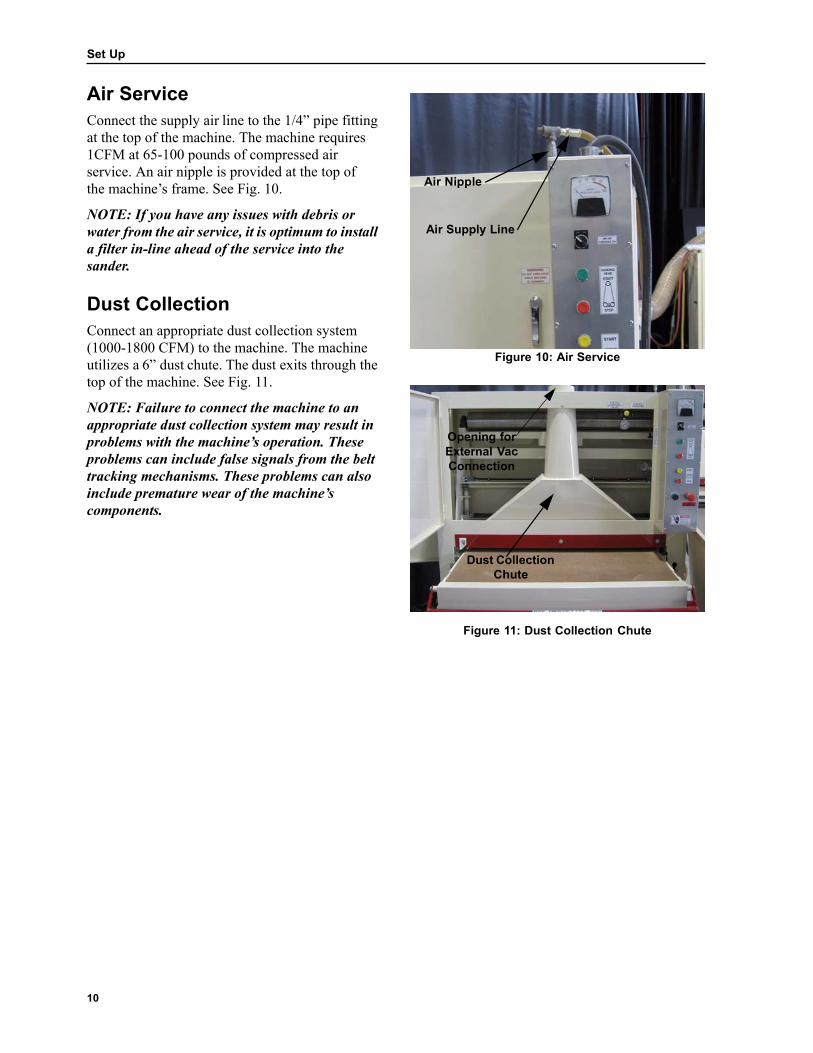
Air Service
Connect the supply air line to the 1/4” pipe fitting at the top of the machine. The machine requires 1CFM at 65-100 pounds of compressed air service. An air nipple is provided at the top of the machine’s frame. See Fig. 10.
NOTE: If you have any issues with debris or water from the air service, it is optimum to install a filter in-line ahead of the service into the sander. Dust Collection
Connect an appropriate dust collection system (1000-1800 CFM) to the machine. The machine utilizes a 6” dust chute. The dust exits through the top of the machine. See Fig. 11.
NOTE: Failure to connect the machine to an appropriate dust collection system may result in problems with the machine’s operation. These problems can include false signals from the belt tracking mechanisms. These problems can also include premature wear of the machine’s components.
Air Nipple
Air Supply Line
Figure 10: Air Service
Opening for External Vac Connection
Dust Collection
Chute
Figure 11: Dust Collection Chute

11
Introduction To The Components
Introduction
This chapter will describe, in detail, the individual components of the unit. It is required to review this chapter and have a good understanding of the machine components before operating your sander.
The Wide Belt Sander is controlled through the use of the miscellaneous buttons and switches on the front of the Control Panel. See Fig 12. The following pages will give a brief description of each item. Load Meter
The sander is equipped with a main motor load meter. See Fig. 13. The motor load is shown in a percentage basis on the meter. The machine should not be run when the pointer on the load meter is into the red band area (over 100%). You can reduce the load by slowing down the conveyor table speed, lowering the table, or raising or removing the platen. Air Control
The air control is located toward the top of the control panel. See Fig. 14. The toggle switch turns the air on and off. It is labeled “Air On Controls.” See Fig. 14. Leave the air switch in the “Off” position when the machine is not being used. See Fig. 14.
A single regulator regulates the air coming into the wide belt sander. The regulator is located inside the machine cabinet on the in-feed side. The regulator should be adjusted to between 60 and 65 psi of air pressure.* The machine is running at optimum operation at this adjustment. See Fig. 29 & 30. Page 15.
*High altitudes may require more air pressure for optimal operation.
Control Panel
Figure 12: Control Panel Load Meter
Figure 13: Load Meter Air Control
Air Control On/Off Switch
CAUTION: Never turn the air off until the sanding head has come to a complete stop.
Figure 14: Air Control

Introduction To The Components
12
Sanding Head Start Control
The “Start” Button is a green colored button labeled “Sanding Head Start.” See Fig. 15. The machine will not start if an emergency stop has been activated. It also will not start if there is not air pressure to the machine. You must completely read and understand this operator’s manual before operating the machine. Sanding Head Stop Control
Press the red colored button on the control panel to stop the sanding belt rotation during normal operating conditions. This button is labeled “Sanding Head Stop.” See Fig. 17. Pressing this button will turn off the sanding head and the conveyor table.
Control Panel Sanding Head
Start/Stop Label
Figure 15: Control Panel Green Start
Button
Sanding Head
Start/Stop Label
Figure 16: Green Start Button
Sanding Head Start/Stop Label
Red Stop
Button
Figure 17: Red Stop Button

Introduction To The Components
13
Emergency Stop Locations
There are multiple emergency stop systems in place on the machines. On the 43” x 75” belt sander there is one on the front of the table. See Fig. 19. On the 37” x 60” machine, this stop is located just above the opening to the sanding head on the cabinet. See Fig. 18. The other emergency stop on both machines is a mushroom-shaped button located on the front of the control panel. Use the stops located on the outside of the machine in any emergency situation where the machine needs to be stopped immediately.
There are also two emergency stops inside the cabinet that will automatically shut the machine down in the event that the abrasive sanding belt overtracks to the left or right hand side of the machine. See Fig. 20. Inside the belt loading door there is a safety switch which requires the door to be closed before operation. The other emergency stops must be pressed to shut the machine down.
There is also an emergency load cut off on 3 phase machines.
Emergency Stop Button
Emergency Stop Bar
Figure 18: 37” x 60” Belt Sander Emergency Stops
Emergency Stop Button
Emergency Stop Arm
Figure 19: 43” x 75” Belt Sander Emergency Stops
Emergency Stop Switch
Emergency Stop Switch
Figure 20: Automatic Emergency Stop Switches

Introduction To The Components
14
Conveyor Table Speed Adjustment Controls
Your machine is equipped with an electric DC motor with an adjustable feed speed. You can adjust the speed of the conveyor table from 0-18 feet per minute. This is accomplished by turning the black knob on the control panel. See Fig. 21 & 22. The conveyor belt speed adjustment knob is labeled with a 0-10 scale. Turn the knob clockwise (towards 10) for faster conveyor belt feed rate. Turn the knob counter-clockwise (towards 0) for slower conveyor belt feed rate.
Control Panel
Conveyor Table Speed Adjustment
Figure 21: Control Panel
Conveyor Table Speed Adjustment
Figure 22: Conveyor Table Speed Adjustment

Introduction To The Components
15
Conveyor Table Height Adjustment Gauges
There are two table height gauges included as standard equipment on the Safety Speed Cut Wide Belt Sanders. There is also one optional gauge available. See Fig. 25. The two standard height gauges are simple systems. One has a ruler with an indicator and the other is a simple stationary pointer. See Figs. 23 & 24. Utilizing the standard or optional gauges will help you get the most accurate, consistent and professional results from your sander. The points listed below address a description and explanation of the use of each of the table height gauges on the machine. Gauge With Ruler And Indicator
This gauge is positioned on the left-hand side (hand wheel side) of the machine. It is positioned vertically. There is a red colored indicator which points to your position on the ruler. This shows the table height in relationship to the contact roller. See Fig. 23. It is also used to indicate when you have reached your desired material thickness. This gauge is to be used in conjunction with a material thickness gauge. It is also used in conjunction with the second standardgauge on the machine, the stationary pointer.
Ruler Indicator
Figure 23: Gauge with Ruler and Indicator
Stationary Pointer
Figure 24: Stationary Table Height Gauge
Optional Gauge
Figure 25: Optional Table Height Digital Readout Gauge

Introduction To The Components
16
Simple Stationary Pointer
The simple stationary pointer is colored white and is located on the left side of the machine on the red safety bar. This is directly above the machine’s table. See Fig. 26. This pointer is used for quick setting of the table height according to your material thickness. To use this gauge, place your material down on the table and underneath the white tab. Adjust the table up or down until the highest point on your panel fits underneath the white stationary pointer. This will prepare you to sand without worrying about overloading the machine. This gauge is designed to make a quick, simple table height adjustment. Optional Digital Positioning Gauge System
The optional digital read out system utilizes a digital display to help you appropriately adjust the table height. See Fig. 27. This gauge measures the distance that you are raising or lowering the table, in relationship to the contact roller. You will also use it for measuring the actual dimension on your last (finishing) sanding passes. Refer to the operating and installation instructions included with the digital read out for more information on operating this gauge.
Stationary Pointer
Figure 26: Stationary Pointer
Figure 27: Optional Digital Read Out

Introduction To The Components
17
Air Valve #1 Air Valve #3
Figure 28: Air Valves and Regulator
Air Regulator
Air Valve #2
Abrasive Belt Tracking System
The machine is equipped with an air regulator. The regulator should be adjusted to approximately 60 to 65 psi. This is for all operations of the machine. The regulator can be adjusted by turning the yellow knob located on the front of the regulator. See Fig. 28.
There are two air valves that are located on the front door. See Fig. 28.
Valve No. 1 controls the air flow into the tracking piston. See Fig. 28. The tracking piston is located behind the control panel inside the machine’s cabinet. The amount of air flowing into the piston controls how quickly the swing idler roller tracks the sanding belt to the left side of the machine.
Valve No. 2 located inside the door controls the air flow into the tensioning piston. The tensioning piston pushes the swing arm idler roller up to tension the abrasive sanding belt. See Fig. 29.
Valve No. 3 controls the air flow out of the tracking piston. This controls how fast the swing arm roller tracks the abrasive sanding belt back to the right side of the machine toward the photoelectric eye. See Fig. 28.
ABRASIVE BELT TRACKING QUESTIONS ANSWERED
How does the tracking system work?
The abrasive sanding belt rides on three rollers. Two of the rollers are on the bottom and one roller is on the top of the machine. The one on the top steers the belt. From the factory, the top roller is just off from parallel with the bottom rollers. The right end of the roller is closer to the feed side of the machine. The left side is closer to the out feed side of the machine. The roller pivots in the middle. The right side of the machine is the electrical box side. The left side is the hand wheel side.
With the top roller set this way, the belt will track toward the eye. The tracking solonoid is turned on and off with the eye switch when the invisible light beam is broken by the abrasive sanding belt. The eye will energize the tracking solenoid valve when it is covered. The valve will open, letting air pass through it and into the tracking air piston.
Figure 29: Air Valve #2

Introduction To The Components
18
The piston comes out, it then pushes on the right side of the top roller moving that end of the roller closer to the out feed side of the machine. The belt will then track to the left side of the machine until the sanding belt clears the eye. When the eye is clear, the solenoid valve closes. Air pressure that is in the air piston will exhaust through the photoelectric eye, keeping the eye clear of sawdust.The piston will then be pulled back by spring pressure making the sanding belt track towards the right side again and beginning the cycle over.
NOTE: Under normal working conditions every time the eye gets covered, the tracking solenoid will open and close making a clicking sound. It is normal to hear multiple clicking sounds if the eye is being covered by an uneven belt edge. Adjustments must be made when there is not a clicking sound.

19
Sanding Operations
Operational Checklist
Before operating your unit, completely read and have a full understanding of this operator’s manual.
You should not operate your unit unless you have a full understanding of how the machine operates.
Before operating your machine, review the following steps.
1. Three-phase machines: Double-check the contact roller rotation and/or sand paper. Confirm that your sand paper is turning counter clockwise. See Fig. 31.
2. All access doors are to remain closed for operation.
3. Make sure all machine guards are bolted in place and the belt loading door is closed. See
Contact Roller
Should Turn
Counter- Clockwise
Belt Loading
Door
Fig. 32.
4. Adjust the conveyor table to the proper height for the thickness of the material you are sanding. Refer to the “Table Height Adjustment Gauges” page 15. Also shown in Fig. 33.
Before operating the machine, the operator must be familiar with the operating procedures of the machine. Do not operate the machine without
full knowledge and understanding of the steps in operating the unit.
Figure 31: Contact Roller Should Turn Counter-Clockwise
Machine Guard
Machine Guard
Machine Guard
Figure 32: Machine Guards
Table Height Adjustment
Figure 33: Table Height Adjustment
20
Sanding Operations
GRIT APPLICATIONS
36-40 GRIT
1. Use on rough lumber. 2. For heavy stock removal. 3. Abrasive sanding applications.
60 GRIT Use to remove adhesives. Use for dimensioning of already planed stock.
80 GRIT 1. Use for light dimensioning. 2. Use for general clean-up of stock. 3. Removes coarser grit sanding passes and/or planer marks.
100-120 GRIT
Use as an in-between belt to remove sanding marks from coarser grit sanding passes.
150-180 GRIT
Used for finishing passes.
220 GRIT
Use to remove cross-grain scratches.
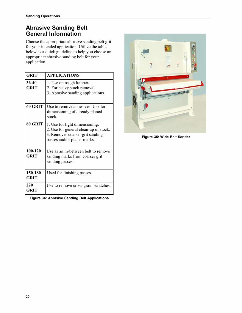
Abrasive Sanding Belt General Information
Choose the appropriate abrasive sanding belt grit for your intended application. Utilize the table below as a quick guideline to help you choose an appropriate abrasive sanding belt for your application.
Figure 35: Wide Belt Sander
Figure 34: Abrasive Sanding Belt Applications
21
Sanding Operations
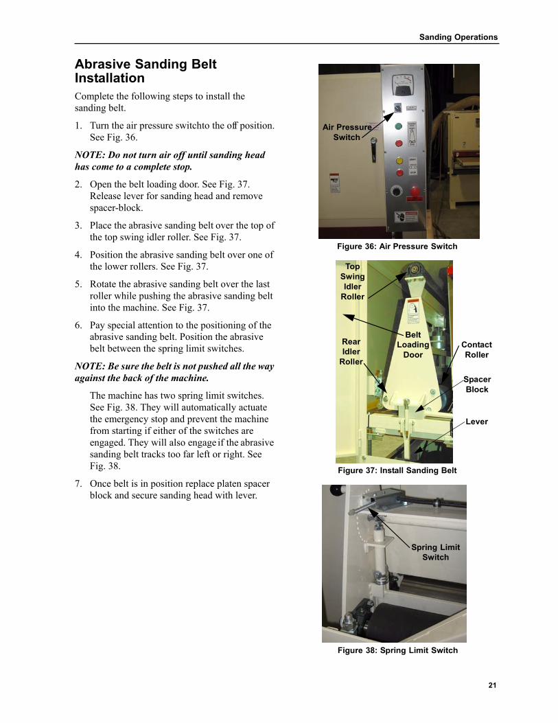
Abrasive Sanding Belt Installation
Complete the following steps to install the sanding belt.
1. Turn the air pressure switchto the off position. See Fig. 36.
NOTE: Do not turn air off until sanding head has come to a complete stop.
2. Open the belt loading door. See Fig. 37. Release lever for sanding head and remove spacer-block.
3. Place the abrasive sanding belt over the top of the top swing idler roller. See Fig. 37.
4. Position the abrasive sanding belt over one of the lower rollers. See Fig. 37.
5. Rotate the abrasive sanding belt over the last roller while pushing the abrasive sanding belt into the machine. See Fig. 37.
6. Pay special attention to the positioning of the abrasive sanding belt. Position the abrasive
Air Pressure
Switch
Figure 36: Air Pressure Switch
Top Swing Idler
Roller
Belt
belt between the spring limit switches.
NOTE: Be sure the belt is not pushed all the way against the back of the machine.
The machine has two spring limit switches. See Fig. 38. They will automatically actuate the emergency stop and prevent the machine from starting if either of the switches are engaged. They will also engage if the abrasive sanding belt tracks too far left or right. See
Rear Idler
Roller
Loading Door
Contact Roller
Spacer Block
Lever
Fig. 38.
7. Once belt is in position replace platen spacer block and secure sanding head with lever.
Figure 37: Install Sanding Belt
Spring Limit
Switch
Figure 38: Spring Limit Switch

22
Sanding Operations
Operating The Machine
Complete the following steps to operate the machine:
1. Measure the thickness of the material to be sanded. Adjust the table height adjustment handwheel. See Fig. 39. Adjust until the ruler indicator reads slightly less than the thickness of the material to be sanded. See Fig. 39.
Ruler
Indicator
Table Height Adjustment Handwheel
2. Turn the air pressure switch to the “On” position. See Fig. 40.
3. Press the green button labeled “Sanding Head Start.” See Fig. 40. The sanding head will then start. During this normal operation you will have a regular clicking sound. This is normal. When the abrasive sanding belt rotates in normal operation, it will pass back and forth, left to right across the electric eye. The eye will turn on the tracking solenoid. If the edge of the abrasive sanding belt should become frayed, it will click even more often. This is also normal.
4. Press the conveyor start button labeled “Conveyor Start.” This will start the conveyor belt turning. See Fig. 41.
Figure 39: Table Height Adjustment
Turn Air Pressure
Switch To On
Press Sanding Head Start Button
Figure 40: Air Pressure Switch and Sanding Head
Start Button
Press Conveyor
Start Button
Figure 41: Conveyor Start Button

23
Sanding Operations
5. Adjust the speed of the conveyor belt. Refer to the “conveyor belt speed adjustment” section on page 14. See Fig. 42.
6. Stand to one side or the other of the infeed table. Never stand directly inline with the table. Serious injury could occur in a kick-back situation.
7. Place the material onto the front end of the conveyor bed on the in-feed side of the machine. See Fig. 44. Your material will feed in the same direction as the conveyor table belt is rotating.
CAUTION: Do not place your fingers directly under the material. this could cause personal injury.
CAUTION: Never stand directly inline with the table. Serious injury could occur in a kick-back situation.
8. Feed your material into the machine. Keep an eye on the load meter. The load meter gauge measures the percentage of load on the motor when the material comes into contact with the platen.
Load Meter
The sander is equipped with a main motor load meter. See Fig. 13. The motor load is shown in a percentage basis on the meter. The machine should not be run when the pointer on the load meter is into the red band area (over 100%). You can reduce the load by slowing down the conveyor table speed, lowering the table, or raising or removing the platen.
Conveyor Belt Speed Knob
Figure 42: Conveyor Belt Speed
Table Height Adjustment Handwheel
Figure 43: Table Height Adjustment
Infeed Table
Stand To One Side Of The
Infeed Table
Figure 44: CAUTION: Never Stand Directly In Line With The Table Infeed Table. A Kick-back Situation
Could Cause Serious Injury.

24
Sanding Operations
9. It is important to use the full width of the abrasive sanding belt whenever possible. Feed the stock in alternating areas of the conveyor table to evenly wear the abrasive sanding belts. See Fig. 45. Feeding the stock into the machine in alternating areas of the conveyor table will also give longer life to the components of the machine such as the contact roller, conveyor belt and conveyor table.
10. On earlier sanding passes with coarser abrasive sanding belts, pieces can be fed into the machine at an angle up to 45 degrees. See Fig. 46. When sanding extra long pieces, start the pieces on one side of the conveyor belt. Angle them so the trailing end will exit the machine on the opposite side of the conveyor belt. This will use the whole width of the machine and the abrasive sanding belt. See Fig. 46.
11. When sanding with finer grits, or finishing sanding, to get best results, you need to run the piece straight through the sander in the direction of the grain. See Fig. 47. If you do not, sanding scratches may be more apparent on finished product.
Feed Stock In Alternating Areas Of Conveyor Belt To Evenly
Wear Belt.
Figure 45: Use Full Width Of Machine On Earlier Passes, With Coarse Grit - Feed Piece At An
Angle.
Figure 46: Angle Feed
Finish Passes Need To Feed Straight
Through
Figure 47: Straight Feed

25
Sanding Operations
Introduction To The Platen
The platen is used only for finish sanding.
NOTE: The platen is not designed for stock removal. Use the platen only for finish sanding. Stock removal should be completed first. See Fig. 48.
NOTE: All sanding marks should be removed with a medium grit belt before finish sanding with a platen.
NOTE: With the stock removal and sanding marks removal completed, you are now ready to
Platen
Platen
use the platen for finish sanding. Figure 48: Platen And Installation

26
Sanding Operations
37” X 60” Model Platen
The platen is removable on the 3760. The platen is not installed on the machine from the factory. Install the platen for the final finishing pass or two of 120 grit or finer belts.
Installing and Using the Platen:
1. Turn off machine by turning the air control to the “off” position.
NOTE: Do not turn air off until sanding belt has come to a comlete stop.
2. Open the belt loading door, loosen the sanding head lever and remove the spacer block. See Fig.49.
3. Slide the complete platen between the two bottom rollers on the platen support. See Fig. 49& 50.
4. Replace the spacer block and tighten the sanding head lever.
Spacer Block
Belt Loading
Door
5. After completing the finish sanding, remove the platen and store for future use. When not in use the platen should be stored in a dry clean area out the way of the operator.
Sanding Head Hold Down
Lever
Figure 49: Platen 37”x 60”
Platen
Figure 50: Remove Platen After Completing The Finish Sanding Step. 37”x 60” Only

27
Sanding Operations
4375 Series Models Platen
The platen is used only for finishing sanding. Complete the following steps for finish sanding on the Model 4375 with the platen:
1. Locate the platen adjustment system. It is located inside the belt loading door. See Fig. 51.
2. Locate the spring loaded adjusting knob. See Fig. 51. The spring loaded adjusting knob can be positioned in any of a series of holes in a half circle formation. See Fig. 51.
3. If the spring loaded adjusting knob is up (as shown in Fig. 51), the platen is up. If the adjusting knob is down, the platen is down. See Fig. 51.
4. The adjustment holes represent various positions for the platen. The adjustment holes enable the platen to have varying degrees of pressure against the material being sanded. The platen comes into contact with the abrasive belt around the middle hole (3:00 position) adjustment. The platen is adjustable up and down a full 1/8”.
5. Adjust the platen according to the desired position.
6. Feed your material into the machine keeping an eye on the load meter. The load meter gauge measures the percentage of load on the motor. The machine should not be run when the pointer on the load meter is into the red band area (over 100%). You can reduce the load by slowing down the conveyor table speed, lowering the table, or raising or removing the platen
7. Generally, table height adjustment is not recommended when the platen is in use. Sanding pressure should be solely controlled through the platen adjustment system.
Spring Loaded Adjusting Knob
Platen Adjustment
System
8. After completing the finish sanding, adjustthe spring loaded adjustment knob back to the 12 o’clock position to start using your contact roller again. See Fig. 51.
Figure 51: Platen Adjustment System - 43”x75” Only

28
Sanding Operations
4375 Platen Removal
To remove the platen, complete the following steps:
1. Lower the platen by turning the platen adjustment knob to the 6:00 position (43”x 75” only.)
2. Release sanding head hold down lever.
3. Remove the sanding spacer block. See Fig. 52.
4. Pull the platen out from the belt loading door. See Fig. 53.
The platen should be inspected periodically for wear. Refer to the platen maintenance instructions in the Maintenance Section.
Sanding
Head Hold Down Lever
Belt Loading
Door
Spacer Block
Figure 52: Platen
Platen
Figure 53: Remove Platen As Shown

29
Maintenance
Repairs
If repairs on your machine are needed beyond your capability, call Safety Speed at 800-772-2327. Safety Speed can provide technical advice or give you the name of a dealer near you who can service your machine.
WARNING: Always disconnect power to the machine before doing any maintenance.
WARNING: Always contact a qualified electrician for any electrical repairs.
Lubrication
The following areas should be lubricated. Sanding Head, Contact, and Idler Rollers
The sanding head, contact roller, and idler rollers are fitted with grease zerts. Grease the rollers every 20 hours of operation or once a month, whichever time frame is shorter. See Fig. 54 & 55.
Conveyor Table Rollers
The conveyor table rollers should be greased every three to four months.
Bronze Bushings
The bronze bushings are located on the jack screws, hand wheels (not shown) and at the ends of each of the two pinch rollers (not shown). Lubricate the bushings with motor oil every 30 days. See Fig. 56.
Jack Screws
The jack screws that support the conveyor belt should be cleaned with a solvent. The threads should be lubricated with a lithium based grease every 30 days or more often in harsher or heavy use environments. See Fig. 56.
Sanding Head Roller Grease Zert
Figure 54: Grease Zerts On Sanding Head Roller
Contact Roller Grease Zert
Rear Idler Roller
Figure 55: Grease Zerts On Contact Roller
Bronze Bushing Jack Screw
Figure 56: Jack Screw

30
Maintenance
Conveyor Drive Gear Reducer
The conveyor drive gear reducer is supplied with a life-time lubricant. See Fig. 57.
Swing Arm Top Idler Roller
The swing arm (top idler roller) has a pivot bushing. The bushing should be lubricated with motor oil every 30 days. See Fig. 58.
All Metal Moving Parts
As a general rule of thumb, the metal moving parts of the machine should be lubricated every 30 days.
Drive Motor Belt Tension
Check the tension of the drive motor belt, or belts, every 30 days. The tension can be adjusted by lowering the motor evenly. The belt(s) should only be as tight as needed to prevent the belt from slipping. See Fig. 59.
Figure 57: Conveyor Drive Gear Reducer
Swing Arm Bushing Swing Arm Top
Idler Roller
Figure 58: Swing Arm Top Idler Roller
Motor Drive Belt Tension
Figure 59: Drive Motor Belt Tension

31
Maintenance
Platen Graphite Replacement
The platen should be inspected periodically for wear. There are three main components to the platen:
1. The platen sleeve. See Fig. 61.
2. The platen graphite. See Fig. 61.
3. The platen felt. See Fig. 61.
Inspect the platen for wear marks that run through the graphite. If the graphite is worn through at any position, the graphite should be replaced with new graphite. Also inspect the white felt between the platen sleeve and the graphite. The white felt pad should have a consistent flat surface. If the surface is not consistent and flat, the felt should be
Platen
Felt
Figure 60: Platen
replaced. See Felt Replacement Instructions.
An irregular sanded surface will result from using bad graphite and/or felt.
To replace the platen graphite complete the following steps:
1. Remove the small fasteners that hold the graphite in place. See Fig. 61.
Not Shown (Under Graphite)
Sleeve
Graphite
2. Remove the graphite. See Fig. 61.
3. Inspect the white felt underneath the graphite for wear or uneven surface.
4. Replace the graphite and felt if necessary. See Fig. 61.
5. Reassemble and reinstall the platen into the wide belt sander when ready to use.
Fasteners
Figure 61: Platen Component

32
Maintenance
Platen Felt Replacement
The platen should be inspected periodically for wear. There are three main components to the platen:
1. The platen sleeve. See Fig. 63.
2. The platen graphite. See Fig. 63.
3. The platen felt. See Fig. 63.
Inspect the platen for wear marks that run through the graphite. If the graphite is worn through at any position, the graphite should be replaced with a new graphite. Also inspect the white felt between the platen sleeve and the graphite. The white felt
Platen
Graphite Figure 62: Felt and Graphite
pad should have a consistent flat surface. If the surface is not consistent and flat, the felt should be replaced. See Felt Replacement Instructions.
An irregular sanded surface will result from using bad graphite and/or felt.
To replace the platen felt complete the following steps:
1. Remove the small fasteners that hold the
Felt Not Shown
Graphite
Fasteners
platen graphite in place. See Fig. 63.
2. Remove the graphite. See Fig. 63.
3. Remove the felt and replace with a new felt. See Fig. 63.
4. Reinstall or replace the graphite. See Fig. 63.
5. Reassemble and reinstall the platen into the wide belt sander. See Fig. 63.
Figure 63: Graphite Platen Cover

33
Maintenance
Contact Roller Resurfacing
The conveyor table and the contact roller must be exactly parallel with each other. If they are not exactly parallel, the contact roller will wear unevenly into a cone shaped surface.
If uneven wear has not yet occurred refer to the conveyor table leveling procedures in this manual.
If wear has occurred or if rubber is pitted or grooved producing wavy marks in material, it may be necessary to resurface the contact roller.
To resurface the contact roller complete the following steps.
1. Locate a piece of furniture grade particle board or another very flat consistent substrate.
2. Cut it to 18” x 38” for the 37” x 60” model sander or 18” x 44” forthe 4375 model sander.
3. Adhere a 60 or 80 grit abrasive sanding belt to the panel, preferably a silicon carbide mineral abrasive.
4. Remove the abrasive sanding belt from the sander.
Lower the table height until no material would be removed on a pass.
5. Press the sanding head start button. See Fig. 65.
6. Press the conveyor start button. See Fig. 65.
7. Adjust the table height so you will remove a minimal amount of rubber from roller.
8. Run the sanding board through the machine. Remove a minimal amount of rubber on each pass until you have removed the defect in the roller.
NOTE: It is important to adjust the conveyor bed height so the sanding board will just barely come into contact with the contact roller. You must remove a minimal amount of rubber from the roller on each pass. By making these very light passes, you will minimize heat and loading of the abrasive.
After resurfacing your contact roller it may be necessary to adjust the machine’s pinch rollers and the rear idler roller. Refer to pinch rollers and rear idler roller adjustments on page 36.
Contact Roller
Figure 64: Contact Roller
Sanding Head Start Button
Conveyor Start
Button
Figure 65: Control Panel

34
Maintenance
Contact Roller Removal/Replacement
To remove the contact roller complete the following steps:
1. Remove the bolt on door on the side of the machine.
2. Remove the drive pulley. This is accomplished by unscrewing the three 1/4” bolts from the hub. Then screw them into the other threaded holes on the hub. See Fig. 66.
3. Unbolt and remove the dust collection chute from the inside of the cabinet. See Fig. 67.
4. Remove the housing bolts from the two bearings on the ends of the contact roller. See Fig. 68.
5. Remove the contact roller. See Fig. 68.
Complete the following steps to remove the contact roller bearing.
1. Loosen and remove the set screws from the bearing. Loc Tite has been used to cement them in place.
Drive Pulley
Figure 66: Remove Drive Pulley
Unbolt Dust Collection Chute
Figure 67: Remove Dust Chute Bearing Cast
2. The bearings have also been cemented with Loc Tite.
3. Pull the bearings off using a gear puller.
CAUTION: Do not grab the cast housing of the bearing with the gear puller. It may cause damage to the bearing or the bearing’s cast housing.
Housing Set Screws
Contact Roller
I
Contact Roller Bearings
Figure 68: Remove Contact Roller

35
Maintenance
Contact Roller Reinstallation
To reinstall the contact roller complete the following steps:
1. Clean the roller shafts with a solvent such as rubbing alcohol or paint thinner.
2. Clean the inside of the bearing’s set screw holes with solvent.
3. Slide the left and right bearings onto the shaft.
4. Install contact roller and bolts starting from right to left.
5. Adjust the contact roller so it measures 2” from the right side wall to the end of the rubber. See Fig. 71. Apply a few drops of Loc Tite to each set screw of the shaft.
Re-leveling The Contact Roller
It is recommended to use a dial indicator to level the roller. If a dial indicator is not available you can use a steel ruler.
To level the contact roller use the same size metal spacers, as shown in Fig. 70, and complete the following steps:
1. Place the metal spacers under the roller, on top of the table. See Fig. 70.
NOTE: You may also need to roll back the side of the conveyor belt to expose the steel table by loosening the tensioning bolts and then wrapping something around the belts and pulling tight.
2. Slide the bars under the roller and compare the friction from the right to the left.
3. Loosen the bearing bolts. Slide the roller up or down until it is parallel with the conveyor table.
4. Re-tighten bolts.
5. Reinstall the drive pulley and side cover.
Contact Roller
Figure 69: Contact Roller
Figure 70: Two Metal Spacers
Bearing Bolts
Contact Roller
Spacing is 2”
Figure 71: Bearing Bolts

36
Maintenance
6. Lower the front pinch roller back in place. The pinch roller should go up anddown about 1/64 inch - 1/32 inch when material passes under it.
Pinch Roller and Idler Roller Replacement
These rollers are positioned parallel to the contact roller. The pinch rollers (one on the in-feed and one on the out-feed) are to be adjusted 1/16” lower than the contact roller. The rear idler roller (steel roller behind the contact roller) is to be positioned 1/16” higher than the contact roller.
The idler roller replacement instructions are very similar to the contact roller re-installation on the previous page. Refer to this section for replacement of the idler roller. See Figures 72, 73, and 74.
Idler Roller
Figure 72: Idler Roller
Figure 73: Metal Spacers
Idler Roller
Figure 74: Idler Roller

37
Maintenance
Rear Idler Roller Leveling
To level the rear idler roller complete the following steps:
1. Place two metal spacers of equal height on the conveyor table under both rollers. Figure 75.
2. Raise the table until the material just comes into contact with the contact roller.
3. Loosen the bearing housings on the ends of the rear idler roller.
4. Place spacers on material under steel roller, lifting it about 1/16” above the bottom of the contact roller.
Level The Table
To level the table complete the following steps.
1. Cut a board in half.
2. Send the two boards through the machine sanding both of them at the same time, one board on the right side and the other board on the left side. See Fig 76.
3. Measure the two pieces with a micrometer or a dial calliper. If the table is level thetwo pieces should measure the same exact thickness.
If they do not measure the same complete the following steps to level the conveyor table.
Figure 75: Two Spacers Under Roller
Figure 76: Send two boards through machine.

38
Maintenance
Level The Conveyor Table
Complete the following steps to level the conveyor table.
1. Remove the bottom guards.
2. Place shims under the jack screw bearings on the low side of the table. Figure 77.
NOTE: This is a two-person job.
3. Pry up the bearing using two screwdrivers, one from each side. The other person then slides the shim under the bearing.
4. Check the table for corner rock.
5. Lift each corner of the table up and down. The table should be sitting on all four jack screws evenly.
6. Add additional shims as necessary to level the
Jack Screw
Bearing
conveyor table. Figure 77: Jack Screw

39
Maintenance
Wide Belt Sander Belt Tracking
If the belt is tracking too far one-way or not tracking at all.
Was the belt recently changed? Different grit, manufacturer, backing, weight and construction can effect how the belt tracks.
Check to see if any adjustments have recently been made to the machine, if the #1 or #3 valves have been adjusted to obtain correct belt oscillation.
If the tracking piston needs to extend out faster open (loosen) the #1 valve, if it needs to extend slower the #1 valve needs to be closed (tighten). If the piston needs to retract faster open (loosen) the #3 valve, if it needs to retract slower close (tighten) the #3 valve. The tracking piston should always be moving in or out to achieve correct oscillation. If the conveyer is tracking too far in one direction, the tracking screws need to be adjusted.
If the belt will not or is continuously 1. If the belt is tracking too far to the right. tracking to the right: (Reverse the sides if tracking too far to the
1. The first thing to do is to make sure the photo eye, and photo eye reflector are free of debris. Wipe off both the eye and reflector.
2. Check to see if the photo eye is working, to do this remove the belt, and turn the machines air on. If the tracking piston is protruded it can mean two things; either the photo eye does not work or it is not aimed at the reflector, make sure the eye is aimed at the reflector and that the reflector is clean. (Make sure that the motor is OFF) Next, check if the photo eye solenoid is working. To do this turn the air to the machine on and cover the photo eye with something. If the solenoid is working properly the solenoid will make a (clicking) noise and the tracking piston shaft will extend outward. If nothing happens it can mean the solenoid may not work.
If the belt will not or is continuously tracking to the left:
3. The first thing to do is to make sure the photo eye, and photo eye reflector is free of debris. Wipe off both the eye and reflector.
4. Verify the rotation of the sanding belt. It should be turning counter clockwise if looking at it from the loading door. If it is turning clockwise flip the two low leg wires around on the three-phase motor.
left.)
a. Loosen the left tension screw exactly 5 turns. (Has to be exact, before starting to turn note where the wrench is.)
b. When the belt tracks back to the middle, tighten the left tension screw exactly 5 turns.
Tighten the right tension screw 1/4 turn and watch the belt for 5 minutes. After the 5 minutes adjust accordingly, but only tighten or loosen a maximum of a 1/4 turn at a time and watch for 5 minutes in between each adjustment. Do not over tighten the bolts, if needed loosen the other side. Over tightening can cause stress on conveyer belt, stripping of the screws, or destruction of the conveyer.

40
Maintenance
This page was intentionally left blank.

41
Trouble Shooting
TROUBLE SHOOTING
PROBLEM CAUSE SOLUTION
Machine will not start
The machine is equipped with an air cut-out switch. It will prevent the machine from starting if there is not enough air pressure to run the machine.
1. Check for correct air pressure.
2. Check all Emergency Stop switches, one may be tripped.
3. Check power disconnect.
The sanding belt limit switch is bent or stuck inthe “on” position.
You should hear a faint click from the switch whenthe switch is moved to the left or right. If you do not hear a faint click, the arm is bent and needs to be straightened. A small screwdriver is recommended to bend the switch back into shape.
Unwanted surface marks.
1. After a board has been sanded, you might see chatter, ripple or washboard marks on the surface of the board. NOTE: This might not be apparent until after a board has been finished.
2. This can happen if the
settings for the conveyor belt have been adjusted. Example: The four dials inside the control box
3. This can also happen when the conveyor belt is loose on the table due to stretching. The tensioning bolts must be tightened.
1. To prevent these marks, lower the platen. When the platen is lowered it will sand less per pass and should give you the smooth finish needed.
NOTE: Passing the material through the machine twice in the finishing sanding process is recommended for eliminating unwanted surface marks. If the marks are still there, run your conveyor belt slower. This will allow more time for your abrasive sanding to remove the marks.
2. Readjust the four converyor belt dials inside the control box. The conveyor low voltage control board is on the right hand side inside the control panel. The four white dials should read from the back of machine to front as follows: 10:00, 11:00, 3:00, and 10:30 respectively.
3. Tighten the conveyor belt tensioning bolts. See page 39.
42
Trouble Shooting
PROBLEM CAUSE SOLUTION
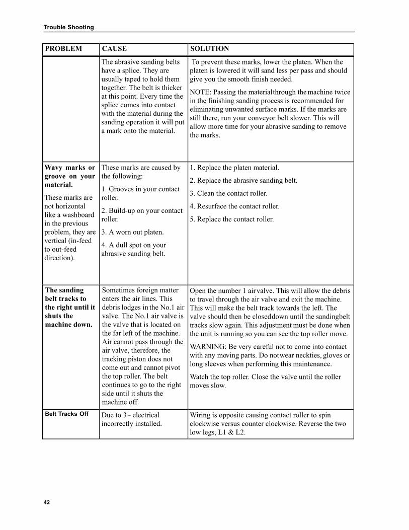
The abrasive sanding belts have a splice. They are usually taped to hold them together. The belt is thicker at this point. Every time the splice comes into contact with the material during the sanding operation it will put a mark onto the material.
To prevent these marks, lower the platen. When the platen is lowered it will sand less per pass and should give you the smooth finish needed.
NOTE: Passing the materialthrough the machine twice in the finishing sanding process is recommended for eliminating unwanted surface marks. If the marks are still there, run your conveyor belt slower. This will allow more time for your abrasive sanding to remove the marks.
Wavy marks or groove on your material.
These marks are not horizontal like a washboard in the previous problem, they are vertical (in-feed to out-feed direction).
These marks are caused by the following:
1. Grooves in your contact roller.
2. Build-up on your contact roller.
3. A worn out platen.
4. A dull spot on your abrasive sanding belt.
1. Replace the platen material.
2. Replace the abrasive sanding belt.
3. Clean the contact roller.
4. Resurface the contact roller.
5. Replace the contact roller.
The sanding belt tracks to the right until it shuts the machine down.
Sometimes foreign matter enters the air lines. This debris lodges in the No.1 air valve. The No.1 air valve is the valve that is located on the far left of the machine. Air cannot pass through the air valve, therefore, the tracking piston does not come out and cannot pivot the top roller. The belt continues to go to the right side until it shuts the machine off.
Open the number 1 air valve. This will allow the debris to travel through the air valve and exit the machine. This will make the belt track towards the left. The valve should then be closed down until the sandingbelt tracks slow again. This adjustment must be done when the unit is running so you can see the top roller move.
WARNING: Be very careful not to come into contact with any moving parts. Do not wear neckties, gloves or long sleeves when performing this maintenance.
Watch the top roller. Close the valve until the roller moves slow.
Belt Tracks Off Due to 3~ electrical incorrectly installed.
Wiring is opposite causing contact roller to spin clockwise versus counter clockwise. Reverse the two low legs, L1 & L2.

43
Trouble Shooting
PROBLEM CAUSE SOLUTION
The belt still tracks to the right.
The solenoid valve is not working properly or the electric eye is not working.
The electric photo eye light beam is not hitting the reflector.
.
1. Remove the right side cover, exposing the tensioning piston and top roller.
2. Remove the back door on the model 3760 or 4375.
3. Turn the air control to the “on” position. Remove the abrasive sanding belt. With the motor in the “off” position, place your hand in between the reflector and the eye. This will block the invisible beam.
Check to see if tracking piston is extended. If it is, then that means that there is something wrong with the eye. (Example: fake signal, misaligned, dirty)
You should hear the solenoid click on and off. If you do not, either the eye’s invisible light beam is not getting to and from the reflector or the solanoid valve is not working or the eye is not working.
Check if the light beam is hitting the reflector. Complete the following steps to ensure the light beam is hitting the reflector:
Place a reflective surface against the lense of the photoeye. If there is still no clicking heard and piston action seen, move the reflector in front of the eye. If the eye is bador the solanoid is bad, test both with a volt meter or 110 volt test light. ONLY A LICENSED ELECTRICAN SHOULD COMPLETE THE FOLLOWING TEST.
1. Disconnect power from the machine. Remove the electrical box cover. Place a screw in one corner of the cover with the cover back facing towards you. Screw the cover corner to the electrical box corner facing the rear.
2. Reconnect power to the machine.
CAUTION: Do not touch any bare wires with hands or any un-insulated tools. Serious electrical shock may occur.

Trouble Shooting
44
PROBLEM CAUSE SOLUTION
Sanding belt tracks to the left.
Foreign matter can get into the air line. The debris moves around and lodges in the air valve. Thisblocks the air flow from the belt tracking piston. Without air exhausting from the tracking piston, the piston will stay out. The belt will continue to track to the left side of the machine until it hits the safety switch. This shuts down the machine.
Open the No. 3 air valve a turn or two. Foreign matter will move through the air valve and exit the machine. This will allow the air to escape from the air piston. This allows the piston to move back. The sanding belt will then track towards the right side of the machine again. With the air valve open this much, the belt will track back to the right very fast. The valve then has to be closed down until the sanding belt tracks slow again. This adjustment must be done when the machine is running.
WARNING: Be very careful not to come in contact with any moving parts. Do not wear neck ties, gloves or long sleeves. Serious injury could result.
If the belt continues to track to the left, make sure it is going in the opposite direction of the material that is feeding into the machine. In other words, the rubber contact roller should be turning counter-clockwise when looking at it from the belt loading door. See Page40.
The sanding belt tracks perfectly without any load, but does not track perfectly when sanding material.
The bottom rollers are not parallel with each other.
Leave the rubber contact roller in place. Adjust the rear steel idler roller. See Page 36 and 37.

45
Key Part
Number
Description
1. WB613 Left Side Door
2. WB638
WB544
WB516-43
WB109
WB54
Table Lift Assembly:
Table Wheel Handle
Table Lift Handle
Handle Support Plate
(2) Bushings
Bevel Gear
3. WB607 Left Lower Panel
4. WB622 Ruler Indicator
5. WB131 Front Table Roller
6. Belt Tension Adjust Bolt
7. WB132 Rear Table Roller
8. WB658 (2) Rear Table Roller Bearings
9. WB624 Left Side Table Guard
10. WB621 Curved Guard
11. WB662
WB663
Door Handle
Door Latch
4375 Exploded View & Parts List
A. 9 6 1
1 11 4
5
2 2
6
9
3 5
Figure 80
Figure 78 7
8
3 7 10
4 8
Figure 81
Figure 79
Key Part Number
Description
1. WB612 Front Guard
2. WB626
WB513
Front Face Plate
Height Indicator
3. WB611 Conveyor Guard
4. WB651 E-Stop Handle
5. WB616 Front Lower Panel
6. WB660 Control Panel Cover
7. WB36B Gummy Belt
8. WB610 Table
9. WB662
WB663
Door Handle
Door Latch

4375 Exploded View & Parts List
46
Key Part Number
Description
1. WB614 Rear Panel
2. WB616 Lower Rear Panel
3. WB608 Top Cover Panel
1 1
2
5
3 8
2
4
6
Figure 84
Figure 82
3
7 Figure 85
Figure 83
Key Part Number
Description
1. WB615 Right Side Panel
2. WB101 DC Motor
3. WB102
WB79
WB38
WB539-43
Gear Reducer
Roller Gear (30 tooth)
Reducer Gear (15 tooth)
Reducer Chain
4. WB705 Lower Reducer Guard
5. WB668 E-Stop Rod
Spring
(5) Washers
(2) Cotter Pins
6. WB69 E-Stop Switch
7. WB704 Upper Reducer Guard
8. WB510 E-Stop bushing

4375 Exploded View & Parts List
47
Key Part Number
Description
1. WB128 Swing Arm Roller
2. WB135
WB659
Left Swing Arm Bearing
Swing Arm Block
3. WB618 Swing Arm
4. WB 68
WB115LH
WB76
Left Limit Switch:
Limit Switch
Left Limit Switch Cover
Limit Switch Spring
5. WB112 Left Contact Roller Bearing
6. Right Limit Switch (see Figure 87 Key #6)
7. WB129 Contact Roller
8. WB100 Right Contact Roller Bearing
9. WB628 Swing Arm Busing Bracket
10. WB545 Swing Arm Shaft Bushing
11. WB200-43 Tension Piston
12. WB658 Right Swing Arm Bearing
13. WB15 Air Regulator
1 2 1 13
2 12
6
3
7 4
Figure 86
4
5
8
5
Figure 88
3
6
9 7
10 8
11
9
10
Figure 89
Figure 87
Key Part Number
Description
1. WB617 Dust Vent
2. WB16 Pressure Gauge
3. WB14 Photo Eye
4. WB623
WB105C
Photo Eye Holder
1/4 x 1/4 NPT, 90
5. WB543 Photo Eye Reflector
6.
WB68
WB115RH
Right Limit Switch:
Limit Switch
Right Limit Switch Cover
7. WB76 Limit Switch Spring
8. WB605 Platen Shaft
9. WB634 Platen Holder
10. WB89 (2)Platen Spring

4375 Exploded View & Parts List
48
Key Part Number
Description
1. WB658 Right Idler Roller Bearing
2. WB137 Rear, Right Pinch Roller Bracket
3. WB642
WB110
Rear, Right Jackscrew Cap
Jackscrew Cap Bushing
4. WB127 Idler Roller
5. WB658 Left Idler Roller Bearing
6. WB130 Pinch Roller
7. WB137 Rear, Left Pinch Roller Bracket (Bracket Flipped)
8. WB640
WB110
Rear, Left Jackscrew cap
Jackscrew Cap Bushing
9. WB719 Rear, Right Jackscrew
10. WB40 Jackscrew Bearing
11. WB719 Rear, Left Jackscrew
12. WB40 Jackscrew Bearing
1
4
1
2 5
2
6
7
3 3 8
Figure 92
Figure 90
9
11 4
10
5 12
Figure 93
Figure 91
Key Part Number
Description
1. WB112 Left Contact Roller Bearing
2. WB137 Front, Left Pinch Roller Bracket
3. WB130 Pinch Roller
4. WB100 Right Contact Roller Bearing
5. WB137 Front, Right Pinch Roller Bracket
6. WB129 Contact Roller
WB133 Contact Roller Kit
6

4375 Exploded View & Parts List
49
Key Part Number
Description
1. WB74 (3) Swing Arm Spring
2. WB202 Swing Arm Piston
9 10
5 1 1
4 2
2 3
Figure 94 6
Figure 95
7
8 Figure 97
11
12
Figure 96
Key Part
Number Description
1. WB719
WB53
Front, Left Jackscrew With Bevel Gear
2. WB40 Jackscrew Bearing
3. WB538-43 Table Chain
4. WB719 Front, Right Jackscrew
5. WB40 Jackscrew Bearing
6. WB62
WB65
WB66
Sander Motor - 10 HP
Sander Motor - 20 HP
Sander Motor - 30 HP
7. WB52 Idler Gear
8. WB629 Chain Adjustment Bracket
9. WB641
WB110
Front, Left Jackscrew Cap
Jackscrew Cap Bushing
10. WB643
WB110
Front, Right Jackscrew Cap
Jackscrew Cap Bushing
11. WB23 (4) Table Bushing
12. WB528 (4) Jackscrew Nut

4375 Exploded View & Parts List
50
Key Part Number
Description
1. WB108
WB106
WB106
Roller Bushing - 10 HP
Roller Bushing - 20 HP
Roller Bushing - 30 HP
2. WB104
WB656
WB547
Roller Pulley - 10 HP
Roller Pulley - 20 HP
Roller Pulley - 30 HP
3. WB541 Brake Block Wood
4. WB201 Brake Piston
5. WB657
WB654
WB654
(2) Belts - 10 HP
(3) Belts - 20 HP
(4) Belts - 30 HP
6. WB103
WB655
WB548
Motor Pulley - 10 HP
Motor Pulley - 20 HP
Motor Pulley - 30 HP
7. WB107
WB113
WB550
Motor Bushing - 10 HP
Motor Bushing - 20 HP
Motor Bushing - 30 HP
1 2 1 16
3 2 9
10 4
3
5
4 11
6
5 12
7 13
6
14
Figure 98 7
8 15
Figure 99
Key Part Number
Description
1. WB18 Low Air
2. WB540 Ground Bar
3. Neutral and Hot Bar
4. WB17 Main Contact
5. WB556
WB557
Fuse Holder
Fuse
6. WB98 Current Transformer
7. WB11 Brake Contact
8. WB11 Table Contact
9. WB77 N/O Contact Block/Bracket
10. WB77
WB111
N/O Contact Block/Bracket
N/C Contact Block Only
11. WB95 N/C Contact Block/Bracket
12. WB77 N/O Contact Block/Bracket
13. WB95 N/C Contact Block/Bracket
14. WB13 DC Drive Variable Speed Controller
15. WB95
WB96
N/C Contact Block/Bracket
N/O Contact Block Only
16. WB652 Inside Electrical Panel

4375 Exploded View & Parts List
51
Key Part Number
Description
1. PS516 Air Hose
2. WB105A 1/4 x 1/4 NPT, strait
3. WB 703 Air Fitting, Female
4. WB12
WB105C
#1 Solenoid
Solenoid
1/4 x 1/4 NPT, 90
Long Threaded Tube
5. WB12
WB105C WB105E
#2 Solenoid
Solenoid
(2) 1/4 x 1/4 NPT, 90
Threaded Tube
1/4 x 1/8 Flow Control Valve
6. WB12
WB105C
#3 Solenoid
Solenoid
(2) 1/4 x 1/4 NPT, 90
7. WB105E (2) 1/4 x 1/8 Flow Control Valve
8. WB105D (2) 1/4 Tube Tee
9. WB105F 1/4 x 1/8, 90
8 3
8 4 1
9 2
1 5
7
2 6
3
4
5 Figure 101
6
7
9
Figure 100
Key Part Number
Description
1. WB78 On/Off Legend Air
2. WB93 On/Off Switch Air
3. WB90 Push Button, Green
4. WB91 Push Button, Red
5. WB92 Push Button, Yellow
6. WB91 Push Button, Red
7. WB13 Conveyor Feed Rate Adjustment Switch
8. WB67 Load Meter
9. WB84 E-Stop Mushroom Switch

4375 Exploded View & Parts List
52
3
1
2
Figure 102
Key Part Number
Description
1. WB713
WB627
WB34
WB31
Platen Kit Complete
Platen Holder, Galvanized
1005 Pressed White Felt, 43”
Platen Graphite
2. WB637 Hold Down Clamp
3. WB666
WB72
Platen Adjustment Pin
Platen Pin Spring
4. WB138 Safety Switch
5. WB710 Safety Switch Bracket
6. WB139 Door Key
46
5

53
3760 Exploded View & Parts List
Key Part Number
Description
1. WB67 Load Meter
2. WB93
WB78
On/Off Air Switch
On/Off Legend
3. WB90 Push Button Knob, Green
4. WB91 Push Button Knob, Red
5. WB92 Push Button Knob, Yellow
6. WB91 Push Button Knob, Red
7. WB13 Conveyor Feed Rate Adjustment Switch (See DC Switch Board)
8. WB94 Red Mushroom E-Stop
9. WB508 Dust Chute
10. WB506 Top Panel
11. WB105 Quick Air Connect, Male
12. Clamp (Main Power) Supply Entry
3760 Exploded View & Parts List
13 6 1
1 2
4
5 3
4 3
5
2
6
7 8
Figure 103
10 12
11 9
7 8 10
9
Figure 104
Figure 105
11
12
Figure 106
Key Part Number
Description
1. WB502 Front Upper Panel
2. WB505 Front Lower Panel
3. WB534 Control Panel
4. WB518
WB513
E-Stop Bar
Height Indicator
5. WB140 Pressure Gauge
6. WB15 Air Regulator
7. WB511 Front Table Guard
8. WB36 Gummy Belt
9. WB83 Front Table Roller
10.
WB531
Table Height Indicator:
Ruler Indicator
8 1/2” Ruler
11. WB507 Table
12. WB75 E-Stop Spring (Behind Bar)
13. WB105E (2) Flow Control Valves (Air Adjustments Valves)

54
3760 Exploded View & Parts List
Key Part Number
Description
1. WB542 Door Handle
2. WB501 Left Side Door Panel
3. WB85
WB40
Rear Table Roller
(2) Rear Roller Bearing (Both Sides)
4. WB504 Lower Left Side Panel
5. Table Tension Bolt (7/16 - 14 x 4, grade 5)
6.
WB516
WB544
WB10
WB109
WB54
Table Lift Handle:
Handle Support Plate
Handle Grip
Wheel Handle (2)
Bushings Handle
Bevel Gear
1
1
2 2
3
3
5
4 5
6
Figure 107 Figure 108
4
Figure 109
Key Part Number
Description
1. WB500 Right Side Panel
2. WB60 DC Motor
3. WB61
WB56
WB51
WB539
Reducer
Conveyor Gear (21 tooth)
Roller Gear (12 tooth)
Conveyor Chain
4. WB536 Reducer Guard
5. WB69 E-Stop Switch

55
3760 Exploded View & Parts List
Key Part Number
Description
1. WB503 Rear Top Panel
2. WB505 Rear, Lower Panel
1 3 4
2 5
1 6
7
Figure 111
2
9
Figure 110
8
Figure 112
Key Part Number
Description
1. WB543 Photo Eye Reflector
2. WB537 Photo Eye Holder
3. WB105C 1/4 x 1/4 NPT, 90
4. WB14 Photo Eye
5. WB68
WB115- RH
Limit Switch (right)
Limit Switch
Limit Switch Cover RH
6. WB76 Limit Switch Spring
7. WB519 Wire Strap
8. WB710
Door Safety Switch
Door Switch Bracket
9. WB508 Dust Chute

56
3760 Exploded View & Parts List
Key Part Number
Description
1. WB43 Right Contact Roller Bearing
2. WB80 Contact Roller
WB522 Contact Roller Kit
3. WB137 Front, Right Pinch Roller Bracket
4. WB81 Front Pinch Roller
5. WB137 Front, Left Pinch Roller Bracket
2 1
1 3 3
4
4
5 2
9 10
Figure 113
Figure 115
6
6
5
7 2
8
Figure 116
Figure 114
Key Part Number
Description
1. WB82 Swing Arm Roller
2. WB44 Left Swing Arm Bearing
3. WB521 Swing Arm
4.
WB68
WB115LH
WB76
Left Limit Switch:
Limit Switch
Left Limit Switch Bracket
Limit Switch Spring
5. WB530 Platen Holder
6. WB535 Swing Arm Bushing Bracket
7. WB23 Swing Arm Bushing
8. WB200 Tension Piston
9. WB525 Front, Left Jackscrew Cap
10. WB524 Front, Right Jackscrew Cap

57
3760 Exploded View & Parts List
Key Part Number
Description
1. WB84 Idler Bottom Roller
2. WB41 (2) Contact Roller Bearings (Both Sides)
3. WB137 Rear, Right Pinch Roller Bracket
4. WB253 Rear, Right Jackscrew Cap
5. WB81 Pinch Roller (Not Shown in Photo)
6. WB137 Rear, Left Pinch Roller Bracket
7. WB517 Rear, Left Jackscrew Cap
8. WB515 Rear, Right Jackscrew
9. WB41 Rear, Right Jackscrew Bearing
10. WB515 Rear, Left Jackscrew
11. WB41 Rear, Left Jackscrew Bearing
12. WB41 Right Swing Arm Bearing
1 4
12 5
1 5 6
2
2 3 6
4 7 3
Figure 117 Figure 119
8
9
Figure 118
10
8
11 7
Figure 120
9 10
Figure 121
Key Part Number
Description
1. WB515 Front, Left Jackscrew W/ 30 Tooth Bevel Gear
2. WB53 DC Front, Left Jackscrew Bearing
3. WB538
PS862
Table Chain
Master Link
4. WB515 Front, Right Jackscrew
5. WB41 Front, Right Jackscrew Bearing
6. WB62
WB64
10 HP Motor - 10 HP
15 HP Motor - 15 HP
7. WB52 Idler Gear
8. WB629 Chain Adjustment Bracket
9. WB22 (4) Jackscrew Nut Bushing
10. WB118 (4) Jackscrew Nut

58
3760 Exploded View & Parts List
Key Part Number
Description
1. WB540 Ground Bar
2. Neutral and Hot Bar
3. WB17 Main Contact
4. WB19 Thermal Overload - 15 HP
5. WB98 Current Transformer
6. WB11 Brake Contact
7. WB11 Table Contact
8. WB77 N/O Contact Block/Bracket
9. WB77
WB111
N/O Contact Block/Bracket
N/C Contact Block Only
10. WB95 N/C Contact Block/Bracket
11. WB77 N/O Contact Block Bracket
12. WB95 N/C Contact Block Bracket
13. WB13 DC Drive Variable Speed Controller
14. WB95
WB96
N/C Contact Block Bracket
N/O Contact Block Only
15. WB18 Low Air
16. WB652 Inside Electrical Panel
17. WB557
WB556
Fuse
Fuse Holder
15 1 1
8 2
2 9
10
3
11
4
17 12 3
5 4
13
6
7 14 5
16
Figure 122
Figure 123
6 7
8 9
Figure 124
Key Part
NumberDescription
1. WB74 (3) Swing Arm Springs
2. WB202 Swing Arm Piston
3. WB57
WB104
Roller Pulley - 10 HP
Roller Pulley - 15 HP
4. WB46
WB107
Roller Bushing - 10 HP
Roller Bushing - 15 HP
5. WB50
WB134
Belt - 10 HP
(2) Belts - 15 HP
6. WB541 Brake Block, Wood
7. WB201 Brake Piston
8. WB47
WB103
Motor Pulley - 10 HP
Motor Pulley - 15 HP
9. WB46
WB108
Motor Bushing - 10 HP
Motor Bushing - 15 HP
59
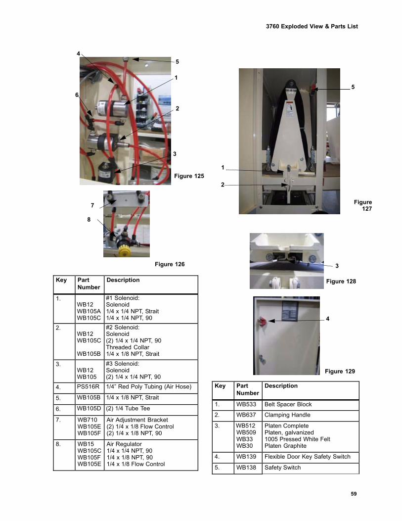
3760 Exploded View & Parts List
Key Part Number
Description
1. WB12 WB105A WB105C
#1 Solenoid: Solenoid 1/4 x 1/4 NPT, Strait 1/4 x 1/4 NPT, 90
2. WB12 WB105C WB105B
#2 Solenoid: Solenoid (2) 1/4 x 1/4 NPT, 90 Threaded Collar 1/4 x 1/8 NPT, Strait
3. WB12 WB105
#3 Solenoid: Solenoid (2) 1/4 x 1/4 NPT, 90
4. PS516R 1/4” Red Poly Tubing (Air Hose)
5. WB105B 1/4 x 1/8 NPT, Strait
6. WB105D (2) 1/4 Tube Tee
7. WB710 WB105E WB105F
Air Adjustment Bracket (2) 1/4 x 1/8 Flow Control (2) 1/4 x 1/8 NPT, 90
8. WB15 WB105C WB105F WB105E
Air Regulator 1/4 x 1/4 NPT, 90 1/4 x 1/8 NPT, 90 1/4 x 1/8 Flow Control
4 5
1
6
2
3
1
Figure 125
2
Figure
127
Figure 126 3
Figure 128
4
Figure 129
Key Part Number
Description
1. WB533 Belt Spacer Block
2. WB637 Clamping Handle
3. WB512 WB509 WB33 WB30
Platen Complete Platen, galvanized 1005 Pressed White Felt Platen Graphite
4. WB139 Flexible Door Key Safety Switch
5. WB138 Safety Switch
5
7
8

60
3760 Exploded View & Parts List
1‐Phase Wiring Schematic

61
3760 Exploded View & Parts List
3‐Phase Wiring Schematic