wide range rotary dtm - tomoevalve.com · wide range rotary control valve pat.no.4245187 r....
TRANSCRIPT

INSTRUCTION MANUAL
DTMWide Range Rotary Control Valve
PAT.NO.4245187
R
C O N T E N T SSTANDARD SPECIFICATIONS
PNEUMATIC DIAPHRAGM-6A/6B SPECIFICATIONS
EXPANDED VIEW OF DTM VALVE
CONSTRUCTION OF PNEUMATIC DIAPHRAGM
PACKAGING
TRANSPORT
STORAGE
UNPACKING
INSTALLATION PRECAUTIONS
INSTALLATION PROCEDURE
HANDLING PRECAUTIONS AFTER INSTALLATION
INSPECTION AND MAINTENANCE
VALVE REMOVAL PROCEDURE
ASSEMBLING AND DISMANTLING OF VALVE
ASSEMBLING AND DISMANTLING OFPNEUMATIC DIAGHRAGM-6A/6B
INSTALLING of ELECTRICAL MOTOR, PNEUMATIC CYLINDER and MANUAL GEAR
LIMITED AVERAGE VELOCITY
ALLOWANCE DIFFERENTIAL PRESSURE
TROUBLESHOOTING
PIPING GASKET
APPLICABLE FLANGE STANDARD
PIPING BOLTS AND NUTS
APPLICABLE PIPE AND MINIMUMINTERNAL DIAMETER OF PIPING
DIMENSIONS AND MASS
2
4
5
6
7
7
7
7
8
11
13
14
15
15
16
17
18
18
21
23
24
25
29
31
�
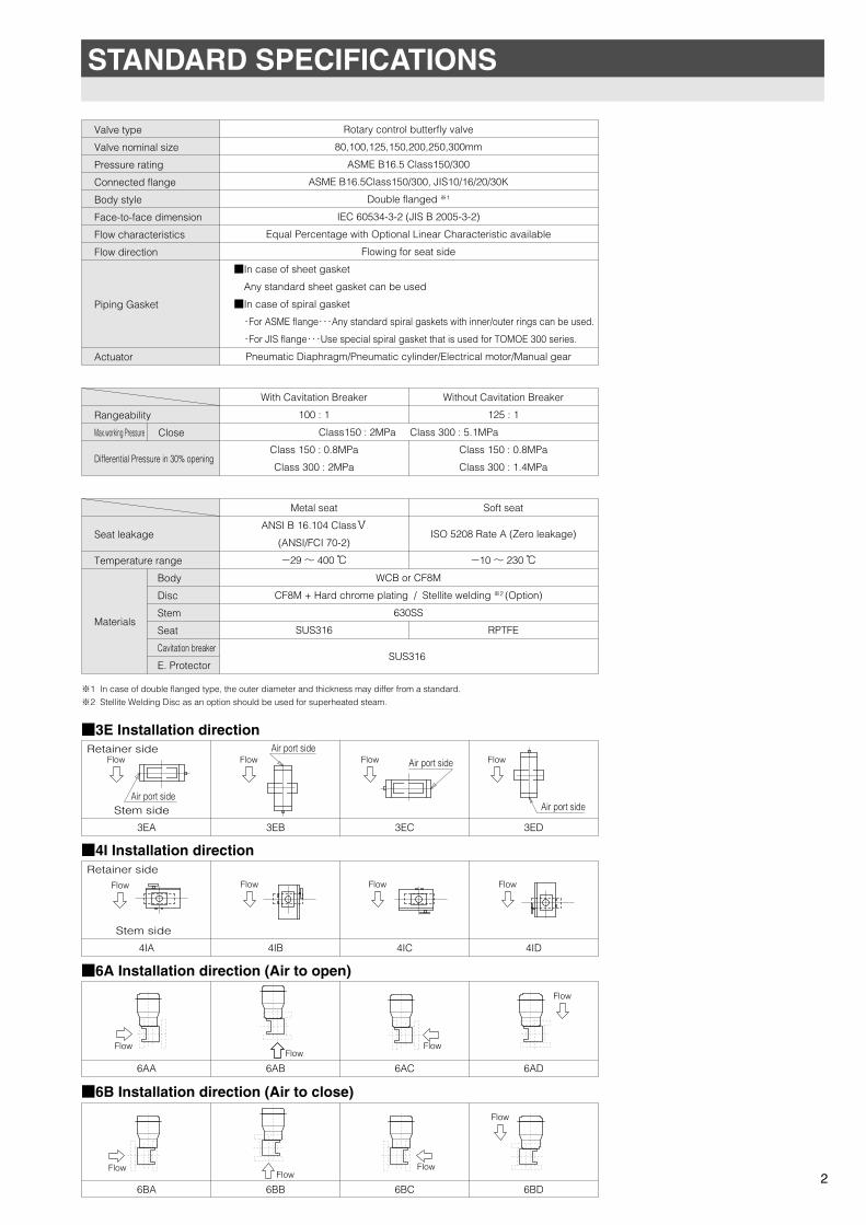
STANDARD SPECIFICATIONS
Valve type
Valve nominal size
Pressure rating
Connected flange
Body style
Face-to-face dimension
Flow characteristics
Flow direction
Piping Gasket
Actuator
Rotary control butterfly valve
80,100,125,150,200,250,300mm
ASME B16.5 Class150/300
ASME B16.5Class150/300, JIS10/16/20/30K
Double flanged ※1
IEC 60534-3-2 (JIS B 2005-3-2)
Equal Percentage with Optional Linear Characteristic available
Flowing for seat side
■In case of sheet gasket
Any standard sheet gasket can be used
■In case of spiral gasket
・For ASME flange・・・Any standard spiral gaskets with inner/outer rings can be used.
・For JIS flange・・・Use special spiral gasket that is used for TOMOE 300 series.
Pneumatic Diaphragm/Pneumatic cylinder/Electrical motor/Manual gear
Close
Rangeability
Max.working Pressure
Differential Pressure in 30% opening
Class150 : 2MPa Class 300 : 5.1MPa
With Cavitation Breaker
100 : 1
Class 150 : 0.8MPa
Class 300 : 2MPa
Without Cavitation Breaker
125 : 1
Class 150 : 0.8MPa
Class 300 : 1.4MPa
Body
Disc
Stem
Seat
Cavitation breaker
E. Protector
Seat leakage
Temperature range
Materials
WCB or CF8M
CF8M + Hard chrome plating / Stellite welding ※2 (Option)
630SS
SUS316
Metal seat
ANSI B 16.104 ClassⅤ
(ANSI/FCI 70-2)
-29 ~ 400 ℃
SUS316
Soft seat
ISO 5208 Rate A (Zero leakage)
-10 ~ 230 ℃
RPTFE
※1 In case of double flanged type, the outer diameter and thickness may differ from a standard.
※2 Stellite Welding Disc as an option should be used for superheated steam.
■3E Installation direction
3EA 3EB 3EC 3ED
■4I Installation direction
4IA 4IB 4IC 4ID
■6A Installation direction (Air to open)
6AA 6AB 6AC 6AD
■6B Installation direction (Air to close)
6BA 6BB 6BC 6BD
Air port sideStem side
Retainer side Air port sideFlow Flow Air port sideFlow
Air port side
Flow
Stem side
Retainer side
Flow Flow Flow Flow
FlowFlow
Flow
Flow
FlowFlow
Flow
Flow
2
TOMOE-eng 11.5.11 10:51 ページ 3
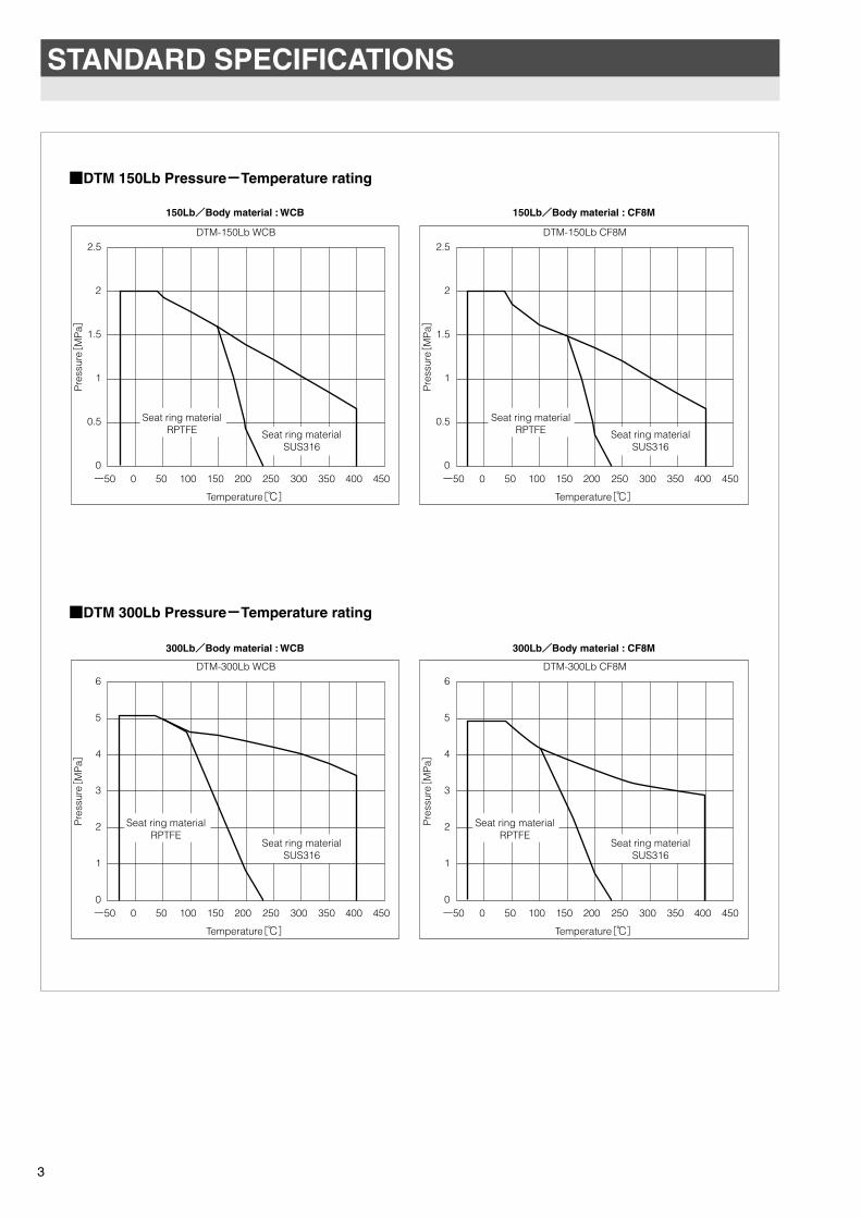
STANDARD SPECIFICATIONS
3
ー50 00
2
1
3
4
5
6
50 100 150
Temperature[℃]
200 250 300 350 400 450
Pre
ssur
e[M
Pa]
DTM-300Lb CF8M
ー50 00
2
1
3
4
5
6
50 100 150
Temperature[℃]
200 250 300 350 400 450
Pre
ssur
e[M
Pa]
DTM-300Lb WCB
ー50 00
0.5
1
1.5
2
2.5
50 100 150
Temperature[℃]
200 250 300 350 400 450
Pre
ssur
e[M
Pa]
DTM-150Lb CF8M
ー50 00
0.5
1
1.5
2
2.5
50 100 150
Temperature[℃]
200 250 300 350 400 450
Pre
ssur
e[M
Pa]
DTM-150Lb WCB
Seat ring materialRPTFE Seat ring material
SUS316
Seat ring materialSUS316
Seat ring materialSUS316
Seat ring materialRPTFE Seat ring material
SUS316
Seat ring materialRPTFE
Seat ring materialRPTFE
■DTM 150Lb Pressure-Temperature rating
■DTM 300Lb Pressure-Temperature rating
150Lb/Body material : WCB
300Lb/Body material : WCB
150Lb/Body material : CF8M
300Lb/Body material : CF8M
TOMOE-eng 10.7.9 5:03 ページ 4

PNEUMATIC DIAPHRAGM-6A/6B SPECIFICATIONS
No.
1
2
3
4
5
6
7
8
9
10
11
12
13
14
15
16
17
18
1. Manual operating unit
2. Positioner except TP8100 ( E/P, P/P )
3. Filter regulator except AW30
Item
Max. Output torque (0.4MPa,Close)
Max. pressure
Air supply pressure
Spring range
Performance ※1
Ambient temperature
Body shell max pressure
Standard valve opening ※2
Port size for air connection
Material
Paint
Operating time ※1
Diaphragm capacity
Diaphragm type
D700
700
0.5
0.4
1.0F.S.
±2.0F.S.
-20~60
1.0
80°(0 to 80°)
Rc1/4
SPHD
FC250
SUS403
CR with nylon
FCD450
Acrylic urethane paint
25
15
D200
200
8
4.7
Unit
N・m
MPa
MPa
MPa
%
%
℃
MPa
°
Sec
Liter
※1 Measurement Condition : ①Supplying air pressure: 0.4MPa
②Accessory : TP8100 positioner and AW30 filter regulator
③No fluid loaded
④Single operating (Open→Close or Close→Open)
※2 Other valve opening than 80° is option.
■Standard
■Option
0.12~0.24
D2200
2200
70
41
0.14~0.24
4
Hysteresis
Linearity
Upper case
Lower case
Stem
Diaphragm
Column
TOMOE-eng 11.2.18 18:28 ページ 5
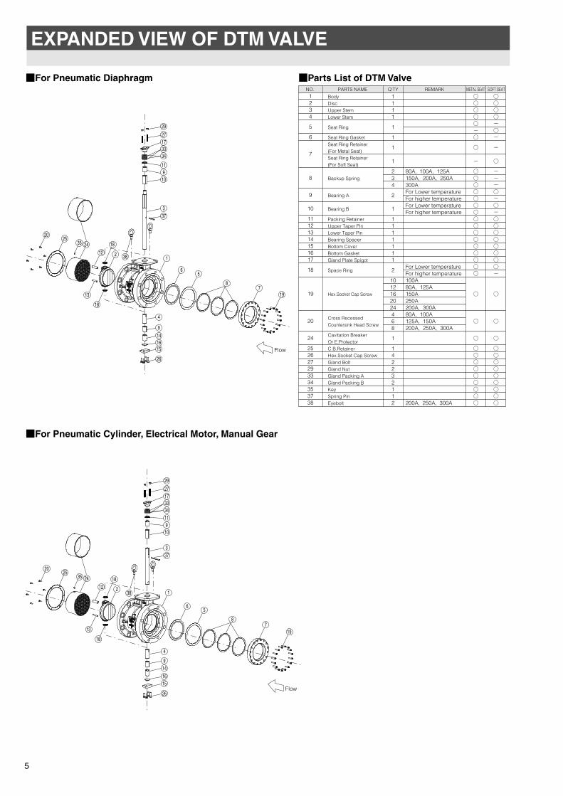
NO. PARTS NAME REMARK METAL SEAT SOFT SEAT
Q'TY
BodyDiscUpper StemLower Stem
Seat Ring
Seat Ring GasketSeat Ring Retainer(For Metal Seat)Seat Ring Retainer(For Soft Seat)
Backup Spring
Bearing A
Bearing B
Packing RetainerUpper Taper PinLower Taper PinBearing SpacerBottom CoverBottom GasketGland Plate Spigot
Space Ring
Hex.Socket Cap Screw
Cross RecessedCountersink Head Screw
Cavitation BreakerOr E.ProtectorC.B.RetainerHex.Socket Cap ScrewGland BoltGland NutGland Packing AGland Packing BKeySpring PinEyebolt
1234
5
6
7
8
9
10
11121314151617
18
19
20
24
252627293334353738
80A, 100A, 125A150A, 200A, 250A300AFor Lower temperatureFor higher temperatureFor Lower temperatureFor higher temperature
For Lower temperatureFor higher temperature100A80A, 125A150A250A200A, 300A80A, 100A125A, 150A200A, 250A, 300A
200A, 250A, 300A
○○○○○-○
○
-
○○○○○�○○○○○○○○○○○
○
○
○
○○○○○○○○○
○○○○-○-
-
○
---○-○-○○○○○○○○-
○
○
○
○○○○○○○○○
1111
1
1
1
1
234
2
1
1111111
2
1012162024468
1
142232112
EXPANDED VIEW OF DTM VALVE
■For Pneumatic Diaphragm ■Parts List of DTM Valve
■For Pneumatic Cylinder, Electrical Motor, Manual Gear
5
19
6
1
5
18
13
4
373
109
11
3334
1727
29
9141615
26
2
24 18
38
3525
20
12
87
6
1
5
18
13
4
373
109
11
3334
1727
29
9141615
26
2
24 18
38
3525
20
12
87
19
Flow
Flow
TOMOE-eng 11.5.9 11:44 ページ 6
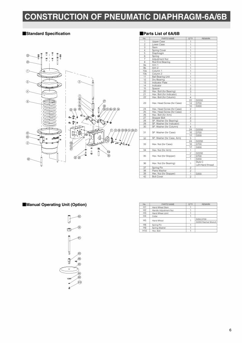
No. PARTS NAME REMARKQ'TYUpper CaseLower CaseStem Spring CoverDiaphragmSpring Adjustment NutRod End BearingArm 1Arm 2Column 1Column 2Ball Bearing UnitDry BearingIndicator PlateIndicator SpacerHex. Bolt (for Bearing)Hex. Bolt (for Indicator)Hex. Bolt (for Column)
Hex. Head Screw (for Case)
Hex. Head Screw (for Case)Hex. Head Screw (for Case)Hex. Bolt (for Arm)Stopper BoltSP. Washer (for Bearing)SP. Washer (for Indicator)SP. Washer (for Column)
SP. Washer (for Case)
SP. Washer (for Case, Arm)
Hex. Nut (for Case)
Hex. Nut (for Arm)
Hex. Nut (for Stopper)
Hex. Nut (for Bearing)
Spring PinPlane WasherHex. Nut (for Stopper)Bolt Cover
12345678
9a9b10a10b1112131415202122
23
24252627282930
31
32
33
34
35
36
37383942
D2200D700D200
D2200D700D200
D2200D700D200
D2200D700D200Style CLeft-Hand thread
D200
11111111111111112314
2214102212314
2416123
2416121221
1
2212
No. PARTS NAME REMARKQ'TY Hand Wheel Stem
Handle Adjustment NutHand Wheel JointCollar
Hand Wheel
Spring PinSpring WasherHex. Bolt
D200,D700D2200:Ratchet Wrench
H1H2H3H4
H5
H8H9
H10
1111
1
111
CONSTRUCTION OF PNEUMATIC DIAPHRAGM-6A/6B
■Parts List of 6A/6B
■Manual Operating Unit (Option)
■Standard Specification
6
10b
3022
9a26
8
7
3
9b 32 34
11 13 14 29 21
1237
10a
35
27
32 25
28 3820
42
2
33
31
6
4
5
1
24
23
36
153539
H2
35
H1
H3
H8
H5
H4
H9
H10
TOMOE-eng 11.2.18 18:28 ページ 7
PACKAGING
TRANSPORT
STORAGE
UNPACKING
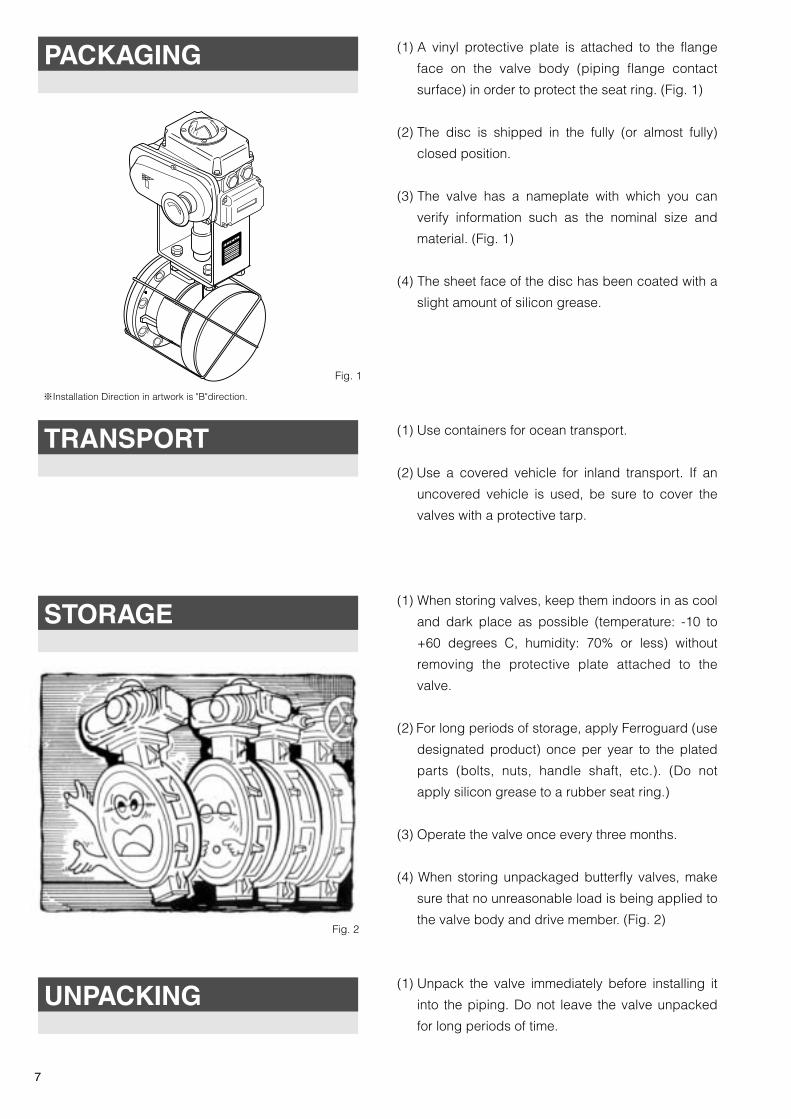
(1) A vinyl protective plate is attached to the flange
face on the valve body (piping flange contact
surface) in order to protect the seat ring. (Fig. 1)
(2) The disc is shipped in the fully (or almost fully)
closed position.
(3) The valve has a nameplate with which you can
verify information such as the nominal size and
material. (Fig. 1)
(4) The sheet face of the disc has been coated with a
slight amount of silicon grease.
(1) Use containers for ocean transport.
(2) Use a covered vehicle for inland transport. If an
uncovered vehicle is used, be sure to cover the
valves with a protective tarp.
(1) When storing valves, keep them indoors in as cool
and dark place as possible (temperature: -10 to
+60 degrees C, humidity: 70% or less) without
removing the protective plate attached to the
valve.
(2) For long periods of storage, apply Ferroguard (use
designated product) once per year to the plated
parts (bolts, nuts, handle shaft, etc.). (Do not
apply silicon grease to a rubber seat ring.)
(3) Operate the valve once every three months.
(4) When storing unpackaged butterfly valves, make
sure that no unreasonable load is being applied to
the valve body and drive member. (Fig. 2)
(1) Unpack the valve immediately before installing it
into the piping. Do not leave the valve unpacked
for long periods of time.
Fig. 1
Fig. 2
7
※Installation Direction in artwork is "B"direction.
TOMOE-eng 11.5.10 2:49 ページ 8
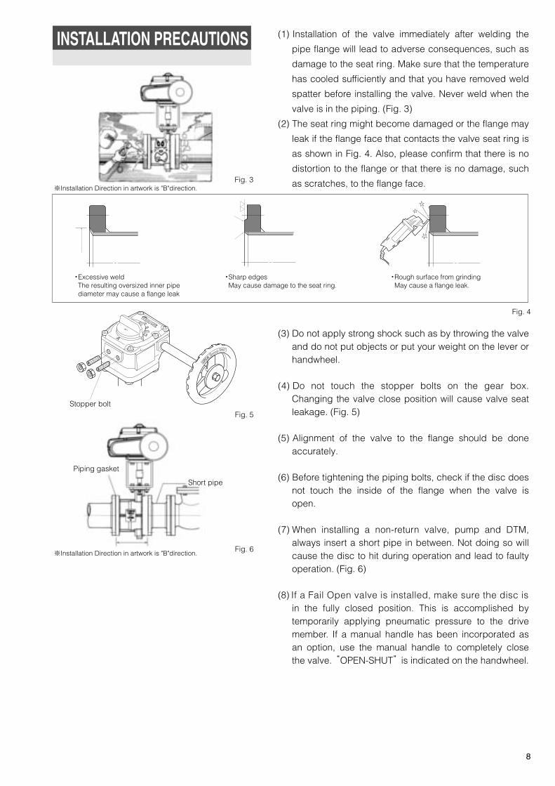
・Excessive weld The resulting oversized inner pipe diameter may cause a flange leak
・Sharp edges May cause damage to the seat ring.
・Rough surface from grindingMay cause a flange leak.
Stopper bolt
Piping gasket
Short pipe
INSTALLATION PRECAUTIONS (1) Installation of the valve immediately after welding the
pipe flange will lead to adverse consequences, such as
damage to the seat ring. Make sure that the temperature
has cooled sufficiently and that you have removed weld
spatter before installing the valve. Never weld when the
valve is in the piping. (Fig. 3)
(2) The seat ring might become damaged or the flange may
leak if the flange face that contacts the valve seat ring is
as shown in Fig. 4. Also, please confirm that there is no
distortion to the flange or that there is no damage, such
as scratches, to the flange face.
(3) Do not apply strong shock such as by throwing the valve and do not put objects or put your weight on the lever or handwheel.
(4) Do not touch the stopper bolts on the gear box. Changing the valve close position will cause valve seat leakage. (Fig. 5)
(5) Alignment of the valve to the flange should be done accurately.
(6) Before tightening the piping bolts, check if the disc does not touch the inside of the flange when the valve is open.
(7) When installing a non-return valve, pump and DTM, always insert a short pipe in between. Not doing so will cause the disc to hit during operation and lead to faulty operation. (Fig. 6)
(8) If a Fail Open valve is installed, make sure the disc isin the fully closed position. This is accomplished by temporarily applying pneumatic pressure to the drive member. If a manual handle has been incorporated as an option, use the manual handle to completely close the valve. “OPEN-SHUT” is indicated on the handwheel.
Fig. 5
Fig. 4
Fig. 3
8
Fig. 6
※Installation Direction in artwork is "B"direction.
※Installation Direction in artwork is "B"direction.
TOMOE-eng 11.5.10 2:50 ページ 9
Piping gasket
PipePipe
PipePipe
Short pipeShort pipe
L2
L1
L
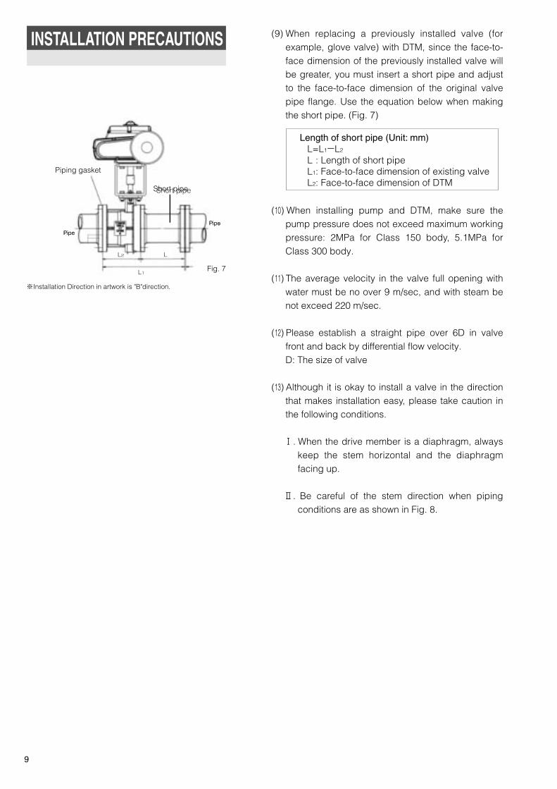
(9) When replacing a previously installed valve (for example, glove valve) with DTM, since the face-to-face dimension of the previously installed valve will be greater, you must insert a short pipe and adjust to the face-to-face dimension of the original valve pipe flange. Use the equation below when making the short pipe. (Fig. 7)
(10) When installing pump and DTM, make sure the pump pressure does not exceed maximum working pressure: 2MPa for Class 150 body, 5.1MPa for Class 300 body.
(11) The average velocity in the valve full opening with water must be no over 9 m/sec, and with steam be not exceed 220 m/sec.
(12) Please establish a straight pipe over 6D in valve front and back by differential flow velocity.D: The size of valve
(13) Although it is okay to install a valve in the direction that makes installation easy, please take caution in the following conditions.� . When the drive member is a diaphragm, always
keep the stem horizontal and the diaphragm facing up.
� . Be careful of the stem direction when piping
conditions are as shown in Fig. 8.
Length of short pipe (Unit: mm)L=L1-L2
L0: Length of short pipeL1: Face-to-face dimension of existing valveL2: Face-to-face dimension of DTM
INSTALLATION PRECAUTIONS
9
Fig. 7
※Installation Direction in artwork is "B"direction.
TOMOE-eng 11.5.10 2:50 ページ 10
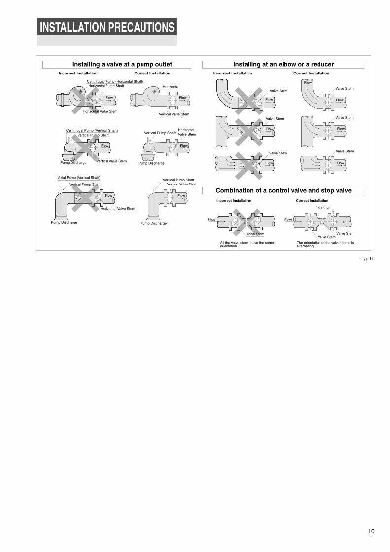
Combination of a control valve and stop valve
Installing a valve at a pump outlet Installing at an elbow or a reducer
Centrifugal Pump (Horizontal Shaft)
Incorrect Installation Correct Installation Incorrect Installation Correct Installation
Incorrect Installation Correct Installation
Horizontal
Vertical Valve Stem
Valve Stem
Valve Stem
Valve Stem Valve Stem
Valve Stem
Valve Stem
Flow Flow
Flow
FlowFlow
FlowFlowFlowFlow
Centrifugal Pump (Vertical Shaft)
Vertical Valve StemPump Discharge
Flow
Horizontal Pump Shaft
Horizontal Valve Stem
Vertical Pump ShaftVertical Pump Shaft
HorizontalValve Stem
Pump Discharge
wolF
Axial Pump (Vertical Shaft)
Horizontal Valve Stem
Pump Discharge
Flow
Vertical Pump ShaftVertical Pump Shaft
Vertical Valve Stem
Pump Discharge
Flow
Valve Stem
3D~5D
Valve Stem
Flow
The orientation of the valve stems isalternating.
Flow
All the valve stems have the sameorientation.
Valve Stem
Pipe
Pipe
Short pipe
Fig. 8
INSTALLATION PRECAUTIONS
10
TOMOE-eng 10.11.29 11:18 ページ 11
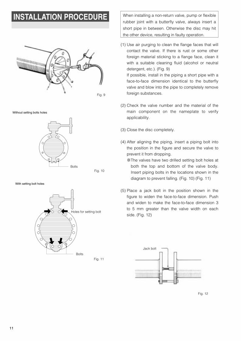
Without setting bolts holes
With setting bolt holes
Fig. 10
Fig. 11
Fig. 12
Holes for setting bolt
Bolts
Bolts
Jack bolt
Fig. 9
When installing a non-return valve, pump or flexible
rubber joint with a butterfly valve, always insert a
short pipe in between. Otherwise the disc may hit
the other device, resulting in faulty operation.
INSTALLATION PROCEDURE
(1) Use air purging to clean the flange faces that will
contact the valve. If there is rust or some other
foreign material sticking to a flange face, clean it
with a suitable cleaning fluid (alcohol or neutral
detergent, etc.). (Fig. 9)
If possible, install in the piping a short pipe with a
face-to-face dimension identical to the butterfly
valve and blow into the pipe to completely remove
foreign substances.
(2) Check the valve number and the material of the
main component on the nameplate to verify
applicability.
(3) Close the disc completely.
(4) After aligning the piping, insert a piping bolt into
the position in the figure and secure the valve to
prevent it from dropping.
※The valves have two drilled setting bolt holes at
both the top and bottom of the valve body.
Insert piping bolts in the locations shown in the
diagram to prevent falling. (Fig. 10) (Fig. 11)
(5) Place a jack bolt in the position shown in the
figure to widen the face-to-face dimension. Push
and widen to make the face-to-face dimension 3
to 5 mm greater than the valve width on each
side. (Fig. 12)
11
TOMOE-eng 10.11.25 23:18 ページ 12
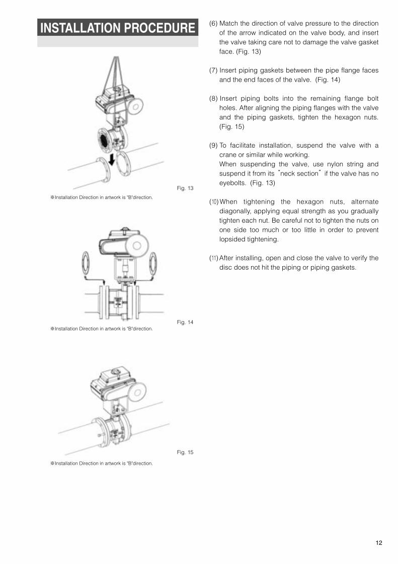
Fig. 13
Fig. 14
Fig. 15
INSTALLATION PROCEDURE (6) Match the direction of valve pressure to the direction of the arrow indicated on the valve body, and insert the valve taking care not to damage the valve gasket face. (Fig. 13)
(7) Insert piping gaskets between the pipe flange faces and the end faces of the valve. (Fig. 14)
(8) Insert piping bolts into the remaining flange bolt holes. After aligning the piping flanges with the valve and the piping gaskets, tighten the hexagon nuts. (Fig. 15)
(9) To facilitate installation, suspend the valve with a crane or similar while working.When suspending the valve, use nylon string and suspend it from its “neck section” if the valve has no eyebolts. (Fig. 13)
(10) When tightening the hexagon nuts, alternate diagonally, applying equal strength as you gradually tighten each nut. Be careful not to tighten the nuts on one side too much or too little in order to prevent lopsided tightening.
(11) After installing, open and close the valve to verify the disc does not hit the piping or piping gaskets.
12
※Installation Direction in artwork is "B"direction.
※Installation Direction in artwork is "B"direction.
※Installation Direction in artwork is "B"direction.
TOMOE-eng 11.5.10 2:50 ページ 13

HANDLING PRECAUTIONS AFTER INSTALLATION
(1) Before beginning operation, air-purge the outside of the
piping and clean the inside of the piping by running water
through the piping.
(2) Prior to operating, increase the internal pressure of the piping
and check for possible leakage from the flange gaskets,
glands, and bottom cover by employing soapy water or
similar.
When doing so, make sure that the internal pressure does
not exceed maximum working pressure: 2MPa for Class 150
body, 5.1MPa for Class 300 body. (Fig. 16)
(3) If leakage is observed from the bottom cover, immediately
retighten the bottom cover installation bolts. Alternate and
tighten gradually with equal strength to avoid lopsided
tightening. If leakage is observed from the flanges or glands,
release the internal pressure and remove the valve from the
piping. Check if there is nothing wrong with the piping
gaskets, and tighten gland-bolts moreover.
(4) Opening and closing operation of the worm gear type must
be done by hand. Do not use a Wilky key on the gear handle.
Doing so can damage the handle and break the valve.
(5) When performing a pressure test, completely open the valve
(if using a pressure higher than the rated pressure). Never
use a fully closed valve in place of a blind flange. If inserting
a blind flange or similar device, take care not to forcibly
insert the flange as the flange face may be damaged on the
DTM, causing leakage.
(6) If the system will not be operated for a prolonged period of
time after the piping work is finished exercise the valve by
opening and closing it once every two weeks.
(7) The life of the valve will become shorter if the valve is
primarily used at an opening less than 20%.
Fig. 16
13
※Installation Direction in artwork is "B"direction.
TOMOE-eng 11.5.10 2:50 ページ 14
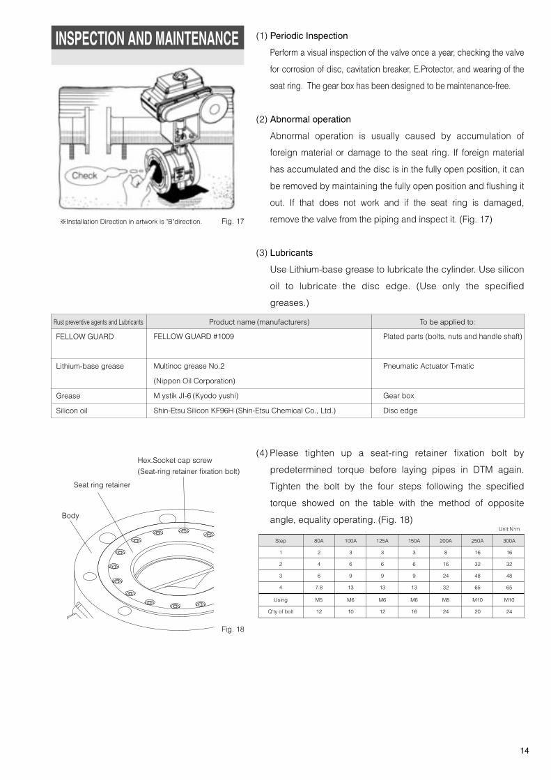
Hex.Socket cap screw
(Seat-ring retainer fixation bolt)
Seat ring retainer
Body
INSPECTION AND MAINTENANCE (1) Periodic Inspection
Perform a visual inspection of the valve once a year, checking the valve
for corrosion of disc, cavitation breaker, E.Protector, and wearing of the
seat ring. The gear box has been designed to be maintenance-free.
(2) Abnormal operation
Abnormal operation is usually caused by accumulation of
foreign material or damage to the seat ring. If foreign material
has accumulated and the disc is in the fully open position, it can
be removed by maintaining the fully open position and flushing it
out. If that does not work and if the seat ring is damaged,
remove the valve from the piping and inspect it. (Fig. 17)
(3) Lubricants
Use Lithium-base grease to lubricate the cylinder. Use silicon
oil to lubricate the disc edge. (Use only the specified
greases.)
(4) Please tighten up a seat-ring retainer fixation bolt by
predetermined torque before laying pipes in DTM again.
Tighten the bolt by the four steps following the specified
torque showed on the table with the method of opposite
angle, equality operating. (Fig. 18)Unit:N・m
Step
1
2
3
4
Using
Q'ty of bolt
80A
2
4
6
7.8
M5
12
100A
3
6
9
13
M6
10
125A
3
6
9
13
M6
12
150A
3
6
9
13
M6
16
200A
8
16
24
32
M8
24
250A
16
32
48
65
M10
20
300A
16
32
48
65
M10
24
Rust preventive agents and Lubricants
FELLOW GUARD
Lithium-base grease
Grease
Silicon oil
FELLOW GUARD #1009
Multinoc grease No.2
(Nippon Oil Corporation)
M ystik JI-6 (Kyodo yushi)
Shin-Etsu Silicon KF96H (Shin-Etsu Chemical Co., Ltd.)
Product name (manufacturers)
Plated parts (bolts, nuts and handle shaft)
Pneumatic Actuator T-matic
Gear box
Disc edge
To be applied to:
Fig. 17
Fig. 18
14
※Installation Direction in artwork is "B"direction.
TOMOE-eng 11.5.10 2:50 ページ 15
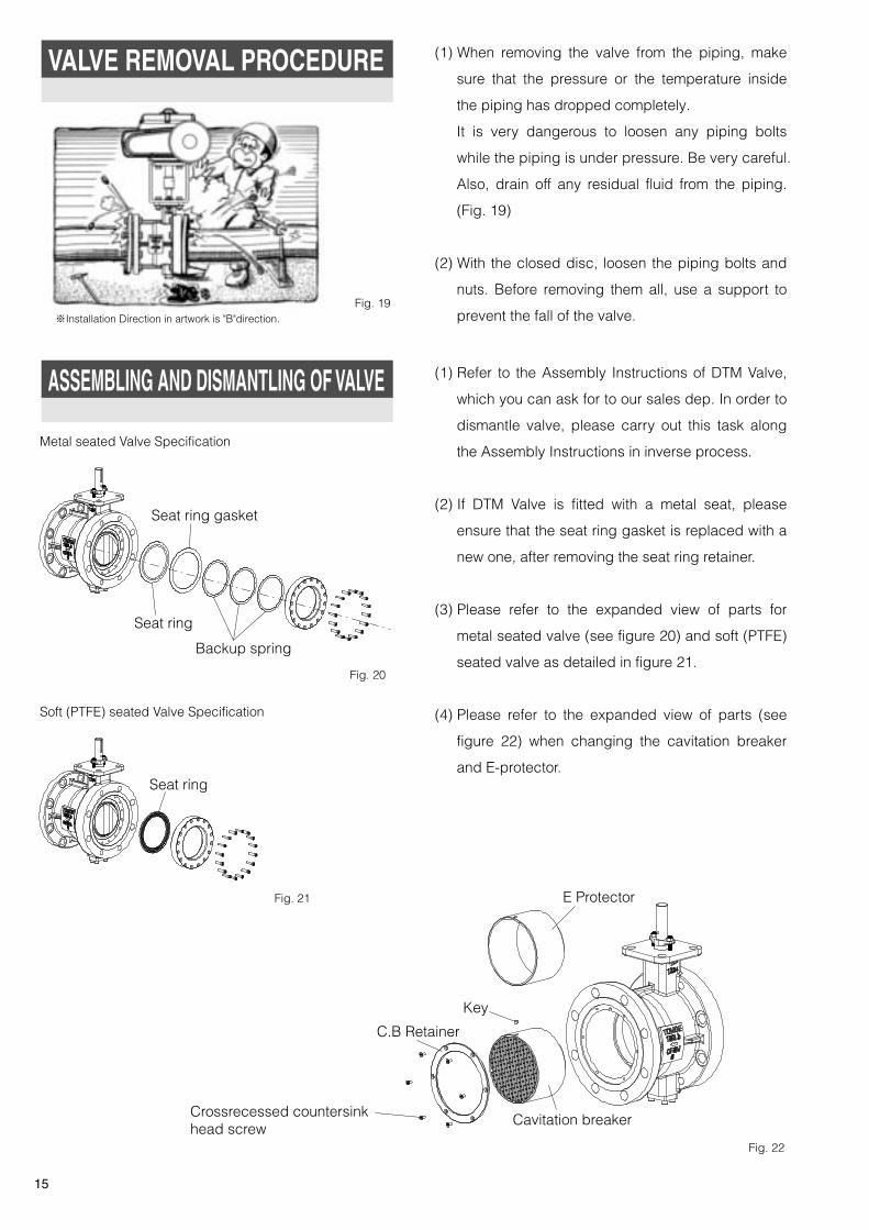
VALVE REMOVAL PROCEDURE (1) When removing the valve from the piping, make
sure that the pressure or the temperature inside
the piping has dropped completely.
It is very dangerous to loosen any piping bolts
while the piping is under pressure. Be very careful.
Also, drain off any residual fluid from the piping.
(Fig. 19)
(2) With the closed disc, loosen the piping bolts and
nuts. Before removing them all, use a support to
prevent the fall of the valve.Fig. 19
Fig. 21
ASSEMBLING AND DISMANTLING OF VALVE (1) Refer to the Assembly Instructions of DTM Valve,
which you can ask for to our sales dep. In order to
dismantle valve, please carry out this task along
the Assembly Instructions in inverse process.
(2) If DTM Valve is fitted with a metal seat, please
ensure that the seat ring gasket is replaced with a
new one, after removing the seat ring retainer.
(3) Please refer to the expanded view of parts for
metal seated valve (see figure 20) and soft (PTFE)
seated valve as detailed in figure 21.
(4) Please refer to the expanded view of parts (see
figure 22) when changing the cavitation breaker
and E-protector.
Metal seated Valve Specification
Soft (PTFE) seated Valve Specification
Fig. 22
Fig. 20
Seat ring gasket
Seat ring
Seat ring
Backup spring
E Protector
Cavitation breaker
Key
C.B Retainer
Crossrecessed countersinkhead screw
※Installation Direction in artwork is "B"direction.
15
TOMOE-eng 11.5.10 2:50 ページ 16

(1) Refer to 「Assembly instruction of 6A/6B」 which
you can ask for to our sales dep, you can do
assembly of pneumatic diaphragm-6A/6B. Please
dismantle the pneumatic diaphragm-6A/6B in
inverse process of the assembling.
(2) Manual operation
Removing the stopper bolt, the manual operating
unit can be installed. The stopper nut must be
fixed surely. After manual operating, the hand
shaft must be returned to the longest state. Please
apply grease to the thread of hand shaft regularly.
(3) Please install pneumatic diaphragm-6A/6B
perpendicularly.
(4) Please do not change the setting of the filter
regulator and positioner. The precision and the
performance of the valve may be compromised as
a result.
(5) Please do not perform a speed adjustment by
using a reducing valve.
(6) Perform an inspection once per year while actuator
is operating and also under suspension.
ASSEMBLING AND DISMANTLINGOF PNEUMATIC DIAGHRAGM-6A/6B
Fig. 23
Fig. 24
Without manual operation
With manual operation
Manual operation unit
Stopper nut
Stopper bolt
Stopper nut
16
TOMOE-eng 11.2.19 4:52 ページ 17
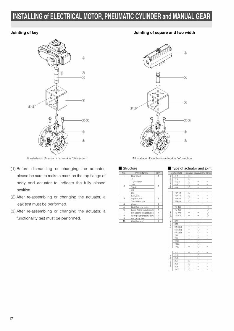
ACTUATOR Key Joint Two Width JointSquare Joint
4I-1 ○ - -4I-2 ○ - -4I-2.5 ○ - -4I-3 ○ - -4I-4 ○ - -
TGA-125 ○ - -TGA-140 ○ - -TGA-160 ○ - -TGA-180 ○ - -
TG-10S - - ○TG-12S - - ○TG-14S - - ○TG-20S - - ○
K30 - - -K70 - ○ -K170(S) - ○ -K370(S) - ○ -K700(S) - ○ -T35 - - -T85 - ○ -T200 - ○ -T380 - ○ -T750 - ○ -
2U1 - ○ -2U2 - ○ -2U3 - ○ -2U4 ○ - -2U5 ○ - -2U6 ○ - -2K03 ○ - -
Elec
trica
l Mot
orP
neum
atic
Cyl
ind
erM
anua
l Gea
r
INSTALLING of ELECTRICAL MOTOR, PNEUMATIC CYLINDER and MANUAL GEAR
Jointing of key Jointing of square and two width
NO. PARTS NAME Q'TY
Bear-Shaft4IT-DYNAMOTGATG-S2U2KKey JointSquare JointTwo Width JointColumnBolt (Actuator side)Spring Washer (Actuator side)Bolt (Used for fixing body side)Spring Washer (Body side)Nut (Body side)Key (Actuator)
1
2
3
456789
10
1
1
1
1444441
■ Structure ■ Type of actuator and joint(1) Before dismantling or changing the actuator,
please be sure to make a mark on the top flange of
body and actuator to indicate the fully closed
position.
(2) After re-assembling or changing the actuator, a
leak test must be performed.
(3) After re-assembling or changing the actuator, a
functionality test must be performed.
17
2
10
3
4
9
1
7 8-
2
3
4
9
1
7 8-
65 -5 6-
※Installation Direction in artwork is "B"direction. ※Installation Direction in artwork is "A"direction.
TOMOE-eng 11.5.10 2:50 ページ 18
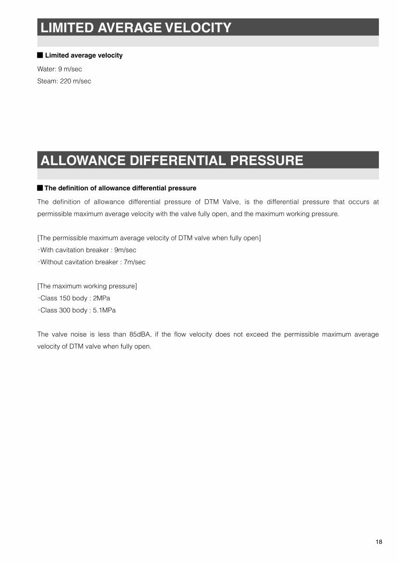
LIMITED AVERAGE VELOCITY
■ Limited average velocity
Water: 9 m/sec
Steam: 220 m/sec
ALLOWANCE DIFFERENTIAL PRESSURE
■ The definition of allowance differential pressure
The definition of allowance differential pressure of DTM Valve, is the differential pressure that occurs at
permissible maximum average velocity with the valve fully open, and the maximum working pressure.
[The permissible maximum average velocity of DTM valve when fully open]
・With cavitation breaker : 9m/sec
・Without cavitation breaker : 7m/sec
[The maximum working pressure]
・Class 150 body : 2MPa
・Class 300 body : 5.1MPa
The valve noise is less than 85dBA, if the flow velocity does not exceed the permissible maximum average
velocity of DTM valve when fully open.
18
TOMOE-eng 11.2.21 10:27 ページ 19
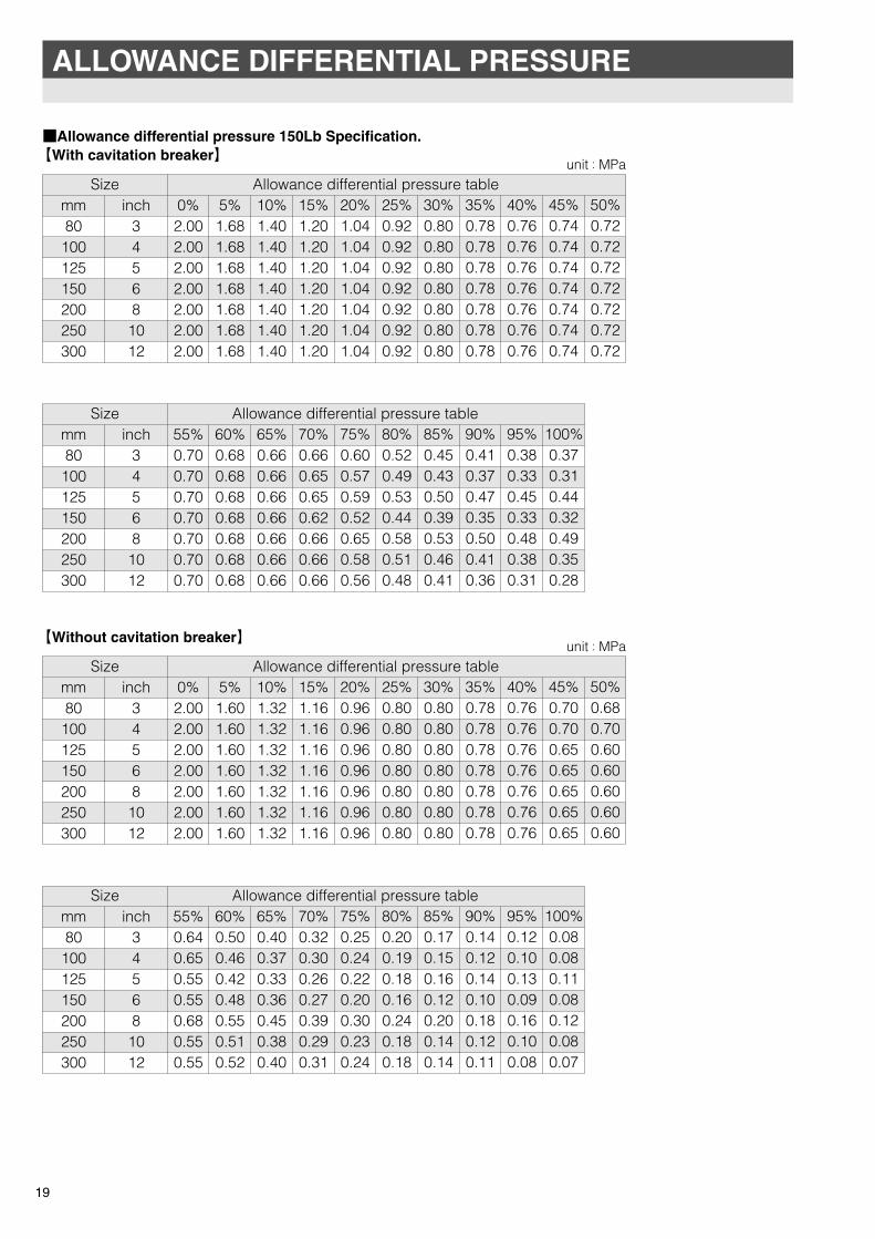
■Allowance differential pressure 150Lb Specification. 【With cavitation breaker】
【Without cavitation breaker】
19
ALLOWANCE DIFFERENTIAL PRESSURE
unit:MPa
mm80100125150200250300
inch34568
1012
Size Allowance differential pressure table0%2.002.002.002.002.002.002.00
5%1.681.681.681.681.681.681.68
10%1.401.401.401.401.401.401.40
15%1.201.201.201.201.201.201.20
20%1.041.041.041.041.041.041.04
25%0.920.920.920.920.920.920.92
30%0.800.800.800.800.800.800.80
35%0.780.780.780.780.780.780.78
40%0.760.760.760.760.760.760.76
45%0.740.740.740.740.740.740.74
50%0.720.720.720.720.720.720.72
mm80100125150200250300
inch34568
1012
Size Allowance differential pressure table55%0.700.700.700.700.700.700.70
60%0.680.680.680.680.680.680.68
65%0.660.660.660.660.660.660.66
70%0.660.650.650.620.660.660.66
75%0.600.570.590.520.650.580.56
80%0.520.490.530.440.580.510.48
85%0.450.430.500.390.530.460.41
90%0.410.370.470.350.500.410.36
95%0.380.330.450.330.480.380.31
100%0.370.310.440.320.490.350.28
unit:MPa
mm80100125150200250300
inch34568
1012
Size Allowance differential pressure table0%2.002.002.002.002.002.002.00
5%1.601.601.601.601.601.601.60
10%1.321.321.321.321.321.321.32
15%1.161.161.161.161.161.161.16
20%0.960.960.960.960.960.960.96
25%0.800.800.800.800.800.800.80
30%0.800.800.800.800.800.800.80
35%0.780.780.780.780.780.780.78
40%0.760.760.760.760.760.760.76
45%0.700.700.650.650.650.650.65
50%0.680.700.600.600.600.600.60
mm80100125150200250300
inch34568
1012
Size Allowance differential pressure table55%0.640.650.550.550.680.550.55
60%0.500.460.420.480.550.510.52
65%0.400.370.330.360.450.380.40
70%0.320.300.260.270.390.290.31
75%0.250.240.220.200.300.230.24
80%0.200.190.180.160.240.180.18
85%0.170.150.160.120.200.140.14
90%0.140.120.140.100.180.120.11
95%0.120.100.130.090.160.100.08
100%0.080.080.110.080.120.080.07
TOMOE-eng 10.7.9 5:05 ページ 20

ALLOWANCE DIFFERENTIAL PRESSURE
■Allowance differential pressure 300Lb Specification. 【With cavitation breaker】
【Without cavitation breaker】
20
unit:MPa
mm80100125150200250300
inch345681012
Size Allowance differential pressure table0%5.105.105.105.105.105.105.10
5%4.204.204.204.204.204.204.20
10%3.503.503.503.503.503.503.50
15%3.003.003.003.003.003.003.00
20%2.602.602.602.602.602.602.60
25%2.302.302.302.302.302.302.30
30%2.002.002.002.002.002.002.00
35%1.801.801.801.801.801.801.80
40%1.621.621.621.621.621.621.62
45%1.451.451.451.451.451.451.45
50%1.301.301.301.301.301.301.30
mm80100125150200250300
inch345681012
Size Allowance differential pressure table55%1.151.151.151.151.201.201.20
60%1.151.111.061.151.151.151.15
65%0.960.910.860.891.110.970.97
70%0.790.750.730.700.890.770.78
75%0.660.630.630.560.730.640.62
80%0.560.530.560.460.630.540.51
85%0.480.450.520.400.560.470.43
90%0.420.380.480.360.520.420.36
95%0.390.340.460.340.490.390.31
100%0.370.310.440.320.490.350.28
unit:MPa
mm80100125150200250300
inch345681012
Size Allowane differential pressure table0%5.105.105.105.105.105.105.10
5%3.803.803.803.803.803.803.80
10%3.303.303.303.303.303.303.30
15%2.802.802.802.802.802.802.80
20%2.302.302.302.302.302.302.30
25%1.801.801.801.801.801.801.80
30%1.401.401.401.401.401.401.40
35%1.301.301.251.301.301.301.30
40%1.001.000.951.001.001.001.00
45%0.700.700.650.650.750.700.70
50%0.700.700.600.600.700.650.65
mm80100125150200250300
inch345681012
Size Allowance differential pressure table55%0.650.650.550.550.700.630.63
60%0.580.540.480.560.650.590.61
65%0.440.410.360.400.580.420.45
70%0.340.320.280.290.420.310.34
75%0.270.260.230.210.320.240.25
80%0.210.200.190.160.250.180.19
85%0.170.160.170.130.210.150.15
90%0.140.120.150.110.180.120.11
95%0.120.100.130.090.170.100.08
100%0.080.080.110.080.120.080.07
TOMOE-eng 10.7.9 5:05 ページ 21

Please refer to the following when there is a problem with a valve.
There is leakage from the gasket between
the valve body and pipe flange faces.
There is a leak from the gland.
There is a leak from the bottom cover.
The piping bolts are loose or they
were not tightened evenly.
The valve is misaligned.
The wrong piping gasket was selected.
The gland bolts are loose.
The gland packing is worn away, or deterioration.
The bottom cover bolts are loose.
Retighten piping bolts.
Loosen the bolts and realign the valve correctly.
Refer to 「DTM piping gasket」.
Re-tighten the gland nut.
Replace the gland packing.
Re-tighten the bottom cover bolts.
Problem Cause Countermeasure
TROUBLESHOOTING
※Installation Direction in artwork is "B"direction.
※Installation Direction in artwork is "B"direction.
※Installation Direction in artwork is "B"direction.
21
TOMOE-eng 11.5.10 2:50 ページ 22
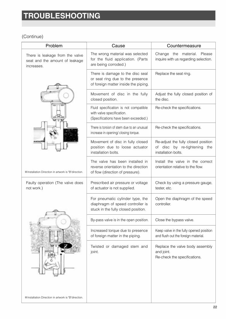
There is leakage from the valve seat and the amount of leakage increases.
Faulty operation (The valve does not work.)
The wrong material was selected for the fluid application. (Parts are being corroded.)
There is damage to the disc seal or seat ring due to the presence of foreign matter inside the piping.
Movement of disc in the fully closed position.
Fluid specification is not compatible with valve specification.(Specifications have been exceeded.)
There is torsion of stem due to an unusual increase in opening/ closing torque.
Movement of disc in fully closed position due to loose actuator installation bolts.
The valve has been installed in reverse orientation to the direction of flow (direction of pressure).
Prescribed air pressure or voltage of actuator is not supplied.
For pneumatic cylinder type, the diaphragm of speed controller is stuck in the fully closed position.
By-pass valve is in the open position.
Increased torque due to presence of foreign matter in the piping.
Twisted or damaged stem and joint.
Change the material. Please inquire with us regarding selection.
Replace the seat ring.
Adjust the fully closed position of the disc.
Re-check the specifications.
Re-check the specifications.
Re-adjust the fully closed position of disc by re-tightening the installation bolts.
Install the valve in the correct orientation relative to the flow.
Check by using a pressure gauge, tester, etc.
Open the diaphragm of the speed controller.
Close the bypass valve.
Keep valve in the fully opened position and flush out the foreign material.
Replace the valve body assembly and joint.Re-check the specifications.
Problem Cause Countermeasure
22
(Continue)
TROUBLESHOOTING
※Installation Direction in artwork is "B"direction.
※Installation Direction in artwork is "B"direction.
TOMOE-eng 11.5.10 2:50 ページ 23
φD1
φD2
φD3
φD4
4.5
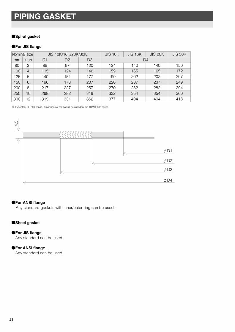
■Spiral gasket
●For JIS flange
●For ANSI flange Any standard gaskets with inner/outer ring can be used. ■Sheet gasket ●For JIS flange Any standard can be used. ●For ANSI flange Any standard can be used.
※ Except for JIS 30K flange, dimensions of the gasket designed for the TOMOE300 series
23
PIPING GASKET
mm80100125150200250300
inch34568
1012
Nominal size JIS 10K/16K/20K/30KD4D1
89115140166217268319
D297124151178227282331
D3120146177207257318362
JIS 10K
134159190220270332377
JIS 16K
140165202237282354404
JIS 20K
140165202237282354404
JIS 30K
150172207249294360418
TOMOE-eng 10.7.9 5:05 ページ 24
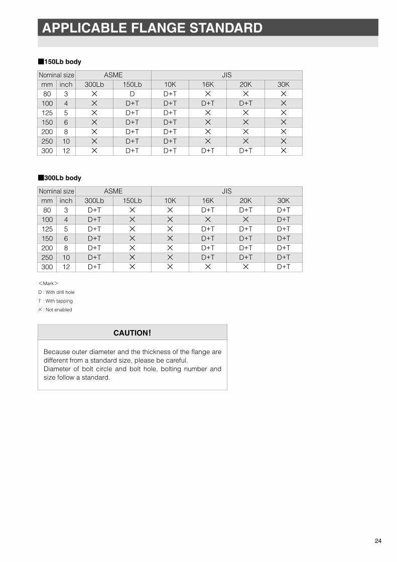
APPLICABLE FLANGE STANDARD
CAUTION!
Because outer diameter and the thickness of the flange are different from a standard size, please be careful.Diameter of bolt circle and bolt hole, bolting number and size follow a standard.
<Mark>
D : With drill hole
T : With tapping
× : Not enabled
24
■300Lb body
mm80
100125150200250300
inch345681012
Nominal size ASME JIS300LbD+TD+TD+TD+TD+TD+TD+T
150Lb×××××××
10K×××××××
16KD+T×
D+TD+TD+TD+T×
20KD+T×
D+TD+TD+TD+T×
30KD+TD+TD+TD+TD+TD+TD+T
■150Lb body
mm80
100125150200250300
inch345681012
Nominal size ASME JIS300Lb×××××××
150LbD
D+TD+TD+TD+TD+TD+T
10KD+TD+TD+TD+TD+TD+TD+T
16K×
D+T××××
D+T
20K×
D+T××××
D+T
30K×××××××
TOMOE-eng 10.11.25 23:20 ページ 25
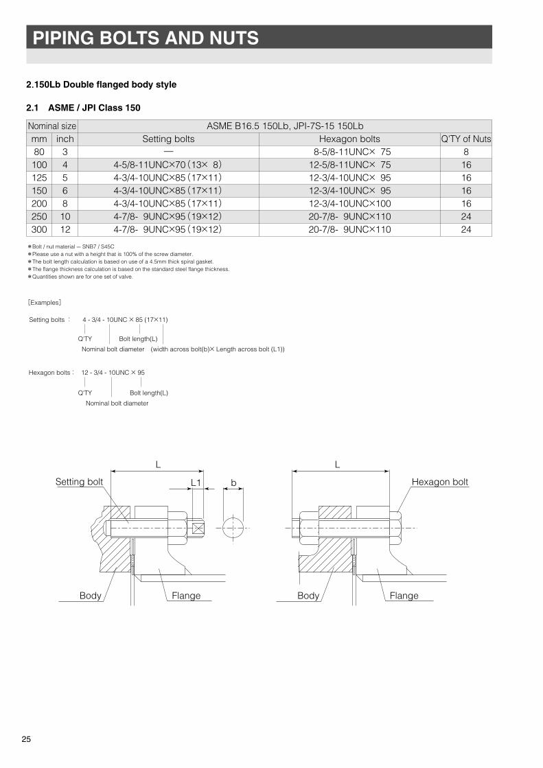
2.150Lb Double flanged body style
2.1 ASME / JPI Class 150
Setting bolts : 4 - 3/4 - 10UNC × 85 (17×11)
Q'TY
Q'TY
[Examples]
Hexagon bolts : 12 - 3/4 - 10UNC × 95
Nominal bolt diameter
Bolt length(L)
(width across bolt(b)× Length across bolt (L1))
Nominal bolt diameter
Bolt length(L)
25
PIPING BOLTS AND NUTS
*Bolt / nut material --- SNB7 / S45C*Please use a nut with a height that is 100% of the screw diameter.*The bolt length calculation is based on use of a 4.5mm thick spiral gasket.*The flange thickness calculation is based on the standard steel flange thickness.*Quantities shown are for one set of valve.
mm80
100125150200250300
inch34568
1012
Nominal size ASME B16.5 150Lb, JPI-7S-15 150LbSetting bolts Hexagon bolts Q'TY of Nuts
―4-5/8-11UNC×70(13× 8)4-3/4-10UNC×85(17×11)4-3/4-10UNC×85(17×11)4-3/4-10UNC×85(17×11)4-7/8- 9UNC×95(19×12)4-7/8- 9UNC×95(19×12)
8-5/8-11UNC× 7512-5/8-11UNC× 7512-3/4-10UNC× 9512-3/4-10UNC× 9512-3/4-10UNC×10020-7/8- 9UNC×11020-7/8- 9UNC×110
8161616162424
L L
Hexagon boltL1 b
Body Body
Setting bolt
Flange Flange
TOMOE-eng 10.11.25 23:20 ページ 26
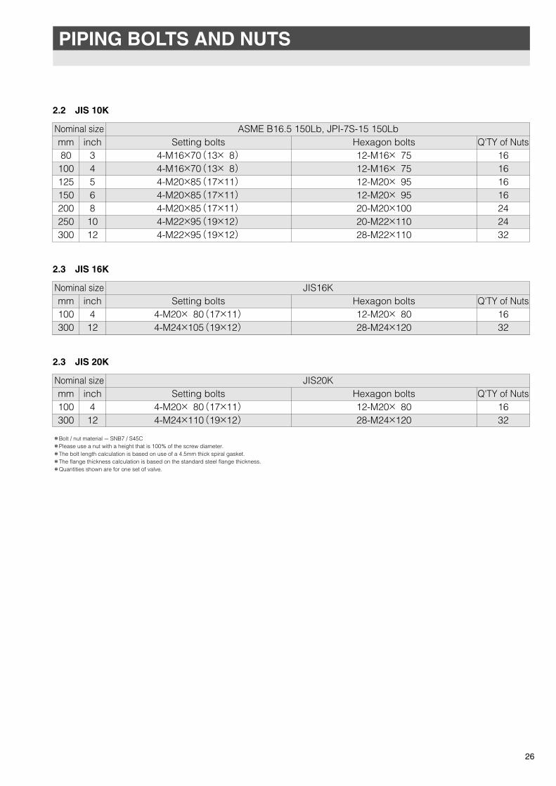
PIPING BOLTS AND NUTS
2.2 JIS 10K
2.3 JIS 16K
2.3 JIS 20K
26
mm80
100125150200250300
inch345681012
Nominal size ASME B16.5 150Lb, JPI-7S-15 150LbSetting bolts Hexagon bolts Q'TY of Nuts
4-M16×70(13× 8)4-M16×70(13× 8)4-M20×85(17×11)4-M20×85(17×11)4-M20×85(17×11)4-M22×95(19×12)4-M22×95(19×12)
12-M16× 7512-M16× 7512-M20× 9512-M20× 9520-M20×10020-M22×11028-M22×110
16161616242432
mm100300
inch412
Nominal size JIS16KSetting bolts Hexagon bolts Q'TY of Nuts
4-M20× 80(17×11)4-M24×105(19×12)
12-M20× 8028-M24×120
1632
mm100300
inch412
Nominal size JIS20KSetting bolts Hexagon bolts Q'TY of Nuts
4-M20× 80(17×11)4-M24×110(19×12)
12-M20× 8028-M24×120
1632
*Bolt / nut material --- SNB7 / S45C*Please use a nut with a height that is 100% of the screw diameter.*The bolt length calculation is based on use of a 4.5mm thick spiral gasket.*The flange thickness calculation is based on the standard steel flange thickness.*Quantities shown are for one set of valve.
TOMOE-eng 10.11.25 23:20 ページ 27
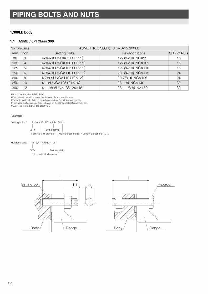
1.300Lb body
1.1 ASME / JPI Class 300
Setting bolts : 4 - 3/4 - 10UNC × 85 (17×11)
Q'TY
Q'TY
[Examples]
Hexagon bolts : 12 - 3/4 - 10UNC × 95
Nominal bolt diameter
Bolt length(L)
(width across bolt(b)× Length across bolt (L1))
Nominal bolt diameter
Bolt length(L)
27
PIPING BOLTS AND NUTS
mm80
100125150200250300
inch34568
1012
Nominal size ASME B16.5 300Lb, JPI-7S-15 300LbSetting bolts Hexagon bolts Q'TY of Nuts
4-3/4-10UNC×85(17×11)4-3/4-10UNC×100(17×11)4-3/4-10UNC×105(17×11)4-3/4-10UNC×110(17×11)4-7/8-9UNC×110(19×12)4-1-8UNC×125(21×14)4-1 1/8-8UN×135(24×16)�
12-3/4-10UNC×9512-3/4-10UNC×10512-3/4-10UNC×11020-3/4-10UNC×11520-7/8-9UNC×12528-1-8UNC×14028-1 1/8-8UN×150
16161624243232
*Bolt / nut material --- SNB7 / S45C*Please use a nut with a height that is 100% of the screw diameter.*The bolt length calculation is based on use of a 4.5mm thick spiral gasket.*The flange thickness calculation is based on the standard steel flange thickness.*Quantities shown are for one set of valve.
L L
HexagonL1 b
FlangeBody FlangeBody
Setting bolt
TOMOE-eng 10.11.25 23:20 ページ 28
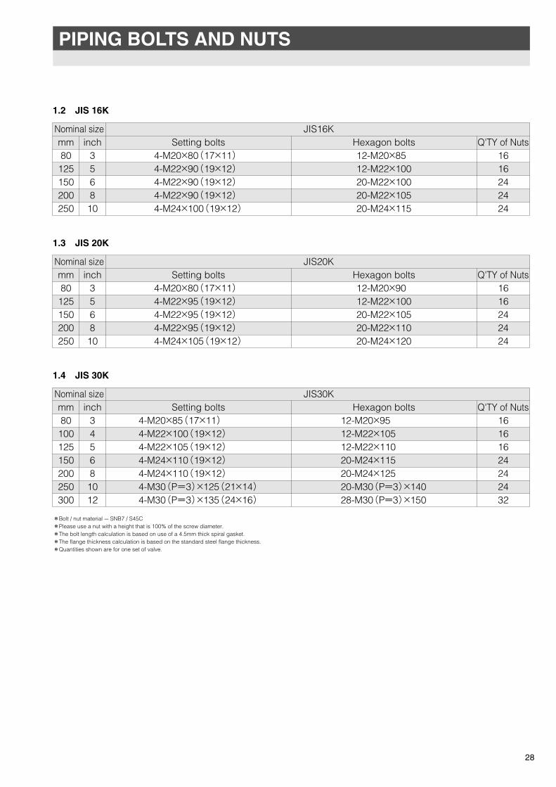
PIPING BOLTS AND NUTS
28
1.4 JIS 30K
mm80
100125150200250300
inch345681012
Nominal size JIS30KSetting bolts Hexagon bolts Q'TY of Nuts
4-M20×85(17×11)4-M22×100(19×12)4-M22×105(19×12)4-M24×110(19×12)4-M24×110(19×12)4-M30(P=3)×125(21×14)4-M30(P=3)×135(24×16)�
12-M20×9512-M22×10512-M22×11020-M24×11520-M24×12520-M30(P=3)×14028-M30(P=3)×150
16161624242432
1.3 JIS 20K
mm80
125150200250
inch356810
Nominal size JIS20KSetting bolts Hexagon bolts Q'TY of Nuts
4-M20×80(17×11)4-M22×95(19×12)4-M22×95(19×12)4-M22×95(19×12)4-M24×105(19×12)�
12-M20×9012-M22×10020-M22×10520-M22×11020-M24×120
1616242424
1.2 JIS 16K
�
mm80
125150200250
inch356810
Nominal size JIS16KSetting bolts Hexagon bolts Q'TY of Nuts
4-M20×80(17×11)4-M22×90(19×12)4-M22×90(19×12)4-M22×90(19×12)4-M24×100(19×12)�
12-M20×8512-M22×10020-M22×10020-M22×10520-M24×115
1616242424
*Bolt / nut material --- SNB7 / S45C*Please use a nut with a height that is 100% of the screw diameter.*The bolt length calculation is based on use of a 4.5mm thick spiral gasket.*The flange thickness calculation is based on the standard steel flange thickness.*Quantities shown are for one set of valve.
TOMOE-eng 10.11.25 23:20 ページ 29
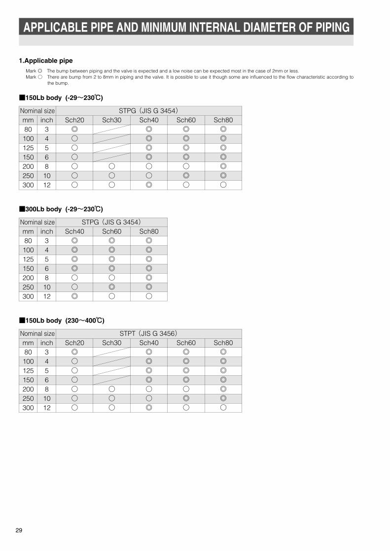
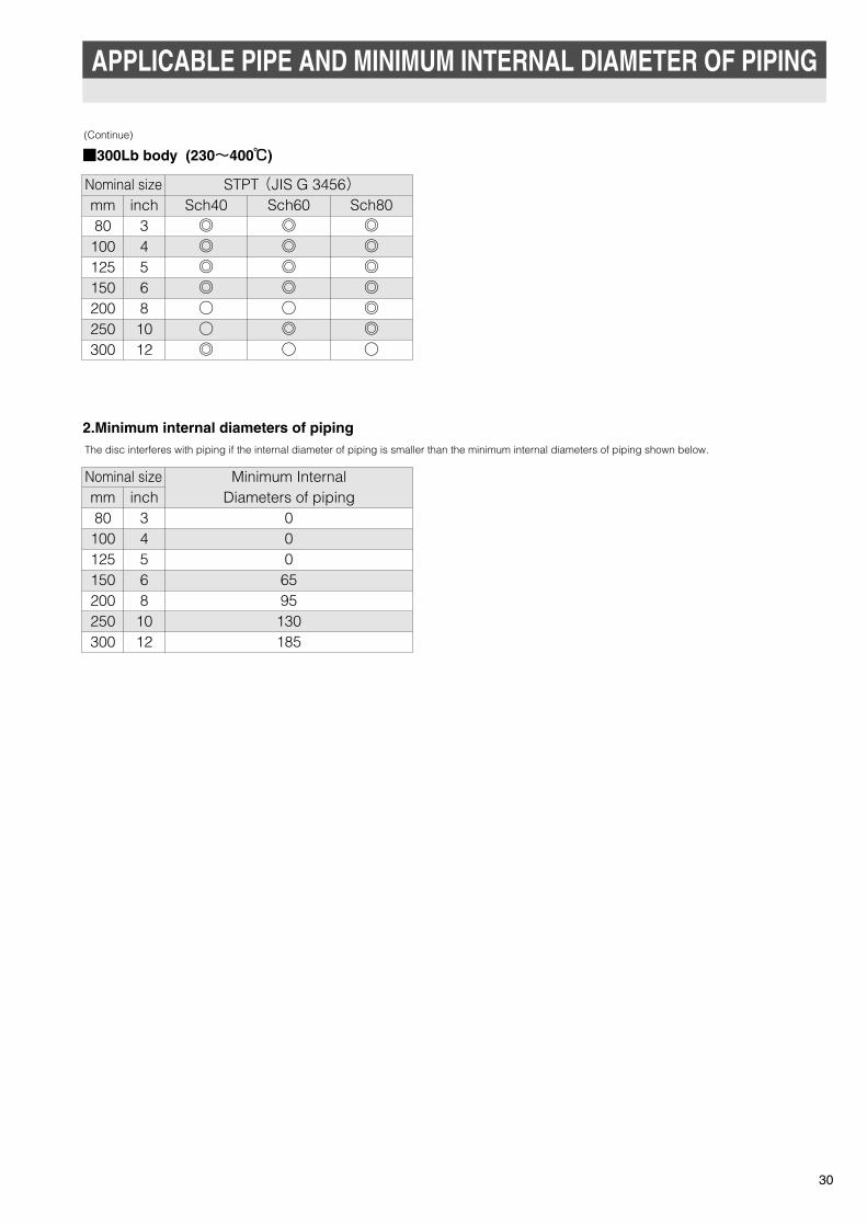
1.Applicable pipe
■150Lb body (-29~230℃)
■300Lb body (-29~230℃)
■150Lb body (230~400℃)
29
APPLICABLE PIPE AND MINIMUM INTERNAL DIAMETER OF PIPING
mm80
100125150200250300
inch34568
1012
Sch20◎�○�○�○�○�○�○�
Sch30
○�○�○�
Sch40◎�◎�◎�◎�○�○�◎�
Sch60◎�◎�◎�◎�○�◎�○�
Sch80◎�◎�◎�◎�◎�◎�○�
Nominal size STPG (JIS G 3454)�
mm80100125150200250300
inch34568
1012
Sch40◎�◎�◎�◎�○�○�◎�
Sch60◎�◎�◎�◎�○�◎�○�
Sch80◎�◎�◎�◎�◎�◎�○�
Nominal size STPG (JIS G 3454)�
mm80100125150200250300
inch34568
1012
Sch20◎�○�○�○�○�○�○�
Sch30
○�○�○�
Sch40◎�◎�◎�◎�○�○�◎�
Sch60◎�◎�◎�◎�○�◎�○�
Sch80◎�◎�◎�◎�◎�◎�○�
Nominal size STPT (JIS G 3456)�
Mark ◎ The bump between piping and the valve is expected and a low noise can be expected most in the case of 2mm or less.Mark ○ There are bump from 2 to 8mm in piping and the valve. It is possible to use it though some are influenced to the flow characteristic according to
the bump.
TOMOE-eng 10.11.25 22:56 ページ 30
APPLICABLE PIPE AND MINIMUM INTERNAL DIAMETER OF PIPING
■300Lb body (230~400℃)
2.Minimum internal diameters of pipingThe disc interferes with piping if the internal diameter of piping is smaller than the minimum internal diameters of piping shown below.
(Continue)
30
mm80
100125150200250300
inch345681012
Sch40◎ ◎ ◎ ◎ ○ ○ ◎
Sch60◎ ◎ ◎ ◎ ○ ◎ ○
Sch80◎ ◎ ◎ ◎ ◎ ◎ ○
Nominal size STPT (JIS G 3456)
mm80100125150200250300
inch345681012
0006595130185
Nominal size Minimum InternalDiameters of piping
TOMOE-eng 10.11.29 10:56 ページ 31
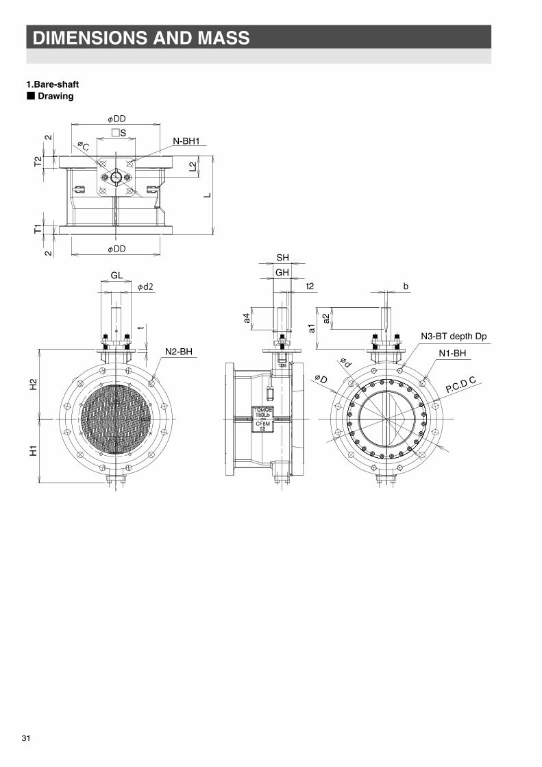
1.Bare-shaft■ Drawing
31
DIMENSIONS AND MASS
CF8M
T1
L
L2
b
H1
t
H2
a1
a2N3-BT depth Dp
N1-BH
D
N2-BH
P.C.D C
□S
1N-BH1
T2
2
t2
2
GL GH
a4SH
φ�
φ�
φ�
φ�
φ�
φ�
TOMOE-eng 10.10.12 17:58 ページ 32
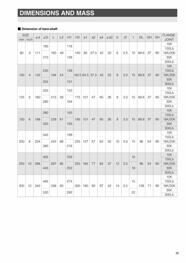
DIMENSIONS AND MASS
■ Dimension of bare-shaft
32
mm
80
100
125
150
200
250
300
inch
3
4
5
6
8
10
12
φd
111
132
160
188
234
286
342
φD
190
210
230
255
255
280
280
320
345
380
405
445
485
520
L
165
194
213
229
243
297
338
L2
49
54
58
61
68
85
93
H1
118
128
139
151
152
164
163
183
199
216
233
252
274
292
H2
140
162.5
175
195
225
255
300
a1
85
84.5
101
101
127
165
180
a2
37.3
37.3
47
47
57
77
92
a4
43
43
60
60
62
82
97
φd2
20
22
26
26
32
37
42
b
6
8
8
8
10
12
14
t2
2.5
3.0
3.0
3.0
3.0
3.0
3.5
t
15
15
15
15
15
15
18
15
22
GL
68.6
68.6
68.6
68.6
96
96
128
GH
37
37
37
37
54
54
71
SH
80
80
80
80
80
80
80
FLANGE JOINT10K
150Lb16K/20K
30K300Lb10K
150Lb16K/20K
30K300Lb10K
150Lb16K/20K
30K300Lb10K
150Lb16K/20K
30K300Lb10K
150Lb16K/20K
30K300Lb10K
150Lb16K/20K
30K300Lb10K
150Lb16K/20K
30K300Lb
SIZE
TOMOE-eng 10.11.25 22:56 ページ 33

(Continue)
33
DIMENSIONS AND MASS
mm
80
100
125
150
200
250
300
inch
3
4
5
6
8
10
12
T2
32
35
27
38
40
42
43
45
45
47
47
52
51
55
T1
25
29
25
32
25
35
26
37
31
43
33
48
35
51
DD
127.0
157.2
185.7
215.9
269.9
323.8
381.0
FLANGEJOINT10K
150Lb16K/20K
30K300Lb10K
150Lb16K/20K
30K300Lb10K
150Lb16K/20K
30K300Lb10K
150Lb16K/20K
30K300Lb10K
150Lb16K/20K
30K300Lb10K
150Lb16K/20K
30K300Lb10K
150Lb16K/20K
30K300Lb
P.C.DC
150152.4160170
168.3175
190.5185195200210
215.9225230235240
241.3260275
269.9290
298.5305320
330.2355362380390
387.4400
431.8430450
450.8
N1
44444444444444444888848888888
12128
121212
N2
84888888888888888
121212128
12121212121212161612161616
N3
4-444444444444444444444444444444444
DP
18-
242424181824302727273232322727343434252936363630353842423035384444
25
30
35
45
50
61
58
74
88
107
132
166
200
240
BT
M16-
M20M20
3/4-10 UNCM16
5/8-11 UNCM20M22
3/4-10 UNCM20
3/4-10 UNCM22M22
3/4-10 UNCM20
3/4-10 UNCM22M24
3/4-10 UNCM20
3/4-10 UNCM22M24
7/8-9 UNCM22
7/8-9 UNCM24
M30x31-8 UNC
M227/8-9 UNC
M24M30x3
1 1/8-8 UN
F10
F12
F12
F14
F14
F16
F16
SIZE TOP FLANGE TYPE
WEIGHTAPPROX,
(kgf)
F10F12F14F16
□S
102125140165
φC1
102125140165
N
4444
BH1
11131923
FLANGETYPE
BH
19192323
22.519192325
22.523232525232323252723232325272625252733292525273332
TOMOE-eng 11.2.18 18:28 ページ 34

DIMENSIONS AND MASS
2.Electrical motor DTM-4I■ Drawing
34
E
L2
P
L
A
FLOW
H5
H3
H4
H2
H1
φD
φd
2-G1/2(PF1/2)�
KF
φW(
AP
PR
OX)�
※Installation Direction in artwork is "B"direction.
TOMOE-eng 11.5.10 2:50 ページ 35
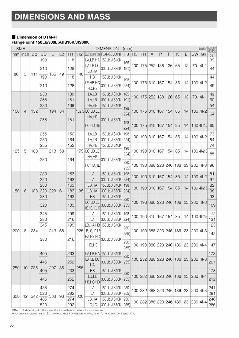
■ Dimension of DTM-4IFlange joint:150Lb/300Lb/JIS10K/JIS30K
35
DIMENSIONS AND MASS
mm
80
100
125
150
200
250
300
inch
3
4
5
6
8
10
12
φd
111
132
160
188
234
286
342
φD190
210
190
210
230255230
255
255280255
280
280320280320280
320
345380345
380
405
445
405
445
485520485520
L
165
194
213
229
243
297
338
H1118
128
118
128
139151139
151
152164152
164
163183163183163
183
199216199
216
233
252
233
252
274292274292
H2
140
162.5
175
195
225
255
300
L2
49
54
58
61
68
85
93
H3
165(191)
198(224)
165(191)
198(224)
198(224)198
(224)
198(224)
230(255)198
(224)198
(224)
230(255)
198(224)
230(255)
230(255)
230(255)
230(255)
230(255)230
(255)
H5
100
100
100
100
100
100
100
100
100
100
100
100
100
100
100
100
100
100
H4
175
175
175
175
175
190
190
190
190
190
190
190
190
190
232
232
232
232
A
252
310
252
310
310
310
310
388
310
310
388
310
388
388
388
388
388
388
P
138
167
138
167
167
167
167
223
167
167
223
167
223
223
223
223
223
223
F
126
154
126
154
154
154
154
246
154
154
246
154
246
246
246
246
246
246
K
65
85
65
85
85
85
85
136
85
85
136
85
136
136
136
136
136
136
E
12
14
12
14
14
14
14
23
14
14
23
14
23
23
23
23
23
23
φW
70
100
70
100
100
100
100
200
100
100
200
100
200
280
200
280
200
280
MOTOR
TYPE
4I-1
4I-2
4I-1
4I-2
4I-2.5
4I-2
4I-2.5
4I-3
4I-2
4I-2.5
4I-3
4I-2.5
4I-3
4I-4
4I-3
4I-4
4I-3
4I-4
39
44
44
49
496054
64
65
738474
85
96
8197829893
109
112131123
142
147
173
207
178
212
241281246286
SELECTION CRITERIALA,LB,HALA,LB,LC
LD,HAHB
LE,HB,HCHD,HELA,LBLA,LBHA,HB
LC,LD,LEHA,HB
HC,HD,HE
LA,LBLA,LBHA,HB
LC,LD,LEHA,HB
HC,HD,HE
LALA
LB,HALB,HA
HBLC,LD,LEHB,HC,HD,HE
LALA
LB,HA,HBLB,LC,LD,LEHA,HB,HC
HD,HE
LA,LB,HALA,LB,LC
HAHB
LD,LEHB,HC,HD
LALA
LB,HALC,LD
FLANGE JOINT150Lb,JIS10K
300Lb,JIS30K
150Lb,JIS10K
300Lb,JIS30K
150Lb,JIS10K300Lb,JIS30K150Lb,JIS10K
300Lb,JIS30K
150Lb,JIS10K300Lb,JIS30K150Lb,JIS10K
300Lb,JIS30K
150Lb,JIS10K300Lb,JIS30K150Lb,JIS10K300Lb,JIS30K150Lb,JIS10K
300Lb,JIS30K
150Lb,JIS10K300Lb,JIS30K150Lb,JIS10K
300Lb,JIS30K
150Lb,JIS10K
300Lb,JIS30K
150Lb,JIS10K
300Lb,JIS30K
150Lb,JIS10K300Lb,JIS30K150Lb,JIS10K300Lb,JIS30K
SIZE DIMENSION (mm)
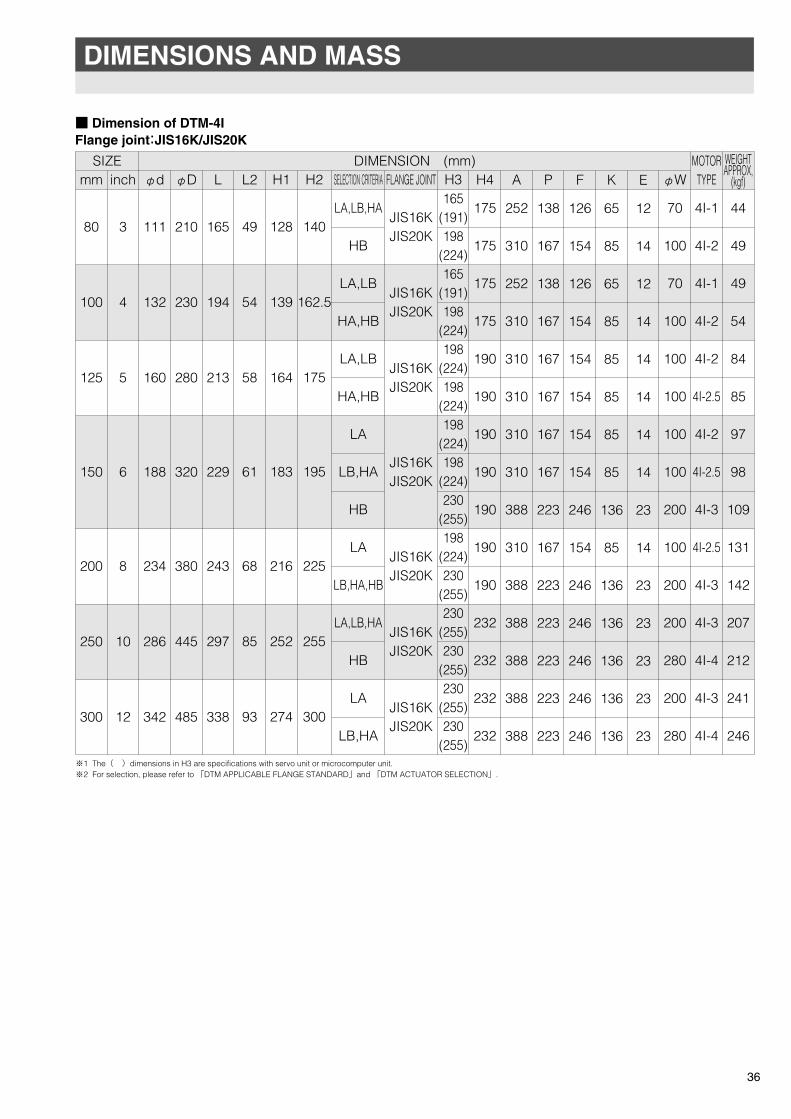
※The( )dimensions in H3 are specifications with servo unit or microcomputer unit.※ For selection, please refer to 「DTM APPLICABLE FLANGE STANDARD」and 「DTM ACTUATOR SELECTION」.
WEIGHTAPPROX,
(kgf)
TOMOE-eng 11.2.18 18:28 ページ 36
DIMENSIONS AND MASS
■ Dimension of DTM-4IFlange joint:JIS16K/JIS20K
36
mm
80
100
125
150
200
250
300
inch
3
4
5
6
8
10
12
φd
111
132
160
188
234
286
342
φD
210
230
280
320
380
445
485
L
165
194
213
229
243
297
338
L2
49
54
58
61
68
85
93
H1
128
139
164
183
216
252
274
H2
140
162.5
175
195
225
255
300
H3165
(191)198
(224)165
(191)198
(224)198
(224)198
(224)198
(224)198
(224)230
(255)198
(224)230
(255)230
(255)230
(255)230
(255)230
(255)
H4
175
175
175
175
190
190
190
190
190
190
190
232
232
232
232
A
252
310
252
310
310
310
310
310
388
310
388
388
388
388
388
P
138
167
138
167
167
167
167
167
223
167
223
223
223
223
223
F
126
154
126
154
154
154
154
154
246
154
246
246
246
246
246
K
65
85
65
85
85
85
85
85
136
85
136
136
136
136
136
E
12
14
12
14
14
14
14
14
23
14
23
23
23
23
23
φW
70
100
70
100
100
100
100
100
200
100
200
200
280
200
280
SELECTION CRITERIA
LA,LB,HA
HB
LA,LB
HA,HB
LA,LB
HA,HB
LA
LB,HA
HB
LA
LB,HA,HB
LA,LB,HA
HB
LA
LB,HA
FLANGE JOINT
JIS16KJIS20K
JIS16KJIS20K
JIS16KJIS20K
JIS16KJIS20K
JIS16KJIS20K
JIS16KJIS20K
JIS16KJIS20K
SIZE DIMENSION (mm)
※1 The( )dimensions in H3 are specifications with servo unit or microcomputer unit.※2 For selection, please refer to 「DTM APPLICABLE FLANGE STANDARD」and 「DTM ACTUATOR SELECTION」.
MOTORTYPE
4I-1
4I-2
4I-1
4I-2
4I-2
4I-2.5
4I-2
4I-2.5
4I-3
4I-2.5
4I-3
4I-3
4I-4
4I-3
4I-4
44
49
49
54
84
85
97
98
109
131
142
207
212
241
246
WEIGHTAPPROX,
(kgf)
TOMOE-eng 11.2.18 18:28 ページ 37
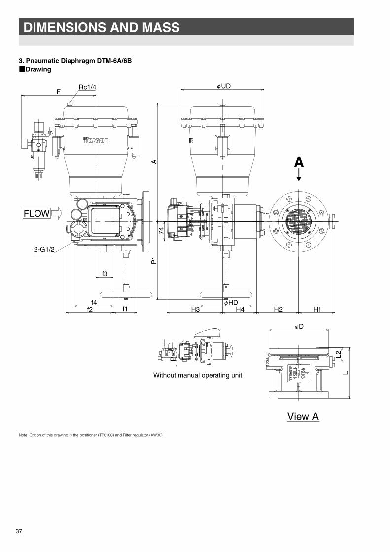
3. Pneumatic Diaphragm DTM-6A/6B■Drawing
37
DIMENSIONS AND MASS
Note: Option of this drawing is the positioner (TP8100) and Filter regulator (AW30).
f2
F
f3
f1f4
Rc1/4
2-G1/2
FLOW
H3
74
H1H2H4
P1
A
UD
HD
A↓�
L
D
L2
View A
P
Without manual operating unit
φ�
φ�
φ�
TOMOE-eng 10.10.12 17:58 ページ 38
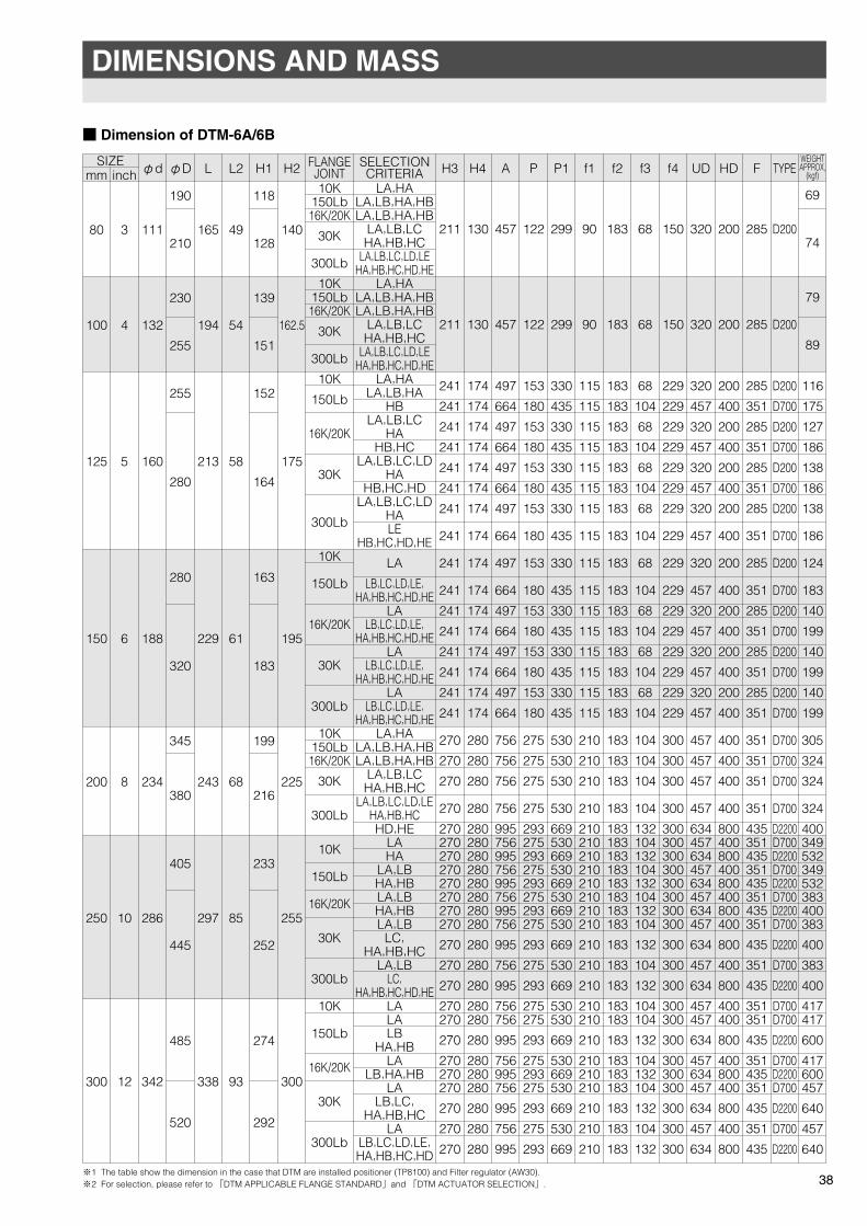
■ Dimension of DTM-6A/6B
38
mm
80
100
125
150
200
250
300
inch
3
4
5
6
8
10
12
φd
111
132
160
188
234
286
342
φD
190
210
230
255
255
280
280
320
345
380
405
445
485
520
L
165
194
213
229
243
297
338
L2
49
54
58
61
68
85
93
H1
118
128
139
151
152
164
163
183
199
216
233
252
274
292
H2
140
162.5
175
195
225
255
300
FLANGEJOINT10K
150Lb16K/20K
30K
300Lb
10K150Lb16K/20K
30K
300Lb
10K
150Lb
16K/20K
30K
300Lb
10K
150Lb
16K/20K
30K
300Lb
10K150Lb16K/20K
30K
300Lb
10K
150Lb
16K/20K
30K
300Lb
10K
150Lb
16K/20K
30K
300Lb
SELECTIONCRITERIA
LA,HALA,LB,HA,HBLA,LB,HA,HB
LA,LB,LCHA,HB,HC
LA,LB,LC,LD,LEHA,HB,HC,HD,HE
LA,HALA,LB,HA,HBLA,LB,HA,HB
LA,LB,LCHA,HB,HC
LA,LB,LC,LD,LEHA,HB,HC,HD,HE
LA,HALA,LB,HA
HBLA,LB,LC
HAHB,HC
LA,LB,LC,LDHA
HB,HC,HDLA,LB,LC,LD
HALE
HB,HC,HD,HE
LA
LB,LC,LD,LE,HA,HB,HC,HD,HE
LALB,LC,LD,LE,
HA,HB,HC,HD,HELA
LB,LC,LD,LE,HA,HB,HC,HD,HE
LALB,LC,LD,LE,
HA,HB,HC,HD,HELA,HA
LA,LB,HA,HBLA,LB,HA,HB
LA,LB,LCHA,HB,HC
LA,LB,LC,LD,LEHA,HB,HCHD,HE
LAHA
LA,LBHA,HBLA,LBHA,HBLA,LB
LC,HA,HB,HC
LA,LBLC,
HA,HB,HC,HD,HELALALB
HA,HBLA
LB,HA,HBLA
LB,LC,HA,HB,HC
LALB,LC,LD,LE,HA,HB,HC,HD
H3
211
211
241
241
241
241
241
241
241
241
241
241
241
241
241
241
241
241
270
270
270
270
270270270270270270270270
270
270
270
270270
270
270270270
270
270
270
H4
130
130
174
174
174
174
174
174
174
174
174
174
174
174
174
174
174
174
280
280
280
280
280280280280280280280280
280
280
280
280280
280
280280280
280
280
280
A
457
457
497
664
497
664
497
664
497
664
497
664
497
664
497
664
497
664
756
756
756
756
995756995756995756995756
995
756
995
756756
995
756995756
995
756
995
P
122
122
153
180
153
180
153
180
153
180
153
180
153
180
153
180
153
180
275
275
275
275
293275293275293275293275
293
275
293
275275
293
275293275
293
275
293
P1
299
299
330
435
330
435
330
435
330
435
330
435
330
435
330
435
330
435
530
530
530
530
669530669530669530669530
669
530
669
530530
669
530669530
669
530
669
f1
90
90
115
115
115
115
115
115
115
115
115
115
115
115
115
115
115
115
210
210
210
210
210210210210210210210210
210
210
210
210210
210
210210210
210
210
210
f2
183
183
183
183
183
183
183
183
183
183
183
183
183
183
183
183
183
183
183
183
183
183
183183183183183183183183
183
183
183
183183
183
183183183
183
183
183
f3
68
68
68
104
68
104
68
104
68
104
68
104
68
104
68
104
68
104
104
104
104
104
132104132104132104132104
132
104
132
104104
132
104132104
132
104
132
f4
150
150
229
229
229
229
229
229
229
229
229
229
229
229
229
229
229
229
300
300
300
300
300300300300300300300300
300
300
300
300300
300
300300300
300
300
300
UD
320
320
320
457
320
457
320
457
320
457
320
457
320
457
320
457
320
457
457
457
457
457
634457634457634457634457
634
457
634
457457
634
457634457
634
457
634
HD
200
200
200
400
200
400
200
400
200
400
200
400
200
400
200
400
200
400
400
400
400
400
800400800400800400800400
800
400
800
400400
800
400800400
800
400
800
F
285
285
285
351
285
351
285
351
285
351
285
351
285
351
285
351
285
351
351
351
351
351
435351435351435351435351
435
351
435
351351
435
351435351
435
351
435
TYPE
D200
D200
D200
D700
D200
D700
D200
D700
D200
D700
D200
D700
D200
D700
D200
D700
D200
D700
D700
D700
D700
D700
D2200D700D2200D700D2200D700D2200D700
D2200
D700
D2200
D700D700
D2200
D700D2200D700
D2200
D700
D2200
WEIGHTAPPROX,
(kgf)
69
74
79
89
116
175
127
186
138
186
138
186
124
183
140
199
140
199
140
199
305
324
324
324
400349532349532383400383
400
383
400
417417
600
417600457
640
457
640
SIZE
※1 The table show the dimension in the case that DTM are installed positioner (TP8100) and Filter regulator (AW30).※2 For selection, please refer to 「DTM APPLICABLE FLANGE STANDARD」and 「DTM ACTUATOR SELECTION」.
DIMENSIONS AND MASS
TOMOE-eng 11.2.18 18:28 ページ 39
This instruction manual explains standard usage of
the Ultimate Rotary Control Valve DTM.
Please read this manual thoroughly in order to ensure correct use of the product.
www.tomoeeurope.co.uk
●Head Office������� �������� �������� ��� ��������� ������������� ������������������������� ���� !� �������������������� "��������#$���%�%�&��
'��()$�( *�+� ,�����)- .�+�)� /�+��$(�� "�$$�� �)��($� ���$� 0��� 1�2 3��� 4��$�+ 5��6+����������� �33������������ ���� !� �33������������ "��������#$���%�%�&��&�� ����#$���$(�$��&��&��
���� *����+ 7(�%� ���$� ����5��6)��+� 8���$�� ��!�� 99��2� 4�:���������� �����������9�9��9��2 ���� !� �����������9���
;�� � '�� 1��6 *�+ <�9��� ���6��(� ��229����������� ������22���� ���� !� ������22���� "��������#$���&��&�6
Global Sales Operations
�&�9�� ;� :� *�+�.�� ��)����+��6 7��$(��$ ���6���������&'8/ :&���������� ��������2�����9 ���� !� ��������2������
www.tomoe.com.sg/index.php
'$& �&".�����① ����&�&2��=�